
Methods to directly measure non- resonant stellar reaction rates Tanja Geib.
Upload
aditya-agarwalCategory
view
502download
3description

What is difference between resonant and non-resonant antenna?Answer:
Every antenna is at resonance according to length to which it is cut ! They are usually cut
to resonate at a particular band of frequencies, ie, Vhf Television band etc.
If no resonance then no signal is present and in such a case antenna is merely a random
chunk of metal.
The magnetic field that an antenna puts out will produce an electric current on any conducting
surface that it strikes, however if that surface has a characteristic length the induced current will
be much stronger on the object. For example, when a Citizens Band signal travels through the
air, it completes a cycle in approximately 36 feet. If the object that the magnetic wave strikes is
18 feet long (1/2 wave length), 9 feet long (1/4 wavelength) or 36 feet long (1 full wavelength),
then the induced current will be much higher than if the signal struck a metal object that was not
some appreciable fraction of the wavelength of the signal.
A resonant antenna is so much more efficient at converting (receiving or transmitting) current
between the field and the antenna's feed-point than a non-resonant antenna that much effort is
put into configuring resonance. A non-resonant antenna still works as an antenna but simply
requires a more sensitive receiver or more powerful transmitter.
If you have ever heard people say they want to "tune" their antenna, they usually mean they
mechanically change lengths in relation to the frequency / wavelength they are trying to match. It
is also possible to change electrical properties to match frequency, which is more handy for
matching multiple frequencies with a single antenna.
nverted vee antennaFrom Wikipedia, the free encyclopedia
This article does not cite any references or sources. Please help improve this article by adding citations to reliable sources. Unsourced material may be challenged and removed. (March 2008)

An inverted vee antenna is a type of antenna in which the two side of the dipole are perpendicular to each
other instead of parallel. It is typically used in areas of limited space as it can significantly reduce the
ground foot print of the antenna without significantly impacting performance. Viewed from the side, it looks
like the English letter "V" turned upside down, hence the name. Inverted vee antennas are commonly used
by amateur radio stations, and aboard sailing vessels requiring better HF performance than available with a
short whip antenna. Inverted vee antennas are horizontally polarizedand they are almost omnidirectional as
compared to a traditional dipole in which they have a deep null off the ends.
Typical amateur radio inverted vee installed on roof. This multiband antenna allows transmissions on the 40/20/15/10
meter bands. Center point is held up with masting and ends are secured to roof. Two VHF verticals are also shown.
[edit]Use
Typically, the inverted vee antenna requires only a single, tall support at the center, and the ends can be
insulated and secured to anchors near ground level or near the roof if mounted on a house. This simplified
arrangement has several advantages, including a shorter ground distance between the ends. For example,
a dipole antenna for the 80 meter band requires a ground length of about 140 feet (43 m) from end to end.
An inverted vee with a 40-foot (12 m) apex elevation requires only 115 feet (35 m). For radio
amateurs living on small parcels of property, such savings can make it possible to use the lower frequency
amateur bands.
[edit]Properties
In theory, the gain of an inverted vee is similar to that of a dipole at the same elevation because most of the
radiation is from the high-current portion of the antenna, which is near the center. Since the center of both
antennas are the same height, there is little difference in performance. Antenna modeling software bears
this out for free-space models, predicting maximum gain of 2.15 dBi for the dipole and 1.9 dBi for the
inverted vee.
However, in practice, ground proximity and ground conductivity as well as end effects reduce the efficiency
of the inverted vee considerably compared to the dipole: In the 40-foot example above, considering a

useful take-off angle of 40 degrees above the horizon, the inverted vee produces a maximum gain of 1 dBi
in a circular pattern, whereas the dipole produces an oval pattern ranging from 6 dBi toward the sides down
to 1.2 dBi toward the ends.
Elevating the antennas higher above ground somewhat resolves the disparity, but considering the practical,
legal and financial limits which influence most antenna installations, the inverted vee will be observably
inferior in performance to a dipole by 1 to 2 S-units. However, if space is limited, an inverted vee may
permit operation on frequencies that would not be possible with a full-sized dipole.
[hide]
V
T
E
Antenna types
Isotropic Isotropic radiator
Omnidirectional Biconical antenna
Cage aerial
Choke ring antenna
Coaxial antenna
Crossed field antenna
Dielectric Resonator Antenna
Discone antenna
Folded unipole antenna

Franklin antenna
Ground-plane antenna
Halo antenna
Helical antenna
J-pole antenna
Mast radiator
Monopole antenna
Random wire antenna
Rubber Ducky antenna
T2FD Antenna
T-aerial
Umbrella antenna
Whip antenna
Directional Adcock antenna
AWX antenna
Beverage antenna
Cantenna

Cassegrain antenna
Collinear antenna
Conformal antenna
Dipole antenna
Folded Inverted Conformal Antenna
Fractal antenna
Gizmotchy
Helical antenna
Horizontal curtain
Horn antenna
HRS antenna
Inverted vee antenna
Log-periodic antenna
Loop antenna
Microstrip antenna
Offset dish antenna

Patch antenna
Phased array
Parabolic antenna
Plasma antenna
Quad antenna
Reflective array antenna
Regenerative loop antenna
Rhombic antenna
Sector antenna
Short backfire antenna
Slot antenna
Turnstile antenna
Vivaldi-antenna
WokFi
Yagi-Uda antenna
Application-specific ALLISS
Ground dipole

Evolved antenna
Rectenna
Reference antenna
Wullenweber
Rhombic Antennas, V-beam, and Inverted V
(also see related page curtain arrays)
The rhombic antenna is often claimed to be an exceptionally good antenna with very high gain. We will look at a few rhombic antenna designs (including an Inverted V) in the article below.
If we look at this link to this pdf document on rhombic design we find suggested dimensions for rhombic antennas. That page agrees with other data I can find on rhombics, such as the once very popular Radio Handbook by Bill Orr W6SAI.
My modeled data agrees with other independent rhombic antenna
models. For example, if we look at the data on the PA6Z Rhombic antenna page we will find the following rhombic gain values for a 320-meter total wire length rhombic:
14 MHz = 15.95 dBi
7 MHz = 10.79 dBi
While this might initially seem like a great deal of gain, we have to remember it includes ground reflection gain. A dipole at reasonable heights typically has over 8 dBi gain. Translating the dBi gain values above to a more standard dBd we have the following:
14 MHz = 15.95 dBi or 7.5 to 8 dBd gain for the 320-meter wire length rhombic
7 MHz = 10.79 dBi or 2.3 to 2.8 dBd gain for the 320-meter wire length rhombic
The argument rhombics are "very high gain antennas" seems to fall apart when we compare rhombic antennas to a standard dipole reference antenna with both antennas at the same height. Rhombics do have advantages, but it seems there is a widespread tendency to exaggerate or misunderstand gain. The purpose of this page is to factually describe and illustrate the advantages and disadvantages of rhombic antennas.
Model of a Rhombic Antenna
Let's look at a 2 WL per leg 40-meter rhombic design 120 feet high over medium conductivity soil using number 8 AWG bare copper wire with an 800 ohm termination.
V angle at each end: 70 degrees
Side length (one of four sides): 252 feet
Overall width: 290 feet
Overall length: 414 feet

At first glance our response might be this is a lot of gain. After all, the gain is a whopping 14.42 dBi for this 414 foot long 290 foot wide rhombic antenna. But to get a good idea of the real gain, we should compare it to a dipole or some other standard antenna at the same height. When we do that, we find this large 40 meter rhombic antenna has about (14.42 dBi - 8.5 dBi) 6 dBd gain. The efficiency is a fairly low 46.6%
Let's double the size and readjust side angles for optimum gain at the new leg length and see what happens......
We now find the following design specifications for an even larger 4 wavelength-per-leg 40 meter rhombic:
V angle at each end: 47 degrees
Side length: 504.4 feet
Overall width: 687.9 feet
Overall length: 737.9 feet
This antenna would use over 2000 feet of wire, and here is how this monster antenna performs at a height of 200 feet above ground.
From EZnec+ ver. 5.0 we have the following patterns:

The overall efficiency is 47.2%
This rhombic has 16.64-8.5 = 8.14 dBd gain. This is actually about the gain of a pair of 3-element Yagi antennas stacked. Let's compare the

Rhombic to a pair of three element Yagi antenna for 40 meters. Here is the pattern and gain of my two-antenna high 40 meter stack of three element Yagi antennas:

The gain of this antenna system is 7.73 dBd. My two three-element 40 meter antennas are within 1/2 dB of a rhombic 200 feet high occupying a 700 ft by 750 ft area. More important when we look at patterns, the 40 meter Yagi antennas have a cleaner broader pattern. This means less fading and better coverage in the target area using the much smaller Yagi antenna system!
Let's try comparing the rhombic to my planned distributed feed curtain array:
My planned curtain, at 285 feet high and 340 feet wide, has 21.9 dBi gain. Referencing a dipole over earth this is 21.9 - 8.5 = 13.4 dBd gain.
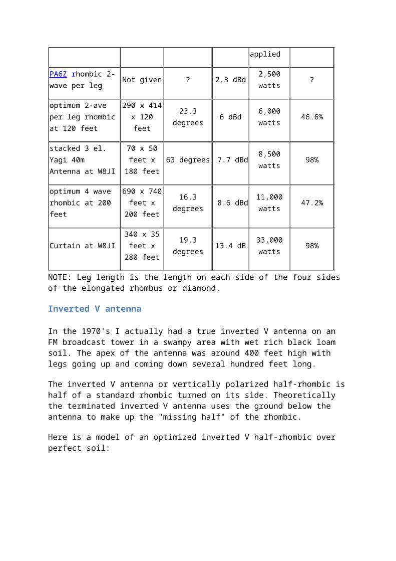
40-meter Rhombic Performance

Comparison
AntennaPhysical size W x L x H
-3dB Beamwidth
Typical gain over dipole
Typical ERP with 1500 watts applied
Antenna
Efficiency
PA6Z rhombic 2-wave per leg
Not given ? 2.3 dBd2,500 watts
?
optimum 2-ave per leg rhombic at 120 feet
290 x 414 x 120 feet
23.3 degrees
6 dBd6,000 watts
46.6%
stacked 3 el. Yagi 40m Antenna at W8JI
70 x 50 feet x 180
feet63 degrees 7.7 dBd
8,500 watts
98%
optimum 4 wave rhombic at 200 feet
690 x 740 feet x 200
feet
16.3 degrees
8.6 dBd11,000 watts
47.2%
Curtain at W8JI340 x 35
feet x 280 feet
19.3 degrees
13.4 dB33,000 watts
98%
NOTE: Leg length is the length on each side of the four sides of the elongated rhombus or diamond.
Inverted V antenna
In the 1970's I actually had a true inverted V antenna on an FM broadcast tower in a swampy area with wet rich black loam soil. The apex of the antenna was around 400 feet high with legs going up and coming down several hundred feet long.
The inverted V antenna or vertically polarized half-rhombic is half of a standard rhombic turned on its side. Theoretically the terminated inverted V antenna uses the ground below the antenna to make up the "missing half" of the rhombic.
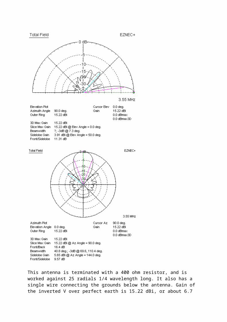
Here is a model of an optimized inverted V half-rhombic over perfect soil:

This antenna is terminated with a 400 ohm resistor, and is worked against 25 radials 1/4 wavelength long. It also has a single wire connecting the grounds below the antenna. Gain of the inverted V over perfect earth is
15.22 dBi, or about 6.7 dB over a dipole at optimum height.
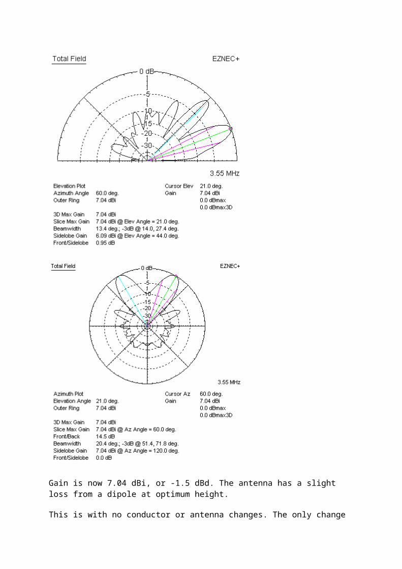
Changing the above antenna's earth to good soil (15 ms/m) with no other changes we have the following patterns:
Gain is now 7.04 dBi, or -1.5 dBd. The antenna has a slight loss from a dipole at optimum height.
This is with no conductor or antenna changes. The only change is the soil

type, which went from perfect lossless soil to good soil.
This actually agrees with my tests at the broadcast station. While I could get reasonable F/B ratio, I had loss over a dipole in the direction the antenna was pointed. After one season I removed my large inverted V antennas and went with a regular dipole antenna about 330 feet in the air.
V-Beam Antenna
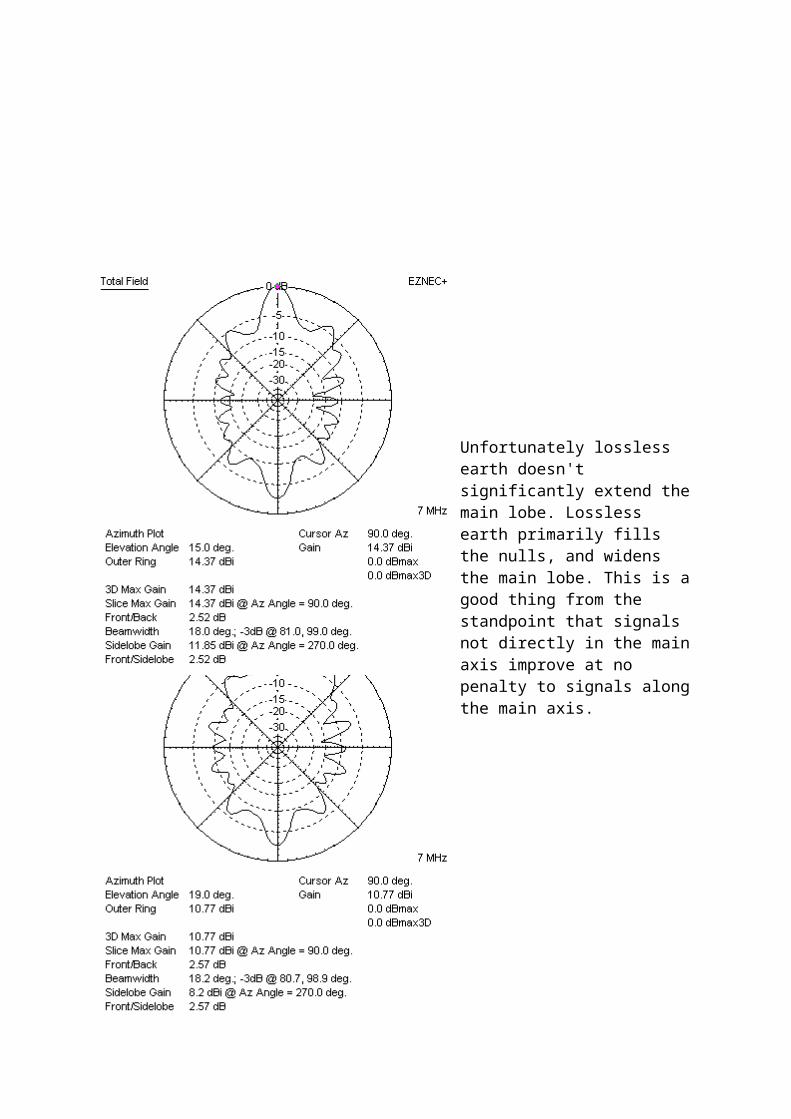
The V-beam antenna is the first part of a rhombic antenna. It omits the closing end of the rhombic. As such, we can model it by removing the outer half of a rhombic. This is a four wavelength-per-leg 40-meter V-beam antenna:
Gain is 14.15 dBi, or about 6 dB over a dipole. This gain is approximately equal to a small three element Yagi antenna. The main problems is, like the rhombic, the half-power beamwidth is very narrow for the gain. A low gain-beamwidth product occurs because antenna efficiency, even for unterminated systems, is only around 70%.
Much of the 30% power loss is in earth below the antenna. Efficiency climbs to 92% when this antenna is over perfect earth. In the case of perfect earth, the
remaining 8% loss is due to copper losses in the very long #8 copper antenna conductors.
Unfortunately lossless earth doesn't significantly extend the main lobe. Lossless earth primarily fills the nulls, and widens the main lobe. This is a good thing from the standpoint that signals not directly in the main axis improve at no penalty to signals along the main axis.
Long wire arrays are also height sensitive. Reduced height greatly lowers efficiency, and a good goal for minimum height is 1/4 of the antenna's leg length. The 4-wavelength per leg V-beam had 6 dBd gain when just under 1 wavelength high.
Reducing height to just under 1/2 wave reduces gain to about 3 dBd or less. The antenna gave up almost 4 dB

of antenna gain for a 60-foot height change on a 40-meter antenna, moving it into the gain range of a simple small extended double Zepp wire antenna. The extended double Zepp would have a wider main lobe for the same gain, because it has higher efficiency. It would also have deeper nulls in the null area.
Conclusion
Rhombic and related V antennas are often described as extremely high gain antennas, but that claim seems to be a little exaggerated or inflated. A 2-wavelength per leg rhombic actually has about the same gain as a single three-element monoband Yagi antenna on the design band. Most of the rhombic's performance limitations come from the high levels of spurious lobes and the very poor efficiency, especially over normal soil. The rhombic has one of the poorest gain-per-acre rankings of any high gain HF antenna array. On the other hand a rhombic antenna does have the very distinct advantage of working over very wide frequency ranges with good SWR and gain, something a basic monoband Yagi can never do. The rhombic is also a simple antenna, requiring only four supports (three supports for the V beam, and one support for inverted V derivatives).
In a large properly designed rhombic, slightly less than half of applied RF power is lost in the termination system. That power is converted to heat. Right away this puts the rhombic at a ~3 dB disadvantage to other more efficient antennas with a similar overall pattern shape or half-power beamwidth. There are ways to use this power but generally very little appears in rhombic resources.
Efficiency and gain could be improved if we recirculated termination power. Rather than converting the power to heat, we could recombine the termination RF back into the main feeder system. Such recombining or recirculating schemes would be fairly simple, although they would require readjustment if the operating frequency was changed. A recirculating system would be comprised of an impedance matching network or stub and phasing system to bring the termination signal back in phase with the applied power. By recombining power that would otherwise be wasted as heat back into the feed system, system gain would increase 2 to 3 dB. ( I actually used such a system with an "inverted V antenna", which is
actually a vertically polarized half-rhombic antenna. )
Even though not quite the extremely high gain system we are led to believe, the rhombic is not without major advantages over other antennas. It is easy to construct and somewhat non-critical of dimensions. It offers very wide bandwidth performance, being competitive with large log periodic arrays. If we need an easy-to-install very broadband antenna that can easily handle high power and if we are not particularly worried about gain or efficiency, a rhombic is a worthwhile antenna to consider. The many spurious lobes, while they do rob significant power from the main lobe, can also fill in other directions while transmitting. This is sometimes a plus for broadcasting, if we can align the side lobes with populated areas. Rhombics are not the extremely high gain antennas we are sometimes led to believe, but they do have very distinct advantages when it comes to bandwidth, power handling, ease of construction, and physical and electrical simplicity. The rhombic is a moderate gain very wide bandwidth antenna capable of handling very high power.
Since 11/11/2008
Ferrite rod antenna- an overview, summary, tutorial about the ferrite rod antenna or aerial, a form of RF antenna that is widely used in RFID and transistor radio applications.
Ferrite rod antenna information includes: • Ferrite rod antenna basics • Ferrite rod antenna parameters
The ferrite rod antenna is a form of RF antenna design that is almost universally used in portable
transistor broadcast receivers as well as many hi-fi tuners where reception on the long, medium
and possibly the short wave bands is required.
Ferrite rod antennas are also being used increasingly in wireless applications in areas such as RFID.
Here the volumes of antennas required can be huge. The antennas also need to be compact and
effective, making ferrite rod antennas an ideal solution.
Ferrite rod antenna basicsAs the name suggests the antenna consists of a rod made of ferrite, an iron based magnetic
material. A coil is would around the ferrite rod and this is brought to resonance using a variable
tuning capacitor contained within the radio circuitry itself and in this way the antenna can be tuned
to resonance. As the antenna is tuned it usually forms the RF tuning circuit for the receiver,
enabling both functions to be combined within the same components, thereby reducing the
number of components and hence the cost of the set.

Typical ferrite rod antenna assembly used in a portable radio
The ferrite rod antenna operates using the high permeability of the ferrite material and in its basic
form this may be thought of as "concentrating" the magnetic component of the radio waves. This is
brought about by the high permeability μ of the ferrite.
The fact that this RF antenna uses the magnetic component of the radio signals in this way means
that the antenna is directive. It operates best only when the magnetic lines of force fall in line with
the antenna. This occurs when it is at right angles to the direction of the transmitter. This means
that the antenna has a null position where the signal level is at a minimum when the antenna is in
line with the direction of the transmitter.
Operation of a ferrite rod antenna
Ferrite rod antenna performanceThis form of RF antenna design is very convenient for portable applications, but its efficiency is
much less than that of a larger RF antenna. The performance of the ferrite also limits the frequency
response. Normally this type of RF antenna design is only effective on the long and medium wave
bands, but it is sometimes used for lower frequencies in the short wave bands although the
performance is significantly degraded, mainly arising from the losses in the ferrite. This limits their
operation normally to frequencies up to 2 or 3 MHz.
Ferrite rod antennas are normally only used for receiving. They are rarely used for transmitting
anything above low levels of power in view of their poor efficiency. It any reasonable levels of
power were fed into them they would soon become very hot and there would be a high likelihood
that they would be destroyed. Nevertheless they can be used as a very compact form of
transmitting antenna for applications where efficiency is not an issue and where power levels are
very low. As they are very much more compact than other forms of low or medium frequency RF
antenna, this can be an advantage, and as a result they are being used in applications such as
RFID.
Ferrite Rod Antenna Parameters
- notes and overview about some of the key parameters associated with ferrite rod antennas and their performance.
Ferrite rod antenna information includes: • Ferrite rod antenna basics • Ferrite rod antenna parameters
There are a number of ferrite rod parameters that are of key interest when considering their use in
any application.
The two main parameters are the Q of the tuned circuit, and the radiation resistance. These two
ferrite rod parameters govern the areas in which they can be used. The size of the ferrite rod
antenna means that there are some compromises that need to be made in other areas of their
performance. Accordingly it is necessary to make the right balance between the important
requirements.
Ferrite rod antenna QOne of the requirements for an efficient ferrite rod antenna is that it should have a high Q at the
frequencies over which it operates. At frequencies of a few hundred kilohertz, a medium
permeability material would be used and this would enable a Q of about 1000 to be obtained. With
a Q of this value it will mean that the antenna will need tuning if it is to operate over more than a
single channel or frequency. When used in a portable receiver, the tuning can be linked to the
overall receiver tuning and indeed the ferrite rod antenna normally provides the input tuning for
the set.
Typical ferrite rod antenna assembly used in a portable radio
The Qs of the overall antenna may appear very high, and in fact the ferrite in a rod form has a
much higher Q than the basic material as a result of the fact that the rod forms an open magnetic
circuit.
Radiation resistance of a ferrite rod antennaOne of the advantages of using a ferrite in the antenna is that it brings the radiation resistance of
the overall antenna to a more reasonable level. The ferrite rod antenna can be considered as a
small loop antenna. In view of its size, the loop is much less than a wavelength in length and
without the ferrite it would have a very low radiation resistance. Accordingly the losses due to the

resistance of the wire would be exceedingly high. Placing the ferrite core in the coil has the effect
of raising the radiation resistance by a factor of μ^2, and thereby bring the value into more
acceptable limits.
While the introduction of the ferrite rod raises the radiation resistance of the antenna, and hence
reduce the losses due to the resistance of the wire, it does introduce other losses. The ferrite itself
absorbs power. This arises from the energy required to change the magnetic alignment of the
magnetic domains inside the granular structure of the ferrite. The higher the frequency, the
greater the number of changes and hence the higher the loss.
SummaryThe ferrite rod antenna is a particularly useful form of RF antenna design despite its limitations and
drawbacks in terms of efficiency, top frequency and the need for tuning. Nevertheless ferrite rod
antennas are widely used, being used almost universally as the RF antenna in portable radios for
long and medium waveband reception as well as being used in a number of RFID applications.


