What is a seismic reflector like?
12
HAL Id: hal-00461558 https://hal.archives-ouvertes.fr/hal-00461558 Submitted on 21 Jan 2014 HAL is a multi-disciplinary open access archive for the deposit and dissemination of sci- entific research documents, whether they are pub- lished or not. The documents may come from teaching and research institutions in France or abroad, or from public or private research centers. L’archive ouverte pluridisciplinaire HAL, est destinée au dépôt et à la diffusion de documents scientifiques de niveau recherche, publiés ou non, émanant des établissements d’enseignement et de recherche français ou étrangers, des laboratoires publics ou privés. What is a seismic reflector like? Nathalie Favretto-Cristini, Paul Cristini, Eric de Bazelaire To cite this version: Nathalie Favretto-Cristini, Paul Cristini, Eric de Bazelaire. What is a seismic reflector like?. Geo- physics, Society of Exploration Geophysicists, 2009, 74 (1), pp.T13-T23. 10.1190/1.3033216. hal- 00461558
Transcript of What is a seismic reflector like?

HAL Id: hal-00461558https://hal.archives-ouvertes.fr/hal-00461558
Submitted on 21 Jan 2014
HAL is a multi-disciplinary open accessarchive for the deposit and dissemination of sci-entific research documents, whether they are pub-lished or not. The documents may come fromteaching and research institutions in France orabroad, or from public or private research centers.
L’archive ouverte pluridisciplinaire HAL, estdestinée au dépôt et à la diffusion de documentsscientifiques de niveau recherche, publiés ou non,émanant des établissements d’enseignement et derecherche français ou étrangers, des laboratoirespublics ou privés.
What is a seismic reflector like?Nathalie Favretto-Cristini, Paul Cristini, Eric de Bazelaire
To cite this version:Nathalie Favretto-Cristini, Paul Cristini, Eric de Bazelaire. What is a seismic reflector like?. Geo-physics, Society of Exploration Geophysicists, 2009, 74 (1), pp.T13-T23. �10.1190/1.3033216�. �hal-00461558�
W
N
Ncao
c
©
GEOPHYSICS, VOL. 74, NO. 1 �JANUARY-FEBRUARY 2009�; P. T13–T23, 11 FIGS.10.1190/1.3033216
hat is a seismic reflector like?
athalie Favretto-Cristini1, Paul Cristini1, and Eric de Bazelaire2
aewcvsvm2c
ccurztroa
lppwi
odrnfrmiCa
ved 21 Jéoscienrance.
ABSTRACT
The spatial region that is in the vicinity of an interface andactually affects the interface response, and hence the reflect-ed wavefield, is of particular interest for the characterizationof reflectors from a seismic viewpoint. This region is repre-sented by a volume of integration of medium propertiesabove and below the interface whose maximum lateral extentcorresponds to the lateral extent of the interface Fresnel zone,and whose maximum vertical extent is equal to a thicknesswe evaluate approximately for subcritical incidence anglesfor a plane interface as well as for curved interfaces of anti-cline and syncline type. The maximum vertical extent mightbe larger than the seismic wavelengths for subcritical inci-dence angles close to the critical angle and for a strongimpedance contrast at the interface. Although the part of thereflector volume lying below the interface and affecting trav-eltime measurements actually is smaller than described inprevious studies, the whole part of the reflector volume thataffects the amplitude of the reflected wavefield is larger thanestimates in previous studies, which considered only the spa-tial region below the interface. For a syncline �respectively,an anticline�, it is larger �respectively, smaller� than de-scribed for a plane interface. In addition to providing morephysical insights into the wave reflection process, this studymight have significant implications for seismic interpretationusing amplitude-variation-with-angle methodologies.
INTRODUCTION
The basis of many seismic studies is ray theory �Červený, 2001�.evertheless, as measured seismic data have a finite low-frequency
ontent, it is accepted that seismic wave propagation is not limited ton infinitely narrow line called ray but is extended to a finite volumef space around the raypath �i.e., the first Fresnel volume� �Kravtsov
Manuscript received by the Editor 5 March 2008; revised manuscript recei1Formerly Université de Pau, Laboratoire de Modélisation et Imagerie en G
herche Scientifique, Laboratoire de Mécanique et d’Acoustique, Marseille, F2Deceased June 28, 20072009 Society of Exploration Geophysicists.All rights reserved.
T13
nd Orlov, 1990�, which contributes to the received wavefield forach frequency. The first Fresnel volume �FV� and its intersectionith an interface, called the interface Fresnel zone �IFZ�, have re-
eived wide attention in past decades. These concepts are being de-eloped continually, and they have found so many applications ineismology and seismic exploration that it is impossible here to re-iew all the books and articles that consider them in relation to seis-ic wave propagation �Schleicher et al., 1997; Spetzler and Snieder,
004; Zhou et al., 2005�. Nevertheless, we will mention the worksompiled in Červený �2001�.
Červený and his coauthors have suggested two methods that in-lude FV parameter calculations into the ray-tracing procedure inomplex 2D and 3D structures. The first method, called Fresnel vol-me ray tracing �Červený and Soares, 1992�, combines the paraxialay approximation with dynamic ray tracing and is applicable only toero-order waves �direct, reflected, and transmitted waves�, whereashe second method, more accurate than the first, is based on networkay tracing �Kvasnička and Červený, 1994�. Unfortunately, the sec-nd method can be applied only to waves arriving at receivers in firstrrivals.
Kvasnička and Červený �1994, 1996a, 1996b� have derived ana-ytic expressions for FVs of seismic body waves and for IFZ for sim-le structures with plane interfaces, offering deeper insight into theroperties of FV and IFZ. It is interesting to note that FV boundariesith corresponding FZ also can be estimated by using the method of
sochron rays �Iversen, 2004�.Of particular interest are the size of the IFZ and size of the volume
f the reflector involved in reflection time measurements �Hage-oorn, 1954� because each can be related to horizontal and verticalesolutions of seismic methods �Sheriff, 1980; Lindsey, 1989�. Untilow, only the IFZ and penetration depth of the FV below the inter-ace have been considered thus in studies. If seismic amplitudes ateceivers must be evaluated, the interface reflectivity must be deter-ined. It is well known that except for mathematical convenience,
nterfaces are not infinitely thin. The underlying question then is:onsidering an isolated interface, how thick are the spatial regions,bove and below the interface, that actually might affect the inter-
uly 2008; published online 29 December 2008.ces de Pau �MIGP�, CNRS, Pau, France; presently Centre National de la Re-
E-mail: [email protected]; [email protected]
fcp
kbTtwČČafvitI
odka�rse1aicaw
t�rnosrfafta
odttisuKctsie
wg
oodts�iaTut
flacslnfittutolc
ttVs
M
wfMo�dbcw
gb�ewt
fisrp
T14 Favretto-Cristini et al.
ace response and hence the reflected wavefield measured at the re-eivers? In other words, what is a reflector like from a seismic view-oint? That question is the focus of this paper.
As noted above, as most seismic wave propagation studies haveinematic objectives, only the IFZ and penetration depth of the FVelow the interface have received special attention in recent years.hey have been evaluated approximately by analytic expressions for
he case of a plane homogeneous interface �i.e., a plane interfaceith no lateral change in its physical properties� �Kvasnička andervený, 1996a� or by using network ray tracing �Kvasnička andervený, 1994�. Unfortunately, to our knowledge, the spatial regionbove the plane interface in the incidence medium, which also af-ects the interface response, has never been identified. In addition,ery few works are devoted to computations of the IFZ at a curvednterface. Moreover, most of these works are mainly concerned withhe case of normal wave incidence onto the interface �Lindsey, 1989;versen, 2006�.
We mention that Hubral and his coworkers found the projected FZf a zero-offset reflection onto the subsurface reflector using a stan-ard 3D common-midpoint �CMP� traveltime analysis, withoutnowing the reflector overburden �Hubral et al., 1993; Schleicher etl., 1997�. We refer also to the work of Kvasnička and Červený1994�. Using network ray tracing, they performed FV and IFZ pa-ameter calculations for the wave transmission process in simple 2Dtructures, such as a low-velocity body with a slightly curved shapembedded in a higher-velocity medium �Kvasnička and Červený,994�. Contrary to the work of Hubral and his coworkers �Hubral etl., 1993; Schleicher et al. 1997�, knowledge of the velocity models required for computations. Kvasnička and Červený �1994� haveoncluded that the FV penetrates inside the low-velocity body withpenetration distance equal to the penetration distance for headaves.Gelchinsky �1985� derived symmetrized invariant formulas for
he computation of the IFZ and FV for media of complex structuree.g., an inhomogeneous medium with curvilinear interfaces�, theestriction being that the medium is considered locally homoge-eous in the vicinity of the FZ center. The formulas for the IFZ werebtained with the help of the Kirchhoff approximation and expres-ions for the Fresnel size for a particular case, and on the basis of theeciprocity relation. Lindsey �1989� studied changes in the IFZ sizeor normal wave incidence when the reflector is either a syncline orn anticline, as compared with the IFZ size for a plane reflector. Un-ortunately, all these formulas do not provide insights on the size ofhe volume of the curved reflector involved in reflection time andmplitude measurements. We propose to address this issue.
We extend Lindsey’s study to the case of oblique wave incidencento a spherically shaped interface of anticline or syncline type. Weerive analytic expressions for the size of the IFZ. In addition, we es-imate analytically the maximum vertical extension of the volumehat actually contributes to seismic amplitude. This estimation is val-d in the symmetry plane between the source and receiver and forubcritical incidence angles. The derived formulas are obtained bysing the curvature transmission and reflection laws of Hubral andrey �1980�. The case of a plane interface being viewed as a special
ase of a spherically shaped interface, we derive the expression forhe vertical extent of the effective reflection volume, valid in theymmetry plane between the source and receiver and for subcriticalncidence angles. In addition, we propose an approximate analyticxpression for penetration depth of the FV below the plane interface,
hich provides more accurate results than the analytic expressionsiven in Kvasnička and Červený �1996a�.
The paper is organized in three sections. The first section providesverviews of the FV and IFZ concepts. The maximum lateral extentf the �curved or plane� reflector volume �i.e., the size of the IFZ� isetermined as a function of the incidence angle, and as a function ofhe interface curvature for the two types of curved interface. In theecond section, the size of the spatial regions above and below acurved or plane� homogeneous interface, which actually affect thenterface response and hence the reflected wavefield, is evaluated asfunction of the incidence angle for subcritical incidence angles.he third section presents some illustrative results for a given medi-m configuration and for the three types of interface �e.g., plane, an-icline, and syncline�.
The influence of the wave incidence onto the interface, and the in-uence of the interface curvature, on the size of the reflector volumere investigated more particularly. The influence of the impedanceontrast at a plane interface on the penetration depth of the FV istudied also. To check accuracy, the results are compared with ana-ytically exact results and approximate results obtained by Kvas-ička and Červený �1996a� for a given medium configuration. Wend that, although the part of the reflector volume lying below the in-
erface and affecting the traveltime measurements actually is smallerhan described in previous studies, the whole part of the reflector vol-me, which affects the amplitude of the reflected wavefield, is largerhan previously estimated. We also find that for the syncline, the partf the reflector volume that actually affects the reflected wavefield isarger than that described for a plane interface, whereas for an anti-line it is smaller.
For the remainder of this paper, we assume that the interface of in-erest is isolated from all others. We mean that the distance betweenhis interface and another interface is much larger than V/2B, where
is the medium velocity and B is the frequency bandwidth of theource. In addition, we consider only the P-P reflection.
AXIMUM LATERAL EXTENT OF A REFLECTOR
We consider two homogeneous isotropic elastic half-spaces inelded contact at a curved interface. The spherically shaped inter-
ace, which can be of anticline or syncline type, is tangent at the point�0,0,zM� to the plane z � zM, which represents the plane interface
f interest in this study. The xy-plane includes the point source S�xS,0,0� and receiver R �xS,0,0�. The vertical z-axis is directedownward. A spherical wave with a constant amplitude is generatedy the source in the upper half-space. The spherical wave can be de-omposed into an infinite sum of plane waves �PW� synchronousith each other at the time origin.We consider the harmonic PW with frequency f , which propa-
ates in the upper half-space with the velocity VP1 from S to R, aftereing reflected by the interface at the point M in a specular directionwith respect to the normal to the interface �Figure 1�. Let the trav-
ltime of the specular reflected wave be tSMR, which is the sum of theave traveltime tSM from the source S to the point M and the wave
raveltime tMR from the point M to the receiver R.The set of all possible rays SMiR with constant traveltime tSMR de-
nes the isochrone for the source-receiver pair �S,R� relative to thepecular reflection SMR. This isochrone describes an ellipsoid ofevolution tangent to the interface at M, and whose rotational axisasses through S and R, defined by

Tfwt
tfwlwds
o
tpt
wcFtowrbRtbw�hd
Iltwt�
tieaDtm�
What is a seismic reflector like? T15
x2
� zM
cos ��2 �
y2 � z2
zM2 � 1 � 0. �1�
his equation is valid whatever the curvature of the interface. Therequency-dependent spatial region that actually affects the reflectedavefield is known to be the Fresnel volume �FV� corresponding to
he pair �S,R� and associated with the wave reflection at M.By definition, the FV is formed by virtual diffraction points F so
hat the waves passing through these points inter-ere constructively with the specular reflectedave. This condition is fulfilled when the path-
ength difference is less than one-half of theavelength �1 � VP1/f corresponding to theominant frequency f of the narrow-band sourceignal �Kravtsov and Orlov, 1990�
�lSF � lFR � �lSM � lMR�� ��1
2, �2�
r
�tSF � tFR � �tSM � tMR�� �1
2f, �3�
he quantity lXY denoting the distance between theoint X and point Y, and tXY denoting the travel-ime from X to Y.
As is well known, the main contribution to theavefield comes from the first FV as the rapid os-
illatory responses of the higher-order FVs andresnel zones cancel out and give minor contribu-
ions to the wavefield �Born and Wolf, 1999�. Inur work, we restrict ourselves to the first FV,hich is referred to simply as FV. The FV is rep-
esented by only the part of the volume boundedy two ellipsoids of revolution with foci at S and, which are tangent to fictitious planes parallel to
he plane z � zM and located at a distance �1/4elow and above the plane z � zM �Figure 1�,hich is situated above the interface of interest
e.g., plane, anticline, or syncline� in the upperalf-space. The two ellipsoids of revolution areefined by
x2
� zM
cos ��
�1
4�2
�y2 � z2
� zM
cos ��
�1
4�2
� zM2 tan2 �
� 1 � 0. �4�
n fact, as seismic wavefields are transient andarge band, it is generally necessary to decomposehe source signal into narrow-band signals forhich monochromatic FV can be constructed for
he prevailing frequency of the signal spectrumKnapp, 1991�.
Inte
Dep
th(m
)
Inte
–
0
1000
2000
3000
4000
5000
Dep
th(m
)
2600
2700
2800
2900
3000
3100
3200
3300
a)
b)
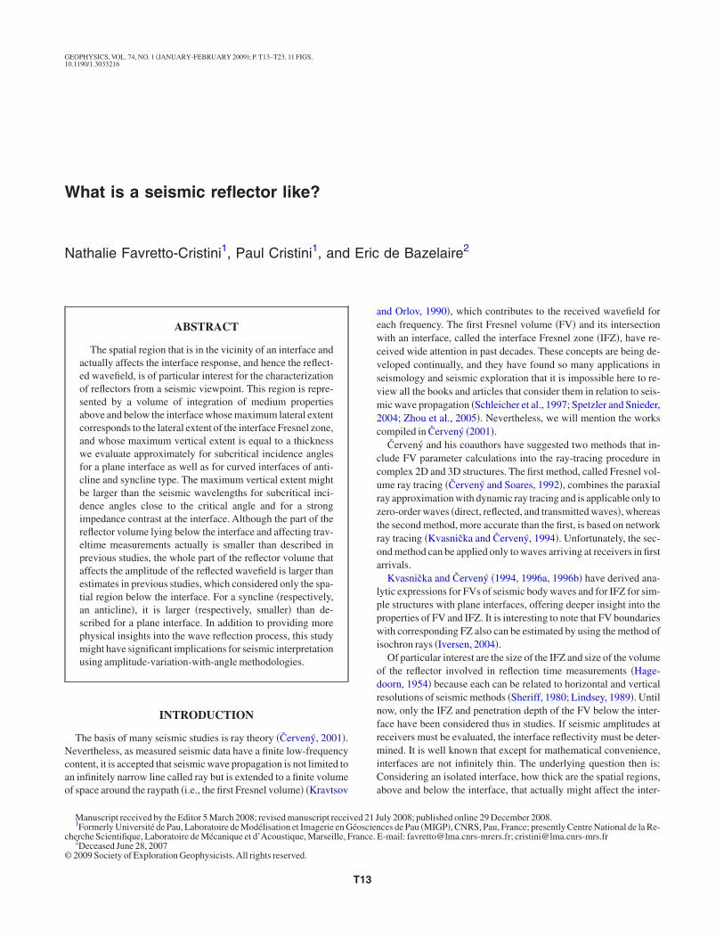
Figure 1. Repflection at thedence angle� 3000 m froterface curvatcline�. Veloci� 2800 m/s,per and lowerangle is equalthe ellipsoidsthe text for moThe dashed lispecular reflecsection of thecline.
The IFZ is defined as the extent of intersection of the FV by the in-erface, which here is spherically shaped. Unlike the case of a planenterface �Kvasnička and Červený, 1996a�, the IFZ is not represent-d by an ellipse centered at the reflection point M when the source Snd receiver R are situated at the same distance from the interface.epending on whether the interface is of anticline or syncline type,
he IFZ alters in shape appropriately, and its size might not be deter-ined in the same way for both types. Following Hubral and Krey
1980�, the radius of the interface curvature Rint is positive if the in-
0S R
M
Syncline
Anticline
z = zM
x
z
F
θ
Offset
Offset
M
Syncline
Anticline
z = zM
θ
–2000 0 2000 4000
000 –500 0 –500 –1000
tion, in the xz-plane, of the Fresnel volume involved in the wave re-at a curved interface of anticline or syncline type under the inci-
5°. The source S and receiver R are situated at a distance zM
xy-plane tangent to the interface at the point M. The radius of the in-Rint � �5000 m �positive for the anticline, negative for the syn-
the upper and lower half-spaces are VP1 � 2000 m/s and VP2
tively, and the frequency f � 25 Hz. Seismic wavelengths in the up-aces then are �1 � 80 m and �2 � 112 m, respectively. The critical� 45.58°. �a� The Fresnel volume is given by the volume betweenlution with foci at S and R and located in the upper half-space �seeils�. �b� Focus on the Fresnel volume in the vicinity of the interfaces.ribes the isochron for the source-receiver pair �S,R� relative to theR. The interface Fresnel zone, characterized by the extent of inter-
l volume by the interfaces, is larger for the syncline than for the anti-
rface
rface
4000
–1
resentapoint M� � 3m theure isties ofrespechalf-spto � C
of revore detane desction SM
Fresne
tcst
Ipco�fmtoo
etvmIscb
ftfi
Rls
waz
wwqiIt
�
w
Tic
w
tidMqctiitzMp
posttiMct
sticwv
tsam
T16 Favretto-Cristini et al.
erface appears convex to the incident wave. The radius Rint then ishosen positive for an anticline and negative for a syncline. Thistudy extends the analysis by Lindsey �1989�, who considered onlyhe case of normal wave incidence onto the curved interface.
For Lindsey, the critical parameter that influences the size of theFZ for a syncline is the ratio between the depth zM of the reflectionoint M and radius of the interface curvature Rint. Note that the criti-al parameter actually is the ratio between the radius of curvature Riso
f the ellipsoid of revolution describing the isochrone for the pairS,R� relative to the specular reflection SMR and radius of the inter-ace curvature Rint, the radius Riso being equal to the depth zM for nor-al wave incidence. Depending on whether this ratio is less or larger
han unity, the size of the IFZ is defined as the extent of intersectionf the ellipsoid of revolution located at the distance �1/4 either abover below the plane z � zM by the syncline.
On the contrary, the size of the IFZ for an anticline is defined as thextent of intersection of the ellipsoid of revolution located at the dis-ance �1/4 below the plane z � zM by the anticline, whatever thealue of its radius of curvature Rint. For the sake of brevity, only theost relevant equations necessary for determining the size of the
FZ for an anticline are presented hereafter. Equations relative to theyncline can be derived easily from equations relative to the anti-line by replacing the �positive� radius of the anticline curvature Rint
y the �negative� radius of the syncline curvature Rint.First we define the maximum lateral semiextent xmax of the IFZ
ollowing the x-axis in the xz-plane. In this plane, the anticline withhe curvature center C��0,zM � Rint� is represented by a circle de-ned by
x2 � �z � �zM � Rint��2 � Rint2 . �5�
eplacing the variable x by its expression obtained from the formu-ation of the ellipsoid of revolution, equation 4, and keeping only theign � in the term �zM /cos � � �1/4�2,
x2 � a2�1 �z2
b2� , �6�
here a � zM /cos � � �1/4 and b � �a2 � zM2 tan2 � �1/2, we obtain
n equation of the second degree in the unknown z whose solutions1 and z2 are
z1,2 �zM � Rint � �1/2
1 �a2
b2
, �7�
here � � �zM � Rint�2 � �1 � a2/b2��a2 � zM�zM � 2Rint�� is al-ays positive. Keeping only the solution z1 or z2 for which the ine-uality 1 � z2/b2 �0 is satisfied, and hence for which the variable xs positive, we deduce the maximum lateral semiextent xmax of theFZ following the x-axis in the plane of incidence from equation 6 sohat
xmax � a�1 �z1,2
2
b2 1/2
. �8�
In the yz-plane, the ellipsoid of revolution located at the distance1/4 below the plane z � zM is reduced to a circle defined by
y2 � z2 � b2, �9�
hereas the anticline is a circle defined by
y2 � �z � �zM � Rint��2 � Rint2 . �10�
he maximum lateral semiextent ymax of the IFZ following the y-axisn the yz-plane, i.e., in the direction perpendicular to the plane of in-idence, then is given by the intersection of these two circles,
ymax � �b2 � zM ��1
4� zM
cos ��
�1
8��zM
� Rint��1�21/2, �11�
here the quantity in the square root bracket is always positive.The characteristics xmax and ymax of the IFZ at the surface of the an-
icline depend on the position of the source-receiver pair and on thencidence angle � of the ray SM. The IFZ becomes larger in the inci-ence plane than in the transverse plane as the angle � increases.oreover, larger portions of the interface are involved for low-fre-
uency than for high-frequency components of the wavefield. Theharacteristics xmax and ymax of the IFZ also depend on the radius ofhe interface curvature Rint. For the anticline, the IFZ becomes largern the incidence plane than in the transverse plane as the radius of thenterface curvature Rint increases. For sufficiently great radius Rint,he IFZ for the anticline is identical to the IFZ for the plane interface� zM. It is represented by an ellipse centered at the reflection pointwhose in-plane semiaxis xmax and transverse semiaxis ymax are ex-
ressed as �Kvasnička and Červený, 1996a�
xmax � ymax�1 �zM
2 tan2 �
� zM
cos ��
�1
4�2
�1/2
, ymax
� �1
2� zM
cos ��
�1
8��1/2
. �12�
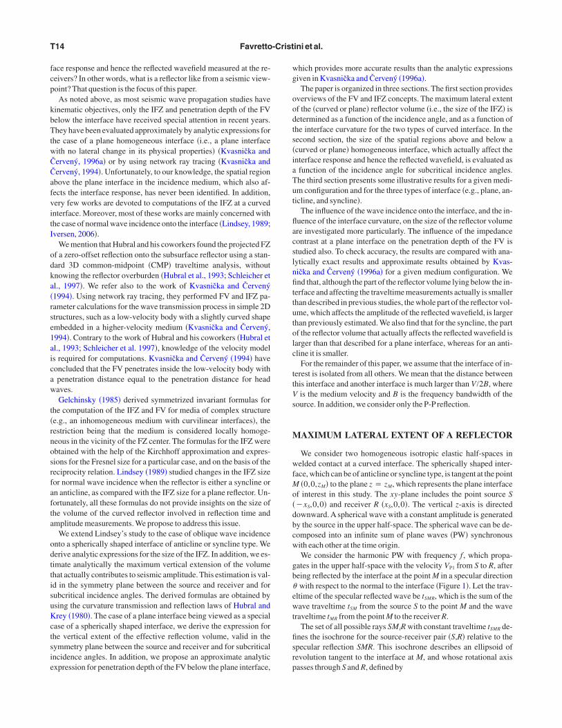
Here, we must clarify some important points. Use is made in manyapers of the classical representation of the FV, which is an ellipsoidf revolution with foci located at the receiver R and at the imageource S� situated symmetrically to the source S on the other side ofhe plane interface �Figure 2�. This representation, mainly based onransmission considerations, is suitable to account for heterogene-ties of the medium body located in the vicinity of the rays SM and
R, whereas the FV representation we use is more appropriate to ac-ount for heterogeneities of the interface, as it is connected strictly tohe wave reflection process.
Moreover, unlike the classical one, this representation allows in atraightforward manner the definition of volumes above and belowhe interface, which characterize the reflector. The following sections focused on this definition. Note that the two FV representations areomplementary and must be combined if wave propagation in mediaith heterogeneities in the medium body and at the interface is in-estigated.
MAXIMUM VERTICAL EXTENTOF A REFLECTOR
It is well known that the FV of the reflected wave is not limited byhe interface, but penetrates across the interface in the lower half-pace �Hagedoorn, 1954�. The penetration depth can be evaluatedpproximately in an analytic way following traveltime measure-ents �Kvasnička and Červený, 1996a� or in a numerical way, using
ndeisc
�
K
cwwtddtfvtm
wv
fztta
z
TpTppwttstt�
a
at
See the
What is a seismic reflector like? T17
etwork ray tracing �Kvasnička and Červený, 1994�. We propose toerive analytically, in a straightforward manner, an approximatexpression for the penetration depth of the FV across the curvednterface, valid in the plane of symmetry between S and R and forubcritical incidence angles. This new expression provides more ac-urate results than those obtained by Kvasnička and Červený.
The curvature transmission law described in Hubral and Krey1980, p. 43�,
2 � K1VP2
VP1� cos �
cos � ��2
�Kint
cos � ��VP2
VP1
cos �
cos � �� 1� , �13�
onnects the curvature K2 of the transmittedavefront to the curvature K1 of the incidentavefront and to the interface curvature Kint. The
ransmission angle � � is connected to the inci-ence angle � through Snell’s law, and VP2
enotes the velocity in the lower half-space. Inhe case of a curved interface, because the inter-ace curvature Kint is different from zero, the cur-ature transmission law, equation 13, becomes inerms of radii of curvature R2 and R1 of the trans-
itted and incident wavefronts, respectively,
1
R2�
1
R1
VP2
VP1� cos �
cos � ��2
�1
Rint cos � ��VP2
VP1
cos �
cos � �� 1� ,
�14�
here Rint denotes the radius of the interface cur-ature.
By substituting the radii of curvature R1 and R2
or their respective expressions zM /cos � andS�/cos � �, we get the position zS� of the new ficti-ious source-receiver pair �S�,R�� with respect tohe plane z � zM, as a function of the incidencengle � ,
S�
�zMVP1 cos3� �
VP2 cos3 � �zM
Rint
�VP2 cos��VP1 cos� ��.
�15�
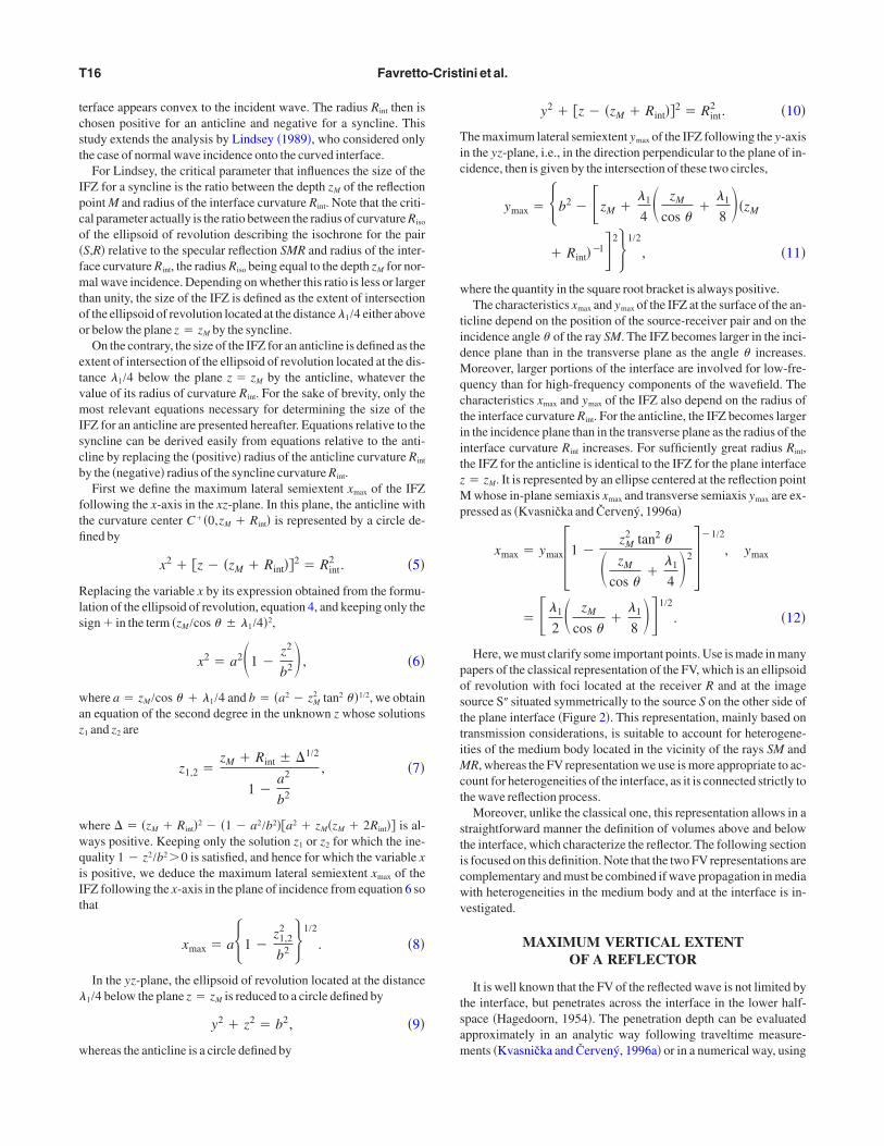
he pair �S�,R�� can be viewed as an image of theair �S,R� for the transmission process �Figure 3�.hat means that this fictitious source-receiverair provides the same wavefront curvature as theair �S,R�. Unlike the real transmission process,hich involves the upper and lower half-spaces,
he wavefront relative to �S�,R�� propagates en-irely in the lower half-space as if the upper half-pace did not exist. This procedure is similar tohe well-known procedure applied for the reflec-ion process, which consists of replacing the pairS,R� by its mirror image �S�,R�� �Figure 2�.
0
1000
2000
3000
4000
5000
6000
Dep
th(m
)
Figure 2. Reprflection at thesource S and rclassical reprefoci located atassociated witbetween the emore details�.
0
1000
2000
3000
4000
–4000
Dep
th(m
)
Figure 3. Repwave reflectiotious source-rviewed as anwavefront curper half-space
As above, by considering the ellipsoid of revolution with foci S�nd R� tangent to the plane z � zM at M �Figure 3�,
x2
� zS�
cos � ��2 �
y2 � z2
zS�2 � 1 � 0, �16�
nd the new ellipsoids that bound the FV associated with the reflec-ion S�MR�,
0S R
S'' R''
M Interface z = zM
x
z
θ
0 –2000 0 2000 4000
Offset (m)
tions, in the xz-plane, of the Fresnel volume involved in the wave re-M at the plane interface under the incidence angle � � 35°. Ther R are situated at a distance zM � 3000 m from the interface. Theon of the Fresnel volume is based on the ellipsoid of revolution withat the mirror image S�.Another representation of the Fresnel volumeflection SMR is given by the volume located in the upper half-space
ds of revolution with foci at S and R �see the text and Figure 1 forlegend of Figure 1 for medium properties.
0
M
S R
S' R'
Interface z = zM
x
z
θ'
000 –2000 –1000 0 –1000 –2000 –3000 –4000
Offset (m)
tion, in the xz-plane, of the Fresnel volume involved in the fictitiouspoint M at a plane interface under the incidence angle � �. The ficti-pair �S�,R�� located at a distance zS� from the interface plane can be
of the pair �S,R� for the transmission process. It provides the sameas �S,R� and propagates entirely in the lower half-space, as if the up-t exist. See the legend of Figure 1 for medium properties.
–400
esentapoint
eceivesentatiR andh the rellipsoi
–3
resentan at theeceiverimagevaturedid no
itt
mvleRaeNpt
ttaaotgDa�
trnta�
t
b
Befi�
tpptawmotaca
parpma�
tef
FxatmhdSac
T18 Favretto-Cristini et al.
x2
� zS�
cos � ��
�2
4�2 �
y2 � z2
� zS�
cos � ��
�2
4�2
� zS�2 tan2 � �
� 1
� 0, �17�
t is straightforward to evaluate approximately the maximum pene-ration depth D2, in the lower half-space, of the FV associated withhe specular reflection SMR,
D2 � � zS�
cos � ��
�2
4�2
� zS�2 tan2 � ��1/2
� zS�
� �zS�2
��2zS�
2 cos � ��
�22
16�1/2
� zS�. �18�
Because this expression is evaluated locally in the plane of sym-etry between S and R and for subcritical incidence angles � , it is
alid whatever the radius of the interface curvature Rint. Neverthe-ess, the expression for the position zS� of the fictitious pair �S�,R��,quation 15, differs following the radius of the interface curvature
int. The penetration depth out of the plane of symmetry between Snd R also can be evaluated in the same way from the envelope of thellipsoids of revolution with foci S� and R� moving along caustics.evertheless, for postcritical incidence angles, we cannot define theenetration depth of the FV below the interface by using the curva-ure transmission law, because total reflection occurs.
Note that equation 18 provides only approximate evaluation ofhe actual penetration depth of the FV below the interface becausehe derivation based upon the curvature transmission law of Hubralnd Krey �1980� does not take into account the fact that the incidencengle for the penetrating rays is not identical to the incidence anglef the central specular reflected ray. Expansion of equation 18 showshat for the values of the incidence angle � close to zero, and then forreat position zS�, the first-order approximation to penetration depth
2 with respect to 1/zS�2 ��2zS�/2 cos � � � �2/8� corresponds to the
pproximation given by equation 38 in Kvasnička and Červený1996a�,
D2 ��2
4 cos � �. �19�
Following the same reasoning, it seems clear that a region abovehe interface in the upper half-space also contributes to the interfaceesponse, and hence to the reflected wavefield. The maximum thick-ess D1 of this region can be evaluated in the plane of symmetry be-ween S and R and for subcritical incidence angles � in the same ways above, the pair �S�,R�� being viewed as a mirror image of the pairS,R� with respect to the plane z � zM �Figure 2�,
D1 � �zS�2
��1zS�
2 cos ��
�12
16�1/2
� zS�. �20�
We must determine the position zS� of the pair �S�,R��. The curva-ure reflection law in Hubral and Krey �1980, p. 43�,
K2 � K1 �2Kint
cos �, �21�
ecomes, in terms of radii of curvature R2 and R1,
1
R2�
1
R1�
2
Rint cos �. �22�
y substituting the radii of curvature R1 and R2 for their respectivexpressions zM /cos � and zS�/cos � , we get the position zS� of the newctitious source-receiver pair �S�,R�� with respect to the plane z
zM, as a function of the incidence angle � ,
zS� �zMRint cos2 �
2zM � Rint cos2 �. �23�
For the case of a plane interface, the radius of the interface curva-ure Rint tends to infinity, and the position zS� is equal to zM. Unlike theenetration depth D2, we can evaluate exactly the thickness D1 for alane interface, in the plane of symmetry between S and R, whateverhe incidence angle � , except for grazing angles. We also can evalu-te exactly the distance D1 out of the plane of symmetry in the sameay as above because the caustics along which the foci S� and R�
ove are degenerate and then are reduced to points. Unlike the casef the plane interface, however, we no longer can evaluate exactlyhe thickness D1 above a curved interface for subcritical incidencengles � in the plane of symmetry between S and R, because theaustics along which the foci S� and R� move are no longer degener-te and thus are not reduced to points.
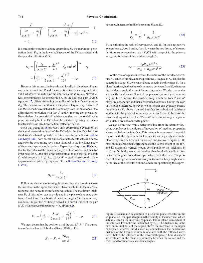
We can define now what a reflector is like from the seismic view-oint. A reflector is a volume of integration of medium propertiesbove and below the interface. This volume is represented by spatialegions with the maximum thicknesses D1 and D2 evaluated in thelane of symmetry between the source and receiver �Figure 4�. Itsaximum lateral extent corresponds to the lateral extent of the IFZ,
nd its maximum vertical extent corresponds to the thickness DD1 � D2. In this work, we consider that the elastic media in con-
act are homogeneous and isotropic, which is an ideal case. The pres-nce of heterogeneities or anisotropy in the media body might modi-y the size of the reflector volume, and more specifically the expres-
x
z
D1
D2Xmax
Planeinterface
igure 4. Schematic description of a seismic plane reflector in thez-plane, i.e., the spatial region in the vicinity of the interface, whichctually affects the interface response. The in-plane semiextent ofhe interface Fresnel zone is denoted by xmax. The distance D1 is theaximum thickness of the region above the interface in the upper
alf-space, whereas the distance D2 characterizes the penetrationistance of the Fresnel volume �associated with the reflected waveMR� below the interface in the lower half-space. These distancesre evaluated in the plane of symmetry between the source and re-eiver and for subcritical incidence angles.
stfl
fc�cta�Tatahr�
fiusfivtetp
cbwpssfluIoglmtctdcl�
trw
tp
wstp
st
legend
What is a seismic reflector like? T19
ions for the IFZ and thicknesses D1 and D2. It would be interestingo analyze the effect of anisotropy of the media on the size of the re-ector volume. Our future contributions will focus on this topic.
RESULTS AND DISCUSSION
To illustrate the theoretical derivations, two cases of curved inter-aces and one case of plane interface between elastic half-spaces arehosen. The source-receiver plane is located at a distance zM
3000 m from the plane tangent to the curved interfaces, whichan be of anticline or syncline type. The radius of the interface curva-ure Rint is equal to �5000 m. It is positive for annticline and negative for a syncline. The plane z
zM represents the plane interface of interest.he velocities of the upper and lower half-spacesre VP1 � 2000 m/s and VP2 � 2800 m/s, respec-ively. The frequency f being chosen is 25 Hz,nd seismic wavelengths in the upper and loweralf-spaces then are �1 � 80 m and �2 � 112 m,espectively. The critical angle is equal to � C
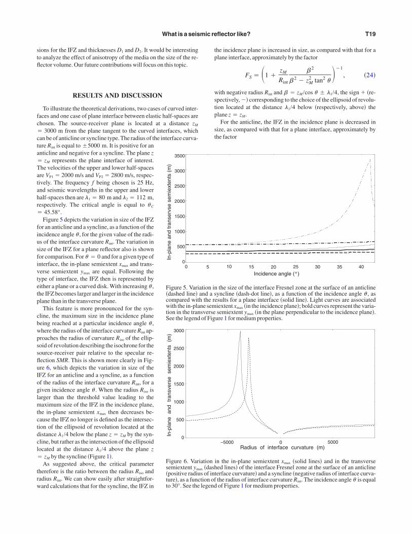
45.58°.Figure 5 depicts the variation in size of the IFZ
or an anticline and a syncline, as a function of thencidence angle � , for the given value of the radi-s of the interface curvature Rint. The variation inize of the IFZ for a plane reflector also is shownor comparison. For � � 0 and for a given type ofnterface, the in-plane semiextent xmax and trans-erse semiextent ymax are equal. Following theype of interface, the IFZ then is represented byither a plane or a curved disk. With increasing � ,he IFZ becomes larger and larger in the incidencelane than in the transverse plane.
This feature is more pronounced for the syn-line, the maximum size in the incidence planeeing reached at a particular incidence angle � ,here the radius of the interface curvature Rint ap-roaches the radius of curvature Riso of the ellip-oid of revolution describing the isochrone for theource-receiver pair relative to the specular re-ection SMR. This is shown more clearly in Fig-re 6, which depicts the variation in size of theFZ for an anticline and a syncline, as a functionf the radius of the interface curvature Rint, for aiven incidence angle � . When the radius Riso isarger than the threshold value leading to the
aximum size of the IFZ in the incidence plane,he in-plane semiextent xmax then decreases be-ause the IFZ no longer is defined as the intersec-ion of the ellipsoid of revolution located at theistance �1/4 below the plane z � zM by the syn-line, but rather as the intersection of the ellipsoidocated at the distance �1/4 above the plane z
zM by the syncline �Figure 1�.As suggested above, the critical parameter
herefore is the ratio between the radius Riso andadius Rint. We can show easily after straightfor-ard calculations that for the syncline, the IFZ in
0
In-p
lane
and
tran
serv
sese
mie
xten
ts(m
)
3500
3000
2500
2000
1500
1000
500
0
Figure 5. Vari�dashed line�compared witwith the in-plation in the tranSee the legend
In-p
lane
and
tran
sver
sese
mie
xten
ts(m
)
3000
2500
2000
1500
1000
500
0
Figure 6. Varsemiextent ym
�positive radiuture�, as a functo 30°. See the
he incidence plane is increased in size, as compared with that for alane interface, approximately by the factor
FS � �1 �zM
Rint
� 2
� 2 � zM2 tan2 �
��1
, �24�
ith negative radius Rint and � � zM /cos � � �1/4, the sign � �re-pectively, � corresponding to the choice of the ellipsoid of revolu-ion located at the distance �1/4 below �respectively, above� thelane z � zM.
For the anticline, the IFZ in the incidence plane is decreased inize, as compared with that for a plane interface, approximately byhe factor
10 15 20 25 30 35 40
Incidence angle ( )
the size of the interface Fresnel zone at the surface of an anticlineyncline �dash-dot line�, as a function of the incidence angle � , as
esults for a plane interface �solid line�. Light curves are associatediextent xmax �in the incidence plane�; bold curves represent the varia-semiextent ymax �in the plane perpendicular to the incidence plane�.ure 1 for medium properties.
–5000Radius of interface curvature (m)
0 5000
in the in-plane semiextent xmax �solid lines� and in the transverseed lines� of the interface Fresnel zone at the surface of an anticline
terface curvature� and a syncline �negative radius of interface curva-the radius of interface curvature Rint. The incidence angle � is equalof Figure 1 for medium properties.
5
ation inand a sh the rne semsverseof Fig
iationax �dashs of intion of
wad
mcyrtdt
tc
wtic
ofpc
FasS
FpeČ
T20 Favretto-Cristini et al.
FA � �1 �zM
Rint
a2
a2 � zM2 tan2 �
��1
, �25�
ith positive radius Rint and a � zM /cos � � �1/4. The factors FS
nd FA tend to those given in Lindsey �1989� when the wave inci-ence is normal to the interface.
Similar conclusions can be drawn for the variation in the maxi-um semiextent ymax of the IFZ in the transverse plane for the anti-
line and syncline. The critical parameter that influences the lengthmax is the ratio between the radius of curvature Riso of the ellipsoid ofevolution describing the isochrone for the source-receiver pair rela-ive to the specular reflection SMR in the transverse plane �i.e., theepth zM of the reflection point M� and radius of the interface curva-ure Rint. For the anticline �respectively, the syncline�, the IFZ in the
0 5 10 15 20 25 30
Incidence angle ( )
Pen
etra
tion
dept
h(m
)
90
80
70
60
50
40
30
20
igure 7. Variation in the penetration depth D2 as a function of the inn interface of anticline �light curves� or syncline �bold curves� typeults provided by our approximation �dashed lines� with the exact soee the legend of Figure 1 for medium properties.
0 5 10 15 20 25 30
Incidence angle ( )
100
90
80
70
60
50
40
30
20
Pen
etra
tion
dept
h(m
)
igure 8. Variation in the penetration depth D2 as a function of the inclane interface. Comparison of results provided by our approximatioxact solution �solid line� and results predicted by the approximatioervený �1996a� �dash-dot line�.
ransverse plane is decreased �respectively, increased� in size, asompared with that for a plane interface, approximately by the factor
F � �1 �zM
Rint��1
, �26�
ith positive radius Rint for the anticline and negative radius Rint forhe syncline. Note in Figure 6 that when the value of the radius of thenterface curvature Rint tends to infinity, the size of the IFZ for aurved interface tends to that for a plane interface.
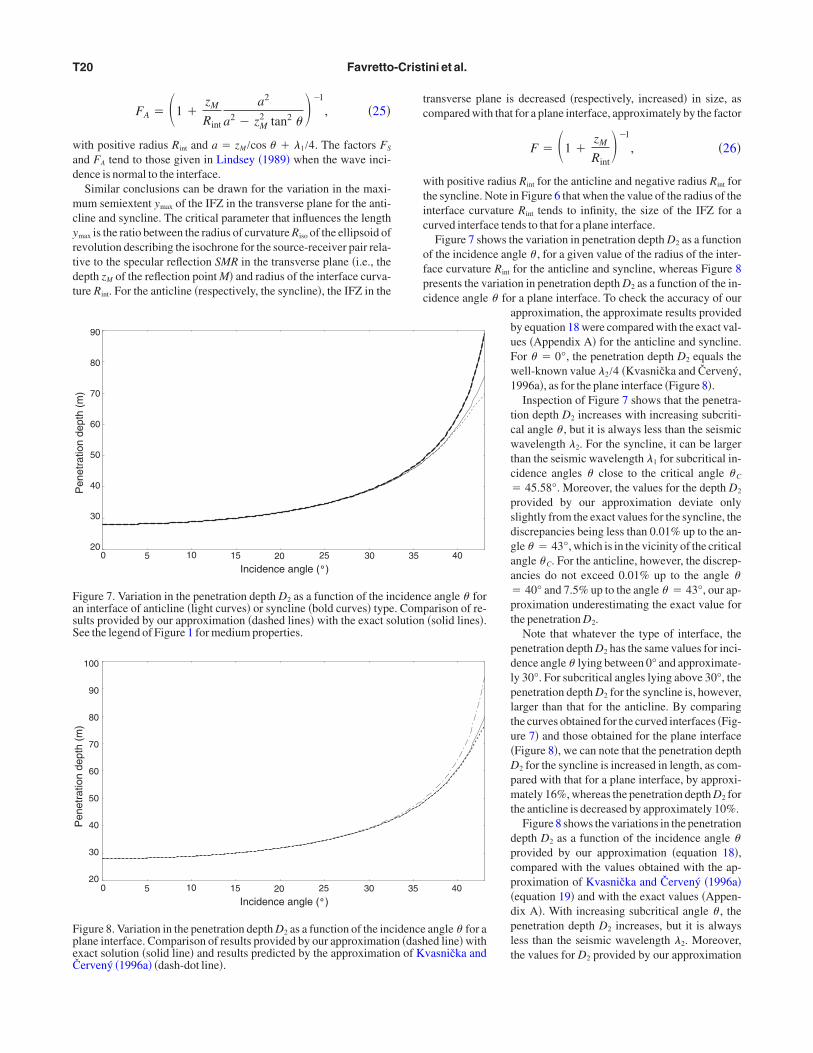
Figure 7 shows the variation in penetration depth D2 as a functionf the incidence angle � , for a given value of the radius of the inter-ace curvature Rint for the anticline and syncline, whereas Figure 8resents the variation in penetration depth D2 as a function of the in-idence angle � for a plane interface. To check the accuracy of our
approximation, the approximate results providedby equation 18 were compared with the exact val-ues �Appendix A� for the anticline and syncline.For � � 0°, the penetration depth D2 equals thewell-known value �2/4 �Kvasnička and Červený,1996a�, as for the plane interface �Figure 8�.
Inspection of Figure 7 shows that the penetra-tion depth D2 increases with increasing subcriti-cal angle � , but it is always less than the seismicwavelength �2. For the syncline, it can be largerthan the seismic wavelength �1 for subcritical in-cidence angles � close to the critical angle � C
� 45.58°. Moreover, the values for the depth D2
provided by our approximation deviate onlyslightly from the exact values for the syncline, thediscrepancies being less than 0.01% up to the an-gle � � 43°, which is in the vicinity of the criticalangle � C. For the anticline, however, the discrep-ancies do not exceed 0.01% up to the angle �� 40° and 7.5% up to the angle � � 43°, our ap-proximation underestimating the exact value forthe penetration D2.
Note that whatever the type of interface, thepenetration depth D2 has the same values for inci-dence angle � lying between 0° and approximate-ly 30°. For subcritical angles lying above 30°, thepenetration depth D2 for the syncline is, however,larger than that for the anticline. By comparingthe curves obtained for the curved interfaces �Fig-ure 7� and those obtained for the plane interface�Figure 8�, we can note that the penetration depthD2 for the syncline is increased in length, as com-pared with that for a plane interface, by approxi-mately 16%, whereas the penetration depth D2 forthe anticline is decreased by approximately 10%.
Figure 8 shows the variations in the penetrationdepth D2 as a function of the incidence angle �provided by our approximation �equation 18�,compared with the values obtained with the ap-proximation of Kvasnička and Červený �1996a��equation 19� and with the exact values �Appen-dix A�. With increasing subcritical angle � , thepenetration depth D2 increases, but it is alwaysless than the seismic wavelength �2. Moreover,the values for D2 provided by our approximation
40
e angle � forparison of re-�solid lines�.
40
angle � for aed line� with
vasnička and
35
cidenc. Comlution
35
idencen �dashn of K

dtt�
tsfatfifNtgcitde
nstccpcAft
tfaeadDb�ncal
vaertlrtliar
i
htwitwiwcr
wlti
What is a seismic reflector like? T21
eviate only slightly from the exact values. The discrepancies be-ween them do not exceed 0.44% up to the angle � � 40° and 4% upo the angle � � 43°, which is in the vicinity of the critical angle � C
45.58°.On the contrary, the discrepancies between values for D2 given by
he approximation of Kvasnička and Červený �1996a� and the exactolution strongly increase with increasing angle � , more particularlyor angles above 30°. For � � 43° the discrepancies exceed 23%.Asconsequence, the part of a reflector below the interface, which ac-
ually affects the interface response and hence the reflected wave-eld, is smaller than previous estimates. This conclusion has beenound to come true whatever the medium configuration chosen.evertheless, for a given incidence angle � the discrepancies be-
ween the values for D2 provided by our approximation and thoseiven by the approximation of Kvasnička and Červený �1996a� de-rease with decreasing impedance contrast at thenterface, as shown in Figure 9. For instance, forhe impedance contrast equal to 1.2 and the inci-ence angle � � 30°, the discrepancy does notxceed 0.27%.
Figure 10 displays the variation in the thick-ess D1 above the interface in the upper half-pace, as a function of the incidence angle � , forhe given value of the radius of the interfaceurvature Rint for the anticline and syncline. Toheck the accuracy of our approximation, the ap-roximate results provided by equation 20 wereompared with the exact values �Appendix B�.pproximate values for D1 deviate only slightly
rom the exact values, the discrepancies betweenhem lying below 0.05% up to the angle � � 43°.
Figure 10 also depicts the variation in the dis-ance D1, as a function of the incidence angle � ,or a plane interface. In this case, as mentionedbove, the distance D1 provided by equation 20 isvaluated exactly. Whatever the type of interfacend for the normal wave incidence �� � 0°�, theistance D1 equals the value �1/4. The thickness1 increases with increasing incidence angles � ,ut it is always less than the seismic wavelength1 and penetration depth D2. Moreover, the thick-ess D1 is not much influenced by the interfaceurvature, the dicrepancies between the curvesssociated with the syncline and anticline beingess than 1%.
In this work, we have identified the zone in theicinity of a �plane or curved� interface that actu-lly affects the interface reflectivity, and we havestablished the spatial limits of this effectiveeflector volume, which merits further investiga-ion. Although these spatial limits might vary fol-owing the properties of the bulk media in contactesulting, for instance, from anisotropy or fromhe presence of heterogeneities, defining theseimits for an ideal case �e.g., homogeneous andsotropic media in contact� enables us to fix ideasnd provide a road map for future applications toeal media.
In addition to providing more physical insightsnto the wave reflection process, our study could
1.0
Pen
etra
tion
dept
h(m
)140
120
100
80
60
40
20
0
Figure 9. Variplane interfacapproximatioČervený �199
Max
imum
thic
knes
s(m
)
0
28
27
26
25
24
23
22
21
20
Figure 10. Varfor an interfacterface �dottedwith the exact
ave significant implications for seismic interpretation using ampli-ude-variation-with-angle �AVA� methodologies. On the one hand,hen amplitude measurements are considered, we must evaluate the
nterface reflectivity by considering the effective reflector volumehat actually affects it, and by accounting for heterogeneities locatedithin this volume. More specifically, we must select heterogene-
ties whose characteristic length, along with their spatial distributionithin the reflector volume, might interact with properties of the in-
ident wave, so as to derive a model of the effective behavior of theeflector volume.
A structural description of multiscaled heterogeneities locatedithin the reflector volume must be considered, therefore, as a pre-
iminary step toward the modeling of the interface response. Our fu-ure contributions will focus on this topic. However, we specify thatn the absence of heterogeneity located within the reflector volume,
Impendance contrast
1.2 1.3 1.5 1.6 1.7 1.8 1.91.4
the penetration depth D2 as a function of the impedance contrast at ae incidence angle � � 30°. Comparison of results provided by ourline� with results predicted by the approximation of Kvasnička and
shed line�.
10 15 20 25 30 35 40
Incidence angle ( )
in the maximum thickness D1 as a function of the incidence angle �icline �light curves� or syncline �bold curves� type and for a plane in-Comparison of results provided by our approximation �dashed line�n �solid line�. See the legend of Figure 1 for medium properties.
1.1
ation ine for thn �solid6a� �da
5
iatione of antline�.
solutio
wsesmssZtt
ttlcpoitgwal
tfiwamm
pTtvmtbifll
iCsc
Bfst
c
cAtFsDfs
w
o
wl
s�o
w
Ftssv
T22 Favretto-Cristini et al.
e must account for only the IFZ for modeling the interface re-ponse. In a previous work �Favretto-Cristini et al., 2007�, we point-d out the consequences of ignoring the IFZ in forward modeling ofeismic wave reflection. More specifically, for wide-angle AVAethodologies and near the critical incidence angle, the geometric
preading compensation no longer is sufficient to reduce the point-ource amplitudes to plane-wave �PW� amplitudes predicted byoeppritz equations. The additional application of the IFZ concept
o the PW theory is necessary to obtain the reflected P-wave ampli-udes measured at receivers.
These results have significant implications for seismic interpreta-ion using amplitudes:Assuming that theAVAcurves correspondingo real measured data might be described well by the PW theoryeads to biased estimations of the media properties, even in the idealase of homogeneous isotropic media. Our present work is focusedrecisely on this particular aspect and will be reported later. On thether hand, when only traveltime measurements are considered, fornstance for locating reflectors in the media, there is no need to definehe region above the interface with the thickness D1, because this re-ion is already included in the classical representation of the FV,hich is the ellipsoid of revolution with foci located at the receiver R
nd at the image source S� �Figure 2�. In this case, only the region be-ow the interface with the thickness D2 must be considered.
CONCLUSION
We have identified the zone in the vicinity of an interface that ac-ually affects the interface reflectivity and hence the reflected wave-eld. Our work extends previous studies to the case of the obliqueave incidence onto a plane interface, or onto a curved interface of
nticline or syncline type, between two homogeneous and isotropicedia. We have derived analytic expressions for evaluating approxi-ately the spatial limits of the effective reflector volume.A comparison with exact results has shown that our expressions
rovide more accurate results than those given in previous works.he effective reflector volume has its maximum lateral extent equal
o the lateral extent of the interface Fresnel zone, and its maximumertical extent equal to a thickness that might be larger than the seis-ic wavelength of the incident wave for great incidence angles close
o the critical angle. Although the part of the reflector volume lyingelow the interface and affecting traveltime measurements actuallys smaller than described in previous studies, the whole part of the re-ector volume affecting the amplitude of the reflected wavefield is
arger than previous estimates.
ACKNOWLEDGMENTS
The work reported here is the result of a fruitful collaboration dur-ng many years between us, Nathalie Favretto-Cristini and Paulristini, and our late friend Dr. Eric de Bazelaire. We consider our-
elves extremely fortunate to have had the opportunity to worklosely with a scientist of Dr. de Bazelaire’s caliber.
We gratefully appreciate the careful reviews by J. P. Lindsey, B.ednar,A. Stovas, and associate editor D. Draganov. We thank them
or their valuable comments and suggestions to improve the manu-cript. We also thank Jacques Blanco for his encouragement and en-husiasm for this work.
The work was supported in part by theAgence Nationale de la Re-herche �ANR� under the EMSAPCO2 project.
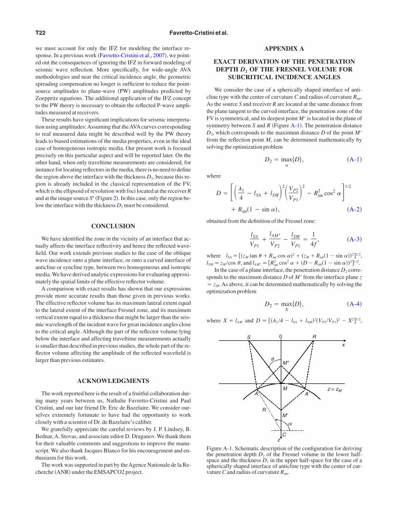
APPENDIX A
EXACT DERIVATION OF THE PENETRATIONDEPTH D2 OF THE FRESNEL VOLUME FOR
SUBCRITICAL INCIDENCE ANGLES
We consider the case of a spherically shaped interface of anti-line type with the center of curvature C and radius of curvature Rint.s the source S and receiver R are located at the same distance from
he plane tangent to the curved interface, the penetration zone of theV is symmetrical, and its deepest point M� is located in the plane ofymmetry between S and R �Figure A-1�. The penetration distance
2, which corresponds to the maximum distance D of the point M�rom the reflection point M, can be determined mathematically byolving the optimization problem
D2 � max
�D� , �A-1�
here
D � ��1
4� lSA � lSM�2�VP2
VP1�2
� Rint2 cos2 �1/2
� Rint�1 � sin � , �A-2�
btained from the definition of the Fresnel zone:
lSA
VP1�
lAM�
VP2�
lSM
VP1�
1
4f, �A-3�
here lSA� ��zM tan � �Rint cos �2� �zM �Rint�1�sin ��2�1/2,SM �zM /cos � , and lAM�� �Rint
2 cos2 � �D�Rint�1�sin ��2�1/2.In the case of a plane interface, the penetration distance D2 corre-
ponds to the maximum distance D of M� from the interface plane zzM. As above, it can be determined mathematically by solving the
ptimization problem
D2 � maxX
�D� , �A-4�
here X � lAM and D � ���1/4 � lSA � lSM�2�VP2/VP1�2 � X2�1/2,
S 0 R
M"
M
M'
Cz
A
R
A'
x
z = zM
θ
�
igure A-1. Schematic description of the configuration for derivinghe penetration depth D2 of the Fresnel volume in the lower half-pace and the thickness D1 in the upper half-space for the case of apherically shaped interface of anticline type with the center of cur-ature C and radius of curvature R .
int
o�
moe
w
o�i
B
Č
Č
F
G
H
H
H
I
—
K
K
K
—
—
L
S
S
S
Z
What is a seismic reflector like? T23
btained from the definition of the Fresnel zone with lSA
��zM tan � � X�2 � zM2 �1/2 and lAM� � �X2 � D2�1/2.
APPENDIX B
EXACT DERIVATION OF THE MAXIMUMTHICKNESS D1 FOR SUBCRITICAL INCIDENCE
ANGLES
Considering the configuration depicted in Figure A-1, the maxi-um thickness D1, which corresponds to the maximum distance D�
f the point M� from the reflection point M, can be determined math-matically by solving the optimization problem
D1 � max
�D�� , �B-1�
here
D� � ��1
4� lSA � lSM�2
� Rint2 cos2 �1/2
� Rint�1
� sin � , �B-2�
btained from the definition of the FZ with lAM� � �Rint2 cos2
�D � Rint�1 � sin ��2�1/2, the distances lSM and lSA being givennAppendix A.
REFERENCES
orn, M., and E. Wolf, 1999, Principles of optics, 7th exp. ed.: CambridgeUniversity Press.
ervený, V., 2001, Seismic ray theory: Cambridge University Press.
ervený, V., and J. Soares, 1992, Fresnel volume ray tracing: Geophysics,57, 902–915.
avretto-Cristini, N., P. Cristini, and E. de Bazelaire, 2007, Influence on theInterface Fresnel zone on the reflected P-wave amplitude modeling: Geo-physical Journal International, 171, 841–846.
elchinsky, B., 1985, The formulae for the calculation of the Fresnel zonesor volumes: Journal of Geophysics, 57, 33–41.
agedoorn, J. G., 1954, A process of seismic reflection interpretation: Geo-physical Prospecting, 2, 85–127.
ubral, P., and T. Krey, 1980, Internal velocities from seismic reflection timemeasurements: SEG.
ubral, P., J. Schleicher, M. Tygel, and C. Hanitzch, 1993, Determination ofFresnel zones from traveltime measurements: Geophysics, 58, 703–712.
versen, E., 2004, The isochron ray in seismic modeling and imaging: Geo-physics, 69, 1053–1070.—–, 2006, Amplitude, Fresnel zone, and NMO velocity for PP and SS nor-mal-incidence reflections: Geophysics, 71, no. 2, W1–W14.
napp, R., 1991, Fresnel zones in the light of broadband data: Geophysics,56, 354–359.
ravtsov, Y., and Y. Orlov, 1990, Geometrical optics of inhomogeneous me-dia: Springer-Verlag, Springer Series on Wave Phenomena.
vasnička, M., and V. Červený, 1994, Fresnel volumes and Fresnel zones incomplex laterally varying structures: Journal of Seismic Exploration, 3,215–230.—–, 1996a, Analytical expressions for Fresnel volumes and interfaceFresnel zones of seismic body waves: Part 1 — Direct and unconverted re-flected waves: Studia Geophysica et Geodetica, 40, 136–155.—–, 1996b, Analytical expressions for Fresnel volumes and interfaceFresnel zones of seismic body waves: Part 2 — Transmitted and convertedwaves. Head waves: Studia Geophysica et Geodetica, 40, 381–397.
indsey, J., 1989, The Fresnel zone and its interpretative significance: TheLeading Edge, 8, 33–39.
chleicher, J., P. Hubral, M. Tygel, and M. Jaya, 1997, Minimum aperturesand Fresnel zones in migration and demigration: Geophysics, 62,183–194.
heriff, R., 1980, Nomogram for Fresnel-zone calculation: Geophysics, 45,968–972.
petzler, J., and R. Snieder, 2004, The Fresnel volume and transmittedwaves:Atutorial: Geophysical Journal International, 69, 653–663.
hou, Y., F. Dahlen, G. Nolet, and G. Laske, 2005, Finite-frequency effects inglobal surface-wave tomography: Geophysical Journal International, 163,
1087–1111.