Westinghouse Electric Co., Response for Additional ... · Westinghouse Westinghouse Electric...
28
Westinghouse Westinghouse Electric Company Nuclear Power Plants P.O. Box 355 Pittsburgh, Pennsylvania 15230-0355 USA 412-374-6206 724-940-8505 [email protected] U.S. Nuclear Regulatory Commission ATTENTION: Document Control Desk Washington, D.C. 20555 Direct tel: Direct fax: e-mail: Your ref: Docket No. 52-006 Ourref: DCPNRC_002994 August 2, 2010 Subject: AP 1000 Response to Request for Additional Information (SRP 23) Westinghouse is submitting a response to the NRC request for additional information (RAI) on SRP Section 23. This RAI response is submitted in support of the AP1000 Design Certification Amendment Application (Docket No. 52-006). The information included in this response is generic and is expected to apply to all COL applications referencing the AP 1000 Design Certification and the AP 1000 Design Certification Amendment Application. Enclosure 1 provides the response for the following RAI(s): RAI-DCP-CN01-SBP-COLP-01 Questions or requests for additional information related to the content and preparation of this response should be directed to Westinghouse. Please send copies of such questions or requests to the prospective applicants for combined licenses referencing the AP 1000 Design Certification. A representative for each applicant is included on the cc: list of this letter. Very truly yours, Robert Sisk, Manager Licensing and Customer Interface Regulatory Affairs and Strategy /Enclosure 1. Response to Request for Additional Information on SRP Section 23 (i-C) 06161jb.doc 8/2/2010 6:51 PM
Transcript of Westinghouse Electric Co., Response for Additional ... · Westinghouse Westinghouse Electric...

Westinghouse Westinghouse Electric CompanyNuclear Power PlantsP.O. Box 355Pittsburgh, Pennsylvania 15230-0355USA
U.S. Nuclear Regulatory CommissionATTENTION: Document Control DeskWashington, D.C. 20555
Direct tel:Direct fax:
e-mail:
Your ref: Docket No. 52-006Ourref: DCPNRC_002994
August 2, 2010
Subject: AP 1000 Response to Request for Additional Information (SRP 23)
Westinghouse is submitting a response to the NRC request for additional information (RAI) on SRPSection 23. This RAI response is submitted in support of the AP1000 Design Certification AmendmentApplication (Docket No. 52-006). The information included in this response is generic and is expected toapply to all COL applications referencing the AP 1000 Design Certification and the AP 1000 DesignCertification Amendment Application.
Enclosure 1 provides the response for the following RAI(s):
RAI-DCP-CN01-SBP-COLP-01
Questions or requests for additional information related to the content and preparation of this responseshould be directed to Westinghouse. Please send copies of such questions or requests to the prospectiveapplicants for combined licenses referencing the AP 1000 Design Certification. A representative for eachapplicant is included on the cc: list of this letter.
Very truly yours,
Robert Sisk, ManagerLicensing and Customer InterfaceRegulatory Affairs and Strategy
/Enclosure
1. Response to Request for Additional Information on SRP Section 23
(i-C)
06161jb.doc 8/2/2010 6:51 PM

DCPNRC_002994August 2, 2010
Page 2 of 2
cc: D. JaffeE. McKennaB. AndersonM. WentzelT. SpinkP. HastingsR. KitchenA. MonroeP. JacobsC. PierceE. SchmiechG. ZinkeR. GrumbirS. Ritterbusch
U.S. NRCU.S. NRCU.S. NRCU.S. NRCTVADuke PowerProgress EnergySCANAFlorida Power & LightSouthern CompanyWestinghouseNuStart/EntergyNuStartWestinghouse
1E1E1E1E1E1E1E1E1E1E1E1E1E1E
0616jb.doc 8/2/2010 6:51 PM

DCPNRC_002994August 2, 2010
ENCLOSURE 1
Response to Request for Additional Information on SRP Section 23
06161jb.doc 8/2/2010 6:51 PM

AP1000 TECHNICAL REPORT REVIEW
Response to Request For Additional Information (RAI)
RAI Response Number: RAI-DCP-CN01 -SBP-COLP-01Revision: 0
Question:
The NRC has completed its review of the final information on proposed changes for the AP1 000Design Control Document (DCD), Revision 18, dated April 26, 2010. Based on a review of theinformation that was provided, additional information is needed to address the followingconsiderations related to change number 1 for the potable water system:
1. A figure was not provided so the staff is unable to ensure the adequacy of the potablewater control room boundary isolation provisions that are proposed. Provide a diagramshowing the safety related portions of the potable water system, including valvedesignations and sizes, line designations and sizes, loop seal dimensions, and otherassociated equipment. Show the location of these components with relation to the maincontrol room, and indicate the boundary between safety related and non-safety relatedequipment. Include this figure in the DCD.
2. A loop seal is proposed to maintain main control room (MCR) isolation in until manualpotable water isolation valves can be closed by the operators. Describe the basis forsizing the loop seal and in particular, what the loop seal dimensions are and how theywere determined. Explain how the loop seal will be kept full by the design or include aCOL item to ensure that the loop seal will be properly maintained during plant operation.Include this information in the DCD.
3. The DCD needs to be revised to provide a description of the safety related portions ofthe potable water system in Tier 1, including a functional diagram that shows the relativelocations of important components and the dimensions of the loop seal. Tier 1inspections, tests, analyses, and acceptance criteria (ITAAC) also need to beestablished to ensure that the as-built configuration of the safety related portions of thepotable water system satisfy design requirements. Likewise, the description in Tier 2Section 9.2.5 needs to be revised to reflect the changes that are being made to thepotable water system.
4. Additional information is needed to explain how the vacuum breaker satisfies singlefailure considerations.
5. Explain the event sequence that establishes the minimum response time for manuallyshutting the potable water isolation valves. Explain how a failure of potable water pipingwill be identified by the operators and what indications will be used to initiate the manualaction. Explain how the operator manual action can be reliably and correctlyaccomplished within the required time period. Please confirm the manual operatoractions have been included in the Human Reliability Analysis. State specifically whetherthe manual actions are "Risk Important Human actions." These considerations need tobe addressed and the DCD needs to be revised to include this information.
RAI-DCP-CN01 -SBP-coLP-e1
lo ~etingousePage 1 of 25

AP1000 TECHNICAL REPORT REVIEW
Response to Request For Additional Information (RAI)
6. The impact of potable water pipe failure in the control room on equipment important tosafety needs to be addressed for both water spray/flooding effects and theconsequences of non-safety-related parts of the potable water system impacting controlroom equipment due to failure of non-seismic supports. If these considerations arealready addressed in the DCD, provide reference to where this information is provided.
7. The initial test program needs to be revised to include provisions for testing the potablewater isolation design features.
8. Additional information is needed to explain how the AP1 000 Technical Specificationsaddress operability requirements for the potable water system safety-related isolationfunction.
9. Tier 2 Section 3.2 of the DCD, Revision 17, indicates that the sanitary drainage systemis classified as "Class P. This classification is used for plumbing equipment andcomplies with the National Plumbing Code. Based on the information provided in Tier 2Section 9.2.6 of the DCD, it is unclear if the sanitary drain piping and associated ventspenetrate the control room boundary and if provisions similar to those that wereestablished for the potable water system are also needed for the sanitary drainagesystem and vents. Additional information is needed to explain how the integrity of thecontrol room boundary is ensured for any sanitary drain penetrations and vents thatexist. Similarly, describe to what extent any other vents and drains and other fluidsystems penetrate the control room boundary and explain how the integrity of the controlroom is ensured for these other penetrations.
* WestinghouseRAI-DCP-CN01-SBP-COLP-01
Page 2 of 25
AP1000 TECHNICAL REPORT REVIEW
Response to Request For Additional Information (RAI)
Westinghouse Response:
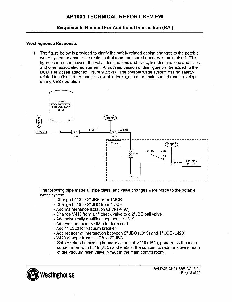
1. The figure below is provided to clarify the safety-related design changes to the potablewater system to ensure the main control room pressure boundary is maintained. Thisfigure is representative of the valve designations and sizes, line designations and sizes,and other associated equipment. A modified version of this figure will be added to theDCD Tier 2 (see attached Figure 9.2.5-1). The potable water system has no safety-related functions other than to prevent in-leakage into the main control room envelopeduring VES operation.
2" L319
V497 V418
JBC JCE
1" L320 V498
SPW3SMCRFIXTURES
- - - - - - - - - - - - - - - - - - - -
The following pipe material, pipe class, and valve changes were made to the potablewater system:
- Change L418 to 2" JBE from 1"JCB- Change L319 to 2" JBC from 1 "JCE- Add maintenance isolation valve (V497)- Change V418 from a 1" check valve to a 2"JBC ball valve- Add seismically qualified loop seal to L319- Add vacuum relief V498 after loop seal- Add 1" L320 for vacuum breaker- Add reducer at intersection between 2" JBC (L319) and 1" JCE (L420)- V420 change from 1" JCB to 2" JBC- Safety-related (seismic) boundary starts at V418 (JBC), penetrates the main
control room with L319 (JBC) and ends at the concentric reducer downstreamof the vacuum relief valve (V498) in the main control room.
* Westinghouse
RAI-DCP-CNO I-SBP-COLP-01Page 3 of 25

AP1000 TECHNICAL REPORT REVIEW
Response to Request For Additional Information (RAI)
2. The potable water system loop seal is added to maintain main control room (MCR)isolation in the event that the non-seismic PWS piping would break during an event. Theloop seal supports the 1/8-inch VES pressurization of the main control room andprovides sufficient time for the operators to manually close either of the redundantpotable water isolation valves. In the event that the non-safety-related portion of thepotable water supply line would rupture following a seismic event, the water remaining inthe loop seal would be lost relatively slowly only due to evaporation. This relatively slowprocess provides sufficient time for operators to take manual action to locate and isolatesmall amounts of air leakage that might begin to occur as the water evaporates overtime.
The basis for sizing the loop seal was determined by the requirements of the MainControl Room Emergency Habitability System (VES). The VES shall be capable ofmaintaining pressure in the MCR of at least 1/8-inchWater Gauge between the MCRpressure boundary and the surrounding areas. The loop seal is routed so that it has adepth of 6-inches. This depth provides assurance that the loop seal will perform itsfunction to maintain the MCR pressure boundary while the VES is in operation followinga seismic event. The potable water tank on the elevation above the MCR area (el. 135'-7") provides water to the fixtures in the MCR area and is always in service, therefore thedaily operation of the main control room potable water fixtures keeps the loop seal full bydesign prior to the initiation of a plant event.
3. DCD Tier 1 changes are provided below. Previously, RAI-SRP 6.4-SPCV-03 transmittedchanges to the non-radioactive ventilation system ITAAC tables. These changescaptured design changes to the potable water, sanitary drainage, and waste watersystems to ensure the main control room envelope. In addition, the markup of Tier 1subsection 2.7.1 in this RAI (provided below) now implements all the design changes tothe potable water system, as well as including the sanitary drainage and waste watersystem changes necessary to provide the main control room envelope integrity.
4. The function of the vacuum breaker is to help ensure that a break in the non-safety-related potable water supply piping, during a seismic event, would not cause water tosiphon from the loop seal. Vacuum breakers, which are classified in a common groupwith pressure and vacuum relief devices by the ASME Code as discussed in DCDSection 3.9.6.2.2, are spring-loaded relief valves and are active components included inDCD Tables 3.9-12 and 3.9-16.
These pressure / vacuum relief devices are not required to consider single activefailures, consistent with the DCD approach for active failures as discussed in DCDSections 15.0.12 and 6.3.2.5.1. This design approach is consistent with theimplementation of single vacuum relief device (vacuum breaker RCS-PL-V01 OA or-V01OB in DCD Figure 5.1-5, Sheet 2 of 3) in each Automatic Depressurization Systemdischarge header for the Reactor Coolant System, or the implementation of a singlepressure relief device (relief valve VES-PL-V040A, -V040B, -V041A, or -V041 B in DCDFigure 6.4-2, Sheet 1 of 2) for each of the four VES air storage banks. In both of these
RAI-DCP-CNO1 -SBP-COLP-01tnhuse Page 4 of 25

AP1000 TECHNICAL REPORT REVIEW
Response to Request For Additional Information (RAI)
examples, single active failure is not considered as a credible postulated failure for eithera pressure or vacuum relief device. This same approach is applicable for this additionalvacuum relief device added to the PWS supply line.
5. The safety-related potable water loop seal assures main control room pressureboundary integrity after a design basis event. Since a seismic event does not occursimultaneously with another design basis event, there are no radiological conditions orother hazards such as toxic gases that would challenge MCR habitability. (For example,PGS hydrogen tank leakage has been evaluated and does not challenge MCRhabitability or present a flammability hazard if it leaks following a seismic event.) VESactuation occurs only assuming the sustained loss of electrical power, and for thissituation, the design basis for VES actuation is to provide breathable air for the MCRoccupants, which also helps to prevent the buildup of C02.
The pressurization aspect, while part of the design basis, is not the primary priority forthis event without an external challenge to MCR habitability. The potable water systemloop seal is designed to remain intact following a seismic event and has been designedto provide al/8-inch water seal in conjunction with the vacuum breaker operation,following an event.
Following longer-term evaporation of the water in the loop seal, or for a deterministicbeyond-design-basis approach simply considering the loop seal to not be available, theMCR occupants still have a supply of breathable air for 72 hours and the MCR wouldremain habitable. The operators would be alerted of a loss of air through the loop sealpiping by the low differential pressure alarm for the MCR and would take actions tolocate the source of leakage of the MCR pressurization air flow. The operators wouldcorrect it by closing either of the redundant potable water manual isolations (since singlefailure of manual isolation valves is assumed as discussed in DCD Section 15.0.12).
Therefore, even with a slight loss of pressurization, which is not expected for designbasis events, the MCR occupants still have breathable air and a slight loss ofpressurization while they are identifying and correcting this situation. This situation isnot a challenge to habitability because there are no radiological or toxic chemicalhazards that would exist for a seismic event.
6. DCD Tier 2 Section 3.4.1.2.2 Internal Flooding discusses a postulated pipe and potablewater storage tank (150 gallons) rupture in the Auxiliary Building Level 5 (Elevation 135'-.3"). This section states "Water from fire fighting, postulated pipe, or potable waterstorage tank (150 gallons) ruptures in the main mechanical HVAC equipment roomsdrains to the turbine building via floor drains or to the annex building via flow under thedoors. Therefore, no significant accumulation of water occurs in this room. Floorpenetrations are sealed and a 6 inch platform is provided at the elevator and stairwellsuch that flooding in these rooms does not propagate to levels below."
RAI-DeP-iNn0-SBP-CaLP-o1
I Westinghouse Pg f2

AP1000 TECHNICAL REPORT REVIEW
Response to Request For Additional lnformation (RAI)
The potable water system penetrates the main control area and serves the main controlarea kitchen and bathroom areas. The 1" non-seismic lines of the potable water linesare limited to the kitchen and bathroom areas. DCD Tier 2 Subsection 3.4.1.2.2.2Auxiliary Building Flooding Events, Auxiliary Building Level 4 (117'-6") states: "While themain control room kitchen and restroom are provided with potable water, the lines are 1-inch and smaller, and are not evaluated for pipe ruptures." In addition, there are nosafety-related components that would be adversely affected by a rupture of the 1" non-seismic potable water system piping in the MCR kitchen and bathroom areas.
7. The initial test program including the design changes to the potable water systemensures the integrity of the MCR pressure boundary. In the Main Control RoomEmergency Habitability System General Test Acceptance Criteria and Methodssubsection of the DCD (Tier 2 Subsection 14.2.9.1.6), it is stated that the properoperation of safety-related valves is verified by the performance of baseline in-servicetests as described in subsection 3.9.6. Subsection 3.9.6 "Inservice Testing of Pumpsand Valves" further directs that Table 3.9-16 identifies the components subject to thepreservice and the inservice test program. DCD Tier 2 Subsection 14.2.9.1.6 and Table3.9-16 have been updated below.
8. This information was transmitted to the NRC by RAI-SRP 6.4-SPCV-03. Subsection3.7.6 of the Technical Specifications addresses the Main Control Room HabitabilitySystem (VES) and has been updated to include the safety-related isolation function ofthe potable water system.
9. RAI-SRP 6.4-SPCV-03 provided additional information regarding the AP1000 MainControl Room (MCR) boundary. The response included DCD markups relating to theMCR habitability. In addition to the nuclear island nonradioactive ventilation system(VBS) and the main control room emergency habitability system (VES), the sanitarydrain system (SDS), the potable water system (PWS) and the waste water system(WWS) also penetrate the MCR boundary. Isolation of each of these system'spenetrations through MCR boundary are described in RAI-SRP 6.4-SPCV-03 and asmodified in this response.
Design Control Document (DCD) Revision:
See DCD markups below.
PRA Revision:
None
Technical Report (TR) Revision:
FRAI-DCP-CN01 -SBP-COLP-01Westinghouse IPage 6 of 25

AP1000 TECHNICAL REPORT REVIEW
Response to Request For Additional Information (RAI)
None
* WestinghouseRAI-DCP-CN01 -SBP-COLP-01
Page 7 of 25
AP1000 TECHNICAL REPORT REVIEW
Response to Request For Additional Information (RAI)
Tier 1 changes:
2.7.1 Nuclear Island Nonradioactive Ventilation System
Design Description
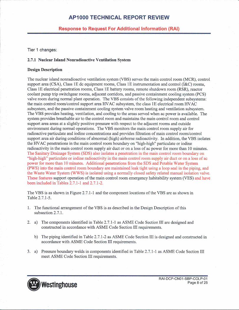
The nuclear island nonradioactive ventilation system (VBS) serves the main control room (MCR), controlsupport area (CSA), Class 1 E dc equipment rooms, Class 1 E instrumentation and control (I&C) rooms,Class 1E electrical penetration rooms, Class 1E battery rooms, remote shutdown room (RSR), reactorcoolant pump trip switchgear rooms, adjacent corridors, and passive containment cooling system (PCS)valve room during normal plant operation. The VBS consists of the following independent subsystems:the main control room/control support area HVAC subsystem, the class 1E electrical room HVACsubsystem, and the passive containment cooling system valve room heating and ventilation subsystem.The VBS provides heating, ventilation, and cooling to the areas served when ac power is available. Thesystem provides breathable air to the control room and maintains the main control room and controlsupport area areas at a slightly positive pressure with respect to the adjacent rooms and outsideenvironment during normal operations. The VBS monitors the main control room supply air forradioactive particulate and iodine concentrations and provides filtration of main control room/controlsupport area air during conditions of abnormal (high) airborne radioactivity. In addition, the VBS isolatesthe HVAC penetrations in the main control room boundary on "high-high" particulate or iodineradioactivity in the main control room supply air duct or on a loss of ac power for more than 10 minutes.The Sanitary Drainage System (SDS) also isolates a penetration in the main control room boundary on"high-high" particulate or iodine radioactivity in the main control room supply air duct or on a loss of acpower for more than 10 minutes. Additional penetrations from the SDS and Potable Water System(PWS) into the main control room boundary are maintained leak tight using a loop seal in the piping, andthe Waste Water System (WWS) is isolated using a normally closed safety related manual isolation valve.These features support operation of the main control room emergency habitability system (VES) and havebeen included in Tables 2.7.1-1 and 2.7.1-2.
The VBS is as shown in Figure 2.7.1-1 and the component locations of the VBS are as shown inTable 2.7.1-5.
1. The functional arrangement of the VBS is as described in the Design Description of thissubsection 2.7.1.
2. a) The components identified in Table 2.7.1-1 as ASME Code Section HI are designed andconstructed in accordance with ASME Code Section I1 requirements.
b) The piping identified in Table 2.7.1-2 as ASME Code Section HI is designed and constructed inaccordance with ASME Code Section 1I requirements.
3. a) Pressure boundary welds in components identified in Table 2.7.1-1 as ASME Code Section IIImeet ASME Code Section mH requirements.
RAI-DCP-CN01 -SBP-COLP-01Westinghouse Page 8 of 25

AP1000 TECHNICAL REPORT REVIEW
Response to Request For Additional Information (RAI)
b) Pressure boundary welds in piping identified in Table 2.7.1-2 as ASME Code Section I11 meetASME Code Section Im requirements.
4. a) The components identified in Table 2.7.1-1 as ASME Code Section mI retain their pressureboundary integrity at their design pressure.
b) The piping identified in Table 2.7.1-2 as ASME Code Section HI retains its pressure boundaryintegrity at its design pressure.
5. The seismic Category I equipment identified in Table 2.7.1-1 can withstand seismic design basis loadswithout loss of safety function.
6. a) The Class lE components identified in Table 2.7.1-1 are powered from their respective Class 1Edivision.
b) Separation is provided between VBS Class 1E divisions, and between Class 1E divisions andnon-Class 1E cable.
7. The VBS provides the safety-related function to isolate the pipes that penetrate the MCR pressureboundary.
8. The VBS provides the following nonsafety-related functions:
a) The VBS provides cooling to the MCR, CSA, RSR, and Class 1E electrical rooms.
b) The VBS provides ventilation cooling to the Class 1E battery rooms.
c) The VBS maintains MCR and CSA habitability when radioactivity is detected.
d) The VBS provides ventilation cooling via the ancillary equipment in Table 2.7.1-3 to the MCRand the division B&C Class IE I&C rooms.
9. Safety-related displays identified in Table 2.7.1-1 can be retrieved in the MCR.
10. a) Controls exist in the MCR to cause the remotely operated valves identified in Table 2.7.1-1 toperform their active functions.
b) The valves identified in Table 2.7.1-1 as having protection and safety monitoring system (PMS)control perform their active safety function after receiving a signal from the PMS.
11. After loss of motive power, the valves identified in Table 2.7.1-1 assume the indicated loss of motivepower position.
12. Controls exist in the MCR to cause the components identified in Table 2.7.1-3 to perform the listedfunction.
13. Displays of the parameters identified in Table 2.7.1-3 can be retrieved in the MCR.
RAI-DCP-CN01-SBP-COLP-01G Westinghouse Page 9 of 25

AP1000 TECHNICAL REPORT REVIEW
Response to Request For Additional Information (RAI)
14. The background noise level in the MCR and RSR does not exceed 65 dB(A) when the VBS isoperating.
Inspections, Tests, Analyses, and Acceptance Criteria
Table 2.7.1-4 specifies the inspections, tests, analyses, and associated acceptance criteria for the VBS.
* Westinghouse
RAI-DCP-CN01-SBP-COLP-01Page 10 of 25.

AP1000 TECHNICAL REPORT REVIEW
Response to Request For Additional Information (RAI)
TABLE 2.7.1-1
ASME Class 1E/ Loss ofCode Remotely Qual. for Safety- Motive
Section Seismic Operated Harsh Related Control Active PowerEquipment Name Tag No. III Cat. I Valve Envir. Display PMS/DAS(1) Function Position
MCR Supply Air VBS-PL-V186 Yes Yes Yes Yes/No Yes Yes/No Transfer ClosedIsolation Valve (Valve Closed
Position)
MCR Supply Air VBS-PL-V187 Yes Yes Yes Yes/No Yes Yes/No Transfer ClosedIsolation Valve (Valve Closed
Position)
MCR Return Air VBS-PL-V188 Yes Yes Yes Yes/No Yes Yes/No Transfer ClosedIsolation Valve (Valve Closed
Position)
MCR Return Air VBS-PL-VI 89 Yes Yes Yes Yes/No Yes Yes/No Transfer ClosedIsolation Valve (Valve Closed
Position)
MCR Exhaust Air VBS-PL-V190 Yes Yes Yes Yes/No Yes Yes/No Transfer ClosedIsolation Valve (Valve Closed
Position)
MCR Exhaust Air VBS-PL-V 191 Yes Yes Yes Yes/No Yes Yes/No Transfer ClosedIsolation Valve (Valve Closed
Position)
O WestinghouseRAI-DCP-CN01 -SBP-COLP-01
Page 11 of 25

AP1000 TECHNICAL REPORT REVIEW
Response to Request For Additional Information (RAI)
TABLE 2.7.1-1
ASME Class 1E/ Loss ofCode Remotely Qual. for Safety- Motive
Section Seismic Operated Harsh Related Control Active PowerEquipment Name Tag No. III Cat. I Valve Envir. Display PMS/DAS") Function Position
PWS MCR Isolation PWS-PL-V418 Yes Yes No -/- No No TransferValve Closed
PWS MCR Isolation PWS-PL-V420 Yes Yes No -1- No No TransferValve Closed
PWS MCR Vacuum PWS-PL-V498 Yes Yes No -/- No No TransferRelief Open
MCR SDS (Vent) SDS-PL-V001 Yes Yes Yes Yes/No Yes Yes/No Transfer As IsIsolation Valve (Valve Closed
Position)
MCR SDS (Vent) SDS-PL-V002 Yes Yes Yes Yes/No Yes Yes/No Transfer As IsIsolation Valve (Valve Closed
Position)
MCR WWS Isolation WWS-PL-V506 Yes Yes No -/- No NoValve
1. DAS = diverse actuation system
* WestinghouseRAI-DCP-CN01-SBP-COLP-01
Page 12 of 25

AP1000 TECHNICAL REPORT REVIEW
Response to Request For Additional Information (RAI)
TABLE 2.7.1-2
ASME Code Leak FunctionalLine Name Line Number Section Ill Before Break Capability Required
Main Control Room VBS-L311 Yes No NoSupply
Main Control Room VBS-L312 Yes No NoExhaust
Main Control Room VBS-L313 Yes No NoToilet Exhaust
Main Control Room SDS-PL-L035 Yes No NoSanitary Vent Line
Main Control Room SDS-PL-L030 Yes No NoSanitary Drain Line
Main Control Room PWS-PL-L319 Yes No NoWater Line
Main Control Room PWS-PL-L320 Yes No NoWater Line
Main Control Room WWS-PL-L808 Yes No NoWaste Water Line
Main Control Room WWS-PL-L851 Yes No NoWater Line
*WestinghouseRAI-DCP-CN01-SBP-COLP-01
Page 13 of 25

AP1000 TECHNICAL REPORT REVIEW
Response to Request For Additional Information (RAI)
TABLE 2.7.1-4
INSPECTIONS, TESTS, ANALYSES, AND ACCEPTANCE CRITERIA
Design Commitment Inspections, Tests, Analyses Acceptance Criteria
1. The functional arrangement Inspection of the as-built system The as-built VBS conforms withof the VBS is as described in will be performed. the functional arrangementthe Design Description of this described in the Designsubsection 2.7.1 Description of this
subsection 2.7.1.
2.a) The components identified Inspection will be conducted of The ASME Code Section mIIin Table 2.7.1-1 as ASME Code the as-built components as design reports exist for the as-Section III are designed and documented in the ASME design built components identified inconstructed in accordance with reports. Table 2.7.1-1 as ASME CodeASME Code Section III Section III.requirements.
2.b) The piping identified in Inspection will be conducted of The ASME code Section IIITable 2.7.1-2 as ASME Code the as-built components as design reports exist for theSection ImI is designed and documented in the ASME design as-built piping identified inconstructed in accordance with reports. Table 2.7.1-2 as ASME CodeASME Code Section III Section III.requirements.
3.a) Pressure boundary welds Inspection of the as-built A report exists and concludesin components identified in pressure boundary welds will be that the ASME Code Section IIITable 2.7.1-1 as ASME Code performed in accordance with the requirements are met forSection III meet ASME Code ASME Code Section Ill. nondestructive examination ofSection EIl requirements. pressure boundary welds.
3.b) Pressure boundary welds Inspection of the as-built A report exists and concludesin piping identified in Table pressure boundary welds will be that the ASME Code Section III2.7.1-2 as ASME Code Section performed in accordance with the requirements are met forIII meet ASME Code Section ASME Code Section III. nondestructive examination ofIII requirements. pressure boundary welds.
4.a) The components identified A pressure test will be performed A report exists and concludesin Table 2.7.1-1 as ASME Code on the components required by that the results of the pressureSection III retain their pressure the ASME Code Section III to be test of the components identifiedboundary integrity at their pressure tested. in Table 2.7.1-1 as ASME Codedesign pressure. Section III conform with the
requirements of the ASME CodeSection III.
O WestinghouseRAI-DCP-CN01-SBP-COLP-01
Page 14 of 25

AP1000 TECHNICAL REPORT REVIEW
Response to Request For Additional Information (RAI)
TABLE 2.7.1-4
INSPECTIONS, TESTS, ANALYSES, AND ACCEPTANCE CRITERIA
Design Commitment Inspections, Tests, Analyses Acceptance Criteria
4.b) The piping identified in A pressure test will be performed A report exists and concludesTable 2.7.1-2 as ASME Code on the piping required by the that the results of the pressureSection III retains its pressure ASME Code Section mI to be test of the piping identified inboundary integrity at its design pressure tested. Table 2.7.1-2 as ASME Codepressure. Section III conform with the
requirements of the ASME Code
Section III.
5. The seismic Category I i) Inspection will be performed i) The seismic Category Iequipment identified in to verify that the seismic equipment identified inTable 2.7.1-1 can withstand Category I equipment identified Table 2.7.1-1 is located on theseismic design basis loads in Table 2.7.1-1 is located on the Nuclear Island.without loss of safety function. Nuclear Island.
ii) Type tests, analyses, or a ii) A report exists and concludescombination of type tests and that the seismic Category Ianalyses of seismic Category I equipment can withstandequipment will be performed. seismic design basis loads
without loss of safety function.
iii) Inspection will be performed iii) A report exists andfor the existence of a report concludes that the as-installedverifying that the as-installed equipment including anchorageequipment including anchorage is seismically bounded by theis seismically bounded by the tested or analyzed conditions.tested or analyzed conditions.
6.a) The Class 1 E components Testing will be performed on the A simulated test signal exists atidentified in Table 2.7.1-1 are VBS by providing a simulated the Class 1E equipmentpowered from their respective test signal in each Class 1E identified in Table 2.7.1-1 whenClass lE division, division, the assigned Class 1E division is
provided the test signal.
6.b) Separation is provided See Tier 1 Material, Table 3.3-6, See Tier 1 Material, Table 3.3-6,between VBS Class IE item 7.d. item 7.d.divisions, and between Class 1Edivisions and non-Class 1Ecable.
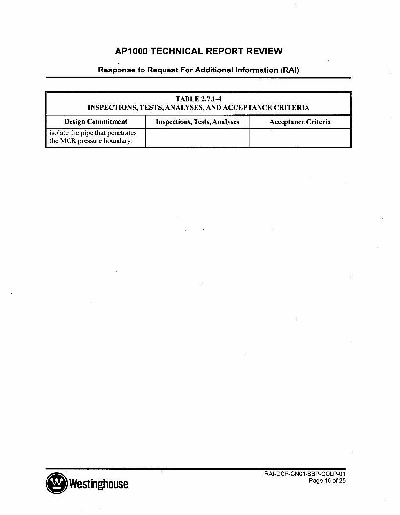
7. The VBS and SDS provides See item 10.b in this table. See item 10.b in this table.the safety-related function to
* WestinghouseRAI-DCP-CN01 -SBP-COLP-01
Page 15 of 25
AP1000 TECHNICAL REPORT REVIEW
Response to Request For Additional Information (RAI)
TABLE 2.7.1-4INSPECTIONS, TESTS, ANALYSES, AND ACCEPTANCE CRITERIA
Design Commitment Inspections, Tests, Analyses Acceptance Criteria
isolate the pipe that penetratesthe MCR pressure boundary.
O WestinghouseRAI-DCP-CN01-SBP-COLP-01
Page 16 of 25

AP1000 TECHNICAL REPORT REVIEW
Response to Request For Additional Information (RAI)
Tier 2 changes:
Table 3.2-3 (Sheet 14 of 65)
AP1000 CLASSIFICATION OF MECHANICAL ANDFLUID SYSTEMS, COMPONENTS, AND EQUIPMENT
Potable Water System (PWS) Location: VariousMoEPWS-PL-V4 18 PWS MCR Isolation Valve C I ASME 111-3PWS-PL-V420 PWS MCR Isolation Valve C I ASME 111-3PWS-PL-V498 PWS MCR Vacuum Relief C I ASME 111-3
Balance of system components are Class E
Table 3.9-12 (Sheet 2 of 7)
LIST OF ASME CLASS 1, 2, AND 3 ACTIVE VALVES
Valve No. Description Function(a)
Potable Water System
PWS-PL-V4 18 PWS MCR Isolation Valve 3
PWS-PL-V420 PWS MCR Isolation Valve 3
PWS-PL-V498 PWS MCR Vacuum Relief 3
*Westinghouse
RAI-DCP-CN01-SBP-COLP-01Page 17 of 25

AP1000 TECHNICAL REPORT REVIEW
Response to Request For Additional Information (RAI)
Table 3.9-16 (Sheet 7 of 23)
VALVE INSERVICE TEST REQUIREMENTS
Valve Safety- Inservice TestingTag Valve Related Safety ASME Class/ Type and
Number Description(") Type Missions Functions(2) IST Category Frequency IST Notes
PWS-PL- PWS MCR Manual Transfer Active Class 3 Exercise FullV418 Isolation Close Category B Stroke/2 years
Valve Maintain
Close
PWS-PL- PWS MCR Manual Transfer Active Class 3 Exercise FullV420 Isolation Close Category B Stroke/2 years
Valve Maintain
Close
PWS-PL- PWS MCR Relief Transfer Active Class 3 Vacuum Relief/2V498 Vacuum Open Category C Years
Relief
Table 3.11-1 (Sheet 21 of 50)
ENVIRONMENTALLY QUALIFIED ELECTRICAL AND MECHANICAL EQUIPMENT
OperatingEnvir. Time Qualification
AP1000 Zone Function Required ProgramDescription Tag No. (Note 2) (Note 1) (Note 5) (Note 6)
PWS MCR Isolation PWS-PL-V418 3 ISOL 5 min MPWS MCR Isolation PWS-PL-V420 3 ISOL 5 min MPWS MCR Vacuum Relief PWS-PL-V498 3 ISOL 5 min M
fWestinghouse
RAI-DCP-CN01-SBP-COLP-01Page 18 of 25

AP1000 TECHNICAL REPORT REVIEW
Response to Request For Additional Information (RAI)
Table 31.6-3 (Sheet 5 of 32)
LIST OF AP1000 SAFETY-RELATED ELECTRICALAND MECHANICAL EQUIPMENT NOT HIGH FREQUENCY SENSITIVE
AP1000
Description Tag Number Comment
PWS MCR Isolation PWS-PL-V418 2
PWS MCR Isolation PWS-PL-V420 2
PWS MCR Vacuum Relief PWS-PL-V498 2
DCD Tier 2 Subsection 9.2.5 has been updated and the changes were shown in RAI-SRP-6.4-SPCV-03 as shown below.
9.2.5 Potable Water System
9.2.5.1 Design Basis
The potable water system (PWS) is designed to furnish water for domestic use and humanconsumption. It complies with the following standards:
* Bacteriological and chemical quality requirements as referenced in EPA "NationalPrimary Drinking Water Standards," 40 CFR Part 141.
* The distribution of water by the system is in compliance with 29 CFR 1910,
Occupational Safety and Health Standards, Part 141.
9.2.5.1.1 Safety Design Basis
The potable water system penetrates the main control room envelope boundary. A safetyrelated loop seal in the PWS piping that penetrates the main control room envelope boundaryprevents in-leakage into the main control room envelope during VES operation.
9.2.5.1.2 Power Generation Design Basis
Potable water is supplied to provide a quantity of 50 gallons/person/day for the largestnumber of persons expected to be at the station during a 24-hour period during normalplant power generation or outages.
(I WestinghouseRAI-DCP-CN01-SBP-COLP-01
Page 19 of 25

AP1000 TECHNICAL REPORT REVIEW
Response to Request For Additional Information (RAI)
Water heaters provide a storage capacity equal to the probable hourly demand forpotable hot water usage and provide hot water for the main lavatory, shower areas, andother locations where needed.
" A minimum pressure of 20 psig is maintained at the furthermost point in the distributionsystem.
* No interconnections exist between the potable water system and any potentiallyradioactive system or any system using water for purposes other than domestic waterservice.
9.2.5.2 System Description
9.2.5.2.1 General Description
Classification of components and equipment for the potable water system is given inSection 3.2.
The source of water for the potable water system is a site-specific water system. The potablewater system consists of a distribution header around the power block, hot water storageheaters, and necessary interconnecting piping and valves. All other components of the potablewater system outside the power block are site-specific and will be addressed in accordancewith subsection 9.2.11.
9.2.5.2.2 Component Description
Hot Water Heaters
Electric immersion heating elements located inside the potable water hot water tank are usedto produce hot water. This hot water is routed to the shower and toilet areas and to otherplumbing fixtures and equipment requiring domestic hot water service. Point of use, inlineelectric water heating elements are used to generate hot water for the main control room andthe turbine building secondary sampling laboratory.
9.2.5.3 System Operation
Filtered water is supplied from a site-specific water source for the potable water distributionsystem.
The onsite water supply system will maintain an appropriate pressure throughout thedistribution system.
RAI-DCP-CNo1 -SBP-COLP-01tng0use Page 20 of 25

AP1000 TECHNICAL REPORT REVIEW
Response to Request For Additional Information (RAI)
Potable water is supplied to areas that have the potential to be contaminated radioactively.Where this potential for contamination exists, the potable water system is protected by areduced pressure zone type backflow prevention device.
No interconnections exist between the potable water system and any system using water forpurposes other than domestic water service including any potentially radioactive system. Thecommon supply from the onsite raw water system is designed to use an air gap to preventcontamination of the potable water system from other systems supplied by the raw watersystem.
9.2.5.4 Safety Evaluation
The potable water system has a safety-related function to prevent in-leakage into the maincontrol room envelope during VES operation. A loop seal in the safety-related PWS piping thatpenetrates the main control room envelope boundary prevents in-leakage into the main control roomenvelope.
9.2.5.5 Tests and Inspections
The potable water system is hydrostatically tested for leak-tightness in accordance with theUniform Plumbing Code. Inspection of the system is in compliance with the UniformPlumbing Code or governing codes having jurisdiction. The system is then disinfected,flushed with potable water, and placed in service. The presence of residual chlorine can beconfirmed through laboratory tests of samples at sampling points as required. Tests formicrobiological and bacteria presence in potable water are conducted periodically.
9.2.5.6 Instrumentation Applications
Thermostats, high-temperature limit controls, and temperature indication are installed on thepotable water system hot water tank. Thermostats and high-temperature limit controls areinstalled on the inline water heaters. Pressure regulators are employed in those parts of thedistribution system where pressure restrictions are imposed.
OWestinghouse
RAI-DCP-CN01-SBP-COLP-01Page 21 of 25

AP1000 TECHNICAL REPORT REVIEW
Response to Request For Additional Information (RAI)
Figure 9.2.5-1 Main Control Room Potable Water System Isolation
,ECas crcl7Rass E
V420 I" L320 V498
'jURES
L - - - - - - - - - - - - - - - -
O WestinghouseRAI-DCP-CN01 -SBP-COLP-01
Page 22 of 25

AP1000 TECHNICAL REPORT REVIEW
Response to Request For Additional Information (RAI)
14.2.9.1.6 Main Control Room Emergency Habitability System Testing
Purpose
The purpose of the main control room emergency habitability system testing is to verify thatthe as-installed components properly perform the safety-related functions described inSection 6.4, including the following:
* Provide sufficient breathable quality air to the main control room* Maintain the main control room at positive pressure* Provide passive cooling of designated equipment
In addition, the following safety-related functions performed by the nuclear islandnonradioactive ventilation system described in subsection 9.4.1 are tested:
* Provide isolation of the main control room from the surrounding areas and outsideenvironment during a design basis accident if the nuclear island nonradioactiveventilation system becomes inoperable.
* Monitor the radioactivity in the main control room normal air supply and provide signalsto isolate the incoming air and actuate the main control room emergency habitabilitysystem.
In addition, the following safety-related functions performed by the potable water systemdescribed in subsection 9.2.5, the sanitary drainage system described in subsection 9.2.6, andthe waste water system in subsection 9.2.9 are tested:
Provide isolation of the main control room from the surrounding areas and outside
environment during a design basis accident.
Prerequisites
The construction testing of the main control room habitability system has been successfullycompleted. The required preoperational testing of the compressed and instrument air system,Class 1 E electrical power and uninterruptible power supply systems, normal control roomventilation system, and other interfacing systems required for operation of the above systemsis available as needed to support the specified testing and system configurations. The maincontrol room air supply tanks are filled with air acceptable for breathing. The main controlroom construction is complete and its leak-tight barriers are in place.
General Test Acceptance Criteria and Methods
Performance of the main control room habitability system is observed and recorded during aseries of individual component and integrated system testing. The following testing
RAI-DCP-CNW1n-SBP-COLP-1Page 23 of 25
AP1000 TECHNICAL REPORT REVIEW
Response to Request For Additional Information (RAI)
demonstrates that the habitability system operates as specified in Section 6.4 and as specifiedin the appropriate design specifications:a) Proper operation of safety-related valves is verified by the performance of baseline
in-service tests as described in subsection 3.9.6.
b) Proper calibration and operation of safety-related and system readiness instrumentation,controls, actuation signals and interlocks is verified. This testing includes the following:
Air storage tank pressureRefill line connection pressureMain control room differential pressure
" Air supply line flow rate" Controls for the main control room pressure relief valves" Controls for the air supply isolation valves" Controls for the main control room air inlet isolation valves" Air intake radiation" Sanitary drainage system vent isolation valves
c) The proper flow rate of emergency air to the main control room is verified,demonstrating proper sizing of each air fiow limiting orifice, proper operation of each airsupply pressure regulator, and the ability to maintain proper control room air quality.
d) The ability of the emergency air supply to maintain the main control room at the properpositive pressure is demonstrated, verifying proper operation of the main control roompressure relief dampers.
e) The ability of the emergency air supply to limit air in-leakage to the main control roomis verified by in-leakage testing as specified in subsection 6.4.5.4.
f) The ability to maintain the main control room environment within specified limits for72 hours (Reference subsection 6.4.3.2) is verified with a test simulating a loss of thenuclear island nonradioactive ventilation system. This testing demonstrates the controlroom heatup from 0 to 6 hours with the actual heat loads from the battery poweredequipment and personnel specified for this time period. This testing period includes thehigh 0 to 3 hour heat load and subsequent control room temperature changes versus timethat occur when the equipment heat load is decreased when the 2 hour batteries areexpended, for the 3 to 6 hour testing time period. The control room temperature versustime versus heat load data are used to verify the analysis basis used to assure that thecontrol room conditions remain within specified limits for the 72 hour time period.Periodic grab samples will be taken of the control room air environment to supportanalyses to confirm that specified limits would not be exceeded for 72 hours.
RA1-DCP-CN01-SBP-C0LP-01
lo Westinghouse Page 24 of 25

AP1000 TECHNICAL REPORT REVIEW
Response to Request For Additional Information (RAI)
g) The ability to maintain temperatures in the protection and safety monitoring systemcabinet and emergency switchgear rooms within specified limits for 72 hours (Referencesubsection 6.4.3.2) is verified with a test simulating a loss of the nuclear islandnonradioactive ventilation system. This testing demonstrates the room heatup from 0 to6 hours with the actual heat loads from battery powered equipment. The roomtemperature versus time versus heat load data are used to verify the analysis basis usedto assure that the room temperature will not exceed the specified limit for the 72 hourtime period.
k) Operation of the qualified data processing equipment is verified by monitoring outputsand qualified display indications generated in response to simulated inputs representingdata from the integrated protection cabinets and sensor inputs to the qualified dataprocessing 1/0 cabinets.
1) Operation of the isolated data links and data highways used for communication betweenthe engineered safety features actuation :cabinets, main control room multiplexercabinets, remote workstation multiplexer cabinets and protection logic cabinets isverified.
m) Preoperational testing of plant sensors used to provide data related to plant equipmentmonitored by the protection and safety monitoring system is performed in conjunctionwith testing of the respective systems in which these sensors are located.
n) The capability of the protection and safety monitoring system to provide data from thesafety-related sensors to the plant control system is verified by injecting referencesignals into the integrated protection cabinets and monitoring the plant control systemsignal selector outputs.
O WestinghouseRAI-DCP-CN01-SBP-COLP-01
Page 25 of 25