WELL LOG REPORT REHAU MONTANA … LOG REPORT REHAU MONTANA ECOSMART HOUSE PROJECT ... in diameter...
11
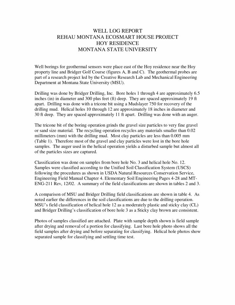
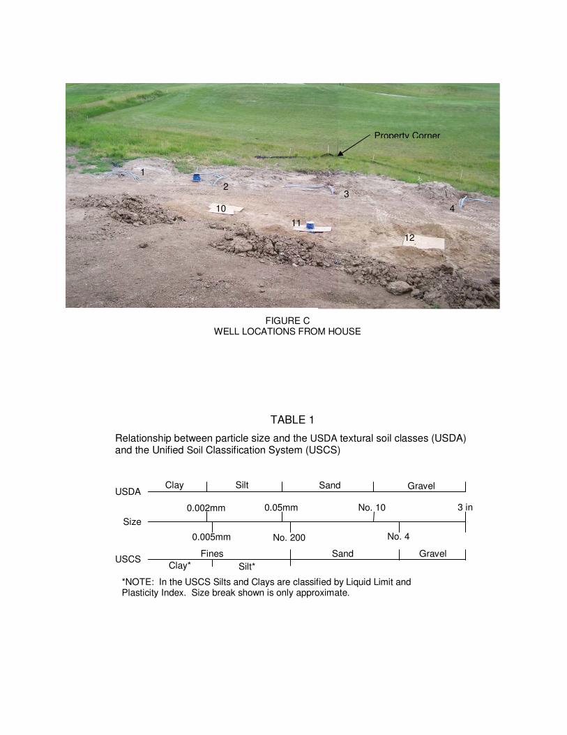
WELL LOG REPORT REHAU MONTANA ECOSMART HOUSE PROJECT HOY RESIDENCE MONTANA STATE UNIVERSITY Well borings for geothermal sensors were place east of the Hoy residence near the Hoy property line and Bridger Golf Course (figures A, B and C). The geothermal probes are part of a research project led by the Creative Research Lab and Mechanical Engineering Department at Montana State University (MSU). Drilling was done by Bridger Drilling, Inc. Bore holes 1 through 4 are approximately 6.5 inches (in) in diameter and 300 plus feet (ft) deep. They are spaced approximately 19 ft apart. Drilling was done with a tricone bit using a Mudslayer 750 for recovery of the drilling mud. Helical holes 10 through 12 are approximately 18 inches in diameter and 30 ft deep. They are spaced approximately 11 ft apart. Drilling was done with an auger. The tricone bit of the boring operation grinds the gravel size particles to very fine gravel or sand size material. The recycling operation recycles any materials smaller than 0.02 millimeters (mm) with the drilling mud. Most clay particles are less than 0.005 mm (Table 1). Therefore most of the gravel and clay particles were lost in the bore hole samples. The auger used in the helical operation yields a disturbed sample but almost all of the particles sizes are captured. Classification was done on samples from bore hole No. 3 and helical hole No. 12. Samples were classified according to the Unified Soil Classification System (USCS) following the procedures as shown in USDA Natural Resources Conservation Service, Engineering Field Manual Chapter 4. Elementary Soil Engineering Pages 4-28 and MT- ENG-211 Rev, 12/02. A summary of the field classifications are shown in tables 2 and 3. A comparison of MSU and Bridger Drilling field classifications are shown in table 4. As noted earlier the differences in the soil classifications are due to the drilling operation. MSU’s field classification of helical hole 12 as a moderately plastic and sticky clay (CL) and Bridger Drilling’s classification of bore hole 3 as a Sticky clay brown are consistent. Photos of samples classified are attached. Plate with sample depth shown is field sample after drying and removal of a portion for classifying. Last bore hole photo shows all the field samples after drying and before separating for classifying. Helical hole photos show separated sample for classifying and settling time test.
-
Upload
truongdieu -
Category
Documents
-
view
216 -
download
0
Transcript of WELL LOG REPORT REHAU MONTANA … LOG REPORT REHAU MONTANA ECOSMART HOUSE PROJECT ... in diameter...
WELL LOG REPORT
REHAU MONTANA ECOSMART HOUSE PROJECT
HOY RESIDENCE
MONTANA STATE UNIVERSITY
Well borings for geothermal sensors were place east of the Hoy residence near the Hoy
property line and Bridger Golf Course (figures A, B and C). The geothermal probes are
part of a research project led by the Creative Research Lab and Mechanical Engineering
Department at Montana State University (MSU).
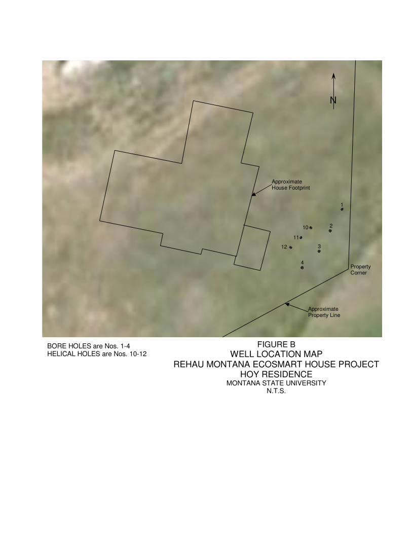
Drilling was done by Bridger Drilling, Inc. Bore holes 1 through 4 are approximately 6.5
inches (in) in diameter and 300 plus feet (ft) deep. They are spaced approximately 19 ft
apart. Drilling was done with a tricone bit using a Mudslayer 750 for recovery of the
drilling mud. Helical holes 10 through 12 are approximately 18 inches in diameter and
30 ft deep. They are spaced approximately 11 ft apart. Drilling was done with an auger.
The tricone bit of the boring operation grinds the gravel size particles to very fine gravel
or sand size material. The recycling operation recycles any materials smaller than 0.02
millimeters (mm) with the drilling mud. Most clay particles are less than 0.005 mm
(Table 1). Therefore most of the gravel and clay particles were lost in the bore hole
samples. The auger used in the helical operation yields a disturbed sample but almost all
of the particles sizes are captured.
Classification was done on samples from bore hole No. 3 and helical hole No. 12.
Samples were classified according to the Unified Soil Classification System (USCS)
following the procedures as shown in USDA Natural Resources Conservation Service,
Engineering Field Manual Chapter 4. Elementary Soil Engineering Pages 4-28 and MT-
ENG-211 Rev, 12/02. A summary of the field classifications are shown in tables 2 and 3.
A comparison of MSU and Bridger Drilling field classifications are shown in table 4. As
noted earlier the differences in the soil classifications are due to the drilling operation.
MSU’s field classification of helical hole 12 as a moderately plastic and sticky clay (CL)
and Bridger Drilling’s classification of bore hole 3 as a Sticky clay brown are consistent.
Photos of samples classified are attached. Plate with sample depth shown is field sample
after drying and removal of a portion for classifying. Last bore hole photo shows all the
field samples after drying and before separating for classifying. Helical hole photos show
separated sample for classifying and settling time test.
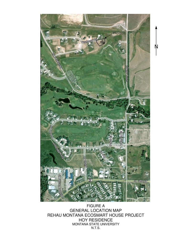
FIGURE A
GENERAL LOCATION MAP REHAU MONTANA ECOSMART HOUSE PROJECT
HOY RESIDENCE MONTANA STATE UNIVERSITY
N.T.S.
N
PROJECT
Approximate Property Line
Property Corner
1
2
3
4
10
11
12
Approximate House Footprint
N
FIGURE B
WELL LOCATION MAP REHAU MONTANA ECOSMART HOUSE PROJECT
HOY RESIDENCE MONTANA STATE UNIVERSITY
N.T.S.
BORE HOLES are Nos. 1-4 HELICAL HOLES are Nos. 10-12
Property Corner
1
3 2
4 10
11
12
FIGURE C WELL LOCATIONS FROM HOUSE
Clay
Clay*
Silt Sand Gravel
Fines
Silt*
Sand Gravel
0.002mm 0.05mm No. 10 3 in
0.005mm No. 200 No. 4
USDA
USCS
Size
*NOTE: In the USCS Silts and Clays are classified by Liquid Limit and Plasticity Index. Size break shown is only approximate.
Relationship between particle size and the USDA textural soil classes (USDA) and the Unified Soil Classification System (USCS)
TABLE 1
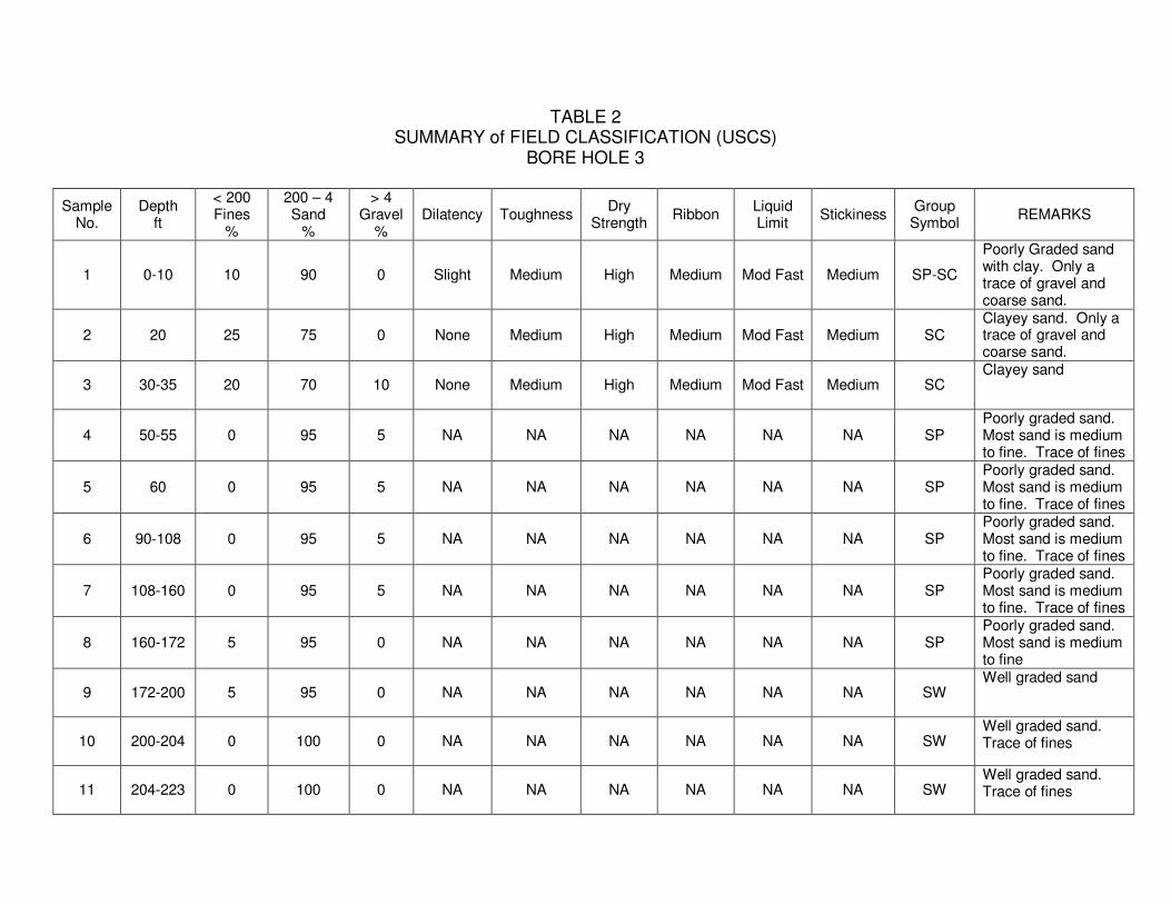
TABLE 2 SUMMARY of FIELD CLASSIFICATION (USCS)
BORE HOLE 3
Sample No.
Depth ft
< 200 Fines
%
200 – 4 Sand
%
> 4 Gravel
% Dilatency Toughness
Dry Strength
Ribbon Liquid Limit
Stickiness Group
Symbol REMARKS
1 0-10 10 90 0 Slight Medium High Medium Mod Fast Medium SP-SC
Poorly Graded sand with clay. Only a trace of gravel and coarse sand.
2 20 25 75 0 None Medium High Medium Mod Fast Medium SC Clayey sand. Only a trace of gravel and coarse sand.
3 30-35 20 70 10 None Medium High Medium Mod Fast Medium SC Clayey sand
4 50-55 0 95 5 NA NA NA NA NA NA SP Poorly graded sand. Most sand is medium to fine. Trace of fines
5 60 0 95 5 NA NA NA NA NA NA SP Poorly graded sand. Most sand is medium to fine. Trace of fines
6 90-108 0 95 5 NA NA NA NA NA NA SP Poorly graded sand. Most sand is medium to fine. Trace of fines
7 108-160 0 95 5 NA NA NA NA NA NA SP Poorly graded sand. Most sand is medium to fine. Trace of fines
8 160-172 5 95 0 NA NA NA NA NA NA SP Poorly graded sand. Most sand is medium to fine
9 172-200 5 95 0 NA NA NA NA NA NA SW Well graded sand
10 200-204 0 100 0 NA NA NA NA NA NA SW Well graded sand. Trace of fines
11 204-223 0 100 0 NA NA NA NA NA NA SW Well graded sand. Trace of fines
Sample No.
Depth ft
< 200 Fines
%
200 – 4 Sand
%
> 4 Gravel
% Dilatency Toughness
Dry Strength
Ribbon Liquid Limit
Stickiness Group
Symbol REMARKS
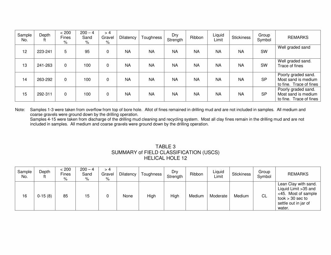
12 223-241 5 95 0 NA NA NA NA NA NA SW Well graded sand
13 241-263 0 100 0 NA NA NA NA NA NA SW Well graded sand. Trace of fines
14 263-292 0 100 0 NA NA NA NA NA NA SP Poorly graded sand. Most sand is medium to fine. Trace of fines
15 292-311 0 100 0 NA NA NA NA NA NA SP Poorly graded sand. Most sand is medium to fine. Trace of fines
Note: Samples 1-3 were taken from overflow from top of bore hole. Allot of fines remained in drilling mud and are not included in samples. All medium and coarse gravels were ground down by the drilling operation. Samples 4-15 were taken from discharge of the drilling mud cleaning and recycling system. Most all clay fines remain in the drilling mud and are not included in samples. All medium and coarse gravels were ground down by the drilling operation.
TABLE 3 SUMMARY of FIELD CLASSIFICATION (USCS)
HELICAL HOLE 12
Sample No.
Depth ft
< 200 Fines
%
200 – 4 Sand
%
> 4 Gravel
% Dilatency Toughness
Dry Strength
Ribbon Liquid Limit
Stickiness Group
Symbol REMARKS
16 0-15 (8) 85 15 0 None High High Medium Moderate Medium CL
Lean Clay with sand. Liquid Limit >35 and <45. Most of sample took > 30 sec to settle out in jar of water.
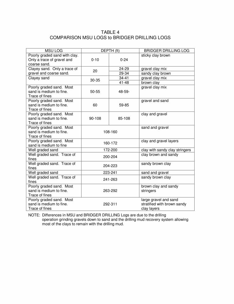
TABLE 4 COMPARISON MSU LOGS to BRIDGER DRILLING LOGS
MSU LOG DEPTH (ft) BRIDGER DRILLING LOG Poorly graded sand with clay. Only a trace of gravel and coarse sand.
0-10 0-24 sticky clay brown
24-29 gravel clay mix Clayey sand. Only a trace of gravel and coarse sand.
20 29-34 sandy clay brown 34-41 gravel clay mix Clayey sand
30-35 41-48 brown clay
Poorly graded sand. Most sand is medium to fine. Trace of fines
50-55 48-59- gravel clay mix
Poorly graded sand. Most sand is medium to fine. Trace of fines
60 59-85 gravel and sand
Poorly graded sand. Most sand is medium to fine. Trace of fines
90-108 85-108 clay and gravel
Poorly graded sand. Most sand is medium to fine. Trace of fines
108-160 sand and gravel
Poorly graded sand. Most sand is medium to fine
160-172 clay and gravel layers
Well graded sand 172-200 clay with sandy clay stringers Well graded sand. Trace of fines
200-204 clay brown and sandy
Well graded sand. Trace of fines
204-223 sandy brown clay
Well graded sand 223-241 sand and gravel Well graded sand. Trace of fines
241-263 sandy brown clay
Poorly graded sand. Most sand is medium to fine. Trace of fines
263-292 brown clay and sandy stringers
Poorly graded sand. Most sand is medium to fine. Trace of fines
292-311 large gravel and sand stratified with brown sandy clay layers
NOTE: Differences in MSU and BRIDGER DRILLING Logs are due to the drilling operation grinding gravels down to sand and the drilling mud recovery system allowing most of the clays to remain with the drilling mud.

Sample #1 0-10 feet Sample #2 20 feet
Sample #4 50-55 feetSample #3 30-35 feet
Sample #5 90-108 feet Sample #6 60 feet
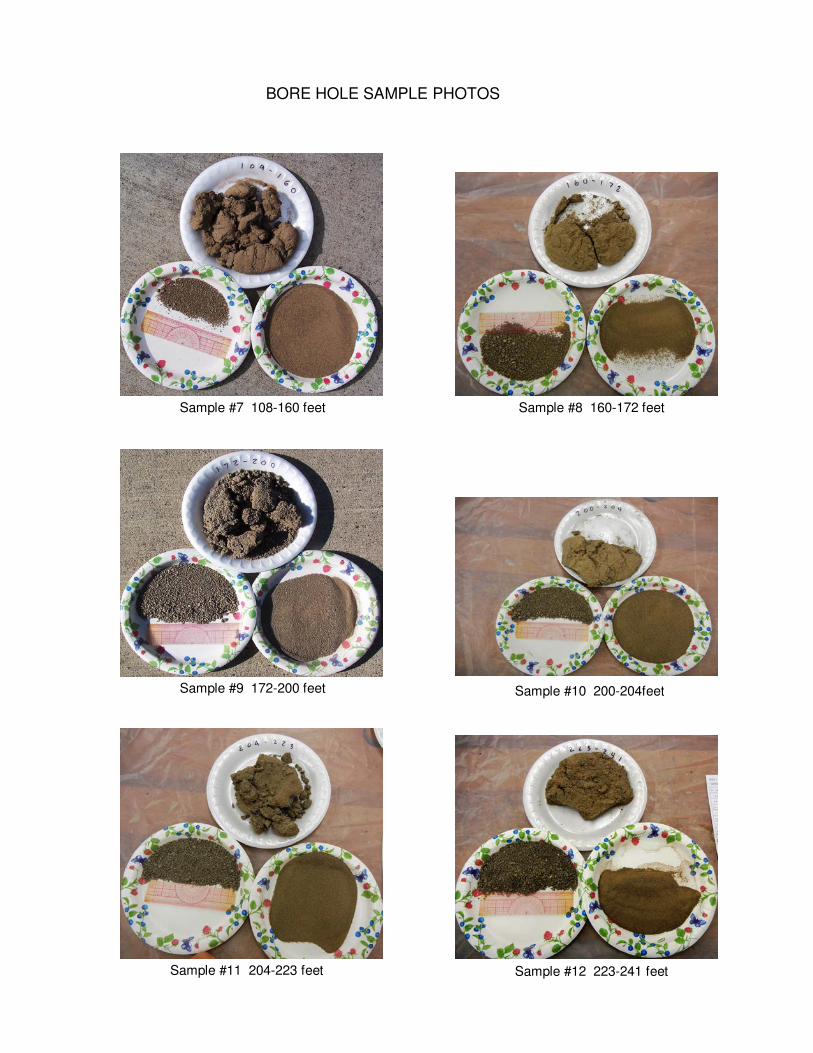
BORE HOLE SAMPLE PHOTOS
BORE HOLE SAMPLE PHOTOS
Sample #7 108-160 feet Sample #8 160-172 feet
Sample #11 204-223 feet Sample #12 223-241 feet
Sample #9 172-200 feet Sample #10 200-204feet
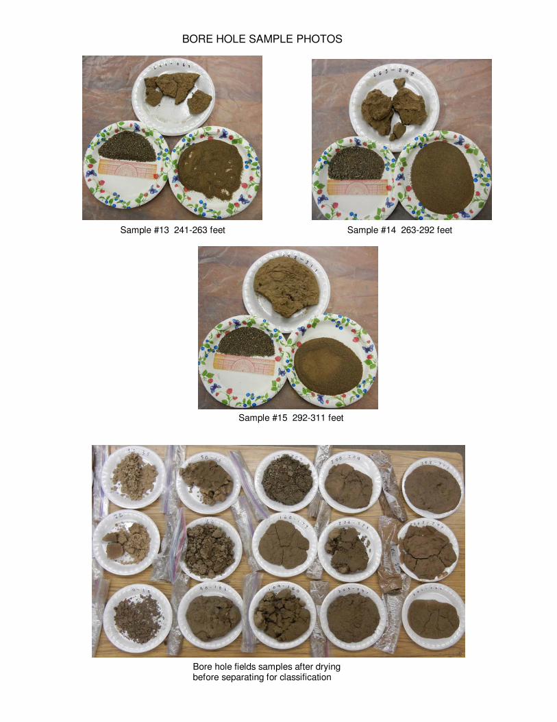
BORE HOLE SAMPLE PHOTOS
Sample #13 241-263 feet Sample #14 263-292 feet
Sample #15 292-311 feet
Bore hole fields samples after drying before separating for classification
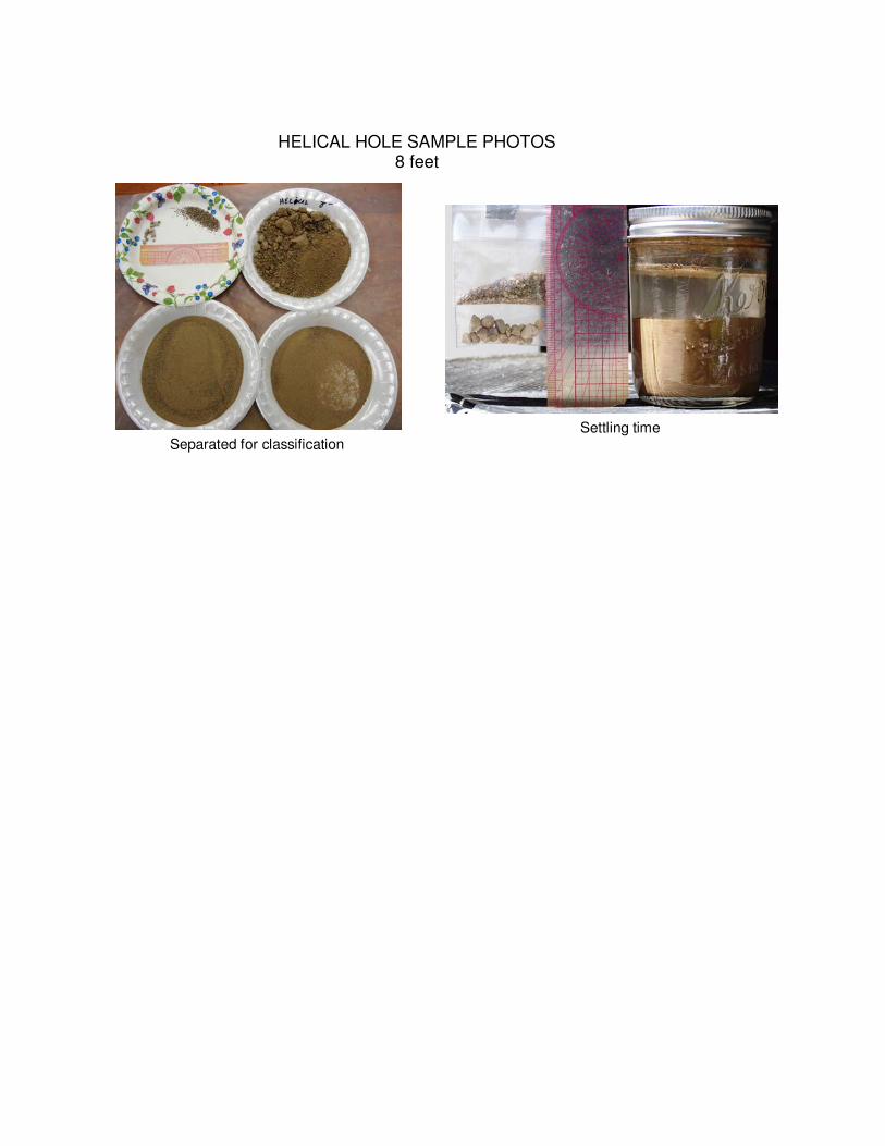
HELICAL HOLE SAMPLE PHOTOS 8 feet
Separated for classification
Settling time