Weldment Design and Simplifications - enghouse.com.au Design and Simplifications.pdf · Weldment...
9
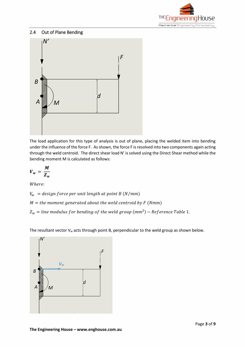
Page 1 of 9 The Engineering House – www.enghouse.com.au Weldment Design and Simplifications 1 Introduction - The Line Method The sizing of weld beads is a well documented engineering calculation and it is quite easy to find many references. My favourite method for sizing welds is one called the line method. This method calculates the geometric properties of a weld group by first representing it as a series of zero thickness lines. A force per unit length requirement is then calculated for each critical weld location and from this a weld size can be chosen to suit. There is no need for trial weld geometries or iterations. The line method is a conservative approach in that it does not account for the changes in the weld group’s geometry as the throat thickness of the weld increases beyond that of a line. Because of this, the approach becomes more and more conservative as the throat thickness of a weld bead is increased. For quick design calculations though where the strength of a weld group need not be determined to such a fine detail (almost all calculations will fit into this category), this method works perfectly. 2 Weld Group Geometry The line method represents each weld in a group as a line of zero thickness. The positioning of this line representation should always be at the root of the welded joint no matter what type of weld is used. Intermittent welds should be first calculated as continuous and later sized based on their intermittency. I.e. if a 1m joint requires 200N/mm of weld strength, a 75-150mm weld stagger will equate to a 0.5m effective joint requiring: 1 0.5 × 200 = 400 ℎ ⁄ ⁄ 2.1 Types of Weld Group Formulae Below are a number of weld group formulae intended to help quantify the stresses found within a weld group. Many weld applications can have their stresses broken down into constituent components capable of being solved using these formulae. The results of these formulae can be later combined to provide an overall analysis of almost any weld. 2.2 Axial or Direct Shear In this instance the weld or weld group is loaded either axially or in shear. There are no torsional or moment affects acting upon the weld group. = ′ () = ′ ( ) ℎ: = ℎ ℎ ( ) ⁄ ′ ′ = ℎ () = ℎ ℎ () The resultant vector Vw is orientated in the direction of the design force F’ or N’. F’ N’
Transcript of Weldment Design and Simplifications - enghouse.com.au Design and Simplifications.pdf · Weldment...

Page 1 of 9 The Engineering House – www.enghouse.com.au
Weldment Design and Simplifications
1 Introduction - The Line Method
The sizing of weld beads is a well documented engineering calculation and it is quite easy to find many
references. My favourite method for sizing welds is one called the line method. This method
calculates the geometric properties of a weld group by first representing it as a series of zero thickness
lines. A force per unit length requirement is then calculated for each critical weld location and from
this a weld size can be chosen to suit. There is no need for trial weld geometries or iterations.
The line method is a conservative approach in that it does not account for the changes in the weld
group’s geometry as the throat thickness of the weld increases beyond that of a line. Because of this,
the approach becomes more and more conservative as the throat thickness of a weld bead is
increased. For quick design calculations though where the strength of a weld group need not be
determined to such a fine detail (almost all calculations will fit into this category), this method works
perfectly.
2 Weld Group Geometry
The line method represents each weld in a group as a line of zero thickness. The positioning of this
line representation should always be at the root of the welded joint no matter what type of weld is
used.
Intermittent welds should be first calculated as continuous and later sized based on their
intermittency. I.e. if a 1m joint requires 200N/mm of weld strength, a 75-150mm weld stagger will
equate to a 0.5m effective joint requiring:
1𝑚
0.5𝑚× 200 𝑁 𝑚𝑚 = 400 𝑁 𝑚𝑚 𝑜𝑓 𝑤𝑒𝑙𝑑 𝑠𝑡𝑟𝑒𝑛𝑔𝑡ℎ⁄⁄
2.1 Types of Weld Group Formulae
Below are a number of weld group formulae intended to help quantify the stresses found within a
weld group. Many weld applications can have their stresses broken down into constituent
components capable of being solved using these formulae. The results of these formulae can be later
combined to provide an overall analysis of almost any weld.
2.2 Axial or Direct Shear
In this instance the weld or weld group is loaded either axially or in shear. There are no torsional or moment affects acting upon the weld group.
𝑽𝒘 = 𝑭′
𝒍 (𝒂𝒙𝒊𝒂𝒍) 𝒐𝒓 𝑽𝒘 =
𝑵′
𝒍 (𝒊𝒏 𝒔𝒉𝒆𝒂𝒓)
𝑊ℎ𝑒𝑟𝑒:
𝑉𝑤 = 𝑡ℎ𝑒 𝑑𝑒𝑠𝑖𝑔𝑛 𝑓𝑜𝑟𝑐𝑒 𝑝𝑒𝑟 𝑢𝑛𝑖𝑡 𝑙𝑒𝑛𝑔𝑡ℎ 𝑜𝑓 𝑤𝑒𝑙𝑑 (𝑁 𝑚𝑚)⁄ 𝑁′𝑜𝑟 𝐹′ = 𝑡ℎ𝑒 𝑑𝑒𝑠𝑖𝑔𝑛 𝑓𝑜𝑟𝑐𝑒 (𝑁) 𝑙 = 𝑡ℎ𝑒 𝑡𝑜𝑡𝑎𝑙 𝑤𝑒𝑙𝑑 𝑙𝑒𝑛𝑔𝑡ℎ (𝑚𝑚) The resultant vector Vw is orientated in the direction of the design force F’ or N’.
F’
N’
Page 2 of 9 The Engineering House – www.enghouse.com.au
2.3 In-Plane Torsion
In this instance a weld group is loaded in plane and under torsion by the force F. This force is resolved
into two components: N’ and M acting through the weld group’s centroid. N’ is solved using the Direct
Shear method while M is solved using the equation below:
𝑽𝒘 = 𝑴 × 𝒚
𝑱𝒘
𝑊ℎ𝑒𝑟𝑒:
𝑉𝑤 = 𝑡ℎ𝑒 𝑚𝑎𝑥𝑖𝑚𝑢𝑚 𝑑𝑒𝑠𝑖𝑔𝑛 𝑓𝑜𝑟𝑐𝑒 𝑝𝑒𝑟 𝑢𝑛𝑖𝑡 𝑙𝑒𝑛𝑔𝑡ℎ 𝑜𝑓 𝑡ℎ𝑒 𝑤𝑒𝑙𝑑, 𝑙𝑜𝑐𝑎𝑡𝑒𝑑 𝑎𝑡 𝑝𝑜𝑖𝑛𝑡 𝐴 (𝑁 𝑚𝑚)⁄
𝑀 = 𝑡ℎ𝑒 𝑚𝑜𝑚𝑒𝑛𝑡 𝑔𝑒𝑛𝑒𝑟𝑎𝑡𝑒𝑑 𝑏𝑦 𝐹 𝑎𝑏𝑜𝑢𝑡 𝑡ℎ𝑒 𝑤𝑒𝑙𝑑 𝑐𝑒𝑛𝑡𝑟𝑜𝑖𝑑 (𝑁𝑚𝑚)
𝑦 = 𝑡ℎ𝑒 𝑑𝑖𝑠𝑡𝑎𝑛𝑐𝑒 𝑓𝑟𝑜𝑚 𝑡ℎ𝑒 𝑐𝑒𝑛𝑡𝑟𝑜𝑖𝑑 𝑜𝑓 𝑡ℎ𝑒 𝑤𝑒𝑙𝑑 𝑔𝑟𝑜𝑢𝑝 𝑡𝑜 𝑝𝑜𝑖𝑛𝑡 𝐴 (𝑚𝑚)
𝐽𝑤 = 𝑝𝑜𝑙𝑎𝑟 𝑙𝑖𝑛𝑒 𝑚𝑜𝑚𝑒𝑛𝑡 𝑜𝑓 𝑖𝑛𝑒𝑟𝑡𝑖𝑎 𝑜𝑓 𝑡ℎ𝑒 𝑤𝑒𝑙𝑑 𝑔𝑟𝑜𝑢𝑝 (𝑚𝑚3) − 𝑅𝑒𝑓𝑒𝑟𝑒𝑛𝑐𝑒 𝑇𝑎𝑏𝑙𝑒 1.
The resultant vector Vw is located at point A and orientated perpendicular to the dimension y. The
vector acts in the direction of the moment M as shown.
F
y
N’
M
F
y
N’
M Vw
A
Page 3 of 9 The Engineering House – www.enghouse.com.au
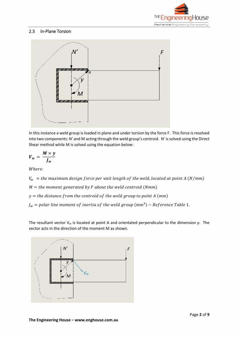
2.4 Out of Plane Bending
The load application for this type of analysis is out of plane, placing the welded item into bending
under the influence of the force F. As shown, the force F is resolved into two components again acting
through the weld centroid. The direct shear load N’ is solved using the Direct Shear method while the
bending moment M is calculated as follows:
𝑽𝒘 = 𝑴
𝒁𝒘
𝑊ℎ𝑒𝑟𝑒:
𝑉𝑤 = 𝑑𝑒𝑠𝑖𝑔𝑛 𝑓𝑜𝑟𝑐𝑒 𝑝𝑒𝑟 𝑢𝑛𝑖𝑡 𝑙𝑒𝑛𝑔𝑡ℎ 𝑎𝑡 𝑝𝑜𝑖𝑛𝑡 𝐵 (𝑁 𝑚𝑚⁄ )
𝑀 = 𝑡ℎ𝑒 𝑚𝑜𝑚𝑒𝑛𝑡 𝑔𝑒𝑛𝑒𝑟𝑎𝑡𝑒𝑑 𝑎𝑏𝑜𝑢𝑡 𝑡ℎ𝑒 𝑤𝑒𝑙𝑑 𝑐𝑒𝑛𝑡𝑟𝑜𝑖𝑑 𝑏𝑦 𝐹 (𝑁𝑚𝑚)
𝑍𝑤 = 𝑙𝑖𝑛𝑒 𝑚𝑜𝑑𝑢𝑙𝑢𝑠 𝑓𝑜𝑟 𝑏𝑒𝑛𝑑𝑖𝑛𝑔 𝑜𝑓 𝑡ℎ𝑒 𝑤𝑒𝑙𝑑 𝑔𝑟𝑜𝑢𝑝 (𝑚𝑚2) − 𝑅𝑒𝑓𝑒𝑟𝑒𝑛𝑐𝑒 𝑇𝑎𝑏𝑙𝑒 1.
The resultant vector Vw acts through point B, perpendicular to the weld group as shown below.
N’
F
d A M
B
Vw
Page 4 of 9 The Engineering House – www.enghouse.com.au
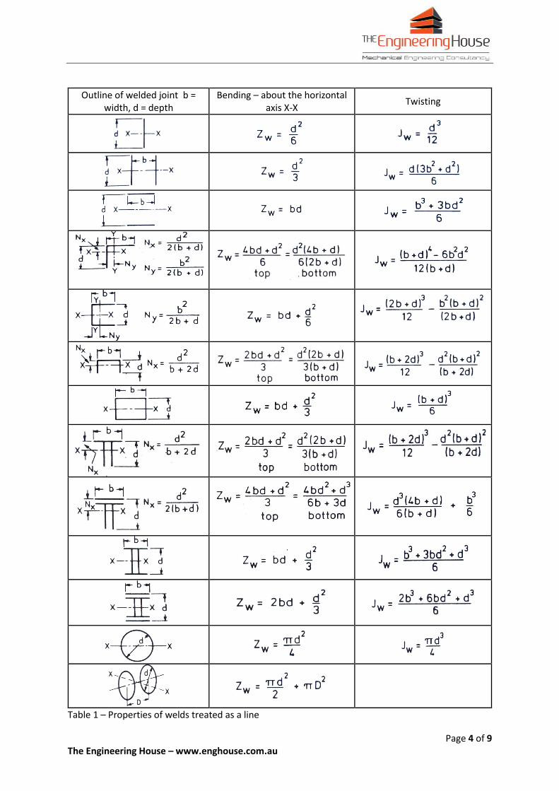
Outline of welded joint b = width, d = depth
Bending – about the horizontal axis X-X
Twisting
Table 1 – Properties of welds treated as a line
Page 5 of 9 The Engineering House – www.enghouse.com.au
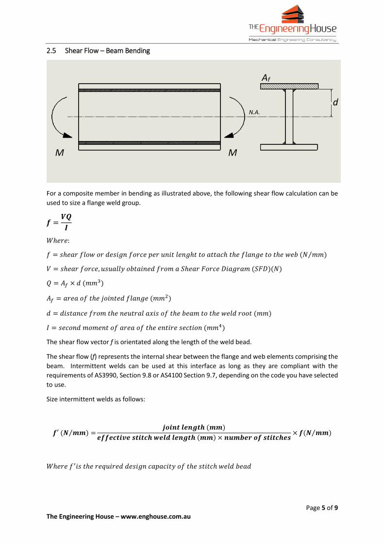
2.5 Shear Flow – Beam Bending
For a composite member in bending as illustrated above, the following shear flow calculation can be
used to size a flange weld group.
𝒇 =𝑽𝑸
𝑰
𝑊ℎ𝑒𝑟𝑒:
𝑓 = 𝑠ℎ𝑒𝑎𝑟 𝑓𝑙𝑜𝑤 𝑜𝑟 𝑑𝑒𝑠𝑖𝑔𝑛 𝑓𝑜𝑟𝑐𝑒 𝑝𝑒𝑟 𝑢𝑛𝑖𝑡 𝑙𝑒𝑛𝑔ℎ𝑡 𝑡𝑜 𝑎𝑡𝑡𝑎𝑐ℎ 𝑡ℎ𝑒 𝑓𝑙𝑎𝑛𝑔𝑒 𝑡𝑜 𝑡ℎ𝑒 𝑤𝑒𝑏 (𝑁 𝑚𝑚⁄ )
𝑉 = 𝑠ℎ𝑒𝑎𝑟 𝑓𝑜𝑟𝑐𝑒, 𝑢𝑠𝑢𝑎𝑙𝑙𝑦 𝑜𝑏𝑡𝑎𝑖𝑛𝑒𝑑 𝑓𝑟𝑜𝑚 𝑎 𝑆ℎ𝑒𝑎𝑟 𝐹𝑜𝑟𝑐𝑒 𝐷𝑖𝑎𝑔𝑟𝑎𝑚 (𝑆𝐹𝐷)(𝑁)
𝑄 = 𝐴𝑓 × 𝑑 (𝑚𝑚3)
𝐴𝑓 = 𝑎𝑟𝑒𝑎 𝑜𝑓 𝑡ℎ𝑒 𝑗𝑜𝑖𝑛𝑡𝑒𝑑 𝑓𝑙𝑎𝑛𝑔𝑒 (𝑚𝑚2)
𝑑 = 𝑑𝑖𝑠𝑡𝑎𝑛𝑐𝑒 𝑓𝑟𝑜𝑚 𝑡ℎ𝑒 𝑛𝑒𝑢𝑡𝑟𝑎𝑙 𝑎𝑥𝑖𝑠 𝑜𝑓 𝑡ℎ𝑒 𝑏𝑒𝑎𝑚 𝑡𝑜 𝑡ℎ𝑒 𝑤𝑒𝑙𝑑 𝑟𝑜𝑜𝑡 (𝑚𝑚)
𝐼 = 𝑠𝑒𝑐𝑜𝑛𝑑 𝑚𝑜𝑚𝑒𝑛𝑡 𝑜𝑓 𝑎𝑟𝑒𝑎 𝑜𝑓 𝑡ℎ𝑒 𝑒𝑛𝑡𝑖𝑟𝑒 𝑠𝑒𝑐𝑡𝑖𝑜𝑛 (𝑚𝑚4)
The shear flow vector f is orientated along the length of the weld bead.
The shear flow (f) represents the internal shear between the flange and web elements comprising the
beam. Intermittent welds can be used at this interface as long as they are compliant with the
requirements of AS3990, Section 9.8 or AS4100 Section 9.7, depending on the code you have selected
to use.
Size intermittent welds as follows:
𝒇′ (𝑵 𝒎𝒎) =⁄𝒋𝒐𝒊𝒏𝒕 𝒍𝒆𝒏𝒈𝒕𝒉 (𝒎𝒎)
𝒆𝒇𝒇𝒆𝒄𝒕𝒊𝒗𝒆 𝒔𝒕𝒊𝒕𝒄𝒉 𝒘𝒆𝒍𝒅 𝒍𝒆𝒏𝒈𝒕𝒉 (𝒎𝒎) × 𝒏𝒖𝒎𝒃𝒆𝒓 𝒐𝒇 𝒔𝒕𝒊𝒕𝒄𝒉𝒆𝒔× 𝒇(𝑵 𝒎𝒎)⁄
𝑊ℎ𝑒𝑟𝑒 𝑓′𝑖𝑠 𝑡ℎ𝑒 𝑟𝑒𝑞𝑢𝑖𝑟𝑒𝑑 𝑑𝑒𝑠𝑖𝑔𝑛 𝑐𝑎𝑝𝑎𝑐𝑖𝑡𝑦 𝑜𝑓 𝑡ℎ𝑒 𝑠𝑡𝑖𝑡𝑐ℎ 𝑤𝑒𝑙𝑑 𝑏𝑒𝑎𝑑
M M
d
Af
N.A.
Page 6 of 9 The Engineering House – www.enghouse.com.au
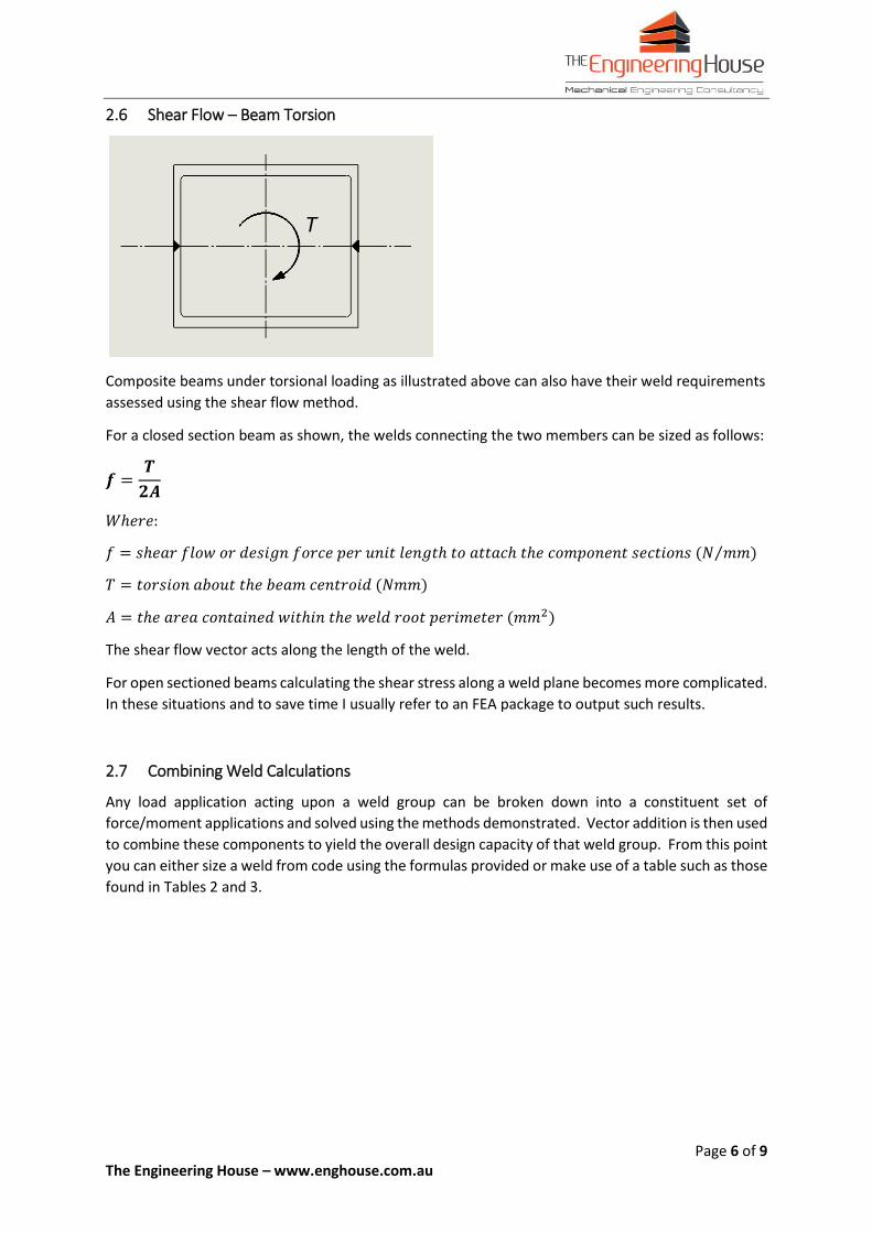
2.6 Shear Flow – Beam Torsion
Composite beams under torsional loading as illustrated above can also have their weld requirements
assessed using the shear flow method.
For a closed section beam as shown, the welds connecting the two members can be sized as follows:
𝒇 =𝑻
𝟐𝑨
𝑊ℎ𝑒𝑟𝑒:
𝑓 = 𝑠ℎ𝑒𝑎𝑟 𝑓𝑙𝑜𝑤 𝑜𝑟 𝑑𝑒𝑠𝑖𝑔𝑛 𝑓𝑜𝑟𝑐𝑒 𝑝𝑒𝑟 𝑢𝑛𝑖𝑡 𝑙𝑒𝑛𝑔𝑡ℎ 𝑡𝑜 𝑎𝑡𝑡𝑎𝑐ℎ 𝑡ℎ𝑒 𝑐𝑜𝑚𝑝𝑜𝑛𝑒𝑛𝑡 𝑠𝑒𝑐𝑡𝑖𝑜𝑛𝑠 (𝑁 𝑚𝑚)⁄
𝑇 = 𝑡𝑜𝑟𝑠𝑖𝑜𝑛 𝑎𝑏𝑜𝑢𝑡 𝑡ℎ𝑒 𝑏𝑒𝑎𝑚 𝑐𝑒𝑛𝑡𝑟𝑜𝑖𝑑 (𝑁𝑚𝑚)
𝐴 = 𝑡ℎ𝑒 𝑎𝑟𝑒𝑎 𝑐𝑜𝑛𝑡𝑎𝑖𝑛𝑒𝑑 𝑤𝑖𝑡ℎ𝑖𝑛 𝑡ℎ𝑒 𝑤𝑒𝑙𝑑 𝑟𝑜𝑜𝑡 𝑝𝑒𝑟𝑖𝑚𝑒𝑡𝑒𝑟 (𝑚𝑚2)
The shear flow vector acts along the length of the weld.
For open sectioned beams calculating the shear stress along a weld plane becomes more complicated.
In these situations and to save time I usually refer to an FEA package to output such results.
2.7 Combining Weld Calculations
Any load application acting upon a weld group can be broken down into a constituent set of
force/moment applications and solved using the methods demonstrated. Vector addition is then used
to combine these components to yield the overall design capacity of that weld group. From this point
you can either size a weld from code using the formulas provided or make use of a table such as those
found in Tables 2 and 3.
T
Page 7 of 9 The Engineering House – www.enghouse.com.au
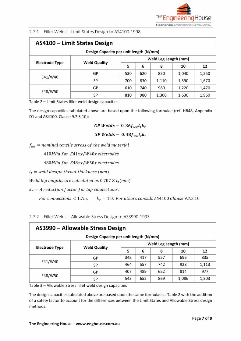
2.7.1 Fillet Welds – Limit States Design to AS4100-1998
AS4100 – Limit States Design
Design Capacity per unit length (N/mm)
Electrode Type Weld Quality Weld Leg Length (mm)
5 6 8 10 12
E41/W40 GP 530 620 830 1,040 1,250
SP 700 830 1,110 1,390 1,670
E48/W50 GP 610 740 980 1,220 1,470
SP 810 980 1,300 1,630 1,960
Table 2 – Limit States fillet weld design capacities
The design capacities tabulated above are based upon the following formulae (ref. HB48, Appendix
D1 and AS4100, Clause 9.7.3.10):
𝑮𝑷 𝑾𝒆𝒍𝒅𝒔 − 𝟎. 𝟑𝟔𝒇𝒖𝒘𝒕𝒕𝒌𝒓
𝑺𝑷 𝑾𝒆𝒍𝒅𝒔 − 𝟎. 𝟒𝟖𝒇𝒖𝒘𝒕𝒕𝒌𝒓
𝑓𝑢𝑤 = 𝑛𝑜𝑚𝑖𝑛𝑎𝑙 𝑡𝑒𝑛𝑠𝑖𝑙𝑒 𝑠𝑡𝑟𝑒𝑠𝑠 𝑜𝑓 𝑡ℎ𝑒 𝑤𝑒𝑙𝑑 𝑚𝑎𝑡𝑒𝑟𝑖𝑎𝑙
410𝑀𝑃𝑎 𝑓𝑜𝑟 𝐸41𝑥𝑥 𝑊40𝑥 𝑒𝑙𝑒𝑐𝑡𝑟𝑜𝑑𝑒𝑠⁄
480𝑀𝑃𝑎 𝑓𝑜𝑟 𝐸48𝑥𝑥 𝑊50𝑥 𝑒𝑙𝑒𝑐𝑡𝑟𝑜𝑑𝑒𝑠⁄
𝑡𝑡 = 𝑤𝑒𝑙𝑑 𝑑𝑒𝑠𝑖𝑔𝑛 𝑡ℎ𝑟𝑜𝑎𝑡 𝑡ℎ𝑖𝑐𝑘𝑛𝑒𝑠𝑠 (𝑚𝑚)
𝑊𝑒𝑙𝑑 𝑙𝑒𝑔 𝑙𝑒𝑛𝑔𝑡ℎ𝑠 𝑎𝑟𝑒 𝑐𝑎𝑙𝑐𝑢𝑙𝑎𝑡𝑒𝑑 𝑎𝑠 0.707 × 𝑡𝑡(𝑚𝑚)
𝑘𝑟 = 𝐴 𝑟𝑒𝑑𝑢𝑐𝑡𝑖𝑜𝑛 𝑓𝑎𝑐𝑡𝑜𝑟 𝑓𝑜𝑟 𝑙𝑎𝑝 𝑐𝑜𝑛𝑛𝑒𝑐𝑡𝑖𝑜𝑛𝑠.
𝐹𝑜𝑟 𝑐𝑜𝑛𝑛𝑒𝑐𝑡𝑖𝑜𝑛𝑠 < 1.7𝑚, 𝑘𝑟 = 1.0. 𝐹𝑜𝑟 𝑜𝑡ℎ𝑒𝑟𝑠 𝑐𝑜𝑛𝑠𝑢𝑙𝑡 𝐴𝑆4100 𝐶𝑙𝑎𝑢𝑠𝑒 9.7.3.10
2.7.2 Fillet Welds – Allowable Stress Design to AS3990-1993
AS3990 – Allowable Stress Design
Design Capacity per unit length (N/mm)
Electrode Type Weld Quality Weld Leg Length (mm)
5 6 8 10 12
E41/W40 GP 348 417 557 696 835
SP 464 557 742 928 1,113
E48/W50 GP 407 489 652 814 977
SP 543 652 869 1,086 1,303
Table 3 – Allowable Stress fillet weld design capacities
The design capacities tabulated above are based upon the same formulae as Table 2 with the addition
of a safety factor to account for the differences between the Limit States and Allowable Stress design
methods.
Page 8 of 9 The Engineering House – www.enghouse.com.au
To equate the Limit States method with the Allowable Stress method in this instance, a load factor of
0.67 is introduced.
Since the Limit States method uses two forms of design factor, a Load and a Capacity Factor, this had
to be related to the Allowable Stress method which employs only a Capacity Factor. The Limit States
weld size calculation from Table 2 takes into account only the Capacity Factor, so the two methods
were equated as follows:
𝐴𝑙𝑙𝑜𝑤𝑎𝑏𝑙𝑒 𝑆𝑡𝑟𝑒𝑠𝑠 𝑊𝑒𝑙𝑑 𝑆𝑖𝑧𝑒 =𝐿𝑖𝑚𝑖𝑡 𝑆𝑡𝑎𝑡𝑒𝑠 𝑊𝑒𝑙𝑑 𝑆𝑖𝑧𝑒
𝐿𝑜𝑎𝑑 𝐹𝑎𝑐𝑡𝑜𝑟
AS4100 derives its Load Factors predominantly from AS1170.0. The largest of these factors and often
the most used is 1.5. Hence the Load Factor applied to the Limit State Weld Size result is:
𝐴𝑙𝑙𝑜𝑤𝑎𝑏𝑙𝑒 𝑆𝑡𝑟𝑒𝑠𝑠 𝑊𝑒𝑙𝑑 𝑆𝑖𝑧𝑒 =𝐿𝑖𝑚𝑖𝑡 𝑆𝑡𝑎𝑡𝑒𝑠 𝑊𝑒𝑙𝑑 𝑆𝑖𝑧𝑒
1.5= 0.67 × 𝐿𝑖𝑚𝑖𝑡 𝑆𝑡𝑎𝑡𝑒𝑠 𝑊𝑒𝑙𝑑 𝑆𝑖𝑧𝑒
Note this is a conservative approach but provides a much more workable solution to the method
employed by AS3990-1993.
2.7.3 Butt Welds – Limit States Design to AS4100-1998
Note that in accordance with AS4100 Section 9.7.2, no analysis is required for category SP complete
penetration butt welds. The design capacity of the joint is equal to the weaker component being
jointed. For category GP butt welds a 2/3 Capacity Factor should to be introduced.
Incomplete penetration butt welds can be assessed in the same manner as for fillet welds provided
the design throat thickness used is in accordance with AS1554.1 Table E2.
2.7.4 Butt Welds – Allowable Stress Design to AS3990-1993
Note that in accordance with AS3990 Section 9.8.2(a), no analysis is required for complete penetration
butt welds. The design capacity of the joint is equal to the weaker component being jointed.
Incomplete penetration butt welds can be assessed in the same manner as for fillet welds provided
the design throat thickness used is in accordance with AS1554.1 Table E2 and a Reduction Factor of
0.5 is applied to the ultimate strength of the weld material. This is a more conservative approach to
that stipulated by the Limit States method.
Page 9 of 9 The Engineering House – www.enghouse.com.au
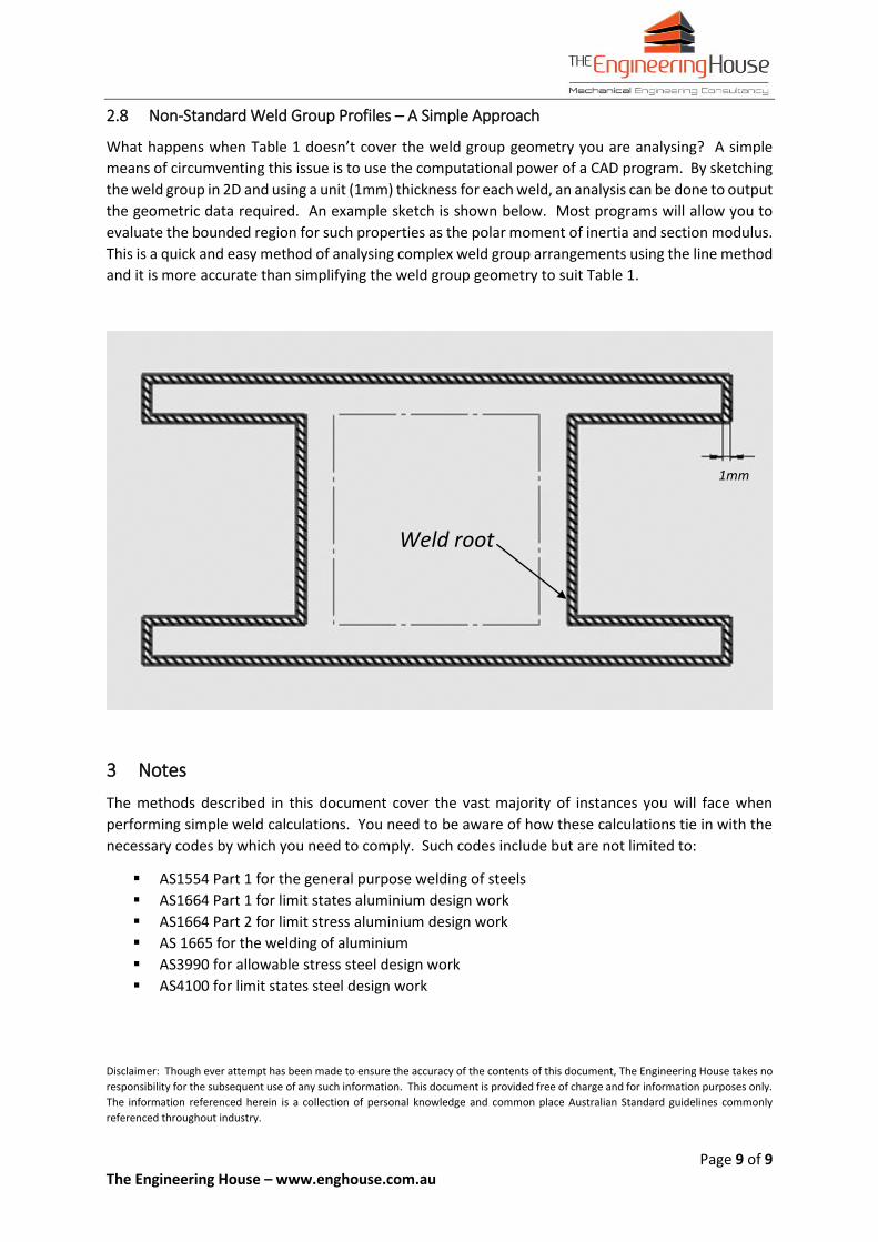
2.8 Non-Standard Weld Group Profiles – A Simple Approach
What happens when Table 1 doesn’t cover the weld group geometry you are analysing? A simple
means of circumventing this issue is to use the computational power of a CAD program. By sketching
the weld group in 2D and using a unit (1mm) thickness for each weld, an analysis can be done to output
the geometric data required. An example sketch is shown below. Most programs will allow you to
evaluate the bounded region for such properties as the polar moment of inertia and section modulus.
This is a quick and easy method of analysing complex weld group arrangements using the line method
and it is more accurate than simplifying the weld group geometry to suit Table 1.
3 Notes
The methods described in this document cover the vast majority of instances you will face when
performing simple weld calculations. You need to be aware of how these calculations tie in with the
necessary codes by which you need to comply. Such codes include but are not limited to:
AS1554 Part 1 for the general purpose welding of steels
AS1664 Part 1 for limit states aluminium design work
AS1664 Part 2 for limit stress aluminium design work
AS 1665 for the welding of aluminium
AS3990 for allowable stress steel design work
AS4100 for limit states steel design work
Disclaimer: Though ever attempt has been made to ensure the accuracy of the contents of this document, The Engineering House takes no
responsibility for the subsequent use of any such information. This document is provided free of charge and for information purposes only.
The information referenced herein is a collection of personal knowledge and common place Australian Standard guidelines commonly
referenced throughout industry.
1mm
Weld root