
WELDING INDUSTRIES OF · model no. cp33-02, rev. f 11/00 l quality welding products, systems and...
14
WELDING INDUSTRIES OF AUSTRALIA A DIVISION OF WELDING INDUSTRIES LTD ABN 18 004 547 111 Head Office and International Sales 5 Allan Street, Melrose Park South Australia, 5039 Telephone (08) 8276 6494 Facsimile (08) 8276 6327 www.weldingindustries.com.au [email protected] OWNERS MANUAL WELDMATIC FABRICATOR MODEL NO. CP33-02, REV. F 11/00 l QUALITY WELDING PRODUCTS, SYSTEMS AND SERVICE 4 f: 7 i M I-
Transcript of WELDING INDUSTRIES OF · model no. cp33-02, rev. f 11/00 l quality welding products, systems and...

WELDING INDUSTRIES OF AUSTRALIA A DIVISION OF WELDING INDUSTRIES LTD
ABN 18 004 547 111
Head Office and International Sales
5 Allan Street, Melrose Park
South Australia, 5039
Telephone (08) 8276 6494 Facsimile (08) 8276 6327
www.weldingindustries.com.au
OWNERS MANUAL
WELDMATIC FABRICATOR
MODEL NO. CP33-02, REV. F
11/00
l
QUALITY WELDING PRODUCTS, SYSTEMS AND SERVICE 4 f: 7 i M
I -

Page 2 WELDMATIC FABRICATOR MANUAL
SAFETY Before this equipment is put into operation, the safety practices section at the back of
the manual must be read completely. This will help to avoid possible injury due to misuse or improper welding applications.
INTRODUCTION Gas Metal Arc Welding (G.M.A.) is a basically simple welding process, where a
consumable wire is fed by motor driven drive rollers to a welding gun, and where welding current is supplied from the welding power source. The welding arc is struck between the work piece and the end of the wire, which melts into the weld pool. The arc and the weld pool are both shielded by gas flow from the gun, or in the case of ”self shielded” wires, by gases generated by the wire core.
The process is very versatile in that by selection of the correct wire composition, diameter and shielding gas, it can be used for applications ranging from sheetmetal to heavy plate, and metals ranging from carbon steel to aluminium alloys.
HANDLING Prior to installing this equipment, clean ali packing material from around the unit and
carefully inspect for any damage that may have occurred in shipment must be filed by the purchaser with Welding Industries of Australia, or authorised agent immediately. (Refer to Equipment Warranty Card enclosed with this Operating Manual). When requesting information concerning this equipment, it is essential to supply correct Model Identification and Machine serial number.
CONTENTS PAGE
Sec.? ................... Specifications ................................................. 3 Sec.2 ................... Installation ...................................................... 4 Sec3 ................... Set up for Welding ......................................... 7 Sec.4 ................... Safety Devices ............................................... 9 Sec5 ................... Maintenance .................................................. 9 Sec.6 ................... Parts List. ....................................................... I O Sec.7 ................... Safe Practices ................................................ 13
i FIGURES PAGE
Fig 1 .................... Fitting Mobile Kit ............................................ 4 Fig 2 .................... ‘Good Weld’ ................................................... 7 Fig 3 .................... ‘Bad Weld’ ...................................................... 7 Fig 4 .................... Gun Position .................................................. 7 Fig.5 .................... Welding Data Table ....................................... 8 Fig 6 .................... Power Source Assembly ............................... 11 Fig 7 .................... Circuit Diagram .............................................. -l2

l
WELDMATIC FABRICATOR MANUAL Page 3
RECEIVING. The WELDMATIC FABRICATOR package contains:
CP33-02 Power Source. W17 Wirefeeder. AMI95 Inter-connecting Accessory lead kit, 3 metre. BEQA351OAB BERNARD EZ Gun cable, 3 metre. Regulator and Flowmeter. (Argon) (This) Owners Manual.
l. SPECIFICATIONS.
MACHINE TYPE ....................................... CP33-02
MACHINE CLASS ..................................... Heavy Duty Welding Power Source, Constant Voltage Type.
PRIMARY VOLTAGE ................................ 41 5 Volts A.C., Three Phase, 50 Hz.
EFFECTIVE PRIMARY CURRENT ........... 17 Amps per phase. l
MAXIMUM PRIMARY CURRENT ............. 22 Amps per phase.
OPEN CIRCUIT VOLTAGE ....................... 18 - 46 Volts.
WELDING CURRENT RANGE ................. 40 - 380 Amps.
RATED OUTPUT ...................................... 270 Amps at 30 Volts, 100% Duty cycle.
320 Amps at 33 Volts, 60% Duty cycle.
SUPPLY ALTERNATOR CAPACITY ........ 16 kVA minimum.
CIRCUIT BREAKER RATING ................... 25 Amps
FITTED SUPPLY CABLE .......................... 50/0.25 Four Core, Heavy Duty PVC.
COOLING .................................. ................ Fan cooled, air drawn in through rear fan grilles.
INSULATION ............................................. Class F, 'l 15°C Rise.
DIMENSIONS ............................................ 620mm H, 430mm W, 640mm L.
MASS ........................................................ 135 kg
Duty cycle is defined in Australian Standard AS1966.1 as the ratio of arcing time to 5 minutes in any 5 minute period, expressed as a percentage.
l

l
~
~
Page 4 WELDMATIC FABRICATOR MANUAL
2. INSTALLATION
ASSEMBLY OF PACKAGED PLANT
bottle carrier and bottle cradle should be assembled as shown below. The power source is shipped on its skid base. Where applicable, the wheels, handle,
%D
FIGURE l. FITTING MOBILE LIT AM246-0
Lift the power source onto the mobile-kit frame (l). Use a crane or fork lift with chains and hooks and insert hooks through the eye nuts on the top cover of the power source. If a crane or fork lift is not available, the power source may be carefully slid onto the frame from the back. Line-up holes in the side beams of the frame with the slots in the sides of the
Insert all four 3/8"W x 1" screws (3) through the four holes and slots. Thread on all four 318"W Hex "'Nyloc'~ nuts (4). Tighten all four nuts (you will need spanners for both the screw and the nut). Remove screws (7), spring washers (6) and flat washers (5) from back panel of the
Power Source base.
power source.
l ' l

WELDMATIC FABRICATOR MANUAL Page 5 - ~ ~~ ~
Fit bottle cradle (2) with the chain slots uppermost. Refit screws and washers and then tighten. To fit handle, remove and discard a panel mounting screw from the front-top of each side panel. Fit handle (8) as shown, and replace screws with two 1/4"W x 1" screws (9) and spring washers (IO) as shown.
NOTE: DO NOT ATTEMPT TO LIFT POWER SOURCE AND MOBILE KIT ASSEMBLY WITH A GAS BOTTLE IN PLACE.
The W17 wirefeeder may be fitted to an AM144 swivel socket mounted on the top of power source. Fit swivel socket, CP15-30 to centre stud of power source and tighten securely. Fit the W16-14 pivot pin assembly to the wire feeder and ensure the fibre thrust washer is on the pin before locating it in the swivel mounting. Check that the wire feeder is free to swivel in all directions, and if necessary apply a small amount of graphite grease to the shaft.
CONNECTION TO MAINS SUPPLY 1 ,
8 ,
NOTE. All' el'ectrical work8shall only'be, underfaken by a ,qualified electrician. Before remdving ,soy machin,e covers, ENSURE 'th,at the unit is disconnected 'from the electrical supply. m e n the unit is energised LETHAL VOLTAGES are present on 'the electrical components enclosed
The Weldmatic Fabricator power source is suitable for connection to a 4154440 Volt 50Hz. 3 Phase supply. The recommended primary cable to use is four core, 50/0.25 (2.5mm2) Heavy Duty PVC.
The minimum capacity of the mains wiring and power outlet supplying a welder is selected according to the effecfive primary current of the machine. The effective primary current for a Weldmatic Fabricator is 17 Amps. The minimum recommended circuit breaker rating for a Weldmatic Fabricator is 25 Amps.
The current rating of the mains cable depends on cable size and method of installation. Refer to AS/NZS 3008.1, Table 9. If it becomes necessary to replace the mains flexible supply cable, use only cable with correct current rating.
Access to the supply connection terminals in machine may be gained by removing the right hand side panel. Use a flexible 4 core primary cable for portable machines, and clamp the cable to ensure that there is no strain on cable connections. The EARTH connection (green/yellow) must be securely fastened to the Earthing terminal which is adjacent to the supply connection terminals.
CONNECTION OF CABLES AND HOSES. Plug respective ends of the wirefeeder control cable into the mating sockets on the
rear of the wire feeder, and the front panel of the power source. Connect the gas hose from the wire feeder to the gas regulator/flowmeter, ensuring all connections are tightened firmly. Bf 682 shielding gas is to be used, plug the gas heater into the 11 0 volt socket at the rear of the power source.
Connect the gun cable assembly to the wirefeeder.
m

Page 6 WELDMATIC FABRICATOR MANUAL - ~~ ~ _ _
WELDING CABLES
The recommended welding cable size for the Weldmatic Fabricator is 1 121/0.20 (35mm2)
Most G.M.A. welding is conducted with electrode wire at positive electrical potential relative to the work piece. This is commonly known as D.C. Reverse Polarity (D.C.R.P.). In this connection, the Gun Cable lead is plugged into the positive (+) output socket of the power source.
The Work iead is plugged into the negative (-) output socket of the power source. The plugs of the welding cables must be fully inserted into the sockets, and rotated clockwise to lock.
Some flux-cored wires are intended to be operated with the electrode at negative electrical potential. In this instance, connect the Gun Cable lead to the negative (-) output terminal, and the Work lead to the positive (+) output terminal.
WIRE FEEDER AND GUN CABLE Fit the required spool of wire to the wire feeder. Adjust the brake nut within the spool
holder until a slight braking effect is felt when turning the wire spool by hand. This is to prevent over-run when wire feed stops.
The wire drive rolls, inlet wire guide, gun cable and contact tip all should be selected in accordance with the diameter and type of wire being used. Refer to the appropriate manuals for these items.
SINGLE FUNCTION CHECK The unit is now ready for operation, but prior to commencing welding, the following
functions check is recommended. Switch on the power source and check for cooling air flow. Next ensure that all
control cables and gas hoses are securely connected and if CO2 is being used, that a gas heater is plugged into socket at the rear of the power source.
Open the gas cylinder fully and check contents gauge for an adequate gas supply. Press the Gas Purge switch on the wirefeeder and set gas flow in accordance with welding requirements. Check for gas flow at the welding nozzle.
Set the 'Wirespeed' control to the desired wire speed. Press the 'Wire Inch' switch and check for positive wirefeed. The clamping pressure at the drive rollers should be sufficient to prevent slip on the consumable wire, without deforming it.
Next, close gun switch momentarily to check for wirefeed, gas flow and welding power. Set the voltage selector switches in accordance with required voltage (see welding data on page 81, and the unit is now ready for use.
m

WELDMATIC FABRICATOR MANUAL Page 7
SETUP FOR WELDING
In GMA welding, the wirefeed rate determines the welding current. Increasing the feed rate increases the current, and decreasing it decreases current. The selected wirefeed rate must be matched with sufficient arc voltage. An increase of wirefeed rate requires an increase of arc voltage.
If the voltage is too low the wire will stub and stutter, and there will not be a steady arc. If the voltage is too high the arc will be long with the metal transfer within the arc occurring as a series of large droplets.
The welding output voltage of the FABRICATOR is set by the use of Coarse and Fine selector switches. A total of 30 output voltage settings are available.
The welding current should be chosen to suit the thickness of the metal to be welded. It is important to check that the deposited weld provides sufficient strength to suit the application.
A "good" weld will have the characteristics illustrated in figure 2. The weld has penetrated into the parent metal, fusing the root of the joint where the two plates meet, and the weld blends smoothly into the side walls.
A "bad" weld is shown in figure 3. The weld has not penetrated the joint root, and there is poor side wail fusion. This lack of fusion would normally be corrected by increasing the arc voltage, or by increasing both wirefeed rate and arc voltage to achieve a higher current weld setting.
b L
~
FIGURE 2- "GOOD" WELD FIGURE 3. "BAD" WELD
GUN POSITION
below with the nozzle end pointing in the direction of travel. For "down hand" fillet welding, the gun is normally positioned as in the figure
& F 6 0
l FIGURE 4. GUN POSITION
I I

Page 8 WELDMATIC FABRICATOR MANUAL
The setting details given below are for welding grade CO2 shielding gas, used with a gas preheater. The recommended gas flow rate for CO2 is 8 - 10 litres/min.
If mixed gases are to be used, the chart will still provide a useful setting guide, however for optimum results, voltage adjustment may be necessary. In general the voltage setting will need to be reduced. For mixed gases use a gas flow rate of 10 - 15 litres/minute.
l
~
WIRE SIZE WIRESPEED VOLTS AMPS and TYPE DIAL SETTING COARSE FINE
0.8rnm
200 6 3 10.0 180 5 3 8.7 160 4 3 8.0 140 2 3 7.2 120 10 2 5.7 100 4 2 2.9 80 1 2 2.9 Mild Steel 60 8 1 2.5
0.9rnm
220 4 3 10.0 200 4 3 8.1 180 1 3 6.7 160 9 2 5.9 140 8 2 4.3 120 7 2 3.8 100 6 2 3.6 Mild Steel 80 2 2 2.3
1.2mm
10 2 2.3 140 5 2 2.0 120 4 2 2.0 Mild Steel 100 3 2 1.6
300 10 3 8.5 280 9 3 7.3 260 6 3 5.9 240 4 3 5.0 220 2 3 4.2 200 1 3 3.1 180 10 2 2.4 160
1.6mm
400 10 3 7.9 380 10 3 6.6 360 9 3 6.0 340 6 3 5.0 1 ln i 300 3 3 3.9 Fluxofill 260 2 3 3.3
The recommended wire stick-out is 6-9mm for up to 200 amps welding current, and 12-19mm for over 200 amps.
FIGURE 5. WELDING DATA TABLE
. ~ ~ - -

l
~
WELDMATIC FABRICATOR MANUAL Page 9
4. SAFETY DEVICES
In the event of the power source becoming overheated, thermostats on the diode heat sinks will operate preventing further welding. The thermostats automatically reset, and with the cooling fan operating this will take approximately 10 minutes. A check should be made to ascertain the reason for the overheating such as the fan not operating or restriction of the cooling air flow.
Fuses are provided for all circuits are as indicated on the front panel:-
2 WIREFEEDER 10A.
SUPPLY VOLTAGE FUSES E l & E2
MOUNTED INTERNALLY GAS HEATER 5A.S.B.
E4
5. MAINTENANCE
POWER SOURCE
l
Apart from the fan the rectifier has no rotary components. To achieve complete dissipation of heat from the active components the rectifier should be thoroughly blown off with dry compressed air after 6 months operation. Cleaning should be carried out at shorter intervals if dust accumulation is considerable.
The wirefeed motor/gearbox is pre-packed with grease and needs no other lubrication. Change the grease after approximately 14,000 service hours. (See Wirefeeder instruction manual).
The drive rollers and the inner wire guides should be kept clean. If necessary, blow out the inside of the wire feeder with compressed air.
GUN AND CABLE
Frequently remove any spatter which might adhere to the nozzle bore so that the shielding gas flow is not impeded. The condition of the contact tip should be regularly checked. Damaged or burnt tips are an impediment to trouble-free welding operation and should be replaced immediately.
Trouble-free operation depends to a large extent on the good condition and cleanliness of the gun cable liner. The liner should be replaced when dust and other deposits build-up in the bore.
- ~ ~-~

Page 10 WELDMATIC FABRICATOR MANUAL
6- CP33-02 PARTS LlST
fTEM PART DESCRIPTION
, ,
1 ................. CP33-30 .................... BASE FRAME ASSEMBLY 2 ................. CP33-12 .................... TRANSFORMER ASSEMBLY 3.. ............... CP15-14 .................... INDISGTANCE ASSEMBLY 4 ................. CP33-014 .................. FAN BLADE 250mm DIAMETER
6 ................. CP3-l6 .................... RECTIFIER ASSEMBLY 6.1 .............. CP15-13/2 ................ DIODE SEMIKRON SKR240/04)
6.3 .............. CP3-9/8 .................... THERMOSTAT
5 ................. CP29-0/7 .................. FAN MOTOR
6.2 .............. CP15-13/3 ................ DIODE I SEMIKRON SKN240/04)
7 ................. CP15Q/7 .................. ttEATER R U G SOCKET 8.................CP38-0/10................W€lDlNG CONTACTOR 9 ................. CP3-0/30..,. .............. AMMETER SHUNT 10 ............... CP33-0/10 ................ AMMETER l1 ............... CP33-0/11 ................ VOLTMETER 12 ............... W1-22 ....................... INDICATOR LIGHT 13 ............... W1-23 ....................... FUSE HOLDER 14 ............... CP29-/20 ................ ON/OFF SWITCH 15 ............... CP25-0/18 ................ FtNE SELECTOR SWITCH
17 ............... CP15-0/14 ................ CONTROL, PLUG 16 ............... CP25-04/16 .............. COARSE SELECTOR SWITCH
18 ............... CP33-14 .................... FRONT PANEL 19 ............... CP33-15 .................... BACK PANEL 20 ............... CP15-27 .................... TOP COVER 21 ............... CP15-28 .................... SIDE PANELS
24 ............... AM16 ........................ OUTPUT TERMINALS 25 ............... 08029F ...................... 1/2"W. EYE NUT 26 .............. .CP33-0/29 ................ LOOM ASSEMBLY 27 ............... CP33-23 .................... AIR FLOW FINS 28 ............... WIN122 ..................... TERWllNAL CONNECTION NAMEPLATE 29 ............... CPl5-30 .................... PIVOT MOUNTING FOR W17 30 ............... CP33-0/12 ................ FUSE HOLDER (MOUNTED INTERNALLY) 31 ............... CP65-0/44 ................ FUSE LINK 6A (MOUNTED INTERNALLY)
22 ............... WIN# ....................... TYPE NO./SERIAL NO. PLATE
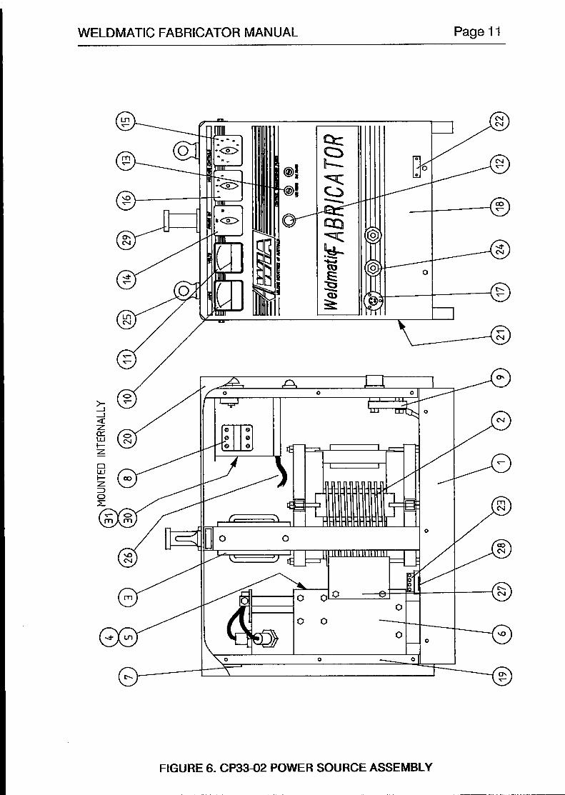
WELDMATIC FABRICATOR MANUAL Page 1 1
FIGURE 6. CP33-02 POWER SOURCE ASSEMBLY
1 ~ ~ ~ . . ~ " ~ "" _ ~ _ ~ . ~ ~ . ~ ~ ~~ ~ ~ ~ ~ ~ ~ " ~ " ~ ~ ~ - ~ ~

~
Page I2 WELDMATIC FABRICATOR MANUAL
99
1 1 iF\ o r
1
a PP gs & 5 e!! $3 g p E EE i% jg :B,,, f a f g p
2 "3& &$&g4 p E 5 Zw"2ggE:; r W w g ,,I,!A qq$:gg&Er@%d+ g8 ;r
~ ~ ~ ~ ~ ~ ~ ~ ~ ~ ~ ~ 8 4 3 8 9 1 ~ ~ ~ ~ ~ ~ U g 5 E 5 5 e
l FF
~ B a x ~ 5 s ~ a 3 = ~ c ~ ~ ~ ~ ~ ~ ~ ~ ~ ~ * -1
! $ "8" c gg @
@ g 4Q; c
r--1 r----- -1 a prrnc In Irn Y e N I =
c
% & 4
5 s I c H
FIGURE 7. CP33-02 CIRCUIT DIAGRAM
- I ~~~~~~~

WELDMATIC FABRICATOR MANUAL Page l 3
7. SAFE PRACTICES IN USING WELDING EQUIPMENT
These notes are provided in the interests of improving operator safety. They should be considered only as a basic guide to Safe Working Habits. A full list of Standards pertaining to industry is available from the Standards Association of Australia, also various State Electricity Authorities, Departments of Labour and Industry or Mines Department and other Local Health or Safety Inspection Authorities may have additional requirements. K I A Technical Note TN7-98 also provides a comprehensive guide to safe practices in welding.
EYE PROTECTION NEVER LOOK AT AN ARC WITHOUT PROTECTION. Wear a helmet with safety goggles or glasses
with side shields underneath, with appropriate filter lenses protected by clear cover lens. This is a MUST for welding, cutting, and chipping to protect the eyes from radiant energy and flying metal. Replace the cover lens when broken, pitted, or spattered.
Recommended shade filter lens.
AmPS TIG MMAW MIG Pulsed MIG 0-100 ............. 10 .................. 9 ................... 10 ................. 12-13 100-150 ......... 11 .................. 10 ................. 10 ................. 12-13 150-200 ......... 12 .................. 10-11 ............ 11-12 ............ 12-13 200300 ......... 13 .................. 11 ................. 12-13 ............ 12-13 300400 ......... 14 .................. 12 ................. 13 ................. 14 400-500 ............................ ” 13 ................. 14 ................. 14 500 + ................................................... ” ” 14 ................. 14
BURN PROTECTION. The welding arc is intense and visibly bright. Its radiation can damage eyes, penetrate lightweight
clothing, reflect from light-coloured surfaces, and bum the skin and eyes. Bums resulting from gas-shielded arcs resemble acute sunburn, but can be more severe and painful.
Wear protective clothing - leather or heat resistant gloves, hat, and safety-toe boots. Button shirt collar and pocket flaps, and wear cuffless trousers to avoid entry of sparks and slag.
Avoid oily or greasy clothing. A spark may ignite them. Hot metal such as electrode stubs and work pieces should never be handled without gloves.
Ear plugs should be worn when welding in overhead positions or in a confined space. A hard hat should be wom when others are working overhead.
Flammable hair preparations should not be used by persons intending to weld or cut.
TOXIC FUMES. Adequate ventilation with air is essential. Severe discomfort, illness or death can result from fumes,
vapours, heat, or oxygen depletion that welding or cutting may produce. NEVER ventilate with oxygen. Lead, cadmium, zinc, mercury, and beryllium bearing and similar materials when welded or cut may
produce harmful concentrations of toxic fumes. Adequate local exhaust ventilation must be used, or each person in the area as well as the operator must wear an air-supplied respirator. For beryllium, both must be used.
Metals coated with or containing materials that emit fumes should not be heated unless coating is removed from the work surface, the area is well ventilated, or the operator wears an air-supplied respirator.
Work in a confined space only while it is being ventilated and, if necessary, while wearing air-supplied respirator.
-

Page 14 WELDMATIC FABRICATOR MANUAL
Vapours from chlorinated solvents can be decomposed by the heat of the arc (or flame) to form PHOSGENE, a highly toxic gas, and lung and eye irritating products. The ultra-violet (radiant) energy of the arc can also decompose trichlorethylene and perchlorethylene vapours to form phosgene. Do not weld or cut where solvent vapours can be drawn into the welding or cutting atmosphere or where the radiant energy can penetrate to atmospheres containing even minute amounts of trichlorethylene or percholorethylene.
FIRE AND EXPLOSION PREVENTION. Be aware that flying sparks OF falling slag can pass through cracks, along pipes, through windows or
doors, and through wall or floor openings, out of sight of the operator. Sparks and slag can travel up to 10 metres from the arc.
Keep equipment clean and operable, free of oil, grease, and (in electrical parts) of metallic particles that can cause short circuits.
If combustibles are present in the work area, do NOT weld or cut. Move the work if practicable, to an area free of combustibles. Avoid paint spray rooms, dip tanks, storage areas, ventilators. If the work can not be moved, move combustibles at least 10 metres away out of reach of sparks and heat; or protect against ignition with suitable and snug-fitting fire-resistant covers or shields.
Walls touching combustibles on opposite sides should not be welded on or cut. Walls, ceilings, and floor near work should be protected by heat-resistant covers or shields.
A person acting as Fire Watcher must be standing by with suitable fire extinguishing equipment during and for some time after welding or cutting if;
Combustibles (including building construction) are within 10 metres.
Combustibles are further than 10 metres but can be ignited by sparks.
Openings (concealed or visible) in floors or walls within 10 metres may expose combustibles to sparks.
Combustibles adjacent to walls, ceilings, roofs, or metal partitions can be ignited by radiant or conducted heat.
After work is done, check that area is free of sparks, glowing embers, and flames. A tank or drum which has contained combustibles can produce flammable vapours when heated.
Such a container must never be welded on or cut, unless it has first been cleaned as described in AS.1674- 1974, the S.A.A. Cutting and Welding Safety Code. This includes a thorough steam or caustic cleaning (or a solvent or water washing, depending on the combustible's solubility), followed by purging and inerting with nitrogen or carbon dioxide, and using protective equipment as recommended in AS.1674-1974. Water-filling just below working level may substitute for inerting.
Hollow castings or containers must be vented before welding or cutting. They can explode. Never weld or cut where the air may contain flammable dust, gas, or liquid vapours.
SHOCK PREVENTION. Exposed conductors or other bare metal in the welding circuit, or ungrounded electrically alive
equipment can fatally shock a person whose body becomes a conductor. Ensure that the machine is correctly connected and earthed. If unsure have machine installed by a qualified electrician. On mobile or portable equipment, regularly inspect condition of trailing power leads and connecting plugs. Repair or replace damaged leads.
Fully insulated electrode holders should be used. Do not use holders with protruding screws. Fully insulated lock-type connectors should be used to join welding cable lengths.
Terminals and Other exposed parts of electrical units should have insulated knobs or covers secured before operation.
I "


![Weldmatic 270 [suits W64-0 wirefeeder] Operators Manual · Weldmatic 270 MIG welder Model No. CP132-2, Iss A 08/12. Welding Industries of Australia An ITW Company Telephone: 1300](https://static.fdocuments.in/doc/165x107/5f45df6d3c7266409706cf10/weldmatic-270-suits-w64-0-wirefeeder-operators-manual-weldmatic-270-mig-welder.jpg)


![Weldmatic 396 [suits W64-0 wirefeeder] Operators …...Weldmatic 396 [suits W64-0 wirefeeder] Operators Manual Weldmatic 396 MIG welder Model No. CP134-2, Iss A 02/12 Welding Industries](https://static.fdocuments.in/doc/165x107/5edb48c3ad6a402d66656bc6/weldmatic-396-suits-w64-0-wirefeeder-operators-weldmatic-396-suits-w64-0.jpg)


![Weldmatic 190 [internal wirefeeder] Operators Manual 190 [internal wirefeeder] Operators Manual Weldmatic 190 MIG welder Model No. CP131-1, Iss A 02/12 uality s eliaility s Performance](https://static.fdocuments.in/doc/165x107/5aa310647f8b9a07758ddcef/weldmatic-190-internal-wirefeeder-operators-190-internal-wirefeeder-operators.jpg)


![Weldmatic 270 [suits W64-0 wirefeeder] Operators Manual · PDF fileCP132-40 Rev D Weldmatic 270 [suits W64-0 wirefeeder] Operators Manual Weldmatic 270 MIG welder Model No. CP132-2,](https://static.fdocuments.in/doc/165x107/5aa007c57f8b9a89178d732b/weldmatic-270-suits-w64-0-wirefeeder-operators-manual-rev-d-weldmatic-270-suits.jpg)