Welding Automation Submerged Arc, TIG, MIG/MAG automatizacija... · Welding Automation The 21st...
98
Welding Automation Submerged Arc, TIG, MIG/MAG COMPLETE SOLUTIONS IN WELDING AND CUTTING FROM ESAB IA00900011
Transcript of Welding Automation Submerged Arc, TIG, MIG/MAG automatizacija... · Welding Automation The 21st...
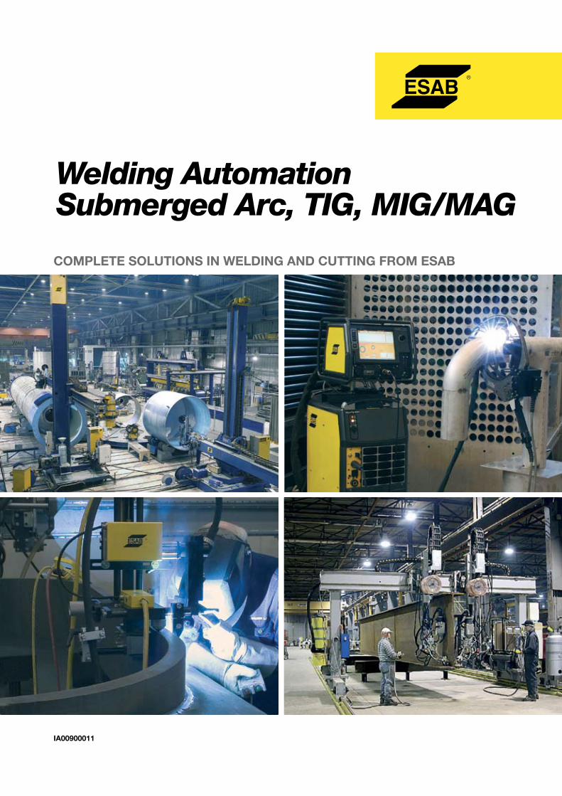
Welding AutomationSubmerged Arc, TIG, MIG/MAG
COMPLETE SOLUTIONS IN WELDING AND CUTTING FROM ESAB
IA00900011
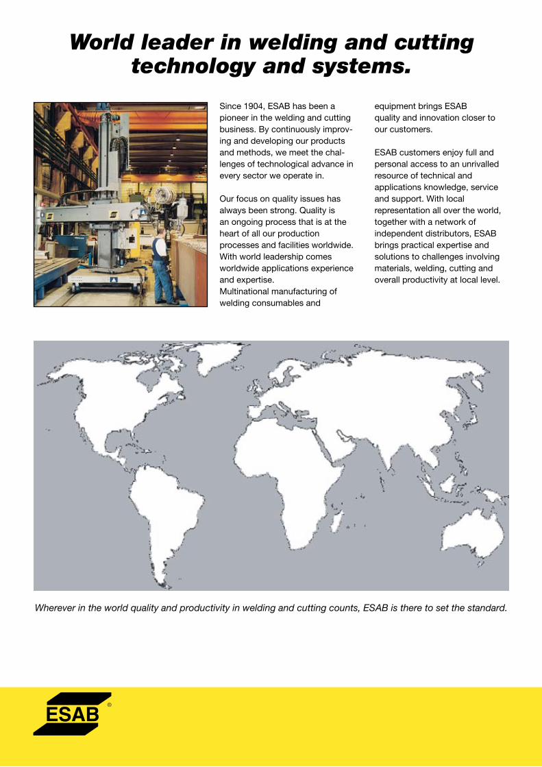
World leader in welding and cutting technology and systems.
Since 1904, ESAB has been a pioneer in the welding and cutting business. By continuously improv-ing and developing our products and methods, we meet the chal-lenges of technological advance in every sector we operate in.
Our focus on quality issues has always been strong. Quality is an ongoing process that is at the heart of all our production processes and facilities worldwide. With world leadership comes worldwide applications experience and expertise.Multinational manufacturing of welding consumables and
equipment brings ESAB quality and innovation closer to our customers.
ESAB customers enjoy full and personal access to an unrivalled resource of technical and applications knowledge, service and support. With local representation all over the world, together with a network of independent distributors, ESAB brings practical expertise and solutions to challenges involving materials, welding, cutting and overall productivity at local level.
Wherever in the world quality and productivity in welding and cutting counts, ESAB is there to set the standard.
Welding AutomationThe 21st Century has brought many new challenges to the metal fabrication industry. Metal fabricators must meet thedemand for increased quality while providing their customers with an overall lower cost. Productivity is challenged by theshortage of skilled workers and the added health and safety concerns for these workers. Profitability is under continuedpressure from intense global competition. As a result, manufacturers are required to utilize new fabrication techniques tobuild increasingly complex designs and structures.
ESAB is committed to providing the necessary solutions to keep you competitive. Whether your metal fabrication projectrequires simple components such as tractors or requires large turn-key systems and production lines, ESAB offers a fullrange of automation products to meet every need. At ESAB, we consistently offer the best welding solutions to meet theever changing challenges of the metal fabrication industry.
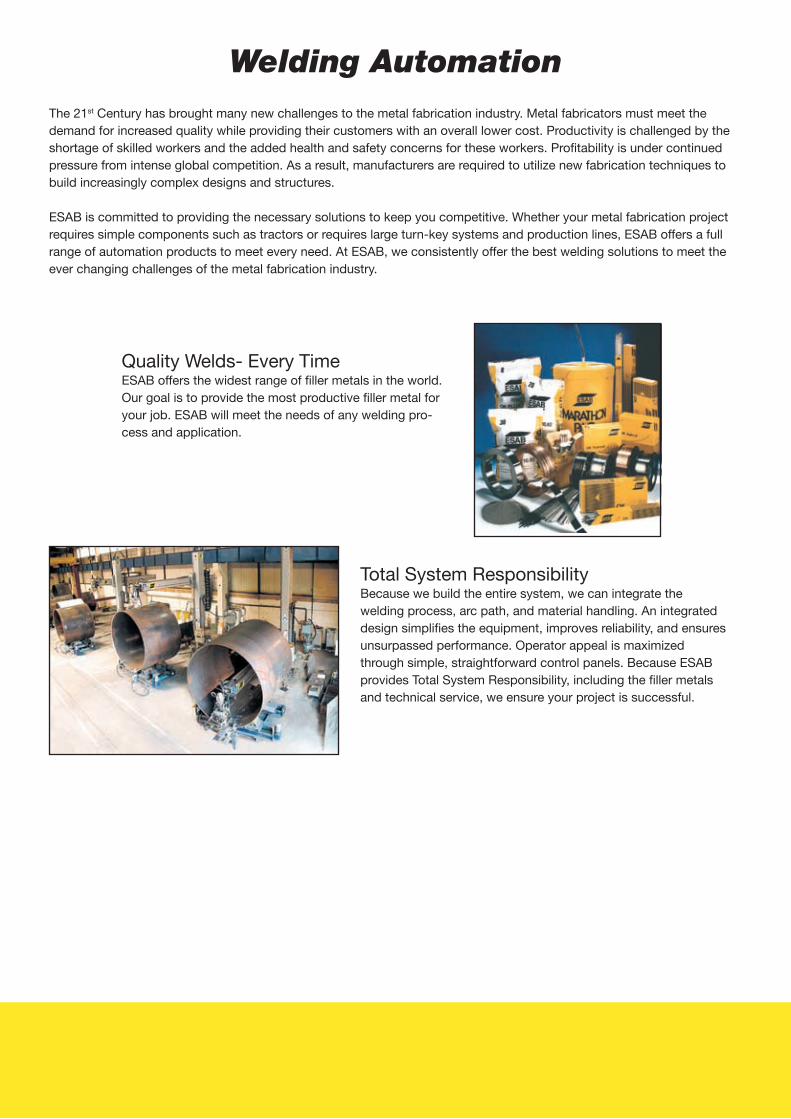
Quality Welds- Every TimeESAB offers the widest range of filler metals in the world. Our goal is to provide the most productive filler metal for your job. ESAB will meet the needs of any welding pro-cess and application.
Total System ResponsibilityBecause we build the entire system, we can integrate the welding process, arc path, and material handling. An integrated design simplifies the equipment, improves reliability, and ensures unsurpassed performance. Operator appeal is maximized through simple, straightforward control panels. Because ESAB provides Total System Responsibility, including the filler metals and technical service, we ensure your project is successful.
2
TABLE OF CONTENTS
Tractors PagesRailtrac 1000 ............................................................................................................. 4-6Miggytrac 1001-2000 ................................................................................................ 7Miggytrac 3000 ......................................................................................................... 8A2 Multitrac with PEH Process Controller ................................................................. 9A2 Multitrac – Accessories and Options ................................................................... 10A2 Tripletrac .............................................................................................................. 11A6 Mastertrac ............................................................................................................ 12A6 DK ........................................................................................................................ 13Frametrack ................................................................................................................ 14A2/A6 Wear parts ...................................................................................................... 15-18
Controllers and Power SourcesPEH Process Controller ............................................................................................. 19LAF DC Power Sources ............................................................................................. 20TAF AC Power Sources ............................................................................................. 21
Weld HeadsA2S Mini Master ........................................................................................................ 22A2 Component System Modularization .................................................................... 23A6S Arc Master ......................................................................................................... 24A6 Component System Modularization .................................................................... 25A6S Tandem .............................................................................................................. 26-27A6S Compact ............................................................................................................ 28A6S SAW Strip Cladding Head ................................................................................. 29A6S ESW Strip Cladding Head ................................................................................. 29MHW Automatic Head for Manhole Welding ............................................................ 30
Accessory ComponentsA6 Synergic Cold Wire .............................................................................................. 31A6B Beam Carriage ................................................................................................... 32Motorized Slides ........................................................................................................ 33PAK and GMD - Joint Tracking Systems ................................................................... 34-35OPC – Flux Recovery Systems ................................................................................. 36-37FFRS – Flux Feed Recovery Systems ....................................................................... 38-39CRE – Air Drying Equipment ..................................................................................... 40Camera Systems ....................................................................................................... 41Weldoc WMS4000 Software ..................................................................................... 42
Handling EquipmentTA Turning Rolls ......................................................................................................... 43TNA Turning Rolls ...................................................................................................... 44TXA Turning Rolls ...................................................................................................... 45AHMA Positioners ..................................................................................................... 46SKA Positioners ......................................................................................................... 47SHA Positioners ........................................................................................................ 48FA Positioners ........................................................................................................... 49CRA Positioners ........................................................................................................ 50Head anf Tailstock ..................................................................................................... 51-52

3
TABLE OF CONTENTS
Mechanized TIG PagesAristo MechTig - Aristo Mech Control ....................................................................... 53-54A21 – Weld Heads PRB, PRC, PRD, POC, PRH ....................................................... 55-60A25 – Components System ....................................................................................... 61MEI 21/10 – Wire Feeder ........................................................................................... 62G-Tech Tungsten Grinder .......................................................................................... 63
RoboticsAristo Robot Package ............................................................................................... 64-65
Applied AutomationMechtrac ................................................................................................................... 66Manipulators - CaB S, M, C versions ........................................................................ 67-71External / Internal Seamers ....................................................................................... 72-73Circotech ................................................................................................................... 74Rototech 80 ............................................................................................................... 75
Special Application ProductsWind Energy Industry ................................................................................................ 76-77Beam Welding Systems ............................................................................................ 78-79Welding Gantries ....................................................................................................... 80Shipyard Applications ............................................................................................... 81Custom Welding Solutions ........................................................................................ 82-83Friction Stir Welding .................................................................................................. 84-85Narrow Gap ............................................................................................................... 86-87
Mechanized Cutting SystemsCutting Processes ..................................................................................................... 88-89Esab Precision Plasma .............................................................................................. 90Numeric Controls – Offl ine Programming.................................................................. 91Ultrarex UXC/UXL-P – E-Vent ................................................................................... 92Combirex CXL-P – Eagle ........................................................................................... 93Suprarex SXE-P Series .............................................................................................. 94Numorex NXB – Telerex TXB – Alpharex AXD ........................................................... 95

4
Railtrac 1000A unique, fl exible, multi-purpose system for welding and cutting
• Create suitable solutions for most applications• Consists of aluminum and steel parts to withstand harsh environments• Welding possibilities include horizontal to horizontal and vertical (up only)• Practical accessories available• New joint system allows for both stiff and fl exible rail applications• Straightforward and well designed programming unit with up to 5 different programs• Standard software offers programmable interval welding and backfi ll function• Remote control allows functionality without lifting welding visor• Buttons featured on remote control include: start and stop, shift program, weaving width, zero line displacement, and many more• Adjust the welding current and voltage during welding with only two potentiometers on the remote control (when using ESAB equipment)• Remote control only available on FW1000 and FWR1000 models
Instruction Manual Railtrac 1000 (F, FR), order number ....................................0777167001Instruction Manual Railtrac 1000 (FW, FWR), order number .............................0777168001Instruction Manual Railtrac 1000 (BV, BVR)), order number ..............................0777169001Sales Literature Railtrac 1000 (F, FR), order number ........................................XA00086720Sales Literature Railtrac 1000 (FW, FWR), order number .................................XA00086720Sales Literature Railtrac 1000 (BV, BVR), order number ...................................XA00086720
Technical Data Railtrac F1000Flexi
Railtrac FW1000(L)Flexi Weaver
Railtrac FR1000Flexi Return
Railtrac FWR1000Flexi Weaver Return
Power supply (VAC/VDC) 36-46/40-60 36-46/40-60 36-46/40-60 36-46/40-60Power consumption (Max) (W) 30 80 30 80Weight excl. rail, Kg 6 7 6 7Measurements, LxWxH, mm 170x400x190 170x350x190 170x400x190 170x350x190Rail measurements-fl exi rail, mm 60x5 60x5 60x5 60x5Stiffener bar, mm 40x10 40x10 40x10 40x10Min bend diameter externally, mm 3000 3000 3000 3000Slide for height adjustment, mm ± 22 ± 22 ± 22 ± 22Mechanical lateral adjustment, mm ± 35 ± 35Welding speed, cm/min 10-150 10-150 10-150 10-150Quick transport, cm/min 150 150 150 150Preheating time (s) 0.0-9.9 0.3 0.0-9.9 0.3Interval welding, cm 1-99 1-99 1-99 1-99Crater-fi lling time (s) 0.0-9.9 0.0-9.9 0.0-9.9 0.0-9.9“Backfi ll”, mm 0-99 0-99 0-99 0-99Weaving speed, mm/s - 6-60 6-60Weaving width, mm 1-30 1-30Electrical 0-line displacement, mm ± 12.5 ± 12.5Pause time at outer edge, (s) 0.0-9.9 0.0-9.9Weaving pattern (No.) 3 3Number of programs 5 5 5 5Temp. machine and magnets (°C) 0-70 0-70 0-70 0-70Temp. vacuum attachment (°C) 0-90 0-90 0-90 0-90Safety class (DIN 40050) IP 23 IP 23 IP 23 IP 23
TRACTORS
5
TRACTORS
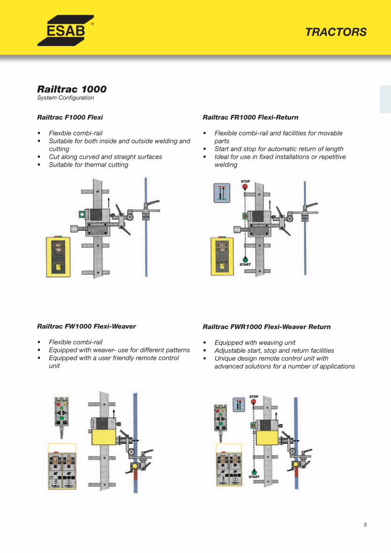
Railtrac 1000System Confi guration
Railtrac FWR1000 Flexi-Weaver Return
• Equipped with weaving unit• Adjustable start, stop and return facilities• Unique design remote control unit with advanced solutions for a number of applications
Railtrac F1000 Flexi
• Flexible combi-rail• Suitable for both inside and outside welding and cutting• Cut along curved and straight surfaces• Suitable for thermal cutting
Railtrac FR1000 Flexi-Return
• Flexible combi-rail and facilities for movable parts• Start and stop for automatic return of length• Ideal for use in fi xed installations or repetitive welding
Railtrac FW1000 Flexi-Weaver
• Flexible combi-rail• Equipped with weaver- use for different patterns• Equipped with a user friendly remote control unit

6
Railtrac 1000System Confi guration
Ordering Information
Railtrac F1000 Flexi .............................................. 0398 146 002Railtrac FW1000 Flexi-Weaver............................. 0398 146 012Railtrac FR1000 Flexi-Return .............................. 0398 146 003Railtrac FWR1000 Flexi-Weaver Return ............. 0398 146 013
TRACTORS
Options and AccessoriesRailtrac F1000Flexi
Railtrac FW1000 (L)Flexi Weaver
Railtrac FR1000
Flexi Return
Railtrac FWR1000
Flexi Weaver Return
Ordering Information
Basic Equipment (Standard)Weaving unit * *Control unit * * * *Remote control * *Universal torch holder with slide * * * *Automatic start and stop function * *Rails and attachments (Components)Flexible alu-rail, 2.5 m * * * * 0398 146 115Flexible alu-rail, 2.5 m, 8 magnets * * * * 0398 146 112Flexible alu-rail, 2.5 m, 4 vac. Attachm. * * * * 0398 146 113Stiffener bar, 2.5 m * * * * 0398 146 116Magnetic attachment, at least 8/2.5 m *(1) * * * * 0398 146 100Vacuum attachment, at least 4/2.5 m * * * * 0398 146 104Screw attachment for stiffened rail * * * * 0398 146 114AccessoriesTorch holder PSF 400/500 * * * * 0398 145 101Adapter for a majority of existing attachments to the stiffened rail
* * * * 0398 146 106
Universal pivoted torch holder * * * * 0398 145 104Attachment for IMP cutting torch * * * * 0398 145 260Torch and attachment * * * * 0398 145 215Tilt unit for weaving unit * * 0398 145 200Turning unit for weaving unit * * 0398 145 201“Floating” head * * * * 0398 145 211IMP cutting torch * * * * 0398 145 250Transport and storage box * * * * 0398 145 199*(1) 2 pcs in each bag

7
TRACTORS
Miggytrac 1001-2000The perfect complement to your MIG power source
Ordering Information
Miggytrac 1001, 42 VAC ………............................. 0457 357 881Miggytrac 2000, 42 VAC ………............................. 0457 358 880Welding screen .......................................................0457 463 880
Instruction Manual Miggytrac 1001,order number .............................................0457572001Instruction Manual Miggytrac 2000,order number .............................................0449310001Sales literature Miggytrac 1001, order number .................................................XA00086520Sales literature Miggytrac 2000, order number .................................................XA00104720
• Small and compact• Accomodates any standard welding torch• Four-wheel drive system ensures even
and stable movement• Drives itself against work pieces• Additional functions include setting
travel speed, magnet on/off for freewelding and welding on/off
• Equipped with two manual slides forfi ne corrections of torch position
• Includes rotating slide which allowsprecise torch angle manipulation
• Continuous and interval welding(Miggytrac 2000 only
Options and Accessories
Control Cable ESAB, 5mt ....................................... 0457 360 880 (12 pin male- 23 pin male Burndy style). For all MEK (also requires 457 462 880), ESABFeed, and ARISTOFeed feeders (also requires 458 757 881)ESAB MEK Wire Feeder Adaptor kit .......................0457 462 880 (Required for connection of Miggytrac to MEK feeders)ESAB ARISTOFeed ...................................................0459 491 911 (Required for connection of Miggytrac to ARISTOFeed)Universal Control Cable, 5mt ..................................0457 360 881 (12 pin male Burndy style-open end). Requires user-supplied plug to connect cable to OEM feedersTransformer kit, 220-42 VAC ....................................0457 467 880 Universal kit used to adapt 115 VAC wire feeders to Miggytrac
Technical Data 1001 2000Control voltage 36-46 V AC 36-46 V ACPower 20 W 40 WWelding speed, mm/min 150-1200 150-1500Dimensions (LxWxH), mm 266x257x267 330x260x360Weight, kg 7 9,5Adjustment of slide, mm ± 20 ± 17Connection Burndy, 12 pins Burndy, 12 pinsRemote control outlet Volt and Ampere (wire feed speed) Volt and Ampere (wire feed speed)Welded interval, mm no 10-990Non-welded interval, mm no 10-990Backfi ll, sec no 0,3Crater-fi ll time , sec no 0-9,9Fast positioning speed, mm/min no 2500
(mm)
Miggytrac 1001
Miggytrac 2000
Miggytrac 1001 Miggytrac 2000
(mm)

8
TRACTORS
Miggytrac 3000The most versatile and compact solution for fi llet semiautomatic welding
Ordering Information
Miggytrac 3000, 42 VAC ..........................................0457 359 880
Instruction Manual Miggytrac 3000,order number .............................................0449453001Sales literature Miggytrac 3000, order number .................................................XA00123620
• Small, lightweight and complete with on-board wire feeder and water cooling• Four-wheel drive system ensures even and stable movement• Control panel for carriage movement, wire-feeder,
continuous or interval welding• Programmable functions for Crater-fi ll / Backfi ll• For wire spools up to 20 kg• Adjustable pre and post gas
Options and Accessories
Contact tip, 1 mm CO2 .......................................... 0468 502 005Contact tip, 1,2 mm CO2 ....................................... 0468 502 007Contact tip, 1,4 mm CO2 ....................................... 0468 502 008
Cooled gas nozzle ................................................... 0449 903 10115 m cable for Origo™Mig - Aristo™Mig .............. 0469 836 887Steel wheels (4 pieces) ............................................0457 357 081
(mm)
Technical Data 3000Control voltage 36-46 V ACPower 80 WWelding speed, mm/min 150-1500Dimensions (LxWxH), mm 370x400-530x520Weight, kg 17Adjustment of slide, mm ± 17Connection Burndy, 23 pinsRemote control outlet Volt e Ampere (wire feed speed)Welded interval, mm 10-990Non-welded interval, mm 10-990Backfi ll, mm 0-99Crater-fi ll time, sec 0-99Wire feed speed, m/min 2-25Gas pre-fl ow / post-fl ow, sec 0-99Fast positioning speed, mm/min 2500

9
A2 Multitrac (PEH)The universal welding tractor
Instruction Manual SAW, order number ....................................... 0449165060Instruction Manual GMAW MTW 600, order number (MTW) ..... 0449165060Instruction Manual MTW 600, order number ............................... 0449006001Sales Literature SAW, order number ........................................... XA00105420Sales Literature GMAW, order number ........................................ XA00105520
Ordering InformationA2 Multitrac GMAW ……...…………................................ 0449 161 880A2 Multitrac GMAW MTW 800 ….................................... 0449 161 881A2 Multitrac SAW ..............................................................0449 160 880
• Compact and effi cient design allows for easymovement between work pieces
• Self-propelled, four-wheel drive for stable,accurate, and constant operation
• PEH Process Controller with digital display, allowspresetting and control of welding parameters(for more info on PEH Controller, see page 19)
• Horizontal, vertical and rotary slides allow for quickadjustment of weld nozzle into various positions
• Reliable mechanical parts, even under harshenvironments
• For use with LAF (DC) or TAF (AC) power sources• Many specially developed accessories available• Minimal inside diameter 1300 mm
Options and AccessoriesAccessories...................................................................... page 10Feed rolls, contact tips .............................................. page 15-18Power supplies ........................................................... page 20-21Control cables ............................................................. page 20-21
TRACTORS
Technical Data SAWWire dimensions, mm Steel
Stainless Cored Wire
1.6-5.01.6-4.01.6-4.0
Max wire feed speed, m/min > 9Electrode weight, kg 30Flux volume, l 6Weight excl. wire and fl ux, kg 47Permissable load 100%, A 800Control voltage, V 42Travel speed, m/min 0.1-1.7Linear slides setting length, mm 90Rotary slide setting angle 360°
Technical Data GMAW GMAW MTW 600Wire dimensions, mm Steel Stainless Cored Wire Aluminum
0.8-1.6 1.0-1.60.8-1.6 1.0-1.61.2-2.4 1.0-2.41.2-1.6 1.0-2.0
Max wire feed speed, m/min >16 >25Electrode weight, kg 30 30Weight excl. wire and fl ux, kg 43 43Permissable load 100%, A 600 600Control voltage, V 42 42Travel speed, m/min 0.1-1.7 0.1-1.7Linear slides setting length, mm 90 90Rotary slide setting angle 360° 360°

10
A2 Multitrac (PEH)
Dimensions (mm)
Options and Accessories GMAW SAWAuxiliary guiding equipment
Guide wheel bogie 0413 542 880 * *Idling roller 0333 164 880 * *Guide bar 3 m 0000 909 185 * *V-guide wheel 0333 098 881 * *V-wheeltrack in steel 0443 682 881 * *Loop for connection of two tractors 0334 680 881 * *Pilot lamp, light-bulb 0153 143 885 * *Pilot lamp, laser diode 0457 788 884 * *
Wire reelWire reel, plastic, 30 kg 0153 872 880 *Wire reel, steel, 30 kg 0416 492 880 *
Flux handling equipmentFlux recovery unit OPC 0148 140 880 *Bracket suction 0332 947 880 *Flux hopper of silumin alloy 0413 315 881 *Concentric fl ux feeding funnel, D20 0145 221 881 *Contact tube, bent 0413 511 001 *
TRACTORS

11
TRACTORS
A2 TripletracFor internal circumferential welding
Instruction Manual A2 Tripletrack, order number ........... 0449435104Sales Literature A2 Tripletrack, order number ............... XA00118220
• Increase productivity and quality• Ideal for internal circumferential welding
of large cylindrical objects that are rotatingon a turning roll system
• Heavy duty feed unit secures an even and stable wire feed for a top quality and homogenous weld
• Delivered with the digital A2-A6 Process Controller (PEH)
• Unique steering system allows operator tosimultaneously adjust the wheel and torch positionfor an accurate and effortless seam tracking
• Control equipment is easy to use and requiresminimal training
• Choose between start methods, burn-back timesand other settings
Ordering Information A2 Tripletrac with PEH .......................... 0449 430 880
Options and AccessoriesAccessories ......................................................... page 10Feeds rolls, contact tips .............................. page 15-18Power supplies ............................................. page 20-21Control cables ............................................... page 20-21
Technical Data SAW
Wire dimensions, mm Steel Stainless Cored Wire
1.6-4.0
1.6-4.0
1.6-4.0
Max wire feed speed, m/min > 9
Electrode weight, kg 30
Flux volume, l 6
Weight, excl. wire and fl ux, kg 47
Permissable load 100%, A 800
Control voltage, V 42
Travel speed, m/min 0.1-1.7
Linear slides setting lenght, mm 90
Rotary slide setting angle 360°
Options & Accessories SAW
Auxiliary guiding equipmentPilot lampe, light-bulb (PEH) 0153 143 885Pilot lampe, laser diode (PEH) 0457 788 884Utility light 0000 932 048
Flux handling equipmentFlux recovery unit OPC 0148 140 880Bracket suction 0332 947 880Flux hopper of Silumin alloy 0413 315 881Concentric fl ux feeding funnel, D20 0145 221 881Contact tube, bent 0413 511 001
Wire reelWire reel plastic, 30 kg 0153 872 880Wire reel steel, 30 kg 0416 492 880

12
A6 MastertracFor heavy duty arc welding
Ordering Information
A6 Single Mastertrac, standard ............................. 0449 260 880 156:1 feed motor (wire feed speed range of 0,2-4,0 m/min)A6 Single Mastertrac, high speed ......................... 0449 260 890 74:1 feed motor (wire feed speed range of 0,8-16 m/min)A6 Tandem Mastertrac, complete ......................... 0334 191 882
• Self-propelled, four-wheel drive for stable,accurate, and constant operation
• Available in three different wire confi gurationdesigns: Single, Twin, or Tandem
• Ample capacity for heavy production weldingand can take up to 6 mm (1/4 in) wire using1500 Amps (DC or AC)
• PEH Process Controller with digital display allows for preset accuracy in all welding parameters
• Designed for use with LAF (DC) or TAF (AC)power sources
• Many specially developed accessories available
Options and AccessoriesFeed rolls, contact jaws ............................................ page 15-18Power supplies ........................................................... page 20-21Control cables ............................................................. page 20-21
Instruction Manual A6 Mastertrac (SAW), order number ...................0449265060Instruction Manual A6 (GMAW) Mastertrac, order number ...............0456503001Instruction Manual A6 Tandem Mastertrac, order number ...............0456503001Sales Literature A6 Mastertrac, order number ................................. XA00085120
TRACTORS
Options & Accessories Contact equipment heavy Twin Arc, complete 0334 291 889Wire reel, plastic 30 kg 0153 872 880Wire reel, steel 30 kg 0416 492 880Wire reel, steel, 30-100 mm adjustable 0449 125 880Brake hub heavy duty 0146 967 880Rebuilding kit GMAW 0334 299 890Strip cladding kit 0155 972 880Flux hopper holder for strip cladding 0148 107 003Flux recovery nozzle, strip 0156 025 001Concentric fl ux funnel, D35 0254 900 880Flux funnel insert 0254 900 301Angular slide 0671 171 580Pilot lamp, light-bulb 0153 143 885Pilot lamp, laser diode 0457 788 884Flux recovery unit OPC 0148 140 880Bracket suction 0332 947 880Idler rollers (2 required) 0333 164 880Guide wheel, fi llet 0671 125 780Magnetic guide rail, 3m 0154 203 880Carbon arc gougingRebuilding kit carbon arc gouging 0153 592 880VEC-motor, 312:1 to be used for carbon arc gouging 0145 063 905
13
TRACTORS
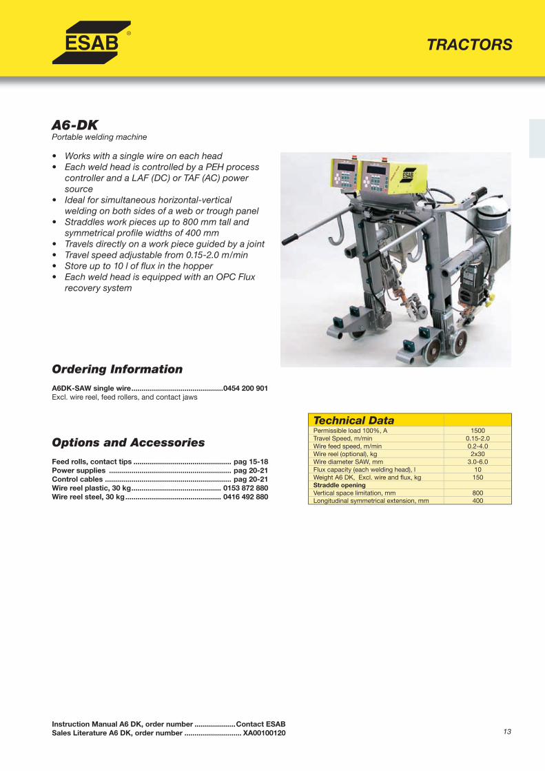
A6-DKPortable welding machine
• Works with a single wire on each head• Each weld head is controlled by a PEH process
controller and a LAF (DC) or TAF (AC) power source
• Ideal for simultaneous horizontal-verticalwelding on both sides of a web or trough panel
• Straddles work pieces up to 800 mm tall and symmetrical profi le widths of 400 mm
• Travels directly on a work piece guided by a joint• Travel speed adjustable from 0.15-2.0 m/min• Store up to 10 l of fl ux in the hopper• Each weld head is equipped with an OPC Flux
recovery system
Instruction Manual A6 DK, order number ....................Contact ESABSales Literature A6 DK, order number ............................ XA00100120
Ordering Information A6DK-SAW single wire .............................................0454 200 901Excl. wire reel, feed rollers, and contact jaws
Options and AccessoriesFeed rolls, contact tips ................................................ pag 15-18Power supplies ............................................................ pag 20-21Control cables .............................................................. pag 20-21Wire reel plastic, 30 kg ............................................ 0153 872 880Wire reel steel, 30 kg ............................................... 0416 492 880
Technical DataPermissible load 100%, A 1500Travel Speed, m/min 0.15-2.0Wire feed speed, m/min 0.2-4.0Wire reel (optional), kg 2x30Wire diameter SAW, mm 3.0-6.0Flux capacity (each welding head), l 10Weight A6 DK, Excl. wire and fl ux, kg 150Straddle openingVertical space limitation, mm 800Longitudinal symmetrical extension, mm 400

14Frametrac Sales Literature, order number ........................... XA00126620Frametrac Instruction Manual, order number ......................0460 072 001
Frametrac™ for Welding Windtower Door Frames
• Compact, motor-powered tractor that travels on the door frame to be welded.
• Four driving wheels guarantee even, stablemovement on the frame.
• Standard ESAB torch can be attached andadjusted to fi t the frame and type of welding.
• Control travel direction and speed, weaving speed and width from the control box and remote control.
• The Automatic Current Control (ACC) holds the arc length stable to secure the best possible arc.
• Use directly on frames with a constant thickness of 20-75 mm.
Technical DataControl Voltage, VAC 36-46Power, W 80Welding speed, cm/min 10-99Frame Width, mm 20-50Min. Radius on Frame, mm 150Min. Height on Frame, mm 40Max. Height Difference on Frame, mm 120Dimensions, LxWxH, mm 280x430x508Weight, excl. wire reel, kg 30
Ordering Information Frametrac with ACC ................................................ 0449 925 880
Options and Accessories Spring arms for frames 50-75 mm ........................... 0449 904 025Connection cable .................................................... 0457 360 880
TRACTORS

15
A2/A6 Tractor Wear Parts
Accessories: GMAW MTW 600Wire Diameter Wire Material Type Part Number Wear Insert (liner) Type Ref. Item
mm Fe Ss Cw Al Steel Tefl on Tefl on Brass
1.0 * * * 0457 625 005 A A
1.0 * 0457 625 005 B B
1.2 * * * 0457 625 006 A A
1.2 * 0457 625 007 B B
1.4 * * * 0457 625 008 A A
1.6 * * * 0457 625 009 A A
1.6 * 0457 625 009 B B
1.6 * * * 0457 625 010 A A
1.6 * 0457 625 010 B B
2.0 * * 0457 625 011 D D
2.0 * 0457 625 011 C C
2.4 * * 0457 625 012 D D
2.4 * 0457 625 012 C C
Technical Reference KeyProcess Duty Type Contact Tube Contact Tips / Jaws
A2 Contact Equipment
SAW, single wire Light-Duty D20 M12
SAW, twin wire Light-Duty D351 M6
GMAW, 2WD Light-Duty D35 M10 or M6 with adaptor
GMAW, 4WD Light-Duty MTW 600 M8
A6 Contact Equipment
SAW, single wire Light-Duty D20 M12
SAW, twin wire Light-Duty D35 M6
SAW, single or twin wire Heavy-Duty D35 Contact Jaws
SAW, compact Heavy-Duty D35 Contact Jaws
GMAW, single wire only Light-Duty D35 M10 or M6 with adaptor1 D35 twin wire adaptor – P/N 333 772 001
Reference Item Wear Insert (liner) Type Wire Diameter, mm Part Number
A Steel Spiral 1.0-1.6 0457 454 002
B Tefl on Insert 1.0-1.6 0457 619 001 (to be cut to length when mounting)
C Tefl on Insert 2.0-2.4 0457 619 002 (to be cut to length when mounting)
D Brass Tube 2.0-2.4 0457 620 002
A2 Wear Parts Catalogue, part number......................................................... XA00115820A2 GMAW (MIG) Wear Parts Brochure, part number ................................... XA00126820A6 Wear Parts Catalogue, part number......................................................... XA00125820
TRACTORS

16
TRACTORS
A2/A6 Tractor Wear Parts, cont’d
Feed RollersWire Diameter
mm Part Number
SAW Feed roller, single wire0.8 0145 538 8811.0 0145 538 8821.2 0145 538 8831.6 0218 510 2812.0 0218 510 282
2.4-2.5 0218 510 2833.0-3.2 0218 510 298
4.0 0218 510 2865.0 0218 510 2876.0 0218 510 288
Pressure Roller 0153 148 880
SAW Feed roller, single wire, knurled V-groove0.8-1.6 0146 024 8802.0-4.0 0146 024 8813.0-5.0 0218 510 299
Pressure Roller 0153 148 880
GMAW Feed roller, single wire, 2WD drive, knurled U-groove
0.8-1.6 0146 024 8802.0-4.0 0146 024 881
Pressure Roller0.8-1.6 0146 025 880*2.0-4.0 0146 025 881*
*Shaft for pressure roller 0212 901 101
SAW Feed roller, twin wire2x1.2 2x 0218 522 4862x1.6 2x 0218 522 4882x2.0 2x 0218 522 484
2x2.4-2.5 2x 0218 522 4802x3.0-3.2 2x 0218 522 481
Pressure roller (spherical type with shaft) 0218 524 580
SAW Feed roller, twin wire, knurled U-groove2x2.0-3.2 2x 0148 772 880
Pressure roller (spherical type with shaft) 0218 524 580
GMAW Feed roller, single wire, 4WD0.6-0.8 0369 557 001
0.8-0.9*** 0369 557 0010.8-1.0 0369 557 0021.0-1.2 0369 557 003
1.0-1.2** 0369 557 0061.2-1.6 0369 557 0071.4-1.6 0369 557 0131.6** 0369 557 0082.0** 0369 557 009
2x1.2 2x 0369 557 010Pressure roller (fl at roller) 0369 728 001
GMAW Feed roller, single wire, knurled, 4WD**1.0-1.2/1.4-1.6 0369 557 004
1.4-1.6/2.0-2.4 369 557 005 0369 557 005Pressure roller (knurled roller) 0466 262 001
** Aluminum only *** For Cored Wire
Idling pressure roller
Driving feed rollerwith groove
Idling pressure roller
Driving feed rollerwith knurled groove
Geared driving feed and pressure roller with knurled groove, eg/soft Tubular wire
Spherical idling pressure roller for equal distributed pressure on the two wires
Driving feed with grooves for twin wire system
17
TRACTORS
A2/A6 Tractor Wear Parts, cont’d
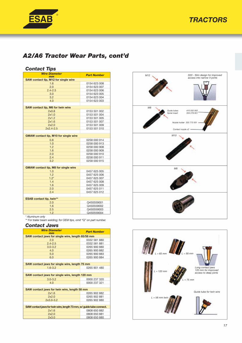
Contact TipsWire Diameter
mm Part Number
SAW contact tip, M12 for single wire1.6 0154 623 0082.0 0154 623 007
2.4-2.5 0154 623 0063.0 0154 623 0053.2 0154 623 0044.0 0154 623 003
SAW contact tip, M6 for twin wire2x0.8 0153 501 0022x1.0 0153 501 0042x1.2 0153 501 0052x1.6 0153 501 0072x2.0 0153 501 009
2x2.4-2.5 0153 501 010
GMAW contact tip, M10 for single wire
0.8 0258 000 9141.0 0258 000 9131.2 0258 000 9081.6 0258 000 9092.0 0258 000 9102.4 0258 000 9113.2 0258 000 915
GMAW contact tip, M8 for single wire1.0 0457 625 0051.2 0457 625 0061.2* 0457 625 0071.4 0457 625 0081.6 0457 625 0092.0 0457 625 0112.4 0457 625 012
ESAB contact tip, twin**2.0 Q4505590011.6 Q4505590022.5 Q4505590031.2 Q450559004
* Aluminum only** For trailer beam welding; for OEM tips, omit “Q” on part number.
Contact JawsWire Diameter
mm Part Number
SAW contact jaws for single wire, length 65/58 mm2.0 0332 581 880
2.4-2.5 0332 581 8813.0-3.2 0265 900 880
4.0 0265 900 8825.0 0265 900 8836.0 0265 900 884
SAW contact jaws for single wire, length 75 mm1.6-3.2 0265 901 480
SAW contact jaws for single wire, length 120 mm
3.0-3.2 0000 237 3204.0 0000 237 321
SAW contact jaws for twin wire, length 58 mm2x1.6 0265 902 8822x2.0 0265 902 881
2x3.0-3.2 0265 902 880
SAW contact jaws for twin wire, length 73 mm, w/ guide tube connect.2x1.6 0808 650 8822x2.0 0808 650 8812x3.0 0808 650 880
D20 - Slim design for improved access into narrow V-joints
Guide tubes 415 032 002Spiral insert 334 279 001
Nozzle holder 333 772 001
Contact nozzle x2
M12
M8
M10
M8
L = 65 mm L = 58 mm
L = 120 mm
L = 75 mm
L = 58 mm twin
Long contact jaws120 mm for improved access to deep joints
Guide tube for twin wire
18
TRACTORS
A2/A6 Tractor Wear Parts, cont’d
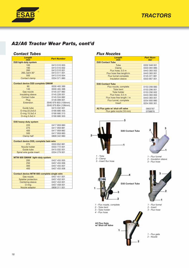
Flux NozzlesLength
mm Part Num-
berD20 Contact Tube
Tube 0332 948 001Clamp 0333 094 880
Flux hose, 0.5 m 0443 383 002Flux hose free length/m 0443 383 001
Flux funnel complete 0145 221 881Insulation sleeve 0333 667 001
D35 Contact TubeFlux nozzle, complete 0153 299 880
Tube bent 0153 296 001Tube holder 0153 290 002
Flux hose, 0.5 m 0443 383 002Flux hose free length / m 0443 383 001
Flux tunnel, complete 0254 900 880Insert 0254 900 301
A2 Flux gate w/ shut-off valve 0903787Flux gate nozzle (18 mm) 0708876
1 - Tube2 - Clamp3 - Insert fl ux hose
1 - Flux funnel2 - Insulation sleeve3 - Flux hose
D20 Contact Tube
A2 Flux Gatew/ Shut-off Valve
1 - Flux funnel2 - Insert3 - Flux hose
1 - Flux nozzle, complete2 - Tube bent3 - Tube holder4 - Flux hose
1 - Flux gate2 - Nozzle
D35 Contact Tube
Contact TubesLength
mm Part Number
D20 light-duty system 100 0413 510 003190 0413 510 002260 0413 510 001
260, bent 30° 0413 511 001500 0413 510 004
Contact clamp 0334 571 880
Contact device D20 complete GMAW90 0030 465 389140 0030 465 388
Gas nozzle 0145 227 882Insulating sleeve 0145 226 001
Contact tube 0145 534 882Plug 0146 099 001
Extension 0040 979 803 (158mm)0040 979 804 (108mm)
Guide tube 0415 032 001O-ring 22.2x3.0 0190 680 405O-ring 15.3x2.4 0190 680 313O-ring 5.3x2.4 0190 680 303
D35 heavy-duty system
220 0417 959 880275 0417 959 881400 0417 959 882500 0417 959 883
Clamp half 0809 342 880
Contact device D35, complete twin wire275 0333 852 881
Nozzle holder 0333 772 001Guide tube 0415 032 001
Spiral wire guide insert 0334 279 001
MTW 600 GMAW light-duty system200 0457 455 005250 0457 455 006300 0457 455 007400 0457 455 008
Contact device MTW 600 complete single wireGas nozzle 0457 451 001
Splatter protection 0457 452 001Centering sleeve 0457 453 001
O-ring 0457 458 001Nozzle adaptor 0808 311 001

19
CONTROLLERS AND POWER SOURCES
Instruction Manual PEH Controller (4.0 >), order number ............... 0443745001Instruction Manual PEH Controller (4.0 <), order number ............... 0443745160Sales Literature PEH Controller, order number ................................ XA00089320
A2-A6 Process Controller (PEH)
• Designed for use with ESAB’s LAF (DC)and TAF (AC) power sources
• Suitable for MIG or SAW processes• Preset all welding parameters by keying values on
front panel; can store up to 10 different data sets in memory for easy recall during welding
• Submenus let user decide on welding direction, wire type/dimension, and weld start/stop
• Microprocessor automatically fi ne tunes arccharacteristics depending on wire type andparameters selected
• Microprocessor controlled system is userfriendly and requires minimal training
• Choose between 12 different languages andview heat input on display
Ordering InformationA2-A6 PEH Process Controller ............................ 0443 741 880
AccessoriesControl cable, 15 m .............................................. 0449 449 880Control cable, 25 m .............................................. 0449 449 881Control cable, 35 m .............................................. 0449 449 882Control cable, 50 m .............................................. 0449 449 883Control cable, 75 m .............................................. 0449 449 884Control cable, 100 m ............................................ 0449 449 885PHH1 remote control, 5 m cable ......................... 0449 040 880PEH Eprom ............................................................ 0486 471 880
•
Technical DataConnection voltage from the power source 42V AC 50/60 HzConnection power Max 900 VA
Motor connection adjusted for ESAB’s A2/A6 motors Connection of 2 motors with or without fi eld windings motor current5 A continuous, max 10 A
Speed control Internal EMK-adjustment, alt. with AC-tachoWelding speed, m/min 0.1-2 depending on travel carriageMax man. travel speed, m/min 2Wire feed speed, m/min 0.3-25 depending on wire feed unitGas valve/auxiliary 42V AC, 0.5 AInputs For connection of sensors or limit switch (2 pcs. NC)Connection to power source through operat. cable max 100 m Burndy contact, 12-polesMax ambient temperature, °C 45°Min ambient temperature, °C -15°Relative humidity of air 98%Weight, kg 5.5Dimensions, mm 355x210x164Enclosure class IP 23

20
LAF 635, 1000, 1250, & 1600DC Power Sources
• Used in conjunction with ESAB PEHProcess Controller
• Solid state, SCR-controlled, three phase,fan-cooled DC welding power sources
• Designed for high productivity mechanizedsubmerged arc or MIG welding
• Excellent welding characteristics throughout the entire current and voltage range, with particularly good starting and re-ignition properties
• Extremely effi cient power usage saves onpower costs
• Thermal overload protection• Extend current range by connecting two power
sources in parallel
Ordering Information LAF 635 ......................................................................0457 350 880LAF 1000 ....................................................................0456 321 881LAF 1250 ....................................................................0456 323 880LAF 1600 ....................................................................0456 324 880
CONTROLLERS AND POWER SOURCES
Instruction Manual LAF 635 Power Source, order number ...................... 0457795101Instruction Manual LAF 1000 Power Source, order number .................... 0456512001Instruction Manual LAF 1250/1600 Power Source, order number ........... 0456511001Sales Literature LAF Power Source, order number ................................. XA00090920
Technical Data LAF 635 LAF 1000 LAF 1250 LAF 1600Voltage, 3 ph 60 Hz, V 440 400/440/550 400/440/550 400/440/550Current A 100%, 60 Hz 52 64/64/52 99/99/80 136/136/108Fuse, slow A 60 Hz 63 63 100/100/80 160/160/125Maximum load at:
100% duty cycle A/V 630/44 800/44 1250/44 1600/4460% duty cycle A/V 800/44 1000/44 - -
Setting range A/VMIG/MAG 50/17-630/44 50/17-1000/45 60/17-1250/44 -SAW 30/21-800/44 40/22-1000/45 40/22-1250/44 40/22-1600/46
Open circuit voltage, V 54 52 51 54Open circuit power, W 150 145 220 220Effi ciency 0.84 0.84 0.87 0.86Power factor 0.90 0.95 0.92 0.87Enclosure class IP23 IP23 IP23 IP23Dimensions (LxWxH), mm 670x490x930 646x552x1090 774x598x1428 774x598x1428 Weight, kg 260 330 490 585 Application class S S S SThe symbol S indicated that the welding power source may be used in areas with an increased electrical hazard, i.e. areas where the electrical hazard is increased due to damp and/or the proximity to earthed metal objects. Equipment marked IP23 is designed for indoor and outdoor use.* Primary cable not included.
Options and AccessoriesCable kit, complete*, 15 meters ..............................0000 970 800Cable kit, complete*, 25 meters ..............................0000 970 801Cable kit, complete*, 35 meters ..............................0000 970 802Cable kit, complete*, 50 meters ..............................0000 970 803EPROM TAF-LAF ......................................................0486 525 880Parallel kit..................................................................0808 573 880
* Cable kit includes: welding cable 2x95 mm2, return cable 2x95 mm2
(5 meters length), control cable, air hose
Control cable only, 15 meters ..................................0449 449 880Control cable only, 25 meters ..................................0449 449 881Control cable only, 35 meters ..................................0449 449 882Control cable only, 50 meters ..................................0449 449 883
21
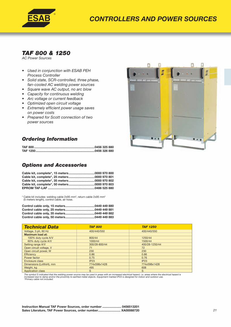
TAF 800 & 1250AC Power Sources
• Used in conjunction with ESAB PEHProcess Controller
• Solid state, SCR-controlled, three phase,fan-cooled AC welding power sources
• Square wave AC output, no arc blow• Capacity for continuous welding• Arc voltage or current feedback• Optimized open circuit voltage• Extremely effi cient power usage saves
on power costs• Prepared for Scott connection of two
power sources
Ordering Information TAF 800 ......................................................................0456 325 880TAF 1250 ....................................................................0456 326 880
Instruction Manual TAF Power Sources, order number ...................... 0456513201Sales Literature, TAF Power Sources, order number .......................... XA00088720
CONTROLLERS AND POWER SOURCES
Technical Data TAF 800 TAF 1250Voltage, 3 ph, 60 Hz 400/440/550 400/440/550Maximum load at:
100% duty cycle A/V 800/44 1250/4460% duty cycle A/V 1000/44 1500/44
Setting range A/V 300/28-800/44 400/28-1250/44Open circuit voltage, V 71 72Open circuit power, W 230 230Effi ciency 0.86 0.86Power factor 0.75 0.76Enclosure class IP23 IP23Dimensions (LxWxH), mm 774x598x1428 774x598x1428 Weight, kg 495 608 Application class S SThe symbol S indicated that the welding power source may be used in areas with an increased electrical hazard, i.e. areas where the electrical hazard is increased due to damp and/or the proximity to earthed metal objects. Equipment marked IP23 is designed for indoor and outdoor use.*Primary cable not included.
Options and AccessoriesCable kit, complete*, 15 meters ..............................0000 970 800Cable kit, complete*, 25 meters ..............................0000 970 801Cable kit, complete*, 35 meters ..............................0000 970 802Cable kit, complete*, 50 meters ..............................0000 970 803EPROM TAF-LAF ......................................................0486 525 880
* Cable kit includes: welding cable 2x95 mm2, return cable 2x95 mm2
(5 meters length), control cable, air hose.
Control cable only, 15 meters ..................................0449 449 880Control cable only, 25 meters ..................................0449 449 881Control cable only, 35 meters ..................................0449 449 882Control cable only, 50 meters ..................................0449 449 883

22
A2S Mini MasterA multi-purpose automatic welding system
Ordering InformationMIG System (A2)A2S GMAW MTW w/Manual Slides 90x90 mm .............................. 0449 181 880A2S GMAW MTW w/Motorized Slides 180x180 mm & PAK ........... 0449 181 881A2S GMAW MTW w/Motorized Slides 180x180 mm & GMD ......... 0449 181 882- Includes the PEH and Wire EquipmentSAW Systems (A2)A2S SAW w/Manual Slides 90x90 mm ........................................... 0449 170 880A2S SAW w/Motorized Slides 180x180 mm & PAK ........................ 0449 170 881A2S SAW w/Motorized Slides 180x180 mm & GMD ...................... 0449 170 882- Includes the PEH, Flux and Wire Equipment
Options and AccessoriesPilot lamp, light bulb ............................................... 0153 143 885Pilot lamp, laser diode ............................................ 0457 788 884Thin wire straightener, single wire ........................ 0332 565 880Flux recovery unit OPC ........................................... 0148 140 880Flux Hopper, 6 l ....................................................... 0413 315 881Concentric fl ux funnel ............................................ 0145 221 881Contact tube, bent .................................................. 0413 511 001Wire reel plastic 30 kg ............................................ 0153 872 880Wire reel steel 30 kg ............................................... 0416 492 880Conversion kit MIG/MAG ........................................ 0413 526 881Circular slide A6....................................................... 0671 171 580Manual slide A6 210 mm ..........................................0154 465 881Insulator A2-A6 ........................................................ 0278 300 180
• Versatile welding system for single wire SAW,twin wire SAW or GMAW
• Low weight and compact design allows forgreater fl exibility
• Modular design allows user to expand, integrate,or modify system quickly and easily
• Uses A2-A6 process controller PEH(see page 19 for more information)
• Accurate, easy joint-tracking with manual ormotorized slide system (see page 34 for moreinformation on joint-tracking)
• System attaches to any beam travelling carriageor Column & Boom system
WELDING HEADS
Instruction Manual A2S Mini Master, order number ....................0449175060Sales Literature A2S Mini Master, order number ........................XA00088820
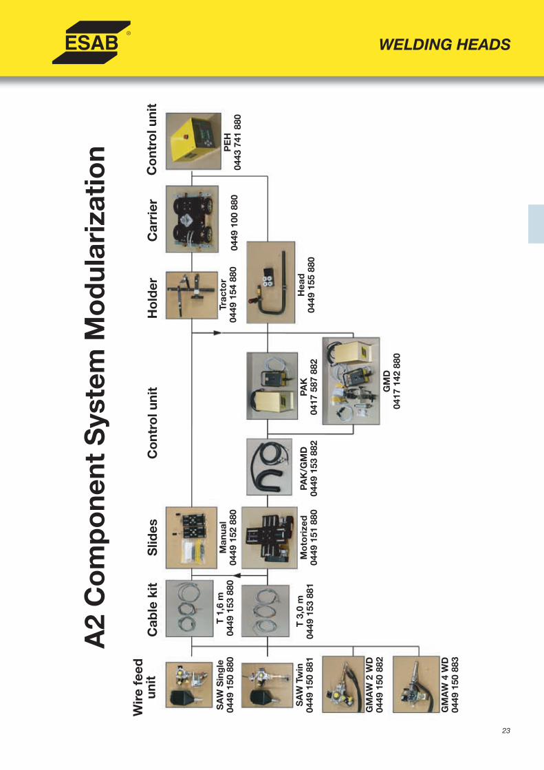
23
WELDING HEADS
A2
Co
mp
one
nt S
yste
m M
od
ular
izat
ion
Wir
e fe
ed
unit
Cab
le k
itS
lides
Co
ntro
l uni
tH
old
erC
arri
erC
ont
rol u
nit
SA
W S
ing
le04
49 1
50 8
80
SA
W T
win
0449
150
881
GM
AW
2 W
D04
49 1
50 8
82
GM
AW
4 W
D04
49 1
50 8
83
T 1
,6 m
0449
153
880
T 3
,0 m
0449
153
881
Man
ual
0449
152
880
Mo
tori
zed
0449
151
880
PAK
/GM
D04
49 1
53 8
82PA
K04
17 5
87 8
82
GM
D04
17 1
42 8
80
Trac
tor
0449
154
880
0449
100
880
Hea
d04
49 1
55 8
80
PE
H04
43 7
41 8
80

24
Ordering Information Single wire SAW system A6A6S SAW w/Manual Slides 210x210 mm – 156:1 ........................... 0449 270 880A6S SAW w/Motorized Slides 300x300 mm & PAK – 156:1 ........... 0449 270 881A6S SAW w/Motorized Slides 300x300 mm & GMD – 156:1 .......... 0449 270 882A6S SAW w/Manual Slides 210x210 mm – 74:1 ............................. 0449 270 890A6S SAW w/Motorized Slides 300x300 mm & PAK – 74:1 ............. 0449 270 891A6S SAW w/Motorized Slides 300x300 mm & GMD – 74:1 ............ 0449 270 892- Twin wire SAW available- Accessories: see page 12
• Flexibility, reliability, and superior performance capability • Comprehensive component and module system make
process customization easy• A6 VEC motor for reliable and consistent wire feed• Accurate, easy joint-tracking with manual slides or joystick-
controlled motor-operated cross slides(see page 34 for more information on joint-tracking)
• Capable of heavy duty MIG, single/twin wire SAW,as well as strip cladding and Synergic Cold Wire (SCW)welding with optional accessories
• Uses PEH process controller - fast, accurate pre-setting of all parameters before welding commences
• Feedback system ensures high and consistent weldingquality - save time and material
A6S Arc MasterFlexible, complete solution for automated arc welding
WELDING HEADS
Instruction Manual A6S Arc Master, order number ..................... 0449275060Sales Literature A6S Arc Master, order number .......................... XA00088920
Technical DataWelding current and wire dimensionsSubmerged arc welding DC or AC max 1500 AA6 feed unit (High Speed) (74:1)Wire feed speed, m/min 0.4-8Wire, single, mm 1.6-4.0Wire, twin, mm 2x1.2-2x2.5Cored wire, single, mm 1.6-4.0A6 feed unit (Low Speed 156:1)Wire feed speed, m/min 0.2-4.0Wire, single, mm 3.0-6.0Wire, twin, mm 2x2.0-2x3.0Cored wire, single, mm 3.0-4.0
Types of jointsButt and vertical or horizontal fi llet welds
Wire reelsOptional steel or plastic wire reel attached to welding head (To be order separately) Max 30 kg (wire or strip)
Flux hopperStandard type volume, l (gal) 10
Positioning, angularCircular slide, crank operated ± 180 °Straightener ± 45 °
Weights, kgFeed unit excluding slide, fl ux and wire equipment, and PEH 16Basic version, manual slides 64Basic version, motor operated cross slide with joystick control 80Basic version, with GMD 108
Operating voltage 42 V, 50/60 Hz

25
WELDING HEADS
A6
Co
mp
one
nt S
yste
m M
od
ular
izat
ion
Wir
e fe
ed
unit
Cab
le k
itS
lides
Co
ntro
l uni
tH
old
erC
arri
erC
ont
rol u
nit
Sin
gle
0449
250
880
Twin
0449
250
881
Sin
gle
Hig
h-sp
eed
0449
250
890
Twin
Hig
h-sp
eed
0449
250
891
T 1
,6 m
0449
253
880
S 3
,0 m
0449
253
881
Man
ual T
0449
252
880
Mo
tori
zed
0449
251
884
GM
D04
17 1
42 8
80
PAK
0417
587
882
PAK
/GM
D C
able
s04
49 1
53 8
82
Trac
tor
0449
254
880
0449
200
880
Hea
d (M
oto
rize
d)
0449
255
880
PE
H04
43 7
41 8
80
Man
ual S
0449
252
881
Hea
d04
49 2
55 8
81
26
WELDING HEADS
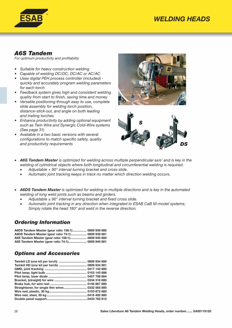
A6S TandemFor optimum productivity and profi tability
• Suitable for heavy construction welding• Capable of welding DC/DC, DC/AC or AC/AC • Uses digital PEH process controller (included) -
quickly and accurately program welding parameters for each torch
• Feedback system gives high and consistent welding quality from start to fi nish, saving time and money
• Versatile positioning through easy to use, complete slide assembly for welding torch position,distance-stick-out, and angle on both leadingand trailing torches
• Enhance productivity by adding optional equipment such as Twin Wire and Synergic Cold-Wire systems (See page 31)
• Available in a two basic versions with severalconfi gurations to match specifi c safety, qualityand productivity requirements
• A6S Tandem Master is optimized for welding across multiple perpendicular axis’ and is key in thewelding of cylindrical objects where both longitudinal and circumferential welding is required.
• Adjustable + 90° interval turning bracket and cross slide.• Automatic joint tracking keeps in track no matter which direction welding occurs.
• A6DS Tandem Master is optimized for welding in multiple directions and is key in the automatedwelding of long weld joints such as beams and girders.• Adjustable ± 90° interval turning bracket and fi xed cross slide.• Automatic joint tracking in any direction when integrated to ESAB CaB M-model systems; Simply rotate the head 180° and weld in the reverse direction.
Ordering Information A6DS Tandem Master (gear ratio 156:1) ................ 0809 939 880A6DS Tandem Master (gear ratio 74:1) .................. 0809 939 881A6S Tandem Master (gear ratio 156:1)................... 0809 940 880A6S Tandem Master (gear ratio 74:1)..................... 0809 940 881
Options and Accessories Twinkit LD (one kit per torch) ................................ 0809 934 880Twinkit HD (one kit per torch) ................................ 0809 934 881GMD, joint tracking ................................................ 0417 142 880Pilot lamp, light bulb ............................................... 0153 143 886Pilot lamp, laser diode ............................................ 0457 788 884Bracket, (straight) for wire ..................................... 0334 318 880Brake hub, for wire reel .......................................... 0146 967 880Straightener, for single thin wires .......................... 0332 565 880Wire reel, plastic, 30 kg ........................................... 0153 872 880Wire reel, steel, 30 kg ...............................................0416 492 880Double panel support ...............................................0433 762 812
Sales Literature A6 Tandem Welding Heads, order number ....... XA00119120
S
DS
27
WELDING HEADS
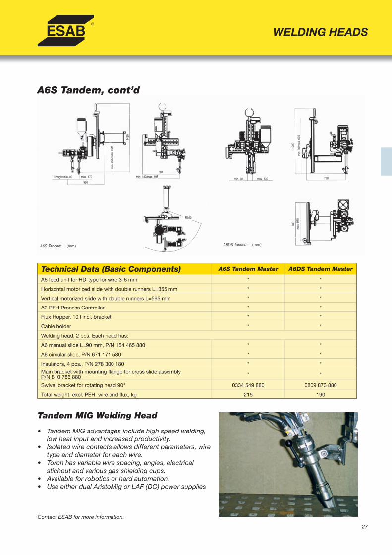
A6S Tandem, cont’d
Technical Data (Basic Components) A6S Tandem Master A6DS Tandem Master
A6 feed unit for HD-type for wire 3-6 mm * *
Horizontal motorized slide with double runners L=355 mm * *
Vertical motorized slide with double runners L=595 mm * *
A2 PEH Process Controller * *
Flux Hopper, 10 l incl. bracket * *
Cable holder * *
Welding head, 2 pcs. Each head has:
A6 manual slide L=90 mm, P/N 154 465 880 * *
A6 circular slide, P/N 671 171 580 * *
Insulators, 4 pcs., P/N 278 300 180 * *
Main bracket with mounting fl ange for cross slide assembly,P/N 810 786 880 * *
Swivel bracket for rotating head 90° 0334 549 880 0809 873 880
Total weight, excl. PEH, wire and fl ux, kg 215 190
Tandem MIG Welding Head
• Tandem MIG advantages include high speed welding, low heat input and increased productivity.
• Isolated wire contacts allows different parameters, wire type and diameter for each wire.
• Torch has variable wire spacing, angles, electricalstichout and various gas shielding cups.
• Available for robotics or hard automation.• Use either dual AristoMig or LAF (DC) power supplies
Contact ESAB for more information.

28
WELDING HEADS
A6S Compact Welding Heads for Internal Tube Welding
• For welding longitudinal and circumferential buttjoints inside tubes
• Two versions available: • A6S Compact 300 for internal welding of tubes
down to 300 mm inside diameter • A6S Compact 500 for internal welding of tubes
down to 500 mm inside diameter• Supervise and adjust the head position via TV
monitoring system• Use standard mini-cross slide assembly and PAK ma-
nual tracking system or GMD automatic joint tracking system to easily follow the joint
• Add either the FFRS Basic/Super o FFRS 1200/3000 Flux Feed & Recovery System to optimize the welding process
Ordering Information A6S Compact 300 Welding Head, standard .......0809 280 880A6S Compact 300 Welding Head, high-speed ...0809 280 881A6S Compact Welding Head 500* .......................0416 967 880* Contact ESAB for Ordering Information, Options & Accessories and
Technical Data A6S Compact 500 Welding Heads.
Options & Accessories Flux valve control Kit ............................................0813 620 880Include solenoid valve and 5 m air hoseInductive Sensor ...................................................0811 178 880TV Monitoring Equipment ....................................0811 176 880Laser Pointer .........................................................0811 177 880
Contact Tips, wire sizeM12, 3,0 mm ..........................................................0154 623 005M12, 3,5 mm ..........................................................0154 623 004M12, 4,0 mm ..........................................................0154 623 003
Feed Rollers, wire size3,0 – 3,2 mm ..........................................................0218 510 2983,0 mm ...................................................................0218 510 286
Technical Data
Wire Dimensions, mmSteel 3,0 - 4,0
Stainless Steel 3,2
Permissible Load 100%, A 800
Contro Voltage, VAC 42
Travel Speed, cm/min 10 - 170
Linear Slides Setting Range, mm 50
Angular Slide Setting Range 360°
Wire Feed Speed, standard, cm/min 20 - 400
Wire Speed Feed, high-speed, cm/min 40 - 800
ESAB A6S Compact 300 Sales Literature, order number ................................ XA00124620
A6S Compact 300 Welding Head
A6S Compact 500 Welding Head

29
WELDING HEADS
A6S SAW Strip Cladding Head
Ordering Information SAW Strip Cladding Kit ...........................................0155 972 880Flux suction nozzle ...................................................0156 025 001ESW Strip Cladding Kit 30-40 ..................................0772 306 880ESW Strip Cladding Kit 60-90 ..................................0772 385 880Magnetic Deviator ...................................................0772 285 880For use with A6S SAW tractor or A6S Arc Master head
Options and Accessories Reel holder ...............................................................0417 636 880Not to be used with motor-operated cross slideWire reel, steel ..........................................................0416 492 880
• Used in combination with standard A6S Arc Master welding head
• Provides an economical solution for surfacing with high alloyed materials such as stainless steel ornickel-based alloys
• Choose a wider variety of parent materials andconsumables
• Stainless steel cladding is widely used in production of components where additional strength orcorrosion resistance is required
• Welding head can be fi tted with electrode strips as wide as 30-100 mm and as thick as 0,5 mm
• Recommended for use with LAF 1250 or LAF 1600 power sources and PEH process controller(see pages 20-21)
Sales literature A6S Strip Cladding Head, order number .................. XA00101020
Technical Data Strip Torch ESW 30-60 Torch ESW 60-90 TorchCurrent capacity, A 1500 max 2000 max 2500 maxFeed roll diameter, mm 50 50 50Strip width, mm 30-100 30-60 60-90Strip thickness, mm 0,5 0,5 0,5
A6S ESW Strip Cladding Head(Electroslag)
• For strips as wide as 30-60 mm• Up to 2000 A, water cooled
(Cooling unit available on request)• Magnetic deviator• Kit including VEC motor + 1-liter fl ux tank

30
• Automatic welding equipment for SAW welding of manholes on cylindrical objects or plates
• For manholes having external diameter from 300 to 1100 mm
• Available with tilting device for thesynchronization with roller beds
• Rotating collector for signal, power andcompressed air transmission, to make it possible an “infi nite” rotation without the need to rewind cables
• PEH panel available on request
Ordering InformationMHW ........................................................................ 0000 960 271MHW with balancing device ................................... 0000 960 272
Sales literature MHW welding head, order number ............................... 0073332201949
WELDING HEADS
Automatic Welding Head for Manholes - PEG1 / PEH
Technical DataCurrent capacity, A 1500Max external diameter, mm 1100Min internal diameter, mm 200*Manhole height, mm 150 (under-collar) - 750Clamping min. height, mm 25
* If wall thickness of manhole is 50 mm, the min diameter can be of 150 mm

31
WELDING HEADS
Synergic Cold Wire Kit ComponentsMotor VEC (156:1) .................................................... 0145 063 886Straightener left ....................................................... 0147 639 881Breake hub ............................................................... 0146 967 880Braket A6 .................................................................. 0154 734 001Cartridge A6 ............................................................. 0156 907 001Hand-wheel isolated A6 .......................................... 0218 810 183
Options and AccessoriesContact Device, L=400mm (D35) ............................ 0417 959 882Wire reel, steel ......................................................... 0416 492 880Twin-wire Kit ............................................................ 0334 291 88906A - Iron powder batching device ........................ 0413 630 880
• Increase productivity by boosting deposition rate by up to 50% for any given current/wire feed speed (utilizes excess heat from arc)
• Synergic Cold Wire welding offers lessdistortion, reduced fl ux consumption, and fewer weld beads
• Easy to use, requires no additional control units or separate wire feed mechanisms
• Allows fl exible process confi guration- solid/cored wires, single, twin wire, tandem andmultiple wire combinations
• Synergic Cold Wire has no arc and can be used for “hard to weld” alloys with cored wire
• Set wire in leading or trailing position depending on requirement of penetration vs. build-up
• Fits all ESAB A6 systems
Ordering InformationSynergic Cold Wire Kit, complete ......................... 0449 022 880Includes VEC Motor (156:1), straightener (left),breake hub, cartridge, hand-wheel and mounting hardware
Sales Literature A6 Synergic cold wire, order number ............................... XA00094920
A6 Synergic Cold Wire

32
ACCESSORY COMPONENTS
Ordering Information Beam Travelling carriage ....................................... 0457 897 880
Options and Accessories Mounting bracket for Tandem head ..................... 0458 026 001Track in lengths of 3 m ........................................... 0145 282 880 Required number of fl oor columns: 2Track in lengths of 4,5 m ........................................ 0145 282 881 Required number of fl oor columns: 3Track in lengths of 6,0 m ......................................... 0145 282 882 Required number of fl oor columns: 3 Track in lengths of 8,0 m ........................................ 0145 282 883 Required number of fl oor columns: 4
A6B Beam Travelling Carriage
• Ideal solution for submerged-arc and MIG/MAG welding applications requiring beam-mounted carriage
• Can be fi tted with any A2 or A6 welding head• Place carriage on either a standard l-beam
IPE 300 or specially machined l-beam(contact ESAB for details)
• Fast and easy pre-programming of travel motion and welding parameters using PEH control(To be ordered separately)
Instruction Manual A6B Beam Travelling Carriage, order number ............... 0458028001Sales Literature A6B Beam Travelling Carriage, order number .................... XA00091920
Technical DataTravel speed Beam-carriage, cm / min 6-200Carriage weight (head not included), kg 60

33
ACCESSORY COMPONENTS
Motorized slidesServo slides for automated linear motion
• Heavy duty capacity with high precision slide for accurate and rapid joint tracking and positioning
• Can be installed in vertical or horizontalpositions- setting lengths up to 1.030 mm with a central point of attachment
• Operates jointly with A2 or A6 components• Slides available from 60 mm to 1.030 mm
working range• Permissible load of 1500 N in any mounting
position• Maximum torque for vertical unit is 400Nm;
maximum torque for horizontal unit is 280 Nm.
Instruction Manual Motorized Slides, order number . 0443394060Sales Literature Motorized Slides, order number .... XA00032720
Connection CablesOne connection cable is required for each servo slide for connection of slide to linear motion controller (eg. GMD or PAK)Connection cable, 2 mt .......................................... 0417 310 887Connection cable, 5 mt .......................................... 0417 310 888Connection cable, 10 mt ........................................ 0417 310 889
Ordering Information
Servo Slide 0334 333 -880 -881 -882 -883 -884 -885 -886 -887 -888Setting length, mm 60 120 180 240 300 420 540 730 1030Total length, mm 305 365 425 485 545 665 785 1025 1385Number of 60 mm Indexings 3 4 5 6 7 9 11 14 21Weight, kg 11,5 13,2 15 16,7 18,5 21,9 25,4 30,9 38,8Order connection cables separatly
Technical DataControl voltage, VDC 42Max ambient temperature, °C 80Axial play runner, mm 0,1Max Torque-free load, kg 150

34
ACCESSORY COMPONENTS
PAK and GMD – Joint Positioning and Tracking SystemsThe key to quality in automated welding
• Simple and easy to use• Adapt for use with almost any type of welding
joint • PAK system is for manual joint tracking;
GMD system is for automatic joint tracking• PAK and GMD work equally well with A2
or A6 welding systems• Motorized servo slides guarantee a reliable
and accurate joint tracking • PAK system available with or without remote
control, and can be integrated into a Column and Boom welding system
• GMD automatic joint tracking system isdesigned for use in fi llet and butt joints using sensor fi ngers
• GMD compensates for irregularities in weld joint, tracks simple geometric shapes, andavoids parallax problems
• Standard GMD components include: sensor with fi nger, cross saddle and support for sensor, GMD joint tracking unit, GMD remote control unit with a 3.5 m cable, and control cable 2 m for connecting the control unit with the sensor
Ordering InformationGMD system, complete ............................................................................... 0417 142 880
PAK Control Unit, joy-stick on front panel .................................................. 0417 587 880PAK Control Unit, separate remote control ................................................ 0417 587 882PAG Manual control unit ............................................................................... 0156 405 881
Includes GMD joint tracking unit, GMD remote control with 3.5 m cable, 2 m control cable, sensor with fi nger, and cross saddle and support for sensor
Instruction Manual Joint Tracking System (GMD), order number ..... 0443403002Instruction Manual Joint Tracking System (PAK), order number ....... 0443405002Sales Literature Joint Tracking System (GMD/PAK), order number .. XA00068420
Option and Accessories* Sensor with fi nger .................................................... 0416 688 880Cross saddle and support for the sensor .............. 0416 739 880GMD joint tracking unit ............................................ 0416 066 880GMD remote control unit ......................................... 0416 065 880Control cable 2m ...................................................... 0416 749 887Finger with ball ......................................................... 0416 719 001Protective rubber boot ............................................. 0412 013 001Finger for beam welding .......................................... 0443 187 880Standard fi nger ......................................................... 0146 586 001Intermediate transformer ........................................ 0148 636 002
*Only for GMD models

35
ACCESSORY COMPONENTS
PAK and GMD – Joint Positioning and Tracking Systems (Cont’d)The key to quality in automated welding
Technical DataPAK Control UnitControl and operating voltage 42V AC 50-60 HZPower requirement 460 VAEnclosure type IP 23Max ambient temperature, °C +45°Weight, kg 4.5Weight remote control unit, kg 2.0
GMD Sensor with fi ngerSensitivity, mm +/-0.1Weight sensor, kg 0.6
Cross saddle and support for the sensorCross saddle, setting length, mm 80Weight cross saddle, kg 1.6
GMD Joint tracking unitControl and operating voltage 42V AC 50-60 HZPower requirement 460 VAEnclosure type IP 53Max ambient temperature, °C ° +45°Weight, kg 2.2
GMD remote control unitPositioning speed: High / LowWeight, kg 2.0
GMD AccessoriesFinger with ball, Length, mm 100Intermediate Transformer, for separate voltage supply 200/230/440/500V 60 Hz Main to 42V secondary

36
ACCESSORY COMPONENTS
• Robust and compact design• Easy to operate and practically
maintenance-free • Integrated system for maximum productivity-
lower investment and service costs• Adapts to any A2 or A6 welding
system- tractor or stationary• Uses only compressed air- safe and
inexpensive to use• Can be integrated into complete FFRS fl ux
feeding and recovery system• Three fi lter types: Filter bag for A2 applications,
cyclone fi lter with fi lter bag for mostA6 applications, and Tedak fi lter for heavy duty applications
• OPC system includes: Ejector, cyclone, fi lter with attachment hardware, securing strap, suction hose, and four suction nozzles (for butt welds, normal and large; fi llet welds, left and right)
Ordering Information OPC Basic, with standard fi lter bag ...................... 0148 140 880OPC Basic, with cyclone fi lter ................................ 0802 415 882OPC Basic, with Tedak fi lter ................................... 0802 415 883OPC Super, with cyclone fi lter ............................... 0802 415 892OPC Super, with Tedak fi lter ................................... 0802 415 893Powder separation fi lter ..........................................0000 908 997
Powder separation tank ...........................................0000 970 361OPC fi lter bag ...........................................................0155 966 001Powder collecting tube ............................................0000 909 234Pneumatic valve .......................................................0254 901 181Electro-valve .............................................................0000 970 137Hopper .......................................................................0147 649 881
Instruction Manual OPC Flux Recovery System, order number ................. 0443407001Sales Literature OPC Flux Recovery System, order number ....................... XA00105020
• Works on ejector principle using compressed air• Cyclone separator, on top of fl ux hopper,
effi ciently separates dust from recovered fl ux• Slag is separated and fl ux is returned to hopper
OPC Basic Flux Recovery System
OPC Super Flux Recovery System
• Similar to Basic system but with stronger ejectorand cyclone – provides better suction
• Can also be used with pre-heated fl ux
OPC – Flux Recovery SystemsRobust, compact fl ux recovery units
1 - Air pressure hose, 3/8”2 - Air pressure hose, 1/2”3 - Air pressure tube, 63 mm4 - Air central5 - Plastic bag6 - Filter bag7 - Filter bag, cyclone, tedak
OPC Basic OPC Basic/Super with cyclone fi lter
Tedak Filter
37
ACCESSORY COMPONENTS
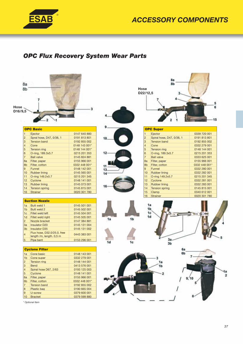
OPC Flux Recovery System Wear Parts
OPC Basic1 Ejector 0147 640 8802 Spral hose, D47, 0/38, 1 0191 813 8013 Tension band 0192 855 0024 Cone 0148 143 001*5 Tension ring 0148 144 001*6 O-ring, 189.3x5.7 0215 201 3537 Ball valve 0145 824 8818a Filter, paper 0155 966 0018b Filter, cotton 0332 448 001*9 Funnel 0148 142 00110 Rubber lining 0145 565 00111 O-ring 149.2x5.7 0215 201 34512 Cyclone 0148 141 00113 Rubber lining 0145 073 00114 Tension spring 0145 815 00116 Strainer 0020 301 780
Suction Nozzle1a Butt weld 1 0145 501 0011b Butt weld 2 0145 502 0011c Fillet weld left 0145 504 0011d Fillet weld right 0145 505 0012 Nozzle bracket 0147 384 8813a Insulator D20 0145 131 0043b Insulator D35 0145 131 002
4Flux hose, D32.0/25.0, free length /m, length. 0,5 m
0443 383 001
5 Pipe bent 0153 296 001
Cyclone Filter1a Cone basic 0148 143 0011b Cone super 0332 279 0012 Tension ring 0148 144 0013 Bend 0413 576 0014 Spiral hose D67, 2/63 0193 125 0035 Cyclone 0148 141 0016a Filter, paper 0155 966 0016b Filter, cotton 0332 448 001*7 Tension band 0192 855 0028 Plastic bag 0190 665 0049 U-screw 0379 600 00110 Bracket 0379 599 880
OPC Super1 Ejector 0339 720 0012 Spiral hose, D47, 0/38, 1 0191 813 8013 Tension band 0192 855 0024 Cone 0332 279 0015 Tension ring 0148 144 0016 O-ring, 189.3x5.7 0215 201 3537 Ball valve 0333 625 0018a Filter, paper 0155 966 0018b Filter, cotton 0332 448 001*9 Funnel 0332 280 00110 Rubber lining 0332 282 00111 O-ring 149.2x5.7 0215 201 34512 Cyclone 0332 281 00113 Rubber lining 0332 283 00114 Tension spring 0145 815 00115 Clamp 0340 612 00116 Strainer 0020 301 780
HoseD16/9,5
HoseD22/12,5
* Optional Item
38
Options and AccessoriesAir center .................................................................. 0417 714 880TPC armoured tube ................................................. 0000 970 061Suction hose D47/38 (max 12 m)........................... 0379 016 001Flux hopper with bent inlet pipe 10 lleft hand side seen from front ............................... 0156 230 883Flux hopper with bent inlet pipe 6 lleft hand side seen from front ................................ 0413 404 883Low level indicator TPC-75 fl ux tank .................... 0452 048 880Pre-heating kit for 10 l fl ux hopper .........................0000 970 374
Ordering Information
FFRS 3000 systems consist of TPC-75 fl ux pressure tank, motor driven vacuum unit with dust fi lter, common mounting post for system, air pressure regula-tor with water trap, suction hose between primary separator and vacuum unit, air central with 10 m air hose included, fl ux suction nozzle, and fl ux feeding hose 30 m included.
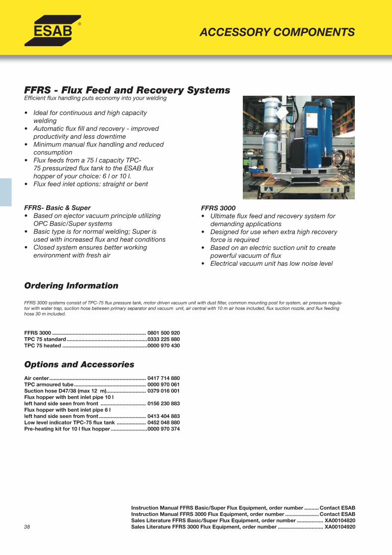
FFRS - Flux Feed and Recovery SystemsEffi cient fl ux handling puts economy into your welding
• Ideal for continuous and high capacitywelding
• Automatic fl ux fi ll and recovery - improved productivity and less downtime
• Minimum manual fl ux handling and reduced consumption
• Flux feeds from a 75 l capacity TPC- 75 pressurized fl ux tank to the ESAB fl ux hopper of your choice: 6 l or 10 l. • Flux feed inlet options: straight or bent
FFRS- Basic & Super• Based on ejector vacuum principle utilizing
OPC Basic/Super systems• Basic type is for normal welding; Super is
used with increased fl ux and heat conditions• Closed system ensures better working
environment with fresh air
FFRS 3000 ................................................................ 0801 500 920TPC 75 standard .......................................................0333 225 880TPC 75 heated ..........................................................0000 970 430
FFRS 3000• Ultimate fl ux feed and recovery system for
demanding applications• Designed for use when extra high recovery
force is required • Based on an electric suction unit to create
powerful vacuum of fl ux • Electrical vacuum unit has low noise level
Instruction Manual FFRS Basic/Super Flux Equipment, order number .......... Contact ESABInstruction Manual FFRS 3000 Flux Equipment, order number ....................... Contact ESABSales Literature FFRS Basic/Super Flux Equipment, order number .................. XA00104820Sales Literature FFRS 3000 Flux Equipment, order number ............................... XA00104920
ACCESSORY COMPONENTS
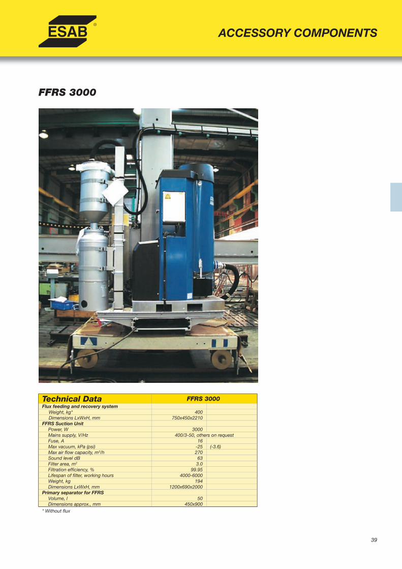
39
FFRS 3000
ACCESSORY COMPONENTS
Technical Data FFRS 3000Flux feeding and recovery system Weight, kg* 400 Dimensions LxWxH, mm 750x450x2210FFRS Suction Unit
Power, W 3000Mains supply, V/Hz 400/3-50, others on requestFuse, A 16Max vacuum, kPa (psi) -25 (-3.6)Max air fl ow capacity, m3/h 270Sound level dB 63Filter area, m2 3.0Filtration effi ciency, % 99.95Lifespan of fi lter, working hours 4000-6000Weight, kg 194Dimensions LxWxH, mm 1200x690x2000
Primary separator for FFRSVolume, l 50Dimensions approx., mm 450x900
* Without fl ux

40
CRE 30 & CRE 60 Air Drying Units
ACCESSORY COMPONENTS
• Designed for use with any fl ux handling system• System is based on absorption principle -
reduces the risk of hydrogen cracking in weld metal by ensuring SAW fl ux remains dry
• Built in monitor- warns if the programmedhumidity limit is exceeded
• Reduces condensation- less corrosion andmalfunctions
• Simple system monitoring- Manometer on pressurized dryer bottles with easy-to-read dew point indicator
Ordering Information CRE 30 air drying unit ............................................. 0443 570 880CRE 60 air drying unit ............................................. 0443 570 881
Instruction Manual CRE 30/60 Air Dryer, order number ...... 0443423001Sales Literature CRE 30/60 Air Dryer, order number ........... XA00101920
Technical Data CRE 30 CRE 60Supply voltage (AC) 230 V 50/60 Hz 230 V 50/60 HzMax power rating 40W 50WNet air fl ow capacity at 6 bar, m3/h 30 60Regenerating fl ow at 6 bar 14% 14%Max dew point under nominal working conditions -26 -26Desiccant, Type 512
Sodium-Aluminum-Silicate, kg 10 16Normal pore size, Angstrom 4 4Particle size, mm 2,5-5,0 2,5-5,0Density, kg/m3 720 720
Cycle time per container 5000-6000 4000-6000Max permissable air fl ow for oil separation fi lter, m3/h 60 60Mainfold thread size R12” R12”Max working pressure, bar 6 6Max air pressure at testing, bar 10 10Max inlet air temp, under nominal conditions, °C 30 30

41
ACCESSORY COMPONENTS
Ordering InformationIncludes camera, camera housing, monitor, crosshair generator, camera mounting bracket,work light, work light bracket, necessary cables.
A2/A6 SAW camera system with cooling unit ............................. 0811 412 880A2/A6 SAW camera system without cooling unit ....................... 0811 412 881
SAW compact camera system with cooling unit ........................ 0811 413 900SAW compact camera system without cooling unit .................. 0811 413 901
GMAW camera system with cooling unit .................................... 0811 414 880GMAW camera system without cooling unit ............................... 0811 414 881
Overview SAW camera system without cooling unit ................. 0811 413 881SAW compact basic camera system with cooling unit.............. 0811 413 880SAW compact basic camera system without cooling unit ........ 0811 413 882
Camera Systems for Submerged and Open Arc Welding
• Together with a laser or pilot lamp, control the welding process from a convenient location.
• System consists of a purposeful designed camera with built-in crosshair generator to provide a continuous and distinct joint scanning
• In combination with the 15 in. fl at screen, it becomes a unit for excellent control and joint tracking.
• Upon welding, the camera switches over to viewing the pool, facilitating the supervision of the process.
• Optional overwiew camera will reproduce a picture of the welded joint to get an immediate inspection of the welding quality.
Technical Data SAW Camera GMAW/SAW CompactCamera
Overview/SAW CompactBasic Camera
TV Standard PAL / NTSC PAL / NTSC PAL / NTSC
Model No. VUP2.01P/VUP2.01N WeldCam/SAWC OV3.04
Resolution 480TVL 480TVL 350 TVL
Min. illumination 0.25 lx (con F1.6) ---- 3.0 lx
Electronic Iris Autom.1/60 (1/50) - 1/10000 sec Autom.1/50 - 1/10000 sec 1/50-1/10000 sec
Horizontal fi eld angleapprox 79°,focale 3,5mm (Wide)approx 33°,focale 8 mm (Tele)
---- ----
Vertical fi eld angleapprox 63°,focale 3,5mm (Wide)approx 25°,focale 8 mm (Tele)
---- ----
Focal length varifocal lens, 3,5mm – 8mm ---- ----
External terminalsA-power input +12VDC, B-GND
C-video output, D-GND---- ----
Output resistance ---- 75 ohm ----
Power supply range DC 12V DC+/-0,5V DC+6V-DC+7,5V
Power consumption 200mA (max) 360mA (max) 200mA (max)
Temperature range -10°C - +50°C (PCB) -10°C - +50°C (PCB) ----
Dimensions, mm 60x60x105 145x24x24 18x18x43 +lens
Weigth, kg approx 0,46 approx 0,46 approx 0,025
Note: SAW compact basic and Overview camera have the same specifi cations, but SAW compact basic is used for compact applications. SAW compact basic is a simpler alternative to SAW compact camera.
Camera System Literature, order number ..................................... XA00124520
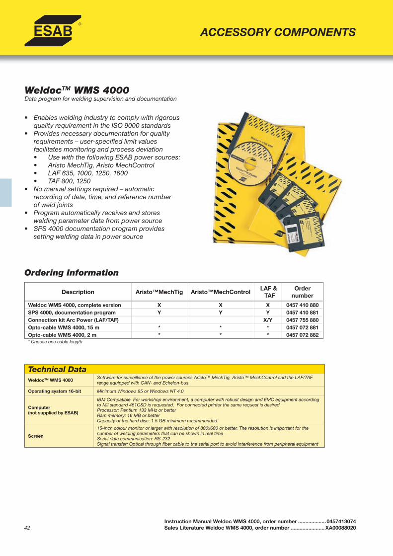
42
WeldocTM WMS 4000Data program for welding supervision and documentation
• Enables welding industry to comply with rigorous quality requirement in the ISO 9000 standards
• Provides necessary documentation for qualityrequirements – user-specifi ed limit valuesfacilitates monitoring and process deviation
• Use with the following ESAB power sources: • Aristo MechTig, Aristo MechControl • LAF 635, 1000, 1250, 1600 • TAF 800, 1250• No manual settings required – automatic
recording of date, time, and reference numberof weld joints
• Program automatically receives and storeswelding parameter data from power source
• SPS 4000 documentation program providessetting welding data in power source
Ordering Information
Instruction Manual Weldoc WMS 4000, order number ...................0457413074Sales Literature Weldoc WMS 4000, order number ....................... XA00088020
ACCESSORY COMPONENTS
Technical DataWeldocTM WMS 4000 Software for surveillance of the power sources Aristo™ MechTig, Aristo™ MechControl and the LAF/TAF
range equipped with CAN- and Echelon-bus
Operating system 16-bit Minimum Windows 95 or Windows NT 4.0
Computer(not supplied by ESAB)
IBM Compatible. For workshop environment, a computer with robust design and EMC equipment according to Mil standard 461C&D is requested. For connected printer the same request is desiredProcessor: Pentium 133 MHz or betterRam memory; 16 MB or betterCapacity of the hard disc: 1.5 GB minimum recommended
Screen
15-inch colour monitor or larger with resolution of 800x600 or better. The resolution is important for the number of welding parameters that can be shown in real timeSerial data communication: RS-232Signal transfer: Optical through fi ber cable to the serial port to avoid interference from peripheral equipment
Description Aristo™MechTig Aristo™MechControlLAF &
TAFOrder
number
Weldoc WMS 4000, complete version X X X 0457 410 880SPS 4000, documentation program Y Y Y 0457 410 881Connection kit Arc Power (LAF/TAF) X/Y 0457 755 880Opto-cable WMS 4000, 15 m * * * 0457 072 881Opto-cable WMS 4000, 2 m * * * 0457 072 882* Choose one cable length

43
Ordering Information
All Turning Rolls include RC-30 remote control with 12 m cable Power Section 5 TA ............... PH10356300Power Section 10 TA ............. PH10356400Power Section 25 TA ............. PH10356500Power Section 40 TA ............. PH10356601Power Section 70 TA ............. PH10356701Power Section 100 TA ........... PH10356800Power Section 150 TA ........... PH10356900Power Section 200 TA ........... PH10357001Power Section 300 TA ........... PH10357101Power Section 500 TA ........... PH10357201
5-500 TASelf-aligning Turning Rolls
• Ideal for diffi cult and demanding work pieces• Even weight distribution for thin-walled work
pieces and heavy objects• Compact and narrow design with durable rollers• Dual drive motors and gears- eliminate need for
interconnect driveshaft• Vector inverter control system for constant and
precise speed control• Equipped with RC-30 remote control with a
12 m cable • Plug & play connection to accessories available
including synchronization control, externalconnection, rail bogies, anti-creep/fi t-up control, start/stop foot pedal, and PEH process controller
Sales Literature TA Turning Rolls, order number ................ XA00120320
HANDLING EQUIPMENT
Idler Section 5 TA.................. PH10357300Idler Section 10 TA................ PH10357400Idler Section 25 TA................ PH10357500Idler Section 40 TA................ PH10357600Idler Section 70 TA................ PH10357700Idler Section 100 TA.............. PH10357800Idler Section 150 TA.............. PH10357900Idler Section 200 TA.............. PH10358000Idler Section 300 TA.............. PH10358101Idler Section 500 TA.............. PH10358201
Technical Data 5 TA 10 TA 25 TA 40 TA 70 TA 100 TA 150 TA 200 TA 300 TA 500 TA
Max load, metric ton 2.5 5.0 12.5 20 35 50 75 100 150 250
Rolling Capacity, metric ton 7.5 15 37.5 60 105 150 225 300 450 750
Max rotation force, kN 5.5 11 20 32 60 75 110 165 210 250
Rotation speed, mm/min 60-1250 60-1250 60-1250 60-1250 60-1250 60-1250 60-1250 60-1250 60-1250 60-1250
Diameter range 75 % loadmin-max, mm
500-4500 500-4500 500-4500 1000-5200 1000-5200 1000-7800 1000-7800 1000-7800 1000-7800 1000-7800
Diameter range 100 % load min-max, mm
1250-4500 1250-4500 1250-4500 1750-5200 1750-5200 2000/7800 2000/7800 2000/7800 2000/7800 2000/7800
Rollers pcs/section 4 4 8 4 8 4 8 8 8 4
Roller dia/total width, mm 350/75) 350/75 350/150 425/150 425/300 580/220 580/450 580/450 710/520 710/260
Roller material PU PU PU PU PU PU PU PU PU Acciaio
Length, mmPower 2560) 2625 2665 3070 3070 3750 3800 3800 4700 5500
Idler 2200 2200 2200 2710 2710 3450 3450 3450 4200 4400
Width, mmPower 720 720 775 1050 1230 1400 1900 2000 2200 2200
Idler 400 490 490 830 830 900 1300 1400 1400 1400
Weight, kgPower 760 925 1185 1770 2430 5000 6200 7000 12000 18000
Idler 585 585 751 1220 1670 4000 4500 5300 9000 15000
Primary Input Voltage, VAC, 60 Hz 230 1ph 460/575 3ph 460/575 3ph 460/575 3ph 460/575 3ph 460/575 3ph 460/575 3ph 460/575 3ph 460/575 3ph 460/575 3ph
Primary Input Current, A 16 16 16 16 16 16 16 16 16 16
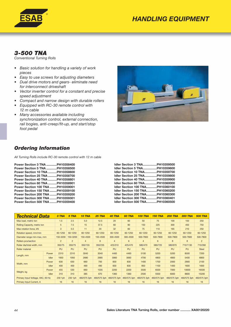
44
HANDLING EQUIPMENT
3-500 TNAConventional Turning Rolls
• Basic solution for handling a variety of workpieces
• Easy to use screws for adjusting diameters• Dual drive motors and gears- eliminate need
for interconnect driveshaft• Vector inverter control for a constant and precise
speed adjustment• Compact and narrow design with durable rollers• Equipped with RC-30 remote control with
12 m cable • Many accessories available including
synchronization control, external connection,rail bogies, anti-creep/fi t-up, and start/stopfoot pedal
Sales Literature TNA Turning Rolls, order number ............ XA00120220
Ordering Information
All Turning Rolls include RC-30 remote control with 12 m cable Power Section 3 TNA ............PH10358400Power Section 5 TNA ............PH10358500Power Section 10 TNA ..........PH10358600Power Section 25 TNA ..........PH10358700Power Section 40 TNA ..........PH10358801Power Section 60 TNA ..........PH10358901Power Section 100 TNA ........PH10359001Power Section 150 TNA ........PH10359100Power Section 200 TNA ........PH10359200Power Section 300 TNA ........PH10359301Power Section 500 TNA ........PH10359400
Idler Section 3 TNA ................PH10359500Idler Section 5 TNA ................PH10359600Idler Section 10 TNA ..............PH10359700Idler Section 25 TNA ..............PH10359800Idler Section 40 TNA ..............PH10359900Idler Section 60 TNA ..............PH10360000Idler Section 100 TNA ............PH10360100Idler Section 150 TNA ............PH10360200Idler Section 200 TNA ............PH10360300Idler Section 300 TNA ............PH10360401Idler Section 500 TNA ............PH10360500
Technical Data 3 TNA 5 TNA 10 TNA 25 TNA 40 TNA 60 TNA 100 TNA 150 TNA 200 TNA 300 TNA 500 TNA
Max load, metric ton 1.5 2.5 5.0 12.5 20 60 50 75 100 150 250
Rolling Capacity, metric ton 5 7.5 15 37.5 60 90 150 225 300 450 750
Max rotation force, kN 3 5.5 11 20 32 60 75 110 165 210 250
Rotation speed, mm/min 60-1250 60-1250 60-1250 60-1250 60-1250 60-1250 60-1250 60-1250 60-1250 60-1250 60-1250
Diameter range min-max, mm 150-3200 150-3200 150-4500 150-4500 300-4500 300-4500 500-7800 500-7800 500-7800 500-7800 500-7800
Rollers pcs/section 2 2 4 6 4 6 4 6 8 8 2
Roller dia/total width, mm 350/75 350/75 350/155 350/235 425/310 425/470 580/470 580/720 580/970 710/1130 710/260
Roller material PU PU PU PU PU PU PU PU PU PU Steel
Length, mmPower 2310 2310 3040 3040 4460 4460 5100 5200 5200 8500 7200
Idler 1950 1950 2680 2685 3060 3060 4700 4800 4800 5400 6800
Width, mmPower 630 630 660 700 830 830 1400 1700 2000 2900 2100
Idler 400 400 490 490 830 830 850 1100 1400 1600 1600
Weight, kgPower 455 530 660 1035 2200 2200 3500 6500 7000 10000 16500
Idler 310 310 385 670 1360 1360 2500 5500 6000 8800 15200
Primary Input Voltage, VAC, 60 Hz 230 1ph 230 1ph 460/575 3ph 460/575 3ph 460/575 3ph 460/575 3ph 460/575 3ph 460/575 3ph 460/575 3ph 460/575 3ph 460/575 3ph
Primary Input Current, A 16 16 16 16 16 16 16 16 16 16 16
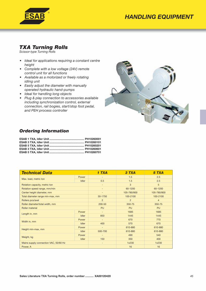
45
Ordering Information
ESAB 1 TXA, Idler Unit ............................................. PH10260001ESAB 3 TXA, Idler Unit ............................................. PH10260101ESAB 5 TXA, Idler Unit ............................................. PH10260201ESAB 3 TXA, Idler Unit ............................................. PH10260601ESAB 5 TXA, Idler Unit ............................................. PH10260701
TXA Turning RollsScissor-type Turning Rolls
• Ideal for applications requiring a constant centre height
• Complete with a low voltage (24V) remotecontrol unit for all functions
• Available as a motorized or freely rotatingidling unit
• Easily adjust the diameter with manuallyoperated hydraulic hand-pumps
• Ideal for handling long objects • Plug & play connection to accessories available
including synchronization control, externalconnection, rail bogies, start/stop foot pedal, and PEH process controller
Sales Literature TXA Turning Rolls, order number ........... XA00120420
HANDLING EQUIPMENT
Technical Data 1 TXA 3 TXA 5 TXA
Max. load, metric tonPower - 1.5 2.5
Idler 0.5 1.5 2.5
Rotation capacity, metric ton - 3 5
Rotation speed range, mm/min - 60-1200 60-1200
Center height diameter, mm - 105-780/800 105-780/800
Total diameter range min-max, mm 30-1750 100-2100 100-2100
Rollers pcs/axel 2 2 4
Roller diameter/total width, mm 200-50 350-75 350-75
Roller material PU PU PU
Length in, mmPower - 1685 1685
Idler 850 1445 1445
Width in, mmPower - 670 770
Idler 400 570 670
Height min-max, mmPower - 610-880 610-880
Idler 500-700 610-880 610-880
Weight, kgPower - 490 540
Idler 150 350 400
Mains supply connection VAC, 50/60 Hz - 1x230 1x230
Power, A 16 16

46
Ordering Information
All positioners include remote control and cable as indicated intechnical data table250 AHMA Positioner ........... PH10365300750 AHMA Positioner ........... PH103654001500 AHMA Positioner ......... PH103655003500 AHMA Positioner ......... PH103656017000 AHMA Positioner ......... PH1036570015000 AHMA Positioner ....... PH1036580025000 AHMA Positioner ....... PH1036590035000 AHMA Positioner ....... PH10366000
HANDLING EQUIPMENT
250-35000 AHMAPositioners for lifting, rotating and tilting demanding work pieces
• 3-axis positioning: height, angle, and rotation • Unique design allows for a large operating range• All positioners above 250 kg capacity have AC drives • Improved hydraulics with integrated safety valves for
total safety operation• Vector inverter control system for constant and
precise rotation speed and improved torque atlow speeds
• Equipped with RC-30 remote control • Plug & play connection to accessories available
including external connection, start/stop foot pedal, speed control foot pedal, and PEH process controller
Sales Literature AHMA Positioner, order number .............. XA00119320
Technical Data 250 AHMA 750 AHMA 1500 AHMA 3500 AHMA 7000 AHMA 15000 AHMA 25000 AHMA 35000 AHMA
Max. load, N 2500 7500 15000 35000 70000 150000 250000 350000
Rotation speed, rpm 0.2-4.5 0.05-2.0 0.02-1.3 0.05-1.6 0.03-1.0 0.01-0.75 0.005-0.4 0.0005-0.4
Max. Rotation torque, Nm 80 600 1000 2800 9000 18000 40000 55000
Tilting/angle, ° degree Man 135 hy 135 hy 135 hy 135 hy 135 hy 135 hy 120 hy 120
Tilting time: 0° -max angle, s manuale 25 25 30 55 60 80 160
Max. tilting torque , Nm 300 1500 3000 7500 14000 70000 175000 280000
Max welding current, A 350 700 700 700 1400 1400 2100 2100
Table plate diameter, mm 400 700 700 950 1100 1490 1950 1950
T-slots on table plate 3 - tipo M10 3 - tipo M12 3 - tipo M12 4 - tipo M20 4 - tipo M20 4 - tipo M24 8 - tipo M24 6 - tipo M24
Center hole diameter, mm 60 - - - - - - -
Height min-max, mm 490-910 725-1450 775-1540 980-1750 1000-1855 1295-2325 1600-2860 2000-3500
Length, mm 940 1575 1640 2340 1640 3150 4080 4750
Width, mm 470 696 810 1030 1490 1820 2380 3450
Weight, kg 130 550 730 1800 3150 6500 15000 23000
Remote control cable type RC40 RC30 RC30 RC30 RC30 RC30 RC30 RC30
Remote cable length, m 3 6 6 6 8 12 12 12
Primary Input Voltage, VAC 60 Hz 230 1ph 460/575 3ph 460/575 3ph 460/575 3ph 460/575 3ph 460/575 3ph 460/575 3ph 460/575 3ph
Primary Input Current, A 16 16 20 25 25 32 35 50
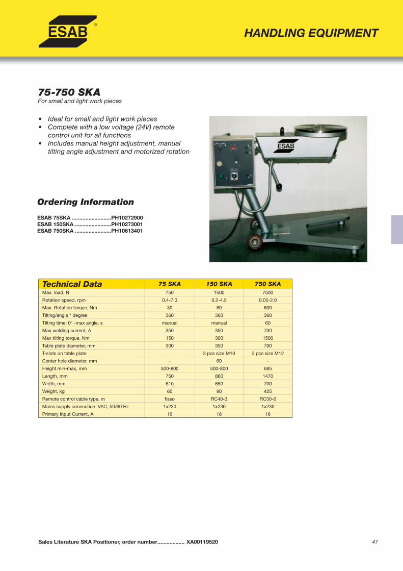
47
HANDLING EQUIPMENT
75-750 SKAFor small and light work pieces
• Ideal for small and light work pieces• Complete with a low voltage (24V) remote
control unit for all functions• Includes manual height adjustment, manual
tilting angle adjustment and motorized rotation
Sales Literature SKA Positioner, order number .................. XA00119520
Ordering Information
ESAB 75SKA ..........................PH10272900ESAB 150SKA ........................PH10273001ESAB 750SKA ........................PH10613401
Technical Data 75 SKA 150 SKA 750 SKAMax. load, N 750 1500 7500
Rotation speed, rpm 0.4-7.0 0.2-4.5 0.05-2.0
Max. Rotation torque, Nm 30 80 600
Tilting/angle ° degree 360 360 360
Tilting time: 0° -max angle, s manual manual 60
Max welding current, A 350 350 700
Max tilting torque, Nm 150 300 1500
Table plate diameter, mm 300 350 700
T-slots on table plate 3 pcs size M10 3 pcs size M12
Center hole diameter, mm - 60 -
Height min-max, mm 500-800 500-800 685
Length, mm 750 860 1470
Width, mm 610 650 700
Weight, kg 60 90 425
Remote control cable type, m fi sso RC40-3 RC30-6
Mains supply connection VAC, 50/60 Hz 1x230 1x230 1x230
Primary Input Current, A 16 16 16

48
HANDLING EQUIPMENT
Ordering Information
ESAB 750SHA ....................... PH10537300ESAB 1500SHA ..................... PH10537400ESAB 3500SHA ..................... PH10537500ESAB 5000SHA ..................... PH10537600ESAB 7000SHA ..................... PH10537700ESAB 10000SHA ................... PH10537800
750-10000 SHAPositioners for demanding and heavy work pieces
• Handle large and demanding work pieces in all positions
• Equipped with adjustable hydraulics with built-in safety valves
• 3-axis operation (height, tilting angle, androtation) for ideal ergonomic working conditions
• Low voltage (24 V) remote control with allfunctions
• Rotation and tilting speed controlled by vector inverters for improved accuracy and betterrotation torque
• Drives equipped with an AC motor• Plug & play connection to accessories available
including external connection, start/stop foot pedal, speed control foot pedal, and PEHprocess controller
Technical Data 750 SHA 1500 SHA 3500 SHA 5000 SHA 7000 SHA 10000 SHAMax. load, N 7500 15000 35000 50000 70000 100000
Rotation speed, rpm 0.05-2.0 0.02-1.3 0.05-1.6 0.01-1.5 0.03-1.0 0.02-0.75
Max. Rotation torque, Nm 600 1000 2800 6000 9000 18000
Tilting speed, rpm 0.1-1.5 0.1-1.5 0.1-1.0 0.1-0.75 0.1-0.75 0.1-0.75
Tilting torque , Nm 1500 3000 6000 10000 15000 20000
Adjustable tilting axle height min-max, mm
700-1500 700-1500 1100-1900 1200-20001200-2000 1200-2000
Off set distance mm 400 400 400 500 500 500
Max welding current, A 700 700 700 1400 1400 1400
Max work piece diameter, mm 2000 2500 3000 3200 3500 4000
Table plate diameter, mm 700 700 950 1100 1100 1490
T-slots on table plate 3 pcs M12 3 pcs M12 4 pcs M20 4 pcs M20 4 pcs M20 4 pcs M24
Height, mm 2110 2200 3060 3200 3200 4000
Length, mm 2240 2650 3710 4400 4700 5490
Width, mm 940 1160 1450 2040 2040 2140
Weight, kg 1200 1700 4950 9550 10800 13500
Remote control cable type, m RC30- 6 RC30- 6 RC30- 6 RC30- 6 RC30- 12 RC30- 12
Mains supply connection VAC, 60 Hz 460/575 3ph 460/575 3ph 460/575 3ph 460/575 3ph 460/575 3ph 460/575 3ph
Primary Input Current, A 16 20 25 25 25 32
Sales Literature SHA Positioner, order number .................. XA00119620

49
HANDLING EQUIPMENT
Ordering Information
ESAB 3500 FA .................................... PH10366100ESAB 7000 FA .................................... PH10366200ESAB 15000 FA .................................. PH10366300ESAB 25000 FA .................................. PH10366400ESAB 35000 FA .................................. PH10366500ESAB 50000 FA .................................. PH10366600ESAB 75000 FA .................................. PH10366700ESAB 100000 FA ................................ PH10366800
3500-100000 FAPositioners for automated circumferential welding
• Ideal for large and heavy work pieces• Complete with a low voltage (24 V) remote
control unit for all functions• Motorized rotation and tilting for ideal positioning• Vector inverter control system for constant and
precise speed• Hydraulically actuated tilting with safety valves• Drives equipped with AC motors• Plug&Play connection to accessories available
including external connection, start/stop footpedal, speed control foot pedal, and PEHprocess controller
Sales literature, FA series, order number ............................ XA00101420
Technical Data 3500 FA 7000 FA 15000 FA 25000 FA 35000 FA 50000 FA 75000 FA 100000 FA
Max. load, N 35000 70000 150000 250000 350000 500000 750000 1000000
Rotation speed, rpm 0.05-1.6 0.03-1.0 0.01-0.75 0.005-0.4 0.005-0.4 0.003-0.2 0.003-0.2 0.003-0.2
Max. Rotation torque, Nm 2800 9000 18000 40000 55000 75000 110000 150000
Tilting angle, ° degrees 135 135 135 120 120 110 110 110
Tilting time from 0 to max, sec 30 55 60 80 160 180 180 180
Max tilting torque, Nm 7500 14000 70000 175000 280000 400000 600000 800000
Max welding current, A 700 1400 1400 2100 2100 2100 2100 2100
Table plate diameter, mm 950 1100 1490 1950 1950 1950 1950 1950
T-slots on table plate 3 pcs M20 4 pcs M20 4 pcs M24 8 pcs M24 6 pcs M24 8 pcs M30 8 pcs M36 8 pcs M36
Height, mm 1100 1300 1500 2500 2500 2500 2750 2750
Length, mm 1750 2100 3000 4100 4100 4500 4500 4800
Width, mm 1150 1350 1600 1950 2450 2450 2450 2450
Weight, kg 1200 2700 5500 11000 12000 15000 18000 25000
Remote control cable type, m RC30-6 RC30-8 RC30-12 RC30-12 RC30-12 RC30-12 RC30-12 RC30-12
Mains supply VAC, 50 Hz 3x400V+N+PE 3x400V+N+PE 3x400V+N+PE 3x400V+N+PE 3x400V+N+PE 3x400V+N+PE 3x400V+N+PE 3x400V+N+PE
Primary input current, A 25 25 25 25 35 35 50 50

50
HANDLING EQUIPMENT
Ordering Information
ESAB 25000CRA ................................ PH10543000ESAB 35000CRA ................................ PH10543100ESAB 50000CRA ................................ PH10543200
25000-50000 CRAPositioners for highly demanding and large work pieces
• Ideal for large and heavy work pieces• Complete with a low voltage (24V) remote
control unit for all functions• Adjustable rotation and tilting for ideal
positioning• Vector inverter control system for constant and
precise speed • Drives equipped with an AC motor• Plug & play connection to accessories available
including external connection, start/stop foot pedal, speed control foot pedal, and PEHprocess controller
Sales Literature CRA Positioner, order number ................. XA00119820
Technical Data 25000 CRA 35000 CRA 50000 CRAMax. load, N 250000 350000 500000
Rotation speed, rpm 0.01-0.4 0.01-0.4 0.004-0.2
Max. Rotation torque, Nm 40000 55000 75000
Tilting speed, rpm 0.03-0.3 0.03-0.3 0.03-.03
Tilting torque, Nm 70000 110000 150000
Off set distance, mm 600 800 800
Max welding current, A 2100 2100 2100
Max work piece diameter, mm 6000 7000 7000
Table plate diameter, mm 1490 1490 1950
T-slots on table plate 8 pcs size M24 8 pcs size M24 8 pcs size M30
Height, mm 5100 5400 5600
Length, mm 9340 10600 10600
Width, mm 3160 3660 4000
Weight, kg 22000 34000 43000
Remote control cable type, m RC30-12 RC30-12 RC30-12
Mains supply connection VAC, 60 Hz 460/575 3ph 460/575 3ph 460/575 3ph
Primary Input Current, A 32 32 32

51
Ordering Information Motorized Rotation, Fixed or Adjustable Height750 HSA ..................................................................... PH10538000750 TSA ...................................................................... PH105396001500 HSA ................................................................... PH105381001500 TSA .................................................................... PH105397003500 HSA ................................................................... PH105382003500 TSA .................................................................... PH105398007000 HSA ................................................................... PH105383007000 TSA .................................................................... PH1053990015000 HSA ................................................................. PH1053840015000 TSA .................................................................. PH1054000025000 HSA ................................................................. PH1053850025000 TSA .................................................................. PH1054010035000 HSA ................................................................. PH1053860035000 TSA .................................................................. PH1054020050000 HSA ................................................................. PH1053870050000 TSA .................................................................. PH10540300
Height Extension Blocks750 HSA/HSLA Extension ........................................ PH106507001500 HSA/HSLA Extension ...................................... PH106507003500 HSA/HSLA Extension ...................................... PH106508007000 HSA/HSLA Extension ...................................... PH1065090015000 HSA/HSLA Extension .................................... PH1065100025000 HSA/HSLA Extension .................................... PH1065110035000 HSA/HSLA Extension .................................... PH1065120050000 HSA/HSLA Extension .................................... PH10651300
HANDLING EQUIPMENT
750-50000 Head & TailstockPositioners for long revolving workpieces
• Ideal for circumferential welding and assembly of diffi cult workpieces
• Complete with a low voltage (24V) remotecontrol unit for all functions
• Use headstock with or without tailstock• Head & tailstock can be equipped with a
stepless height adjustment and tailstock with hydraulic motorized rail-bogie for various lengths
• Plug & play connection to accessories available including external connection, rail bogies, start/stop foot pedal, and PEH process controller
• Headstock HSA features motorized rotation and fi xed height
• Headstock HSLA features motorized rotation and stepless height adjustment
• Tailstock TSA/TSLA features freely rotating table plate, and fi xed/adjustable height
Sales Literature Head and Tailstock, order number .....................................XA00119320
Motorized Railbogies750 RBTSA ................................................................ PH105412001500 RBTSA .............................................................. PH105413003500 RBTSA .............................................................. PH105414007000 RBTSA .............................................................. PH1054150015000 RBTSA ............................................................ PH1054160025000 RBTSA ............................................................ PH1054170035000 RBTSA ............................................................ PH1054180050000 RBTSA ............................................................ PH10541900
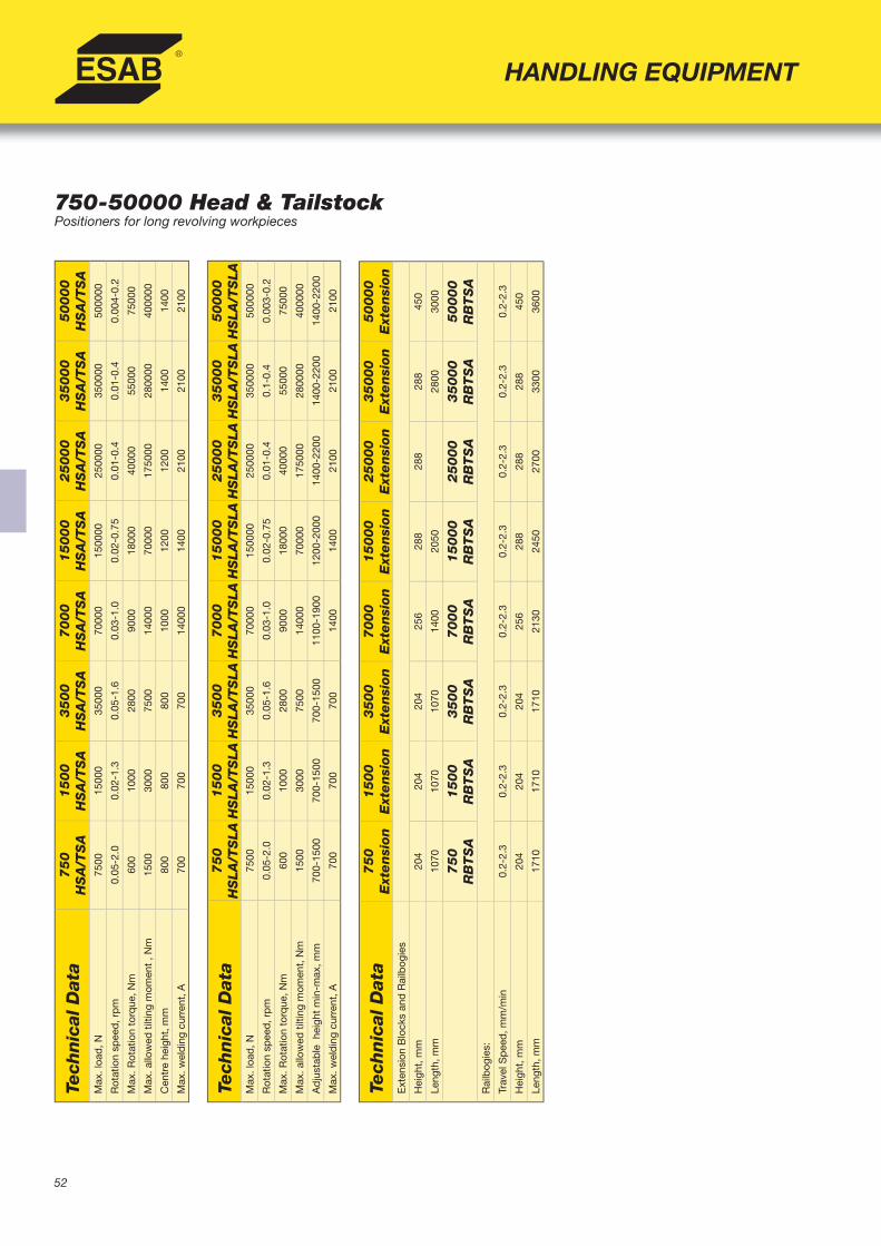
52
750-50000 Head & TailstockPositioners for long revolving workpieces
HANDLING EQUIPMENTTe
chnic
al D
ata
75
0H
SA
/TS
A1
50
0H
SA
/TS
A3
50
0H
SA
/TS
A7
00
0H
SA
/TS
A1
50
00
H
SA
/TS
A25000
HS
A/T
SA
35000
HS
A/T
SA
50000
HS
A/T
SA
Max
. loa
d, N
75
0015
000
3500
070
000
1500
0025
0000
3500
0050
0000
Rot
atio
n sp
eed
, rp
m0.
05-2
.00.
02-1
.30.
05-1
.60.
03-1
.00.
02-0
.75
0.01
-0.4
0.01
-0.4
0.00
4-0.
2
Max
. Rot
atio
n to
rque
, Nm
600
1000
2800
9000
1800
040
000
5500
075
000
Max
. allo
wed
tilt
ing
mom
ent
, Nm
1500
3000
7500
1400
070
000
1750
0028
0000
4000
00
Cen
tre
heig
ht, m
m80
080
080
010
0012
0012
0014
0014
00
Max
. wel
din
g cu
rren
t, A
700
700
700
1400
014
0021
0021
0021
00
Tech
nic
al D
ata
75
0H
SLA
/TS
LA
15
00
H
SLA
/TS
LA
35
00
H
SLA
/TS
LA
70
00
H
SLA
/TS
LA
15
00
0
HS
LA
/TS
LA
25000
HS
LA
/TS
LA
35000
HS
LA
/TS
LA
50000
HS
LA
/TS
LA
Max
. loa
d, N
75
0015
000
3500
070
000
1500
0025
0000
3500
0050
0000
Rot
atio
n sp
eed
, rp
m0.
05-2
.00.
02-1
.30.
05-1
.60.
03-1
.00.
02-0
.75
0.01
-0.4
0.1-
0.4
0.00
3-0.
2
Max
. Rot
atio
n to
rque
, Nm
600
1000
2800
9000
1800
040
000
5500
075
000
Max
. allo
wed
tilt
ing
mom
ent,
Nm
1500
3000
7500
1400
070
000
1750
0028
0000
4000
00
Ad
just
able
hei
ght
min
-max
, mm
70
0-15
0070
0-15
0070
0-15
0011
00-1
900
1200
-200
014
00-2
200
1400
-220
014
00-2
200
Max
. wel
din
g cu
rren
t, A
700
700
700
1400
1400
2100
2100
2100
Tech
nic
al D
ata
75
0
Ext
en
sion
15
00
E
xten
sion
35
00
Ext
en
sion
70
00
Ext
en
sion
15
00
0
Ext
en
sion
25000
E
xtensi
on
35000
E
xtensi
on
50000
E
xtensi
on
Ext
ensi
on B
lock
s an
d R
ailb
ogie
s
Hei
ght,
mm
204
204
204
256
288
288
288
450
Leng
th, m
m10
7010
7010
7014
0020
5028
0030
00
75
0
RB
TS
A1
50
0R
BT
SA
35
00
RB
TS
A7
00
0R
BT
SA
15
00
0R
BT
SA
25000
RB
TS
A35000
RB
TS
A50000
RB
TS
AR
ailb
ogie
s:
Trav
el S
pee
d, m
m/m
in0.
2-2.
30.
2-2.
30.
2-2.
30.
2-2.
30.
2-2.
30.
2-2.
30.
2-2.
30.
2-2.
3
Hei
ght,
mm
204
204
204
256
288
288
288
450
Leng
th, m
m17
1017
1017
1021
3024
5027
00
3300
3600

53
MECHANIZED TIG
Aristo™MechTig C2002i, Aristo™MechTig 4000i,Aristo™ MechControl 2 & 4
• Aristo™ MechTig C2002i is a compact, robust and easy-to-use 200A power generator, with built-in cooling unit for the water cooled torches, control system with graphic interface, program library and capacity of self-generation of welding programmes.
• Aristo™ MechControl 2 is a control unit featuring the same functions of the Aristo™ MechTig C2002i, but without power generator generator and cooling unit.
• Aristo™ MechControl 4 is similar to Aristo™ MechControl 2, with in addition AVC (Arc Voltage Control) and weavingfunctions.
• Aristo™MechTig 4000i is a power generator to be used in conjunction with the Aristo™ MechControl 2 or Aristo™ MechControl 4 control units, having 400A capacity and built-in cooling unit for water-cooled torches.
• The large 10” colour display helps obtaining the bestperformances and the Windows user interface make it easy searching programmes from the integrated library or the automatic generation of customized programmes, simply introducing data such as type of material, external diameter and tube wall thickness.
• New programmes can be added to the existing library. Alternatively, all welding parameters can be manually set by means of a graphic interface or electronic spreadsheet.
• Integrated printer, to produce copy on paper of theprogrammed welding parameters and of the measuredvalues related to speed, current, voltage, wire and power.
• USB (Universal Serial Bus) connection to transfer welding programmes between different machines, to store and to update programmes.
• ESAB offers a wide range of welding heads compatiblewith the new machines, to build complete orbital welding systems suitable for all applications.
• The Weldoc WMS 4000 monitoring and documentation system is available, to satisfy the needs of the ISO 9000/SS-EN729 international quality system. Alternatively, the SPS 4000 system can store the pre-set programmes.
• The MechT 1 CAN remote control unit has the ability tocontrol and display data.
Aristo™MechTig C20021i
Aristo™MechTig 4000 with Aristo™MechControl
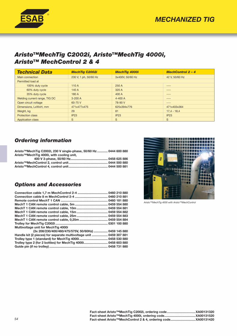
54
MECHANIZED TIG
Ordering information
Aristo™MechTig C2002i, 230 V single-phase, 50/60 Hz ............ 0444 600 880Aristo™MechTig 4000i, with cooling unit, 400 V 3-phase, 50/60 Hz .......................................... 0458 625 886Aristo™MechControl 2, control unit ............................................ 0444 500 880Aristo™MechControl 4, control unit ............................................ 0444 500 881
Options and AccessoriesConnection cable 1,7 m MechControl 2-4 .................................. 0460 210 880Connection cable 8 m MechControl 2-4 ..................................... 0460 210 881Remote control MechT 1 CAN ..................................................... 0460 181 880MechT 1 CAN remote control cable, 5m ..................................... 0459 554 880MechT 1 CAN remote control cable, 10m ................................... 0459 554 881MechT 1 CAN remote control cable, 15m ................................... 0459 554 882MechT 1 CAN remote control cable, 25m ................................... 0459 554 883MechT 1 CAN remote control cable, 0,25m ................................ 0459 554 884Trolley for MechTig C2002i ........................................................... 0301 100 880Multivoltage unit for MechTig 4000i (3x 208/230/400/460/475/575V, 50/60Hz) ................ 0459 145 880Handle kit (2 pieces) for separate multivoltage unit .................. 0459 307 881Trolley type 1 (standard) for MechTig 4000i ................................ 0458 530 880Trolley type 2 (for 2 bottles) for MechTig 4000i ........................... 0458 603 880Guide pin (if no trolley) .................................................................. 0458 731 880
Fact-sheet Aristo™MechTig C2002i, ordering code ................................XA00131320Fact-sheet Aristo™MechTig 4000i, ordering code ...................................XA00131520Fact-sheet Aristo™MechControl 2 & 4, ordering code ............................XA00131420
Technical Data MechTig C2002i MechTig 4000i MechControl 2 – 4
Main connection 230 V, 1 ph, 50/60 Hz 3x400V, 50/60 Hz 42 V, 50/60 Hz
Permitted load at
100% duty cycle 110 A 250 A ----
60% duty cycle 140 A 320 A ----
35% duty cycle 180 A 400 A ----
Welding current range, TIG DC 3-200 A 4-400 A ----
Open circuit voltage 60-75 V 78-90 V ----
Dimensions, LxWxH, mm 471x477x475 625x394x776 471x403x364
Weight, kg 29 81 17,4 - 18,4
Protection class IP23 IP23 IP23
Application class S S S
Aristo™MechTig C2002i, Aristo™MechTig 4000i,Aristo™ MechControl 2 & 4
Aristo™MechTig 4000 with Aristo™MechControl

55
Ordering Information
All PRB weld heads include 7 m of connection cablePRB 17-49, water cooled ....................................... 0443 750 880PRB 17-49, air cooled ............................................. 0443 750 881PRB 33-90, water cooled ....................................... 0443 760 880PRB 33-90, air cooled.............................................. 0443 760 881PRB 60-170, water cooled ..................................... 0443 770 880PRB 60-170, air cooled............................................ 0443 770 881
Options and Accessories Angular Support Bracket ....................................... 0443 875 880Rebuilding kit, PRB/PRC 17-49 ............................. 0444 002 880 For welding tubes with OD of 8-17 mmRebuilding kit, PRB/PRC 33-90 .............................. 0443 908 880 For welding tubes with OD of 20-33 mmRebuilding kit PRB/PRC 60-170 ............................. 0443 909 880 For welding tubes with OD of 44-60 mm
A21 PRBTube to Tube Weld Heads
• Small, fl exible, and lightweight• Heads based on unique clamp-on principle to
reduce set-up time• Available in air-cooled or water-cooled versions• Available in three sizes for tubes with outer diameters
of 17 mm to 170 mm• Use with Aristo™MechTig power sources• Complete with 7 m connection cable
Instruction Manual PRB Welding Head, order number ......... 0443808001Sales Literature PRB Welding Head, order number ............. XA00098520
MECHANIZED TIG
Technical Data PRB 17-49 PRB 33-90 PRB 60-170Rate of rotation, rpm 0.1-2.4 0.1-1.6 0.04-0.95
Tube OD, mm 17-49 33-90 60-170
Tube OD, mm Option 8-17 20-33 44-60
Max welding current at 100% duty cycle, water-cooled, A 250 250 250
Max welding current at 100% duty cycle, air-cooled, A 100 100 100
Electrode diameter, mm 1.6-2.4 1.6-2.4 1.6-2.4
Weight (less cables), kg 2.8 3.2 4.4
Minimum spacing required between two parallel tubes, mm D/2+70* D/2+94* D/2+137
* Without fi ne adjustment wheel for wire. Electrode cap and spacer screw may need to be replaced with the shortest variant supplied with the tool

56
A21 PRC Flexible Tube to Tube Weld Heads
• Water-cooled • Features arc weaving movement and arc voltage
control • Increase productivity and quality of weld,
particularly when welding thick-walled tubes• Use in combination with Aristo™MechTig power
sources
Instruction Manual PRC Welding Head, order number ....... 0443934001Sales Literature PRC Welding Head, order number .......... XA00098520
MECHANIZED TIG
Ordering InformationPRC 17-49 with AVC ................................................ 0443 751 880PRC 17-49 with AVC and weaving ......................... 0443 752 880PRC 33-90 with AVC ................................................ 0443 761 880PRC 33-90 with AVC and weaving ......................... 0443 762 880PRC 60-170 with AVC .............................................. 0443 771 880PRC 60-170 with AVC and weaving ....................... 0443 772 880
Options and Accessories Angular Support Bracket ........................................ 0443 875 880Rebuilding kit, PRB/PRC 17-49 ............................. 0444 002 880 For welding tubes with OD of 8-17 mmRebuilding kit, PRB/PRC 33-90 .............................. 0443 908 880 For welding tubes with OD of 20-33 mmRebuilding kit PRB/PRC 60-170 ............................. 0443 909 880 For welding tubes with OD of 44-60 mm
Technical Data PRC 17-49 PRC 33-90 PRC 60-170Rate of rotation, rpm 0.1-2.4 0.1-1.6 0.05-0.95
Tube OD, mm 17-49 33-90 60-170
Tube OD with options, mm 8-17 20-33 44-60
Max welding current 100% duty cycle, water-cooled, A 250 250 250
Electrode diameter, mm 1.6-2.4 1.6-2.4 1.6-2.4
Weight with arc length control (less cables), kg 3.3 3.7 4.9
Weight with arc length control and weave unit (less cables), kg 5.1 5.5 6.7
Arc length control, Arc adjustment rate, mm/s 2.5 2.5 2.5
Oscillation:
Adjustment range, mm/s 20 20 20
Amplitude, mm +/- 6 +/- 6 +/- 6
Weave speed, mm/s 2-12 2-12 2-12
Minimum spacing required between two parallel tubes, mm D/2+70* D/2+94* D/2+137
* Without fi ne adjustment wheel for wire. Electrode cap and spacer screw may need to be replaced with the shortest variant supplied with the tool

57
Options and Accessories
PRD 160 Weld HeadWeave unit complete .............................................. 0444 140 880Wire feeder unit complete ..................................... 0444 137 880AVC (Arc Voltage Control) complete ...................... 0443 656 881
PRD 100 Weld HeadStraight rack with suction feet, 2 m ...................... 0334 150 880Straight rack with suction feet, 4 m ....................... 0334 150 881
Ordering Information
PRD 160 Weld HeadBasic unit, intended only for fusion weldingwith a fl oating head ......................................................... 0444 151 880Basic unit with wire feeder unit complete ..................... 0444 151 881Basic unit with AVC (Arc Voltage Control) ..................... 0444 151 882Basic Unit with AVC plus wire feeder unit complete .... 0444 151 883Basic Unit with AVC plus wire feeder unit completeand wave unit .................................................................... 0444 151 884
TPRD 100 Weld HeadPRD 100 Unit ..................................................................... 0444 016 880Narrow Gap head, 50mm ................................................ 0441 623 880Narrow Gap head, 80mm ................................................. 0441 623 881
A21 PRD
Orbital Tube Weld Heads• Precision TIG tube and pipe welding heads that are rugged
and easy to use• Water-cooled, designed for up to 400 Amps PRD 160 Weld Head• For pipes with OD of 160 mm and greater• Use with Aristo™MechTig power sources• Modular design allows wire feed, Arc Voltage Control,
and weaving unit to be added to basic
PRD 100 Weld Head• For pipes with OD of 100 mm and greater• Compact low-profi le design- requires only 73 mm clearance
around pipe• Use with Aristo™MechTig power source• Standard features include synchronized current pulsing with
wire feed and carriage movement, arc weaving, and automaticArc Voltage Control
• Capable of TIG Narrow Gap Orbital welding (with optional head) to achieve increased productivity and reduced heat input on tubes with a wall thickness greater than 10 mm
Instruction Manual PRD 100, order number .................................... 0444061001Instruction Manual PRD 160, order number .................................... 0444100001Sales Literature PRD 100, order number......................................... XA00091720Sales Literature PRD 160, order number...................................... Contact ESAB
MECHANIZED TIG
Note: the PRD orbital welding heads move on racks embracing the tube to be welded. Racks are available suited for tube diametersfrom 100 to 1000 mm.
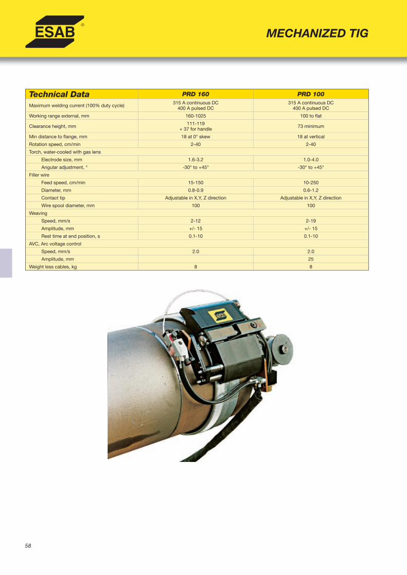
58
MECHANIZED TIG
Technical Data PRD 160 PRD 100
Maximum welding current (100% duty cycle) 315 A continuous DC400 A pulsed DC
315 A continuous DC400 A pulsed DC
Working range external, mm 160-1025 100 to fl at
Clearance height, mm 111-119 + 37 for handle 73 minimum
Min distance to fl ange, mm 18 at 0° skew 18 at vertical
Rotation speed, cm/min 2-40 2-40
Torch, water-cooled with gas lens
Electrode size, mm 1.6-3.2 1.0-4.0
Angular adjustment, ° -30° to +45° -30° to +45°
Filler wire
Feed speed, cm/min 15-150 10-250
Diameter, mm 0.8-0.9 0.6-1.2
Contact tip Adjustable in X,Y, Z direction Adjustable in X,Y, Z direction
Wire spool diameter, mm 100 100
Weaving
Speed, mm/s 2-12 2-19
Amplitude, mm +/- 15 +/- 15
Rest time at end position, s 0.1-10 0.1-10
AVC, Arc voltage control
Speed, mm/s 2.0 2.0
Amplitude, mm 25
Weight less cables, kg 8 8
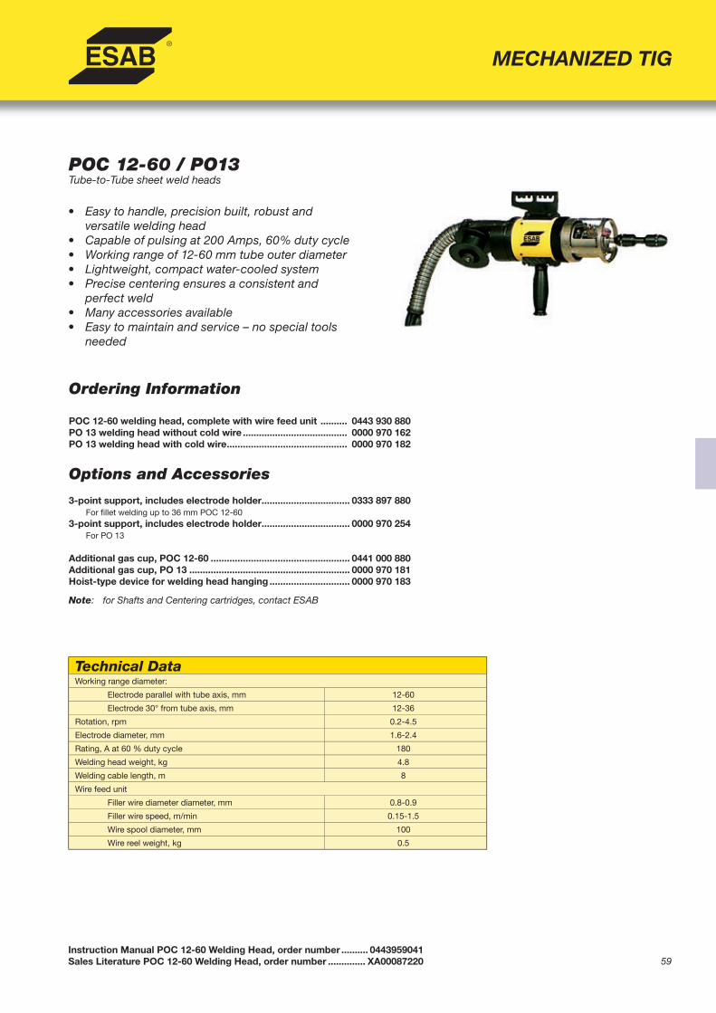
59
Ordering Information
POC 12-60 welding head, complete with wire feed unit .......... 0443 930 880PO 13 welding head without cold wire ....................................... 0000 970 162PO 13 welding head with cold wire ............................................. 0000 970 182
Options and Accessories 3-point support, includes electrode holder ................................. 0333 897 880 For fi llet welding up to 36 mm POC 12-60 3-point support, includes electrode holder ................................. 0000 970 254
For PO 13
Additional gas cup, POC 12-60 .................................................... 0441 000 880Additional gas cup, PO 13 ............................................................ 0000 970 181Hoist-type device for welding head hanging .............................. 0000 970 183
• Easy to handle, precision built, robust and
versatile welding head • Capable of pulsing at 200 Amps, 60% duty cycle• Working range of 12-60 mm tube outer diameter• Lightweight, compact water-cooled system• Precise centering ensures a consistent and
perfect weld• Many accessories available• Easy to maintain and service – no special tools
needed
Instruction Manual POC 12-60 Welding Head, order number .......... 0443959041Sales Literature POC 12-60 Welding Head, order number .............. XA00087220
MECHANIZED TIG
POC 12-60 / PO13Tube-to-Tube sheet weld heads
Technical DataWorking range diameter:
Electrode parallel with tube axis, mm 12-60
Electrode 30° from tube axis, mm 12-36
Rotation, rpm 0.2-4.5
Electrode diameter, mm 1.6-2.4
Rating, A at 60 % duty cycle 180
Welding head weight, kg 4.8
Welding cable length, m 8
Wire feed unit
Filler wire diameter diameter, mm 0.8-0.9
Filler wire speed, m/min 0.15-1.5
Wire spool diameter, mm 100
Wire reel weight, kg 0.5
Note: for Shafts and Centering cartridges, contact ESAB

60
• Protects the welding arc with shielding gas
from external environments• Weld without fi ller material • Rotating components and tungsten electrode are
enclosed in gas chamber formed by outer casing• Thin water-cooled design- for use where
clearances are limited• Available in three sizes for pipes with outer
diameter ranging from 3 mm up to 76.2 mm • All heads equipped with encoder motors for precise
positioning of each sector when welding various parameters
• May be used with Aristo™MechTig power sources
Ordering Information
Welding head PRH 3-12 .......................................... 0444 300 880Welding head PRH 3-38 .......................................... 0444 301 880Welding head PRH 6-76 .......................................... 0444 302 880
Instruction Manual PRH Welding Head, order number .......... 0444291104Sales Literature PRH Welding Head, order number ...............XA00115920
MECHANIZED TIG
A21 PRHEnclosed tube welding heads
Technical Data PRH 3-12 PRH 3-38 PRH 6-76Rate of rotation, rpm 0.65-12.6 0.5-9.5 0.31-6.15
Tube OD, mm 3-12.7 3-38.1 6-76.2
Max. continuous welding current,100% duty cycle, water cooled, A
15 50 60
Max. pulsed welding current, water-cooled, A
40 100 100
Electrode diameter, mm 1.0 1.6/2.4 1.6/2.4
Weight (with cables), kg 5.0 6.5 7.5

61
• Modular components can be easily combined to
create customized solution for specifi c welding tasks
• Available add-on components: • Rotary slide for adjusting the torch angle • Motorized slide for Arc Voltage Control (AVC) • Motorized slide for weaving • Floating head • Narrow Gap kit for BTE 500M • VEC motor with pulse-controlller for rotation of
the work piece or connection to a turn table• Available with either a BTE 250M (max 250 A)
or BTE 500M (max 500 A) TIG torch• For use with Aristo™MechTig power sources
Accessory Components 1. Bracket 0441 404 880 2. Wire feed unit diam 0.6-0.8 mm 0441 300 882 3. Feed roller diam 1.0-1.2 mm 0369 557 003 4. Feed roller diam 1.2-1.6 mm 0369 557 007 5. Outlet pipe diam 0.8-1.2 mm 0441 456 881 6. Outlet pipe diam 1.6 mm 0441 456 882 7. Connection cable, feed unit 8 m 0443 828 880 8. Wire hose, per meter 0192 799 112 9. Wire nozzle, BTE 250M 0441 407 880 10. Wire nozzle, BTE 500M 0441 407 881 11. TIG torch BTE 250M 0441 362 880 12. TIG torch BTE 500M 0441 418 880 13. Holder BTE 250M 0441 414 880
Instruction Manual BTE Torch, order number .......................... 0443424001Instruction Manual A25 Welding Station, order number ......... 0443922001Sales Literature A25 Welding Station, order number ............. XA00089520
MECHANIZED TIG
A25 Components SystemMechanized TIG Modular Component System
Ordering Information
A25 TIG welding system complete with: BTE 250M Torch(1) BTE 500M Torch(2)AVC ................................................................................... 0443 911 880 .......................... 0443 911 881AVC and Weaving slides ................................................. 0443 911 882 .......................... 0443 911 883AVC and manual horizontal slides ................................. 0443 911 884 .......................... 0443 911 885Manual vertical and horizontal slides ............................ 0443 911 886 .......................... 0443 911 887Slides for fl oating heads ................................................. 0443 912 880 .......................... 0443 912 881AVC and weaving slides mounted on a stand, with VEC motor and turntable ................................................ 0443 910 880 .......................... 0443 910 881(1) Delivered as standard for following wire diameters: 0,6 -1,2 mm(2) Delivered as standard for following wire diameters: 0,6-0,8 1,2-1,6 mm
14. Holder BTE 500M 0441 414 881 15. Slide AVC 0443 913 880 16. Circular slidee 0145 945 880 17. Slide manual 0413 518 880 18. Slide weaving 0443 913 881 19. Slide fl oatinge 0441 674 881 20. Single guide wheel unit, BTE 250M 0441 833 880 Single guide wheel unit, BTE 500M 0441 833 881 21. Double guide wheel unit, BTE 250M 0441 358 880 Double guide wheel unit, BTE 500M 0441 358 881 22. Bracket 0441 412 880 23. Brake hub 0146 967 881 24. Bobbin protection 0157 482 880

62
MEI 21 • Four-roll drive system• Easily connected to welding head through a
fl exible wire guide• Can use 5 kg wire spools • Use with wire diameters from 0.6-0.8 mm• Geared DC drive motor with microprocessor
closed-loop feedback ensures precise wirefeed speed
MEI 10 • Developed for mounting on PRB/PRC 17-170 tools
Instruction Manual MEI 21 Cold Wire Feed Unit, order number ....... 0443831001Instruction Manual MEI 10 Cold Wire Feed Unit, order number ....... 0444215001Sales Literature MEI 21 Cold Wire Feed Unit, order number ............ XA00089020Sales Literature MEI 10 Cold Wire Feed Unit, order number ............ XA00098620
MECHANIZED TIG
MEI 21 and MEI 10Wire feed unit for Mechanized TIG Welding
Ordering Information
MEI 21 Wire Feed Unit ......................................................... 0443 830 880MEI 10 for PRB/PRC 17-49 with AVC ................................. 0444 211 880MEI 10 for PRB 33-90, PRC 60-170 with AVCand PRC 33-90 with AVC and weaving .............................. 0444 212 880MEI 10 for PRB 60-170, PRC 60-170 with AVCand PRC 60-170 with AVC and weaving ............................ 0444 213 880
Technical Data MEI 21Motor
Current 48 V DC
Gear ratio 159:1
Rational speed, rpm 70-5500
Max. Output 50 W
Wire spool
Outer diameter, mm 200
Spool width, mm 60
Hub width, mm 60
Hub hole diameter, mm 51.5
Wire diameter, mm 0.6-0.8
Wire feed speed, m/min 0.1-2.6
Wire conduit length, m 4.2
Weight excl. wire spool, kg 4
Technical Data MEI 10Motor
Current 24 V DC
Gear ratio 159:1
Output torque, Nmm 300
Encoder, ppr 16
Filler wire steel, mm 0.8
Filler wire aluminium, mm 0.8-1.0
Wire feed speed, m/min 0.1-1.2
Weight excl. reel and cable, kg 0.5

63
Ordering InformationG-Tech Tungsten Grinder, 110/115 V, 1 ph, 60 H ... 0700 009 882Complete with one diamond grinding disc and accessory kitfor 1 to 4 mm electrodes
Options and Accessories Diamond grinding disc ............................................ 0700 009 002Grinder fl uid, 250 ml ................................................ 0700 009 004Return bottle, 250 ml ............................................... 0700 009 005Electrode clamp 1,0 mm ......................................... 0700 009 007Electrode clamp 1,6 mm ......................................... 0700 009 008Electrode clamp 2,4 mm ......................................... 0700 009 009Electrode clamp 3,2 mm ......................................... 0700 009 010Electrode clamp 4,0 mm ......................................... 0700 009 011Electrode holder, stainless ..................................... 0700 009 014Waste Container ...................................................... 0700 009 017Accessory kit, complete ......................................... 0700 009 020
• Unique enclosed wet grinding system• Stable, concentrated TIG welding arc-
guarantees accuracy and repeatability• Automatic collection of grinding dust-
no risk to welder or environment• No oxidation of the tungsten electrode
when wet grinding• Longer life of electrode point
Instruction Manual G-Tech Grinder, order number 0700009027Sales Literature G-Tech Grinder, order number .......... 898C129
MECHANIZED TIG
G-TechPrecision TIG Electrode Grinder
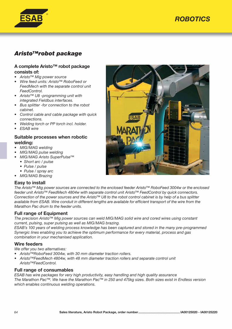
64
ROBOTICS
Aristo™robot package
A complete Aristo™ robot package consists of:• Aristo™ Mig power source• Wire feed units: Aristo™ RoboFeed or
FeedMech with the separate control unit FeedControl.
• Aristo™ U8 -programming unit withintegrated Fieldbus interfaces.
• Bus splitter -for connection to the robotcabinet.
• Control cable and cable package with quick connections.
• Welding torch or PP torch incl. holder.• ESAB wire
Suitable processes when robotic welding:• MIG/MAG welding• MIG/MAG pulse welding• MIG/MAG Aristo SuperPulse™ • Short arc / pulse • Pulse / pulse • Pulse / spray arc• MIG/MAG Brazing
Easy to installThe Aristo™ Mig power sources are connected to the enclosed feeder Aristo™ RoboFeed 3004w or the enclosed feeder unit Aristo™ FeedMech 4804w with separate control unit Aristo™ FeedControl by quick connectors.Connection of the power sources and the Aristo™ U8 to the robot control cabinet is by help of a bus splitteravailable from ESAB. Wire conduit in different lengths are available for effi cient transport of the wire from theMarathon Pac drum to the feeder units.
Full range of EquipmentThe precision Aristo™ Mig power sources can weld MIG/MAG solid wire and cored wires using constantcurrent, pulsing, super pulsing as well as MIG/MAG brazing. ESAB’s 100 years of welding process knowledge has been captured and stored in the many pre-programmed Synergic lines enabling you to achieve the optimum performance for every material, process and gascombination in your mechanised application.
Wire feedersWe offer you two alternatives:• Aristo™RoboFeed 3004w, with 30 mm diameter traction rollers.• Aristo™FeedMech 4804w, with 48 mm diameter traction rollers and separate control unit
Aristo™FeedControl.
Full range of consumablesESAB has wire packages for very high productivity, easy handling and high quality assurance The Marathon Pac™. We have the Marathon Pac™ in 250 and 475kg sizes. Both sizes exist in Endless version which enables continuous welding operations.
Sales literature, Aristo Robot Package, order number ................................................ IA00125020 - IA00125220

65
ROBOTICS
Aristo™Robot Package standard components for FieldBus communication
Aristo™Robot Package standard components for Retrofi t

66
Mechtrac 1730/2100/2500/3000Components for mechanized gantry automation
• Fast and fl exible way to increase productivity• Equipped with PEH process controller and A2
welding equipment for mechanized SAW orMIG welding
• Weld various profi les such as I-, T-, or L- beams, straight columns, or tapered columns
• Available in four versions (width of gantry):1730mm, 2100 mm, 2500 mm, or 3000 mm
• All versions have standard gantry leg height of1500 mm
• Floor mounted rail delivered in standard lengthsof 3 m - can be easily extended
• Dual-drive motors are standard on Mechtrac 2100/2500/3000, Mechtrac 1700 available as single or dual-drive
• Gantry can support a maximum weight of 220 kg up to two A2 weld heads, complete with GMD joint tracking, and OPC fl ux recovery systems
Ordering InformationMechtrac 1730, single drive .................................... 0809 670 880Mechtrac 1730, dual drive ...................................... 0809 670 881Mechtrac 2100, dual drive ...................................... 0809 670 882Mechtrac 2500, dual drive ...................................... 0809 670 883Mechtrac 3000, dual drive ...................................... 0809 670 884
Instruction Manual Mechtrac 1730/2100/2500/3000, order number ...... 0807230101Sales Literature Mechtrac 1730/2100/2500/3000, order number ........... XA00101220
APPLIED AUTOMATION
Options and AccessoriesTravelling rail, 3 m .................................................... 0806 707 880Travelling rail, extension, 3 m ................................. 0806 707 881
Technical DataTravel speed, m/min 0.2-1.9
Maximun load, kg 220
Standard rail length, m 3

67
ESAB CaB SystemsFlexible, Modular Column & Booms
• Modular design concept allows total customization using standard components • Large selection of available components to integrate for a custom solution: • Any A2 or A6 weld head system • PEH Process Controller with LAF/TAF power sources • ESAB turning rolls and positioners • ESAB fl ux feeding and recovery systems • GMD and Laser Joint Tracking Systems • Monitoring systems, cameras, WMS 4000 quality supervision software • Four basic station designs suitable for most standard applications • Three different sizes: 300, 460 and 600 (number refers to boom profi le height which determines working
range and load capability)• Different types of foundations available- stationary or rail-travelling carriage• A variety of options to cover any automation demands
APPLIED AUTOMATION
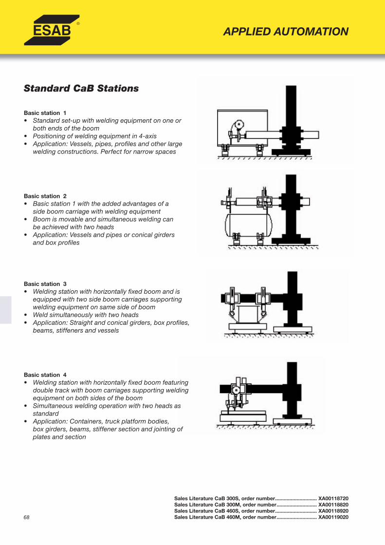
68
Standard CaB Stations
Basic station 1• Standard set-up with welding equipment on one or
both ends of the boom• Positioning of welding equipment in 4-axis• Application: Vessels, pipes, profi les and other large
welding constructions. Perfect for narrow spaces
Basic station 2• Basic station 1 with the added advantages of a
side boom carriage with welding equipment• Boom is movable and simultaneous welding can
be achieved with two heads• Application: Vessels and pipes or conical girders
and box profi les
Basic station 3• Welding station with horizontally fi xed boom and is
equipped with two side boom carriages supportingwelding equipment on same side of boom
• Weld simultaneously with two heads • Application: Straight and conical girders, box profi les,
beams, stiffeners and vessels
Basic station 4• Welding station with horizontally fi xed boom featuring
double track with boom carriages supporting weldingequipment on both sides of the boom
• Simultaneous welding operation with two heads asstandard
• Application: Containers, truck platform bodies,box girders, beams, stiffener section and jointing ofplates and section
APPLIED AUTOMATION
Sales Literature CaB 300S, order number ............................. XA00118720Sales Literature CaB 300M, order number ............................ XA00118820Sales Literature CaB 460S, order number ............................. XA00118920Sales Literature CaB 460M, order number ............................ XA00119020

69
Standard CaB Sizes
The manipulators are divided into three different sizes 300, 460 and 600. These sizes are the throat dimen-sions of the boom in millimeters. Each size has a corresponding column. The different sizes are not only limited in where it can fi t, but also how far the boom can extend and how much load that can be put on.
Performance Categories The system is divided into three different categories for performance:
S: Standard• Standard mechanical performance, no cable chain• A few options, camera-system, tacho-regulated speed and fl ux control• Only for Basic station 1
M: Modular• Standard mechanical performance, including cable chain for Columns and Booms• More than 20 options fully integrated, such as tandem, shift function, transport speed etc• Only for Basic station 1
C: Customized• Based on the same mechanical performance as the S- and M- model• Based on the same electrical system as the M- model• Includes everything that is not a S- or M- model such as: • Basic station 2, 3, and 4 • Odd sizes (ex. 4.35 m x 5.15 m) • Option demands not offered in S- or M- model.
APPLIED AUTOMATION
Sales Literature CaB S, M, C version, order number ........................... XA00095120

70
APPLIED AUTOMATION
CaB 300S/300M Basic Station 1ColumnEffective working range, m 3 4 5Max boom height A, using movable carriage, mm 4070 5070 6070
Min boom height A, using movable carriage, mm 950 950 950
Max boom height B, using concrete stand, mm 3955 4955 5955
Min boom height B, using concrete stand, mm 815 815 815
Max boom height C, using stationary foot plate, mm 3750 4750 5750
Min boom height C, using stationary foot plate, mm 610 610 610
Total height, D, using movable carriage, mm 5170 6170 7170
Total height, E, using concrete stand, mm 5055 6055 7055
Total height, F, using stationary foot plate, mm 4850 5850 6850Lifting speed, m/min 0.7 0.7 0.7
BoomEffective working range, m 3 4 5Max extension, G, mm 3580 4580 5580
Min extension, G, mm 540 540 540 Permissible loads -total, kg 300 220 150 -one end, kg 240 150 75 Cross sectional diameter, H, mm 325 325 325 Welding speed, m/min 0.1-2.0 0.1-2.0 0.1-2.0 Transport speed, m/min 2.0 2.0 2.0
Rail Carriage/Concrete Stand/Foot plateRail carriage track width, inside to inside, L, mm 1730 Rail carriage width x length, mm 2060 x 2330 Rail carriage height, I, mm 365 Welding speed, m/min 0.1-2.0 Transport speed, m/min 2.0 Concrete stand width x length, mm 2060 x 2100Concrete stand height, J, mm 250Foot plate width x length, mm 1100 x 1100Foot plate height, K, mm 40

71
APPLIED AUTOMATION
CaB 460S / 460M Basic Station 1ColumnEffective working range, m 4 5 6Max boom height A, using movable carriage, mm 4950 5950 6950Min boom height A, using movable carriage, mm 950 950 950Max boom height B, using concrete stand, mm 4845 5845 6845Min boom height B, using concrete stand, mm 845 845 845Max boom height C, using stationary foot plate, mm 4510 5510 6510Min boom height C, using stationary foot plate, mm 510 510 510Total height, D, using movable carriage, mm 6275 7275 8275Total height, E, using concrete stand, mm 6170 7170 8170Total height, F, using stationary foot plate, mm 5835 6835 7835Lifting speed, m/min 0.7 0.7 0.7
BoomEffective working range, m 4 5 6Max extension, G, mm 4850 5850 6850Min extension, G, mm 850 850 850Permissible loads -total, kg 1100 1050 1000 -one end, kg 550 450 350Cross sectional diameter, H, mm 630 630 630Welding speed, m/min 0.1-2.0 0.1-2.0 0.1-2.0 Transport speed, m/min 2.0 2.0 2.0
Rail Carriage/Concrete Stand/Foot plateRail carriage track width, inside to inside, L, mm 1730 Rail carriage width x length, mm 2100 x 2380 Rail carriage height, I, mm 485 Welding speed, m/min 0.1-2.0 Transport speed, m/min 2.0 Concrete stand width x length, mm 2100 x 2410Concrete stand height, J, mm 380 Foot plate width x length, mm 1600 x 1600Foot plate height, K, mm 40

72
ESAB Seamers for External WeldingLongitudinal seam welding machine
• Best solution for welding high quality longitudinalwelds to plates, tanks or other cylindrical work pieces
• Seamers are delivered ready to weld• Available for 1-6 m long welds and for diameters
150-1000 mm• Easy alignment of plates with help from laser light • Pneumatically operated stoppers for plate alignment
available• Water cooled backing bar• Copper backing bar equipped with shielding gas
for plasma and TIG processes• Manual and remote control operations with PLC
controller
APPLIED AUTOMATION
Sales Literature ED External Seamers, order number ................... XA001200020Sales Literature ID Internal Seamers, order number ..................... XA001200120
ESAB Seamers for Internal Welding
• Best solution for welding high quality longitudinalwelds to plates, tanks or other cylindrical work pieces
• Seamers are delivered ready to weld• Available for welding a max of 6 m long welds and
diameters greater than 1500 mm• Easy alignment of plates with help from laser light beam• Pneumatically operated stoppers for plate alignment
available• Copper backing bar equipped with shielding gas
for Plasma and TIG processes• Conserve shielding gas with divided gas valves• Manual and remote control operations with PLC
controller
Technical Data ED15H10 ED20H10 ED30H10 ED40H10 ED60H10Nominal length, mm 1500 2000 3000 4000 6000
Welding length, mm 1750 2250 3250 4250 6250
Minimum diameter, mm 180 180 250 350 600
Maximum diameter, mm1 1000 1000 1000 1000 1000
Plate thickness, mmnot tack-welded
1-8 1-8 1-8 1-8 1-8
Max plate thickness, mmtack-welded
10 10 10 10 10
1 Extension block available
Technical Data ID40H10 ID60H10Nominal length, mm) 4000 6000
Welding length, mm 4250 6250
Minimum diameter, mm 1500 1500
Plate thickness, mm not tack-welded 1-8 1-8
Max plate thickness, mm tack-welded 10 10

73Sales Literature ED External Seamers, order number ....................XA001200020Sales Literature ID Internal Seamers, order number ......................XA001200120
Ordering Information- Internal Seamers
Welding Equipment* ...................................... ID40H10 ID60H10SAW1 ................................................................................010696300 010696400SAW2 ...............................................................................010637600 010637700MIG1 .................................................................................010696500 010696600MIG2 .................................................................................010637800 010637900MIG3 .................................................................................010638000 010638100TIG1 ..................................................................................010638200 010638300TIG2 ..................................................................................010638400 010638500Plasma1 ............................................................................010638600 010638700Plasma2............................................................................010638800 010638900Plasma3............................................................................010639000 010639100
APPLIED AUTOMATION
Options and Accessories
AVC control for plasma equipment 010642300 010642300Camera monitoring systems 010642200 010642200Pneumatic plate stopper (3 required) 010645900 010645900
Ordering Information- External Seamers
Welding Equipment* ......................................ED15H10 ED20H10 ED30H10 ED40H10 ED60H10 SAW1 ................................................................................010695000 010695100 010695200 010695300 010695400SAW2 ...............................................................................010630900 010631000 010631100 010631200 010631300MIG1 .................................................................................010695500 010695600 010695700 010695800 010695900MIG2 ................................................................................. 010631400 010631500 010631600 010631700 010631800MIG3 ................................................................................. 010631900 010632000 010632100 010632200 010632300TIG1 ..................................................................................010632400 010632500 010632600 010632700 010632800TIG2 ..................................................................................010632900 010633000 010633100 010633200 010633300Plasma1 ............................................................................010633400 010633500 010633600 010633700 010633800Plasma2............................................................................010633900 010634000 010634100 010634200 010634300Plasma3............................................................................010634400 010634500 010634600 010634700 010634800
Options and Accessories500 mm high extension block .........................................010639200 010639300 010639400 010639500 010639600Plate stopper, required amount .......................................................2 2 2 2 2Stopper ring .....................................................................010639800 010639900 010640000 010640100 010640200
*Welding Equipment PackageSAW1 LAF 635 power source, A2 wire feeder with PEH control, OPC fl ux recovery unitSAW2 LAF 1000 power source, A2 wire feeder with PEH control, OPC fl ux recovery unitMIG1 ESABMig 500 power source, ESABFeed 48-4, M14 wire feeder, MIG torchMIG2 AristoMig 400 power source, AristoFeed 48-4W, MA6 wire feeder, MIG torchMIG3 AristoMig 450 power source, AristoFeed 48-4W, MA6 wire feeder, MIG torchTIG1 AristoTIG 400 power source, BTE500M TIG torchTIG2 AristoTIG 400 power source, MEI 10 and MEI 21 wire feeder (cold wire), BTE500M TIG torchPlasma 1 PLW202 200A power source, CWC3-CWF1 wire feeder, PTM150 plasma torchPlasma 2 PLW402 400A power source, CWC3-CWF1 wire feeder, PT300 plasma torchPlasma 3 PLW402 400A power source, CWC3-CWF1 wire feeder, PT8 plasma torch

74
Circotech Mechanized compact girth welding system
• Self propelled three o’clock welding system• Designed for on-site erection of large
storage tanks, silos, blast furnaces andcylindrical objects
• Available in single-sided or double-sided • Designed to travel along the edge of a tank shell,
on a rail temporarily attached to shell, or on a stand-alone ring outside the shell
• Equipped with caged cabin for maximum safety and easy to reach welding controls
• Standard equipment includes single-wire SAW, or twin wire SAW on request
• Utilizes ESAB’s fl ux supply and recovery system• Contributes to a consistent quality weld• Fully functional package consists of: Subarc
welding machine type A2 or A6 with motorised slides, PAK manual tracking system, PEHprocess controller, a weather shielded safetycabin, LAF power source, 6 l fl ux hopper and fl ux support, 50 m control cable, and welding and return cables
APPLIED AUTOMATION
Sales Literature Circotech, order number ........................XA00083620
Ordering Information
Contact ESAB
Technical DataPlates to be welded
Height, mm 1000-3000
Thickness, mm 8-35
Shell curvature, radius, mm 4000 min.
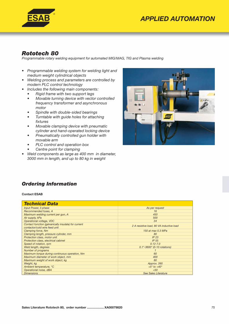
75
Rototech 80Programmable rotary welding equipment for automated MIG/MAG, TIG and Plasma welding
• Programmable welding system for welding light and medium weight cylindrical objects
• Welding process and parameters are controlled by modern PLC control technology
• Includes the following main components: • Rigid frame with two support legs • Movable turning device with vector controlled
frequency transformer and asynchronous motor
• Spindle with double-sided bearings • Turntable with guide holes for attaching
fi xtures • Movable clamping device with pneumatic
cylinder and hand-operated locking device • Pneumatically controlled gun holder with
movable arm • PLC control and operation box • Centre point for clamping• Weld components as large as 400 mm in diameter,
3000 mm in length, and up to 80 kg in weight
APPLIED AUTOMATION
Ordering Information
Contact ESAB
Sales Literature Rototech 80, order number ....................XA00079820
Technical DataInput Power, 3 phase As per requestRecommended fuses, A 16Maximum welding current per gun, A 450Air supply, kPa 500Operational voltage, VDC 24Contact function (galvanically insulate) for currentcontactor/cold wire feed unit
2 A resistive load, 80 VA inductive load
Clamping force, Nm 150 at max 0.3 MPaClamping length, pressure cylinder, mm 80Protection class, motor unit IP 23Protection class, electrical cabinet IP 55Speed of rotation, rpm 0.12-7.0Weld length, degrees 0.1°-3600° (0-10 rotations)Number of programs 1Maximum torque during continuous operation, Nm 60Maximum diameter of work object, mm 400Maximum weight of work object, kg 80Weight, kg Approx. 260Ambient temperature, °C +5° to +40°Operational noise, dBA <50Dimensions See Sales Literature
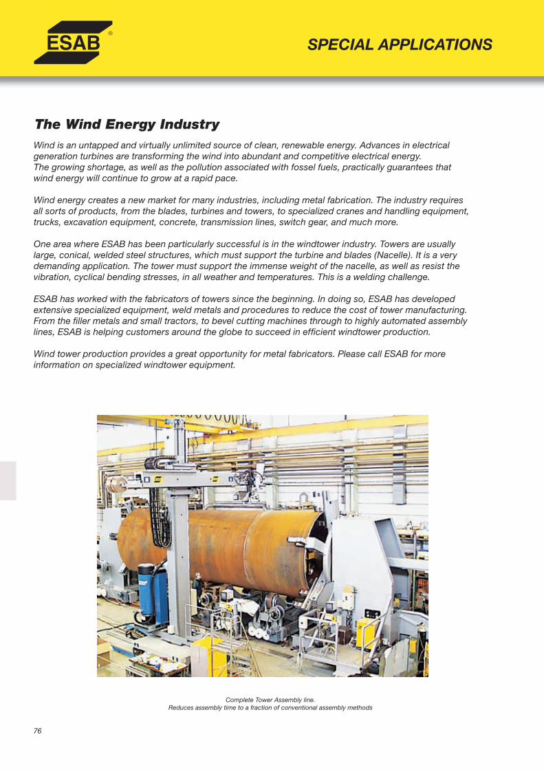
76
The Wind Energy IndustryWind is an untapped and virtually unlimited source of clean, renewable energy. Advances in electricalgeneration turbines are transforming the wind into abundant and competitive electrical energy.The growing shortage, as well as the pollution associated with fossel fuels, practically guarantees thatwind energy will continue to grow at a rapid pace.
Wind energy creates a new market for many industries, including metal fabrication. The industry requiresall sorts of products, from the blades, turbines and towers, to specialized cranes and handling equipment,trucks, excavation equipment, concrete, transmission lines, switch gear, and much more.
One area where ESAB has been particularly successful is in the windtower industry. Towers are usuallylarge, conical, welded steel structures, which must support the turbine and blades (Nacelle). It is a verydemanding application. The tower must support the immense weight of the nacelle, as well as resist thevibration, cyclical bending stresses, in all weather and temperatures. This is a welding challenge.
ESAB has worked with the fabricators of towers since the beginning. In doing so, ESAB has developedextensive specialized equipment, weld metals and procedures to reduce the cost of tower manufacturing.From the fi ller metals and small tractors, to bevel cutting machines through to highly automated assemblylines, ESAB is helping customers around the globe to succeed in effi cient windtower production.
Wind tower production provides a great opportunity for metal fabricators. Please call ESAB for moreinformation on specialized windtower equipment.
SPECIAL APPLICATIONS
Complete Tower Assembly line.Reduces assembly time to a fraction of conventional assembly methods

77Sales Literature WindTower Production Lines, order number ............ contact ESAB
The Wind Energy Industry
SPECIAL APPLICATIONS
Automated Assembly Line
Large Column and Boom Manipulators
Turning Rolls and Transport Equipment
Door Frame Welder
• Extensive variety of turning rolls customized forheavy windtower sections
• Transfer carriages on bogies• Fit-up, transport and paint rolls
• Unique, multiaxis robot, drastically reducesweld time, while improving quality. Availablefor a variety of door designs
• Based on the Railtrac Flexible Automationsystem, control offers programmable beadshape, oscillation, and full control over ESABsemi-automatic welder
• Operator can easily modify program on the fl yto allow for changing fi tup of the joint
• Uses A6 subarc weld heads and PEHmicroprocessor controller
• High deposition rates can be achieved withoptions such as twin wire, synergic cold wire, fl ux feed and recovery, and large wire reels
• Operator controls process from fl oor heightplatform, through seam tracking and video cameras
• Can be equipped with tandem wire process for higher production in thick sections
• Unique Head and Tailstock sytem, capacity 80 ton, up to 6.1 m diameter. Precision clamping system ensures roundness of cans, for precision fi t-up
• Special fi t-up jig allows operator effortlessalignment adjustment
• Turning rolls and transport equipment, adapted for conical towers
• System reduces assembly time to a fraction ofconventional assembly

78
CaB Based Beam Welders
Aluminum Trailer Beam Welder, With Narrow Precision Track
Submerged Arc Trailer Beam Welder
Walltrac Wall Mounted CaB Welding Station
Beam Welding
SPECIAL APPLICATIONS
Sales Literature Beam Welding, order number .......................contact ESAB
ESAB offers a variety of beam welding solutions from simple tractors to fully automated beam assembly lines for all styles of beams, from I-, T-, L-beams, wide fl ange beams, columns, tapered beams and non-symmetrical beams. Our extensive experience in beam welding ensure optimum straightness and productivity. Some beam welder examples are shown, please call for further information on specifi c applications.
• Weld a large variety of beams with various confi gurations of standard columns and booms
• Processes include: subarc, tandem subarc, MIG, cored wire, and aluminum welding
• PEH integrated process controller• A2/A6 heads• Seam tracking options can be modifi ed for curved shapes,
such as trailer beams
• Pivot base allows welding on both sides of track• Unique joint tracking allows proper torch alignment through the
transition curves on the beam• MIG welding process with AristoMIG 450 and includes integrated
fume extraction system
• Available similar to above but equipped A2/A6 subarc heads, PEH process control, and fl ux recovery system
• Also available for metalcore process
• For production of various beams structures, such as I/H, box beams and non symmetrical design
• Floor space is minimized with single rail/wall support• Longitudinal and transverse welding procedures• Uses A6 welding heads, PEH process control and GMD joint
tracking

79
Beam Welding
SPECIAL APPLICATIONS
Pull Through Beam Welders:Welding head is stationary and beam is pulled through the station. Parts are automatically aligned andcompressed, eliminating tacking. Tight fi t-up ensures high weld quality. Models available for vertical or horizontal web.
IT 2000 Web Horizontal Pull ThroughBeam Welder
IT 100, 258 and 3200 Web Vertical Pull Through Beam Welder
• Both sides of fl ange welded simultaneously• Built-in straightening device to compensate for
pullback of the fl anges• Optional induction or gas heating equipment to
ensure straight beams. Required for T beams• Complete material handling systems available• PLC controlled, uses A6 DC-AC tandem subarc
heads on each side for high speed welding
• Specs:IT 100: Web height max 1 mIT 258: Web height max 2.5 mIT 3200: Web height max 3.2 m
• Both fl anges welded simultaneously• Easy to install, no special foundation required• Place two machines in line for continuous fl ow• Infeed and outfeed conveyors available• PLC controlled, uses A6 DC-AC tandem subarc
heads on each side for high speed welding• Specs:
Flange size: 100 – 700 mm;Beam height: 246 – 2200 mm
Sales Literature Beam Welding, order number .......................contact ESAB
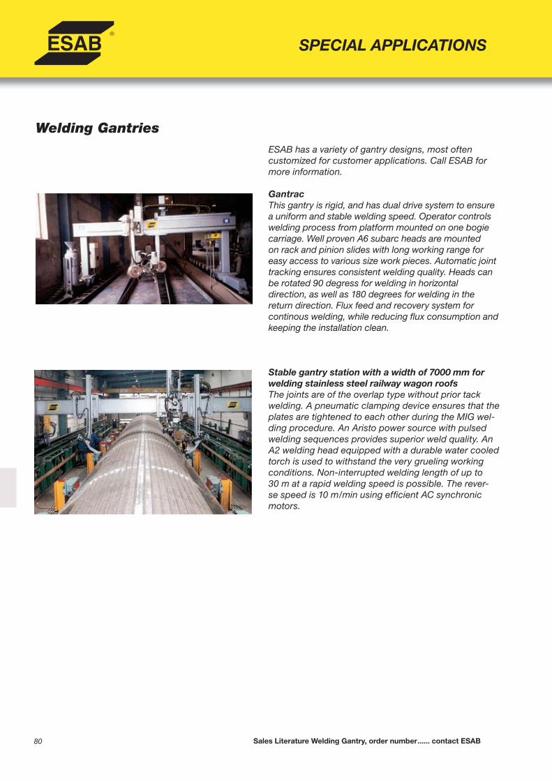
80
Welding GantriesESAB has a variety of gantry designs, most often customized for customer applications. Call ESAB for more information.
GantracThis gantry is rigid, and has dual drive system to ensure a uniform and stable welding speed. Operator controls welding process from platform mounted on one bogie carriage. Well proven A6 subarc heads are mounted on rack and pinion slides with long working range for easy access to various size work pieces. Automatic joint tracking ensures consistent welding quality. Heads can be rotated 90 degress for welding in horizontaldirection, as well as 180 degrees for welding in the return direction. Flux feed and recovery system for continous welding, while reducing fl ux consumption and keeping the installation clean.
Stable gantry station with a width of 7000 mm for welding stainless steel railway wagon roofsThe joints are of the overlap type without prior tack welding. A pneumatic clamping device ensures that the plates are tightened to each other during the MIG wel-ding procedure. An Aristo power source with pulsed welding sequences provides superior weld quality. An A2 welding head equipped with a durable water cooled torch is used to withstand the very grueling working conditions. Non-interrupted welding length of up to 30 m at a rapid welding speed is possible. The rever-se speed is 10 m/min using effi cient AC synchronic motors.
SPECIAL APPLICATIONS
Sales Literature Welding Gantry, order number ...... contact ESAB

81
SPECIAL APPLICATIONS
ESAB provides total panel line solutions for shipbuilding, from plate cutting and marking to assembly and material handling. Call for more information.
One Side Welder (OSW)One side welding improves panel assembly effi ciency by eliminating the need to rotate large panels. ESAB OSW uses vacuum clamping to securely hold plates in position during welding, without tackwelding. System uses ESAB A6 welding heads, and 3-wire subarc systems. Backing fl ux is automatically and accurately deposited on the water-cooled backup bar. Plates are fed through the OSW with infeed and outfeed tables with gripper conveyor system.
Stiffener Assembly and WeldingStiffener assembly gantry positions and welds bothsides of stiffener. Programmable stitch or continous.Gantry can carry dual stations (4 weld heads) forincreased productivity. PLC controlled, uses A2 MIGwelding components. Various designs and levels ofautomation are available.
Robot Vision TechnologyRevolutionary solution for the welding robotizedsystems programming. A photographic scan systemof the workpiece and an advanced software allow toprogram the movements of all the robot station, torchtravels and welding parameters directly on the photoof the scanned workpiece.And everything by the single “click” of the mouse.It’s dedicated to plan pieces and panels.
Shipyard Applications
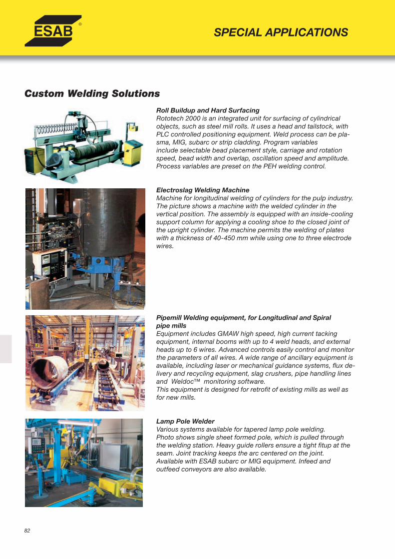
82
SPECIAL APPLICATIONS
Custom Welding Solutions
Roll Buildup and Hard SurfacingRototech 2000 is an integrated unit for surfacing of cylindrical objects, such as steel mill rolls. It uses a head and tailstock, with PLC controlled positioning equipment. Weld process can be pla-sma, MIG, subarc or strip cladding. Program variablesinclude selectable bead placement style, carriage and rotation speed, bead width and overlap, oscillation speed and amplitude. Process variables are preset on the PEH welding control.
Electroslag Welding MachineMachine for longitudinal welding of cylinders for the pulp industry. The picture shows a machine with the welded cylinder in thevertical position. The assembly is equipped with an inside-cooling support column for applying a cooling shoe to the closed joint of the upright cylinder. The machine permits the welding of plates with a thickness of 40-450 mm while using one to three electrode wires.
Pipemill Welding equipment, for Longitudinal and Spiralpipe millsEquipment includes GMAW high speed, high current tacking equipment, internal booms with up to 4 weld heads, and external heads up to 6 wires. Advanced controls easily control and monitor the parameters of all wires. A wide range of ancillary equipment is available, including laser or mechanical guidance systems, fl ux de-livery and recycling equipment, slag crushers, pipe handling lines and Weldoc™ monitoring software. This equipment is designed for retrofi t of existing mills as well as for new mills.
Lamp Pole WelderVarious systems available for tapered lamp pole welding.Photo shows single sheet formed pole, which is pulled throughthe welding station. Heavy guide rollers ensure a tight fi tup at the seam. Joint tracking keeps the arc centered on the joint.Available with ESAB subarc or MIG equipment. Infeed andoutfeed conveyors are also available.

83
Column and Boom station for welding dish ends in the chemical and petrochemical reactors marketThe weld object, which is clamped to a positioner table is tilted during the weld operation. Integrated motions between the positioner and the boom-travelling welding head allow for constant welding speeds. Station consists of NC controlled CaB 600 manipulator, 10x6 m column and boom; A6 submerged arc weldingheads, and 50 ton positioner.
Multi-head gantry stations for the energy and process marketWelding heavy winch drums intended for the ship andoffshore industry. The circumferential weld procedureutlizes twin-wire fl ux cored wire. The shell of the drum is joined at various lengths using butt joints. Simultaneously welded with two welding heads.Dimension of object: Shell diameter max 3500 mm.Length of drum max 9300 mm. Wall thickness max 80 mm.The station comprises of the following: stationary gantry with two motorized carriages (each equipped with slide assemblies and special A6 welding heads), TV monitoring system for remote control from fl oor level and turning rolls for support and weld rotation.
Column and Boom station for welding turbines in the hydropower energy marketCNC-controlled welding manipulator with sixprogrammable axes (teach in). Butt joining of the blades to the shaft of the turbine rotor. The complex 4 m longitudinal preparation is curved into three dimensions. The process is Twin-wire SAW. The working range of the manipulators is 2x4.3x2 m (HxLxW). The three remaining axes are integra-ted in the customized welding head.
Boiler Manufacturing AutomationESAB offers a complete line of boiler equipment from tube-fi n prefab machines, fi n-bar and tube-to-tube machines, to complete membrane wall panel welding and fi nishing. Membrane welders can be moveable gantry or stationary pull-through systems. Multiple head A6 subarc welding is normally used. Photo shows stationary membrane welder.
SPECIAL APPLICATIONS
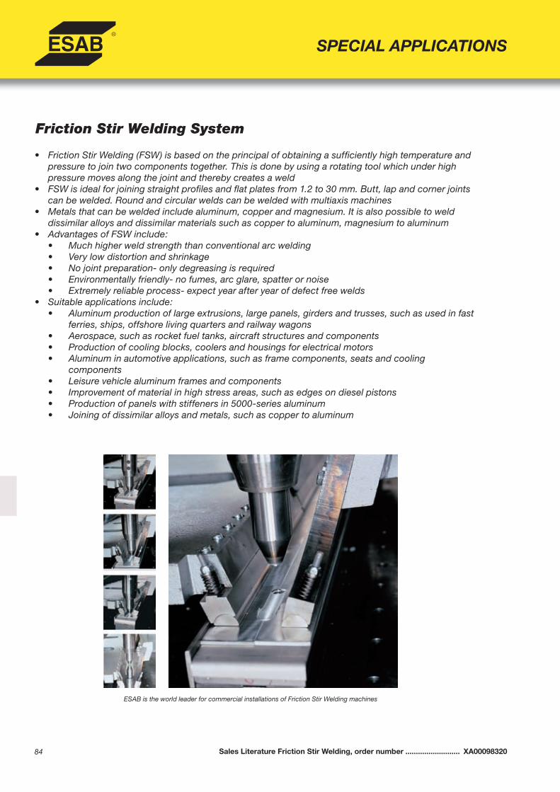
84
Friction Stir Welding System
• Friction Stir Welding (FSW) is based on the principal of obtaining a suffi ciently high temperature and pressure to join two components together. This is done by using a rotating tool which under high pressure moves along the joint and thereby creates a weld
• FSW is ideal for joining straight profi les and fl at plates from 1.2 to 30 mm. Butt, lap and corner joints can be welded. Round and circular welds can be welded with multiaxis machines
• Metals that can be welded include aluminum, copper and magnesium. It is also possible to weld dissimilar alloys and dissimilar materials such as copper to aluminum, magnesium to aluminum
• Advantages of FSW include: • Much higher weld strength than conventional arc welding • Very low distortion and shrinkage • No joint preparation- only degreasing is required • Environmentally friendly- no fumes, arc glare, spatter or noise • Extremely reliable process- expect year after year of defect free welds• Suitable applications include: • Aluminum production of large extrusions, large panels, girders and trusses, such as used in fast
ferries, ships, offshore living quarters and railway wagons • Aerospace, such as rocket fuel tanks, aircraft structures and components • Production of cooling blocks, coolers and housings for electrical motors • Aluminum in automotive applications, such as frame components, seats and cooling
components • Leisure vehicle aluminum frames and components • Improvement of material in high stress areas, such as edges on diesel pistons • Production of panels with stiffeners in 5000-series aluminum • Joining of dissimilar alloys and metals, such as copper to aluminum
SPECIAL APPLICATIONS
Sales Literature Friction Stir Welding, order number .......................... XA00098320
ESAB is the world leader for commercial installations of Friction Stir Welding machines

85
LegioTM Friction Stir Welder Super StirTM Friction Stir Welder
SPECIAL APPLICATIONS
The ESAB LEGIOTM concept combines the latesttechnology with proven quality. The modular systemmakes it possible to assemble welding stations tosuit the most varied Friction Stir Welding applications.
The LEGIOTM system consists of fi ve basic designsin a series of seven sizes, covering a welding depth of 1.2 mm to 60 mm. These basic types can besupplemented with different types of equipment to suit the most varied production needs and give maximum fl exibility to any production line.
The versatile Legio family includes linear motionwith single or dual (over /under) heads, with or withouttables. Dual axis(x – y) model is available with or without table. Tables include a hole pattern forattaching fi xtures.
Legio includes ESAB HMI control specifi cally designed for Friction Stir Welding. It is a closed loop welding control, including the ability to control the Z axis either by pressure or position. PC network connections and data transfer options are available
The ESAB SuperStirTM program includes avariety of machines developed from astandarized ESABSuperStirTM base unit and with working ranges of 0.5x1.5 m up to 10x20 m within the same concept.
The program includes customized models ofvarious designs for specifi c customer requirements in different production areas.
These different designs are used worldwide inR&D centers for joining of extrusions to panels,in production of pressure vessels as well assmall parts for the automotive and electronicindustries.
Sales Literature LEGIO, order number .............................. XA00117820Sales Literature SuperStir, order number ......................... XA00098320
LEGIOTM Modular Friction Stir Welder Installation of a SuperStir at DanStir ApS, Copenhagen, Denmark
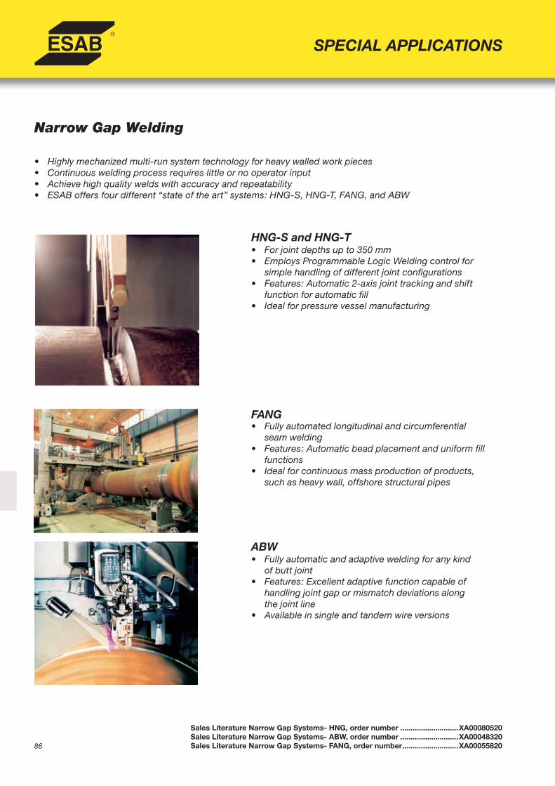
86
SPECIAL APPLICATIONS
Narrow Gap Welding
HNG-S and HNG-T
FANG
ABW
• Highly mechanized multi-run system technology for heavy walled work pieces• Continuous welding process requires little or no operator input• Achieve high quality welds with accuracy and repeatability• ESAB offers four different “state of the art” systems: HNG-S, HNG-T, FANG, and ABW
• For joint depths up to 350 mm• Employs Programmable Logic Welding control for
simple handling of different joint confi gurations• Features: Automatic 2-axis joint tracking and shift
function for automatic fi ll• Ideal for pressure vessel manufacturing
• Fully automated longitudinal and circumferential seam welding
• Features: Automatic bead placement and uniform fi ll functions
• Ideal for continuous mass production of products, such as heavy wall, offshore structural pipes
• Fully automatic and adaptive welding for any kindof butt joint
• Features: Excellent adaptive function capable ofhandling joint gap or mismatch deviations alongthe joint line
• Available in single and tandem wire versions
Sales Literature Narrow Gap Systems- HNG, order number ............................XA00080520Sales Literature Narrow Gap Systems- ABW, order number ............................XA00048320Sales Literature Narrow Gap Systems- FANG, order number ...........................XA00055820

87
Narrow Gap System- HNGFully automatic Submerged Arc Welding
• Automatic welding process based on two runs-per-layer technology
• Equipment available for both single wire (HNG-S) and tandem wire (HNG-T) applications
• Operate with joint gaps ranging from 18-24 mm for single and > 20 mm for tandem
• Welding defects such as lack of fusion, undercut, and slag entrapment are eliminated
• Produces a perfect seam shape and surface fi nish (smooth blending with side walls and excellent self-releasing action)
• Improved weld metal and heat-affected zonetoughness
• Can be integrated with ESAB’s CaB and turning roll units
• Achieve precise and accurate bead placement with two-axis joint tracking system
• System includes all required hardware, software, and programming information for automatic joint tracking and bead placement
SPECIAL APPLICATIONS
Ordering Information
Contact ESAB
Sales Literature Narrow Gap Systems- HNG, order number ......................... XA00080520Sales Literature Narrow Gap Systems- ABW, order number ......................... XA00048320Sales Literature Narrow Gap Systems- FANG, order number ........................ XA00055820
Technical DataWire dimension, mm 3-4Wire feed motor, A6-VEC 312:1Wire feed speed, m/min 4Welding current, A Max. 1x800 / 2x800Beads per layer 2Electrode angular setting Max ± 3.5 °Flux hopper capacity, litres 9.5Air consumption, Nm3/min 0.35 a 6 Kp / cm3
Working range - Slide Assembly Horizontal, mm 300Vertical, mm 420
Weight, kgHNG-S 140HNG-T 165

88
Cutting processesAlmost seventy years’ experience of cutting and responding to customers’ needs have resulted in an extensi-ve range of products to meet profi le cutting applications. Based around the four methods of oxy-fuel cutting, plasma cutting, laser cutting and water jet cutting, ESAB has developed a range of machines that deliver better cut quality, higher cutting speeds, lower operating costs and integration into automated production methods.
Oxy-CuttingOxycutting is the most commonly used process for thicker mild / low alloy steel and large dimension plates from 3 mm to 500 mm. ESAB hasunrivalled experience in this process and new improvements arecontinuously introduced.• Cooljet burner, cooling the cutting chamber while piercing and
providing longer consumable life times• Flame check control and monitoring giving all necessary information
back to the numerical control on the status of the cutting process in real time.
• The new “Cutting parameters” option within the NCE automatically adjusts all of the parameters according to the plate thickness
PlasmaThe plasma cutting process is suitable for conductive metals and produ-ces high cutting speeds in metals up to 50 mm. With larger power sources of up to 1,000 amp, stainless steel and aluminium can be cut up to 150 mm thickness. For over 40 years ESAB has pioneered the plasma techno-logy and now has many thousands of installations. The design philosophy is to go towards unmanned production with control of all cutting parame-ters from SDP fi les in the numerical control in order to:• Provide operator independent cut quality• Consistent high quality parts• Reduce need for skilled labour• Reduce set up time between different plates
LaserThe 3 kW, 4kW, 5 kW or 6 kW CO2 laser system is a very fl exible tool.The advantages are cutting up to 25 mm and marking with the same tool, high process speed, very small kerf, minimum heat distortion, very high accuracy.
CUTTING AUTOMATION
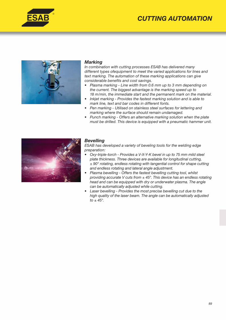
89
CUTTING AUTOMATION
MarkingIn combination with cutting processes ESAB has delivered manydifferent types ofequipment to meet the varied applications for lines and text marking. The automation of these marking applications can giveconsiderable benefi ts and cost savings.• Plasma marking - Line width from 0.6 mm up to 3 mm depending on
the current. The biggest advantage is the marking speed up to18 m/min, the immediate start and the permanent mark on the material.
• Inkjet marking - Provides the fastest marking solution and is able to mark line, text and bar codes in different fonts.
• Pen marking - Utilised on stainless steel surfaces for lettering and marking where the surface should remain undamaged.
• Punch marking - Offers an alternative marking solution when the plate must be drilled. This device is equipped with a pneumatic hammer unit.
BevellingESAB has developed a variety of beveling tools for the welding edgepreparation: • Oxy-triple-torch - Provides a V-X-Y-K bevel in up to 75 mm mild steel
plate thickness. Three devices are available for longitudinal cutting,± 90° rotating, endless rotating with tangential control for shape cutting and endless rotating and lateral angle adjustment.
• Plasma bevelling - Offers the fastest bevelling cutting tool, whilstproviding accurate V cuts from ± 45°. This device has an endless rotating head and can be equipped with dry or underwater plasma. The angle can be automatically adjusted while cutting.
• Laser bevelling - Provides the most precise bevelling cut due to thehigh quality of the laser beam. The angle can be automatically adjusted to ± 45°.
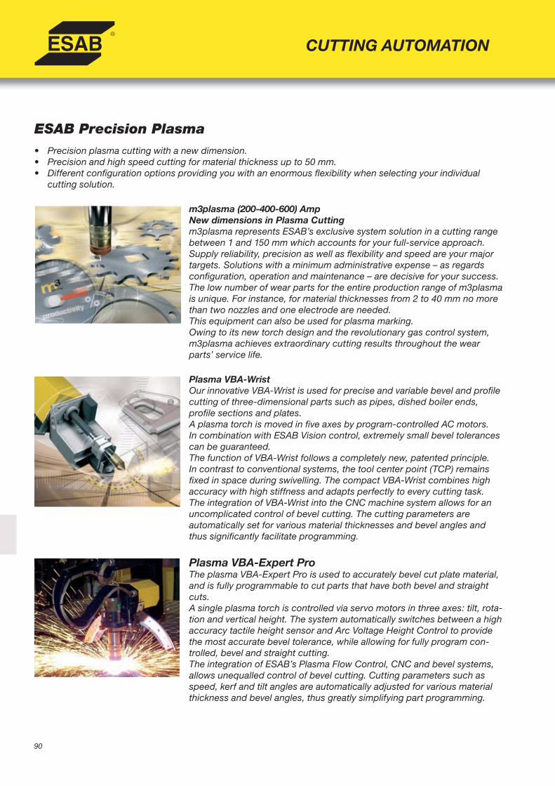
90
CUTTING AUTOMATION
ESAB Precision Plasma• Precision plasma cutting with a new dimension.• Precision and high speed cutting for material thickness up to 50 mm.• Different confi guration options providing you with an enormous fl exibility when selecting your individual
cutting solution.
m3plasma (200-400-600) AmpNew dimensions in Plasma Cuttingm3plasma represents ESAB’s exclusive system solution in a cutting range between 1 and 150 mm which accounts for your full-service approach.Supply reliability, precision as well as fl exibility and speed are your major targets. Solutions with a minimum administrative expense – as regards confi guration, operation and maintenance – are decisive for your success.The low number of wear parts for the entire production range of m3plasma is unique. For instance, for material thicknesses from 2 to 40 mm no more than two nozzles and one electrode are needed.This equipment can also be used for plasma marking.Owing to its new torch design and the revolutionary gas control system, m3plasma achieves extraordinary cutting results throughout the wear parts’ service life.
Plasma VBA-WristOur innovative VBA-Wrist is used for precise and variable bevel and profi le cutting of three-dimensional parts such as pipes, dished boiler ends,profi le sections and plates.A plasma torch is moved in fi ve axes by program-controlled AC motors.In combination with ESAB Vision control, extremely small bevel tolerances can be guaranteed.The function of VBA-Wrist follows a completely new, patented principle.In contrast to conventional systems, the tool center point (TCP) remains fi xed in space during swivelling. The compact VBA-Wrist combines highaccuracy with high stiffness and adapts perfectly to every cutting task.The integration of VBA-Wrist into the CNC machine system allows for an uncomplicated control of bevel cutting. The cutting parameters areautomatically set for various material thicknesses and bevel angles and thus signifi cantly facilitate programming.
Plasma VBA-Expert ProThe plasma VBA-Expert Pro is used to accurately bevel cut plate material, and is fully programmable to cut parts that have both bevel and straight cuts.A single plasma torch is controlled via servo motors in three axes: tilt, rota-tion and vertical height. The system automatically switches between a high accuracy tactile height sensor and Arc Voltage Height Control to provide the most accurate bevel tolerance, while allowing for fully program con-trolled, bevel and straight cutting.The integration of ESAB’s Plasma Flow Control, CNC and bevel systems, allows unequalled control of bevel cutting. Cutting parameters such as speed, kerf and tilt angles are automatically adjusted for various material thickness and bevel angles, thus greatly simplifying part programming.
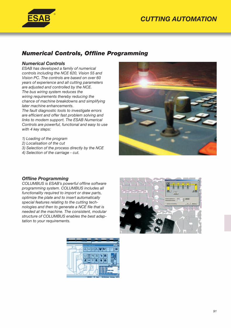
91
CUTTING AUTOMATION
Numerical Controls, Offl ine Programming
Numerical ControlsESAB has developed a family of numericalcontrols including the NCE 620, Vision 55 and Vision PC. The controls are based on over 60 years of experience and all cutting parameters are adjusted and controlled by the NCE.The bus wiring system reduces thewiring requirements thereby reducing the chance of machine breakdowns and simplifying later machine enhancements.The fault diagnostic tools to investigate errors are effi cient and offer fast problem solving and links to modem support. The ESAB Numerical Controls are powerful, functional and easy to use with 4 key steps:
1) Loading of the program2) Localisation of the cut3) Selection of the process directly by the NCE4) Selection of the carriage - cut.
Offl ine ProgrammingCOLUMBUS is ESAB’s powerful offl ine software programming system. COLUMBUS includes all functionality required to import or draw parts, optimize the plate and to insert automatically special features relating to the cutting tech-nologies and then to generate a NCE fi le that is needed at the machine. The consistent, modular structure of COLUMBUS enables the best adap-tation to your requirements.
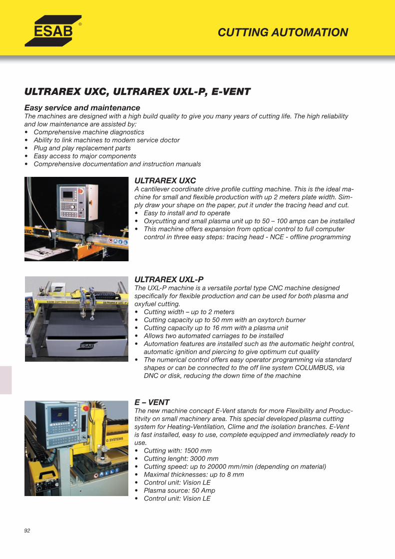
92
CUTTING AUTOMATION
ULTRAREX UXC, ULTRAREX UXL-P, E-VENT
Easy service and maintenanceThe machines are designed with a high build quality to give you many years of cutting life. The high reliability and low maintenance are assisted by:• Comprehensive machine diagnostics • Ability to link machines to modem service doctor• Plug and play replacement parts• Easy access to major components• Comprehensive documentation and instruction manuals
ULTRAREX UXCA cantilever coordinate drive profi le cutting machine. This is the ideal ma-chine for small and fl exible production with up 2 meters plate width. Sim-ply draw your shape on the paper, put it under the tracing head and cut.• Easy to install and to operate• Oxycutting and small plasma unit up to 50 – 100 amps can be installed• This machine offers expansion from optical control to full computer
control in three easy steps: tracing head - NCE - offl ine programming
ULTRAREX UXL-PThe UXL-P machine is a versatile portal type CNC machine designed specifi cally for fl exible production and can be used for both plasma and oxyfuel cutting.• Cutting width – up to 2 meters • Cutting capacity up to 50 mm with an oxytorch burner• Cutting capacity up to 16 mm with a plasma unit• Allows two automated carriages to be installed• Automation features are installed such as the automatic height control,
automatic ignition and piercing to give optimum cut quality• The numerical control offers easy operator programming via standard
shapes or can be connected to the off line system COLUMBUS, via DNC or disk, reducing the down time of the machine
E – VENTThe new machine concept E-Vent stands for more Flexibility and Produc-titvity on small machinery area. This special developed plasma cutting system for Heating-Ventilation, Clime and the isolation branches. E-Vent is fast installed, easy to use, complete equipped and immediately ready to use.• Cutting with: 1500 mm• Cutting lenght: 3000 mm• Cutting speed: up to 20000 mm/min (depending on material)• Maximal thicknesses: up to 8 mm• Control unit: Vision LE• Plasma source: 50 Amp• Control unit: Vision LE
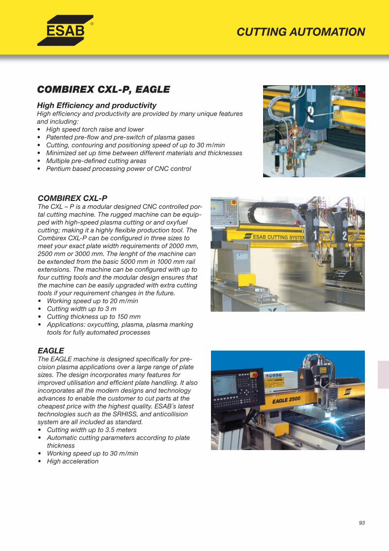
93
CUTTING AUTOMATION
COMBIREX CXL-P, EAGLE
High Effi ciency and productivityHigh effi ciency and productivity are provided by many unique features and including:• High speed torch raise and lower• Patented pre-fl ow and pre-switch of plasma gases• Cutting, contouring and positioning speed of up to 30 m/min• Minimized set up time between different materials and thicknesses• Multiple pre-defi ned cutting areas• Pentium based processing power of CNC control
COMBIREX CXL-P The CXL – P is a modular designed CNC controlled por-tal cutting machine. The rugged machine can be equip-ped with high-speed plasma cutting or and oxyfuel cutting; making it a highly fl exible production tool. The Combirex CXL-P can be confi gured in three sizes to meet your exact plate width requirements of 2000 mm, 2500 mm or 3000 mm. The lenght of the machine can be extended from the basic 5000 mm in 1000 mm rail extensions. The machine can be confi gured with up to four cutting tools and the modular design ensures that the machine can be easily upgraded with extra cutting tools if your requirement changes in the future.• Working speed up to 20 m/min• Cutting width up to 3 m• Cutting thickness up to 150 mm• Applications: oxycutting, plasma, plasma marking
tools for fully automated processes
EAGLEThe EAGLE machine is designed specifi cally for pre-cision plasma applications over a large range of plate sizes. The design incorporates many features forimproved utilisation and effi cient plate handling. It also incorporates all the modern designs and technology advances to enable the customer to cut parts at the cheapest price with the highest quality. ESAB´s latest technologies such as the SRHISS, and anticollision system are all included as standard. • Cutting width up to 3.5 meters • Automatic cutting parameters according to plate
thickness• Working speed up to 30 m/min• High acceleration
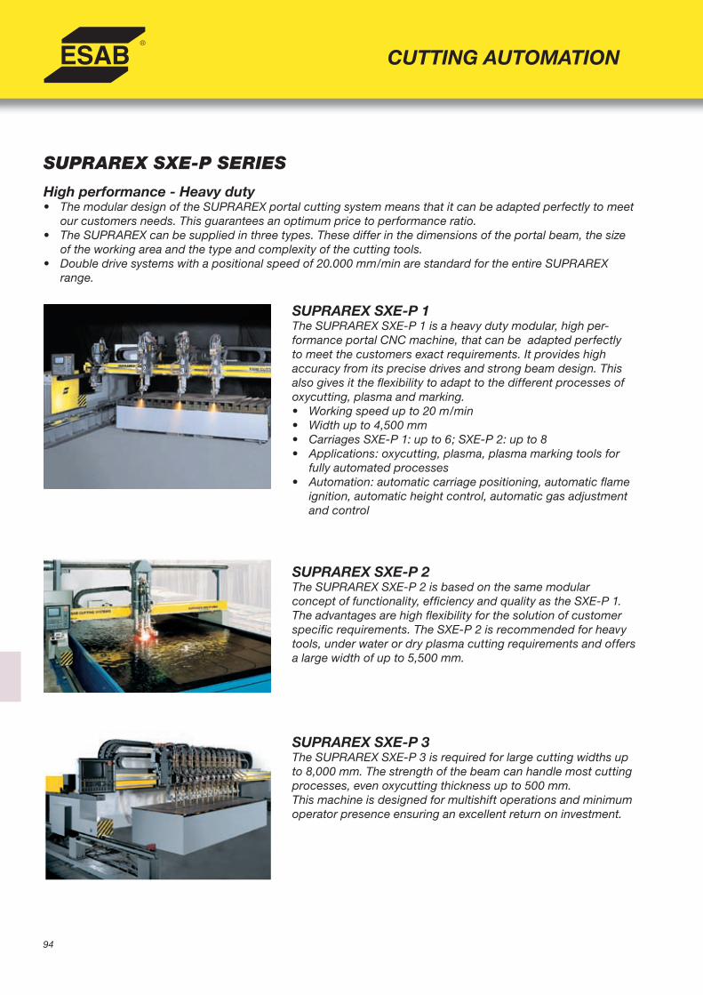
94
CUTTING AUTOMATION
SUPRAREX SXE-P SERIES
High performance - Heavy duty• The modular design of the SUPRAREX portal cutting system means that it can be adapted perfectly to meet
our customers needs. This guarantees an optimum price to performance ratio.• The SUPRAREX can be supplied in three types. These differ in the dimensions of the portal beam, the size
of the working area and the type and complexity of the cutting tools.• Double drive systems with a positional speed of 20.000 mm/min are standard for the entire SUPRAREX
range.
SUPRAREX SXE-P 1The SUPRAREX SXE-P 1 is a heavy duty modular, high per-formance portal CNC machine, that can be adapted perfectly to meet the customers exact requirements. It provides high accuracy from its precise drives and strong beam design. This also gives it the fl exibility to adapt to the different processes of oxycutting, plasma and marking.• Working speed up to 20 m/min• Width up to 4,500 mm• Carriages SXE-P 1: up to 6; SXE-P 2: up to 8• Applications: oxycutting, plasma, plasma marking tools for
fully automated processes• Automation: automatic carriage positioning, automatic fl ame
ignition, automatic height control, automatic gas adjustment and control
SUPRAREX SXE-P 2The SUPRAREX SXE-P 2 is based on the same modularconcept of functionality, effi ciency and quality as the SXE-P 1. The advantages are high fl exibility for the solution of customer specifi c requirements. The SXE-P 2 is recommended for heavy tools, under water or dry plasma cutting requirements and offers a large width of up to 5,500 mm.
SUPRAREX SXE-P 3The SUPRAREX SXE-P 3 is required for large cutting widths up to 8,000 mm. The strength of the beam can handle most cutting processes, even oxycutting thickness up to 500 mm.This machine is designed for multishift operations and minimumoperator presence ensuring an excellent return on investment.

95
CUTTING AUTOMATION
NUMOREX NXB, TELEREX TXB, ALPHAREX AXD
NUMOREX NXBThe NUMOREX is a heavy duty large portal machinedesigned to work in extreme conditions and automati-cally enable cutting and marking operations toconsistently and reliably work to the highest standards. • Working speed up to 24 m/min• Width up to 8,500 mm• Heavy tools: plasma bevelling head, oxybevelling
head with endless rotating and angle adjustment, multitool/process carriage operated automatically.
TELEREX TXBThe TELEREX portal CNC machine offers extensivescope for fl exibility with up to 32 meters in width,customized equipment and extensive carriage options.• Width up to 32.000 mm• Heavy tools• Specifi c tools: Shot blasting, grinding devices,
plasma marking units, plasma or oxycutting bevelling heads.
ALPHAREX AXD The ALPHAREX machine is a large laser machinecapable of delivering consistent laser quality on the largest plates. The resonator laser source is integrated on the top of gantry providing a cutting width of up to 5 meters and an almost unrestricted length.Specially developed straight laser cutting heads or bevelling heads enable the production of all different shapes and welding joint preparation, with the highest accuracy.

E135
EO_logo