WELDING AND ALLIED PROCESSES -...
27
MLCA STD SPEC 0740_STD {supersedes 0740_STD, 2001 Edition} WELDING AND ALLIED PROCESSES 1. SCOPE 1.1 Scope . This standard specification and appendices describe the general requirements for welding, fabrication, brazing, inspection, and associated processes on Coast Guard vessels and equipment. 1.2 Appendices . The following appendices are part of this document: PROCESS STANDARD APPENDIX Commercial Welding Standards A Welding And Inspection - Naval Sea Systems Command And Military Standards B Structural Boundary Tests And Nondestructive Inspection C 2. APPLICABLE DOCUMENTS Federal Specification (Fed Spec) BB-C-101, Jan 2004, Carbon Dioxide (CO2): Technical and USP Federal Specification (Fed Spec) QQ-B-654, Feb 1991, Brazing Alloys, Silver Federal Specification (Fed Spec) BB-H-1168, Aug 2000, Helium, Technical MIL-STD-22, Mar 1991, Welded Joint Design MIL-STD-777, Jul 2002, Schedule of Piping, Valves, Fittings, and Associated Piping Components for Naval Surface Ships MIL-STD-1627, Sep 1994, Bending of Pipe or Tube for Ship Piping Systems MIL-STD-1689, Nov 1990, Fabrication, Welding, and Inspection of Ships Structure 2004 Edition 1 0740 Downloaded from http://www.everyspec.com
Transcript of WELDING AND ALLIED PROCESSES -...

MLCA STD SPEC 0740_STD {supersedes 0740_STD, 2001 Edition}
WELDING AND ALLIED PROCESSES
1. SCOPE
1.1 Scope. This standard specification and appendices describe the general requirements for welding, fabrication, brazing, inspection, and associated processes on Coast Guard vessels and equipment.
1.2 Appendices. The following appendices are part of this document:
PROCESS STANDARD APPENDIX
Commercial Welding Standards A
Welding And Inspection - Naval Sea Systems Command And Military Standards B
Structural Boundary Tests And Nondestructive Inspection C
2. APPLICABLE DOCUMENTS
Federal Specification (Fed Spec) BB-C-101, Jan 2004, Carbon Dioxide (CO2): Technical and USP
Federal Specification (Fed Spec) QQ-B-654, Feb 1991, Brazing Alloys, Silver
Federal Specification (Fed Spec) BB-H-1168, Aug 2000, Helium, Technical
MIL-STD-22, Mar 1991, Welded Joint Design
MIL-STD-777, Jul 2002, Schedule of Piping, Valves, Fittings, and Associated Piping Components for Naval Surface Ships
MIL-STD-1627, Sep 1994, Bending of Pipe or Tube for Ship Piping Systems
MIL-STD-1689, Nov 1990, Fabrication, Welding, and Inspection of Ships Structure
2004 Edition 1 0740
Downloaded from http://www.everyspec.com
MLCA STD SPEC 0740_STD {supersedes 0740_STD, 2001 Edition}
MIL-STD-2035, May 1995, Nondestructive Testing Acceptance Criteria
MIL-A-18455, Jun 1991, Argon, Technical
Coast Guard Commandant Instruction (COMDTINST) M10360.3B, Nov 2003, Coatings and Color Manual http://isddc.dot.gov/OLPFiles/USCG/010968.pdf
Naval Sea Systems Command (NAVSEA) 0900-LP-001-7000, May 1979, Fabrication and Inspection of Brazed Piping Systems
Naval Sea Systems Command (NAVSEA) S9074-AQ-GIB-010/248, Aug 1995, Requirements for Welding and Brazing Procedure and Performance Qualification
Naval Sea Systems Command (NAVSEA) S9074-AR-GIB-010/278, Aug 1995, Requirements for Fabrication Welding and Inspection, and Casting Inspection and Repair for Machinery, Piping, and Pressure Vessels
Naval Sea Systems Command (NAVSEA) T9074-AS-GIB-010/271, Feb 1999, Requirements for Nondestructive Testing Methods
Code of Federal Regulations (CFR), Title 40, Jul 2002, Chapter I (Environmental Protection Agency), Part 63, National Emission Standards for Hazardous Air Pollutants
Code of Federal Regulations (CFR), Title 40, Jul 2002, Chapter I (Environmental Protection Agency), Part 420, Subpart L, Iron and Steel Manufacturing Hot Coating
American Bureau of Shipping (ABS), 1986, Rules for Nondestructive Inspection of Hull Welds
American Society for Nondestructive Testing (ASNT) SNT-TC-1A, 2001, Recommended Practice for Nondestructive Testing Personnel Qualification and Certification
American Society for Testing and Materials (ASTM) E94, 2000, Standard Guide for Radiographic Examination
American Society for Testing and Materials (ASTM) E114, Reapproved 2001, Standard Practice for Ultrasonic Pulse-Echo Straight-Beam Examination by the Contact Method
American Society for Testing and Materials (ASTM) E164, 2003, Standard Practice for Ultrasonic Contact Examination of Weldments
American Society for Testing and Materials (ASTM) E165, 2002,
2004 Edition 2 0740
Downloaded from http://www.everyspec.com

MLCA STD SPEC 0740_STD {supersedes 0740_STD, 2001 Edition}
Standard Test Method for Liquid Penetrant Examination
American Society for Testing and Materials (ASTM) E587, 2000, Standard Practice for Ultrasonic Angle-Beam Examination by the Contact Method
American Society for Testing and Materials (ASTM) E709, 2001, Standard Guide for Magnetic Particle Examination
American Society for Testing and Materials (ASTM) E1417, 1999, Standard Practice for Liquid Penetrant Examination
American Society for Testing and Materials (ASTM) E1444, 2001, Standard Practice for Magnetic Particle Examination
American Society for Testing and Materials (ASTM) F1076, Reapproved 1997, Standard Practice for Expanded Welded and Silver Brazed Socket Joints for Pipe and Tube
American Society of Mechanical Engineers (ASME) B31, 1998, Codes for Pressure Piping
American Society of Mechanical Engineers (ASME) B31.5, 2001, Refrigeration Piping and Heat Transfer Components
American Society of Mechanical Engineers (ASME) B32.1, Reaffirmed 1972, Preferred Thicknesses for Uncoated Thin Flat Metals
American Society of Mechanical Engineers (ASME), 1998, Boiler and Pressure Vessel Codes, Section IX, Welding and Brazing Qualifications
American Welding Society (AWS) A2.4, 1998, Standard Symbols for Welding, Brazing, and Nondestructive Examination
American Welding Society (AWS) A3.0, 2001, Standard Welding Terms and Definitions Including Terms for Adhesive Bonding, Brazing, Soldering, Thermal Cutting, and Thermal Spraying
American Welding Society (AWS) A5.8, 1992, Specification for Filler Metals for Brazing and Braze Welding
American Welding Society (AWS) A5.12/A5.12M, 1998, Specification for Tungsten and Tungsten-Alloy Electrodes for Arc Welding and Cutting
American Welding Society (AWS) B1.10, 1999, Guide for Nondestructive Examination of Welds
American Welding Society (AWS) B1.11, 2000, Guide for the Visual
2004 Edition 3 0740
Downloaded from http://www.everyspec.com

MLCA STD SPEC 0740_STD {supersedes 0740_STD, 2001 Edition}
Examination of Welds
American Welding Society (AWS) D1.1/D1.1M, 2004, Structural Welding Code - Steel
American Welding Society (AWS) D1.2/D1.2M, 2003, Structural Welding Code - Aluminum
American Welding Society (AWS) QC1, 1996, Standard for AWS Certification of Welding Inspectors
The Society for Protective Coatings (SSPC), Surface Preparation Specification No.11 (SSPC-SP 11), 2000, Power Tool Cleaning to Bare Metal
3. REQUIREMENTS
3.1 General.
3.1.1 Compliance. The Coast Guard prefers that the Contractor comply with the commercial welding requirements in Appendix A rather than the military welding requirements in Appendix B. If the Contractor wishes to weld in accordance with Appendix B of this standard, the Contractor shall obtain authorization from the KO.
3.1.2 Welding documentation. The Contractor shall provide to the Contracting Officer’s Representative (COR) copies of the following information for all intended work to be performed:
• A list of Contractor Welding Procedure Specifications (WPSs) and associated revision dates. The list shall at a minimum include all weld processes applicable to the solicitation.
• Welder qualification documentation to include the last date the welder performed the indicated process.
• When requested by the COR, supporting Procedure Qualification Records (PQRs) and full WPS documentation.
3.2 Electronic equipment protection. The Contractor shall work with the COR to safeguard electronic equipment before welding to prevent damage from stray current and electromagnetic interference. Electrically isolate or disconnect ungrounded or sensitive equipment as necessary. Locate all welder ground connections as close to the work area as possible.
3.3 Advance notice. The Contractor shall provide the COR with 24 hours advance written notice of all work planned including the
2004 Edition 4 0740
Downloaded from http://www.everyspec.com
MLCA STD SPEC 0740_STD {supersedes 0740_STD, 2001 Edition}
weld procedure to be used.
3.4 Joints. The Contractor shall ensure the following:
3.4.1 Dimensions. Joint design and fit-up dimensions are in accordance with the applicable drawings, work item or requirements of MIL-STD-22, unless otherwise indicated.
3.4.2 Welding terms and symbols. Welding terms, definitions, and symbols shall be interpreted in accordance with AWS A2.4, AWS A3.0, and ASTM F1076, as applicable.
3.5 Filler material restrictions. The Contractor shall be aware that low ductility shielded metal arc welding electrodes, including AWS classification E6010, E6012, E6013, E7014 and E7024, are not approved for joints in critical welds (see 5.1.7 (Critical welds)).
3.6 Process restrictions. The Contractor shall not use gas metal-arc welding (GMAW) utilizing short circuiting arc transfer technique for welds in ship structure above 0.25-inch material thickness, unless the process and application are specifically approved by the Contracting Officer (KO).
NOTICE!
The short circuiting arc transfer method is that in which a consumable electrode is deposited during repeated short circuits.
3.7 Surface preparation. Before welding is begun, the Contractor shall power tool clean to “bare metal” all surfaces out to one inch on both sides of existing butt or seam welds to be repaired, in accordance with SSPC-SP 11, unless otherwise directed by applicable appendix, or in a work item.
3.8 Nondestructive inspection (NDI). When inspecting welds using visual inspection (VT), liquid penetrant inspection (PT), and magnetic particle inspection (MT); the weld surface shall be clearly visible, i.e. free of paint, grease, etc.
3.9 Surface preservation. The Contractor shall prepare and coat all new and disturbed exterior and interior surfaces to match existing adjacent surfaces, in accordance with COMDTINST M10360.3B, Appendix A (Cutter and Boat Exterior Paint Systems) and Appendix B (Cutter and Boat Interior Paint Systems).
3.10 Repair of holes. Holes may be welded closed, provided the original hole diameter does not exceed 2-1/2 inches and the material thickness is 1/4 inch or greater. Holes 1/2 inch or less in diameter shall be opened to greater than 1/2 inch
2004 Edition 5 0740
Downloaded from http://www.everyspec.com

MLCA STD SPEC 0740_STD {supersedes 0740_STD, 2001 Edition}
diameter. The opening shall be shaped to 20 degrees minimum included angle before welding. Holes greater than 2-1/2 inches original diameter shall be repaired by expanding the hole size for an insert.
3.11 Zinc coatings. Metallic zinc shall be removed from all joint surfaces on which welds are to be deposited and for a distance which will be at least 1 inch from the edges of the finished welds. The localized heating technique shall not be used for removing zinc coatings from HY-80/100/130, STS or similar chemistry, or quenched and tempered low alloy high strength materials. Removal and disposal of galvanizing or zinc coatings shall comply with the requirements of 40 CFR, Chapter I (Environmental Protection Agency), Part 63 (National Emission Standards for Hazardous Air Pollutants) and Part 420, Subpart L (Iron and Steel Manufacturing Hot Coating), as well as all applicable state and local regulations regarding the testing, handling, storage, transportation, and disposal of generated hazardous wastes.
4. QUALITY ASSURANCE
4.1 Documentation. The Contractor shall submit to the COR, within 24 hours after completing the repair work, a written report, in accordance with quality assurance requirements of applicable appendix. For welding accomplished in accordance with Appendix A, adhere to quality assurance requirements of the applicable code. For welding accomplished in accordance with Appendix B, adhere to quality assurance requirements listed in the appendix.
5. NOTES
5.1 Definitions. The following definitions are applicable to this document:
5.1.1 Activity. Activity refers to all sites of an organization under the same quality assurance management and using the same quality assurance plan performing work to which this document is applicable.
5.1.2 American Welding Society (AWS). Information concerning certification of welding inspectors, welders, and accredited test facilities for AWS welder certification is available on the world wide web internet at http://www.aws.org.
2004 Edition 6 0740
Downloaded from http://www.everyspec.com

MLCA STD SPEC 0740_STD {supersedes 0740_STD, 2001 Edition}
5.1.3 Approved (approval). Approval refers to when ABS, United States Coast Guard or authorized representatives have accepted the item under consideration.
5.1.4 Applicable data sheets. Refers to welding process data sheets or welding procedure specifications approved by ABS, NCPWB established welding regulatory code and regulations or their authorized representative.
5.1.5 Authorized representative. Authorized representative is any representative specifically authorized to approve equipment, material, or procedures for the referenced regulatory agency.
5.1.6 Corrugated plate. Plate with a repetitive pattern utilizing bends in the plate as stiffeners, usually used in structural bulkheads.
5.1.7 Critical welds. Critical welds include but are not limited to welds on vessel hull plate, tank tops, structural decks and bulkheads, structural framing, and weight handling equipment.
5.1.8 Flat plate. A flat plate is considered as any plate that does not require pre-forming before installation.
5.1.9 Government inspector. Government inspector is a Government official who is charged with the responsibility for assuring that the materials, processes, fabrication techniques, inspections, tests, and testing personnel meet specification and contractual requirements. In this regard, he shall be the US Coast Guard MLCA Naval Engineering Support Unit Commanding Officer or his/her delegated representative.
5.1.10 Organization inspector. The organization inspector is the inspector of a Contractor, U.S. Coast Guard, or other agency who has been authorized by the regulatory organization to inspect and accept or reject materials and workmanship and to witness tests and validate test data.
5.1.11 Procedure qualification. A welding procedure qualification is an action by which test assemblies are prepared in accordance with a proposed procedure and evaluated either by destructive or nondestructive tests or both.
5.1.12 Qualified. The term “qualified” means that the item under consideration has been approved as required by the applicable regulatory agency or authorized representative.
2004 Edition 7 0740
Downloaded from http://www.everyspec.com

MLCA STD SPEC 0740_STD {supersedes 0740_STD, 2001 Edition}
5.1.13 Qualifier. The qualifier is an individual or test facility designated by the applicable welding regulatory agency or contractor as responsible for conducting, supervising and accepting welder qualification testing. The qualifier shall be certified by the regulatory agency as a Certified Weld Inspector (CWI) or at a minimum be a competent individual meeting all the education and experience requirements of a CWI as defined by AWS QC1.
5.1.14 Shaped plate. A shaped plate is a plate that requires mechanical or other manipulation to pre-form the shape prior to the installation procedure.
5.1.15 Sheet metal. A sheet material is any material identified by the Manufacturers' Standard Gage for Sheet Steel, a weight of 41.82 pounds per square foot per inch of thickness (e.g., 5.23 pounds per square foot per 1/8 inch of thickness), or conforming to ASME B32.1 for copper and copper base alloy flat products whose thicknesses are below 1/4 inch.
5.1.16 Shell plate. A shell plate is a plate forming the outer skin of the hull.
5.1.17 Welded studs. Welded studs include those studs attached to the structure by a welding or brazing process, designed to be a permanent part of the structure, or fasteners that are welded.
5.1.18 Welding procedure. Welding procedure is written instructions designed for use in production welding and repair welding, delineating all the essential elements and guidance to produce acceptable welds.
2004 Edition 8 0740
Downloaded from http://www.everyspec.com

MLCA STD SPEC 0740_STD {supersedes 0740_STD, 2001 Edition}
APPENDIX A
COMMERCIAL WELDING STANDARDS
10. SCOPE
10.1 Scope. This appendix contains the general requirements for welding, fabrication, brazing, inspection, and associated processes on Coast Guard vessels and equipment in accordance with commercial practices of American Welding Society (AWS), American Society of Mechanical Engineers (ASME) and American Society for Testing Materials (ASTM).
20. REQUIREMENTS
20.1 General.
20.1.1 Code selection. The Contractor shall select a commercial welding code and follow all requirements of the selected code for each welding procedure specification (WPS).
20.1.2 Mixing of code requirements. The Contractor may select different regulating codes for different weld procedures; however, all associated documentation, welding and welder requirements for each procedure (for example: the WPS, the PQR and the welder qualification and testing of the welds) must follow the same code.
20.1.3 American Bureau of Shipping (ABS) documentation. When ABS approved weld procedures and welder qualifications are to be used, the Contractor shall ensure that all weld procedures and qualifications are approved by the ABS Technical Office (located in Houston) in addition to the local surveyor. Be aware that the Coast Guard reserves the right for final approval of ABS weld procedures and welder qualifications.
20.1.4 Code compliance. The Contractor shall be aware that the Coast Guard maintains the right to review all documentation and welder performance to ensure code compliance. In the event a disagreement occurs concerning a violation of a self-regulating code (AWS or ASME), the Coast Guard will make the final decision.
20.1.5 Requirements for HY-80, HY-100, HY-130 and high-hardenable materials. The Contractor shall not use oxyfuel gas gouging for HY-80, HY-100, HY-130, and high-hardenable materials.
2004 Edition Appendix A - 1 0740
Downloaded from http://www.everyspec.com

MLCA STD SPEC 0740_STD {supersedes 0740_STD, 2001 Edition}
20.1.5.1 Use of torch heating. Torch heating for HY-80, HY-100, HY-130, and high-hardenable material shall be confined to tack or temporary welding or to those applications involving welding within a localized area. When torch heating is used for welding operations other than for tack welding, the base material shall slowly be brought up to preheat temperature with sufficient time allowed for heat to penetrate the thickness of the parts being welded. The heated area should extend approximately 6 inches beyond the weld site directions. When torches are used for low temperature (60°F to 125°F) preheating, maintain metal temperature above ambient temperature for a few minutes before welding in order to minimize condensate caused by the flame.
20.2 Welding procedures.
20.2.1 Welding procedure specification. The Contractor shall have written welding procedures that comply with their quality program for special processes and the requirements of the applicable regulatory agency code. The format of the welding procedure specification, specification test record, procedure qualification record, welder qualification test record, and nondestructive inspection of weld documents are the Contractor’s choice, but shall delineate all of the essential elements and guidance required to produce and inspect acceptable welds (see 40.1 (Commercial welding codes)). The regulating code shall be identified on each WPS.
20.2.2 Prequalified welding procedures. The Contractor shall not use welding procedures identified by AWS as “Prequalified Welding Procedure Specifications” on critical welds. For these noted critical applications, all weld procedures must be qualified by testing in accordance with the chosen regulatory code.
20.2.3 Standard weld procedures. Welding procedures identified by AWS as “Standard Welding Procedures” are authorized for use in critical weld areas without procedure re-qualification.
20.3 Welder qualification.
20.3.1 Welder performance qualification. The Contractor shall ensure that all welding and brazing is accomplished by trained welders who have been certified by the applicable regulatory code performance qualification procedures. Performance qualification procedures may be in accordance with AWS or ASME, except as noted. Additionally, welders may be certified by a second tier agency, such as the Mechanical Contractors Association of America National Certified Pipe Welding Bureau (NCPWB), if such agency maintains uniform processes, qualification and welding procedures which conform with ASME Boiler and Pressure Vessel Code Section IX, the
2004 Edition Appendix A - 2 0740
Downloaded from http://www.everyspec.com

MLCA STD SPEC 0740_STD {supersedes 0740_STD, 2001 Edition}
ASME B31 Codes for Pressure Piping, or American Welding Society standards. The Contractor must prove the welder has been actively welding using a process once every six months to maintain their qualification.
20.3.2 Method of establishing qualification. The Contractor shall ensure that each welder has satisfactorily completed a performance qualification test for the welds they are to perform. Performance qualification shall require completion of a standard test weldment in accordance with a qualified weld procedure, as well as evaluation and acceptance of the test weldment in accordance with applicable regulatory code. The following restrictions apply to welder performance qualification:
20.3.2.1 Standard test weldments shall be in accordance with all requirements of a qualified weld procedure. The welder is not allowed to make exception to any of the essential variables for welders.
20.3.2.2 Qualification by workmanship test is not authorized. Workmanship weldments are normally accepted or rejected on the basis of visual examination without radiography, bend test, bend-break test or macro-examination. This process does not provide acceptable evaluation of welder performance.
20.3.2.3 Qualification by workmanship test on a production weldment is not authorized.
20.3.2.4 Qualification of multiple welders or welding operators on one test weldment is not authorized.
20.3.2.5 Qualification by standard test is authorized on a production weld where the governing agency examination requirements permit the use of radiography in lieu of bend tests. The production weldment shall be evaluated and accepted by radiography in accordance with applicable regulatory code and requirements of this document.
20.3.2.6 The welding qualifier shall meet the requirements of paragraph 5.1.13 (Qualifier).
20.3.3 Individual qualification record (IQR). IQR certification and documentation shall be maintained by the Contractor for each welder in accordance with requirements of the certifying regulatory agency.
20.4 High strength steels. Where applicable drawings specify high strength, high tensile, special treatment steel or in particular HY material used in hull plate, structural members attached to the hull or weight handling equipment, the applicable weld data sheets or welding process specification shall be
2004 Edition Appendix A - 3 0740
Downloaded from http://www.everyspec.com

MLCA STD SPEC 0740_STD {supersedes 0740_STD, 2001 Edition}
specifically approved by the regulatory agency for the intended application and accepted by the government inspector prior to production welding. These weld processes shall meet the requirements of MIL-STD-1689.
20.5 Equipment.
20.5.1 Grounds. The Contractor shall use adjustable ground clamps that are free of defects which could damage structure or components, and shall have the ground return connection in the immediate vicinity of the work to ensure that current does not flow through bearings, pipe hangers, or other areas where arcing or high resistance paths exist. The Contractor shall use a grounding bar or lead which shall be connected directly from the machine ground return connection to the ship's hull, sized on the basis of 1,000,000 Circular Mils per 1,000 amps per 100 feet, but in no event using less than a Number One cable (85,037 Circular Mils). For vessels constructed of non-magnetic materials, the ground return cables shall be connected directly to the component being welded, as close to the weld zone as feasible.
20.5.2 Temperature-indicating crayons. Temperature crayons that contain elements such as lead, sulfur, zinc, cadmium, or mercury that could contaminate welds shall not be used.
20.6 Brazing requirements.
20.6.1 Joint design. Brazed joints shall be of the socket or sleeve type. The sleeve type fittings shall be used only where restriction prevents the use of socket type fittings for final closure joints. Fitting dimensions shall be as shown on approved drawings. Fittings for pipes and tubings larger than 0.840” O.D. shall be of the type having pre-inserted rings of brazing alloy, except the following joints may be of the face-fed type.
• Joints in freon (halocarbon) refrigerant systems. • Joints for voice tube and pneumatic tube systems. • Joints for bellmouth to pipe for tailpipes within tanks. • Face-fed fittings shall not be used in other applications
without specific approval of the COR.
20.6.2 Assembly. Assembly of joints shall be in accordance with ASTM F1076.
20.6.3 Cleaning joint after brazing. Upon completion of brazing and cooling, remove excess flux and scale from the external surfaces of the brazed joint by either washing with water or wire brushing. No filing or grinding is allowed on any portion of the joint or adjacent piping except when required for preparation of
2004 Edition Appendix A - 4 0740
Downloaded from http://www.everyspec.com

MLCA STD SPEC 0740_STD {supersedes 0740_STD, 2001 Edition}
surfaces for UT inspection.
20.6.4 Cleaning and flushing. After cooling and prior to performance of pressure or leak testing, completed piping systems shall be cleaned and flushed to the extent necessary to ensure satisfactory operation of the system and components in service. Special cleaning, when required, shall be in accordance with specified requirements in the shipbuilding, overhaul, or component specification.
20.6.5 Repair of joints.
20.6.5.1 General repair process. The brazing alloy used in the repair shall be the same grade as used in brazing the joint. The joint area at the face of the fitting shall be re-fluxed before heating for repair brazing. All repaired joints and adjacent joints where re-flowing of the brazing alloy has occurred shall be subjected to the same nondestructive tests as required for the original joint. A total of only two repair attempts are permitted on a single joint. When repairs cannot be effected after two repair attempts, the joint shall be disassembled and re-brazed.
20.6.5.2 Repairs to improve bond or align fitting. Repairs to improve percentage of bond or align a fitting may be made by re-heating and re-flowing the alloy in the joint. Joints may be repaired by rotating, adding additional flux and/or supplemental face feeding and filleting. This method is applicable to newly fabricated joints or joints which have been exposed to fresh water, cleaning solutions, refrigerant or nitrogen. No more than two repair attempts shall be made.
20.6.5.3 Repair to fix leaks or weeps. Leaks or weeps may be repaired by re-heating to re-flow the alloy in the joint and/or supplemental face feeding and filleting. This method is applicable to newly fabricated joints or joints which have been in service regardless of the fluid which the system conveyed. No more than two repair attempts shall be made.
20.6.6 Re-use of fittings and pipe.
20.6.6.1 Re-use of fittings. Fittings may be re-used subject to the limitations of ASTM F1076 and NAVSEA 0900-LP-001-7000.
20.6.6.2 Re-use of pipe. Unless otherwise specified, pipe may be re-used without inspection. Copper-nickel alloy pipe, intended for re-use shall be inspected as follows. After sizing, liquid penetrant inspect or visually inspect at 5X magnification entire periphery of pipe for length of 2D (nominal) or 2 inches (whichever is less) plus the socket depth. Cracked pipe or tubing shall not be used. If the previously brazed pipe is cut back for a distance of 2D (nominal) or 2” (whichever is less) plus the socket depth, this additional inspection is not required.
2004 Edition Appendix A - 5 0740
Downloaded from http://www.everyspec.com

MLCA STD SPEC 0740_STD {supersedes 0740_STD, 2001 Edition}
30. QUALITY ASSURANCE
No additional requirements.
40. NOTES
40.1 Commercial welding codes. Commercial welding codes offer sample welding forms that are industry accepted for documentation of welding processes and procedures. Contractors can find sample welding forms in AWS D1.1, AWS D1.2 and ASME Section IX.
2004 Edition Appendix A - 6 0740
Downloaded from http://www.everyspec.com

MLCA STD SPEC 0740_STD {supersedes 0740_STD, 2001 Edition}
APPENDIX B
WELDING AND INSPECTION NAVAL SEA SYSTEMS COMMAND AND MILITARY STANDARDS
10. SCOPE
10.1 Scope. This appendix contains the general requirements for welding, fabrication, brazing, inspection, and associated processes on Coast Guard vessels and equipment in accordance with NAVSEA S9074-AR-GIB-010/278, MIL-STD-1689, and NAVSEA 0900-LP-001-7000.
20. REQUIREMENTS
20.1 General.
20.1.1 Machinery, piping and pressure vessels. Welding and inspection for machinery, piping, pressure vessels and components shall comply with the requirements of NAVSEA S9074-AR-GIB-010/278 technical manual except as amended by this appendix.
20.1.2 Ship structure. Welding and inspection of ship structure shall comply with the requirements of MIL-STD-1689 except as amended by this appendix.
20.1.3 Brazed piping systems. Brazing and inspection for piping systems shall comply with the requirements of NAVSEA 0900-LP-001-7000 except as amended by this appendix.
20.1.4 Responsibility. The Contractor shall be responsible for submitting detailed welding procedures and processes that comply with applicable NAVSEA technical manuals or Military Standards. In addition, the Contractor shall ensure that all subcontractors have qualified procedures based on approved qualification data. Prior to production application of the welding procedures, the Contractor shall obtain approval in accordance with welding procedure qualification requirements of NAVSEA S9074-AQ-GIB-010/248. This entails submittal of the welding procedure qualification test report to the authorized NAVSEA representative for approval and submittal of the corresponding welding procedure to the authorized NAVSEA representative.
2004 Edition Appendix B - 1 0740
Downloaded from http://www.everyspec.com
MLCA STD SPEC 0740_STD {supersedes 0740_STD, 2001 Edition}
20.1.5 Welding nomenclature. All references to weld joint symbols shall be interpreted in accordance with MIL-STD-22 and AWS A2.4. Welding nomenclature and definitions shall be interpreted in accordance with AWS A3.0.
20.2 Welding procedures. Welding procedure qualifications previously prepared for other Government agencies, American Welding Society (AWS), American Bureau of Shipping (ABS), American Society of Mechanical Engineers (ASME), or other established regulatory codes may be submitted for approval to the NAVSEA authorized representative in accordance with limitations of NAVSEA S9074-AQ-GIB-010/248.
20.3 Applicable materials.
20.3.1 Base materials. Base materials shall meet the requirements of the applicable material specification listed in NAVSEA Technical Manual S9074-AR-GIB-010/278, MIL-STD-777, or MIL-STD-1689.
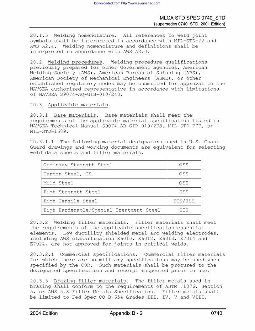
20.3.1.1 The following material designators used in U.S. Coast Guard drawings and working documents are equivalent for selecting weld data sheets and filler materials.
Ordinary Strength Steel OSS
Carbon Steel, CS OSS
Mild Steel OSS
High Strength Steel HSS
High Tensile Steel HTS/HSS
High Hardenable/Special Treatment Steel STS
20.3.2 Welding filler materials. Filler materials shall meet the requirements of the applicable specification essential elements. Low ductility shielded metal arc welding electrodes, including AWS classification E6010, E6012, E6013, E7014 and E7024, are not approved for joints in critical welds.
20.3.2.1 Commercial specifications. Commercial filler materials for which there are no military specifications may be used when specified by the COR. Such materials shall be procured to the designated specification and receipt inspected prior to use.
20.3.3 Brazing filler materials. The filler metals used in brazing shall conform to the requirements of ASTM F1076, Section 5, or AWS 5.8 Filler Metals Specification. Filler metals shall be limited to Fed Spec QQ-B-654 Grades III, IV, V and VIII.
2004 Edition Appendix B - 2 0740
Downloaded from http://www.everyspec.com

MLCA STD SPEC 0740_STD {supersedes 0740_STD, 2001 Edition}
Filler metal conforming to Fed Spec QQ-B-654 Grade III shall be limited to joining copper and copper based alloys.
20.3.4 Other materials.
20.3.4.1 Argon gas. Shall conform to the requirements of MIL-A-18455.
20.3.4.2 Helium gas. Shall conform to the requirements of Fed Spec BB-H-1168, Grade A.
20.3.4.3 Carbon dioxide. Shall conform to the requirements of Fed Spec BB-C-101.
20.3.4.4 Tungsten electrodes. Shall conform to the requirements of AWS A5.12, EWTH-2, 2% thoriated.
20.4 Welder qualification. All welder and weld operators shall be trained and performance qualified in accordance with requirements of NAVSEA S9074-AQ-GIB-010/248.
20.4.1 Individual qualification record (IQR). IQR certification and documentation shall be maintained by the Contractor for each welder in accordance with requirements of NAVSEA S9074-AQ-GIB-010/248. All records of qualification shall be made available to the government inspector prior to production welding.
20.5 Equipment.
20.5.1 Grounds. The Contractor shall use adjustable ground clamps that are free of defects which could damage structure or components, and shall have the ground return connection in the immediate vicinity of the work to ensure that current does not flow through bearings, pipe hangers, or other areas where arcing or high resistance paths exist. The Contractor shall use a grounding bar or lead which shall be connected directly from the machine ground return connection to the ship's hull, sized on the basis of 1,000,000 Circular Mils per 1,000 amps per 100 feet, but in no event using less than a Number One cable (85,037 Circular Mils). For vessels constructed of non-magnetic materials, the ground return cables shall be connected directly to the component being welded, as close to the weld zone as feasible.
20.5.2 Temperature-indicating crayons. Temperature crayons that contain elements such as lead, sulfur, zinc, cadmium, or mercury that could contaminate welds shall not be used.
2004 Edition Appendix B - 3 0740
Downloaded from http://www.everyspec.com

MLCA STD SPEC 0740_STD {supersedes 0740_STD, 2001 Edition}
20.6 Joint design and fit-up. Weld joint design and fit-up dimensions shall be in accordance with the applicable drawings, specification requirements or the authorized joint design sketch of MIL-STD-22. All brazed joint designs shall be interpreted in accordance with NAVSEA 0900-LP-001-7000 except as detailed below.
20.6.1 Brazed joint requirements. All new or replaced pipe and tube bends shall conform to MIL-STD-1627, and brazed joints shall be of the socket or sleeve types. The sleeve type fittings shall be used only where restriction prevents the use of socket type fittings or for final closure joints. Fittings for pipes and tube larger than 0.840” O.D. shall be of the type having pre-inserted rings of brazing alloy, except the following joints may be of the face-fed type.
• Joints in freon (halocarbon) refrigerant systems. • Joints for voice tube and pneumatic tube systems. • Joints for bellmouth to pipe for tailpipes within tanks. • Face-fed fittings shall not be used in other applications
without specific approval of the COR.
20.6.2 Brazed joint restrictions. All heating for torch brazing shall be accomplished with an oxyfuel gas. No brazing shall be performed on non-ferrous piping greater than 4 inches NPS or on piping systems with wall thicknesses of 0.250 inch or greater without written Coast Guard Naval engineering approval.
20.7 Joining requirements.
20.7.1 General. Welding shall be performed in accordance with the NAVSEA approved data sheets. The welding parameters on the data sheets may be used for other than the designated joint designs when specified by NAVSEA or cognizant Coast Guard engineering.
20.7.2 Process restrictions. Gas metal-arc welding (GMAW) utilizing short circuiting arc transfer technique (the consumable electrode is deposited during repeated short circuits) shall not be used for welds in surface ship structure, unless the process and application are specifically approved by NAVSEA and the Coast Guard KO.
20.7.3 Joint preparation. In addition to weld buildup to correct oversize root openings, weld buildup may be used on surfaces or edges of materials in way of penetrations or connections prior to making joint fit-up. In all cases involving welding to correct excessive root opening, the joint edges shall not be joined until the oversize root opening is corrected to
2004 Edition Appendix B - 4 0740
Downloaded from http://www.everyspec.com

MLCA STD SPEC 0740_STD {supersedes 0740_STD, 2001 Edition}
within the requirements of the applicable joint design.
20.7.4 Requirements for HY-80, HY-100, HY-130, and high-hardenable materials. The Contractor shall not use oxyfuel gas gouging for HY-80, HY-100, HY-130, and high-hardenable materials.
20.7.4.1 Use of torch heating. Torch heating for HY-80, HY-100, HY-130, and high-hardenable material shall be confined to tack or temporary welding or to those applications involving welding within a localized area. When torch heating is used for welding operations other than for tack welding, the base material shall slowly be brought up to preheat temperature with sufficient time allowed for heat to penetrate the thickness of the parts being welded. The heated area should extend approximately 6 inches beyond the weld site directions. When torches are used for low temperature (60°F to 125°F) preheating, maintain metal temperature above ambient temperature for a few minutes before welding in order to minimize condensate caused by the flame.
20.7.5 Removal of austenitic or nonferrous weld material. When it is necessary to make ferritic welds over areas that previously contained austenitic or nonferrous welds, ensure complete removal of the austenitic or nonferrous weld metal.
30. QUALITY ASSURANCE
30.1 General. All inspections of welded joints in machinery, piping and pressure vessels shall be performed in accordance with NAVSEA S9074-AR-GIB-010/278 except as modified in this appendix. All inspections of brazed joints shall be conducted in accordance with NAVSEA 0900-LP-001-7000 except as modified in this appendix.
30.2 Inspection requirements. Unless otherwise stated, inspections shall be performed in the final surface condition. Repairs to base materials or welds are to be inspected to the same requirements as the original base material or weld. Inspection shall be made when the material or weld is accessible for inspection to the degree necessary to confirm the joint is acceptable.
30.3 Methods. All inspections shall be as required within applicable specifications and shall be accomplished in accordance with the following procedures. Unless otherwise specified all acceptance criteria shall be in accordance with MIL-STD-2035 Class 3 acceptance standards.
• Visual Inspection (VT), NAVSEA T9074-AS-GIB-010/271. • Magnetic Particle Inspection (MT), ASTM E1444. • Liquid Penetrant Inspection (PT), ASTM E1417.
2004 Edition Appendix B - 5 0740
Downloaded from http://www.everyspec.com

MLCA STD SPEC 0740_STD {supersedes 0740_STD, 2001 Edition}
• Radiographic Inspection (RT), NAVSEA T9074-AS-GIB-010/271. • Ultrasonic Inspection (UT), NAVSEA T9074-AS-GIB-010/271.
30.4 Visual inspection. As a minimum, all welds shall be visually inspected. Welds requiring MT, PT, UT or RT shall in addition be visually inspected prior to final acceptance.
30.5 MT inspection.
30.5.1 General. Inspection shall be conducted in accordance with ASTM E1444. PT inspection may be substituted for MT where MT is impractical.
30.5.2 Final inspection. Final inspection of ferritic material shall be performed after all required machining or grinding has been completed, or may be performed prior to final machining when the inspected surface is within 1/32 inch of the final surface and the MT DC continuous method is used.
30.5.3 MT inspection exceptions. MT inspection is not required for backgouged roots. Additionally, MT inspection is not required for arc strike removal site, fabrication scars, nicks or gouges prior to repair welding.
30.6 PT inspection.
30.6.1 Weight handling equipment. PT inspection shall be performed on all completed welds deposited with austenitic or nonferrous electrodes in weight-handling fittings or fixtures supporting over 1 ton, unless the fitting or fixture is proof load tested after installation. Overlay or clad welding deposited on primary hull structure with austenitic or nonferrous weld metal for corrosion-resistance applications shall be PT inspected.
30.6.2 PT inspection exception. PT inspection is not required for clad welds used for wear-resistant applications.
30.7 Report. The Contractor shall document all weld inspections in accordance with welding surveillance inspection requirements of the applicable welding specification. All records of inspections shall be submitted to the COR, within 24 hours after completing the welding work.
40. NOTES
None.
2004 Edition Appendix B - 6 0740
Downloaded from http://www.everyspec.com

MLCA STD SPEC 0740_STD {supersedes 0740_STD, 2001 Edition}
APPENDIX C
STRUCTURAL BOUNDARY TESTS AND NONDESTRUCTIVE INSPECTION
10. SCOPE
10.1 Scope. This appendix describes the requirements for structural boundary testing and nondestructive inspection (NDI) on Coast Guard vessels and equipment.
20. REQUIREMENTS
20.1 Structural boundary testing.
20.1.1 Air test.
20.1.1.1 Precaution. Place a sign on each access of the space to be tested that clearly states the following phrases in upper case letters: “DANGER, DO NOT ENTER, AIR TESTING IN PROGRESS”. See 40.1 (Notices).
20.1.1.2 Set-up. Install the following at the test connection:
• One vent valve.
• Two relief valves arranged in parallel and set at 15 percent above test pressure.
• Two independent pressure gauges, each with a range such that the test pressure is in the middle of the scale.
• An air supply of not more than 25 psig with a supply capability less than the exhaust capability of either relief valve.
20.1.1.3 Isolation. Isolate the space to be tested by blanking and/or plugging all openings including lines and vents going to and from the space.
20.1.1.4 Pressurization. Apply a two psig test pressure for 10 minutes. Observe the allowable pressure drop specified in Table 1. Hold the test pressure in the space for at least 15 minutes to allow the temperature to stabilize prior to conducting the 10 minute test.
2004 Edition Appendix C - 1 0740
Downloaded from http://www.everyspec.com

MLCA STD SPEC 0740_STD {supersedes 0740_STD, 2001 Edition}
TABLE 1. ALLOWABLE TEST PRESSURE DROP
SPACE TO BE TESTED ALLOWABLE PRESSURE DROP
Tanks, voids, cofferdams None
All others 0.1 psig
20.1.1.5 Leak detection. When the allowable test pressure drop is exceeded, the Contractor shall locate the leaks and repair as required. Retest space to Table 1 requirements.
20.1.1.6 Completion. After the air test, relieve the pressure and remove all blanks and plugs.
20.1.2 Water hose test.
20.1.2.1 Precaution. Prior to conducting a water hose test, the Contractor shall ensure all adjacent equipment is protected so no damage will occur from any spray or fluid collection.
20.1.2.2 The Contractor shall conduct a water hose test by directing fresh water against the boundary being tested. The water hose nozzle shall be no less than 1/2” in diameter and the pressure at the nozzle no less than 50 psi. The nozzle shall be within 10 feet of the structure being tested.
20.1.2.3 Acceptance criteria. Successful test shall be noted by no evidence of water on the opposite side of the structure.
20.1.3 Air hose test.
20.1.3.1 Precaution. Safety glasses shall be worn at all times.
20.1.3.2 The Contractor shall conduct an air hose test by directing an air stream against the boundary being tested in a manner most likely to disclose leaks. An air pressure of 90 psi shall be supplied through a nozzle of 3/8 inch diameter. The nozzle shall be held as close as possible to the joint or boundary being tested.
20.1.3.3 Acceptance criteria. Apply a soap solution to the opposite side of the structure to detect and locate leaks. A successful test shall be noted by no formation of bubbles in the soapy solution.
2004 Edition Appendix C - 2 0740
Downloaded from http://www.everyspec.com

MLCA STD SPEC 0740_STD {supersedes 0740_STD, 2001 Edition}
20.1.4 Chalk test.
20.1.4.1 The Contractor shall ensure the door or hatch being tested is properly adjusted prior to conducting the chalk test. Chalk the bearing surface or knife edge and close the door or hatch by normal procedures. When the door or hatch is opened, the chalk from the knife edge will have been transferred to the gasket.
20.1.4.2 Acceptance criteria. A successful test is noted by a uniform and continuous chalk mark on the door’s or hatch’s gasket (100 percent gasket contact). Irregularities or breaks in the chalk mark are cause for failure.
20.1.5 Hydrostatic test. The Contractor shall make provision to relieve pressure trapped downstream of the installed system. At least one manually actuated valve shall be provided for overpressure protection during all hydrostatic tests. At least one relief valve shall also be provided as automatic overpressure protection.
20.1.5.1 Welded piping system and pressure vessel hydrostatic tests. The Contractor shall hydrostatically test welded piping systems and pressure vessels to 135 percent of the system design operating pressure for 15 minutes, using clean, fresh water, except where specified in Table 2, with no allowable leakage or permanent deformation of pressure-containing parts.
20.1.5.2 Refrigeration system tests. The Contractor shall perform a system integrity test using a dry, inert gas, such as nitrogen or anhydrous carbon dioxide. Test piping and connections at 50% of system design operating pressure, but not more than 15 psig for R-11 refrigerant systems, 50 psig for R-114 systems, 100 psig for R-124 systems, or 75 psig for R-12, R-22, and 134a systems. Inspect all joints and connections in the system using a soap bubble solution. After leaks are repaired, and prior to initial system charging, the piping installation shall be inspected and tested in accordance with ASME B31.5.
20.1.5.3 Atmospheric system tests. The Contractor shall perform a hydrostatic water test of atmospheric and gravity systems including deck drains, plumbing drains, vents and overflow piping. Piping shall be subjected to a 10-foot minimum head of water for 15 minutes, without leakage. If the system is tested in sections, at least 10 feet of the higher section shall be retested, except the uppermost 10 feet, or less, of the system. In conjunction with the hydrostatic test, or separately, each plumbing fixture and drain shall be operated to assure unobstructed flow and traps maintain the required water seal.
2004 Edition Appendix C - 3 0740
Downloaded from http://www.everyspec.com

MLCA STD SPEC 0740_STD {supersedes 0740_STD, 2001 Edition}
20.1.5.4 Mechanical joined piping system operational tests. The Contractor shall test mechanical system joints (i.e. threaded, bolted, etc.) by performing an operational test of the piping system at the system design operating pressure for 15 minutes, using clean, fresh water, except where specified in Table 2, with no allowable leakage.
20.1.5.5 Tank hydrostatic tests. The Contractor shall hydrostatically test all feed tanks, storage tanks and similar vessels that contain only static head of the acquired liquid to a pressure of 2 psig and hold the pressure for 15 minutes. Use clean, fresh water, or dry air except where specified in Table 2, with no allowable leakage.
TABLE 2. SYSTEM TEST MEDIA
SYSTEM TEST MEDIA
Lube Oil System fluid
Hydraulic Oil System fluid
Contaminated Oil, Ballast, or Seawater Systems Seawater
20.2 Nondestructive inspection of welds.
20.2.1 Inspection methods. Inspection of welded joints shall be performed by nondestructive methods such as radiographic, ultrasonic, magnetic particle, or liquid penetrant inspection. Radiographic or ultrasonic inspection, or both, is to be used when the overall soundness of the weld cross section is to be evaluated. Magnetic particle, liquid penetrant, or other AWS welding inspection methods are to be used when investigating the outer surface of welds, or may be used as a check of intermediate weld passes. Inspection of welds shall be in accordance with general guides AWS B1.10, and AWS B1.11. Inspection shall be in accordance with the following procedures:
20.2.1.1 Visual inspection (VT). Inspection shall be in accordance with AWS B1.11 or ABS Rules for Nondestructive Inspection of Hull Welds.
20.2.1.2 Magnetic particle inspection (MT).
20.2.1.2.1 General. Inspection shall be in accordance with ASTM E709 and ASTM E1444 or ABS Rules for Nondestructive Inspection of Hull Welds. PT inspection may be substituted for MT where MT is impractical. MT inspection may be performed using wet or dry method, fluorescent or non-fluorescent particles and magnetic fields of circular or longitudinal method. No cracks are
2004 Edition Appendix C - 4 0740
Downloaded from http://www.everyspec.com

MLCA STD SPEC 0740_STD {supersedes 0740_STD, 2001 Edition}
allowed.
20.2.1.2.2 Final inspection. Final inspection of ferritic material shall be performed after all required machining or grinding has been completed, or may be performed prior to final machining when the inspected surface is within 1/32 inch of the final surface and the MT DC continuous method is used. For inspection purposes, weld surface areas designed to be covered by other structural weldments (such as areas of longitudinal butt weld surfaces under frame welds or frame or stiffener weld areas covered by intercostals) are not considered finished welds until the covering weldment has been completed.
20.2.1.3 Liquid penetrant inspection (PT). Inspection shall be in accordance with ASTM E1417 and ASTM E165 or ABS Rules for Nondestructive Inspection of Hull Welds. No cracks are allowed.
20.2.1.4 Radiographic inspection (RT). Inspection shall be in accordance with ASTM E94 or ABS Rules for Nondestructive Inspection of Hull Welds.
20.2.1.5 Ultrasonic inspection (UT). Inspection shall be in accordance with ASTM E164 or ABS Rules for Nondestructive Inspection of Hull Welds.
20.2.2 Surface preparation for NDI. Inspection of completed welds shall be accomplished after slag removal and with the weld in the final surface condition. Power driven wire brushes shall not be used on surfaces that are to be liquid penetrant inspected unless the resulting surface is removed using an approved abrasive material prior to performing the inspection.
20.2.3 Weld examinations. The following welds shall be inspected:
20.2.3.1 All welds. All welds shall be visually inspected. Inspection prior to welding shall, at a minimum, include joint preparation, fit-up, and cleanliness. In process inspections, when required, shall be in the presence of the COR.
20.2.3.2 Weight handling equipment welds. PT inspection shall be performed on all completed welds deposited with austenitic or nonferrous electrodes in weight-handling fittings or fixtures supporting over 1 ton, unless the fitting or fixture is proof load tested after installation.
20.2.3.3 Overlay or clad welding. Overlay or clad welding deposited on primary hull structure with austenitic or nonferrous weld metal for corrosion-resistance applications shall be PT inspected.
2004 Edition Appendix C - 5 0740
Downloaded from http://www.everyspec.com

MLCA STD SPEC 0740_STD {supersedes 0740_STD, 2001 Edition}
20.2.3.4 Water and oil tight welds. In addition to the visual inspection requirements, the Contractor shall perform NDI, in the presence of the Coast Guard inspector, on all welds in shell plating, decks, watertight bulkheads and oiltight bulkheads.
20.2.3.5 Fillet welds 3/8 inch size and greater. The Contractor shall accomplish a surface examination, by an appropriate NDI method in the presence of the Coast Guard Inspector, of fillet welds 3/8 inch size and greater.
20.2.3.6 Multi pass welds. For multi-pass full penetration welds, the Contractor shall examine the root pass in addition to the final surface pass by an appropriate NDI method in the presence of the Coast Guard Inspector.
20.2.3.7 Loss of preheat. If the preheat temperature drops below minimum on incomplete welded joints in or to HY-80/100/130 (1-1/8 inches and over) or high hardenable materials (1" and over) the partially completed welds shall be VT/MT inspected.
20.3 Nondestructive inspection of components. Inspection of components (plate, pin, etc.) shall be performed by nondestructive methods such as ultrasonic (UT), magnetic particle (MT), or liquid penetrant (PT) inspection. UT inspection (in accordance with ASTM E114 and ASTM E587) is to be used when the overall soundness of the component cross section is to be evaluated. MT (in accordance with ASTM E709 and ASTM E1444), PT (in accordance with ASTM E165 and ASTM E1417), or other AWS inspection methods are to be used when investigating the outer surface of components.
20.4 Inspector qualifications. All individuals performing visual or other NDI operations shall be knowledgeable concerning each of the principles and methods of inspection required on the weldment. The qualification and certification of these inspectors shall be documented through the administration of written and hand-on practical examinations as performed by one of the following methods:
20.4.1 AWS Senior Certified Welding Inspector (SCWI) or Certified Welding Inspector (CWI) program.
20.4.2 American Society for Nondestructive Testing (ASNT) Qualification and Certification of NDT Personnel, as detailed by SNT-TC-1A Table 1A, 1B, 1C or 1D. The inspector shall be at a minimum certified to the ASNT Central Certification Program (ACCP) Level II certification.
2004 Edition Appendix C - 6 0740
Downloaded from http://www.everyspec.com

MLCA STD SPEC 0740_STD {supersedes 0740_STD, 2001 Edition}
2004 Edition Appendix C - 7 0740
20.5 NDI acceptance criteria. The criteria for determining the acceptability of NDI discontinuities in welds and components shall be in accordance with MIL-STD-2035 Class 3. The criteria for determining the acceptability of NDI discontinuities in brazed joints shall be in accordance with NAVSEA 0900-LP-001-7000. The Contractor shall repair all defects.
30. QUALITY ASSURANCE
30.1 Fuel filling system. Before conducting hydrostatic testing of fuel filling systems, the Contractor shall ensure all manifold/stop valves, flow control valves, drain valves, and cross-connecting valves to other systems are properly closed. If any of these boundary valves to be closed have a pressure rating of 100 psi or less, they shall remain open to prevent disc distortion during testing. Install a blank flange downstream of the valve to provide the required test boundary.
30.2 Reports. Within 24 hours after completing the test, the Contractor shall submit a written report to the COR stating the test results and identifying the location and extent of the leaks, if any.
40. NOTES
40.1 Notices. Before compartment air testing, the Coast Guard Inspector will announce on the ship's public address system that compartment air testing is in progress in the designated space and that personnel shall stand clear.
Downloaded from http://www.everyspec.com