Welding 101. 2 Objectives Upon successful completion of this unit of study, you will be able to …...
76
Welding 101
-
Upload
spencer-jacobs -
Category
Documents
-
view
214 -
download
0
Transcript of Welding 101. 2 Objectives Upon successful completion of this unit of study, you will be able to …...

Welding 101
2
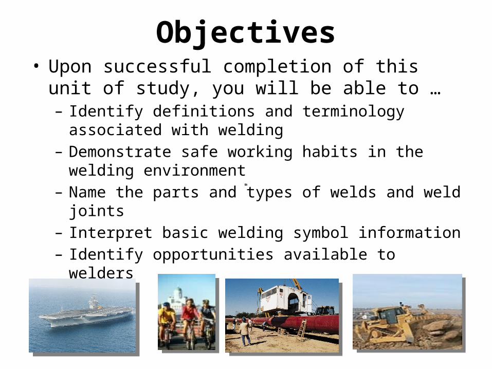
Objectives• Upon successful completion of this unit of study, you
will be able to … – Identify definitions and terminology associated with
welding– Demonstrate safe working habits in the welding
environment– Name the parts and types of welds and weld joints– Interpret basic welding symbol information – Identify opportunities available to welders

What is it?• Definition
A joining process that uses heat, pressure, and/or chemicals to fuse two materials together permanently.

4
Why Learn to Weld?
– Welding can help build a successful career so you can get the things you want in life
– Skilled welders are in demand – people use things that are welded everyday!
– Welding can be fun and safe– It is challenging and high-tech
5
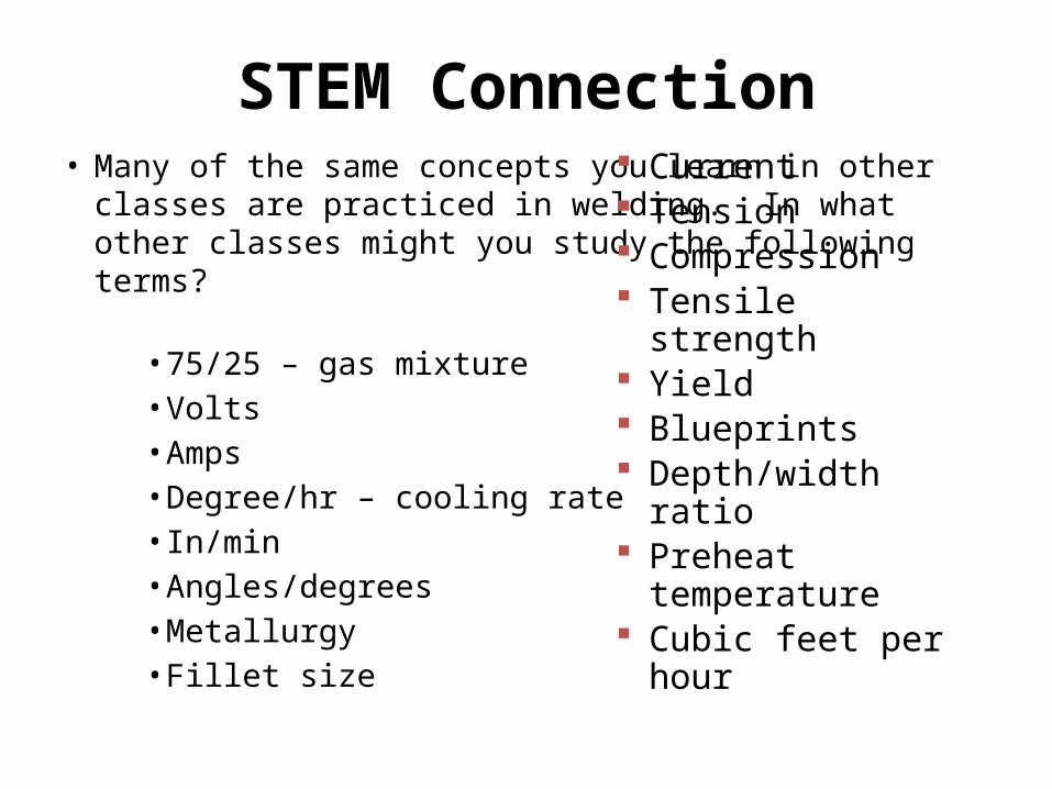
STEM Connection• Many of the same concepts you learn in other classes are
practiced in welding. In what other classes might you study the following terms?
• 75/25 – gas mixture • Volts• Amps• Degree/hr – cooling rate• In/min• Angles/degrees• Metallurgy• Fillet size
Current Tension Compression Tensile strength Yield Blueprints Depth/width ratio Preheat temperature Cubic feet per hour

6
Careers in Welding
• Engineering• Racing• Industrial Sales• Farm Repair and Fabrication• Production Welding• Military• Teaching• Maintenance
• Robotics• Ironworker/ Skilled
Trades• Auto Technician• Artist• Metal Sculpting• Owning Your Own
Business
Job opportunities in welding are changing … Welding can be valuable as a job skill or as a full-time job

How Much Money Can You Make?
• Recent statistics show that some welding jobs pay $25.00 per hour
• Local employers pay around $13-$22
• 83% of people with welding jobs were offered medical benefits- Higher than any other work
sector except government

Job Openings • http://www.indeed.com/q-Welding-l-Mani
towoc-County,-WI-jobs.html
Welder vs. Weld Operator
• Welder– One who performs a manual or semiautomatic
welding operation
• Weld Operator– One who operates adaptive control, automatic
mechanized or robotic welding equipment.
Methods of Application
• MA: Manual Welding• SA: Semiautomatic• ME: Mechanized Welding • AU: Automatic Welding

MA: Manual Welding• Welding with the torch, gun, or electrode holder held
and manipulated by hand.• Oxy-fuel welding• Gas Tungsten Arc Welding (GTAW)• Shielded Metal Arc Welding (SMAW)
• Shielded Metal Arc Welding (SMAW)
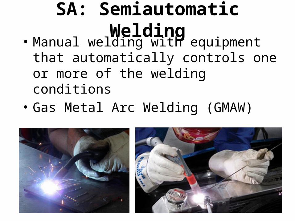
SA: Semiautomatic Welding• Manual welding with equipment that
automatically controls one or more of the welding conditions
• Gas Metal Arc Welding (GMAW)
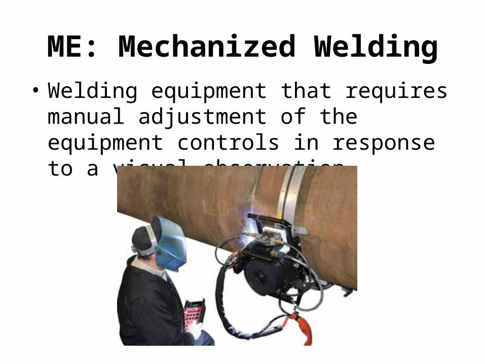
ME: Mechanized Welding• Welding equipment that requires manual
adjustment of the equipment controls in response to a visual observation.

AU: Automatic Welding
• Welding with equipment that requires only occasional or no observation and no manual adjustment of controls.
• Robots

Electrical Terms in Welding Voltage pressure, force, or push Volts
Current flow of electron Amps
Resistance hinders current flow OhmsDCEP Direct Current Electrode
PositiveDC+ Straight polarity (-) to (+)
DCEN Direct Current Electrode Negative
DC-Reverse Polarity(+) to (-)
AC Alternating current Changes polarity 120/second
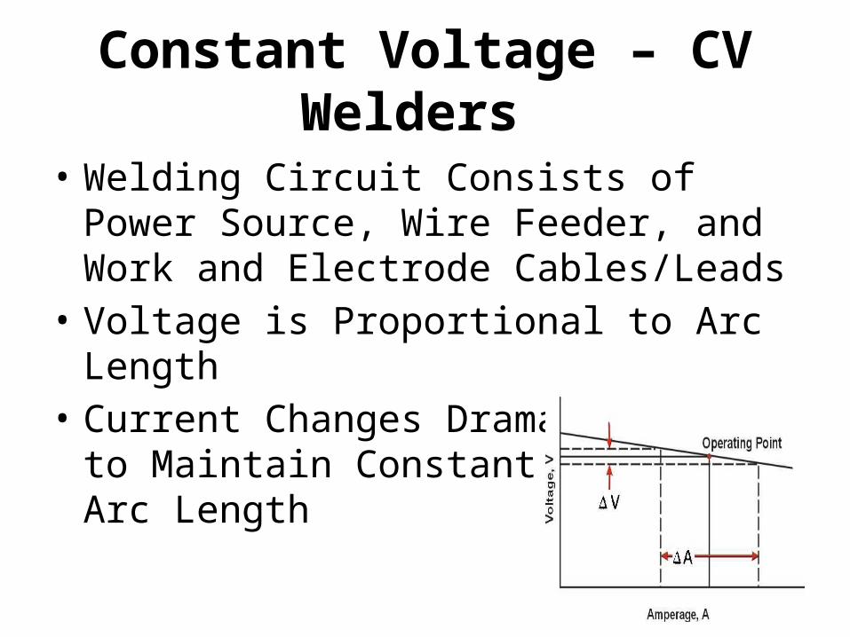
Constant Voltage – CV Welders
• Welding Circuit Consists of Power Source, Wire Feeder, and Work and Electrode Cables/Leads
• Voltage is Proportional to Arc Length• Current Changes Dramatically
to Maintain Constant Arc Length
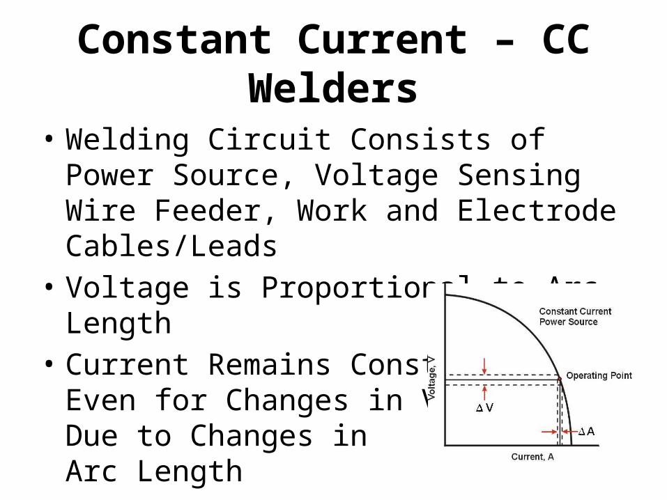
Constant Current – CC Welders
• Welding Circuit Consists of Power Source, Voltage Sensing Wire Feeder, Work and Electrode Cables/Leads
• Voltage is Proportional to Arc Length• Current Remains Constant
Even for Changes in Voltage Due to Changes in Arc Length

18
Math Terms in Welding
IPM Travel Speed = Inches per Minute Travel Speed
The speed the electrode moves along the base material
IPM Wire Feed Speed= Inches per Minute Wire Feed Speed
The speed at which the wire is fed during wire welding
Lbs/hr = Pounds per Hour Electrode deposition rate
CFH= Cubic Feet per Hour Shielding gas flow rate (wire welding)
PSI= Pounds per Square Inch Tensile strength of a material and the pressure in gas cylinders
L = Leg Fillet size measurement
% = percent Shielding gas mixture composition

PPE includes:• Hat or Beanie• #12-14 Mask• Safety Glasses• Ear Plugs• Jacket• Gloves• Jeans• Boots
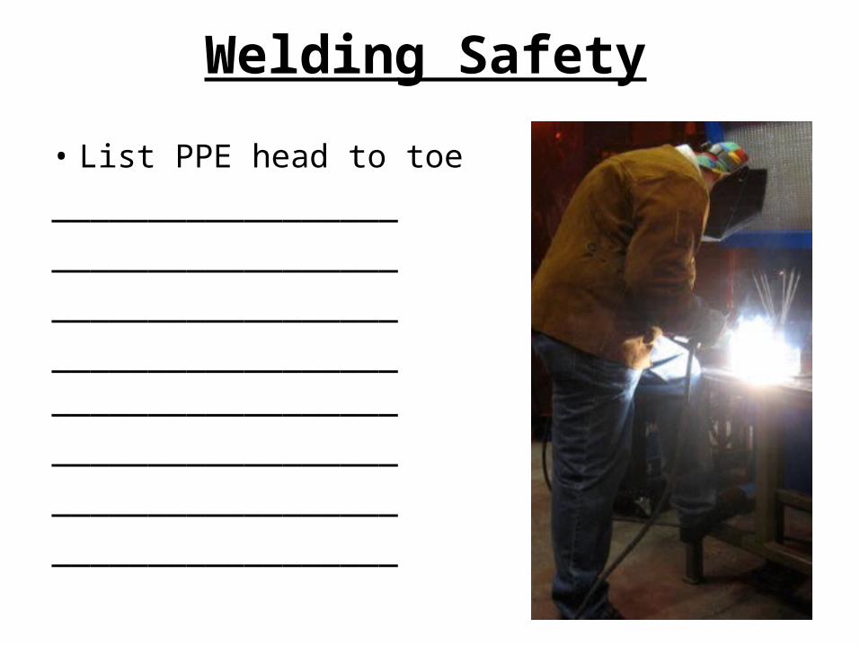
Welding Safety
• List PPE head to toe__________________ ____________________________________ ____________________________________ ____________________________________ __________________
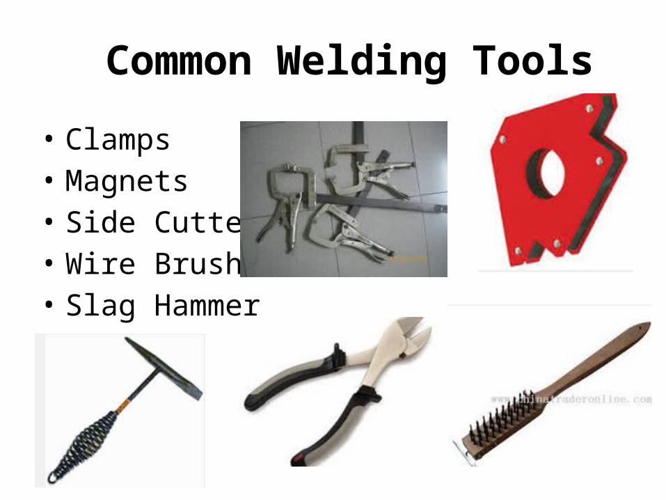
Common Welding Tools
• Clamps• Magnets • Side Cutter• Wire Brush• Slag Hammer

Metal Preparation
• A real welder takes the time!• This should take longer than the weld • Clean, clean, clean!• Joint fit-up. • Debur sharp edges• Bevel material ¼” or thicker• Preheat material ½” or thicker

23
Gauge• SHEET: measured by gauge (.0068″) to (.2391″) • PLATE: measured by inch rule (1/4” and up)
For example, steel gauge and measurement in inches:
PLEASE NOTE: As the gauge number gets smaller … the material thickness gets larger.
16 gauge = .062″ 14 gauge = .078″ 12 gauge = .105″ 10 gauge = .135″
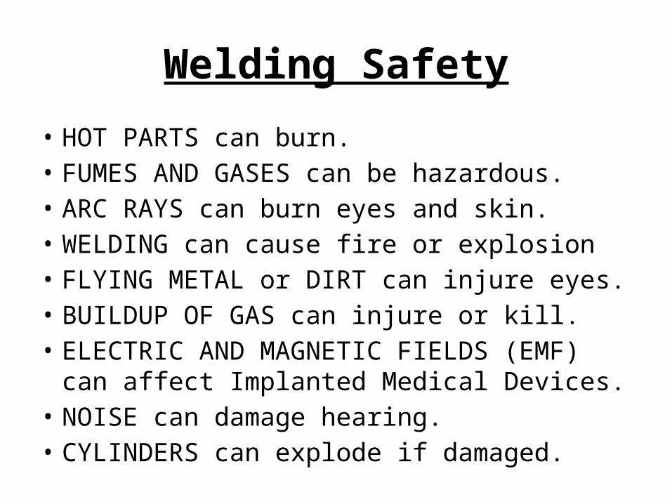
Welding Safety
• HOT PARTS can burn.• FUMES AND GASES can be hazardous.• ARC RAYS can burn eyes and skin.• WELDING can cause fire or explosion• FLYING METAL or DIRT can injure eyes.• BUILDUP OF GAS can injure or kill.• ELECTRIC AND MAGNETIC FIELDS (EMF)
can affect Implanted Medical Devices.• NOISE can damage hearing.• CYLINDERS can explode if damaged.

Welding Safety
• FIRE OR EXPLOSION hazard.• FALLING EQUIPMENT can injure.• OVERUSE can cause OVERHERATING• FLYING SPARKS can injure.• MOVING PARTS can injure.• WELDING WIRE can injure.• BATTERY EXPLOSION can injure.
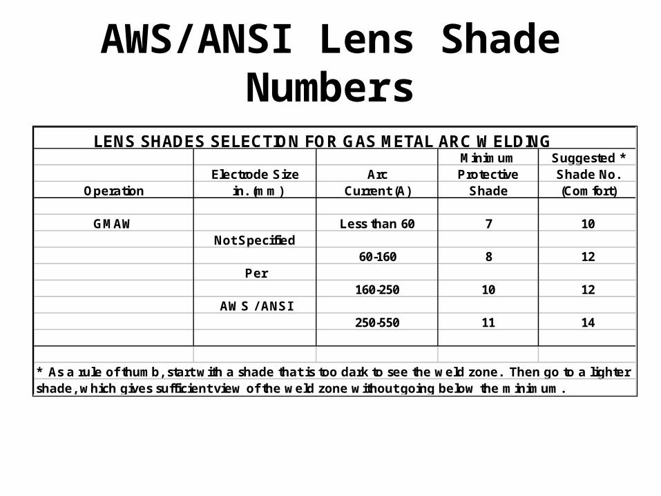
LENS SHADES SELECTION FOR GAS METAL ARC WELDINGMinimum Suggested *
Electrode Size Arc Protective Shade No.Operation in. (mm) Current (A) Shade (Comfort)
GMAW Less than 60 7 10Not Specified
60-160 8 12Per
160-250 10 12AWS / ANSI
250-550 11 14
* As a rule of thumb, start with a shade that is too dark to see the weld zone. Then go to a lightershade, which gives sufficient view of the weld zone without going below the minimum.
AWS/ANSI Lens Shade Numbers
27
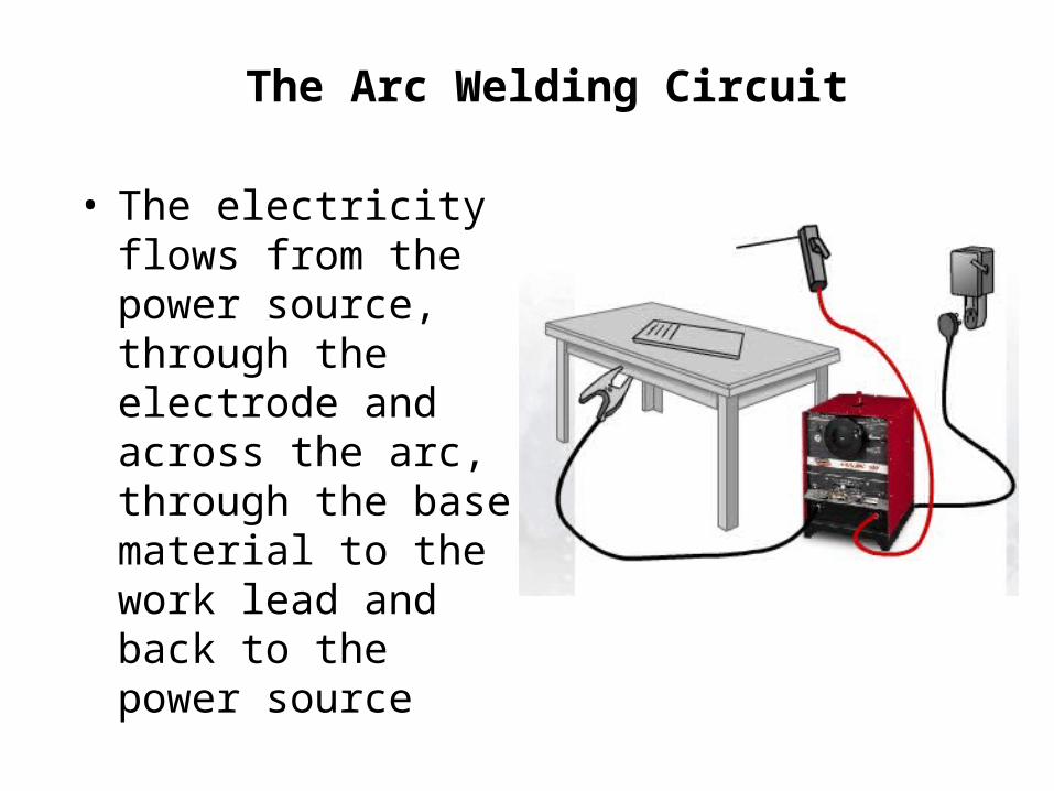
The Arc Welding Circuit
• The electricity flows from the power source, through the electrode and across the arc, through the base material to the work lead and back to the power source

Duty Cycle• “Length of time a welder can be used
continuously at its rated output in any 10 minute interval”
• Every welder has a duty cycle (60-80% common)• TRHS Lincoln V350-PRO are 60% duty cycle
– May weld 6 minutes out of a 10 minute interval– Fan kicks on and robes amperage

5 Basic Welding Joints

Welding Joints
• Can you identify theses joints?
AWS: Welding Positions
1: Flat2:Horizontal3: Vertical4: Overhead5&6: Pipe
G: Groove Weld F: Fillet Weld


Electrode Travel
• Push, Pull• Up, Down• Lead Angle• Work Angle• Travel Speed• Arc Length
IMPORTANT: Weld bead profile is affected by electrode angle, arc length, travel speed, and thickness of base metal.
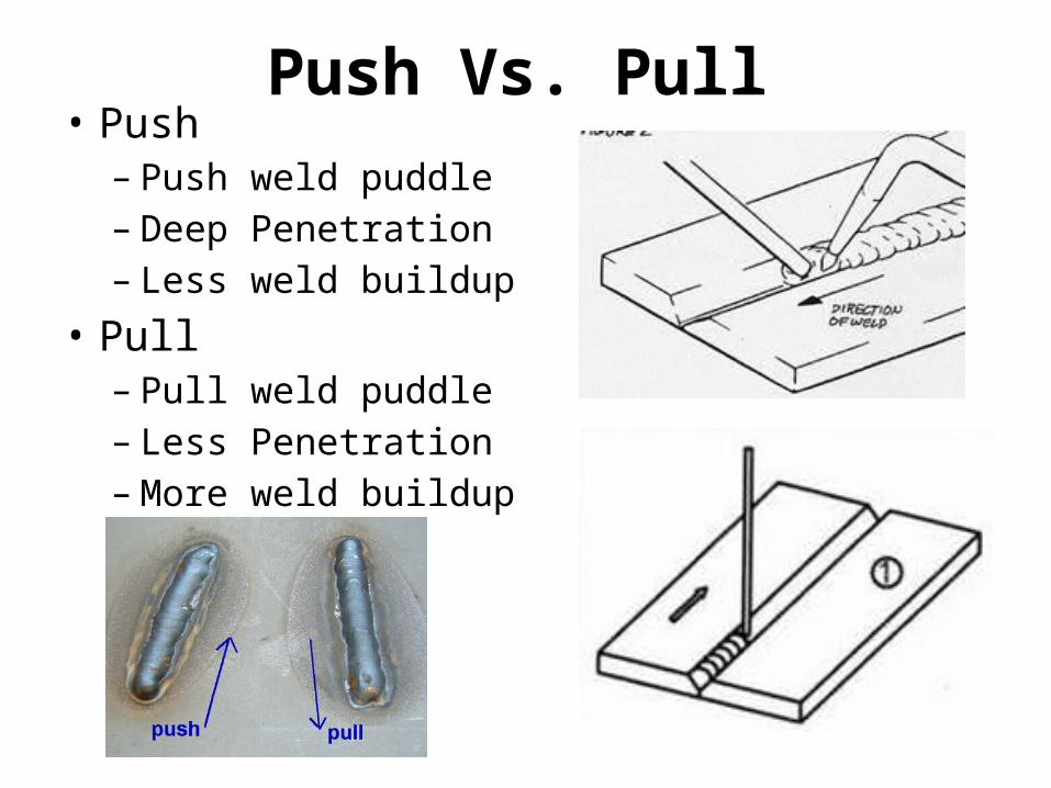
Push Vs. Pull• Push
– Push weld puddle– Deep Penetration– Less weld buildup
• Pull– Pull weld puddle– Less Penetration– More weld buildup

Up vs. Down
• Vertical down is uncommon• Heat rises making the puddle easier to control• Arc hard to see
37
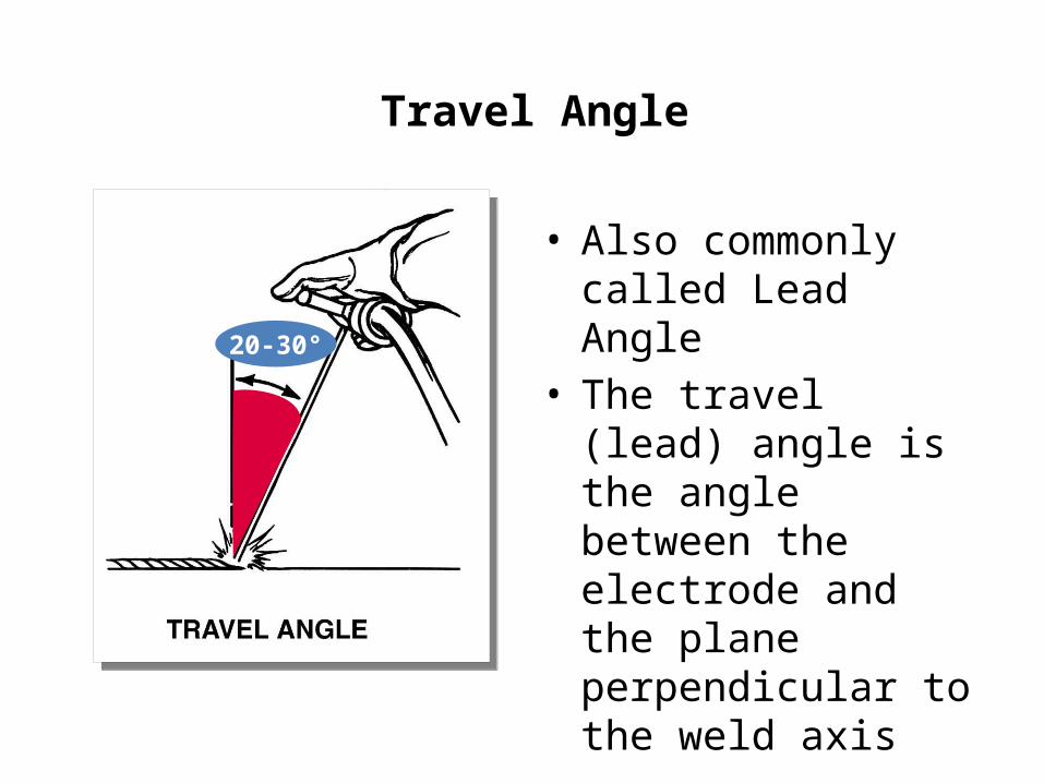
Travel Angle
• Also commonly called Lead Angle
• The travel (lead) angle is the angle between the electrode and the plane perpendicular to the weld axis
20-30°

38
Work Angle• The work angle is the
angle between the electrode and the work as depicted on the left
• Work angles can vary depending on the position the weld is being made in
90°

Work vs. Travel

Arc Length• The distance the arc stretches from the
electrode to the work-piece.• Distance varies between processes
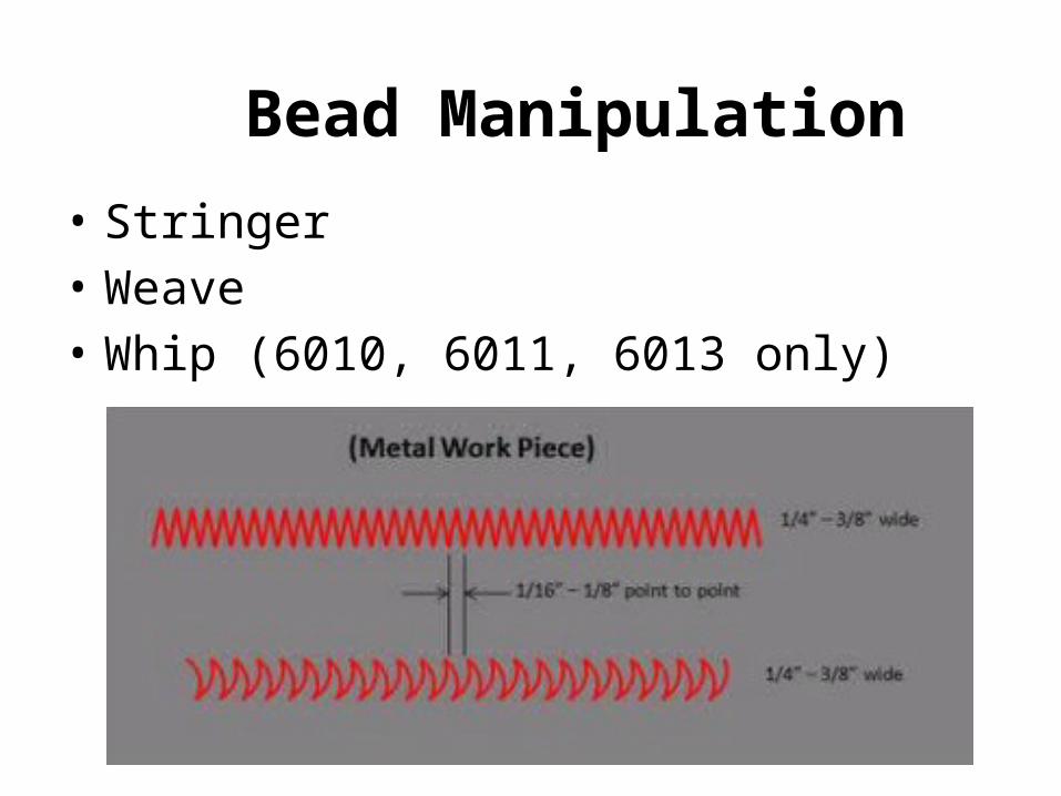
Bead Manipulation
• Stringer• Weave• Whip (6010, 6011, 6013 only)
42
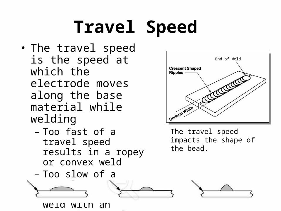
Travel Speed • The travel speed is the
speed at which the electrode moves along the base material while welding– Too fast of a travel speed
results in a ropey or convex weld
– Too slow of a travel speed results in a wide weld with an excessive metal deposit
The travel speed impacts the shape of the bead.
End of Weld

Test Your Knowledge
• Identify good, fast, slow

C.L.A.M.S
Acronym used to recall proper welding technique
• C…Current (DCEP, DCEN, AC)• L….Length of arc (Drag, 1/16, 1/8, ½”, etc.)• A…Angles (Travel angle, work angle)• M…Manipulation (Straight, weave, whip, etc.)• S…Speed of Travel (How fast you move)

Types of Welds
• Tack Weld• Intermittent (Stitch) Weld• Groove Weld • Fillet Welds• Plug or Slot Weld• Multipass Welds
– Root Pass– Hot Pass– Fill Pass– Cover Pass
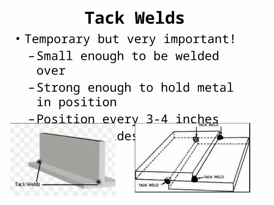
Tack Welds• Temporary but very important!
– Small enough to be welded over – Strong enough to hold metal in position– Position every 3-4 inches– Tack all sides if possible
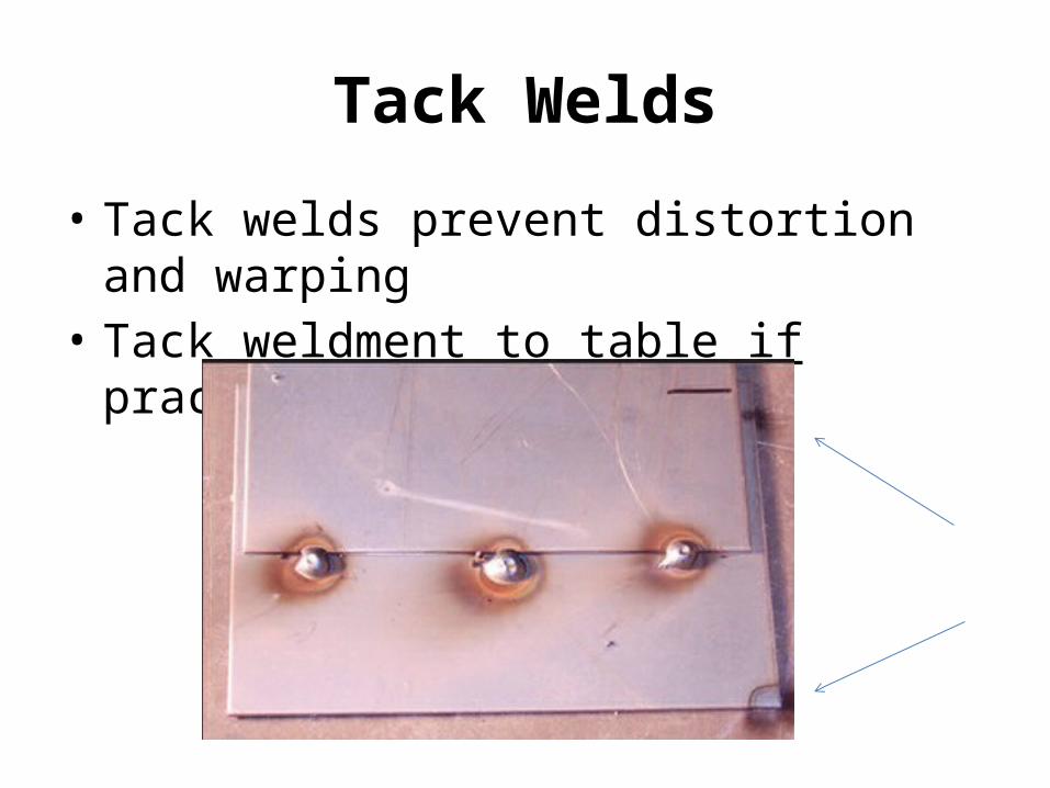
Tack Welds
• Tack welds prevent distortion and warping• Tack weldment to table if practical

Intermittent (Stitch) Welding• Welder doesn’t weld entire joint• Allows joint variation / flexibility • Lowers production cost• Reduces distortion

Grove Welds• Welding pass that deposits filler material into
base material.– Butt Joint – Face Weld
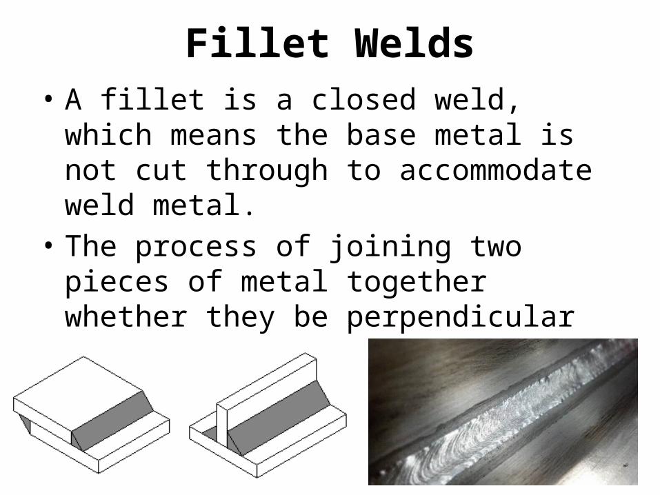
Fillet Welds• A fillet is a closed weld, which means the base
metal is not cut through to accommodate weld metal.
• The process of joining two pieces of metal together whether they be perpendicular or at an angle.

51
Fillet Weld Inspection• Fillet welds should:
– Have a flat to slightly convex face– Be uniform in appearance– Have equal leg size– Have good wash-in into base materials
• This is an example of a good fillet weld:

Plug /Slot Welds
• A circular fusion weld made in the hole of a slotted lap or tee joint

Multi-Pass Welding1. Root Pass2. Hot Pass (within 5 min.) 3. Fill Pass 4. Cover Pass 5. Cover pass6. Cover Pass
Bead Overlap should cover ~ 75% of previous pass.
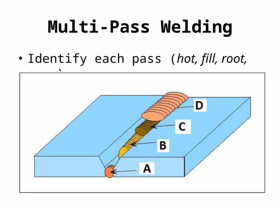
Multi-Pass Welding
• Identify each pass (hot, fill, root, cover)
Weld Bead Terminology
• Concave vs. Convex• Leg• Toe• Face• Throat• Root• Fusion Zone
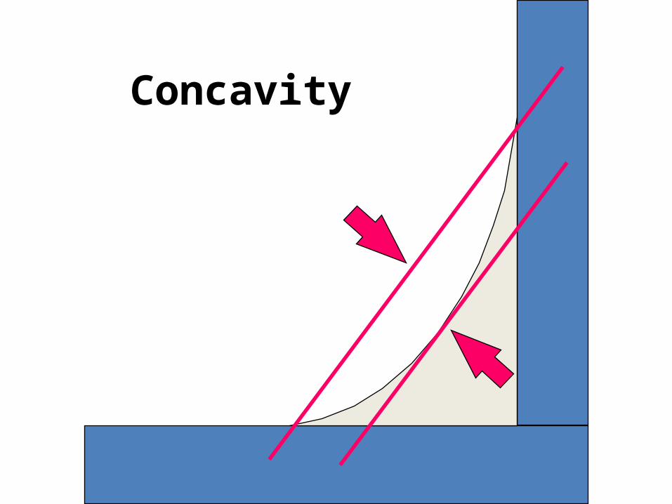
Concavity

Convexity
58
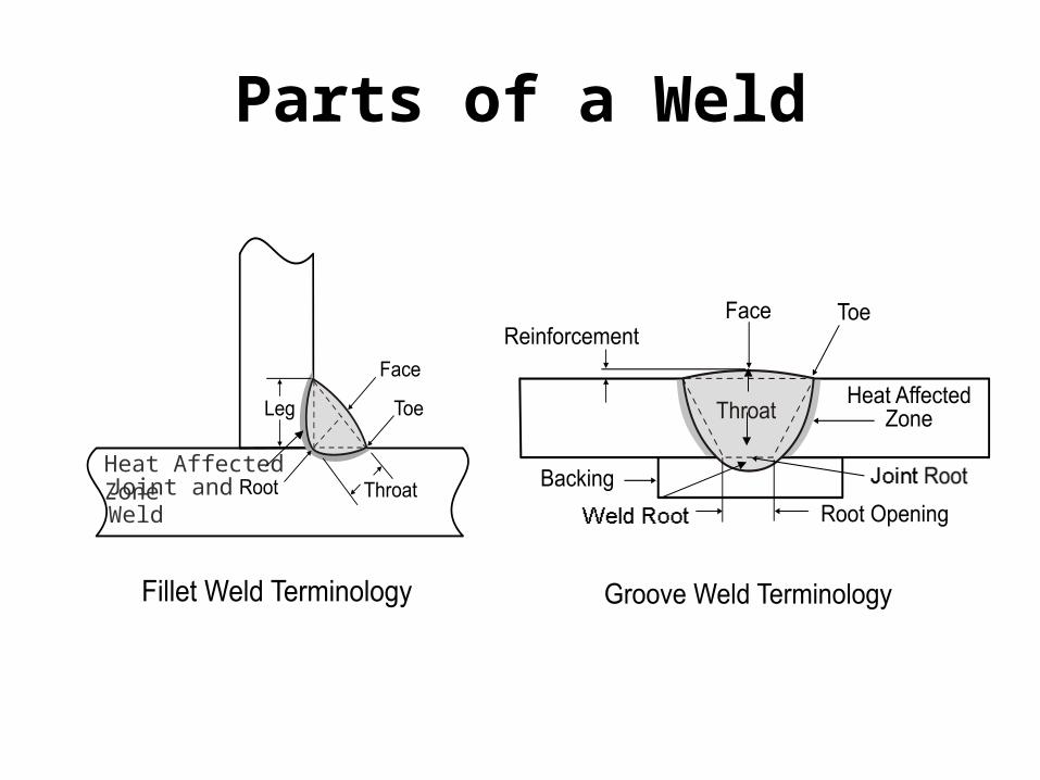
Parts of a Weld
Joint and WeldHeat Affected Zone
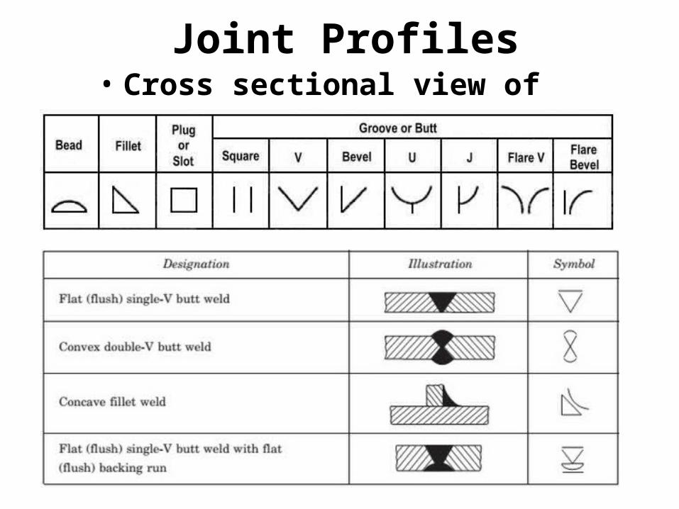
Joint Profiles• Cross sectional view of the weld
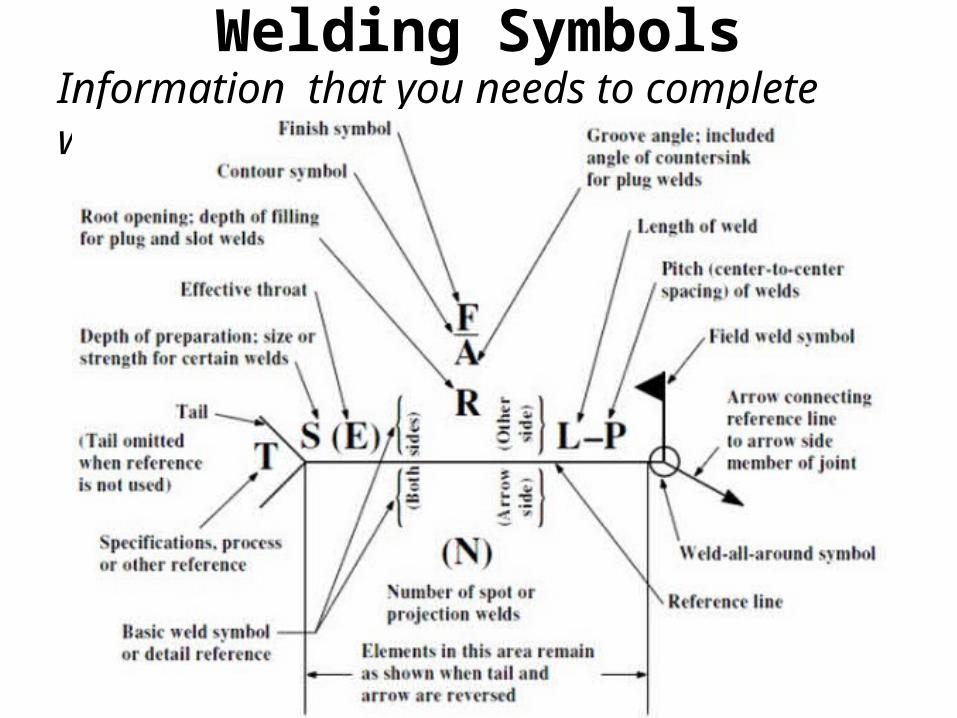
Welding SymbolsInformation that you needs to complete weld!

Weld Symbols
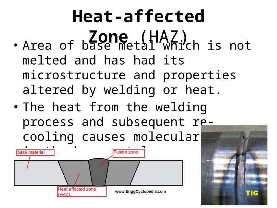
Heat-affected Zone (HAZ)• Area of base metal which is not melted and
has had its microstructure and properties altered by welding or heat.
• The heat from the welding process and subsequent re-cooling causes molecular change in the base metal.

Distortion
• Distortion: Metal expands with heat• Warping: Contracts even more as it cools• Impossible to get rid of it but able to manage it!
Controlling Distortion
• Quality tack welding• Intermittent welding• Weld little material as possible • Clamp or secure weldment to table• Alternate weld locations (front, back, front, etc)• Cool in sand or heated oven • Backstep welding
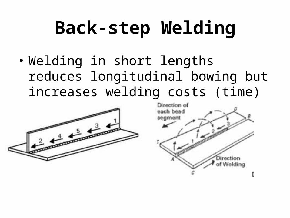
Back-step Welding
• Welding in short lengths reduces longitudinal bowing but increases welding costs (time)

Cooling Welds
• Always handle hot metal with a pliers• Assume metal is hot at all times
Sand - slowAir - mediumPurge/Quench - Fast
* Swirl figure 8 pattern

Discontinuities & Defects
• Defect– A flaw or flaws that by nature or accumulated effect
render a part or product unable to meet minimum applicable acceptance standards or specifications.
– The term designates rejectability.
• Discontinuity– An interruption of the typical structure of a material,
such as a lack of homogeneity in its mechanical, metallurgical, or physical characteristics.
– A discontinuity is not necessarily a defect!
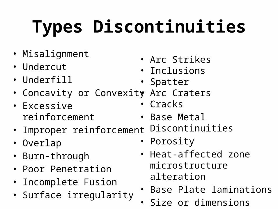
Types Discontinuities• Misalignment • Undercut• Underfill• Concavity or Convexity• Excessive reinforcement• Improper reinforcement• Overlap• Burn-through• Poor Penetration• Incomplete Fusion• Surface irregularity
• Arc Strikes• Inclusions• Spatter• Arc Craters• Cracks• Base Metal Discontinuities• Porosity• Heat-affected zone
microstructure alteration• Base Plate laminations• Size or dimensions

Visual Inspection
Knowing what discontinuities are, is the key to quality welds.
It is important for a welder to produce and confirm a proper weld!

Good Weld Characteristics

Poor Weld Characteristics

Porosity
• Single Pore• Uniformly Scattered• Cluster• Linear• Piping
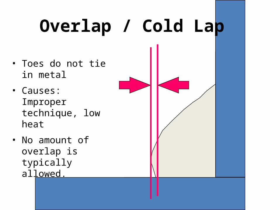
Overlap / Cold Lap
• Toes do not tie in metal
• Causes: Improper technique, low heat
• No amount of overlap is typically allowed.
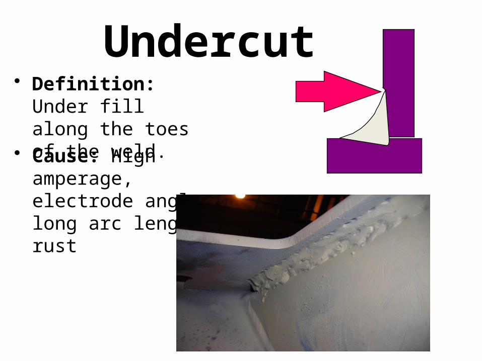
Undercut• Definition: Under fill
along the toes of the weld.
• Cause: High amperage, electrode angle, long arc length, rust

Spatter

Burn Through
• Front
• Back