Welcome to the Heidelberg JDF Tutorial. CIP4 Tutorial and Developer Sessions Sunday April 24 2005...
59
Welcome to the Welcome to the Heidelberg JDF Heidelberg JDF Tutorial Tutorial
-
Upload
emily-byrd -
Category
Documents
-
view
258 -
download
3
Transcript of Welcome to the Heidelberg JDF Tutorial. CIP4 Tutorial and Developer Sessions Sunday April 24 2005...

Welcome to the Welcome to the Heidelberg JDF Heidelberg JDF TutorialTutorial

CIP4 Tutorial and Developer Sessions
• Sunday April 24 2005• PIA/GATF
• 10.00-12.00: Tutorial• 13.00-17.00: Developer Sessions

Tutorial Session Speakers
• Henny van Esch - Optichrome
• Steve Hiebert - HP
• Rainer Prosi - Heidelberg

Outline
• Architectural Overview of JDF
• Experience with JDF

JDF on One Slide
• JDF is a Graphic Arts Job Ticket Data Interchange Format Specification - JDF is not an Application or System
• JDF is encoded in XML
• Content is referenced, not embedded
• JDF is extensible
• JDF is based on semantic structures originally defined by:– Adobe PJTF– CIP3 PPF
• JDF Job Definition + JMF Messaging +JDF Capabilities define the JDF Framework

JDF on Another Slide- Goals and Requirements -
• Why?
– Automation increases Efficiency
– Information allows for informed decisions
– We have a digital content workflow with a paper based management workflow – that is not useful!
• What?
– Describe a Job in the graphic arts from the view point of:
• Technical Applications
• Management Information Systems
• Customers
– Collect data that is relevant to a Job from origination to delivery
• How?
– See next Slides …

CIP4 Reference Model
Extended
MISExtended
MIS
Postpress
Customer Facility
Print Shop Management
Print Shop
Press
Prepress
Base
MISBase
MIS
Job Creation
Customer
PrintBuyer
Print ShopManager
PrepressOperator
PressOperator
PostpressOperator
CreativeProfessional
CreateDocument
CreateDocument
Negotiation & Quote
Sales Rep
CustomerService Rep
PrepressManager(s)
PrepressManager(s)
PressManager(s)
PressManager(s)
PrepressPrepress
PressPress
PostpressPostpress
CreateJDF Intent
CreateJDF Intent
ProductDescription
(with ranges)
PostpressManager(s)
PostpressManager(s)
ProductDescription
ProductDescription
(Actual values)
LimitedProcess
LimitedProcess
LimitedProcess
Estimating &Order Entry
Estimating &Order Entry
ProductionScheduling
ProductionScheduling

JDF Encoding
• XML Encoding
• External references via URI/URL
• XML Schema for Data Type Definitions
• Extensibility using XML name spaces

The Building Blocks of the JDF Framework
• JDF Node
– Description of a Process, Process Group or Product
• JDF Resource
– Description of a parameter set or physical entity
• JDF ResourceLink
– Link between
JDF Nodes (processes) and Resources
• JDF Capabilities Descriptions
– Limitation of a JDF interface
• JMF Messages
– Real time data interchange format

The JDF Node
• Description of a generic Process– The “Verb” in JDF– Do something at a given time– Structured container for
Scheduling and Auditing
• One JDF node type for both Products and Processes
• Less Precise Product Intentat the Job Root Node
• Abstract “ProcessGroup” Nodes or Workflow Group nodes in between
• Detailed individual or combined Processes in the Leaf Nodes
Input (Resources) Output (Resources)JDF
Node
Start End
TimeScheduling

Product Intent vs. Process Modeling
• Goal of Product Intent Description– Customers view of the “thing” they want to manufacture
– Contract Negotiation
– Process Independent
CoverCover
EndSheets
EndSheets
ReaderPages
ReaderPages
BookBook
ContentsContents

Product Intent vs. Process Modeling
• Goal of Process Modeling – Interface between MIS and Production– Process interdependencies – Manufacturing Instruction Details

Gray Boxes
• Incomplete Model of a Process• The MIS View of the process
– It’s only important if it affects the cost!– Thus, parameters not affecting costs are not
important
• Exact Process execution is potentially undefined– Ordering of steps is not necessarily predefined– Detailed Work Steps may be left out
• E.g. MIS knows RIPping, but not Trapping or ColorSpaceConversion

Audit Objects
• Logging of Job Execution– Actual times
• Start time
• End time
• Phases
• Logging of Late Changes– Resources (used 85g Paper instead of 80g)
– Consumables
• Status Summary • Event Log

Job / Customer Information
• CustomerInfo
– Map Subcontracting via Localized Customer
Information in any JDF Node
– Customer ID
– Addresses (Delivery, Invoice, …)
• NodeInfo
– Scheduling
– Deadlines
– Processing Time Estimation

JDF Node simple Example
<JDF ID=“N1" Type="Product" JobID="HDM1" JobPartID=“p1” Status=”Waiting" Version=“1.2">
<NodeInfo/>
<CustomerInfo/>
<ResourcePool>
<SomeInputResource ID="Link0002" Class="Parameter" Status=”Available"/>
<Component ID="Link0003" Class="Quantity" Status=”Unavailable" DescriptiveName="SomeOutputResource"/>
</ResourcePool>
<ResourceLinkPool>
<SomeInputResourceLink rRef="Link0002" Usage=”Input"/>
<ComponentLink rRef="Link0003" Usage=”Output"/>
</ResourceLinkPool>
<AuditPool/>
</JDF>

The JDF Node – Node Type
• Individual process types and their respective resources are defined: e.g.
– Interpreting
– Trapping
– ConventionalPrinting
– DigitalPrinting
– Cutting
– Folding
– Verification
– Delivery

Combination of JDF Nodes
• Don’t recreate a new Process Type for Permutations of known Processes!
• Create combinations of multiple defined processes into one process, e.g.:
• online finishing = printing + folding +cutting;
• in-RIP trapping = trapping + RIPping
• Three types of Combination Nodes
– Combined Node: All internal interfaces are hidden
• Smart multi-function device
– ProcessGroup: Internal nodes are accessible
• Without Sub elements (Gray Box)– MIS view
• With Sub elements– Workflow group in a department
– Subcontract

Combined vs. ProcessGroup
•Combined Node
•ProcessGroup
Combined Node
Res1ResRes
Res2
ProcessGroupRes Res
Res1 Res2

JDF Resources
• Specification of Parameters of– Product Intent description
– Logical Entities, e.g RIP Parameters, Imposition setup
– Physical Entities, e.g. Media, Devices, Plates
• Based on Adobe PJTF and CIP3 PPF– Intent Resources for product intent nodes
– Prepress : Adobe PJTF
– Press, Finishing: CIP3 PPF
• Internal to JDF or External Links to well-defined Formats – Thumbnails, Preview Files, ICC Profiles, Content Data

JDF RunList Resource Simple Example
<RunList ID="Link0003" Class="Parameter" Status=”Available“ PartIDKeys=“Run”>
<RunList Run=“1” Pages="0~10">
<LayoutElement ElementType="document"> <FileSpec URL=”File:///File1.pdf”
MimeType="application/PDF"/>
</LayoutElement>
</RunList>
<RunList Run=“2” Pages=”12~-1">
<LayoutElement ElementType="document"> <FileSpec URL=”File:///File2.pdf”
MimeType="application/PDF"/>
</LayoutElement>
</RunList>
</RunList>
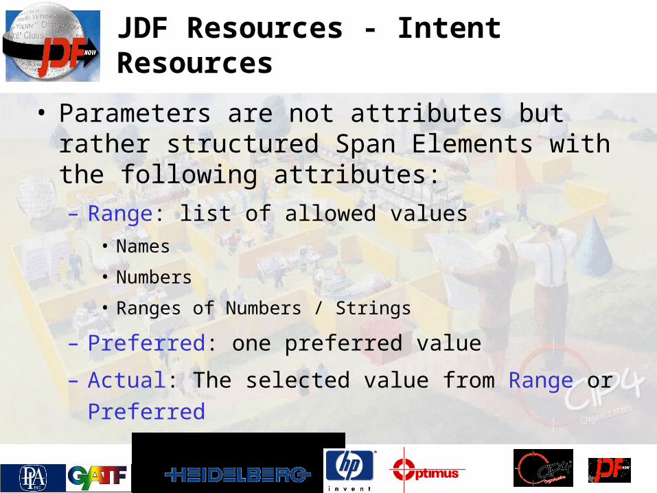
JDF Resources - Intent Resources
• Parameters are not attributes but rather structured Span Elements with the following attributes:– Range: list of allowed values
• Names
• Numbers
• Ranges of Numbers / Strings
– Preferred: one preferred value
– Actual: The selected value from Range or Preferred

JDF Resources - Details
• Special handling of multiple Parts, e.g.:– Sheets
– Separations
– Amounts
– Tiles
– Versions
• Redo one part of a large resource
– Only the yellow plate of the front surface of sheet #17
• Parallel processing of partitioned resources
• Selection of devices / operators

JDF Resources - Partitioning
• One Resource may specify multiple entities
• Multiple Partition type levels, e.g.: Sheet, Side, Separation
• Inheritance model
– specify common attributes once
– Overwrite individual attributes / elements
• Select individual or multiple parts with a ResourceLink
Partitioned Resource Common parameters
Cyan Separation parameters
Magenta Separation parameters
Yellow Separation parameters

Partitioning and Nodes
JDF Node
Ro
ot In
pu
t Reso
urce
Sh
eet=S
1S
heet=
S2
Ro
ot O
utp
ut R
esou
rce
Sh
eet=S
1S
heet=
S2
Partitioned Resources with matching partition keys are connected.
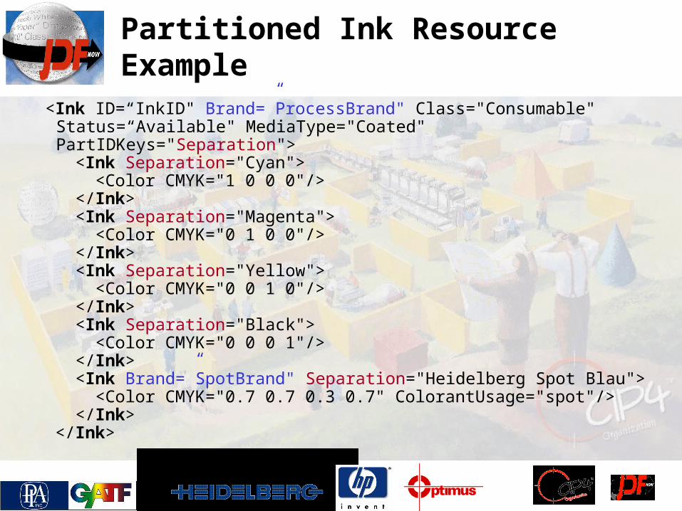
Partitioned Ink Resource Example
<Ink ID=“InkID" Brand=”ProcessBrand" Class="Consumable" Status=“Available" MediaType="Coated" PartIDKeys="Separation">
<Ink Separation="Cyan"> <Color CMYK="1 0 0 0"/> </Ink> <Ink Separation="Magenta"> <Color CMYK="0 1 0 0"/> </Ink> <Ink Separation="Yellow"> <Color CMYK="0 0 1 0"/> </Ink> <Ink Separation="Black"> <Color CMYK="0 0 0 1"/> </Ink> <Ink Brand=”SpotBrand" Separation="Heidelberg Spot
Blau"> <Color CMYK="0.7 0.7 0.3 0.7" ColorantUsage="spot"/> </Ink> </Ink>

ResourceLink
• Bind a Resource to a Node• Define Resource Usage (input or output)• Link to a Subset / Part of a Resource
– E.g. Cyan Plate of the Front of Sheet #1– Define the Amount
• Allow reuse of Resources by multiple processes– One resource may be linked
by multiple ResourceLinks
• Defines a process network
Parent Node
Child Node 1 Child Node 2
Resource 1
Link
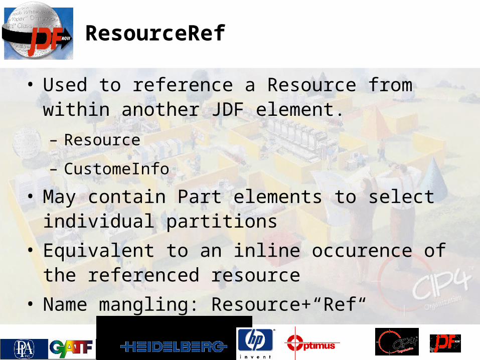
ResourceRef
• Used to reference a Resource from within another JDF element.
– Resource
– CustomeInfo
• May contain Part elements to select individual partitions
• Equivalent to an inline occurence of the referenced resource
• Name mangling: Resource+“Ref“

JDF RunList Resource Simple Example with ResourceRef
<RunList ID="Link0003" Class="Parameter" Status=”Available“ PartIDKeys=“Run”>
<RunList Run=“1” Pages="0~10">
<LayoutElementRef rRef=“L1”>
</RunList>
<RunList Run=“2” Pages=”12~-1">
<LayoutElement ElementType="document">
<FileSpec URL=”File:///File2.pdf” MimeType="application/PDF"/>
</LayoutElement>
</RunList>
</RunList>
<LayoutElement ID=“L1” ElementType="document“ Class="Parameter" Status=”Available“>
<FileSpec URL=”File:///File1.pdf” MimeType="application/PDF"/>
</LayoutElement>

ConventionalPrinting JDF Node Example
ConventionalPrinting
ExposedMedia(Plate)
Media
Ink
Resource Links
Component(including amount)
InkZoneProfile
ParametersLayout
(Control Marks)
NodeInfo•Planned StartTime•Planned EndTime
AuditPoolActual Resource UsageActual Time Summary

The JDF Node – Execution Requirements
• A Node is executable when all required input resources are available
– Serial Processing -- Standard
– Parallel Processing -- Partial Resources
– Overlapping Processing -- Pipes
– Iterative Processing -- Draft Resources
• Node dependencies allow process configuration
– A proof node can create an Approval which is needed for
the press node to operate

Node Executability
Not Executable
Not Available
Available
Available
ResourceLinks
Resource ResourceLink JDF Node

Executable
Available
Available
Available
ResourceLinks
Resource ResourceLink JDF Node
Node Executability

Not Available
Available
Available
Not Executable
Waiting
Links
Available
Available
Not Available
Links
Node ExecutabilityAnd Networks
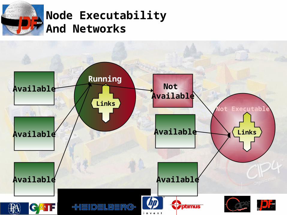
Not Available
Available
Available
Not Executable
Running
Links
Available
Available
Available
Links
Node ExecutabilityAnd Networks

Available
Available
Available
Executable
Links
Completed
Links
Available
Available
Available
Node ExecutabilityAnd Networks

CoverCover
EndSheets
EndSheets
ReaderPages
ReaderPages
BookBook
ContentsContents
Job Description Models supported by JDF I
• Product Definition
– No Process
– Abstract, customer view
– Segmentation by Product
Components
• Serial Processing
RIPRIP PrintPrint BindBind

Job Description Models supported by JDF II
• Parallel Processing
• Overlapping Processing
RIPRIP
PrintPrint
PrintPrint
BindBind
BindBindRIPRIP PrintPrint

Job Description Models supported by JDF III
• Iterative Processing
– Informal Iterative Processing using Draft Resources
– Formal Iterative Processing using JMF Messages
EditEdit TouchupTouchup
LayoutLayout

JDF Tree / Network Structure
parent JD Fnode
1 2 3 A 7
4 5 6 P rocess A : 4 + 5 + 6
1
2
3
4 5
6
7in. out.
JDF - Spawning and Merging
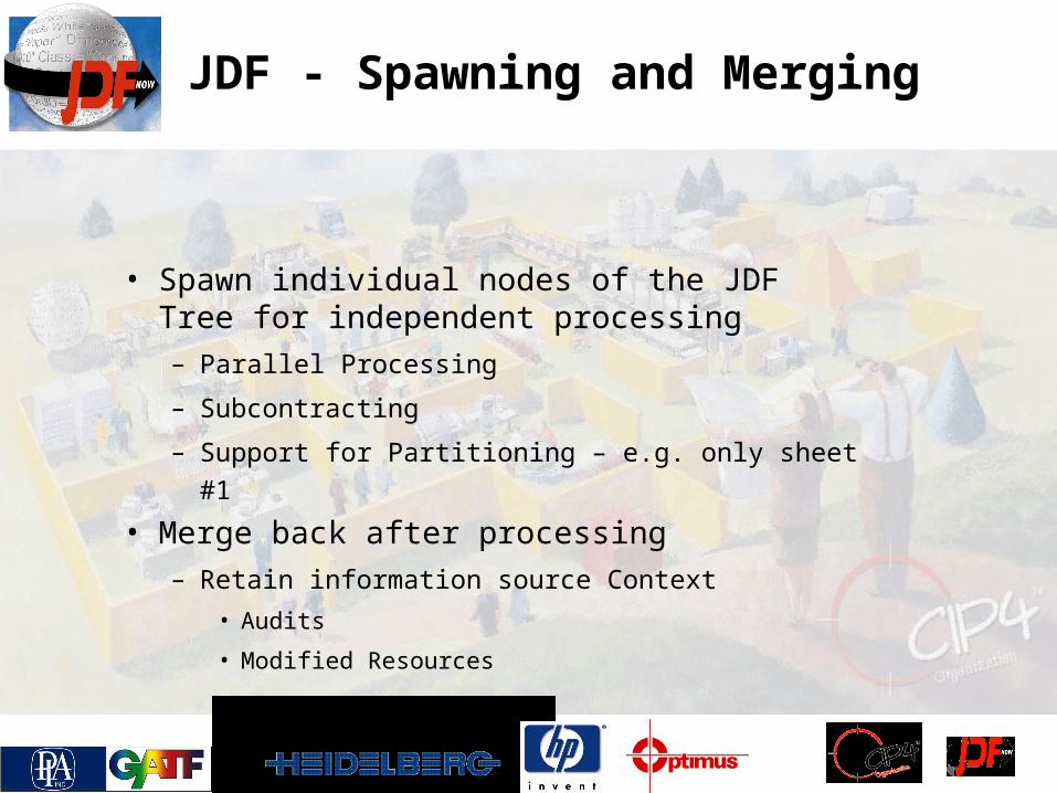
• Spawn individual nodes of the JDF Tree for independent processing– Parallel Processing
– Subcontracting
– Support for Partitioning – e.g. only sheet #1
• Merge back after processing– Retain information source Context
• Audits
• Modified Resources
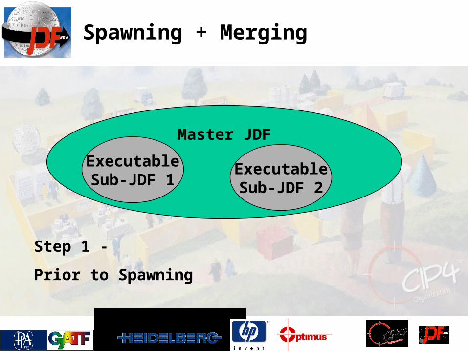
Spawning + Merging
Master JDF
ExecutableSub-JDF 1
ExecutableSub-JDF 2
Step 1 -
Prior to Spawning

Spawning + Merging
Master JDF
ExecutableSub-JDF 1
LockedSub-JDF 2
Spawned Executable
Sub-JDF
Step 2 -
Spawned,
Prior to Execution
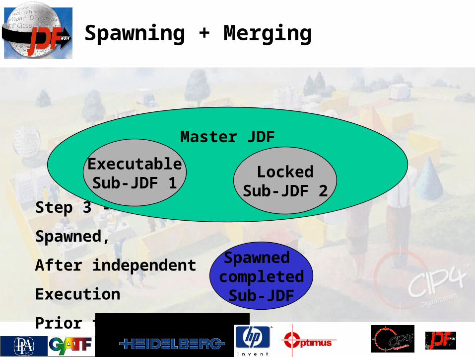
Spawning + Merging
Master JDF
ExecutableSub-JDF 1
LockedSub-JDF 2
Spawned completedSub-JDF
Step 3 -
Spawned,
After independent
Execution
Prior to merging

Spawning + Merging
Master JDF
ExecutableSub-JDF 1
MergedSub-JDF 2
Step 4 -
After Execution
After Merging

JMF Messaging
• Real-time data interchange format• Small XML structures
– JDF is referenced via URL, not bound into message
– Idea is to minimize network traffic and delay transmission of data until it is actually needed

JMF Messaging
• Used for:– Plug + Play bootstrapping
– Snapshots of Job / Device status
– Dynamic job update
– Job submission and Queue/QueueEntry handling
– Capabilities discovery and interchange

JMF Message Families
• JMF messages fall into five categories– Command
• Receiver is instructed to take an action, or to modify the state of something
– Query• Receiver is instructed to return information about
something. No action is taken, no states are changed
– Response• Used to immediately return result of command or
query• Synchronous messaging – command/query and
response are exchanged on same open connection

JMF Message Families
• JMF message categories (cont’d)– Acknowledgement
• Used to return the result of a command after some time has passed
• Asynchronous messaging – empty response returned immediately on same connection as command with indication that Acknowledgement will be sent later
– Signal• Used to send notifications of events or change in
status• Typically result of a query with a subscription
embedded in it• Subscription sets up persistent channel

Example – SubmitQueueEntry message:
<JMF DeviceID="SP013" SenderID="MIS1“TimeStamp="2004-11-15T12:32:48-
06:00">
<Command ID="m3829" Type="SubmitQueueEntry">
<QueueSubmissionParamsURL="http://jobserver/getJob?
job=10047"
ReturnJMF="http://jobserver/jmfservice"
Priority="50"/>
</Command>
</JMF>

JMF Message Types
• Examples of JMF message that fall within the five categories– Command
• SubmitQueueEntry, AbortQueueEntry, ReturnQueueEntry, HoldQueue, ResumeQueue
– Query• KnownControllers, KnownDevices, Status
– Response• Various related to various commands/queries
– Acknowledgement• Various related to various commands/queries
– Signal• Status, Resource, Occupation

CIP4 Open Source Development Tools
• XML Schema
• C++ API
• Java API
• JDF Editor
– Visualise JDF + JMF
– Send Messages
• Elk Project
– Reference Device

History of JDF
1999: Adobe, Agfa, MAN and Heidelberg form the GAT initiative with the goal of defining a job ticket for the Graphic Arts that also integrates MIS.
2000: The CIP3 Consortium takes ownership of the standard.2001: JDF 1.0 is released.2002: JDF 1.1 is released.
– Ambiguities/Bugs found in implementation were removed
– Additional Processes were added
– Consistency between diverse areas was enhanced
2004: JDF 1.2 is released
– More additional processes
– Even more mature and consistent
2005: First set of ICS documents are published

Experience with JDF - Advantages
Single grammar for specifying job data in the graphic arts industry
Integration of Production, Customer and MIS Multiple views for Production, Customer and MIS Definition of production networks Combined Processes Defined communication protocol, not only data
structures Extensible Model Interaction with other Standards in GA

Experience with JDF - Challenges / Obstacles
Number of processes in the graphic arts
Creative
Prepress
Press
Finishing
Fulfillment Complexity of the standard
Size of the Specification
Moving from the Abstract Idea to a Concrete Implementation
Flexibility of the Specification
Unclear Role of Production networks in Interfacing with Devices
private extensions
Definition of abstract coordinate systems Legacy System Longevity

Why ICS ?
JDF A
ICS
JDF B
Product A Product B
InteroperabilityConformanceSpecifications

Interoperability Conformance Specifications
• Define a set of Interoperability Conformance Specifications – ICS
– The term “JDF Compliant” does not immediately imply
that two arbitrary applications will communicate.
• Sending RIP instructions to a Folding Machine is not useful…
– Two applications that comply with a given ICS will
communicate in a meaningful way.
– Product Certification will be based on ICS Compliance
• Avoid multiple, incompatible JDF Dialects

ICS Document Structure
Base ICS
JDF Specification
Prepress to Conv. Printing
ICSMIS Base ICS
MIS Sheet
ConvPrint ICS
MIS Prepress
ICS
MIS Binding
ICS
TBDMIS
DOMAIN ICS
MIS Integ.
DigiPrint ICS

JDF Tutorial
Thank you very much for your attention!