
Welcome to the CIM University - Home - UCAIug CIM Standards Overview and CIM’s Role in the Utility...
60
1 Welcome to the CIM University New Oreleans, Louisiana, USA 22 October 2012
Transcript of Welcome to the CIM University - Home - UCAIug CIM Standards Overview and CIM’s Role in the Utility...
1
Welcome to the CIM University
New Oreleans, Louisiana, USA22 October 2012
2
CIM Standards Overview and CIM’s Role in the Utility
Enterprise – Part 1
CIM Users GroupNew Orleans, Louisiana, USA22 October 2012Terry Saxton
3
Presentation Contents
• Background• What is the CIM• How the CIM is used in the Utility Enterprise• Three Layer Architecture for Using the CIM Standards• CIM UML model• Profiles for business context• Implementation syntax• IEC CIM Working Groups and Standards• CIM as Basis for Enterprise Semantic Model (ESM)• Case studies• Where to get CIM information
4
The IEC Common Information Model (CIM) - What Is It?
• A set of standards in enable system integration and information exchange based on a common information model
– Provides a general information model and message/file schemas for messages/files exchanged between systems
• A key differentiator: The CIM standards are based on a Unified Modeling Language (UML) based information model representing real-world objects and information entities exchanged within the value chain of the electric power industry
– Provides common semantics for all information exchangesReferred to as Model-Driven Integration (MDI)
– Not tied to a particular application’s view of the world• But permits same model to be used by all applications to facilitate information sharing
between applications– Maintained by IEC in Sparx Enterprise Architect modeling tools– Many tools available generating design artifacts and documentation– Enable data access to enterprise data warehouse in a standard way
5
6
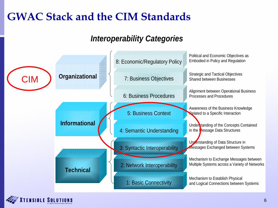
GWAC Stack and the CIM Standards
Organizational
Technical
Informational
8: Economic/Regulatory Policy
7: Business Objectives
6: Business Procedures
3: Syntactic Interoperability
5: Business Context
2: Network Interoperability
4: Semantic Understanding
1: Basic Connectivity
Interoperability Categories
Political and Economic Objectives as Embodied in Policy and Regulation
Strategic and Tactical Objectives Shared between Businesses
Alignment between Operational Business Processes and Procedures
Awareness of the Business Knowledge Related to a Specific Interaction
Understanding of the Concepts Contained in the Message Data Structures
Understanding of Data Structure in Messages Exchanged between Systems
Mechanism to Exchange Messages between Multiple Systems across a Variety of Networks
Mechanism to Establish Physical and Logical Connections between Systems
CIM
7
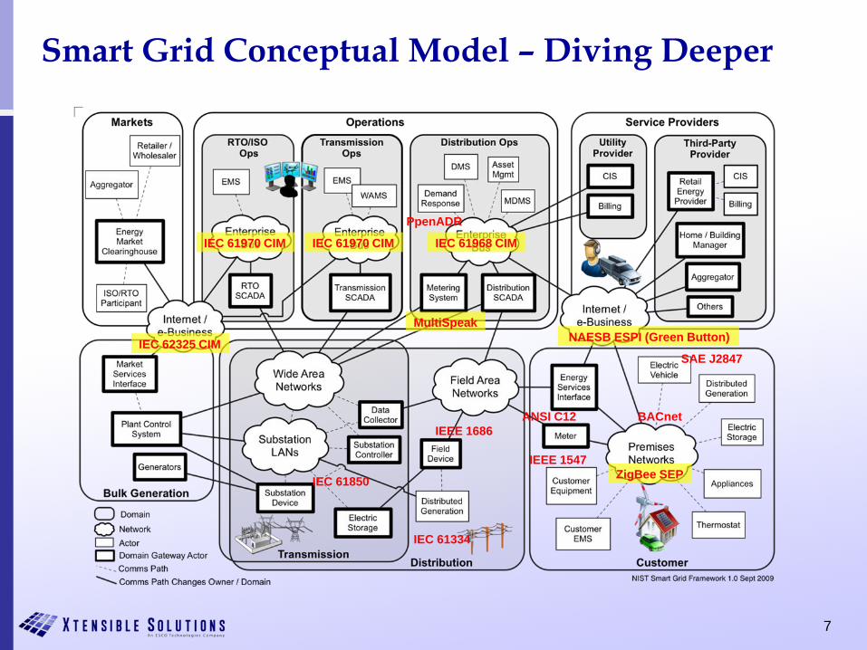
Smart Grid Conceptual Model – Diving Deeper
IEC 62325 CIM
IEC 61850
IEC 61334
IEEE 1686
IEEE 1547
ANSI C12
ZigBee SEP
BACnet
SAE J2847
NAESB ESPI (Green Button)MultiSpeak
IEC 61968 CIM
PpenADR
IEC 61970 CIMIEC 61970 CIM
8
Role of CIM in Smart Grid Architecture
• CIM standards aim to simplify integration of components and expand options for supply of components by standardizing information exchanges– Reduce complexity with clear consistent semantic modeling
across the enterprise– Data sources: achieve a clear picture of data mastership in the
enterprise – Data consumers: make ‘data of record’ available on demand to
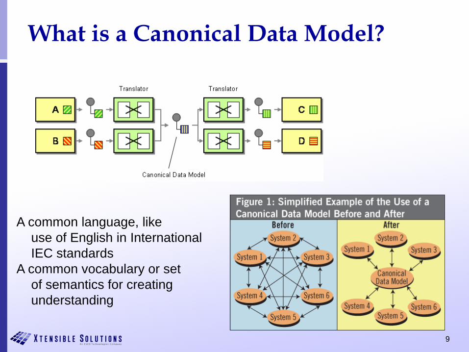
qualified users• CIM employs a canonical data model (CDM) strategy for
standardizing interfaces in the power system operations and planning domain.
9
What is a Canonical Data Model?
A common language, likeuse of English in InternationalIEC standards
A common vocabulary or set of semantics for creatingunderstanding

10
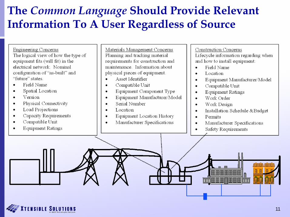
The Common Language Should Provide Relevant Information To A User Regardless of Source
EngineeringConcerns
MaterialsManagement
ConcernsConstruction
Concerns
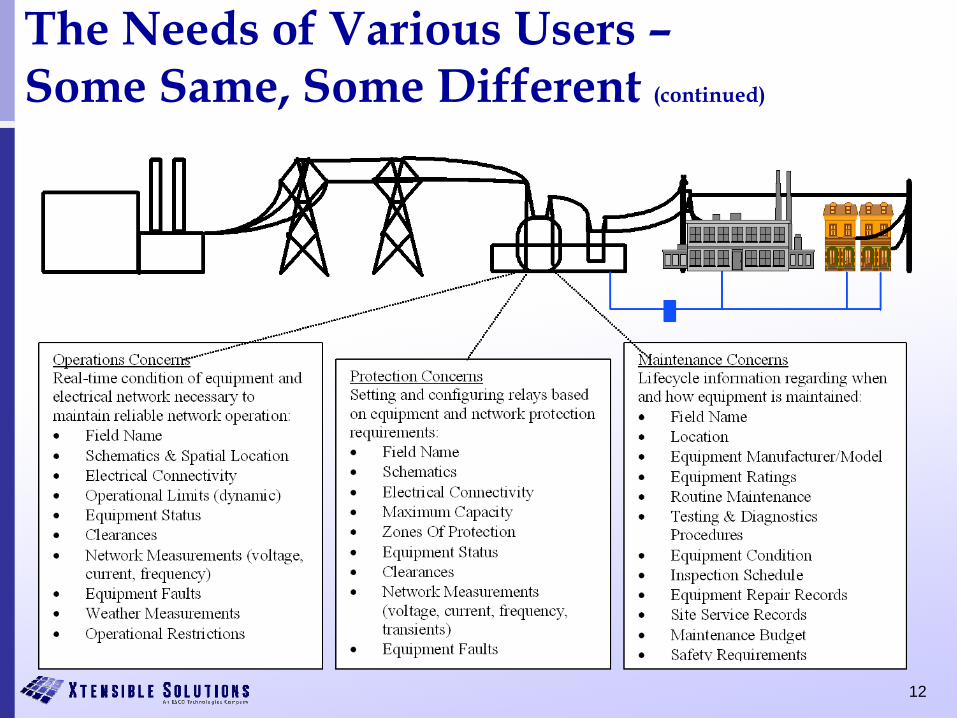
OperationsConcerns
ProtectionConcerns
MaintenanceConcerns
11
The Common Language Should Provide Relevant Information To A User Regardless of Source
12
The Needs of Various Users –Some Same, Some Different (continued)
13
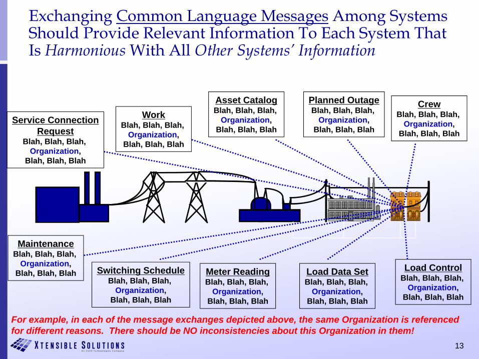
Exchanging Common Language Messages Among Systems Should Provide Relevant Information To Each System That Is Harmonious With All Other Systems’ Information
WorkBlah, Blah, Blah,
Organization,Blah, Blah, Blah
MaintenanceBlah, Blah, Blah,
Organization,Blah, Blah, Blah Switching Schedule
Blah, Blah, Blah, Organization,
Blah, Blah, Blah
Load Data SetBlah, Blah, Blah,
Organization,Blah, Blah, Blah
Meter ReadingBlah, Blah, Blah,
Organization,Blah, Blah, Blah
Load ControlBlah, Blah, Blah,
Organization,Blah, Blah, Blah
Asset CatalogBlah, Blah, Blah,
Organization,Blah, Blah, Blah
CrewBlah, Blah, Blah,
Organization,Blah, Blah, Blah
Service ConnectionRequest
Blah, Blah, Blah, Organization,
Blah, Blah, Blah
Planned OutageBlah, Blah, Blah,
Organization,Blah, Blah, Blah
For example, in each of the message exchanges depicted above, the same Organization is referenced for different reasons. There should be NO inconsistencies about this Organization in them!
14
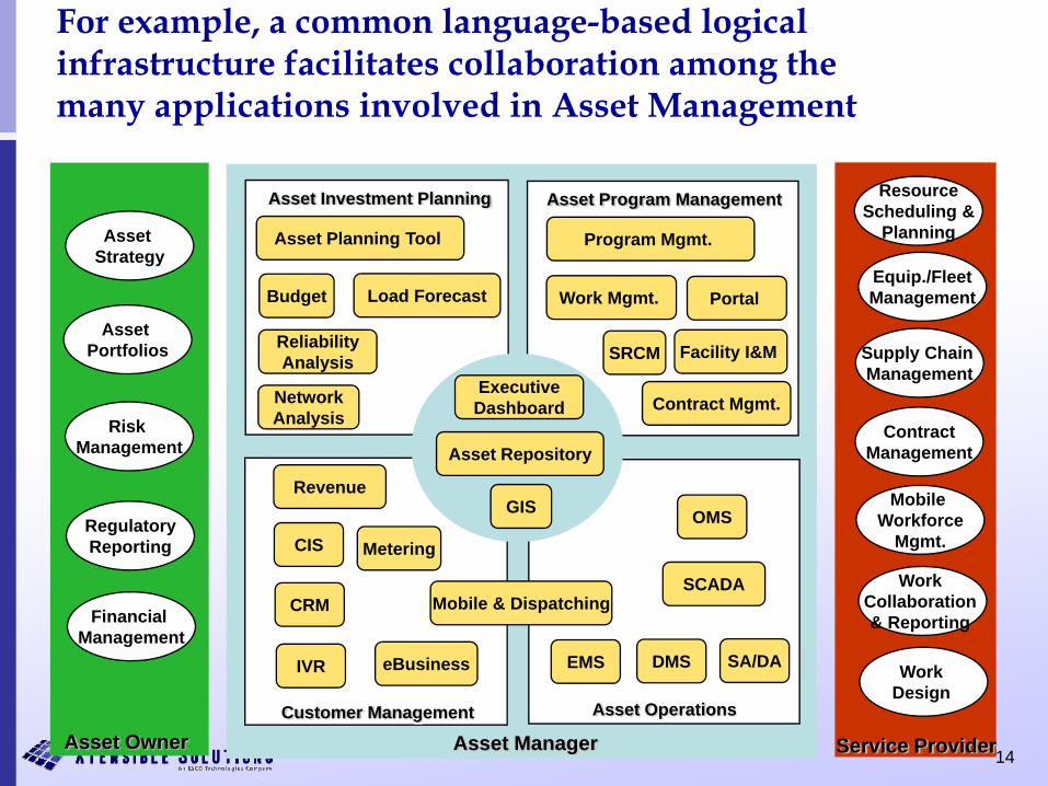
For example, a common language-based logical infrastructure facilitates collaboration among the many applications involved in Asset Management
Asset Strategy
Asset Portfolios
Risk Management
RegulatoryReporting
Financial Management
ResourceScheduling &
Planning
Equip./FleetManagement
Supply Chain Management
ContractManagement
Mobile Workforce
Mgmt.
Work Collaboration & Reporting
Work Design
Asset Owner Asset Manager Service Provider
Asset Investment Planning Asset Program Management
Customer Management Asset Operations
CIS
CRM
IVR eBusiness EMS DMS
SCADA
OMS
Asset Planning Tool
Budget Load Forecast
ReliabilityAnalysis
NetworkAnalysis
Asset Repository
ExecutiveDashboard
Program Mgmt.
Work Mgmt.
Mobile & Dispatching
Contract Mgmt.
GISRevenue
Facility I&M
Portal
SA/DA
Metering
SRCM

15
Application To Common Language Mapping –The Typical Field to Field Process Is Cumbersome
• Individual fields of data models from data sources are mapped to each other
• Approach does not scale well as the number of maps grows exponentially with each new data source
• Mapping is a challenge as ‘mappers’ must have an in depth understanding of all relevant data sources – a tall order!
16
Using A Semantic Model ToSimplify & Scale Up The Mapping Process
• What is a Semantic Model?– The key ingredients that make up a semantic model are a vocabulary of
basic terms, a precise specification of what those terms mean and how they relate to each other.
• How is it used?– Before making mappings, a model (or an ontology) of a given business
domain is defined. – The model is expressed in a knowledge representation language and it
contains business concepts, relationships between them and a set of rules. – By organizing knowledge in a discrete layer for use by information
systems, semantic models enable communication between computer systems in a way that is independent of the individual system technologies, information architectures and applications.
– Compared to one-to-one mappings, mapping data sources to a common semantic model offer a much more scaleable and maintainable way to manage and integrate enterprise data.
17
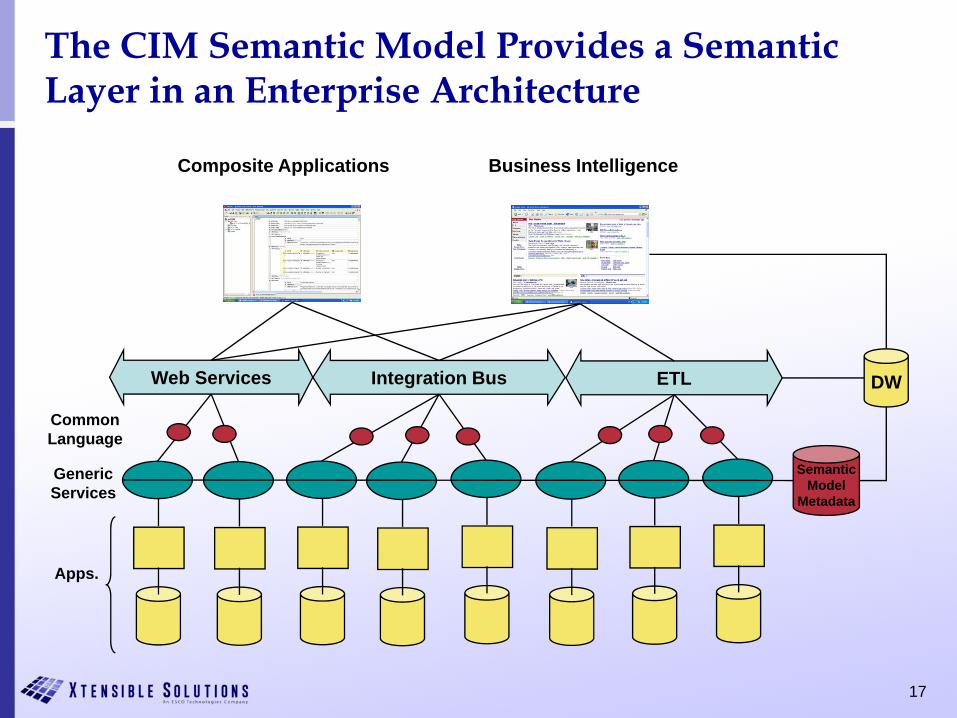
ETLIntegration BusWeb Services
Apps.
GenericServices
Composite Applications
DW
Business Intelligence
CommonLanguage
SemanticModel
Metadata
The CIM Semantic Model Provides a Semantic Layer in an Enterprise Architecture
18
App CIMY.1 X.1Y.2 X.2Y.3 X.3Y.4 X.4Y.5 X.5
Publisher
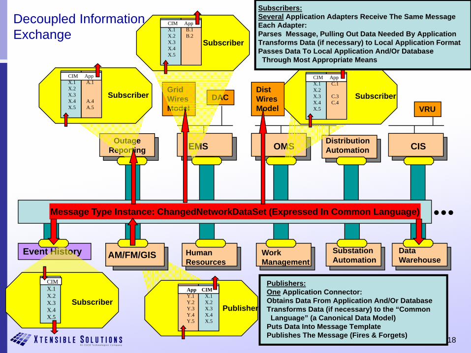
Publishers:One Application Connector:Obtains Data From Application And/Or DatabaseTransforms Data (if necessary) to the “CommonLanguage” (a Canonical Data Model)
Puts Data Into Message TemplatePublishes The Message (Fires & Forgets)
DataWarehouse
SubstationAutomation
OMS
DistWiresModel
GridWiresModel
DAC
CIS
VRU
AM/FM/GIS
DistributionAutomation
HumanResources
OutageReporting
Event History WorkManagement
EMS
...
CIMX.1 X.2 X.3 X.4 X.5
Subscriber
CIM AppX.1 B.1X.2 B.2X.3 X.4 X.5
Subscriber
CIM AppX.1 A.1X.2 X.3 X.4 A.4X.5 A.5
Subscriber
CIM AppX.1 C.1X.2 X.3 C.3X.4 C.4X.5
Subscriber
Subscribers:Several Application Adapters Receive The Same MessageEach Adapter:Parses Message, Pulling Out Data Needed By ApplicationTransforms Data (if necessary) to Local Application FormatPasses Data To Local Application And/Or Database Through Most Appropriate Means
Message Type Instance: ChangedNetworkDataSet (Expressed In Common Language)
Decoupled InformationExchange
19
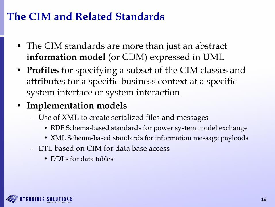
The CIM and Related Standards
• The CIM standards are more than just an abstract information model (or CDM) expressed in UML
• Profiles for specifying a subset of the CIM classes and attributes for a specific business context at a specific system interface or system interaction
• Implementation models– Use of XML to create serialized files and messages
• RDF Schema-based standards for power system model exchange• XML Schema-based standards for information message payloads
– ETL based on CIM for data base access• DDLs for data tables
20
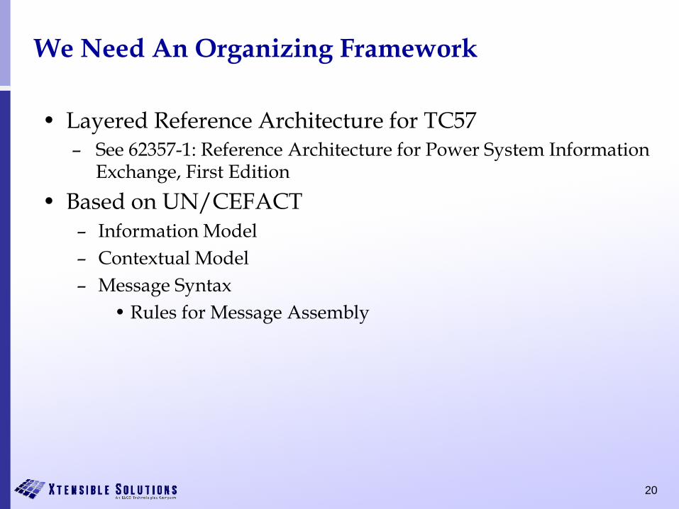
We Need An Organizing Framework
• Layered Reference Architecture for TC57– See 62357-1: Reference Architecture for Power System Information
Exchange, First Edition• Based on UN/CEFACT
– Information Model– Contextual Model– Message Syntax
• Rules for Message Assembly
21
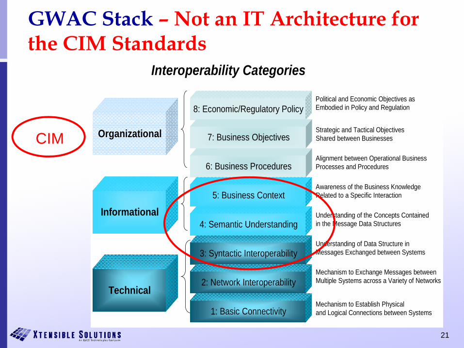
GWAC Stack – Not an IT Architecture for the CIM Standards
Organizational
Technical
Informational
8: Economic/Regulatory Policy
7: Business Objectives
6: Business Procedures
3: Syntactic Interoperability
5: Business Context
2: Network Interoperability
4: Semantic Understanding
1: Basic Connectivity
Interoperability Categories
Political and Economic Objectives as Embodied in Policy and Regulation
Strategic and Tactical Objectives Shared between Businesses
Alignment between Operational Business Processes and Procedures
Awareness of the Business Knowledge Related to a Specific Interaction
Understanding of the Concepts Contained in the Message Data Structures
Understanding of Data Structure in Messages Exchanged between Systems
Mechanism to Exchange Messages between Multiple Systems across a Variety of Networks
Mechanism to Establish Physical and Logical Connections between Systems
CIM
22
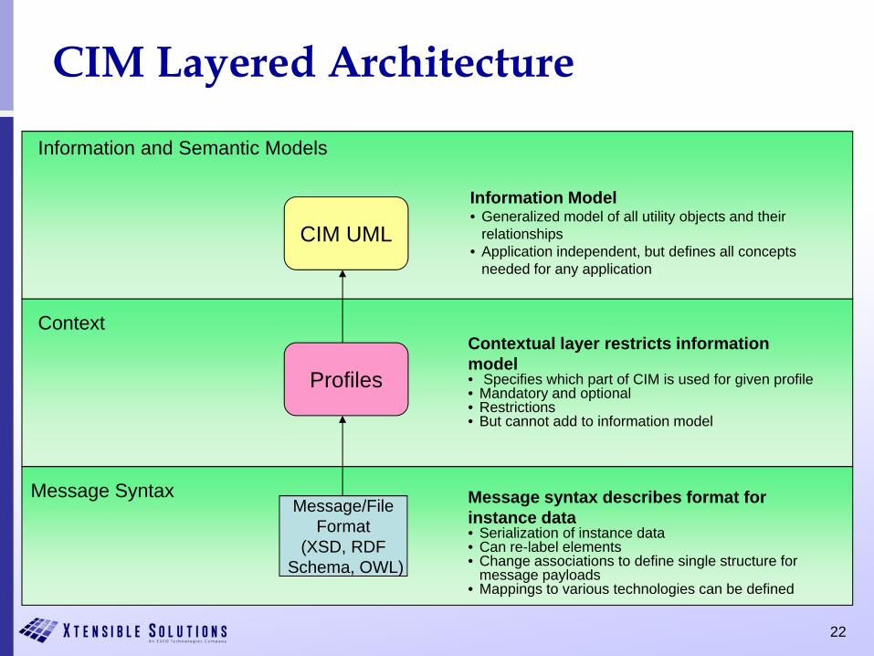
CIM Layered Architecture
CIM UML
Information and Semantic Models
Context
Message Syntax
Profiles
Message/FileFormat
(XSD, RDFSchema, OWL)
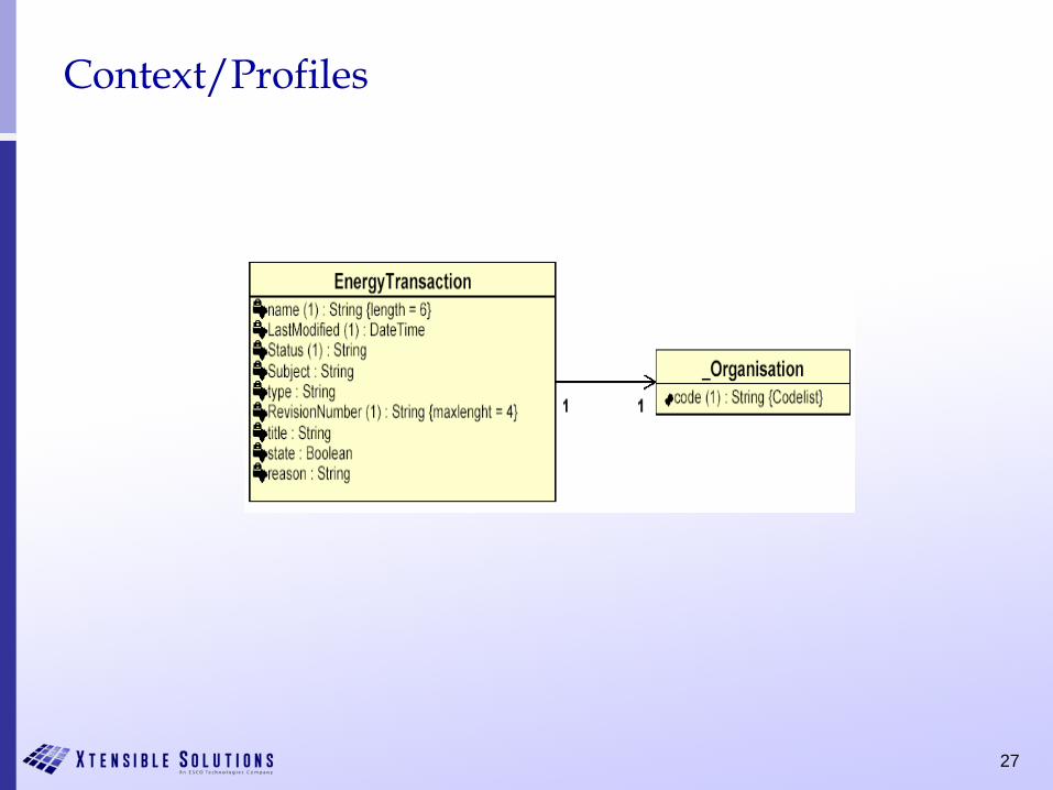
Contextual layer restricts information model• Specifies which part of CIM is used for given profile• Mandatory and optional• Restrictions• But cannot add to information model
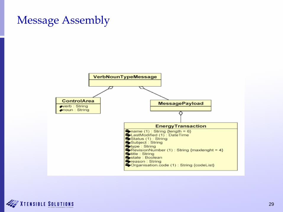
Message syntax describes format for instance data• Serialization of instance data• Can re-label elements• Change associations to define single structure for
message payloads• Mappings to various technologies can be defined
Information Model• Generalized model of all utility objects and their
relationships• Application independent, but defines all concepts
needed for any application
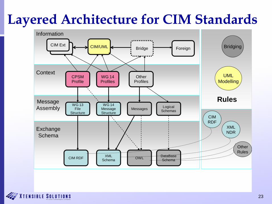
23
CIM RDF
CIM/UML
CPSMProfile
CIMCIM Ext
Bridge Foreign
WG 14Profiles
OtherProfiles
Messages
XMLSchema OWL DataBase
Schema
CIMRDF
XMLNDR
OtherRules
Information
Context
MessageAssembly
ExchangeSchema
Rules
UMLModelling
Logical Schemas
Bridging
WG 14Message Structure
WG 13File
Structure
Layered Architecture for CIM Standards
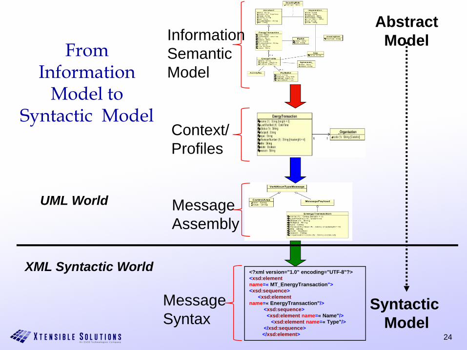
24
From Information
Model to Syntactic Model
AbstractModel
Syntactic Model
<?xml version="1.0" encoding="UTF-8"?><xsd:elementname=« MT_EnergyTransaction"><xsd:sequence>
<xsd:elementname=« EnergyTransaction"/>
<xsd:sequence><xsd:element name=« Name"/>
<xsd:element name=« Type"/></xsd:sequence>
</xsd:element>
UML World
XML Syntactic World
Information/SemanticModel
Context/Profiles
MessageAssembly
MessageSyntax
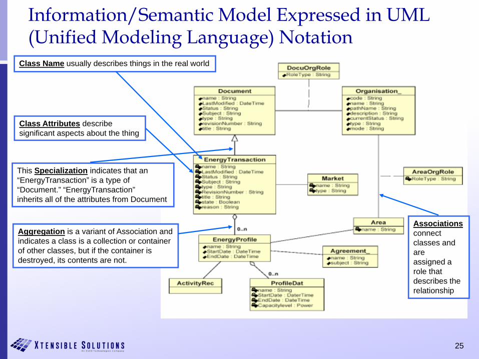
25
Information/Semantic Model Expressed in UML (Unified Modeling Language) Notation
Class Name usually describes things in the real world
Class Attributes describesignificant aspects about the thing
This Specialization indicates that an “EnergyTransaction” is a type of“Document.” “EnergyTransaction” inherits all of the attributes from Document
Aggregation is a variant of Association and indicates a class is a collection or container of other classes, but if the container is destroyed, its contents are not.
Associationsconnect classes and areassigned a role that describes the relationship
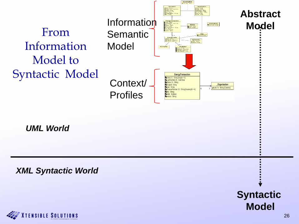
26
From Information
Model to Syntactic Model
AbstractModel
Syntactic Model
UML World
XML Syntactic World
Information/SemanticModel
Context/Profiles
27
Context/Profiles
28
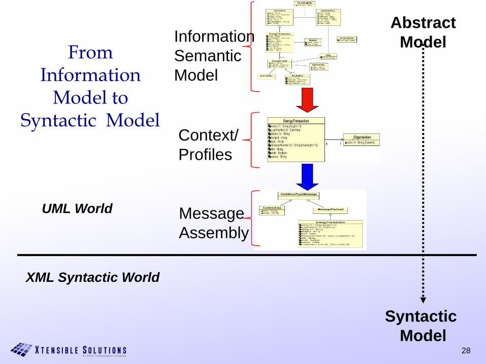
From Information
Model to Syntactic Model
AbstractModel
Syntactic Model
UML World
XML Syntactic World
Information/SemanticModel
Context/Profiles
MessageAssembly
29
Message Assembly

30
From Information
Model to Syntactic Model
AbstractModel
Syntactic Model
<?xml version="1.0" encoding="UTF-8"?><xsd:elementname=« MT_EnergyTransaction"><xsd:sequence>
<xsd:elementname=« EnergyTransaction"/>
<xsd:sequence><xsd:element name=« Name"/>
<xsd:element name=« Type"/></xsd:sequence>
</xsd:element>
UML World
XML Syntactic World
Information/SemanticModel
Context/Profiles
MessageAssembly
MessageSyntax
31
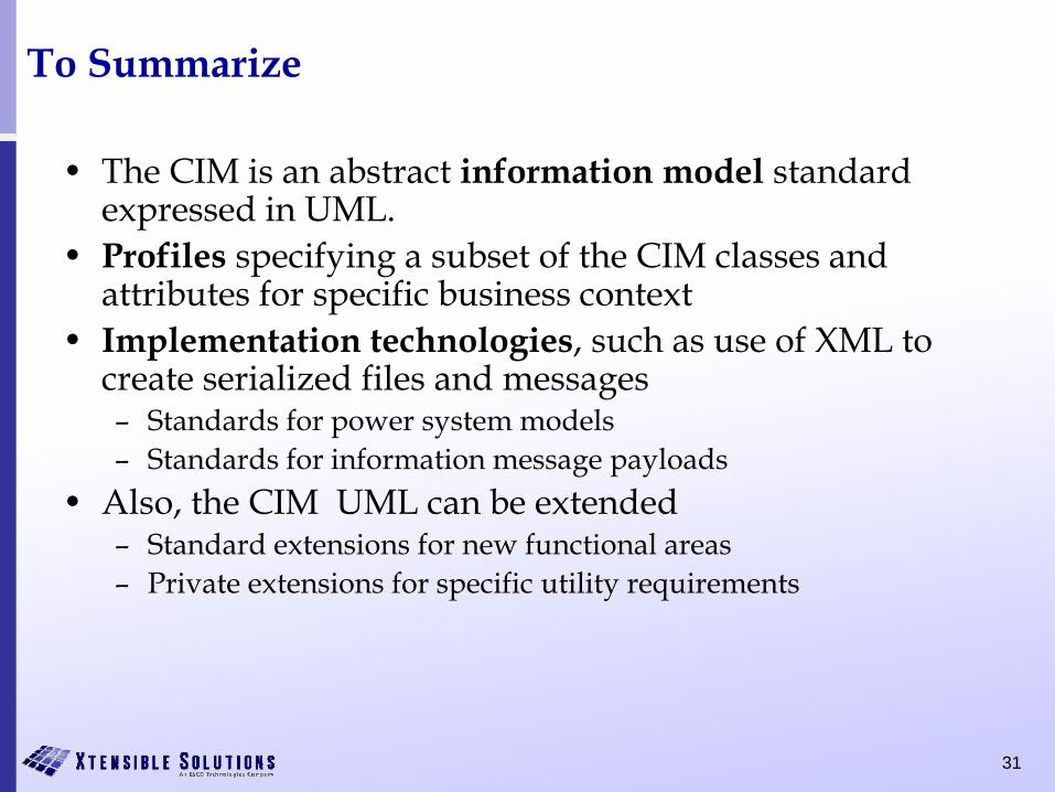
To Summarize
• The CIM is an abstract information model standard expressed in UML.
• Profiles specifying a subset of the CIM classes and attributes for specific business context
• Implementation technologies, such as use of XML to create serialized files and messages– Standards for power system models– Standards for information message payloads
• Also, the CIM UML can be extended– Standard extensions for new functional areas– Private extensions for specific utility requirements
32
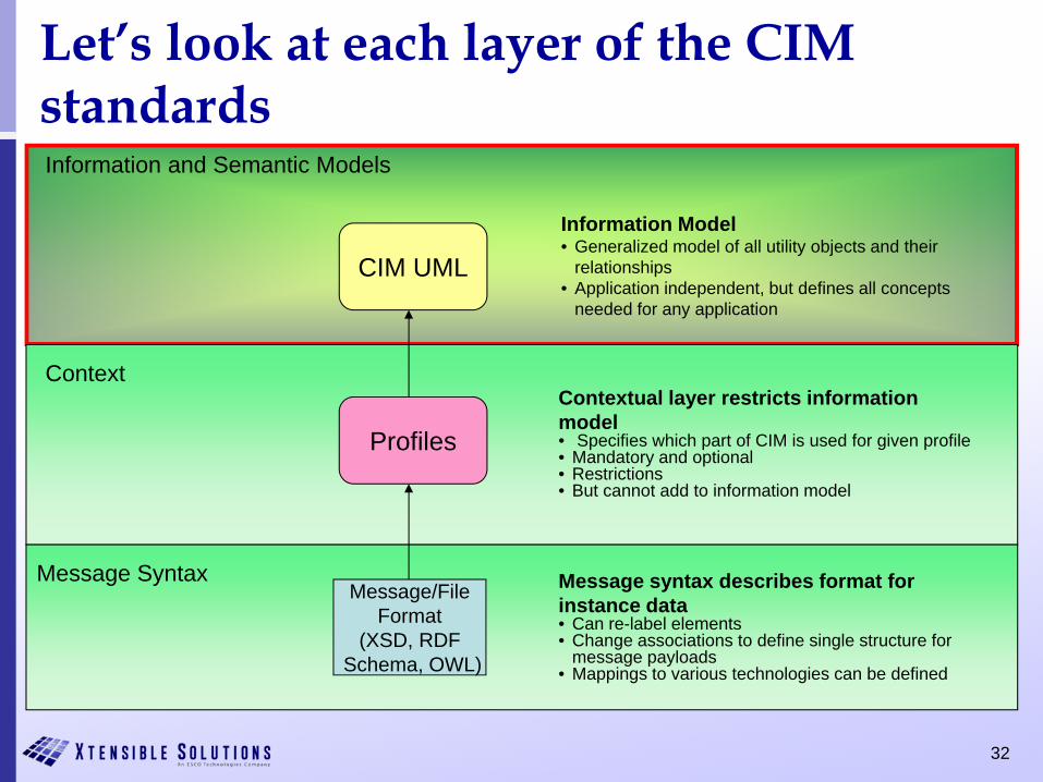
Let’s look at each layer of the CIM standards
CIM UML
Information and Semantic Models
Context
Message Syntax
Profiles
Message/FileFormat
(XSD, RDFSchema, OWL)
Contextual layer restricts information model• Specifies which part of CIM is used for given profile• Mandatory and optional• Restrictions• But cannot add to information model
Message syntax describes format for instance data• Can re-label elements• Change associations to define single structure for
message payloads• Mappings to various technologies can be defined
Information Model• Generalized model of all utility objects and their
relationships• Application independent, but defines all concepts
needed for any application
33
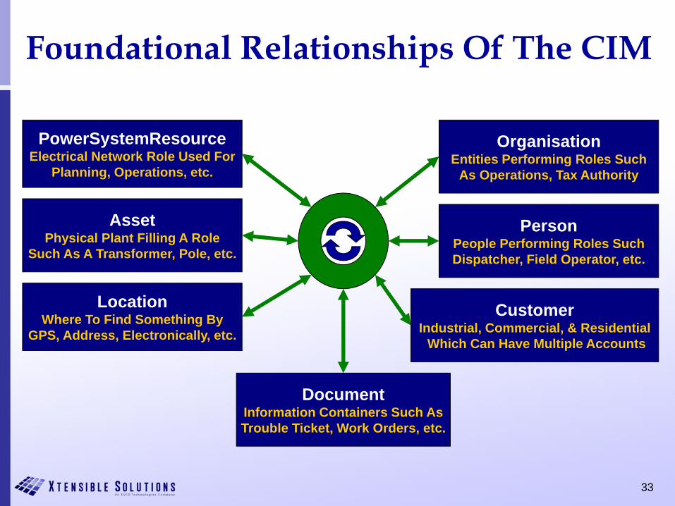
Foundational Relationships Of The CIM
PowerSystemResourceElectrical Network Role Used For
Planning, Operations, etc.
AssetPhysical Plant Filling A Role
Such As A Transformer, Pole, etc.
LocationWhere To Find Something By
GPS, Address, Electronically, etc.
OrganisationEntities Performing Roles Such
As Operations, Tax Authority
PersonPeople Performing Roles SuchDispatcher, Field Operator, etc.
DocumentInformation Containers Such AsTrouble Ticket, Work Orders, etc.
CustomerIndustrial, Commercial, & Residential
Which Can Have Multiple Accounts
34
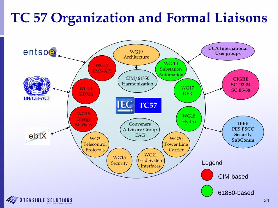
UCA InternationalUser groups
TC 57 Organization and Formal Liaisons
IEEEPES PSCCSecurity
SubComm
WG14SIDMS
WG19Architecture
WG13EMS-API
WG 10Substation
AutomationCIGRE
SC D2-24SC B5-38
TC57
CIM/61850Harmonization
WG17DER
WG16EnergyMarkets
WG18Hydro
WG15Security Legend
CIM-based
61850-based
WG3TelecontrolProtocols
WG20Power Line
Carrier
ConvenersAdvisory Group
CAG
WG21Grid System
Interfaces
35
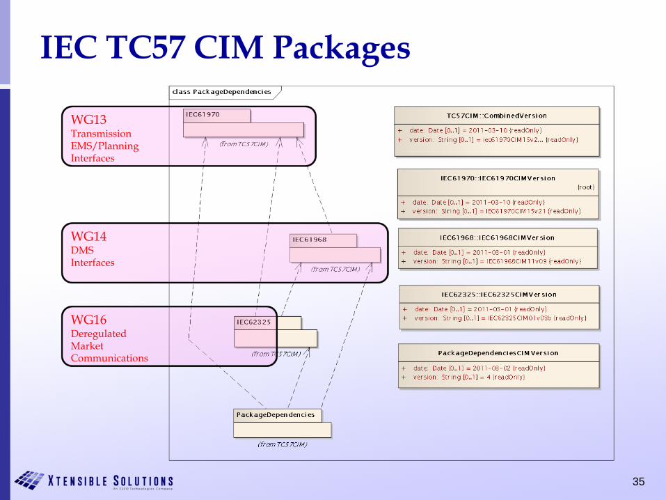
IEC TC57 CIM Packages
WG13TransmissionEMS/Planning Interfaces
WG14DMSInterfaces
WG16DeregulatedMarketCommunications
36
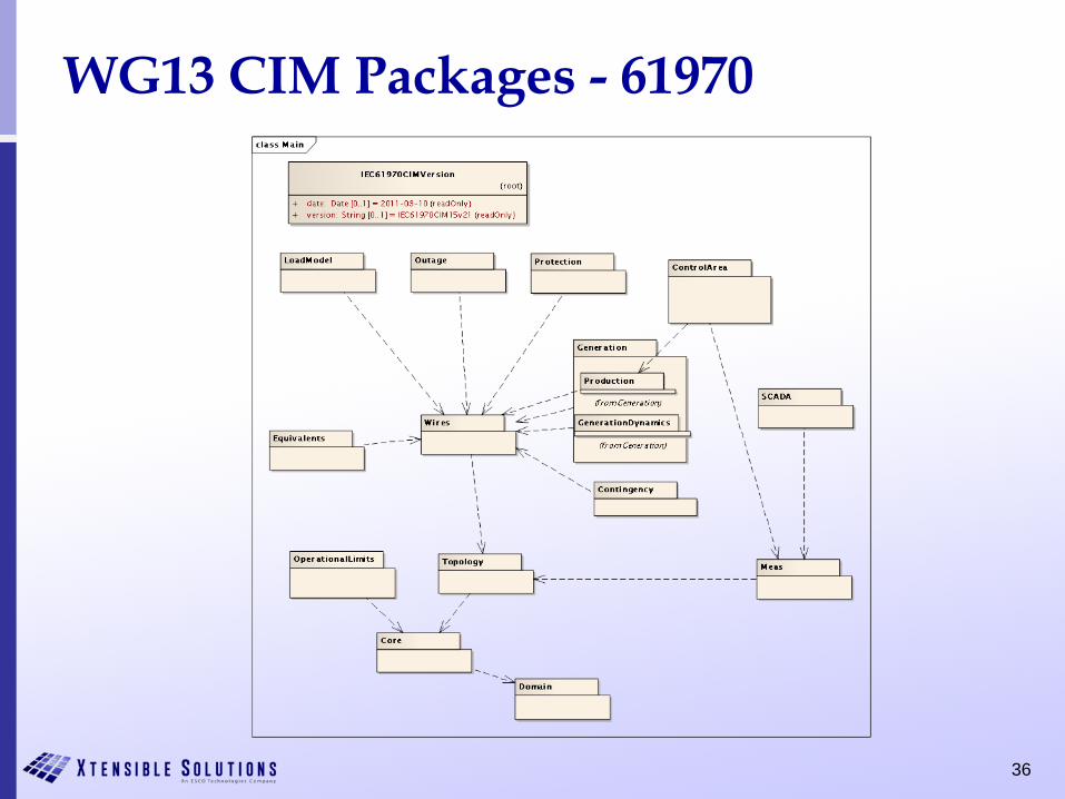
WG13 CIM Packages - 61970
37
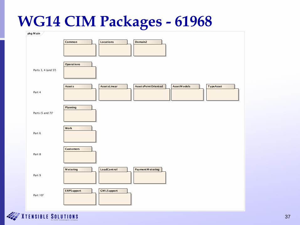
WG14 CIM Packages - 61968pkg M ain
AssetsPointOriented
Customers
Common
Operations
ERPSupport
Work
Assets
M etering PaymentM etering
Domain2Locations
TypeAssetAssetM odelsAssetsLinear
Planning
LoadControl
GM LSupport
Parts 3, 4 (and 5?)
Part 4
Parts (5 and 7)?
Part 6
Part 8
Part 9
Part 10?
38
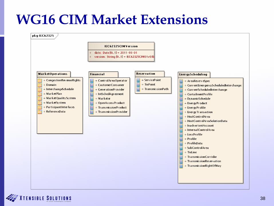
WG16 CIM Market Extensions
39
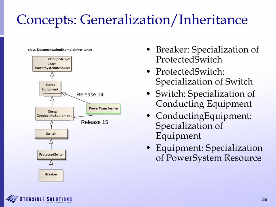
Concepts: Generalization/Inheritance
• Breaker: Specialization of ProtectedSwitch
• ProtectedSwitch: Specialization of Switch
• Switch: Specialization of Conducting Equipment
• ConductingEquipment: Specialization of Equipment
• Equipment: Specialization of PowerSystem Resource
class DocumentationExampleInheritance
IdentifiedObject
Core::PowerSystemResource
Core::
Equipment
Core::ConductingEquipment
Breaker
ProtectedSwitch
PowerTransformer
Switch
Release 14
Release 15
4040
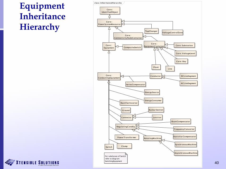
Equipment InheritanceHierarchy
cla ss Inher i tanceHier a r chy
Cor e::Power Sy stemResour ce
Busba r Sect ion
VoltageContr olZone
ShuntCompensator
ACLineSegment
DCLineSegment
Cor e::VoltageLev el
TapChanger
Sta t icVar Compensa tor
Regula t ingCondEq
Rect if ier Inv er ter
Junct ion
Gr ound
Conductor
Ener gy Sour ce
Ser iesCompensa tor
Cor e::Ident i f iedObject
P lantLine
Fr equency Conv er ter
Connector
Cor e::Bay
Switch
Cor e::Connect iv i ty NodeConta iner
Cor e::Substa t ion
Ener gy Consumer
Cor e::Conduct ingEquipment
Sy nchr onousMachine
Cor e::Equipment
Cor e::EquipmentConta inerCompositeSwitch
For subclasses of Switch refer to diagram SwitchingEquipment
Rota t ingMachine
Asy nchr onousMachine
Power Tr ansfor mer
Clamp
4141
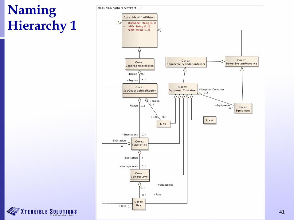
NamingHierarchy 1
class NamingHier a r chy Pa r t1
Cor e::Substa t ion
Cor e::Bay
Cor e::VoltageLev el
Cor e::SubGeogr aphica lRegion
Line
Cor e::Geogr aphica lRegion
Cor e::Ident if iedObject
+ aliasName: String [0..1]+ mRID: String [0..1]+ name: String [0..1]
Cor e::Equipment
Cor e::EquipmentConta iner
Cor e::Power Sy stemResour ce
P lant
Cor e::Connect iv ity NodeConta iner
+EquipmentContainer0..1
+Equipments0..*
+Region 0..1
+Regions 0..*
+Region 0..1
+Substations 0..*
+Region0..1
+Lines 0..*
+VoltageLevel0..1
+Bays0..*
+Bays 0..*
+Substation
0..1
+Substation 1
+VoltageLevels 0..*
4242
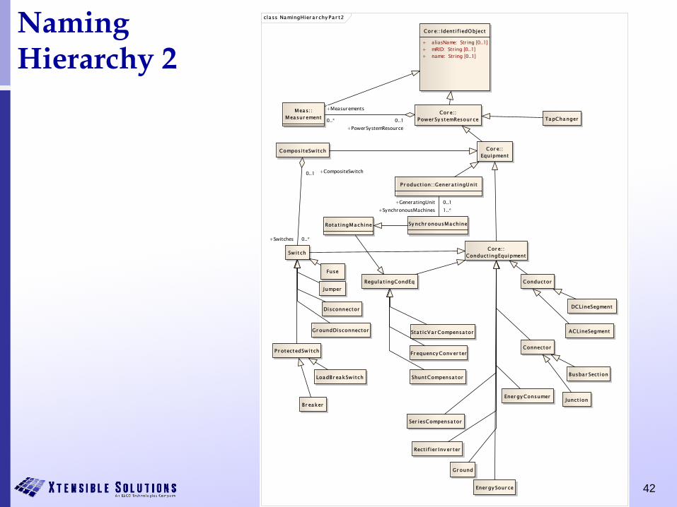
NamingHierarchy 2
cla ss NamingHier a r chy Pa r t2
Fuse
Ener gy Consumer
ShuntCompensa tor
Connector
Busbar Sect ion
Br eaker
ACLineSegment
Disconnector
Jumper
Fr equency Conv er ter
Ener gy Sour ce
Sta t icVar Compensa tor
Rect i f ier Inv er ter
Conductor
Cor e::Conduct ingEquipment
Cor e::Equipment
DCLineSegment
Sy nchr onousMachine
CompositeSwitch
Switch
Meas::Measur ement
Cor e::Power Sy stemResour ce TapChanger
Gr ound
Regula t ingCondEq
Gr oundDisconnector
P r oduct ion::Gener a t ingUnit
Cor e::Ident i f iedObject
+ aliasName: String [0..1]+ mRID: String [0..1]+ name: String [0..1]
Ser iesCompensa tor
P r otectedSwitch
LoadBr eakSwitch
Junct ion
Rota t ingMachine
+CompositeSwitch0..1
+Switches 0..*
+PowerSystemResource0..1
+Measurements
0..*
+GeneratingUnit 0..1+SynchronousMachines 1..*
43
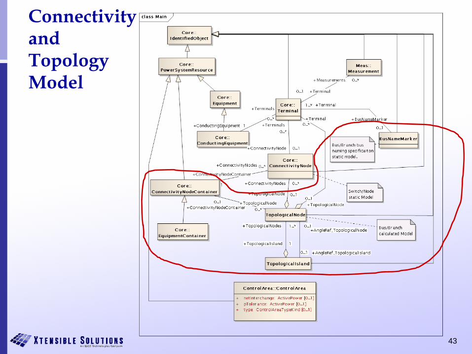
ConnectivityandTopology Model
44
Converting a Circuit to CIM Objects
• Example to show how voltage levels, current transformers, power transformers and generators are modelled
• Circuit contains a single generating source, load, line and busbar. The circuit also contains two power transformers resulting in three voltage levels of 17kV, 33kV and 132kV
Taken from Alan McMorran, Common Information Model Primer: First Edition., EPRI, Palo Alto, CA: 2011, 1024449
45
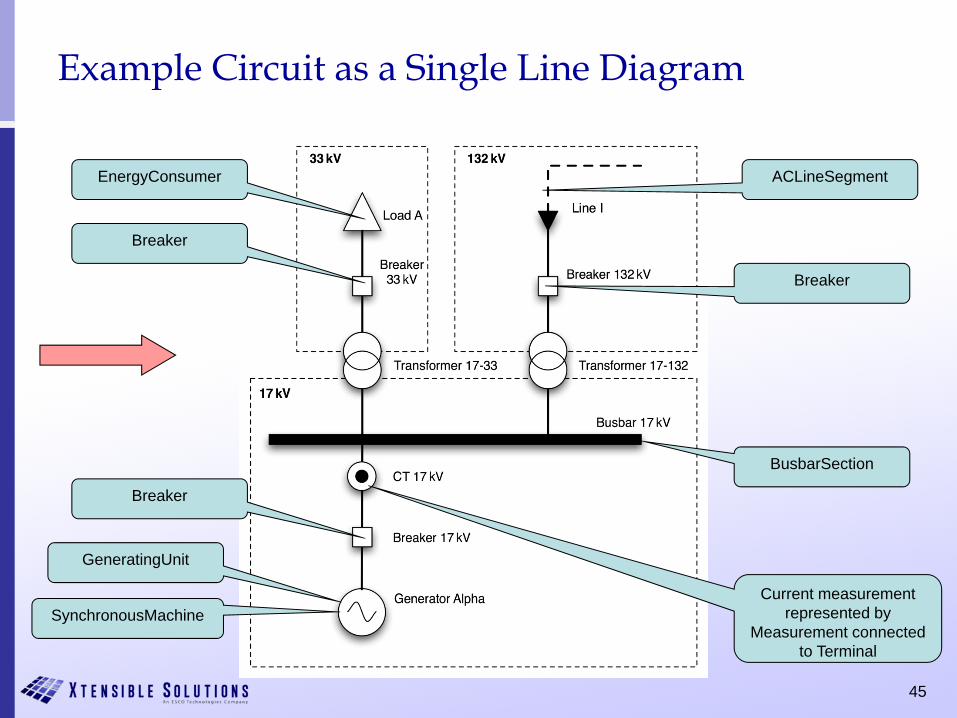
Example Circuit as a Single Line Diagram
EnergyConsumer
Breaker
SynchronousMachine
GeneratingUnit
Breaker
BusbarSection
Breaker
ACLineSegment
Current measurement represented by
Measurement connected to Terminal
46
Representing a Power Transformer as CIM Objects
• A power transformer is not mapped to a single CIM class– Represented by a number of classes– Two-winding power transformer becomes two
TransformerWinding objects within a PowerTransformer container
• If a tap changer is present to control one of the windings– An instance of the TapChanger class is associated with that
particular winding– Also contained within the PowerTransformer instance
47
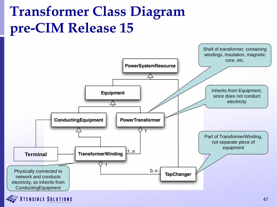
Transformer Class Diagrampre-CIM Release 15
Inherits from Equipment, since does not conduct
electricity
Physically connected to network and conducts
electricity, so inherits from ConductingEquipment
Part of TransformerWinding, not separate piece of
equipment
Shell of transformer, containing windings, insulation, magnetic
core, etc.
Terminal
48
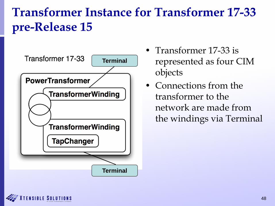
Transformer Instance for Transformer 17-33pre-Release 15
• Transformer 17-33 is represented as four CIM objects
• Connections from the transformer to the network are made from the windings via Terminal
Terminal
Terminal
49
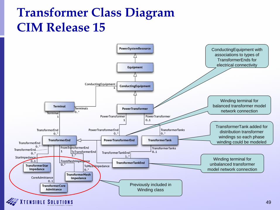
Transformer Class DiagramCIM Release 15
Winding terminal for balanced transformer model
network connection
Winding terminal for unbalanced transformer
model network connection
ConductingEquipment with associations to types of
TransformerEnds for electrical connectivity
TransformerTank added for distribution transformer windings so each phase
winding could be modeled
Previously included in Winding class
50
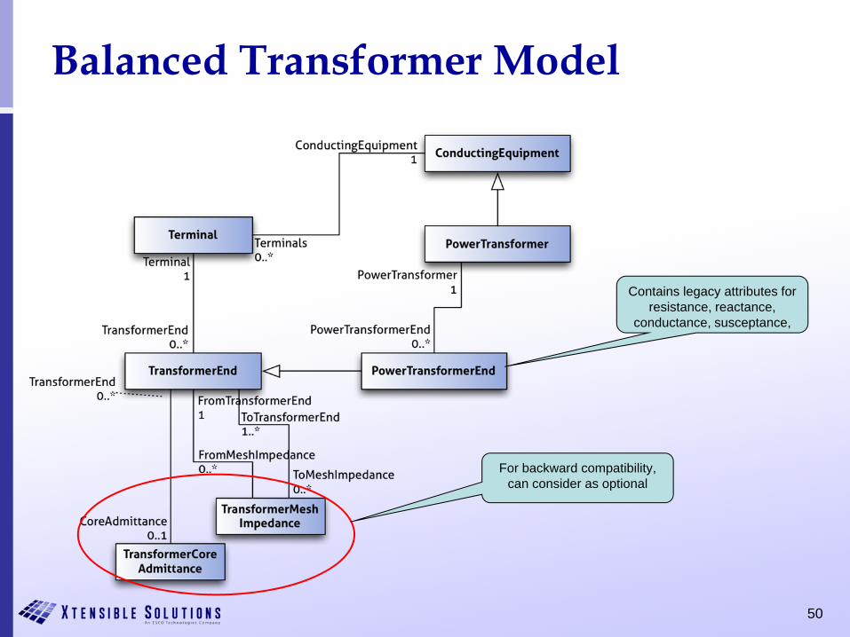
Balanced Transformer Model
Contains legacy attributes for resistance, reactance,
conductance, susceptance,
For backward compatibility, can consider as optional
51
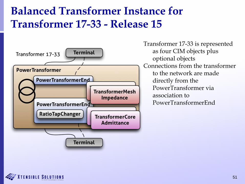
Balanced Transformer Instance for Transformer 17-33 - Release 15
Transformer 17-33 is represented as four CIM objects plus optional objects
Connections from the transformer to the network are made directly from the PowerTransformer via association to PowerTransformerEnd
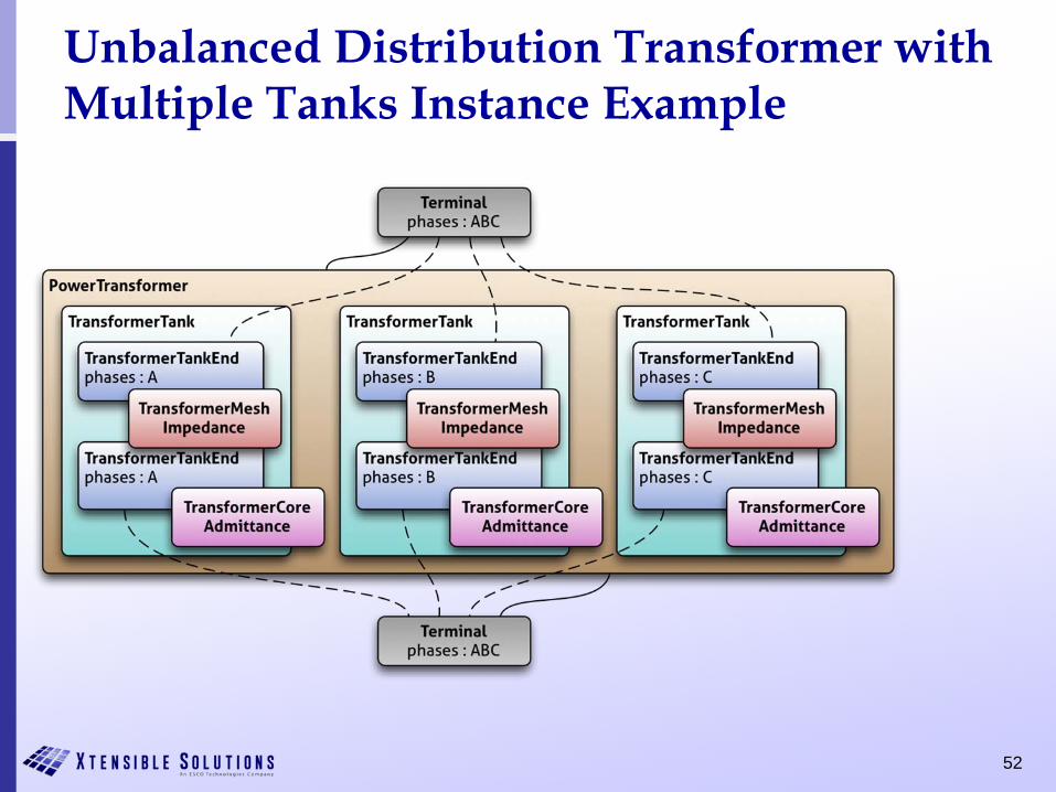
52
Unbalanced Distribution Transformer with Multiple Tanks Instance Example
53
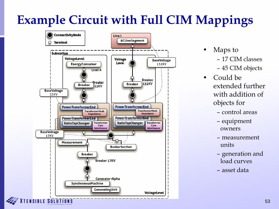
Example Circuit with Full CIM Mappings
• Maps to– 17 CIM classes– 45 CIM objects
• Could be extended further with addition of objects for
– control areas– equipment
owners– measurement
units– generation and
load curves– asset data
54
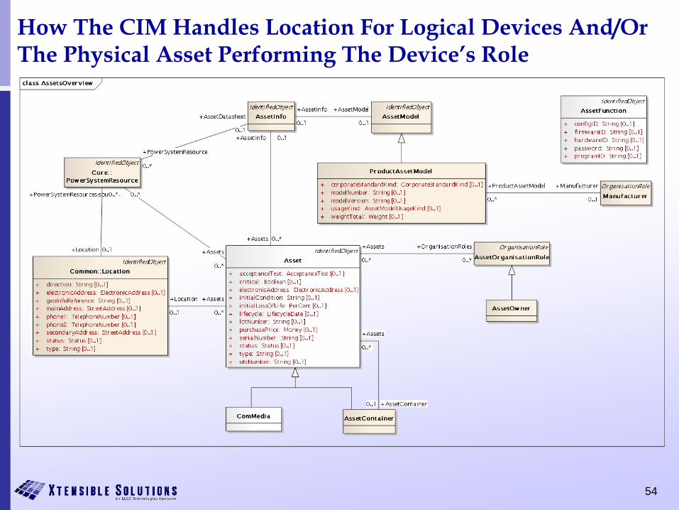
How The CIM Handles Location For Logical Devices And/OrThe Physical Asset Performing The Device’s Role
55
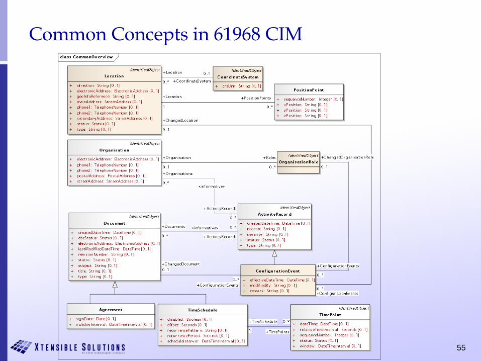
Common Concepts in 61968 CIM
56
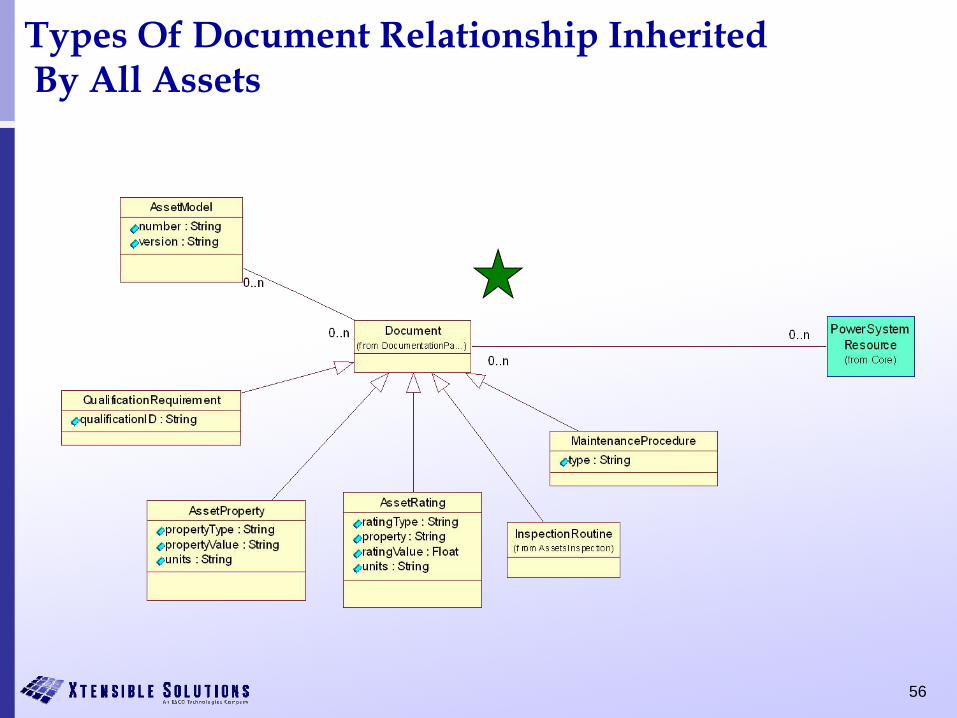
Types Of Document Relationship InheritedBy All Assets
57
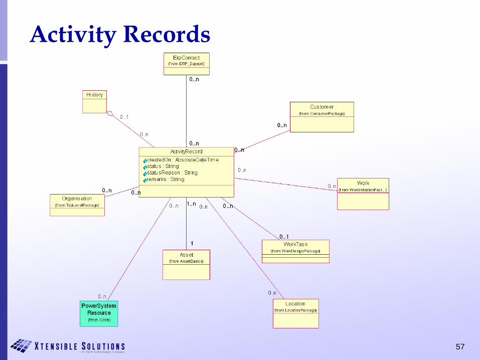
Activity Records
58
CIM UML Release Cycles
• 61970 CIM UML tries for annual release cycle• Basis for IEC 61970-301 CIM Base Fifth Edition
• Word document auto-generated from the UML electronic model• Information system and Profile documents are synchronized with
UML model release• 61968 CIM UML different update cycles
• Basis for IEC 61968-11 CIM Distribution Information Exchange Model
• 62325 CIM UML on another update cycle• Basis for IEC 62325-301 CIM for Deregulated Markets
• Complete CIM UML available as a combined model on CIMugSharepoint site:
– Title: draft CIM16 + DCIM12 + MCIM02
– Name: iec61970cim16v13_iec61968cim12v05_iec62325cim02v05
59
CIM UML in Enterprise Architect
• The CIM UML model is maintained in Sparx Enterprise Architect (EA)
• Current Official CIM Release 15 UML Model – iec61970cim15v33_iec61968cim11v13_iec62325cim01v07
• Go to UML model in EA
60
• End of presentation