Welcome to AIS Concepts and Changes - National Marine ... 2014 conference ais seminar... · Welcome...
55
Welcome to AIS Concepts and Changes Rich Beattie Oak Harbor Consulting LLC Sanibel Florida
Transcript of Welcome to AIS Concepts and Changes - National Marine ... 2014 conference ais seminar... · Welcome...
Welcome to AIS Concepts and Changes
Rich Beattie
Oak Harbor Consulting LLC
Sanibel Florida

An automated autonomous system for the exchange of navigational information
between suitably equipped vessels, aids to navigation and shore stations using 27
(currently) distinct messages and operating on two designated marine VHF channels.
There are two equipment Classes – A and B - which have distinct differences.
What is AIS?
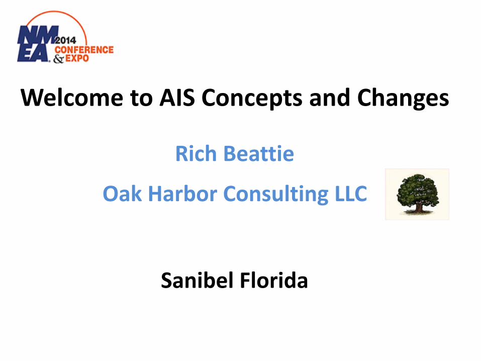
AIS Reports
Ship to ShipAIS Reports
AIS Reports
VTSControlCenter
Port Info
Port Info
Local Data(Tides, Current,Weather)
DGPSCorrections
Administration(Pilots, BerthAssignments)

Why do we need AIS?
Creates a much improved situational awareness for the Navigators by
overcoming the inherent limitations of sight, VHF voice and radar for collision avoidance – regardless of vessel size. In addition, with the ever increasing enhancements of AIS, the information
readily available to the Navigator is superior to past methodologies.

How does AIS work?
The heart of the system is a transmission protocol called Self Organizing Time Division Multiple Access (SOTDMA).
This protocol is what allows AIS to be autonomous and continuously
operational.

A ... A C B
... C B
C
A
60 Seconds 2250 Slots
26.67 ms 1 Slot = 256 Bits
AIS-1 161.975
AIS-2 162.025
Identity Position Speed over Ground Course over Ground Heading Rate of Turn Navigation Status Time Stamp
SOTDMA
A
B
C

ITDMA – Incremental TDMA A variant used during the first frame phasing and during
a change of Reporting Rate by the vessels
RATDMA – Random TDMA The protocol used to broadcast additional position
reports
FATDMA – Fixed TDMA The protocol used by Shore Station messages and
Aids To Navigation (e.g. buoys)

This is a Class B protocol where the transponder is ‘listening’ for the absence of
a carrier in a slot before it will transmit.
The fundamental idea is to ensure that the Class B transmissions are ‘polite’ and
secondary to the Class A transmissions.
Carrier Sense TDMA

2 to 10 second Tx interval while underway dependent on speed
3 Minutes Tx interval while at Anchor
Supplemental (Static) Data at 6-minute Intervals
12.5 watt transmitter
Class A transponders

Two types of units – one uses CSTDMA
and the other uses SOTDMA
The transmitter outputs of both units are lower than for a Class A unit
The TX intervals for moving vessels are also different
Class B transponders


• Latitude (both Classes) • Longitude (both Classes) • Speed over Ground (both Classes) • Course over Ground (both Classes) • Position Accuracy (both Classes) • Time Stamp (both Classes) • MMSI Number (both Classes) • True Heading (A requirement - B optional) • Rate of Turn (class A only) • Navigation Status (class A only) • DSC receiver fitted Y/N? (Class B only)
AIS Dynamic & Nav Status Broadcasts (variable times)

AIS Static & Nav Info Broadcasts (6 minutes)
• MMSI (both Classes) • Radio Call Sign (both Classes) • Name (both Classes) • Type of Ship/Cargo (both Classes) • Dimensions of Ship (both Classes) • Location of Reference Point (both Classes) • IMO Number (class A only) • Type of Position Fixing Device (class A only) • Draught of Ship (class A only) • Destination (class A only) • ETA at Destination (class A only) • Vendor ID (class B only)

U.S. Carriage Requirements
Vessels on International Voyages Self-propelled, > 65 Feet (Except Fishing or Small Passenger Vessels) Tankers Passenger Vessels > 150 Gross Tons Any Other Vessel > 300 Gross Tons (SOLAS)
Vessels Transiting VTS Areas
Self-propelled, > 65 Feet (Other Than Fishing or Small Passenger Vessels) Towing Vessels > 26 Feet and > 600 Horsepower Passenger Vessels > 150 Gross Tons

Installations
IMO SN Circular 227

Installation Considerations
VHF Antennas and cabling GPS Antennas Equipment Interfaces and cabling Ship’s Power Sources and cabling Pilot Plugs and AC power

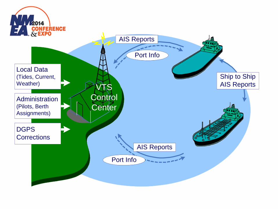
VHF Antennas
The AIS frequencies are on the high end of the VHF-FM band (@ 162 mhz). Because of this, the majority of standard marine VHF antennas are not manufactured for optimum performance at those frequencies.
VHF Antennas
VHF Antenna Possibly Integrated GPS
Antenna 6’ Feet from Conductive
Objects Ideally 6’ Directly above
or below VHF Otherwise 30’ Horizontal
Separation
6' Minimum
Main VHF Antenna
AIS VHF Antenna

VHF Antennas

VHF Antenna Cables
The IMO Safety Nav Circular 227 recommends the use of RG-214 coax which is a double screened coax cable which has better shielding capabilities (only 3% more than RG-8). As a matter of comparison, here are the four common types: RG-58 @ 50 ft 3.0 db loss 50% loss RG-8 Mini @ 50 ft 2.3 db loss 40% loss RG-8 @ 50 ft 1.2 db loss 20% loss RG-214 @ 50 ft 1.2 db loss 20% loss

GPS Antennas
The suggested mounting is one which gives a complete sky view from 5 degrees above the horizon to 90
degrees (the zenith).

GPS Antennas
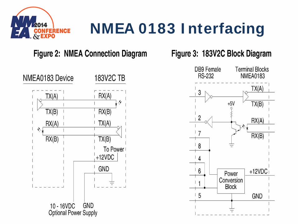
NMEA 0183 Interfacing

NMEA 0183 Interfacing
RS232 to RS485 Converter Wiki by Magneto Tech Research

Interface Cabling
All interconnection cables used to interface NMEA 0183 inputs from external GPS units, Gyrocompasses, Satellite Compasses, Speed Logs, and the like should use shielded
pair type cables.

Ship’s Power
For Class A systems, the IMO recommendation SN Circ. 227 is that the unit should be connected to an Emergency Source.
For IMO vessels, this means the Emergency Generator to which all the Communication and Navigation equipment is to be connected.
In addition, an Supplement to the Recommendation also requests
that the AIS be connected to a UPS to ensure that the 45 second switchover from Main to Emergency does not reset the AIS.
For non-IMO vessels – in light of the increased reliance on AIS units,
I would suggest that the AIS unit be connected to a battery.

Ship’s Power Cabling
DC voltage drops <3% Class A units: ~5 A @ 24 vdc 10 awg for 50 ft Class B units: ~2 A @ 12 vdc 14 awg for 25 ft

Pilot Plugs
Pin Signal
1 Transmit A
4 Transmit B
5 Receive A
6 Receive B
9 Shield
Required for Class A – Ships on International Voyages

Pilot Plugs
Also required for U.S. Flag Ships over 1600 GT
Required for IMO Ships using the Panama Canal and the St. Lawrence Seaway Canal

Pilot Plugs
Credit to Marimatech website

Configuration

Configuration
Data NMEA 0183 Sentence Format
Reference Datum DTM
Positioning System: Time of Position, Latitude / Longitude, Position Accuracy
GNS, GLL
GGA, RMC
Speed over Ground (SOG) VBW VTG, OSD, RMC
Course over Ground (COG) RMC VTG, OSD
Heading HDT OSD
RAIM Indicator GBS
Rate of Turn (ROT) ROT
Preferred Acceptable
NMEA Input Sentences for Class A units

Configuration
Vessel Data
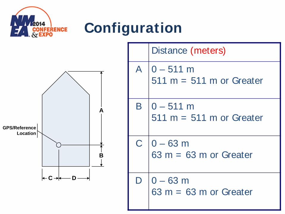
Maritime Mobile Service Identity (MMSI) Number Vessel Name Vessel Type and Cargo Type GPS Antenna Location/Reference Position/ Dimensions (in meters!) IMO Number (Class A fittings) Radio Call Sign (if assigned)
Configuration
A
B
DC
GPS/ReferenceLocation
Distance (meters)
A 0 – 511 m 511 m = 511 m or Greater
B 0 – 511 m 511 m = 511 m or Greater
C 0 – 63 m 63 m = 63 m or Greater
D 0 – 63 m 63 m = 63 m or Greater
Configuration
As the final check of the system, make sure that you have entered all the Static information correctly.
Confirm with another vessel or shore station that they can
receive ALL your vessel’s info correctly and that you are seeing others as well before you leave the vessel.
USCG Alert # 05-10
AIS is only as good as the information provided and exchanged, therefore, users must ensure their unit is always in effective operating condition and broadcasting accurate information

Configuration
Take the time to teach the Customer how to operate the AIS and how to decipher what it is telling the
Navigator.
Don’t assume they will ‘figure it out’ – especially when they get into the Voyage data fields
(destinations, cargo type, etc.)
Remind them that it is an AID to navigation

Application Specific Messages (ASM)
& Aids To Navigation
(ATON)
AIS Enhancements

Examples of ASMs
Wind Information Message Weather Station Message
Water Level Message Estimated Lock Times Message
Water Flow Message
AIS Enhancements

Tidal Information Sensor and ASM Broadcast Station
Transmitted every 3 minutes or as needed

Types of AIS ATONs
Real AIS ATONs – physical with a transponder fitted Synthetic AIS ATONs – physical with Base Station ID transmission overlay (not recommended for floating ATONs) Virtual AIS ATONs – non-existent with Base Station ID transmission overlay (envisioned for temporary use)
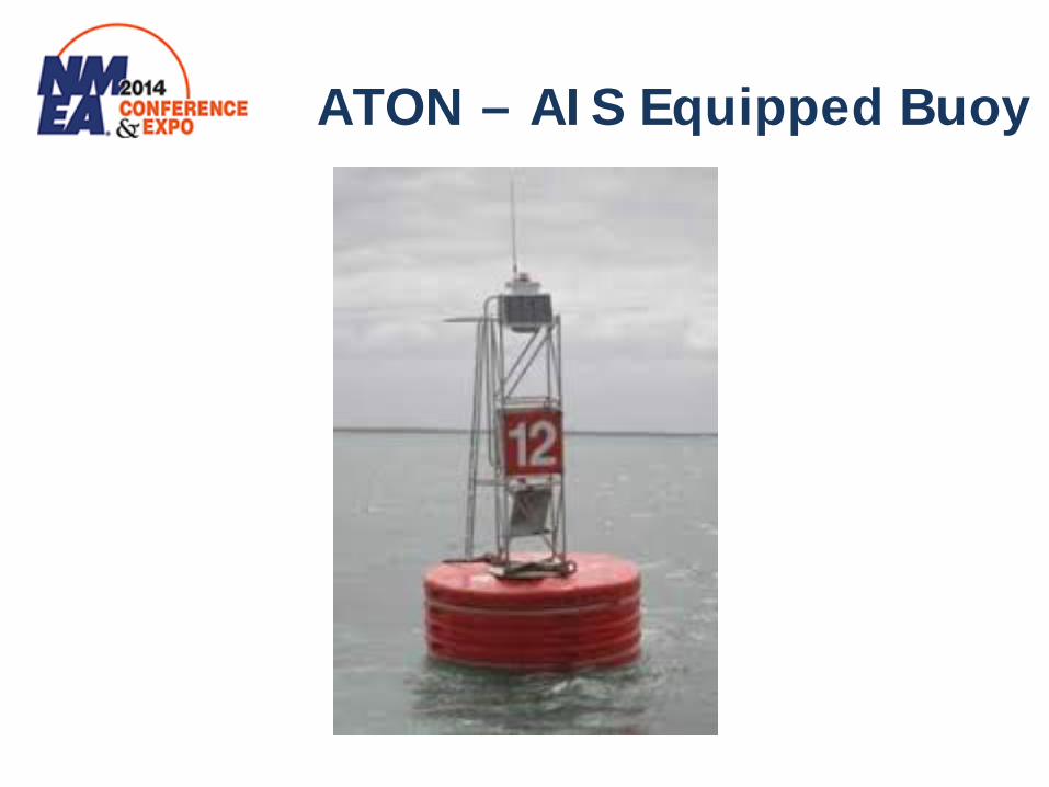
ATON – AIS Equipped Buoy

San Francisco ATON AIS Broadcasts

NOLA Bridge Construction ATON Broadcasts

AIS Surveillance
Maritime Awareness Security and Defense Issues Environmental Protection Search and Rescue Support Public Service to our Industry

AIS Surveillance

AIS Surveillance
Popular AIS Monitoring Services
Marine Traffic (Free – Terrestrial)
AIS Live (Fee – Terrestrial and Sat)
VesselFinder (Free – Terrestrial)
ShipFinder (Free – Terrestrial)

AIS Surveillance
AIS Surveillance
International Space Station

AIS Surveillance
AIS Reception from Space in 2010

AIS Surveillance
Space Based AIS Monitoring Services
ORBCOMM
exactEarth
SpaceQuest

AIS Surveillance
SpaceQuest AprizeSat Microsatellite Bus •Low Cost, High Performance •5 Year Mean Mission Duration •13 kg, 25 cm cube •20 Watts of Solar Power •1 Watt Bus Power Consumption •3 CPUs, 12 RXs, 3 TXs, 12 ANTs •Inexpensive Piggyback Launch •Autonomous Operation

Website Resources
www.navcen.uscg.gov www.iala-aism.org
www.imo.org www.nmea.org

Questions?