WEIGHT OPTIMIZATION OF STEERING KNUCKLE FOR · PDF fileInternational Research Journal of...
7
International Research Journal of Engineering and Technology (IRJET) e-ISSN: 2395 -0056 Volume: 03 Issue: 10 | Oct -2016 www.irjet.net p-ISSN: 2395-0072 © 2016, IRJET | Impact Factor value: 4.45 | ISO 9001:2008 Certified Journal | Page 294 WEIGHT OPTIMIZATION OF STEERING KNUCKLE FOR FOUR WHEELERS , 1 M.Tech (Machine Design), B.L.D.E.A’s V. P. Dr.P.G.H College of Engineering and Technology, Vijayapur, Karnataka, India 2 Professor, Dept. of Mechanical Engineering, B.L.D.E.A’s V. P. Dr.P.G.H College of Engineering and Technology, Vijayapur, Karnataka, India --------------------------------------****------------------------------------- Abstract - One of the main parts of vehicle is steering knuckle and it is a non standard component linking the suspension, steering and braking systems as well as the wheel hub to chassis of a vehicle. It is subjected to different loading under different circumstances, however not affecting the steering performance of the vehicle and other characteristics. Now a days, due to safety features and additional luxury, the vehicle’s weight is increasing. Increase of the vehicle’s weight affect’s the fuel efficiency and overall performance of the vehicle. Therefore to increase efficiency and to reduce fuel consumption of the vehicle, weight reduction of the vehicle plays very vital role. And the main objective is to reduce the weight of the vehicle, without compromising the strength with different materials. And this can be achieved by two steps. The first step is modeling the knuckle and determination of loads acting on it. And for this, finite element software is utilized. For optimization, ABAQUS, NASTRAN are being utilized. Meshing is done by HYPERMESH software. The crucial second step is analyzing the stresses and design adjustments for reducing the weight. It is found that there is substantial reduction in weight of the steering knuckle. Key Words: Steering knuckle, optimization, Weight reduction, Von-Mises stress, FEA. 1. INTRODUCTION The below fig-1 shows the steering knuckle. For study, steering knuckle was used as component in this investigation. It is the connection between stub axle, tie rod and axle housing. And by using king pin, it is connected to axle housing. Another end is connected to the tie rod. And with the help of the bearing over the knuckle, the wheel hub is fixed. Depending upon the suspension, brake and steering of the subassembly design of a particular vehicle, a knuckle is designed and hence it gives flexibility to optimize in terms of durability and weight. Now a days, in car manufacturing industries, weight reduction has become one of the important issues. Inspite of large design variations, steering knuckles are divided into two main types- with a hub or with a spindle. In suspension system, steering knuckle is one of the important parts amongst the vehicle structural components. When it is driven on a rough road, steering knuckle plays a very vital role in minimizing the vertical and roll motion of the vehicle body. First the steering knuckle is modeled by using the software HYPERMESH, which is excellent preprocessing software, which enables the modeling simple, easy and user friendly. And next, the model is imported in ABAQUS. And from ABAQUS, the part is analyzed in three steps. First step is pre-processing, second is solution and running and the third is post-processing. In first step, i.e., pre-processing, cleaning of the geometric model, definition of elemental property and meshing is done. And in second step, solution’s involving boundary conditions and nodes are applied and finally the solution is made to run. In the third step, results are analyzed by plotting different factors like stress, Von-Mises stress and so on. Fig- 1: Steering knuckle 2. OBJECTIVES AND PROBLEM DEFINITION 2.1 OBJECTIVES To find the structural strength and weight optimization of the steering knuckle at wheel hub. To alter the material properties i. e, from Cast Iron to Alumimium and check the weight to strength ratio. To compare the results by using a first order and second order elements.
Transcript of WEIGHT OPTIMIZATION OF STEERING KNUCKLE FOR · PDF fileInternational Research Journal of...

International Research Journal of Engineering and Technology (IRJET) e-ISSN: 2395 -0056
Volume: 03 Issue: 10 | Oct -2016 www.irjet.net p-ISSN: 2395-0072
© 2016, IRJET | Impact Factor value: 4.45 | ISO 9001:2008 Certified Journal | Page 294
WEIGHT OPTIMIZATION OF STEERING KNUCKLE FOR FOUR WHEELERS
,
1M.Tech (Machine Design), B.L.D.E.A’s V. P. Dr.P.G.H College of Engineering and Technology, Vijayapur, Karnataka, India
2Professor, Dept. of Mechanical Engineering, B.L.D.E.A’s V. P. Dr.P.G.H College of Engineering and Technology, Vijayapur, Karnataka, India
--------------------------------------****-------------------------------------
Abstract - One of the main parts of vehicle is steering knuckle and it is a non standard component linking the suspension, steering and braking systems as well as the wheel hub to chassis of a vehicle. It is subjected to different loading under different circumstances, however not affecting the steering performance of the vehicle and other characteristics. Now a days, due to safety features and additional luxury, the vehicle’s weight is increasing. Increase of the vehicle’s weight affect’s the fuel efficiency and overall performance of the vehicle. Therefore to increase efficiency and to reduce fuel consumption of the vehicle, weight reduction of the vehicle plays very vital role. And the main objective is to reduce the weight of the vehicle, without compromising the strength with different materials. And this can be achieved by two steps. The first step is modeling the knuckle and determination of loads acting on it. And for this, finite element software is utilized. For optimization, ABAQUS, NASTRAN are being utilized. Meshing is done by HYPERMESH software. The crucial second step is analyzing the stresses and design adjustments for reducing the weight. It is found that there is substantial reduction in weight of the steering knuckle.
Key Words: Steering knuckle, optimization, Weight reduction, Von-Mises stress, FEA.
1. INTRODUCTION
The below fig-1 shows the steering knuckle. For study, steering knuckle was used as component in this investigation. It is the connection between stub axle, tie rod and axle housing. And by using king pin, it is connected to axle housing. Another end is connected to the tie rod. And with the help of the bearing over the knuckle, the wheel hub is fixed. Depending upon the suspension, brake and steering of the subassembly design of a particular vehicle, a knuckle is designed and hence it gives flexibility to optimize in terms of durability and weight. Now a days, in car manufacturing industries, weight reduction has become one of the important issues. Inspite of large design variations, steering knuckles are divided into two main types- with a hub or with a spindle. In suspension system, steering
knuckle is one of the important parts amongst the vehicle structural components. When it is driven on a rough road, steering knuckle plays a very vital role in minimizing the vertical and roll motion of the vehicle body. First the steering knuckle is modeled by using the software HYPERMESH, which is excellent preprocessing software, which enables the modeling simple, easy and user friendly. And next, the model is imported in ABAQUS. And from ABAQUS, the part is analyzed in three steps. First step is pre-processing, second is solution and running and the third is post-processing. In first step, i.e., pre-processing, cleaning of the geometric model, definition of elemental property and meshing is done. And in second step, solution’s involving boundary conditions and nodes are applied and finally the solution is made to run. In the third step, results are analyzed by plotting different factors like stress, Von-Mises stress and so on.
Fig- 1: Steering knuckle
2. OBJECTIVES AND PROBLEM DEFINITION
2.1 OBJECTIVES
To find the structural strength and weight optimization of the steering knuckle at wheel hub.
To alter the material properties i. e, from Cast Iron to Alumimium and check the weight to strength ratio.
To compare the results by using a first order and second order elements.

International Research Journal of Engineering and Technology (IRJET) e-ISSN: 2395 -0056
Volume: 03 Issue: 10 | Oct -2016 www.irjet.net p-ISSN: 2395-0072
© 2016, IRJET | Impact Factor value: 4.45 | ISO 9001:2008 Certified Journal | Page 295
2.2 PROBLEM DEFINITION
As motor vehicles required today to have greater speed and power, it’s steering knuckle have greater strength and rigidity, but it should be lighter in weight and size. In vehicle output growth, significance is given to the heaviness of the linier and angular parts that steering knuckle, tie rod pitman arm. On the whole system, performance is affected by the higher steering inertia forces generated by the moving parts of the vehicle. Therefore, the investigation to avoid any failures in the car over long term is made.
The main problems that are found in the manufacturing of the knuckle are as follows.
1. Because of varying stress distribution, the life of the steering knuckle is reduced.
2. The overall performance of the vehicle may be affected by this.
The wastage of material may occur, because of lack of knowledge of the tension or stress distribution. For weight optimization of steering knuckle, it is necessary that one should look into the aspects of design and the available literature for understanding the industries need for the reduction of weight of the components and to establish the increasing FEA’s role for the same as a tool. The available literature has increased the multifold and multi forms of design structures, FEA methods over the past decade and optimization techniques have emerged
3. METHODOLOGY
Fig-2: Flow chart of methodology
The above fig-2 shows the flow chart of methodology used for steering knuckle. Some of them are explained below.
3.1 DESIGNING A CAD MODEL:
By using the 3D modeling software CATIA, CAD model of
steering knuckle is developed. And it consists of a
steering tie-rod and many other mounting points, stub
hole. Design of the knuckle depends on geometry of
suspension and steering.
3.2 SELECTION OF MATERIAL:
There are different types of materials which can be used for the manufacturing of steering knuckle as s. g. Iron (ductile iron), white Cast-Iron, grey Cast Iron and Aluminium. But grey cast iron alloy is used for this work.
3.3 MESHING:
CAD model of knuckle is then transformed into STEP file. And this model is imported in HYPERMESH workbench recreation. And prior to the meshing of model, geometry cleanup must be performed. ABAQUS is used as solver. To get the best quality mesh, fine element size is selected.
Fig-3.3.1: Detail and meshing of steering knuckle
The above fig-3.3.1 shows detail and meshing of steering knuckle. 4. MATERIAL DETAILS 4.1 ALUMINIUM PROPERTIES
Density ρ = 2.6898 g/cm3 Yield strength Sy = 240 Mpa
Young’s modulus or modulus of elasticity
E = 7x10⁵ Mpa
Poisson’s ratio ν = 0.34 Table - 1: Properties of Aluminium
Start
Import CAD Model
Shape Optimization
Mesh 3D Model
Liner FE Modeling
Executive Liner
Static Analysis
Optimized Model
Validate
Initial Model and
Result
Stop
No
Yes
Compare with initial
Model

International Research Journal of Engineering and Technology (IRJET) e-ISSN: 2395 -0056
Volume: 03 Issue: 10 | Oct -2016 www.irjet.net p-ISSN: 2395-0072
© 2016, IRJET | Impact Factor value: 4.45 | ISO 9001:2008 Certified Journal | Page 296
The above table-1 shows the properties of Aluminum such as Density, Yield strength, Young’s modulus, Poisson’s ratio.
4.2 CAST IRON PROPERTIES
Density ρ = 7.2 g/cm3
Yield strength Sy = 98-280 Mpa Young’s modulus or modulus of elasticity
E = 110x103 Mpa
Poisson’s ratio ν = 0.26
Table – 2: Properties of Cast Iron
The above table-2 shows the properties of Cast Iron such as Density, Yield strength, Young’s modulus, Poisson’s ratio.
7. LOADS AND BOUNDARY CONDITIONS
Fig-7.1: Applied boundary condition
The above fig-7.1 shows the boundary conditions applied for steering knuckle and here all degrees of freedom are fixed.
Fig -7.2: Loads generated on steering
knuckle
The above fig-7.2 shows loads generated on steering knuckle (applied load).
The forces encountered on this steering knuckle are
1. Axial load: when the car is moving, if I apply a load, then there will be axial inertia load coming on the front wheels in x-axis.
2. Lateral load: If the car is moving, while taking a turn moment will be created. i.e., after shifting the C.G (centre of gravity) moment will be created.
5. RESULTS AND DISCUSSION
5.1 Using Cast Iron for steering knuckle.
5.1.1: [For 1st order load case 1(LC1) Cast Iron- 2.92kg]
Fig- 5.1.1: Steering knuckle made from Cast Iron
The above fig-5.1.1 shows steering knuckle which is made of Cast Iron. The max Von-Mises stress is 165 MPA and it is for 1st order LC1 Cast Iron.
5.2 Using Aluminium for steering knuckle.
5.2.1: [For 1st order Load case 1(LC1) Aluminium-1kg]
Fig- 5.2.1: Steering knuckle made from Aluminium
Connected to
58

International Research Journal of Engineering and Technology (IRJET) e-ISSN: 2395 -0056
Volume: 03 Issue: 10 | Oct -2016 www.irjet.net p-ISSN: 2395-0072
© 2016, IRJET | Impact Factor value: 4.45 | ISO 9001:2008 Certified Journal | Page 297
The above fig-5.2.1 shows steering knuckle made from Aluminium. Here the max Von-Mises stress is 165 MPA and it is for 1st order LC1 Aluminium.
5.3 Using Cast Iron for steering knuckle.
Fig- 5.3.1: for 1st order LC2 Cast Iron-2.92kg
Above fig-5.3.1 shows the max Von-Mises stress for 1st order LC2 Cast Iron and it is 336 MPA.
5.4 Using Aluminium for steering knuckle.
Fig- 5.4.1: for 1st order LC2 Aluminium-1kg
Above fig-5.4.1 shows the max Von-Mises stress for 1st order LC2 Aluminium which is 336 MPA.
5.5 Using Cast Iron for steering knuckle.
Fig- 5.5.1: for 2nd order LC1 cast-2.92kg
Above fig-5.5.1 shows the max Von-Mises stress for 2nd order LC1 Cast Iron and it is 237 MPA.
5.6 Using Aluminium for steering knuckle
Fig- 5.6.1: for 2nd order LC1 Aluminium-1kg
The above fig-5.6.1 shows max Von-Mises stress for 2nd order LC1 Aluminium which is 237 MPA.
5.7 Using Cast Iron for steering knuckle.
Fig- 5.7.1: for 2nd order LC2 cast iron-2.92kg
Above fig-5.7 shows the max Von-Mises stress for 2nd order LC2 Cast Iron which is 467 MPA.
5.8 Using Aluminium for steering knuckle
Fig 5.8.1: for 2nd order LC2 Aluminium-1kg
Above fig-5.8.1 shows the max Von-Mises stress for 2nd
order LC2 Aluminium and it is 237 MPA
International Research Journal of Engineering and Technology (IRJET) e-ISSN: 2395 -0056
Volume: 03 Issue: 10 | Oct -2016 www.irjet.net p-ISSN: 2395-0072
© 2016, IRJET | Impact Factor value: 4.45 | ISO 9001:2008 Certified Journal | Page 298
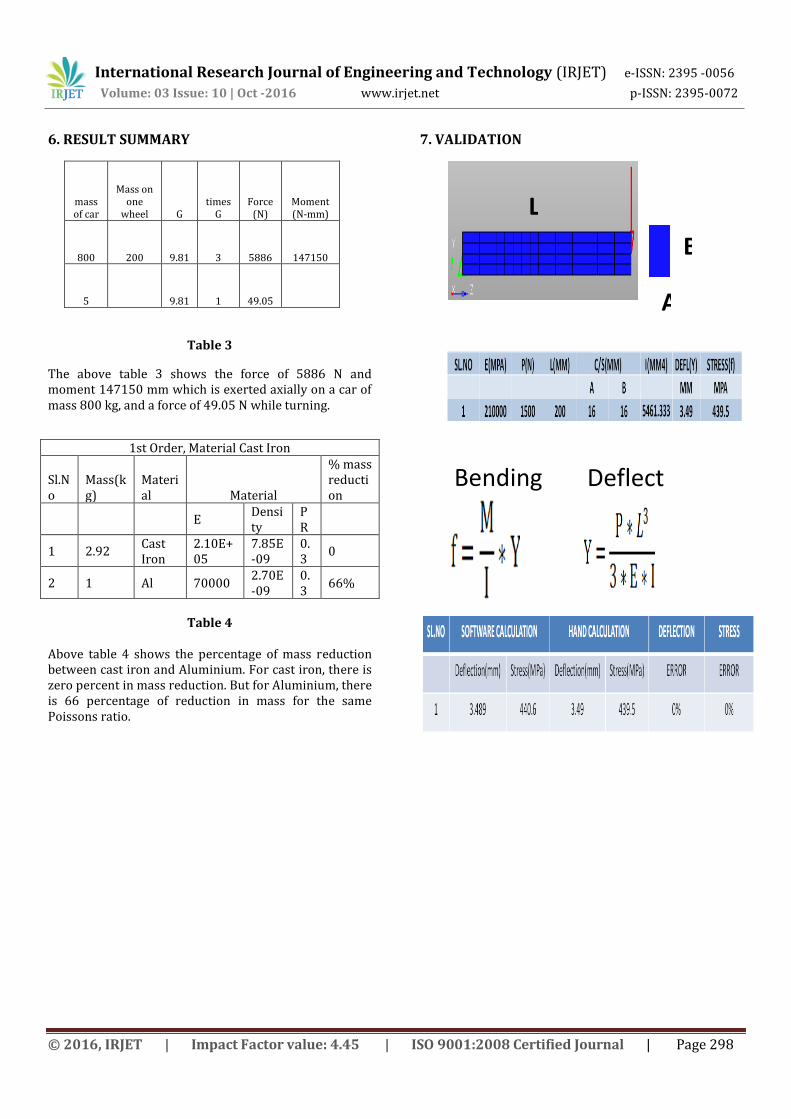
6. RESULT SUMMARY
mass of car
Mass on one
wheel G times
G Force
(N) Moment (N-mm)
800 200 9.81 3 5886 147150
5
9.81 1 49.05
Table 3
The above table 3 shows the force of 5886 N and moment 147150 mm which is exerted axially on a car of mass 800 kg, and a force of 49.05 N while turning.
Table 4
Above table 4 shows the percentage of mass reduction between cast iron and Aluminium. For cast iron, there is zero percent in mass reduction. But for Aluminium, there is 66 percentage of reduction in mass for the same Poissons ratio.
7. VALIDATION
1st Order, Material Cast Iron
Sl.No
Mass(kg)
Material Material
% mass reduction
E Density
PR
1 2.92 Cast Iron
2.10E+05
7.85E-09
0.3
0
2 1 Al 70000 2.70E-09
0.3
66%
L
B
A
Bending stress is
Deflection is

International Research Journal of Engineering and Technology (IRJET) e-ISSN: 2395 -0056
Volume: 03 Issue: 10 | Oct -2016 www.irjet.net p-ISSN: 2395-0072
© 2016, IRJET | Impact Factor value: 4.45 | ISO 9001:2008 Certified Journal | Page 299
Fig-7.1: Beam displacements
The above fig-7.1 shows the displacement of 3.489mm when a load of 1500 N is applied on a cantilever beam which has a length of 200mm
Fig-7.2: Max stress on Beam
The above fig-7.2 shows a max stress of 440.6 MPA when a load of 1500 N is applied on a cantilever beam which has a length of 200 mm.
Max stress: 440.6MPa
Max displacement: 3.489mm

International Research Journal of Engineering and Technology (IRJET) e-ISSN: 2395 -0056
Volume: 03 Issue: 10 | Oct -2016 www.irjet.net p-ISSN: 2395-0072
© 2016, IRJET | Impact Factor value: 4.45 | ISO 9001:2008 Certified Journal | Page 300
8. CONCLUSION AND FUTURE SCOPE OF PROJECT
8.1 CONCLUSION
The structural strength of steering knuckle at wheel hub is good and safe to manufacture with either Cast Iron or Aluminum.
As per strength is concerned, both materials are good. But with respect to weight to strength ratio, Aluminum is a better choice.
As per the order of element is concerned, it is better to use second order elements. Because second order elements contain more number of nodes than first order elements which gives good results.
There is substantial reduction in weight when Aluminum is used instead of Cast Iron. Reduction in weight is 66 percent.
8.2 FUTURE SCOPE OF PROJECT
Currently, the analysis is carried out on the topology optimization, but this will reduce the weight of the component. And there are still chances of stress concentration. Therefore shape optimization can be made to avoid this stress concentration. Similar to steering knuckle, weight optimization on other automobile components can be done to reduce weight and cost. This will overall reduce cost of the vehicle.
9. REFERENCES
1. A text book of “Machine Design” by Khurmi and Gupta.
2. A text book of “Finite element in engineering” by Tirupti R. chandrupatla and Ashok D. Belegunda, Third Edition, PHI learning Pvt. Ltd.
3. Dumbre, P., Mishra, A.K., Aher, V.S., and Kulkarni, S.S. (2014). Structural analysis of steering knuckle for weight reduction, International Journal of Advanced Engineering Research Studies, April-June.
4. Kulkarni, V. R. and Tambe, A. G., (2013): Optimization and Finite Element Analysis of Steering Knuckle, Altair Technology Conference.