
Weight and Balance User Guide - mygdc.com
39
Weight and Balance User Guide Selecting the Weight and Balance tab brings up the Departure and Destination screen, used for initiating the process for a standalone WB report. Select the tail to be used for the analysis from the Select Tail drop down menu. The next page displays the selections available including RA and WB. Select Weight and Balance – for running WB stand alone. The next page requires that the Departure and Destination airports must be entered, along with any Departure or Destination (2) Alternates, as applicable.
Transcript of Weight and Balance User Guide - mygdc.com

Weight and Balance User Guide Selecting the Weight and Balance tab brings up the Departure and Destination screen, used for initiating the process for a standalone WB report.
Select the tail to be used for the analysis from the Select Tail drop down menu.
The next page displays the selections available including RA and WB. Select Weight and Balance – for running WB stand alone.
The next page requires that the Departure and Destination airports must be entered, along with any Departure or Destination (2) Alternates, as applicable.

The WB Layout and Data Entry Screen is now displayed.
The Layout is a copy of the cabin configuration for the specific tail number. Typically, this diagram is submitted to Honeywell during account set-up. In addition, the following information, provided by the operator, is used to set-up the specific tail number:
Seat locations/arms,
The name, location/arms of all other pertinent areas that may be used for storage, i.e. Closets, Cabinets, Galley, FWD/Aft Cargo centroids, etc.

The Empty Weight and CG % MAC are the values provided by the operator and are be based upon the submitted WB Report. NOTE: if the aircraft is subsequently re-weighed, the revised WB Report should be forwarded to Honeywell so that the database may be updated. Pilot and Observer/Jumpseat weights may be defaulted to values provided by the operator during account set-up, as required.
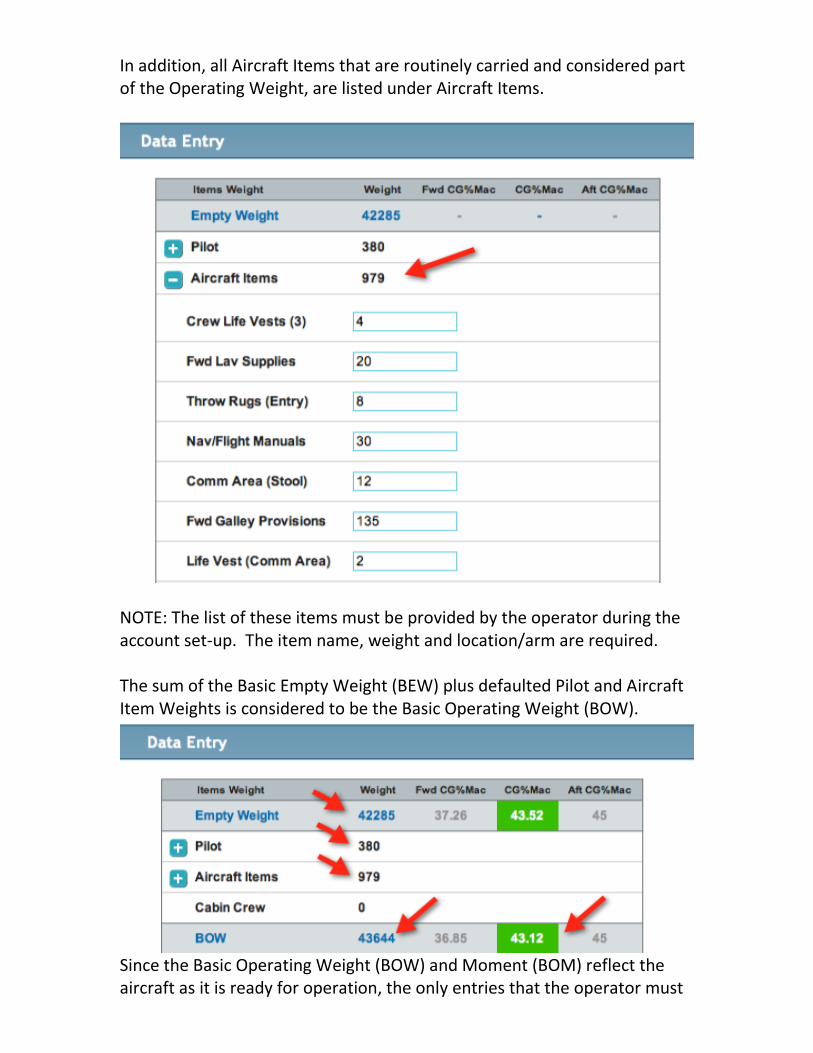
In addition, all Aircraft Items that are routinely carried and considered part of the Operating Weight, are listed under Aircraft Items.
NOTE: The list of these items must be provided by the operator during the account set-up. The item name, weight and location/arm are required. The sum of the Basic Empty Weight (BEW) plus defaulted Pilot and Aircraft Item Weights is considered to be the Basic Operating Weight (BOW).
Since the Basic Operating Weight (BOW) and Moment (BOM) reflect the aircraft as it is ready for operation, the only entries that the operator must

make for a flight are Passengers, Cargo and Fuel (Fuel load and Enroute burn). Passengers may be loaded into the system by either hovering over the selected seat and then selecting the desired weight from the drop down menu,

Or by expanding the Passenger section of the Data Entry field and then manually entering a value.
Either data entry method will display the value on the graphic and on the Data Entry screen.

Cargo may be entered in a similar manner; either by hovering over the cargo area on the graphic or expanding the Cargo field and manually entering the weight.
Fuel may be entered at any time. Expanding the Fuel field and entering the fuel on board at engine start.
The Taxi Fuel is a value that may be set as a default (done during account set-up) and/or entered by expanding the Taxi field and manually entering a value.
In a similar fashion, expand the Enroute field and enter the fuel burn.

The aircraft’s fuel weight limit is determined using the manufacturer’s volumetric limit of all tanks – in gallons – in combination with a standard density of 6.7 lb./gal. Since the aircraft’s fuel capacity is fixed in gallons, it is necessary to utilize a fixed density value so that calculations can accurately generate the fuel burn ‘vector’. The vector or burn curve is used to determine if the CG remains in or goes out-of-limit in-flight as the fuel is burned. Once the aircraft payload and fuel entries have been completed, select the Compute button and the weights and CG values will be calculated. NOTE: the Compute button may be used at any point during the loading process.
The CG Graph is displayed along with the TO Trim setting. If any limit, MTOW, MZFW, MLW or their respective CG value falls out-of-limits, the appropriate field will be noted and an ‘error message will appear. The out-of-limits condition must be cleared before the system will allow a Release to be prepared.

When the loading has been completed, Compute has been selected, and all computations within limits – select the Release button.
Complete the Load Manifest form as required and select the Release button on the pop-over window.

A two-page pdf report will be prepared which summarizes the aircrafts loading and CG values. All pages are watermarked with the aircraft’s registration number and date.


Integrated RA and WB Selecting the Integrated RA and WB tab brings up the RA screen, which is the first step initiating the process for an integrated RA and WB report. Integrated RA and WB tool incorporates all of the features available in the respective RA and WB stand-alone tools. The integrated solution also incorporates the Fuel Load and Fuel Burn calculations from the Flight Planning module into the WB module by pre-populating the respective fields on the Data Entry screen. The key benefit of using the integrated feature is the inclusion of the RA TO and LD performance calculations into the WB loading/calculation. By integrating these limits into the calculation, the solution not only checks that the MTOW, MZFW, MLW, and CG values throughout the flight are within limits but also assures that the planned load and fuel burn do not exceed the TO or LD performance limits. After completing the flight planning portion, complete the RA and WB in sequence to assure that the trip has been planned to meet the required fuel load and that the planned payload and fuel have been checked for WB compliance as well as for TO and LD performance limitations. The integration of the RA and WB screens allows movement from RA-to-WB and back while persisting and updating the calculations as necessary. This feature allows the operator to run ‘what if’ scenarios – such as changes to the environmental conditions, runway contaminants, payload etc. – to quickly determine the affect of these changes and to prepare contingency plans as required.

Having previously completed and saved a flight plan, from the Flight Plan drop down menu Select Review Flight Plans.
From the list of available flight plans select the desired flight for computing integrated RA and WB, and Select View More.
From the subsequent drop down, select RA and WB.

The RA page is displayed as the first step in completing the integrated solution.
Note that the page is similar to the stand alone RA page, with couple of differences. Since the TO and LD weights were estimated in the flight planning phase, those values have been carried over for reference in the RA calculations. The labels of these fields are “Flightplan Weight” and are highlighted with the arrows on the right. Also, the label for the weight entry field has been changed to Actual TO and LD Weight, noted by the arrows on the left. These two fields will be populated after the WB screen has been accessed and the TO and LD weights determined.

Starting with the Departure section of the screen, enter the departure airport ICAO identifier and then select a runway.
Tools are provided to assist completing the departure information. Airfield and Weather Information, including NOTAMS may be reviewed.

In addition, Runway Information, including Declared Distances and Engine Out Procedures, may be reviewed.
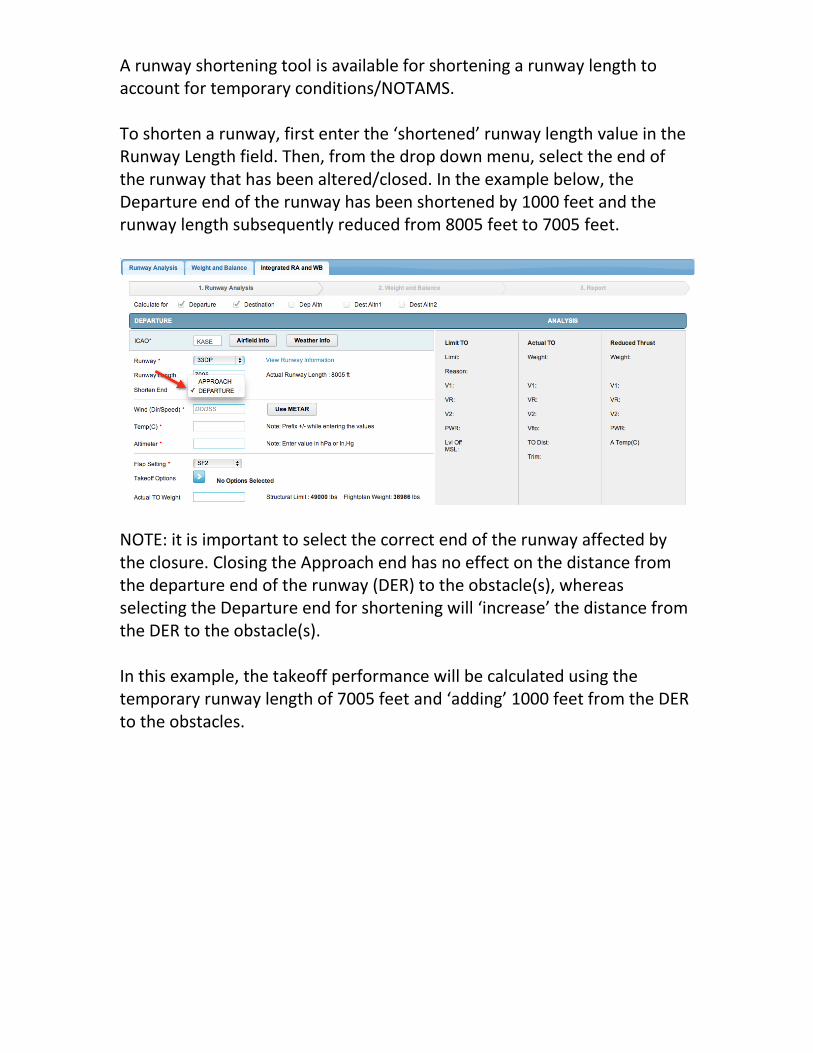
A runway shortening tool is available for shortening a runway length to account for temporary conditions/NOTAMS. To shorten a runway, first enter the ‘shortened’ runway length value in the Runway Length field. Then, from the drop down menu, select the end of the runway that has been altered/closed. In the example below, the Departure end of the runway has been shortened by 1000 feet and the runway length subsequently reduced from 8005 feet to 7005 feet.
NOTE: it is important to select the correct end of the runway affected by the closure. Closing the Approach end has no effect on the distance from the departure end of the runway (DER) to the obstacle(s), whereas selecting the Departure end for shortening will ‘increase’ the distance from the DER to the obstacle(s). In this example, the takeoff performance will be calculated using the temporary runway length of 7005 feet and ‘adding’ 1000 feet from the DER to the obstacles.
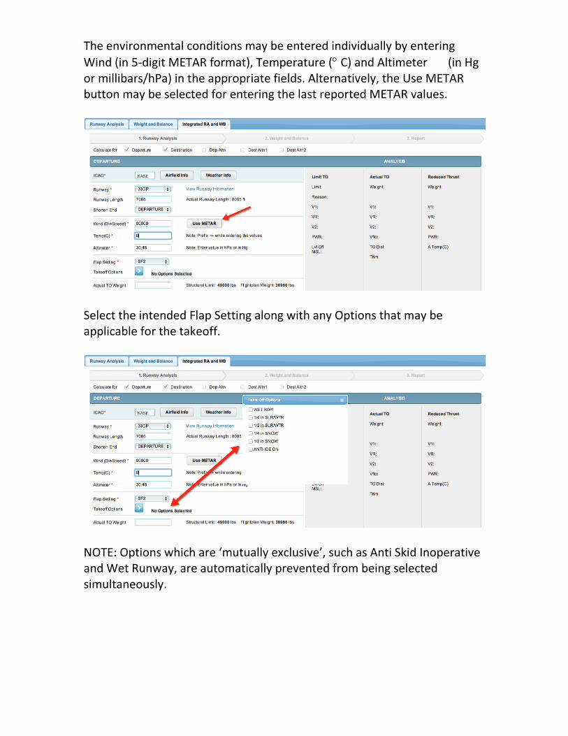
The environmental conditions may be entered individually by entering
Wind (in 5-digit METAR format), Temperature ( C) and Altimeter (in Hg or millibars/hPa) in the appropriate fields. Alternatively, the Use METAR button may be selected for entering the last reported METAR values.
Select the intended Flap Setting along with any Options that may be applicable for the takeoff.
NOTE: Options which are ‘mutually exclusive’, such as Anti Skid Inoperative and Wet Runway, are automatically prevented from being selected simultaneously.

Emergency Return (ER) may be selected, if desired. Select the landing runway and the desired flap setting.
When selecting Emergency Return, a report will be included in the release paperwork providing LD data for an immediate landing at the departure airport, for the calculated takeoff weight. The next step is to complete the Destination portion of the page.

Landing performance for the destination airfield requires similar entries as the departure data.
NOTE: Landing Options include the ability to select landing factor values of 60%, 80% or Unfactored. The selected landing factor will be used to determine the Limit LD Weight. The selection will also be used to determine if the weight of the aircraft entered for the landing Estimated Weight, will be able to stop within:
60% of the Landing Distance Available (LDA), or
80% of the LDA, or
Unfactored – using up to 100% of the LDA

Once all of the required entries have been made, select the Compute button to run the RA.
The calculated data will be displayed on the right side of the page, for the Limit TO/LD Weights. Since the Actual TO/LD Weights are not known until the WB page has been completed, performance data other than the limits, will not be displayed .

Limit TO The Limit TO field displays the takeoff performance Limit Weight, determined using the environmental conditions, flap and options selections for the departure airport. The limit Reason is also displayed denoting the factor determined to be the most limiting. Takeoff speeds V1, VR, V2, and VFTO are displayed for the Limit Weight. The power setting for the selected flap setting, environmental conditions and selected options (as required) is also displayed. The calculated Level Off Altitude (MSL) is displayed, defining the altitude to which the aircraft must climb to, level off, and accelerate in level flight to VFTO. Limit LD The Limit LD field displays the landing performance Limit Weight, determined using the environmental conditions, flap and options selections for landing at the destination airport. The limit Reason is also displayed denoting the factor most limiting for landing. NOTE: the limit weight is calculated using the selected Landing Factor option, i.e. when the limit Reason is Field Length, the aircraft can be stopped using all of the factored value of the LDA only when flown using the same technique as during the aircraft landing certification process (example: FAR 25.125). After computing the RA limits, select the Weight and Balance button.

The WB Layout and Data Entry Screen is now displayed.
Note that the Fuel and Enroute fields have been pre-populated with the fuel calculated in the flight planning module. In addition, the Flight plan Takeoff/Landing Weight values as determined during the flight planning phase are noted for reference during the loading phase of the flight. The Layout is a copy of the cabin configuration for the specific tail number. Typically, this diagram is submitted to Honeywell during account set-up. In addition, the following information, provided by the operator, is used to set-up the specific tail number:
Seat locations/arms,
The name, location/arms of all other pertinent areas that may be used for storage, i.e. Closets, Cabinets, Galley, FWD/Aft Cargo centroids, etc.


The Empty Weight and CG % MAC are the values provided by the operator and are be based upon the submitted WB Report. NOTE: if the aircraft is subsequently re-weighed, the revised WB Report should be forwarded to Honeywell so that the database may be updated. Pilot and Observer/Jumpseat weights may be defaulted to values provided by the operator during account set-up as required.

In addition, all Aircraft Items that are routinely carried and considered part of the Operating Weight, are listed under Aircraft Items.
NOTE: The list of these items must be provided by the operator during the account set-up. The item name, weight and location/arm are required. The sum of the Basic Empty Weight (BEW) plus defaulted Pilot and Aircraft Item Weights is considered to be the Basic Operating Weight (BOW).
Since the Basic Operating Weight (BOW) and Moment (BOM) reflect the aircraft as it is ready for operation, the only entries that the operator must

make for a flight are Passengers and Cargo (Fuel load and Enroute burn have been carried into the Data Entry from the flight planning module). Passengers may be loaded into the system by either hovering over the seat and selecting the desired weight from the drop down menu,

Or by expanding the Passenger section of the Data Entry field and manually entering a value.
Either data entry method will display the value on the graphic and on the Data Entry screen.

Cargo may be entered in a similar manner; either by hovering over the cargo area on the graphic or expanding the Cargo field and manually entering the weight.
Fuel has been pre-populated from the flight planning module.
The Taxi Fuel is included in the flight planning module and therefore is shown as zero. It cannot be modified.
In a similar fashion, enroute burn has been pre-populated from the flight planning module.

The aircraft’s fuel weight limit is determined using the manufacturer’s volumetric limit of all tanks – in gallons – in combination with a standard density of 6.7 lb./gal. Since the aircraft’s fuel capacity is fixed in gallons, it is necessary to utilize a fixed density value so that calculations can accurately generate the fuel burn ‘vector’. The vector or burn curve is used to determine if the CG goes out-of-limit in-flight as the fuel is burned. NOTE: Once the aircraft payload and fuel entries have been completed it would be advisable to crosscheck the WB determined TO and LD weights against the flight planning values. If there is significant difference, it may be necessary to rerun the flight plan or alter the actual load. Select the Compute button and the weights and CG values will be calculated. NOTE: the Compute button may be used at any point during the loading process.
The CG Graph is displayed along with the TO Trim setting. If any limit, MTOW, MZFW, MLW or their respective CG value falls out-of-limits, the appropriate field will be noted and an error message will appear. The out-of-limits condition must be cleared before the system will allow a Release to be prepared.

Select the ‘1. Runway Analysis’ to return to the RA screen.

Selecting the Compute button will now calculate the performance for the Actual Weights.
Limit TO The Limit TO field displays the takeoff performance Limit Weight, determined using the environmental conditions, flap and options selections for the departure airport. The limit Reason is also displayed denoting the factor determined to be the most limiting. Takeoff speeds V1, VR, V2, and VFTO are displayed for the Limit Weight. The power setting for the selected flap setting, environmental conditions and selected options (as required) is also displayed. The calculated Level Off Altitude (MSL) is displayed, defining the altitude to which the aircraft must climb to, level off, and accelerate in level flight to VFTO. Actual TO Similarly, the Actual TO field displays the takeoff performance data for takeoff at the Actual Weight value. In addition, the TO Distance and Trim are displayed. Reduced Thrust For those aircraft capable of takeoff at reduced thrust, performance data is provided. While similar to the Actual TO data, the Reduced Thrust data also includes the reduced thrust power setting and the assumed temperature. Limit LD The Limit LD field displays the landing performance Limit Weight, determined using the environmental conditions, flap and options selections for landing at the destination airport. The limit Reason is also displayed denoting the factor most limiting for landing. NOTE: the limit weight is calculated using the selected Landing Factor option, i.e. when the limit Reason is Field Length, the aircraft can be stopped using all of the factored value of the LDA only when flown using the same technique as during the aircraft landing certification process (example: FAR 25.125). Actual LD The Actual LD field displays the landing performance data for landing at the landing Actual Weight value. In addition, the LDA, actual landing distance (AFM actual landing distance – without factor), 115% of the actual landing distance (for compliance with FAA Safety Alert for Operators – SAFO 06012, August 31 2006), V-speeds (VFTO, VAPP and VREF), and the Missed Approach Gradient (MAP Grad), are displayed.
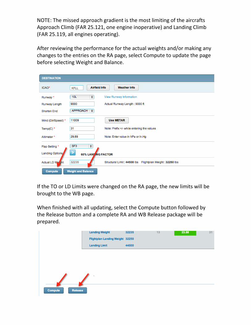
NOTE: The missed approach gradient is the most limiting of the aircrafts Approach Climb (FAR 25.121, one engine inoperative) and Landing Climb (FAR 25.119, all engines operating). After reviewing the performance for the actual weights and/or making any changes to the entries on the RA page, select Compute to update the page before selecting Weight and Balance.
If the TO or LD Limits were changed on the RA page, the new limits will be brought to the WB page. When finished with all updating, select the Compute button followed by the Release button and a complete RA and WB Release package will be prepared.

Complete the Load Manifest form as required and select the Release button on the pop-over window.
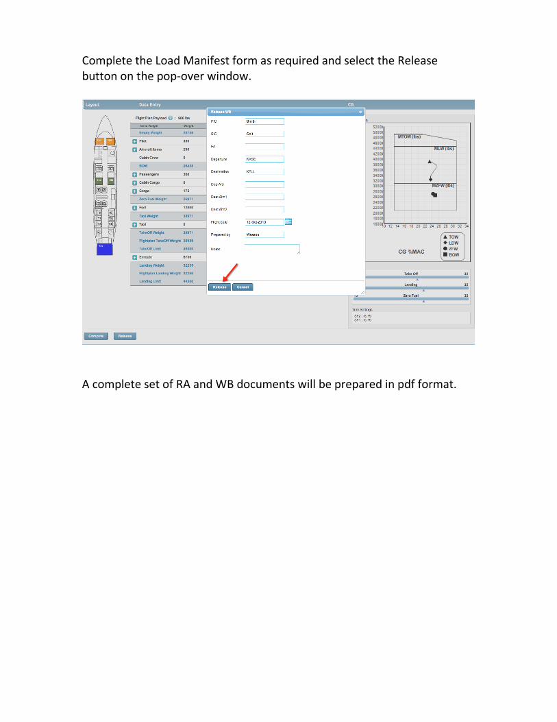
Complete the Load Manifest form as required and select the Release button on the pop-over window.
A complete set of RA and WB documents will be prepared in pdf format.

A Load Manifest:

All pages are watermarked with the aircraft’s registration number and date.: Takeoff
Engine Out Procedures – as required
Reduced Thrust – when applicable

Emergency Return – when selected
Landing


![Weight and Balance[1]](https://static.fdocuments.in/doc/165x107/577d358f1a28ab3a6b90c9fc/weight-and-balance1.jpg)


