WEDLP Edition 10 - University of Misan · PRIMARY CEMENTATION Primary cementing covers all...
31
W W E E D D L L P P E E d d i i t t i i o o n n 1 1 0 0 SECTION 6 PART 2 C C E E M M E E N N T T S S
Transcript of WEDLP Edition 10 - University of Misan · PRIMARY CEMENTATION Primary cementing covers all...
WWEEDDLLPP EEddiittiioonn 1100
SSEECCTTIIOONN 66 PPAARRTT 22
CCEEMMEENNTTSS

W181 Preparation for the Wellsite
Cementing
2
CCoonntteennttss Resumé 3
Topic 2.1 – Introduction 4
Topic 2.2 – Cement: The Product 6 2.2.1 The Choice of Cement 6 2.2.2 Cement Manufacture 6 2.2.3 Cement Chemistry Abbreviations 6 2.2.4 Cement Composition 7 2.2.5 Cement Grades 8
Topic 2.3 – Cement Hydration 10 2.3.1 Single Phase Hydration 10 2.3.2 Compound System Hydration 10 2.3.3 The Hydration Process & Heat of Reaction 11 2.3.4 Flash Set (or Quick Set) 12 2.3.5 False Set 12 2.3.6 Water/Cement Ratio 12
Topic 2.4 – Cement Types and Additives 13 2.4.1 Density Control 13 2.4.2 Dispersants or Friction Reducers 14 2.4.3 Accelerators 15 2.4.4 Retarders 16 2.4.5 Fluid Loss Control 17 2.4.6 Lost Circulation Materials 19 2.4.7 Speciality Additives 19 2.4.8 Additives in Practice 21 2.4.9 Special Purpose Cements 22
Topic 2.5 – Gas Well Cementing 24 2.5.1 Mechanisms of Migration 24 2.5.2 Solutions 26
Topic 2.6 – Cement Testing 28 2.6.1 Basic Requirements 28 2.6.2 Slurry Design 28 2.6.3 Rheology 30
Topic 2.7 – Cement Placement 31

W181 Preparation for the Wellsite
Cementing
3
OBJECTIVES After studying this Part, consulting other relevant documents and, if necessary, discussions with your mentor, you will be able to:
• List the main technical challenges (chemistry specific) for well engineering cementing. • List the primary influencing factors on cement performance. • List the main cement additives and their effects. • Describe the process for formulating, testing, preparing, placing and monitoring a cement
slurry. • List the key elements in assessing performance and economics. • Identify the main HSE aspects of cementing.
RREESSUUMMÉÉ An introduction explains why cement plays a central role in well engineering. This Part then presents sufficient information about the physical properties of cement, and the reactions involved in the setting process, including the effect of additives, for the Well Engineer to have a basic understanding of the type of slurry required for specific circumstances and what happens in the well as the cement sets. The subject of gas migration through a cemented annulus is covered, with a description of the cement chemistry methods that have been used to tackle the problem. The laboratory testing of cement slurries is described. The final Topic touches on how the slurry design affects the mechanical process of putting the cement slurry in place in the well, and describes the role of the "spacer".

W181 Preparation for the Wellsite
Cementing
4
TTOOPPIICC 22..11 –– IINNTTRROODDUUCCTTIIOONN GENERAL
Well cementing in its simplest form can be described as the placement of a material that sets to form a solid mass which has supporting and sealing properties. Annually the Group, excluding North America and Canada, spends approximately $600 million on drilling and workover related activities. Figure 6.2.1 shows a generalised distribution of this expenditure. In 1994 some $140 million was spent on drilling fluids and cementing; with about 12% being spent on cement and cementing additives. The actual expenditure varies amongst Operating Units but averages some 3-6% of the overall drilling budget. However this seemingly small portion plays a vital role in well integrity. A poor cementation can significantly impact on subsequent well performance and return on investment. In comparison to the initial expenditure, a poor cement job can result in very high remedial costs. For example, failure to achieve good zonal isolation in primary cementing (the initial cementing of casing) costs the group millions of dollars each year in well repairs and lost production.
Figure 6.2.1 : 1994 Group drilling expenditure breakdown
To achieve a successful cementation the Well Engineer must have a working knowledge of the following:
• Cement types. • Cement slurry characteristics. • Cement hydration process. • The effects of pressure and temperature on cement hydration. • The effect of additives. • Contaminants and their effects. • Cement testing procedures and terminology. • Wellbore fluid displacement and mud cake removal. • Primary and secondary cementing techniques. • Evaluation procedures.
REASONS FOR CEMENTING Cementing jobs are carried out in oil wells for a number of reasons, including:
• Well tubular support:
To provide support for casing/liner strings to prevent movement. • Well bore/tubular collapse: To resist plastic/brittle deformation of the surrounding formation which may impact upon
well tubulars and cause their collapse. • Zonal isolation:

W181 Preparation for the Wellsite
Cementing
5
To provide a pressure (to Gas) tight seal between different zones (formation-formation or formation-surface). Includes sealing perforations to control water production or prior to a workover.
• Corrosion protection: To isolate metal tubulars from corrosive gases and liquids contained in the formations. • Kick-off plugs: To fill the hole with a material that is harder than the surrounding formation to encourage
the drill string to deviate from the original borehole trajectory. • Lost circulation cures: A material that will permanently seal leakage paths into the formation. • Well abandonment: To isolate all open hole sections from the surface.
PRIMARY CEMENTATION Primary cementing covers all operations to fix a casing and/or liner string in a newly drilled wellbore. The cement slurry is placed in the annulus between the pipe and the wall of the open hole. In this placement the cement has to displace the annular contents, usually drilling fluid, as completely as possible to permit adequate bonding to pipe and formation as well as developing its sealing properties.
SECONDARY CEMENTATION
Secondary cementation covers all applications other than primary cementing; including the repair of an unsuccessful primary cementation. Cement is either injected under pressure (squeeze job) or placed into the required position (plug job).
A SUCCESSFUL CEMENTATION
The key to successful primary and secondary cementations is proper ‘up-front engineering’ in the design stage and close, involved and experienced supervision of the execution phase. Factors that can positively affect the success of a cementation include:
• Adequate and timely testing of slurries using field sampled materials and water. • Proper blending of cement and additives. • High energy, recirculating mixing. • The use of centralises and/or scratchers. • Reciprocating or rotation of the casing/liner string during displacement. • Proper drilling fluid properties. • Adequate displacement rate.
The role of the Well Engineer and the Drilling Chemist is to focus on fit-for-purpose specifications in a partnership with the Cementing Contractor who concentrates on the detailed design and execution aspects.

W181 Preparation for the Wellsite
Cementing
6
TTOOPPIICC 22..22 –– CCEEMMEENNTT:: TTHHEE PPRROODDUUCCTT 2.2.1 THE CHOICE OF CEMENT The requirement is to have a material which is pumpable but which sets and hardens after placement. Although there are a number of chemicals available, e.g. epoxy, high load polymers, elastomers, cement has some distinct advantages:
• It is a ‘Fit-For Purpose’ Hydraulic Material that hardens to a sufficient compressive strength and low permeability for most well applications.
• There is an abundant supply readily available world-wide. • Price, being a commodity product cement is cheaper than any alternative material. • Experience in manufacturing, preparation and placement technology is mature. • Additives are available to modify its performance to most specifications.
As with every material, cement also has its limitations: • Cement has a variable composition and therefore can have a variable performance. • It shrinks during setting which can compromise it bonding properties. • It is susceptible to chemical contamination which affect short and long term performance. • The hydration process is susceptible to the physical conditions present in the well. • It is expensive to manufacture to individual specifications.
2.2.2 CEMENT MANUFACTURE All classes of cement are prepared in essentially the same way and made up of the same ingredients, only in different proportions. The basic process is:
• The cement is prepared by kiln-burning limestone with clay to form ‘clinker’. - Average kiln temperature is 1,300°C to 1,500°C. - Iron and alumina may be added if the clay source is deficient in these ions.
• Cooling of the clinker is done in two stages: slow cooling to 1,250°C followed by rapid cooling at 18-20°C/min - Cooling too slowly results in a cement which is not hydraulically active. - Cooling too fast results in a cement with poor long term strength.
• Gypsum is dry blended during grinding of the Clinker. - This is to prevent ‘Flash’ Setting. - The mill must be cool at this stage to prevent the gypsum dehydrating to Anhydrite as
this can result in ‘False’ setting. • Storage in airtight silos.
- Cement is hygroscopic and sensitive to moisture and CO2. - Storage in hot regions can result in dehydration of Gypsum to Anhydrite.
2.2.3 CEMENT CHEMISTRY ABBREVIATIONS A set of abbreviations is used when discussing cement chemistry, composition and properties.
Composition Elements
C = CaO F = Fe2O3 N = Na2O P = P2O5
A = Al2O3 f = FeO M = MgO K = K2O
S = SiO2 H = H2O L = Li2O T = TiO2

W181 Preparation for the Wellsite
Cementing
7
Hydration Compounds C2S = 2CaO.SiO2 C3A = 3CaO.Al2O3
C3S = 3CaO.SiO2 C4AF = 4CaO.Al2O3.Fe2O3
Sulphate Resistance
Sulphates can react with cement decreasing its long term strength and increasing porosity. MSR = Moderate sulphate resistance HSR = High sulphate resistance.
Bearden Units of Consistency (Bc.)
No direct correlation to other rheology measurements. Used to evaluate slurry pumpability during displacement and initial setting.
Concentration BWOC = By Weight Of Cement BWOW = By Weight Of Water.
2.2.4 CEMENT COMPOSITION Portland cement contains four basic components, each contributing in different ways to the properties of a slurry and/or the set cement. Small changes in the concentration may significantly affect the setting behaviour of a cement. Individual testing of all cement batches, with field sampled material, is a prerequisite to avoid unexpected setting characteristics.
Table 6.2.1 : The main consituents of Portland cement
ID Mineral % mass Characteristics
C3A Tri-Calcium Aluminate <3-15
Reaction between Calcium and Aluminum Oxide. Hydrates and sets rapidly: important for early strength development. It is attacked by sulphate ions causing deterioration of the cement structure. HSR cements contain <3% C3A.
C3S Tri-Calcium Silicate 40-65
Reaction between Calcium and Silicon Oxide. It is the major component of oilwell cements. It contributes to all stages of strength development.
C2S Di-Calcium silicate 16-54
Reaction between Calcium and Silicon Oxide. Hydrates slowly: no influence on initial cement setting, contributes to the final strength development only.
C4AF Tetra-Calcium Alumino-Ferrite 8-12
Reaction of Calcium, Aluminum and Iron Oxides. It hardly affects the cement hydration process but forms an interstitial structure in the clinker grain.

W181 Preparation for the Wellsite
Cementing
8
It is possible to change the properties of the cement by changing the ratio of the basic components, the process temperature, the rate of cooling or by adjusting the grinding of the cement clinker to yield coarser or finer grains. This is done as follows:
• High Early Strength (Most Oilfield Cements). - Increasing the C3S Content. - Grinding Finer.
• Better Retardation (HPHT Applications). - Reducing C3S and C3A Content. - Grinding Coarser.
• Low Heat of Hydration (Permafrost Applications) - Reducing C3S and C3A Content.
• Resistance to Sulphate Attack (Most Oilfield Cements). - Reducing the C3A Content.
2.2.5 CEMENT GRADES The American Petroleum Institute (API) has designated eight classes of oil well cement (reference API Standards 10 “Specification for Oil-Well Cements and Cement Additives”). These are shown in Table 6.2.2. Most oilfield cements are API “Portland” cement Class G. It is primarily intended for use from surface to 2,500m; covering the range of typical temperatures and pressures encountered. Typical properties of API Class G Portland cement are (note that a “sack” has been made equal
Figure 6.2.2 : Typical Class G cement setting characteristics
Table 6.2.2 : API oil-well cement classes
API class PURPOSE
Slurry Density Kg/m3
Mixing Water Kg/Kg
Slurry Yield Kg/Kg
A 0-2000m General purpose. Low/Medium Sulphate Resistance 1,875 0.461 0.779
B 0-2000m General purpose. High Sulphate Resistance 1,875 04.61 0.779
C 0-2000m High Early Strength 1,780 0.555 0.874
D 2000-3000m Retarded cement, temperature range 77-110°C 1,970 0.384 0.702
E 3000-5000m Retarded cement, temperature range 110-145°C 1,970 0.384 0.702
F 3000-5000m Retarded cement, temperature range 145-160°C 1,970 0.384 0.702
G 0-2500m General purpose up to 195 °C Available MSR and HSR 1,890 0.447 0.765
H 0-2500m General purpose up to 195 °C Available MSR and HSR: coarser grind 1,920 0.422 0.741

W181 Preparation for the Wellsite
Cementing
9
to one cubic foot): Specific Gravity 3·15 Bulk Volume 1·47 kg/l 94 lbm/ft3 Water Requirement 18·9 l/sack 5.00 gal/sack Slurry Weight 1·89 kg/l 15.8 lbm/gal Slurry Volume 32·56 l/sack 1.15 ft3/sack
Class H is identical in composition but has a coarser grind. During the manufacture of classes G and H no additives can be included. Only calcium sulphate (gypsum) and water may be added to the clinker. Glycols and acetates which improve grinding efficiency cannot be used; these interfere with other cement slurry additive performance. Both classes G and H are available as MSR or HSR. API classes D, E and F contain a retarding additive and therefore will exhibit adequate thickening time when used in the correct temperature range. Be aware that these additives may be incompatible with other desired additives (e.g. for fluid loss control). The general purpose class G and H cements are preferred as the properties can be adjusted within wide margins to suit a range of applications. Oil-well cement usually represents some 3% - 4% of the total capacity of a manufacturer. Coupled with the much more stringent specification and quality criteria, it usually commands a higher price. It is recommended to obtain oil-well cement from a reputable manufacturer who has been API certified; though this is not an absolute guarantee of consistent quality.

W181 Preparation for the Wellsite
Cementing
10
TTOOPPIICC 22..33 –– CCEEMMEENNTT HHYYDDRRAATTIIOONN The exact mechanisms in the hydration of cement are not fully understood. A general outline, however, can be given .
2.3.1 SINGLE PHASE HYDRATION
SILICATE PHASES (C2S & C3S).
• Form C.S.H. (C3S2H3) ‘Gel’; ±70% of fully hydrated Portland cement. Ultimately the principle binder of hardened cement.
• C3S is responsible for the beginning of set and early strength development. • C2S is responsible for the final strength. • There are five distinct stages in the setting process of the silicate phase:
Stage Name Time Chemical Action Heat Pre-induction Hydration Few Minutes Rapid C2S Hydration & C.S.H Gel Formation Exothermic Induction Slurry Few Hours Slow C.S.H. Gel Formation & Grain Hydration Neutral Acceleration Gelling Minutes Lime Drop-out & C.S.H. Infilling Water Filled Spaces. Exothermic Deceleration Setting Days C.S.H. Gel Hydrate Intergrowth. Neutral Diffusion Hardening Indefinite C3S Hydration. Neutral
ALUMINATE PHASES (C3A & C4AF). • Rapidly hydrate. • Predominantly influential on rheology and early strength development. • Rate controlled by the addition of gypsum which forms the needle like mineral ‘Ettringite’
which slows down the hydration rate.
2.3.2 COMPOUND SYSTEM HYDRATION However the actual hydration process of Portland cement is a sequence of overlapping chemical reactions leading to continuous thickening and hardening. The C2S model is generally used to represent this process; however the phases influence each other and should be considered.
• The hydration of C3A is modified by the presence of hydrating C3S. • The clinker material is not pure and trace elements can catalyse reactions. • The hydration rate and nature, stability and morphology of the hydration products are
strongly affected by temperature. Elevated temperature (>40°C) accelerates initial hydration; but may decrease the ultimate hydration and compressive strength.
• Particle size distribution affects the hydration rate, initial setting time and final strength. • Sulphates can react with the set cement and reduce strength and increase porosity.

W181 Preparation for the Wellsite
Cementing
11
2.3.3 THE HYDRATION PROCESS & HEAT OF REACTION When cement is mixed with water two distinct peaks of heat liberation can be distinguished. Each of these peaks results from an important phase in the hydration process. This feature is useful in laboratory studies to identify the onset and completion of cement setting.
The first peak occurs almost immediately after the mixing, in the Pre-induction stage. It is caused by an exothermic reaction between C3A, gypsum and water. The surface of the C3A grains is partly hydrated and dissolving gypsum moves towards this hydration layer. A thin C.S.H. gel layer forms at the surface of the C3A and C4AF grains. The slurry then enters an apparent ‘dormant’ period, the Induction stage. During this period the slurry remains liquid and it appears that all reactions have stopped.
However the reaction within the hydration layer continues and after a given time, the hydration layer bursts open – the Acceleration stage. Fibrils of recrystallising material grow rapidly from the cement grains. This recrystallisation process causes a second peak of heat liberation. The fibrils initially interfere with each other causing an increase in gel strength. Ultimately they connect and form the basic cement structure and give rise to the early strength development. The reactions now slow down – the Deceleration stage – but the cement strength continues to build up. The reactions continue on for some time, albeit very slowly – the Diffusion stage – during which the ultimate strength is developed. Initial hydration may be adversely affected if the cement has been exposed to a humid atmosphere.
Figure 6.2.3 : Cement Hydration terminology
Figure 6.2.4 : Thermogram of setting Portland cement
A sound mixing/shearing of the initial slurry will give rise to a more regular initial hydration and therefore to a better final cement structure. The length of the dormant period and therefore the final setting time of the cement is determined by the slurry temperature and can be adjusted by a number of accelerating or retarding additives.

W181 Preparation for the Wellsite
Cementing
12
2.3.4 FLASH SET (OR QUICK SET) When Portland cement clinker, without sufficient gypsum, is hydrated the C3A rapidly reacts, the temperature increases and an irreversible ‘Stiffening’ occurs.
2.3.5 FALSE SET During grinding, natural calcium sulphate in the Clinker is dehydrated to Anhydrite which has a higher solubility. Consequently, in the slurry secondary Gypsum precipitation can occur. This gives rise to strong thixotropy, or very high gel strengths. This can appear, due to a surface pump pressure increase, as a flash set. However this gel is reversible upon strong agitation.
2.3.6 WATER/CEMENT RATIO The minimum required amount of mix water for cement hydration is some 0·150m3/1,000kg of cement. This, however, leads to a very viscous, unpumpable, slurry. In oil well cementing ratios between 0·38m3/1,000kg and 0·5m3/1,000kg are routinely used. Optimum water/cement ratios are defined for the various types of cement (reference Contractor Cementing tables).

W181 Preparation for the Wellsite
Cementing
13
TTOOPPIICC 22..44 –– CCEEMMEENNTT TTYYPPEESS AANNDD AADDDDIITTIIVVEESS The properties of regular Portland cement don’t always conform to the job at hand.
• Temperatures from Ambient to >350°C. • Pressure from Atmospheric to > 200 MPa. • Pumping Times from Minutes to Hours.
Additives are used to modify cement properties and can be categorised as: • Density Control. • Dispersants or Friction Reducers. • Accelerators: increase hydration rate, decrease pumping time. • Retarders: decrease hydration rate, increase pumping time. • Fluid Loss Control: reduce aqueous phase losses. • Lost Circulation Control. • Speciality Additives. • Speciality Application.
2.4.1 DENSITY CONTROL During placement well control must be maintained. The cement density may need to be adjusted to ensure that the bottom hole pressure remains within finite limits. A cement slurry density can be increased with heavy-weight additives (such as barytes or hematite) or saline mix water or by using less mix water (though this may have other detrimental effects).
A cement slurry density can be reduced by ‘extending’. This means adding a material to reduce the grain density and at the same time enabling a higher water/cement ratio to be used. The filler material may be inert, i.e. does not have hydraulic properties or it may contribute, on account of its siliceous nature, to
the setting and strength characteristics of the cement. Addition of bentonite or spherelite will lead to a reduction in compressive strength of the final cement. This effect is less pronounced with the use of pozzolan which reacts with free lime to form a cement material.
Table 6.2.3 : Components for light-weight cement slurries
Inert fillers Hydraulic fillers Diatomaceous earth Pozzolan volcanic ash
Perlite Fly ash e.g. from power stations
Glass/Ceramic spheres Blast furnace slag
Gilsonite Sodium (meta) silicate
Nitrogen
Figure 6.2.5 : Density range for various cements & additives

W181 Preparation for the Wellsite
Cementing
14
POZZOLANIC CEMENTS Pozzolan was originally a volcanic ash named after the place in Italy where it is found in large quantities. The term is now used for a group of materials that react with lime to form cement like compounds; such as blast furnace ‘fly-ash’. Pozzolans are mostly blended in a 1:1 ratio with API Class B oil-well cement. They have been extensively used in various cementing industries. Pozzolan cement blends have a grain density of 2,820 kg/m3 and a bulk density of 1,185 kg/m3. Pozzolan cement slurries have gradients in the range 15·5 to 16·0 kPa/m (13·2 to 13·6 ppg) but can be made into stable slurries in the range 14·5 to 17·0 kPa/m (12·3 to 14·7 ppg), using additives. An additional advantage of Pozzolans is a reduction in natural cement strength retrogression. When Portland cement hydrates it releases some 20%mass lime. This contributes nothing to the strength of the cement, but being soluble it eventually leads to a weakening of the matrix. Pozzolan combines with the lime increasing the strength and reducing the permeability of the cement. The main attraction of natural Pozzolan is its consistent quality. The quality of fly-ash can vary significantly between sources. It also differs from volcanic ash in that it also contains iron oxides (Si, Al and Fe). The use of fly-ash should be accompanied by quality control testing to achieve satisfactory results. Fly-ash in Portland cement is usually blended in a 50/50 by volume ratio in admixture with 2-4% bwoc of bentonite to improve stability and reduce ‘free water’.
FLY-ASH CEMENTS
Fly ash and lime can be prepared and need no addition of Portland cement. Their reaction is slower and the mixture is therefore suited to high temperatures.
SLAG MIX
‘Pozzolan’ or ‘Fly Ash’ is the cement material used in the preparation of ‘Slag Mix’ or ‘S-Mix’ cements. In this system drilling fluid is used as the mix water. Because of the highly variable nature of drilling fluids extensive testing is usually required to ensure a good quality job. It is essential that the drilling fluid sampled for testing is not used again.
2.4.2 DISPERSANTS OR FRICTION REDUCERS For maximum displacement efficiency (i.e. mud removal) the cement should be as thin as possible and be displaced at maximum velocity. Well cement slurries are highly concentrated suspensions of solids; up to 70% by volume. There is an electrostatic interaction between the C.S.H. layers around the grains; similar to the interaction with bentonite particles. A dispersant aims to reduce this viscosity effect in the cement slurry, thereby promoting turbulent flow at lower pump rates. The need for a well dispersed low viscous cement slurry becomes more and more critical with deeper, slimmer, hotter wells. Organic acids, in particular polysulphonates, are the most common dispersants. Modified polysaccharide polymers are also effective dispersants. See Table 6.2.4. Dispersants also retard hydration and reduce thixotropic properties. The combination of a dispersant with a fluid loss reduction additive exhibits strong synergy. Excessive use of dispersants can lead to settling of the cement particles causing segregation and non-uniform slurry densities This is particularly important with batch mixed job that are not adequately agitated before pumping.

W181 Preparation for the Wellsite Cementing
15
2.4.3 ACCELERATORS Accelerators are materials that shorten the thickening time of the cement slurry and accelerate strength development in situations where low temperatures would lead to excessive waiting on cement times. They are often used to offset the hydration delaying effect of other additives. They are usually inorganic salts. There is an efficiency series of: Ca++ > Mg++ > Li+ > Na+ > H2O; OH- > Cl- > Br- > NO3
- > SO4-- = H2O
CaCl2 is the most cost effective accelerator. In dosages of 0 to 5% BWOW (2 - 4% BWOC) it will accelerate the setting of a slurry by up to 30%. Concentrations of CaCl2 higher over 5% are not recommended as the reaction becomes very unpredictable.
Table 6.2.4 : Dispersants
Application� Product BJ Services Dowell Halliburton NOWSCO Western Co.
Powder CD-31, CD-32
D65 D121
CFR-2 CFR-3 T-10 TF-4
TF Plus 500 General application� Liquid CD-31L,
CD-32L D80 D145 CFR-2L, CFR-3L T-10L TF-4L
Powder/ granules D45
D65A FE-2 CFR-3 T-11 XR-2
Dispersant for salt-saturated slurries�
Liquid D80A, D604AM CFR-3L
Powder CD-32 CFR-2
Dispersant with non-settling or anti-settling characteristics� Liquid CD-32L D604M CFR-2L
Table 6.2.5 : Accelerators
Material� Product� BJ Services� Dowell� Halliburton� NOWSCO� Western Co.�
Sodium chloride (common salt) Granular A-5
NaCl D44 Salt NaCl NaCl
Solid A-7 CaCl2
S1 CaCl2 CaCl2 CaCl2 Calcium Chloride�
Liquid A-7L, CaCl2-L D77 CaCl2 Liquid CaCl2-L
Powder or beads
A-2, Sodium Metasilicate, Diacel A
D79 Diacel A
Econolite, Diacel A EXC Thrifty-lite,
Diacel A Sodium Silicate�
Liquid A-3L Sodium Silicate D75 Liquid Econolite EXC-L WE-1L
Calcium sulphate (hemihydrate or gypsum)
A-10 or Gypsum D53 Cal-Seal EA-2 Gyp-Cem Thixad
Potassium Chloride A-9 or KCl M117 KCl KCl KCl Ammonium Chloride NH4Cl
CaCl2 dissolution is an exothermic reaction. Therefore to avoid any side effects caused by a high mix water temperature it should be added to the mix water several hours in advance. NaCl is also a commonly used accelerator. Up to 10% bwow it will accelerate the setting by some 20 %. Between 10 and 18% it is neutral. Over 18% it is a retarder. Magnesium salts are also very powerful accelerators. Aluminium sulphate is also a very effective accelerator. However its thixotropic effect makes it less attractive for most applications as it will adversely affect displacement and give unacceptably high ECDs.

W181 Preparation for the Wellsite Cementing
16
The actions by which accelerators work are very complex and not fully understood. Predominantly they accelerate the hydration of C3S. CaCl2 changes the C.S.H. gel structure to make it more permeable and allow more diffusion of water to the underlying clinker. Chloride ions diffused into the C.S.H. gel cause excessive internal pressures resulting in an earlier rupturing of the membrane. CaCl2 Increases the rate of heat generation during the first few hours which accelerates the chemical reactions.
2.4.4 RETARDERS These products are applied to achieve the opposite effect of accelerators, i.e. increasing the thickening time, at the temperature and pressure, to allow the slurry to be placed before initial set. Most retarders are organic acids, salts or polymers. The most common are Na- and Ca-lignosulphonic acids. The active components are the saccharide carbohydrates and aldonic acids which are naturally present in the raw material. Refined lignosulphonate, as used in drilling fluids, are deficient in these compounds and therefore should not be used. Lignosulphonates are most effective in the range of 0·1 - 1·5% bwoc. Cellulose derivatives such as CMHEC are also effective retarders; as are organophosphates, such alkylene phosphonic acid and NaCl at concentrations >18% BWOW. Most retarders are characterised by an exponential response in the thickening time of the cement slurry, i.e. at low dosage rates the effect is rather small but it increases exponentially with further chemical addition (See Figure 6.2.7). Therefore they should only be used over a certain concentration range. The retarding effect is temperature dependent and most commercial products can be used only in a given temperature range. A common, beneficial, side-effect of a retarder is the reduction of slurry viscosity and yield point due to its dispersive action.
Figure 6.2.6 : Action of accelerators and retarders on cement hydration
Figure 6.2.7 : Impact of retarder concentrations

W181 Preparation for the Wellsite Cementing
17
Table 6.2.6 : Retarders
Application� Product� BJ Services� Dowell� Halliburton� NOWSCO� Western
Co.�
Powder� R-1� D13� HR-4 HR-7� R-6� �
Low temperature�� Liquid� � D81� HR-4L
HR-7L� R-6L� WR-2L�
Powder R-3 D800 HR-5 WR-15 Mid-temperature range� Liquid R-21
R-21L D801 HR-6L R-40L
Liquid D110 Moderate to high temp.� Powder R-6 or
Diacel LWL D8 Diacel LWL Diacel LWL Diacel LWL
Powder R-8 D28 HR-12 HR-15 HR-20
R-55 R-57 WR-6, WR-7
High temperature�
Liquid R-23L D150 HR-12L, HR-13L R-55L WR-6L
Auxiliary retarder, synergistic to lignosulphonates
Powder R-9, Sodium Borate
D93 D121
H-25, Component R R-35 WR-7
Powder HR-25, SCR-100
Synthetic retarder� Liquid HR-25L,
SCR-100L
Powder SCR-100 High temp. differential over cement column� Liquid D110 SCR-100L Retarder for microfine cements Liquid MMCR
Thixotropic cement retarder Powder R-18 D74 WR-10
Powder R-7 D13 HR-4, Sodium Citrate
R-7 R-15 XR-2 Permafrost cement
retarder� Liquid D81 HR-4L WR-2L
2.4.5 FLUID LOSS CONTROL Neat cement slurries exhibit a very high, essentially uncontrolled, fluid loss against a permeable media. For most cementations some measure of fluid loss control is highly desirable to prevent excessive slurry dehydration. An API fluid loss of 150 to 300 cm3 (Spec. 10A) is recommended to provide adequate control for primary cementations. Most of the fluid loss reducers in use are either a cellulose derivative, a polymer or a filter cake building solid. These additives will generally act as retarders. They also tend to increase slurry consistency, which is usually countered by adding some dispersant. Like retarders, fluid loss control additives exhibit a temperature dependent action within a specific envelope.

W181 Preparation for the Wellsite
Cementing
18
Table 6.2.7 : Fluid loss control additives
Application� Product�
BJ Services Dowell Halliburton NOWSCO Western
Co.
Powder
FL-62 D127 D146 D156
LAP-1,LA-2. Halad:
-322, --344 -413�
D-19 D-23, D-24 NFL-2�
CF-18 CF-19, CF-20LT, CF-22� Low temperature �
Liquid� � � Halad:
-322L, -344FS -361, -413L�
LD-18 LD-24�
CF-18L, CF-20L, CF-22L
Powder
FL-25 FL-33 FL-52 FL-62, Diacel LWL
D8, D59 D60, D65A D73, D73.1 D143, D158, D159, D603, Diacel LWL
LAP-1, Flobloc 210 Halad:
-14, -19 -322, -22A –344 -413
-100A Diacel LWL�
D-24 D-28 NFL-1, NFL-2, NFL-3, Diacel LWL
WL-1P CF-1, CF-2 CF-14, CF-15 CF-18, CF-19 CF-20, CF-22, Diacel LWL
General application�
Liquid
FL-33L D80A, D604AM
Halad: -9L, -14FS
-322L, -322FS -10L, -22AL
-413L, -316A�
D-28L LD-18 LD-24�
WL-1L, CF-20L, CF-18L, CF-22L�
Latex: Styrene/butadiene copolymer or similar Liquid BA-86L D600
D134 Latex 2000 Gas Lok
Powder LAP-1, Flobloc 210
WL-1P Latex: Acrylic�
Liquid LA-2 WL-1L
Powder FL-52 D112
D156 D-23
D-24 NFL-2
CF-20 Fluid loss control in highly extended or low density slurries �
Liquid D159 LD-24 CF-20L Stabiliser for Latex in the presence of salt or high temperatures
Liquid Available as needed
D135 434B 434C
Gas Lok S
Stabiliser for Latex in low density slurries Liquid D138 434B
434C TF-4L
Fluid loss aid Powder D136 D121
TF Plus 500
Hydroxyethylcellulose derivatives (such as CMHEC) are common fluid loss reducers. The HEC polymer molecules tie up the water and prevent it from freely leaking off. This loss of free water results in a slurry viscosity increase. Other types of fluid loss reducers, such as Diacel LWL, build up a filter cake. It should be emphasised that this type of products will only work if the slurry is sufficiently dispersed to provide the small particles required for a good filter cake.
FREE WATER AND PARTICLE SETTLING Non-homogeneous cement columns are unacceptable, particularly when the wellbore is highly deviated or horizontal. Ultimate cement sheath integrity and strength may be severely compromised. Anti-settling agents are used to provide (or restore with the use of dispersants) sufficient viscosity to maintain slurry consistency. Bentonite and HEC derivatives are most commonly used to restore this viscosity. For deviated and horizontal wells it is important to test this phenomena at the actual well angle.

W181 Preparation for the Wellsite
Cementing
19
2.4.6 LOST CIRCULATION MATERIALS Lost circulation is a potential problem when drilling through permeable, well fractured, faulted or cavernous formations. To restore circulation, or reduce the chance of creating losses during cementation, lost circulation materials may be added to the cement.
Table 6.2.8 : Lost Circulation materials
Material� Product� BJ Services� Dowell� Halliburton
� NOWSCO� Western Co�
Thixotropic cement formulations� Slurries
Sure Fill Sure Plug Thixofill Thixofume Gypsum Cement
RFC D53 Cement
Thix-Set Thix-Set 31 Thixlite 373 Cal-Seal Cement VersaSet
Thix-Mix Thermal Thix-Mix Expandomix, RapidgelSPC Rapid Set
Thixoment Thriftyment Thixolite Quick-Set Cement
Foamed cement Slurries Foamed cement
Foamed cement
Foamed cement
Foamed cement
Foamed cement
Non-aqueous slurries May or may not contain
cements Slurries
DO/Cement Visqueeze II DO/Bentonite
PolymerPlug SOS
BDO BCDO DOC
Diesel Gel Diesel Cement
DO/Bentonite
Non-aqueous slurries Slurries MOC-1
Reactive washes Liquid mixtures
Flow Guard L Stop Block SAF III
Zonelock Permablock
SuperFlush Thixseal Aquafix-1 Temposeal Surebond
Sand Sand Sand Sand Sand Sand Mica Mica Mica Mica
Cellophane flake Celloflake D29 Flocele Celloflake Cello-Seal Gilsonite Gilsonite D24 Gilsonite Gilsonite Gilsonite
Ground coal Kol Seal D42 NLC-1 Hi-Seal 2 Walnut plugs or similar Nut Plug Tuf Plug Tuf Plug
Perlite Perlite D72 Perlite Perlite Fibers of Nylon,
cellulose polypropylene, or similar
Tuf Additive
No. 2 Hi-Seal 3
Wood chips Wood chips Wood chips Wood chips Polyester, ground
thermoplastic rubber, etc.
Flex Seal D130 Granulite
TR 1/4 Hi-Seal-2,-3
Mud-Save
Kwik Seal Kwik Seal Kwik Seal
2.4.7 SPECIALITY ADDITIVES
EXPANDING AND BOND IMPROVEMENT Ordinary Portland cement shrinks about 4% upon setting. This can reduce bottom hole pressure below the static slurry and compromise the cement bond. These agents target reducing shrinkage.
Chemical or crystal growth expanders Calcium sulphate hemi-hydrate and calcined magnesium oxides are the most prominent compounds. They produce their expanding effect well after the cement has set.
W181 Preparation for the Wellsite
Cementing
20
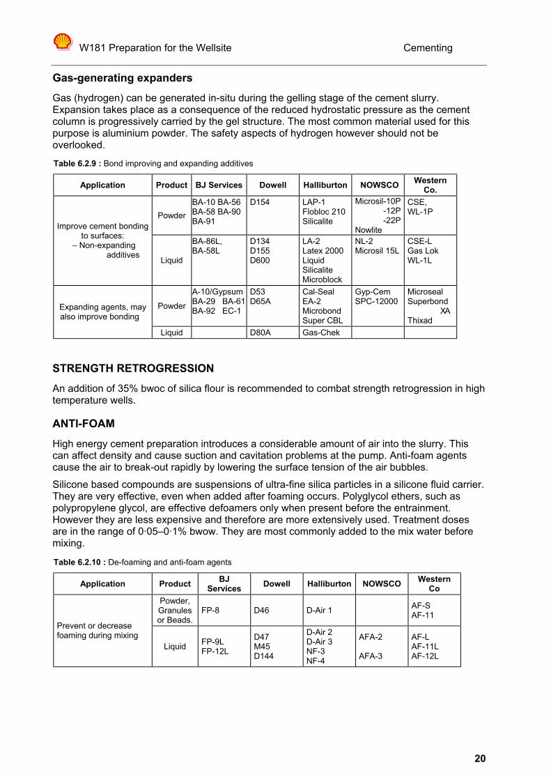
Gas-generating expanders Gas (hydrogen) can be generated in-situ during the gelling stage of the cement slurry. Expansion takes place as a consequence of the reduced hydrostatic pressure as the cement column is progressively carried by the gel structure. The most common material used for this purpose is aluminium powder. The safety aspects of hydrogen however should not be overlooked.
STRENGTH RETROGRESSION An addition of 35% bwoc of silica flour is recommended to combat strength retrogression in high temperature wells.
ANTI-FOAM
High energy cement preparation introduces a considerable amount of air into the slurry. This can affect density and cause suction and cavitation problems at the pump. Anti-foam agents cause the air to break-out rapidly by lowering the surface tension of the air bubbles. Silicone based compounds are suspensions of ultra-fine silica particles in a silicone fluid carrier. They are very effective, even when added after foaming occurs. Polyglycol ethers, such as polypropylene glycol, are effective defoamers only when present before the entrainment. However they are less expensive and therefore are more extensively used. Treatment doses are in the range of 0·05–0·1% bwow. They are most commonly added to the mix water before mixing.
Table 6.2.9 : Bond improving and expanding additives
Application Product BJ Services Dowell Halliburton NOWSCO Western Co.
Powder BA-10 BA-56 BA-58 BA-90 BA-91
D154 LAP-1 Flobloc 210Silicalite
Microsil-10P -12P -22P
Nowlite
CSE, WL-1P
Improve cement bonding to surfaces:
– Non-expanding additives� Liquid
BA-86L, BA-58L
D134 D155 D600
LA-2 Latex 2000 Liquid Silicalite Microblock
NL-2 Microsil 15L
CSE-L Gas Lok WL-1L
Powder
A-10/Gypsum BA-29 BA-61 BA-92 EC-1
D53 D65A
Cal-Seal EA-2 Microbond Super CBL
Gyp-Cem SPC-12000
Microseal Superbond XA Thixad
Expanding agents, may also improve bonding�
Liquid D80A Gas-Chek
Table 6.2.10 : De-foaming and anti-foam agents
Application Product BJ Services Dowell Halliburton NOWSCO Western
Co Powder, Granules or Beads.
FP-8 D46 D-Air 1 AF-S AF-11
Prevent or decrease foaming during mixing�
Liquid FP-9L FP-12L
D47 M45 D144
D-Air 2 D-Air 3 NF-3 NF-4
AFA-2 AFA-3
AF-L AF-11L AF-12L

W181 Preparation for the Wellsite
Cementing
21
2.4.8 ADDITIVES IN PRACTICE
SECONDARY EFFECTS Some additives have secondary effects on other cement properties. For example using CMHEC as a fluid loss additive retards hydration and increases slurry viscosity
INFLUENCE OF PHYSICAL CONDITIONS ON ADDITIVE PERFORMANCE
As with all additives, the physical conditions of storage, mixing and placement can have a significant impact of their performance.
Figure 6.2.8 : Effect of various additive types on hydration time
Figure 6.2.9 : Effect of physical condition on retarder performance
ADDITIVE QUALITY CONTROL
Additive effectiveness can be control by many factors: • Cement property variance. • Physical conditions. • Mix water chemistry and contaminants • Preparation and placement conditions. • Additive quality

W181 Preparation for the Wellsite
Cementing
22
• Age versus shelf life and storage conditions. • Additive interaction (+ve synergy or the opposite)
Some additives and combinations under certain conditions can give rise to a ‘Reverse Temperature Effect’. Hydration modifier performance is inversely proportional to the temperature profile over a specific temperature range. Quality testing is essential to obtain a slurry composition with requisite properties. All samples must be taken from all ingredients to be used for the cementing job on hand, including the mix water.
ADDITIVE MIXING
Dry Blending with Cement
The mixing of a relatively small quantity of a powdery product, typically 1% into a large matrix is rather problematic and can easily result in a poor, inhomogeneous distribution. This method is not recommended.
Mixing in the Mix-Water
This affords a good control over the actual rates applied and ensures a consistent treatment. Although waste is incurred because, as a contingency, most of the time the volume of mix water prepared is larger than actually needed for the job, the simplicity of the operation and the accurate dosing makes this the preferred route. It is essential to ensure that the crew only mix at the desired concentration. “Finishing the bag” with some additives (such as high performance retarders) can significantly affect slurry performance.
Mixing liquid additives ‘on the fly’
Liquid additives are fed directly into the mix water tanks of the cement unit when filling up. This avoids the waste of the mix water quantity. Accurate dosing requires a reliable, often complicated, metering system able to stand the rigours of a cementing operation. This method therefore can be recommended only for advanced and integrated operations.
2.4.9 SPECIAL PURPOSE CEMENTS
THIXOTROPIC CEMENT
In lost circulation situations a thixotropic slurry may resist losses to the formation by rapidly developing a self-supporting gel structure. This carries part of the hydrostatic pressure of the cement column thereby reducing the bottom hole pressure. Shear breaks the (fragile) gel structure making it possible to pump the slurry. Thixotropic slurries are often used for plug cementations to avoid slumping into the lighter fluid. The thixotropy is generally achieved by adding gypsum. Bentonite will also increase the thixotropy of a slurry.
FOAM CEMENT Foam cement is created by injection of air or nitrogen and a surfactant into a conventional neat slurry. It will create a light weight slurry with a gradient limit of about 8 kPa/m (6·8 ppg). It will develop a lower compressive strength than neat cement. Caution needs to be taken with well control as the slurry will have a variable hydrostatic head due to compression of the gas bubbles.

W181 Preparation for the Wellsite
Cementing
23
ULTRA FINE CEMENT Portland cement clinker is ground to a much smaller, nearly sub-micron particle size. The smaller size allows the particles to pass through pore throats. The cement forms an internal filter cake resulting in better sealing and shut-off after setting.
SURFACTANT CEMENT Surfactants are added to the slurry formulation to aid in gas influx control. However their effect remains unproven and most migration is believed to be via micro-annuli which remain unaffected. Cationic surfactants precipitate the positively charged cement particles and accelerate setting.
LATEX CEMENT Cements with >25% bwoc latex added have a higher tensile strength than ordinary cement that resisting stress cracking from subsequent temperature and pressure fluctuations.
FIBRE CEMENT
In this development from Shell, polypropylene fibres are added to a conventional slurry. The fibres increase the tensile strength of the set cement which will improve the cement sheath integrity during subsequent drilling phases. The fibres also resist fluid losses in fractured formations.
SLAG-MIX CEMENT
A blast furnace slag, together with an activator (lime or caustic soda), is mixed with a drilling fluid in conventional cementing equipment. The main advantages are less shrinkage, <1%, and waste reduction by using the drilling fluid. Extensive testing of the mix is required to achieve the desired results. Do not use the drilling fluid after sampling for testing as its composition may change thus affecting the setting characteristics.

W181 Preparation for the Wellsite
Cementing
24
TTOOPPIICC 22..55 –– GGAASS WWEELLLL CCEEMMEENNTTIINNGG Many wells with gas bearing formations have pressured annuli and potentially dangerous situations. Subsequent repair operations are often difficult and expensive. Several possible mechanisms for gas migration have been postulated. The major ones are dealt with in this section.
2.5.1 MECHANISMS OF MIGRATION
INCOMPLETE DRILLING FLUID DISPLACEMENT The primary cause of gas migration is attributed to incomplete mud displacement. If the resulting fluid column of mud and spacer above the zone exerts too low a hydrostatic pressure to contain the gas then gas influx and migration can occur. Resolving this problem is dealt with more fully in the section dedicated to cement placement.
LOW BOTTOM HOLE PRESSURE DURING DISPLACEMENT Failure to maintain an overbalance during all phases of displacement can lead to a gas influx into the moving slurry. Depending upon the severity of the under-balance, the form, this can vary from gas cutting to major channelling. Generally the designed cement slurry will provide sufficient overbalance when in place. The problem usually arises when lightweight ‘scavenger’ slurries or spacers are used. Contractor software packages predict the bottom hole pressures during displacement and should be consulted to ensure adequate well control throughout. ‘Cementing’ in Wellplan for Windows can also be used to check for well control.
GAS CHANNELLING
The channelling of gas through, or past, a ‘set’ cement matrix has been identified as recurring problem by many operators. Considerable effort has been made to find the mechanism/s governing this channelling. However there is still no consensus on the actual mechanism of gas influx and migration in cement. The following summarises the SIEP RTS viewpoint.
Figure 6.2.10 : Potential gas migration paths
Directly after cement placement the hydrostatic gradient of the cement slurry, and the other annulus fluids, provides the bottom hole pressure. However during setting the cement will develop gel strength, or a resistance to flow. Ultimately this gellation becomes so strong that the cement becomes self supporting; i.e. it ‘hangs’ in the annulus. Consequently hydrostatic pressure can not be (fully) transmit through the column. In this situation the pressure exerted by the gel on the formation will equilibrate with the pressure in the gas bearing zone. This phenomena is widely reported by researchers into this subject. Refer to the first chart in Figure 6.2.11 which shows the measured bottom hole pressure after cement placement. This equilibration in itself does not lead to a gas influx. Only when a volume reduction in the gelled cement occurs, does gas have the opportunity to flow into the wellbore.

W181 Preparation for the Wellsite
Cementing
25
Fluid loss from the gelled cement to a permeable formation has been implicated as a mechanism for this volume reduction. Hence a lot of emphasis has been placed on controlling fluid loss. However, fluid loss can only take place when there is a pressure differential between the cement and the gas zone. As there is pressure equilibrium between the gelled cement and the gas zone, fluid loss cannot occur. Chart 4 of Figure 6.2.11 indicates that fluid loss is restricted to a very short period after displacement, is a minimal volume and does not correlate with bottom hole pressure loss. Other mechanisms of volume reduction of gelled cement are unknown, implying that gas influx or gas migration is unlikely to occur in this stage. This is confirmed with chart 3 of Figure 6.2.11 which shows that gas influx occurs after the cement has achieved a solid state. Additionally the very high gel strength will resist migration of the gas through the cement gel matrix. The cement then passes from the semi-fluid gel state into a two phase system, a solid with a fluid-filled pore structure. Oil well cements all have a certain degree of shrinkage in this process. Total volume loss is typically in the order of a few percent. This can lead to a reduction in bottom hole pressure causing gas influx into the well bore. This is shown in chart 3 of Figure 6.2.11 which clearly shows gas influx. This is not a problem for a well developed cement pore structure without channels or voids. The permeability of the set material is in the order of nanoDarcys and is low enough to resist any gas flow.
Figure 6.2.11 : General experimental data from RTS gas
migration studies
The overall physical shrinkage however can lead to a micro-annulus at the cement/pipe or cement/formation interfaces. Most formations however are sufficiently plastic to move inwards as hydrostatic pressure is relaxed and close off this micro-annulus. On the other hand, shrinkage of the cement around the pipe may cause bond failure and the pipe cannot follow the receding cement. This failed bonding can then provide a leak path for the gas. This is shown in chart 3 of Figure 6.2.11 which clearly shows continued gas flow. Physical observation confirmed that the gas migration path was through a micro-annulus around the inner pipe. Internal shrinkage may lead to stress fractures in the matrix. These must connect up to a continuous channel is migration is to occur over the whole column. This is not believed to be a common failure mechanism.
SUBSEQUENT MICRO-ANNULUS DEVELOPMENT
Pressure and temperature cycles inside the well (during subsequent drilling and production operations) cause expansion and contraction of the cemented pipe. This can lead to failure of
W181 Preparation for the Wellsite
Cementing
26
the bond and result in leak paths around the cement. This is responsible for the observation of (slow) annular pressure build-up during the weeks or even years after the cementation has taken place. Some researchers have identified that with high solids drilling fluids there can be significant filter cake development on permeable formations. In linear cement displacement there is generally insufficient erosion to remove this cake. If gas is allowed to percolate into the well bore it may dehydrate this cake and gradually form a channel. This will only be over a short length but may result in interzonal communication.
2.5.2 SOLUTIONS
HISTORICAL SOLUTIONS
The problem of gas influx into the cement matrix has historically been attacked in many ways.
Lower Top of Cement If the cement column above the gas bearing zone is shorter the effect of shrinkage is reduced and therefore the amount of gas influx will be reduced. A short cement column may lead to well control problems, thus a two stage cement job may be required. This solution is unproven.
Mud Hydrostatic or Annular Pressure Increasing the mud gradient, or applying annular back pressure, will increase the initial overbalance on the gas zone. Sufficient overbalance will avoid gas influx. When considering this type of solution the formation strength must be carefully taken into account. This solution is unproven.
Cement Fluid Loss Fluid loss of the cement slurry during the hydration phase will increase the problem of volume and therefore pressure reduction. Unproven in the experiments.
Shorter Transition Time
Gas influx into the cement matrix is restricted to the period during which the hydration process takes place. As short as possible transition time between the slurry phase and hardened cement is therefore essential to reduce the effect of gas influx. This is termed ‘right angle set’. Unproven in the experiments as gas influx occurs after set. Additionally the cement gel strength is sufficiently high enough to resist gas migration.
Additives Several additives are marketed to control the migration of invaded gas. Surfactants are claimed to result in a foam which has a higher resistance to movement. Sufficient shear energy to form the foam is unlikely in the case of migrating gas and is limited to the gel stage. Latex particles commingled into the cement will be forced to the pore throats and will prevent further gas percolation. In sufficient concentration, latex can give the resultant cement sufficient flexibility to yield under shrinkage and deform to maintain pipe and borehole bond. Unproven, cement already has an extremely low permeability and it requires very high latex concentrations (>25% bwoc).

W181 Preparation for the Wellsite
Cementing
27
Microsilica is claimed to also block the pores in the cement gel structure. Shell Oil is advocating the use of salt saturated mix water. When the mix water starts hydrating with the cement the salt becomes supersaturated and will therefore crystallise and block gel pores Several expanding cement formulations have been marketed. Aluminium powder when added to the slurry and exposed to the higher bottom hole temperature will react with water to form hydrogen gas. This causes expansion of the cement volume during the setting phase. There is a risk of hydrogen percolating to surface and expansion is limited to the gel stage.
ALTERNATE SOLUTIONS
All of the above historic solutions, excluding latex, do not address the issue of subsequent pipe to cement movement and the development of micro-annuli. RTS investigations into the mechanism of gas influx and migration have led to the conclusion that modifying the cement is not the complete solution. This issue of subsequent micro-annuli development still remains. Therefore they recommend using a mechanical sealing technique such as Gemoco rings. They are encouraging service contractors to develop more modern and durable versions of these rubber type seals. External Casing Packers (ECPs) are thought to also be a viable option. These are dealt with in Section 5 Part 2 : “Casing and cementing operations”.
Figure 6.2.12 : Comparison of gas migration sealing methods

W181 Preparation for the Wellsite
Cementing
28
TTOOPPIICC 22..66 –– CCEEMMEENNTT TTEESSTTIINNGG Prior to a cement job, laboratory tests must be carried out to ensure that the correct recipe is used considering all of the existing conditions and additive properties.
2.6.1 BASIC REQUIREMENTS Apart from the cementing programme, providing the basic conditions and requirements for the slurry design, samples of all ingredients from the wellsite should be sent to the laboratory for the final testing. This includes the cement and the mix water. The importance of representative sampling and use in testing cannot be over-emphasised. Cement, although satisfying all API requirements, will still show variations between batches. The mix water may vary in its chemical composition (such as tannins or chlorides) and this can affect setting times.
2.6.2 SLURRY DESIGN The quality and supply of mix water are of prime importance in the design of the slurry and selection of additives. Presence of contaminants in the water can have a significant, often adverse, effect on slurry properties. In general fresh water is the preferred quality for onshore operations. In offshore operations where salt-intolerant additives need to be used fresh or drill water has to be supplied from shore. In offshore operations the mix water of choice obviously is sea water. It has the advantage of (slightly) accelerating the setting of cement (reducing WOC time) and improving compressive strength by as much as 20%. A defoamer will be required to combat foaming. For cementing operations through salt formations saturated brines are required to mix slurries. Mimicking the composition of the formation salts is recommended to avoid washouts and improve the final cementation. This imposes restrictions on many additives, particularly fluid loss controllers, which are salt-intolerant.
GRADIENT
One of the main criteria is maintenance of pressure control and to avoid exceeding the formation fracture propagation pressure. To achieve the desired gradient all API class cements can be used for values between 17 and 20 kPa/m (0·75 to 0·88 psi/ft), varying the water to cement ratio between 0·61 and 0·34 m3/tonne (6·9 to 3·8 USgal/sack). It should be taken into account that adjusting slurry gradient this way will have a significant effect on other properties as well, notably rheology and compressive strength. For gradients above and below the range above weighting material or fillers have to be added.
Figure 6.2.13 : Pressurised mud balance
Because of the high energy of the mixing devices there is a tendency for slurries to be aerated. Therefore the slurry gradient should always be measured with a pressurised mud-balance.
THICKENING/PUMPING TIME
The duration of the cement placement (job) is estimated by defining the amount of slurry to be pumped and the expected pump rates to be used. Both pressure and temperature accelerate

W181 Preparation for the Wellsite
Cementing
29
the hydration process. Of the two , temperature is the most effective. Therefore testing must then be carried out, under simulated conditions, to ensure that the cement slurry will remain in a liquid state during the placement phase. Hydration time is measured with a high pressure high temperature consistometer, following API specification 10A: ‘Testing of oil-well cement’. For deep well testing special units are available accommodating temperatures up to 316°C (600°F) and pressures as high as 276 MPa (40,000 psi). For well-site use, a portable, single cell consistometer is available. Measured thickening times compare well with those obtained in the laboratory using full-size equipment.
The slurry is placed into the test cell and the temperature and pressure are regulated to simulate the conditions to be encountered during a cement job. The heating schedule is obtained from API Spec 10B. The viscosity of the slurry is measured continuously and recorded as dimensionless Bearden consistency units. The time during which the slurry viscosity stays below 30 Bc units is defined as the pumpable time. The thickening time is when the slurry achieves at 70 Bc units of consistency. Laboratory studies have shown that measuring the exothermic heat generated is a more reliable method of determining the onset of slurry set. Equipment using thermal methods is available but not routinely used at present.
COMPRESSIVE STRENGTH
In most cases the compressive strength developed by oil-well cements is more than adequate to satisfy requirements. A minimum compressive strength of 3,450 kPa (500 psi) is generally considered adequate for most operations. The testing is performed by the unconfined crushing of prepared cubes which have been cured for a
Figure 6.2.14 : High pressure/high temperature consistometer & typical hydration time test
Figure 6.2.15 : Ultra-sonic cement analyser

W181 Preparation for the Wellsite
Cementing
30
set time, usually 24 hours. Halliburton’s Ultra-sonic Cement Analyser (UCA) has enhanced the compressive strength measurement capability. The UCA makes a continuous record of the bulk compressibility, under controlled conditions, by measuring ultra-sonic velocity changes. The measurement is also used to calibrate cement evaluation log responses.
2.6.3 RHEOLOGY Analysis of the rheology of a cement slurry is important for evaluating its pumping and placement parameters. The Power Law relationship is used as it most closely models the flow behaviour. The rheological characteristics are largely determined by the water cement ratio and the surface area of the cement particles. An ordinary API oil-well cement slurry, with a water/cement ratio of 0·44 m3/tonne will have a higher viscosity than a Pozzolan cement with a ratio of 0·95 m3/tonne. The flow properties of a cement slurry are measured with the Fann Model VG-35, as used for drilling fluids. The rheological properties are entered into the software packages to model displacement efficiency and equivalent circulation density (ECD) for pressure control.
FREE WATER
Free water is defined in the clear liquid that appears on the cement slurry when left to stand. As such it is a measure for the stability of the formulation. Clearly a slurry with a high volume of free water is undesirable as this water will collect on the high side in a deviated or horizontal hole, greatly reducing zonal isolation and sealing properties of the set cement. Therefore attention should be paid to this phenomena in the slurry design, particularly in horizontal well cementing. Free water is measured by filling a glass cylinder with slurry and allowing it to stand for a set period.
FLUID LOSS
Excessive loss of water from a slurry will adversely affect the hydration and final strength of a cement. The fluid loss of a cement slurry is measured in an API HPHT Fluid Loss Unit after conditioning the sample at bottom-hole circulating temperature and a pressure of 6·9 MPa (1,000 psi). The fluid loss cell is fitted at the bottom end with a 325 mesh screen (44 micron openings), supported by a 60 mesh one. The filtrate is collected for 30 minutes
W181 Preparation for the Wellsite
Cementing
31
TTOOPPIICC 22..77 –– CCEEMMEENNTT PPLLAACCEEMMEENNTT Placement of the cement i.e. the complete removal of the mud from the annulus and its replacement by a homogeneous cement slurry is a major requirement for a good cement job . Cement placement is a function of a number of parameters such as drilling fluid condition, the presence of a good spacer, pipe movement, displacement velocity, slurry properties, pipe eccentricity and contact time. Good cement placement can only be achieved when all parameters are optimally fulfilled.
SPACER FORMULATION
The main functions of a spacer are to separate the cement slurry from the mud, to assist in mud displacement and to condition the walls of the bore hole for effective cement bonding. When using a water based drilling fluid water is the preferred spacer fluid. It has the lowest viscosity to promote turbulent flow which gives the highest scouring action. When the spacer must be weighted due for pressure control then some viscosity must be provided to maintain the weighting material in suspension. A mixture of some cement powder and mix water with a specific gravity of some 1·50 kg/l provides an excellent cement spacer. Termed a ‘scavenger slurry’ it has a very low viscosity with sufficient abrasive cement grains to ensure a good filter cake removal. When an oil base drilling fluid is used it is essential to ensure that the borehole is water wet. The spacer system is usually base oil followed by water containing water wetting surfactants.
CONTACT TIME
The contact time is defined as the time during which a certain point of the formation is in contact with a flowing cement slurry or spacer fluid. It is recommended to have at least 4 minutes of contact time.
DRILLING FLUID CONDITION
Complete displacement of the drilling fluid is essential for a good cement job. To achieve this the fluid in the wellbore must easily mobile. In most cases a well formulated and maintained drilling fluid will be easily displaced, assuming reasonable stand-off. The gel strength of the drilling fluid is the most important parameter to monitor. In general the gels should be moderate and flat (10 minute reading < 2 x 10 second reading). The drilling fluid should be circulated prior to pumping the cement and the annular velocity should be at least as high as that used during drilling. Circulation should be continued for a minimum of one hole volume or until returns are free of cuttings and gas.