Wedge, James P. Bandwidth requirements for the Advanced
56
Calhoun: The NPS Institutional Archive DSpace Repository Theses and Dissertations 1. Thesis and Dissertation Collection, all items 2001-09 Bandwidth requirements for the Advanced Amphibious Assault Vehicle (AAAV) command variant Wedge, James P. Monterey, California. Naval Postgraduate School http://hdl.handle.net/10945/1505 This publication is a work of the U.S. Government as defined in Title 17, United States Code, Section 101. Copyright protection is not available for this work in the United States. Downloaded from NPS Archive: Calhoun
Transcript of Wedge, James P. Bandwidth requirements for the Advanced

Calhoun: The NPS Institutional ArchiveDSpace Repository
Theses and Dissertations 1. Thesis and Dissertation Collection, all items
2001-09
Bandwidth requirements for the AdvancedAmphibious Assault Vehicle (AAAV) command variant
Wedge, James P.Monterey, California. Naval Postgraduate School
http://hdl.handle.net/10945/1505
This publication is a work of the U.S. Government as defined in Title 17, UnitedStates Code, Section 101. Copyright protection is not available for this work in theUnited States.
Downloaded from NPS Archive: Calhoun
NAVAL POSTGRADUATE SCHOOL Monterey, California
THESIS
BANDWIDTH REQUIREMENTS FOR THE ADVANCED AMPHIBIOUS ASSAULT VEHICLE (AAAV) COMMAND
VARIANT
by
James P. Wedge
September 2001
Thesis Advisor: John Osmundson Associate Advisor: David V Adamiak
Approved for public release; distribution is unlimited

REPORT DOCUMENTATION PAGE Form Approved OMB No. 0704-0188 Public reporting burden for this collection of information is estimated to average 1 hour per response, including the time for reviewing instruction, searching existing data sources, gathering and maintaining the data needed, and completing and reviewing the collection of information. Send comments regarding this burden estimate or any other aspect of this collection of information, including suggestions for reducing this burden, to Washington headquarters Services, Directorate for Information Operations and Reports, 1215 Jefferson Davis Highway, Suite 1204, Arlington, VA 22202-4302, and to the Office of Management and Budget, Paperwork Reduction Project (0704-0188) Washington DC 20503. 1. AGENCY USE ONLY (Leave blank)
2. REPORT DATE September 2001
3. REPORT TYPE AND DATES COVERED Master’s Thesis
4. TITLE AND SUBTITLE: Bandwidth Requirements for the Advanced Amphibious Assault Vehicle (AAAV) Command Variant 6. AUTHOR(S) James P. Wedge
5. FUNDING NUMBERS
7. PERFORMING ORGANIZATION NAME(S) AND ADDRESS(ES) Naval Postgraduate School Monterey, CA 93943-5000
8. PERFORMING ORGANIZATION REPORT NUMBER
9. SPONSORING / MONITORING AGENCY NAME(S) AND ADDRESS(ES) Advanced Amphibious Assault, AAAV Technology Center 991 Annapolis Way Woodbridge, Virginia 22191-1215
10. SPONSORING / MONITORING AGENCY REPORT NUMBER
11. SUPPLEMENTARY NOTES The views expressed in this thesis are those of the author and do not reflect the official policy or position of the Department of Defense or the U.S. Government. 12a. DISTRIBUTION / AVAILABILITY STATEMENT Approved for public release, distribution is unlimited
12b. DISTRIBUTION CODE
13. ABSTRACT (maximum 200 words) The goal of this thesis is to identify the bandwidth requirements for the command variant of the Advanced
Amphibious Assault Vehicle (AAAV). The work focuses on the network established to support an infantry battalion COC. At the center of this network will be the AAAV(C). All higher and subordinate communications links that connect directly with the AAAV(C) are modeled. The intent is to identify all traffic received and transmitted through the AAAV(C). Current systems are not discussed, as this study is intended to be independent of current system characteristics. The model is based on Internet Protocols (IP), with all communications, including voice and video, routed via IP addresses. This model attempts to provide better fidelity for future requirements analysis. Data on message size and transmission interval are identified that will allow grouping and analysis of message sets for future systems. Doctrinal messages appropriate for each node (unit) are identified and each message is then assigned a size (bits), and a transmission interval (minutes). Using a maneuver ashore scenario, network traffic flows for a 24-hour period are modeled with the software simulation tool Extend™. The model is then optimized and the minimum bandwidth required to support the scenario is identified
15. NUMBER OF PAGES
42
14. SUBJECT TERMS Command and Control Systems, Visual Modeling, Amphibious Vehicles, Command Operations Center, Network Modeling, Communications Systems.
16. PRICE CODE
17. SECURITY CLASSIFICATION OF REPORT
Unclassified
18. SECURITY CLASSIFICATION OF THIS PAGE
Unclassified
19. SECURITY CLASSIFICATION OF ABSTRACT
Unclassified
20. LIMITATION OF ABSTRACT
UL
NSN 7540-01-280-5500 Standard Form 298 (Rev. 2-89) Prescribed by ANSI Std. 239-18
i

THIS PAGE INTENTIONALLY LEFT BLANK
ii


THIS PAGE INTENTIONALLY LEFT BLANK
iv

ABSTRACT The goal of this thesis is to identify the bandwidth requirements for the command
variant of the Advanced Amphibious Assault Vehicle (AAAV). The work focuses on the
network established to support an infantry battalion COC. At the center of this network
will be the AAAV(C). All higher and subordinate communications links that connect
directly with the AAAV(C) are modeled. The intent is to identify all traffic received and
transmitted through the AAAV(C). Current systems are not discussed, as this study is
intended to be independent of current system characteristics. The model is based on
Internet Protocols (IP), with all communications, including voice and video, routed via IP
addresses. This model attempts to provide better fidelity for future requirements analysis.
Data on message size and transmission interval are identified that will allow grouping
and analysis of message sets for future systems. Doctrinal messages appropriate for each
node (unit) are identified and each message is then assigned a size (bits), and a
transmission interval (minutes). Using a maneuver ashore scenario, network traffic flows
for a 24-hour period are modeled with the software simulation tool Extend™. The model
is then optimized and the minimum bandwidth required to support the scenario is
identified.
v

THIS PAGE INTENTIONALLY LEFT BLANK
vi

TABLE OF CONTENTS
I. INTRODUCTION....................................................................................................... 1 A. BACKGROUND.............................................................................................. 1
1. Operational Employment Concept .................................................... 2 2. Thesis Origin........................................................................................ 3
B. PURPOSE ........................................................................................................ 4 C. SCOPE.............................................................................................................. 4
II. METHODOLOGY...................................................................................................... 7 A. SCENARIO...................................................................................................... 7
1. Ship-to Objective Maneuver .............................................................. 7 2. Assumptions......................................................................................... 8
B. NETWORK MODEL ..................................................................................... 9
III. DATA.......................................................................................................................... 11 A. DATA SET (APPENDIX A)......................................................................... 11
1. Unit ..................................................................................................... 11 2. Staff Position...................................................................................... 11 3. Msg # (Message Number) ................................................................. 11 4. TX (Transmit).................................................................................... 11 5. TX# (Transmit Number) .................................................................. 11 6. RX (Receive) ...................................................................................... 11 7. Message .............................................................................................. 11 8. Size (Bytes) ......................................................................................... 11 9. Size (bits) ............................................................................................ 12 10. Transmission Interval ....................................................................... 12
B. DATA PRODUCTS....................................................................................... 12 1. Free Text Messages ........................................................................... 12 2. Formatted Messages.......................................................................... 13 3. Overlay Attachments ........................................................................ 13 4. Imagery Attachments........................................................................ 13 5. Enemy and Friendly Tracks............................................................. 14 6. Voice Links......................................................................................... 14 7. Video Links ........................................................................................ 14
IV. MODELING SOFTWARE AND METHODS ....................................................... 17 A. INTRODUCTION......................................................................................... 17 B. EXTEND™ VISUAL MODELING AND SIMULATION TOOL........... 18 C. MODEL PROTOTYPE................................................................................ 18 D. THE MODEL COMPONENTS................................................................... 19
1. Executive Block ................................................................................. 19 2. Program Generator........................................................................... 20 3. Combine Block................................................................................... 21
vii4. Set Message Size Blocks.................................................................... 22

5. # Sent Block........................................................................................ 23 6. Bandwidth Calculator....................................................................... 23
V. ANALYSIS OF RESULTS....................................................................................... 25 A. MODEL OUTPUT ........................................................................................ 25
1. Results with Voice/Video Links ....................................................... 25 2. Results without Voice/Video Links.................................................. 27
B. PROTOCOL OVERHEAD.......................................................................... 31
VI. CONCLUSIONS........................................................................................................ 33
APPENDIX A. DATA SET ................................................................................................. 35
LIST OF REFERENCES ..................................................................................................... 39
INITIAL DISTRIBUTION LIST ........................................................................................ 41
viii

LIST OF FIGURES
Figure 1. STOM Scheme of Maneuver............................................................................. 2 Figure 2. Marine Division Structure................................................................................. 3 Figure 3. AAAV(C) Operational Architecture [From Ref. 3]. ......................................... 8 Figure 4. Infantry Battalion Network Nodes. ................................................................... 9 Figure 5. Screenshot of Model........................................................................................ 19 Figure 6. The Executive Block in the Extend™ Prototype. ........................................... 20 Figure 7. The Program Generator and Dialog Box......................................................... 21 Figure 8. Combine Block................................................................................................ 21 Figure 9. Set “Message Size” Blocks and Dialog Box................................................... 22 Figure 10. Set Attribute # Sent Block and Dialog Box. ................................................... 23 Figure 11. Message Delay Calculator............................................................................... 24 Figure 12. Graph of Results with Voice Links at 1.544 Mbps. ........................................ 26 Figure 13. Timer Dialog Box for 1.544Mbps................................................................... 27 Figure 14. Graph of Results Without Voice Links at 512 Kbps...................................... 28 Figure 15. Timer Dialog Box for 512 Kbps. .................................................................... 28 Figure 16. Graph of Results Without Voice Links at 256 Kbps...................................... 29 Figure 17. Timer Dialog Box for 256 Kbps. .................................................................... 29 Figure 18. Graph of Results Without Voice Links at 2.56 Mbps.................................... 31
ix

THIS PAGE INTENTIONALLY LEFT BLANK
x

ACKNOWLEDGMENTS
I would like to thank the following individuals whose help and support was
invaluable during the writing of this document:
Professor John Osmundson, and Major Dave Adamiak, for their expertise,
patience, wisdom and insight.
LtCol Harry Oldland, Alden Hingle, LtCol Malcolm LeMay and Maj Vince Dees
for helping to provide focus and direction to this work.
Maj Russ Smith for his friendship and help in my research and data gathering
efforts.
Nancy Sharrock for her help in formatting this document.
My good friends; John Madsen, Dave DiEugenio, Alan Stocks and their families
for their friendship and camaraderie.
And of course my wife Shelly and my daughters Nicole and Rachel without
whose love and support none of this would be possible.
xi

THIS PAGE INTENTIONALLY LEFT BLANK
xii

I. INTRODUCTION
A. BACKGROUND The Advanced Amphibious Assault Vehicle program is a major defense
acquisition program undertaken by the Marine Corps to provide an amphibious family of
vehicles consisting of personnel variants (AAAVP), command and control variants
(AAAVC), and other dedicated mission role variants that may be required at a future
date. The vehicles will use common subsystems/components to the maximum practical
extent. The AAAV family will replace the current Assault Amphibious Vehicle
(AAV7A1) family. The AAV7 was first fielded in 1972, underwent a major service life
extension program in 1983-86, a product improvement program in 1986-91, and an
upgrade and rebuild in 1999. The design will be over 30 years old when the AAAV is
fielded. [Ref. 1] The AAAV supports theories first derived in the concept paper
“Operational Maneuver From the Sea” (OMFTS). The tactical implementation of this
concept is further detailed in “Ship to Objective Maneuver” (STOM). STOM describes
the tactical implementation of OMFTS through the application of the tenets of maneuver
warfare to amphibious operations. It builds upon many of the themes introduced in
OMFTS such as use of the sea as maneuver space, sea basing, and elimination of the
requirement for a traditional beachhead. Departing from the traditional, linear form of
amphibious operations practiced during most of the 20th century, STOM envisions
amphibious assaults in which both surface and vertical lift platforms launch from over-
the-horizon (OTH) attack positions. (Figure 1) The concept calls for exploitation of
navigation and information sharing technologies to allow landing force tactical
commanders to control the maneuver of their units from the moment they cross the line
of departure at sea, to arrival at the objective. [Ref. 1]
1

Figure 1. STOM Scheme of Maneuver.
1. Operational Employment Concept The AAAV(C) will be employed as a tactical echelon command post for ground
combat element commanders at the battalion and regimental level. (Figure 2) The
AAAV(C) will be employed at the infantry battalion and regimental levels as: (1) a
single AAAV(C) functioning as a Tactical Echelon Command Post; (2) two AAAV(C)s
divided into Alpha and Bravo command groups functioning as a Tactical Echelon
Headquarters; (3) a single/combination of AAAV(C)s combined with other Marine Corps
assets to function as a Main Headquarters; and (4), a temporary fire support coordination
center (FSCC). It will provide the supported commander and selected staff with the
ability to communicate via onboard communications and tactical data systems with
senior, adjacent, and subordinate maneuver units, supporting arms units, Combat Service
Support (CSS) units, and joint forces, as required. The AAAV(C) will provide all the C2
functionality inherent to Marine Corps Air-Ground Task Force (MAGTF) Command,
Control, Communications, Computers and Intelligence (C4I) hardware and software
2

systems to support infantry regimental and battalion tactical echelon operational
requirements. [Ref.1]
MARINE DIVISION
INFANTRY REGIMENT (x3)
INFANTRY BN
ARTILLERY BN LIGHT ARMORED BN
TANK BN
ENGINEER BN RECON BN
INFANTRY BN INFANTRY BN
Figure 2. Marine Division Structure.
2. Thesis Origin
The AAAV(C) will provide one of the key command and control platforms and a
large part of the communications capability for the first waves of an assault. Due to the
distances involved with OTH operations, traditional Very High Frequency (VHF), line-
of-sight (LOS) communications will be of limited use. The majority of communications
will be conducted over long-range communications networks. Historically these systems
have been satellite based or High Frequency (HF) terrestrial radio systems. Because of
the current limitations of these systems (availability, cost, bandwidth) their use requires
3

extensive resource management. Future systems will incorporate emerging technologies
such as wireless local area network (WLAN) and will most likely incorporate standard
network protocols such as Transfer Control Protocol / Internet Protocol (TCP/IP).
Identifying the bandwidth requirements for the vehicle in this environment will enable
the Marine Corps to tailor the communications suite to the requirements and help to
identify any inherent limitations or factors requiring further study. This topic originated
out of discussions with the AAAV program office and the Marine Corps Combat
Development Command (MCCDC), Requirements Branch, which followed publication
of a study conducted by the Systems Engineering and Integration (SE&I) Division of the
Marine Corps Systems Command’s C4ISR Directorate. [Ref. 2] General comments from
MCCDC personnel concerning this document focused on the need to refine requirements
as much as possible and highlighted a lack of data concerning message characteristics
(i.e. frequency, size, priority). This deficiency was also noted in the study as a data
constraint, specifically, “the frequency of Information Exchange Requirements (IERs)
were not available”. [Ref. 2] Following these discussions, the AAAV program office
requested and provided funding for conducting this thesis research.
B. PURPOSE The purpose of this thesis is to examine the communications bandwidth
requirements for the AAAV(C) given a specific tactical environment. The goal is to
identify the optimal bandwidth required to support an infantry battalion tactical command
post.
C. SCOPE
4
The AAAV(C) variant will be primarily deployed as a regimental/battalion,
mobile Combat Operations Center (COC). This thesis will focus on the doctrinal
network established to support an infantry battalion COC. At the center of this network
will be the AAAV(C). All higher and subordinate communications links that connect
directly with the AAAV(C) will be modeled. Direct communications between
subordinate units will not be modeled. The intent is to identify all traffic received and
transmitted through the AAAV(C). Current systems will not be discussed, as this study is
intended to be independent of current system characteristics. Notionally this model is
based on Internet Protocols (IP), with all communications, including voice and video,

routed via IP addresses. This model will provide much better fidelity for future
requirements analysis. Data on message size and transmission interval will allow
grouping and analysis of message sets for future systems. Doctrinal messages
appropriate for each node (unit) will be identified. Each message will then be assigned a
size (bits), and a transmission interval (minutes). Using a specific scenario network
traffic flows for a 24 hour period will be modeled with the software simulation tool
Extend™. This model will then be optimized in an attempt to identify the minimum
bandwidth required to support the scenario.
5

THIS PAGE INTENTIONALLY LEFT BLANK
6

II. METHODOLOGY
A. SCENARIO
1. Ship-to Objective Maneuver Three phases have been identified in a Ship-to-Objective-Maneuver operation.
They are ship-to-shore, maneuver ashore and sustained operations ashore. [Ref. 2] To
limit the scope of this study a single phase, maneuver ashore, was chosen. Several
factors contributed to this choice. First, artillery employment is not a factor until this
phase. Doctrinally ship-to-shore maneuver relies on Naval Surface Fire Support (NSFS)
until later assault waves have reached the beach and artillery unit positions are
established. Using this phase ensures this study will include doctrinal artillery messages.
Other inherent characteristics of STOM operations limit the usefulness of the ship-to-
shore phase for this study. It is most likely the ship-to-shore phase will be of relatively
short duration and occur at night, under constrained radio emissions. This affords a less
robust environment to examine bandwidth requirements in a worst-case scenario. The
maneuver ashore phase provides a scenario in which the maximum number of network
connections is established at the battalion level. It also offers the highest likelihood of
prolonged contact with the enemy, supplying the highest levels of transmission activity
from fire support and reconnaissance units. The sustained operations phase was not
considered because of its similarity to the maneuver phase. The sustained operations
phase differs primarily in the addition of network connections with coalition and/or joint
forces. Since these connections are usually established at higher echelons than battalion,
they will not be examined in this study. Figure 3 provides a general operational view of
the units requiring connectivity with an AAAV(C) used as a tactical echelon command
post.
7

Figure 3. AAAV(C) Operational Architecture [From Ref. 3].
2. Assumptions Many variables exist when attempting to model modern combat operations. A
significant variable in many scenarios is the employment of Nuclear, Biological and
Chemical (NBC) weapons. In such a scenario NBC reports would be included in the
operational message set. These reports were examined for inclusion in this study but
information on the operational transmission interval of these messages was difficult to
obtain using the experience of Subject Matter Experts (SME’s). These weapons have not
been used during any recent operations and training scenarios are usually of limited
duration and scope. Therefore, the SME’s interviewed did not feel they had the
experience to speculate on transmission intervals in a high-tempo operational scenario.
NBC reports are a part of the Variable Message Format (VMF) message set and as such
8

are limited in size. Because of this they would probably have a minimal effect on overall
bandwidth requirement. However, to properly study their effects would require a
separate scenario and study. For this reason NBC reports were not included in this study.
B. NETWORK MODEL Once an understanding of the general architecture was gained, the individual
nodes of a battalion network were modeled. Figure 4 provides a model of a notional
battalion.
Figure 4. Infantry Battalion Network Nodes.
All units/nodes are doctrinal except for the Combined Arms Anti-tank Teams
(CAAT). Comprised of elements from the heavy guns platoon and anti-tank platoon of
the infantry battalion’s weapons company, these units are mounted on High Mobility
Multi-purpose Wheeled Vehicles (HMMWVs). Task organized to provide the infantry
battalion commander a screening and reconnaissance force at the battalion level, the use
9

of this organization, though not doctrinal, is widespread enough to warrant inclusion in
the model for this study.
10

III. DATA
A. DATA SET (APPENDIX A) The data gathered on message size and transmission intervals is presented in
Appendix A. This data is used to populate the tables in the model. The following is an
explanation of the data and definitions for each column header in the table.
1. Unit This denotes the name of each unit as portrayed in Figure 4.
2. Staff Position This provides destination and origination information one level below the unit
level.
3. Msg # (Message Number) This number is assigned for accounting purposes in the model
4. TX (Transmit) An “X” in this column denotes that this message originated from a particular Unit
and Staff Position.
5. TX# (Transmit Number) This denotes the number of addressees associated with each message. This is
especially important with messages originating from the battalion CP where copies are
distributed to all subordinate units.
6. RX (Receive) An “X” in this column denotes a particular Unit and Staff Position is the recipient
of this message. (Note: A message may be both received from a subordinate unit and
transmitted. This accounts for higher and subordinate versions of the same type of
message.)
7. Message This provides a short description of the subject message.
8. Size (Bytes) Message size in bytes (1 byte = 8 bits)
11

9. Size (bits) Message size converted to bits. This allows the model to calculate representative
bandwidth in kilobits per second (kbps).
10. Transmission Interval This denotes how often, given the scenario, a particular message will be
transmitted by this unit. It is expressed as a function of a 24 hour day or a 60 minute
hour. The values expressed in the table were gathered by assembling Subject Matter
Expert (SME) opinions. Representatives of each Military Occupational Specialty (MOS)
who would occupy the staff positions (S-2, S-3, S-4, FSC, Air Officer) in an AAAV(C)
were recruited from the student body at the Naval Postgraduate School to serve as
SME’s. The representatives were gathered and presented with the scenario outlined
above. In an attempt to analyze bandwidth at a peak period, the group was asked to
imagine a scenario where the battalion was fully engaged with the enemy and the
maximum amount of messages and support requests were being processed. The group
agreed the limiting factor in this scenario was a staff’s ability to process and act on the
information sent. Thus the numbers in this column depict the opinions of SME’s on what
is the maximum amount of messages that could be processed by an individual sitting at a
workstation during high-tempo operations.
B. DATA PRODUCTS
1. Free Text Messages A key component in analyzing bandwidth is message size. Data on message size
was obtained while observing a Digital Command Post Exercise (CPX) conducted by the
2nd Marine Division at Camp Lejeune, NC in May 2001. This exercise created the
opportunity to identify and characterize several tactical data products. By far, the most
common was free-text e-mail. E-mail provides a flexible, familiar means of
communication over tactical networks. By definition, free-text messages are not limited
by size; however, Marines are trained early in their careers to be clear and concise when
communicating tactically. This translates into most tactical e-mails being limited to a
simple paragraph. Over the three days of this exercise, free-text messages ranged in size
from 400 to 1024 bytes. By analyzing the “Sent Items” folder at the Division G-3, a
good cross-section of message traffic across the Division was observed. The average size 12
of the 67 e-mail messages received by the Division G-3 was 819 bytes. Thus, for the
purpose of modeling free-text messages such as Fragmentary Orders (FragOs) a worst
case of 1 KB was used.
2. Formatted Messages Messages that lend themselves to formatting offer dramatic improvements in
processing speed and reduced bandwidth. These messages allow the user to fill in blanks
on a standard form. When the user transmits the form only the entered data is sent, not
the form data. This greatly reduces message size. A current standard for this type of
messaging is Variable Message Format (VMF). Developed by the US Army [Ref 5], it
permits an average message size of 300 Bytes. For the purposes of the model this size
was used for all formatted messages.
3. Overlay Attachments E-mail attachments provide a simple means of disseminating supporting overlays
and imagery to subordinate units. The size of these attachments is more difficult to
quantify because they are dependent on many more variables. Currently map position
overlays are built using tactical system applications such as Command Control Personal
Computer (C2PC), and then attached to a free-text e-mail. Overlay sizes vary greatly
according to map size and number of unit icons used. Observations during the CPX
showed only a few examples of overlays. The sizes observed were 61KB and 47KB.
These were several versions of an obstacle overlay developed by a combat engineer unit.
Conversations with the C2PC program office confirmed these sizes were representative
of overlays built at echelons below division level. To ensure a worst-case scenario,
70KB was used as a representative size.
4. Imagery Attachments Imagery used for intelligence analysis and dissemination is the other file most
frequently attached to e-mails. Sizes of images used for this purpose are dependent on
several factors. First, original image size depends on the imaging equipment used.
Tactical imagery used at lower echelons is commercial digital camera technology.
Digital cameras in the common 2.1 mega-pixel range will capture images in a (Joint
Photographic Experts Group) JPEG compression scheme to save file space. This will
result in an image size of 500-800KB. The level of detail required in the photograph is 13

dependent on mission requirements. General pictures of tactical objectives can usually
be compressed further while maintaining sufficient resolution for on-screen display.
With compression level 7, a 800KB picture can be compressed down to 140KB. To
ensure a worst-case scenario 140 KB will be used for purposes of the model.
5. Enemy and Friendly Tracks For real-time situation displays of the Common Tactical Picture (CTP) friendly
and enemy position or “track” updates are vital. Tracks are data products that contain
basic unit information and position data. C2PC provides track information with an
average size of 400 bytes depending on the data fields chosen. Currently tactical systems
do not display tracks in real-time. Proposed future systems will provide Global
Positioning System (GPS) data for friendly units over real-time datalinks. To model this
potential capability and its effect on overall bandwidth a dedicated link is modeled with a
data refresh rate of once per second.
6. Voice Links With the move to data networks many voice messages have moved to a formatted
data product. This move helps standardize messages and speed some data processes
however, it will not supplant voice communications altogether. Primary voice channels
were added to the model using commercial voice-over-IP standards. Conversations with
industry provided information on a minimum standard of 16Kbps for acceptable voice
quality over IP networks. Ten voice channels were modeled. Seven battalion channels:
(1) Tactical (TAC), (2) Intelligence (Intel), (3) Logistics (Log), (4) Artillery Conduct of
Fire (COF), (5) 81mm mortar COF, (6) Tactical Air Direction (TAD) and (7) Naval Gun
Fire Spot (NGF Spot). Three regimental channels were modeled: (1) Tactical, (2)
Intelligence, and (3) Logistics. In this model data products are considered the primary
means of communication and voice secondary. Thus, secondary channels (i.e.TAC 2) are
not included in this model. Also, local control channels (i.e. Tactical Air Control Party
(TACP) are not modeled because they are either monitor-only or not routed through the
AAAV(C).
7. Video Links The primary tactical use of video is for Unmanned Aerial Vehicle (UAV)
reconnaissance. One UAV video link was modeled. Commercial industry standards for 14

video-over-IP were used at 112 Kbps. This allows for a frame rate of 30 frames per
second (fps). Using lower frame rates would reduce bandwidth but may produce
unacceptable video quality. This link was modeled by adding a constant 112 kbps link
refreshed every 1 second over 24 hours.
15

THIS PAGE INTENTIONALLY LEFT BLANK
16

IV. MODELING SOFTWARE AND METHODS
A. INTRODUCTION Currently the Marine Corps Command Operations Centers (COC’s) rely on voice
communications systems supplemented by a tactical data network which provides basic
messaging and Common Tactical Picture (CTP) information. Several tactical data
systems are under development but currently none of the existing radio systems are
effective data transmitters. The future points to a robust data network with a common
architecture. The commercial sector is moving toward this and numerous examples now
exist of wireless data networks incorporating voice, messaging, and even video
capabilities. These networks run on common protocols allowing for seamless integration
of multiple applications. The future difficulty for tactical data networks obviously lies in
the development and procurement of high-bandwidth, deployable systems.
Understanding the bandwidth requirements of a battalion COC is a first step in
analyzing and measuring Marine Corps tactical data requirements. This understanding
becomes imperative for systems such as the AAAV(C) because of their great mobility,
compact footprint and internal human factors challenges. Beginning with an
understanding of the basic building blocks of message type, message size and
transmission interval allows for future C2 system requirements to be examined in detail
early in the development cycle. Conducting such analysis with modeling and simulation
tools affords the opportunity to quantitatively measure results while mitigating the risks
associated with large-scale experimentation.
The use of visual modeling and simulation software in this thesis is intended to
explore the information/data requirements in total, and then to, translate them into an
understanding of bandwidth for a tactical data system. The software tool inexpensively
permits multiple iterations and "what if?" analysis in order to collect and represent data.
The choice of a visual modeling tool is intended to permit a more intuitive understanding
of the process being modeled and to assist in communicating the method to someone with
little or no modeling experience.
17

Reasons to model and simulate include: 1) Measurement gives an objective basis
for decision-making, 2) Systems that are measured are more likely to be improved, 3)
Any well thought attempt to measure is superior to not measuring at all. [Ref. 4]
This chapter introduces Extend™, a modeling and simulation software employed
to evaluate information flow in business processes. Subsequently, the chapter will
decompose the proposed model to explain the relationship between components of the
model and the notional network.
B. EXTEND™ VISUAL MODELING AND SIMULATION TOOL Extend™ is an object-oriented environment for modeling, analyzing,
reengineering and documenting processes. It graphically uses icons and links to
represent the building blocks of a model in order to facilitate communication between
developers and users. Extend™ is designed to permit users to concentrate on the process
being examined rather than becoming distracted by modeling methodology or complex
software programs.
Extend™ permits the user to develop blocks or icons representing specific aspects
of a given system or process. By incorporating the characteristics, activities, queues,
delays and transformations that comprise systems, a modeler can assign attributes and
values to represent a multitude of various characteristics that would otherwise be difficult
to demonstrate. Linking the blocks permits items to flow through their various stages and
conditions, and permits quantitative measurements and calculations of the factors to be
examined. A variety of graphing options are included to present model output in many
formats. The Extend™ libraries include a diverse assortment of pre-configured blocks
applicable in many scenarios. Further, Extend™ offers the ability to develop customized
blocks for processes or conditions not otherwise covered in the libraries.
C. MODEL PROTOTYPE Given a message type, size and a transmission interval this prototype will
calculate the minimum bandwidth required to allow all messages to be sent and received
without significant delay. This will be achieved by imposing a Time Division Multiple
Access (TDMA) rule on the handling of messages. This allows each message to use all
of the bandwidth some of the time. In other words each message has to wait its turn to
18

use a single path. In the model this means all messages will be received into a single
queue and their delay will be computed as a factor of their size and the available
bandwidth. Each node will inject messages into the network at prescribed times.
Figure 5. Screenshot of Model.
D. THE MODEL COMPONENTS
Extend™ uses a building block method to graphically depict the components of a
system. In order to better understand how each block contributes to the model we will
examine each in detail.
1. Executive Block The Executive Block (Figure 6) is a special block that must be included in all
discrete event simulations. It acts as the timer or counter from which other blocks draw
information to initiate a sequence of events. In this model, the Executive Block tracks
each second in a 24 hour period.
19

countcount
Figure 6. The Executive Block in the Extend™ Prototype.
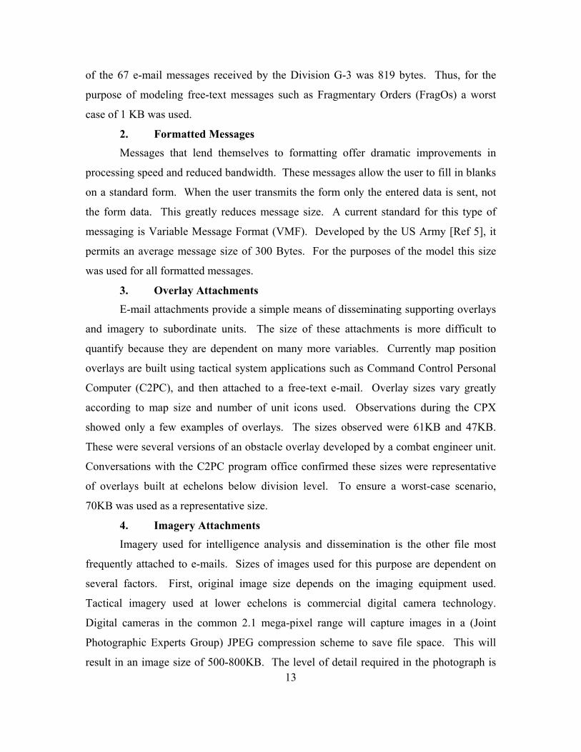
2. Program Generator The Program Generator shown in Figure 7 is used to produce items. In the case of
this model, each item produced is a message. The Program Generator takes its cue from
the Executive Block and generates a message based on output time each time the
executive increments the count. Program Generators are used to model message outputs
from each network node in Figure 4. Messages from nodes with more than one instance
(i.e. Infantry Company X 3) are aggregated into a single program generator. Messages
with similar distribution times (daily or hourly) are grouped together into separate
program generators to facilitate the appropriate refresh time. Voice and video links are
also given their own program generator with refresh rates of 1 second to model the links
as dedicated bandwidth.
Within the program generator initial message attributes are set. The attribute
“Output Time” is based on the transmission intervals assigned in Appendix A. All output
times are in seconds and can be converted to hours. Messages with multiple output times
were randomly assigned over the appropriate periods, either daily or hourly. The next
attribute assigned is “Message Type” which is assigned from the “Msg #” column in
Appendix A. The last attribute assigned in the program generator is “# sent” which is
assigned from Appendix A, column TX #.
20
startstartVV
Figure 7. The Program Generator and Dialog Box.
3. Combine Block Messages flow out of the program generator into a combine block (Figure 6)
where they retain their identities but are combined into a single stream.
Figure 8. Combine Block.
21

4. Set Message Size Blocks After leaving the Combine Block, messages are assigned another attribute
“message size”, using the Appendix A data from the “size (bits)” column. This attribute
is set using a series of blocks that will perform an “if X then Y” operation (Figure 9).
“X” being the assigned “msg#” and “Y” being the size in bits. This ensures multiple
instances of a message are assigned the same size.
A
Set A
Message Size
x y
A∆
Get A
Figure 9. Set “Message Size” Blocks and Dialog Box.
22

5. # Sent Block The last attribute set is # sent (Figure 10). Though originally assigned in the
program block this action actually multiplies the message by the assigned number. This
models the effect of multiple copies or addressees being assigned to the same message.
A∆
Get A
# sent
Figure 10. Set Attribute # Sent Block and Dialog Box.
6. Bandwidth Calculator Following the setting of this final attribute all messages are combined for final
processing and bandwidth allocation. During this process each message is assigned a
delay as a factor of message size / bandwidth (Figure 11). Sensors are then connected to
a plotter to plot “Message Size”, “Wait Time” and “Mean Delay” over a 24-hour period.
23

Figure 11. Message Delay Calculator.
The block-by-block description accompanying Figures 4 through 9; is intended to
clarify the purpose of the components and methods used in the Extend™ Model.
Additionally, the Extend™ modeling tool offers a variety of building blocks applicable to
a wide variety of systems. Once a user overcomes the initial learning curve, Extend™
becomes extremely intuitive and user friendly.
24

V. ANALYSIS OF RESULTS
A. MODEL OUTPUT
1. Results with Voice/Video Links Voice-over-IP is slowly being implemented and accepted in the commercial
sector. It is predicted to eventually supplant dedicated voice networks sometime in the
near future. There are many advantages to this kind of network: (1) This allows
bandwidth to be used more efficiently because dedicated voice nets no longer sit idle
when not in use. (2) Workstation applications can process both data and voice. (3) The
establishment and management of multiple narrowband nets is no longer required. The
model was first run with all voice and video program generators connected and
bandwidth set at 1.544 Mbps. The results are illustrated in the graph generated by the
plotter in Figure 12.
The Y1-axis on the left side of the graph displays delay time. The Y2-axis on the
right of the graph displays message size. The X-axis provides the time scale displayed in
seconds over a 24-hour period. Average delay time was .086 seconds as displayed in
Figure 13.
25

Y1 X Y2
Figure 12. Graph of Results with Voice Links at 1.544 Mbps.
26
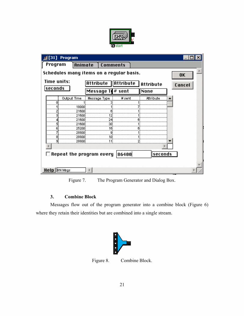
Figure 13. Timer Dialog Box for 1.544Mbps.
2. Results without Voice/Video Links The model was built with the voice links transmitting a 16 Kilobit message per
second. This provides a representation of dedicated voice links transmitting in an
always-on mode. Given that voice-over-IP may not be a near term option the model was
also run without voice and video links to observe bandwidth effects of only data
messages. The bandwidth calculator was set to 512 Kbps. With roughly one-third the
bandwidth all data messages are transmitted with almost one half the delay (.045
seconds) of the first iteration. The results show a significant reduction in bandwidth
requirements when transmitting only data messages.
27

Y1 X Y2
Figure 14. Graph of Results Without Voice Links at 512 Kbps.
Figure 15. Timer Dialog Box for 512 Kbps.
28

Y1 Y2
X
Figure 16. Graph of Results Without Voice Links at 256 Kbps.
Figure 17. Timer Dialog Box for 256 Kbps.
29

A “congestion spike” was identified at time, 17924 seconds. This was a result of
high traffic volume at a single point in time. This caused the message queue to fill to a
point where every message sent during this time incurred a significant increase in delay.
The simulation run for 512 Kbps incurred a maximum delay of 3.53 seconds, while the
256 Kbps run incurred a maximum delay of 20.35 seconds. This becomes important as
we examine Table 4 in the C4ISP [Ref. 4]. The table assigns timeliness requirements for
critical messages. Here, messages have been assigned acceptable delay times based on
their priority. Of messages identified in this table, the highest priority messages require a
delay of no more than 2 seconds. Neither the 512K run nor the 256K run would meet this
requirement if these high priority messages were to be transmitted during this congestion
spike. The assignment of message priorities and Quality of Service (QoS) protocols is
one way to affect improvements in these delays, but is beyond the scope of this study. A
final run was conducted at 2.56 Mbps. This was the minimum bandwidth required to
ensure minimum timeliness requirements [Ref. 4] were met. At this bandwidth the
maximum delay observed was 2.035 seconds (Figure 18). Following this run,
voice/video links were reconnected and the simulation run again with the bandwidth set
at 2.56 Mbps. The results of this run show the efficiencies to be gained by the IP
communications model. The maximum delay observed during the congestion spike was
only 2.19 seconds or a difference of .155 seconds from the previous run.
30

Y1
X Y2
Figure 18. Graph of Results Without Voice Links at 2.56 Mbps.
B. PROTOCOL OVERHEAD
This model attempts to be independent of current networks or systems however, it
must be pointed out that message size data was gathered from current program sources
using current protocols and operating systems. Each protocol adds to the overall system
overhead. Overhead is defined as bits added to datagrams to enable delivery or
processing within a specified network or system. Increases in overhead are realized as
additional protocols such as wireless network protocols are added. This has an
immediate impact on message size and consequently decreases network performance.
Also, security protocols can add to overhead. Implementation of encryption or Virtual
Private Networks (VPN) can have significant impacts on overhead. All of these variables
must be considered in detail as requirements for future systems are examined.
31

THIS PAGE INTENTIONALLY LEFT BLANK
32

VI. CONCLUSIONS
The AAAV(C) will soon be a centerpiece of the USMC command and control
infrastructure. Identifying the bandwidth requirements to support an infantry battalion
network is the first step in providing concise, comprehensive requirements documents to
support the procurement and development of this and future systems. This thesis
addresses one methodology for examining network bandwidth requirements in tactical
scenarios.
The STOM, maneuver ashore phase was used as the basis for examining a worst-
case scenario for a notional infantry battalion network. An infantry battalion Combat
Operations Center aboard an AAAV(C) is modeled and doctrinal messages identified for
this network. Data was then collected on the size of each message. A group of Subject
Matter Experts (SME’s) was assembled and opinions gathered concerning the
transmission intervals for each message. This data is assembled and recorded in
Appendix A and can provide the basis for future detailed examinations of infantry
battalion networks. This data was then used to populate a model created with Extend®
modeling and simulation software. Results from this effort show bandwidth requirements
for an infantry battalion, tactical COC, without voice/video links or QoS protocols can be
met with a AAAV(C) bandwidth of 2.56 Mbps. Including voice/video links only
increases the maximum message delay incurred by .0155 seconds.
The current systems aboard the AAAV(C) cannot meet the 2.56 Mbps bandwidth
required to accommodate the message traffic identified by the SME’s. The bottleneck in
the present system is the current reliance on multiple, stove-piped, bandwidth limited
systems. What is required in future AAAV(C) variants, in order to meet the message
loads identified in this study, are systems at the infantry battalion nodes that can link to a
single high bandwidth transceiver that has a minimum bandwidth of 2.56Mbps.
Future tactical communications systems should include the examination of the
feasibility of high bandwidth IP based systems. Their efficient use of bandwidth will
33

provide the most flexibility and growth as data products grow in size and these products
are pushed to lower tactical echelons.
34

APPENDIX A. DATA SET
Unit Staff Position
Msg # TX TX# RX Message Size (Bytes)
Size (bits)
Transmission Interval
Infantry Regt
S-3 1 X 1 X Op Order/Overlay
70KB 573440 1 per day
2 X 1 X FragO 1KB 8192 1 per day 3 X SITREP 300B 2400 2 per day 4 X X Friendly
Tracks 400B 3200 Constant
FSC 5 X 1 Target List 1KB 8192 1 per day 6 X List of Targets 1KB 8192 1 per day 7 X 1 FS Overlays 70KB 573440 1 per day 8 X 1 X TARBUL 1KB 8192 1 per day DASC 9 X 1 ATO 70KB 573440 1 per day 10 X JTARS 300B 2400 4 per day 11 X Assault
Support Requests
300B 2400 3 per day
S-2 12 X 1 INTSUMS 1KB 8192 2 per day 13 X INTREPS 850B 6800 12 per day 14 X 1 IPB
Data/Overlay 70KB 573440 1 per day
15 X UAV Video 112Kbps
112000 Constant
16 X 1 X IMAGERY 140KB 1146880
6 per day
17 X X Enemy Tracks 400B 3200 Constant 18 X 1 WX REP 1KB 8192 1 per day S-4 19 X LOGREPS 1KB 8192 1 per day 20 X 1 X LOG Overlays 70KB 573440 1 per day 21 X LOG Requests 300B 2400 24 per day 22 X MEDEVAC 300B 2400 10 per day 23 X PERSO
Reports 1KB 8192 1 per day
Infantry Bn
S-3 1 X 7 X Op Order/Overlay
70KB 573440 1 per day
2 X 7 X FragO 1KB 8192 2 per day 3 X 1 X SITREP 300B 2400 2 per day 4 X X Friendly
Tracks 400B 3200 Constant
FSC 5 X Target List 1KB 8192 1 per day 6 X 1 List of Targets 1KB 8192 1 per day 7 X ATO 70KB 573440 1 per day 8 X 7 X FS Overlays 70KB 573440 2 per day 9 X 1 TARBUL 1KB 8192 1 per day 10 X 1 Fire Plan 1KB 8192 1 per day 11 X 1 X JTARS 300B 2400 4 per day 12 X 1 X Assault
Support Requests
300B 2400 3 per day
35

Unit Staff Msg # TX TX# RX Message Size Size Transmission Position (Bytes) (bits) Interval
13 X 9-Line Brief 300B 2400 4 per hour 14 X Call for Fire 300B 2400 10 per hour 15 X End of
Mission and Surv
300B 2400 10 per hour
S-2 16 X 6 X INTSUMS 1KB 8192 2 per day 17 X INTREPS 850B 6800 12 per day 18 X 6 X IPB
Data/Overlay 70KB 573440 1 per day
19 X SPOT/SALUTE REPS
300B 2400 10 per hour
20 X OBSTACLE REPORT
300B 2400 6 per day
21 X UAV Video 112000 Constant 22 X 3 X IMAGERY 140KB 114688
0 4 per hour
23 X X Enemy Tracks 400B 3200 Constant 24 X 6 X WX REP 1KB 8192 1 per day 25 X 1 X MIJI REPORT 300B 2400 6 per day S-4 26 X 1 X LOGREPS 1KB 8192 1 per day 27 X 6 LOG Overlays 70KB 573440 1 per day 28 X LOG Requests 300B 2400 14 per day 29 X MEDEVAC 300B 2400 12 per day 30 X 1 X PERSO
Reports 1KB 8192 1 per day
Infantry Co
CP 1 X Op Order / Overlay
70KB 573440 1 per day
2 X Frag O 300B 2400 2 per day 3 X 2 SPOT/SALUT
E REP 300B 2400 2 per hour
4 X 3 SITREP 300B 2400 2 per day 5 X X Friendly
Tracks 400B 3200 constant
6 X 1 X MIJI REPORT 300B 2400 2 per day 7 X 1 Log Requests 300B 2400 8 per day FO 8 X 1 Call for Fire 300B 2400 6 per hour 10 X 1 End of
Mission and Surv
300B 2400 6 per hour
FAC 11 X 1 JTAR 300B 2400 2 per day 12 X 1 Assault
Support Requests
300B 2400 3 per day
13 X 1 9-Line Brief 300B 2400 2 per hour 14 X 1 MEDEVAC 300B 2400 8 per day Artillery Bn
FDC 1 X Op Order/Overaly
70KB 573440 1 per day
2 X FS Overlays 70KB 573440 2 per day 3 X Target List 1KB 8192 1 per day 4 X TARBUL 1KB 8192 1 per day 5 X Fire Plan 1KB 8192 1 per day
36

Unit Staff Msg # TX TX# RX Message Size Size Transmission Position (Bytes) (bits) Interval
6 X INTSUMS 1KB 8192 2 per day 7 X 1 SITREPS 300B 2400 2 per day 8 X 1 FIRECAP 300B 2400 3 per day 9 X Call for Fire 300B 2400 6 per hour 10 X Adjustment 300B 2400 18 per hour 11 X End of
Mission and Surve
300B 2400 6 per hour
12 X 1 Ammo Count 1KB 8192 4 per day SACC / NSFS
LNO 1 X FS Overlays 70KB 573440 2 per day
2 X 1 FIRECAP 300B 2400 2 per day 3 X Target List 1KB 8192 1 per day 4 X Fire Plan 1KB 8192 1 per day 5 X Call for Fire 300B 2400 2 per hour 6 X Adjustment 300B 2400 6 per hour 7 X End of
Mission and Surv
300B 2400 2 per hour
81mm Mortar Plt
CP 1 X Op Order/Overlay
70KB 573440 1 per day
2 X FS Overlays 70KB 573440 1 per day 3 X X Friendly
Tracks 400B 3200 constant
4 X 1 SITREP 300B 2400 2 per day 5 X 1 FIRECAP 300B 2400 3 per day 6 X INTSUMS 1KB 8192 2 per day 7 X Call for Fire 300B 2400 2 per hour 8 X Adjustment 300B 2400 6 per hour 9 X End of
Mission and Surv
300B 2400 2 per hour
10 X 1 MEDEVAC 300B 2400 1 per day 11 X 1 Log Requests 300B 2400 2 per day CAAT Teams
TM/LDR 1 X FragO 1KB 8192 1 per day
2 X 1 SPOT/SALUTE REP
300B 2400 3 per hour
3 X X Friendly Tracks
400B 3200 constant
4 X 1 SITREP 300B 2400 2 per day 5 X 1 Log Requests 300B 2400 2 per day 6 X 1 MIJI Report 300B 2400 2 per day 7 X 1 Call for Fire 300B 2400 2 per hour 8 X 6 Adjustment 300B 2400 6 per hour 9 X 1 End of
Mission and Surv
300B 2400 2 per hour
10 X 1 9-Line Brief 300B 2400 1 per hour 11 X 1 MEDEVAC 300B 2400 1 per day
37

Unit Staff Msg # TX TX# RX Message Size Size Transmission Position (Bytes) (bits) Interval
Scout/Sniper Tm
TM LDR 1 X FragO 1KB 8192 1 per day
2 X 5 SPOT/SALUTE REP
300B 2400 5 per hour
3 X X Friendly Tracks
400B 3200 constant
4 X 2 SITREP 300B 2400 2 per day 5 X 2 Log Requests 300B 2400 2 per day 6 X 2 MIJI Report 300B 2400 2 per day 7 X 2 Call for Fire 300B 2400 2 per hour 8 X 6 Adjustment 300B 2400 6 per hour 9 X 2 End of
Mission and Surv
300B 2400 2 per hour
10 X 1 9-Line Brief 300B 2400 1 per hour
38

LIST OF REFERENCES
1. Operational Requirements Document for the Advanced Amphibious Assault Vehicle (AAAV), (No. MOB 22.1), September 13, 2000.
2. C2 Platform Study, C4ISR Directorate, Marine Corps Systems Command, 27 November 2000.
3. Advanced Amphibious Assault Vehicle (AAAV) Command, Control, Communications, and Intelligence Support Plan (C4ISP), Version 2.2, 27 October 2000.
4. Extend v3 User's Guide and Programmer's Reference, Imagine That Inc., 1997.
5. Ship to Objective Maneuver Concept of Operations (Draft), Marine Corps Combat Development Command, August 2000.
6. Concept of Employment (COE) for the Advanced Amphibious Assault Vehicle (Command), (AAAV(C)).
39

THIS PAGE INTENTIONALLY LEFT BLANK
40

INITIAL DISTRIBUTION LIST
1. Defense Technical Information Center Ft. Belvoir, Virginia
2. Dudley Knox Library Naval Postgraduate School Monterey, California
3. Advanced Amphibious Assault AAAV Technology Center
Woodbridge, Virginia
4. Marine Corps Combat Development Center C4I Branch, Requirements Div (C442) Quantico, Virginia
5. Marine Corps Representative
Naval Postgraduate School Monterey, California
6. Director, Training and Education, MCCDC, Code C46 Quantico, Virginia
7. Director, Marine Corps Research Center, MCCDC, Code C40RC
Quantico, Virginia
8. Marine Corps Tactical Systems Support Activity (Attn: Operations Officer)
Camp Pendleton, California
9. Professor John Osmundson, Information Systems Technology Naval Postgraduate School
Monterey, California
41

10. Dave Adamiak, Electrical Engineering Department Naval Postgraduate School Monterey, California
42