Webinar Series APTA Standards Quarterly Webinar … Webinar Series APTA Standards Quarterly Webinar...
70
1
Transcript of Webinar Series APTA Standards Quarterly Webinar … Webinar Series APTA Standards Quarterly Webinar...

1

2
Webinar Series
APTA Standards Quarterly
Webinar SeriesPresented by
APTA Brake and Chassis Working Group
Disc Brake Wheels On Inspection
January 26, 2017

Moderator
Frank Forde
Equipment Maintenance Instructor
Los Angeles Metropolitan Transportation
Authority
Los Angeles, CA
3
Jerry Guaracino
Assistant Chief Engineering Officer – Bus
Engineering
Southeastern Pennsylvania Transportation
Authority (SEPTA)
Philadelphia, PA
Presenter

Panelists
Brian D. Markey
President
Custom Training Aids Inc.
La Verne, CA
4
John Brundage
Foreman, Acting Project Manager
Massachusetts Bay Transportation Authority
(MBTA)
Boston, MA

Objective
Welcome to today’s webinar in which you will learn
how to perform a Wheels On Disc Brake Inspection.
We will cover disc brake operation, inspection
points, visual and functional checks.
5
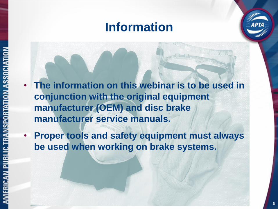
Information
• The information on this webinar is to be used in
conjunction with the original equipment
manufacturer (OEM) and disc brake
manufacturer service manuals.
• Proper tools and safety equipment must always
be used when working on brake systems.
6
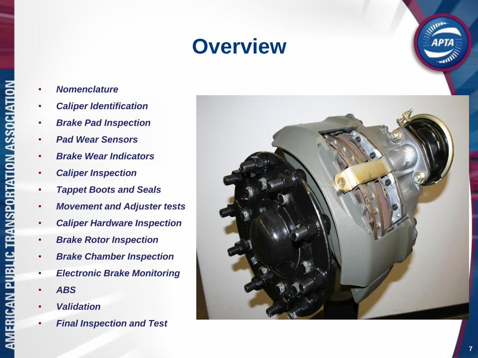
Overview
• Nomenclature
• Caliper Identification
• Brake Pad Inspection
• Pad Wear Sensors
• Brake Wear Indicators
• Caliper Inspection
• Tappet Boots and Seals
• Movement and Adjuster tests
• Caliper Hardware Inspection
• Brake Rotor Inspection
• Brake Chamber Inspection
• Electronic Brake Monitoring
• ABS
• Validation
• Final Inspection and Test
7

Nomenclature
8
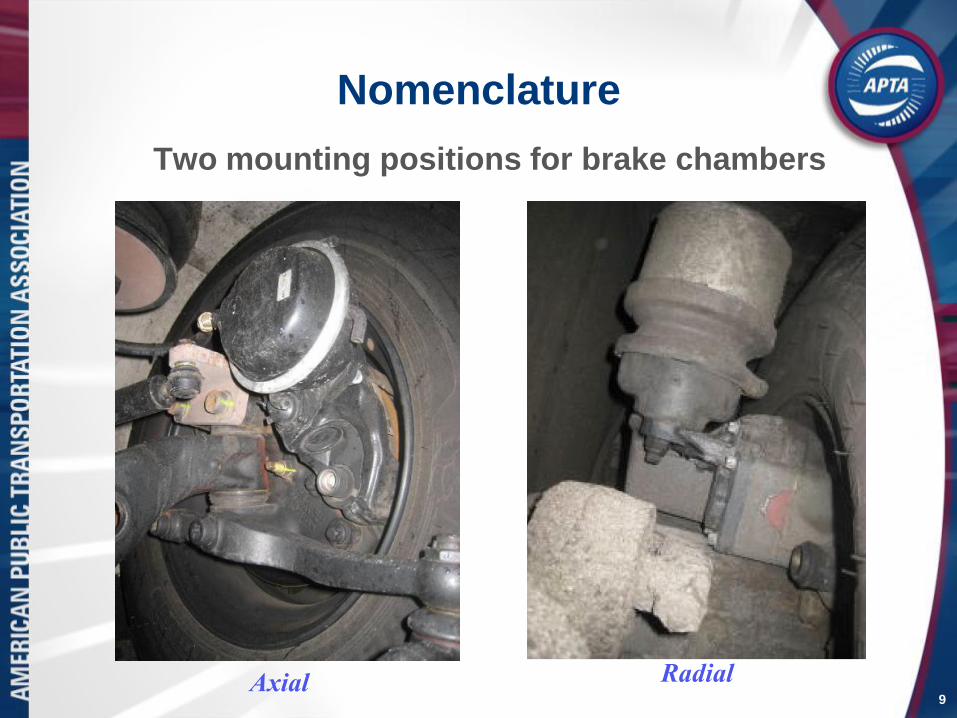
Nomenclature
Two mounting positions for brake chambers
9Axial Radial

Caliper Identification
Knorr Bremse SN7 Caliper
Meritor EX225 Caliper
10
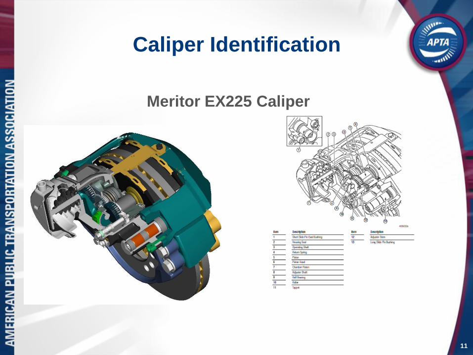
Caliper Identification
Meritor EX225 Caliper
11
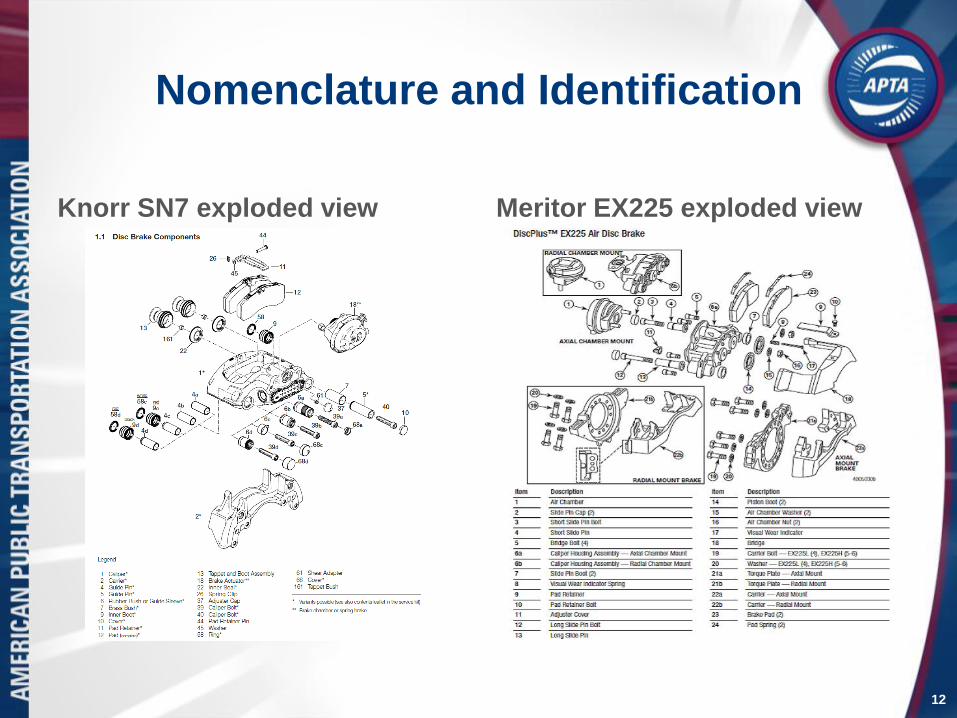
Nomenclature and Identification
Knorr SN7 exploded view Meritor EX225 exploded view
12

Nomenclature
Knorr-Bremse Timing
Chain Meritor EX225 Adjuster
13
For illustration purposes only. Do not disassemble. Not serviceable.

Inspection – Other types of brake
assembly damage
Damage caused by a missing
pad retainer strap
Damaged rim and brake
chamber caused by a missing
pad retainer strap
14

Brake Pad Inspection
15
• Inspect caliper for:
• Missing brake pads
• Loose friction material on pad backing plate
• Brake pad thickness
• Overheated brake pads
• Note: Brake pad thickness of 1/16 inch (1.6mm) or
worn to wear sensor requires immediate reline.
• Caliper mounted wear indicator or electronic wear
indicator is acceptable for measuring pad thickness.

Brake Pad Inspection
16
Brake pads can usually be inspected using a mirror and flashlight

Brake Pad Inspection will require a mirror.
Check for uneven pad wear, wear beyond
tolerance, taper and broken pads.
Brake pad uneven wear (taper) Brake pads showing unacceptable
wear—note edges
17
The cause of improper pad wear must be identified and corrected.
Brake Pad Wear Indicators
• Electronic brake pad wear indicators:
• Warn operator prior to maximum wear limit and
end of pad life
• Account for rotor wear
• Mechanical brake pad wear indicators:
• Measure pad thickness based on a pre-
determined rotor thickness of 45 mm
• Do not account for rotor wear
18

Electronic Pad Wear Sensors
19
In-pad wear sensor In-pad wear sensor and
wiring harness
Brake Pad Wear Sensors
• Electronic brake pad wear indicators
• Have a sensing wire embedded in the friction
material at the minimum service thickness
• When friction material wears to minimum
thickness, sensor wire contacts rotor creating a
electrical path to ground and illuminates a
service warning requiring further inspection
• As the friction material wears further the sensor
wire breaks creating an open circuit illuminating
an end of life warning
• Brake reline should be performed
20

Wear Sensor
21
Brake pad worn beyond tolerance—note sensor wear

Brake Pad Wear Indicators
• Mechanical brake pad wear indicators
• Measure brake pad thickness based on caliper
position and new rotor thickness of 45mm
• As friction material and rotor wear, indicator
moves providing a general reference of
remaining friction material
• Don’t compensate for rotor wear
• Are less accurate when new pads are installed
on used rotors
• Require visual inspection of pads and rotor
more frequently
22

Meritor EX225 Wear Pin Inspection
23
The pad/rotor wear can be visually determined
without removing the wheel by viewing the
protrusion of the wear indicator pin. If pin protrusion
is less than 0.16 inch (4mm) the pads require further
inspection or replacement.
Pad wear indicator pin Pad wear indicator measurement
using a tire tread depth gauge

New Style Meritor Wear Indicator Pin
24

Knorr SN-7 Guide Pin Inspection
25
• Dirt, road salts, and debris can obstruct view of guide pin
• Care should be exercised to insure solid rubber bushing is not mistaken for
stainless steel guide pin
• On early calipers, pin protrusion can be measured to track pad and rotor wear
for determining fleet pad mileage/life expectations

Knorr SN-7 Guide Pine Inspection
26
Early Knorr SN-7 Disc brakes are equipped with solid rubber
bushing style wear indicators, which provide an indication of
when to schedule a full wheel off brake inspection. The
thicknesses of BOTH the pads/rotors will affect the wear
indicator position.

Knorr SN-7 Guide Pin Inspection
27
On both front and rear axle, road and curb sides, inspect the
position of the guide pin compared to the solid rubber
bushing.
If pad wear indicator protrudes less than 1mm (. 040"), then
the wheels must be removed to measure pads and rotors on
that axle (both sides).
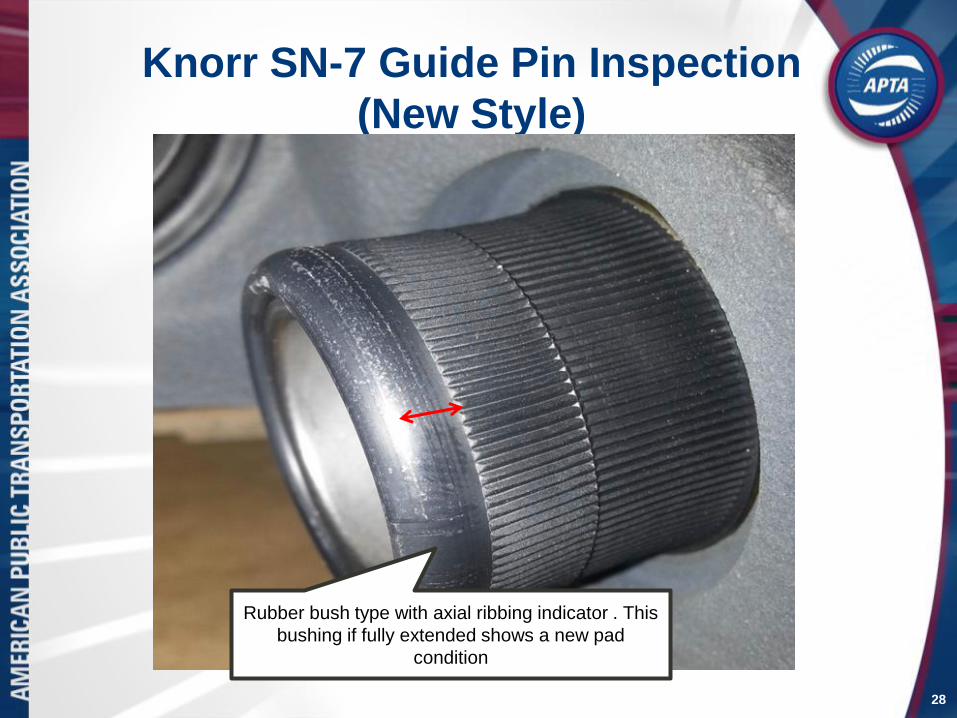
Knorr SN-7 Guide Pin Inspection
(New Style)
Rubber bush type with axial ribbing indicator . This
bushing if fully extended shows a new pad
condition
28

Knorr SN-7 Guide Pin Inspection
(New Style)
This bushing is
almost fully
retracted
indicating a
worn pad and /
or rotor
HOLD
FOR
RELINE
29
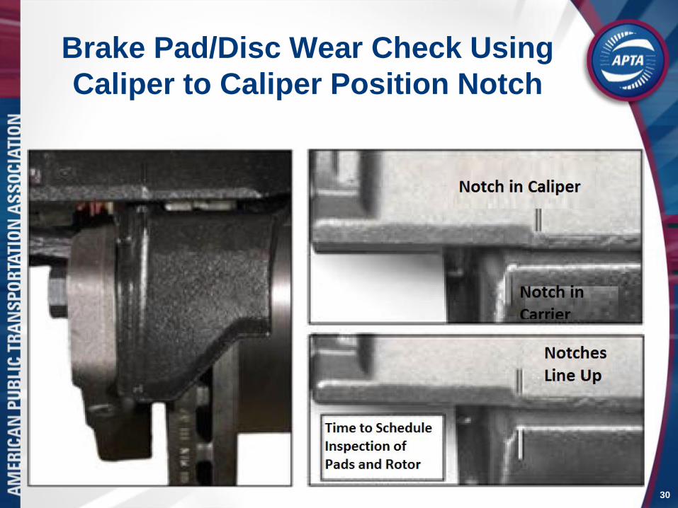
Brake Pad/Disc Wear Check Using
Caliper to Caliper Position Notch
30

Knorr SN-7 Caliper to Carrier Notch
31
The pad/rotor wear can be visually determined
without removing the wheel by viewing the position
of the caliper position “P” compared to the carrier
marking “R”
Caliper position with new pads and
rotor
Caliper position when pads or rotor
require further inspection

Caliper Inspection
• Inspect caliper mounting bolts for rust, movement, or
signs of looseness.
• Inspect caliper for heavy rust and damage which may
indicate a non-working or overheated brake
• Check slide pin and bushing wear by pushing up and
down checking for excessive movement.
• Caliper should move freely along slide pins with
minimum sideways or vertical movement.
• Excessive movement is a sign of worn or loose
bushings and slide pins.
32
Springs

Caliper Inspection
33
Check for loose or missing mounting hardware

Thermal OverloadBelow are examples of Thermal Overload
which is an indication of excessive heat
caused by dragging brakes. The cause must
be identified and corrected
Below are examples of brake
assemblies exhibiting normal operating
conditions
34
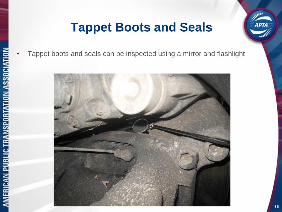
Tappet Boots and Seals
• Tappet boots and seals can be inspected using a mirror and flashlight
35
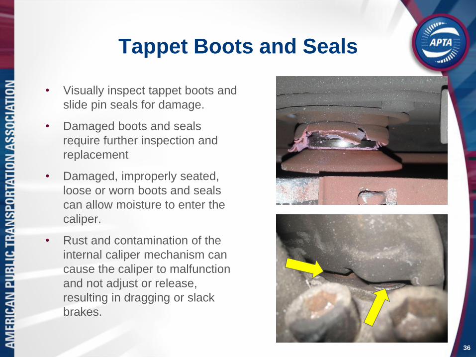
Tappet Boots and Seals
• Visually inspect tappet boots and
slide pin seals for damage.
• Damaged boots and seals
require further inspection and
replacement
• Damaged, improperly seated,
loose or worn boots and seals
can allow moisture to enter the
caliper.
• Rust and contamination of the
internal caliper mechanism can
cause the caliper to malfunction
and not adjust or release,
resulting in dragging or slack
brakes.
36

Caliper Movement Test
37
The caliper movement test is done to make sure that the caliper slides on its pins and
there is sufficient clearance between the rotor and brake pads

Caliper Inspection
• Caliper Adjustment
• Attach dial indicator to torque plate or bus frame.
• Dial indicator reading should be taken at slide pin
bearing cap.
• Check brake adjustment by sliding caliper back
and forth by hand along the slide pins.
• If caliper slides more than 0.08 inch (2mm) the
brake is out of adjustment and requires further
inspection or replacement.
38
Springs

39
Checking Caliper Adjustment
Also referred to as “free-running clearance”

40
Adjuster Location

Adjusting Screw Seal and Cap
41
• Inspect
adjusting screw
cap for
missing,
damage and
tight seal
• Visually inspect
adjusting screw
internal seal for
damage

42
Adjuster Protective Cap

Knorr Bremse Shear Adapter
43
The Knorr Bremse shear adapter is
designed to shear if excessive torque is
required to turn the adjuster
The shear adapter
(above) fits over the
splines on the
Knorr Bremse
adjuster (right)
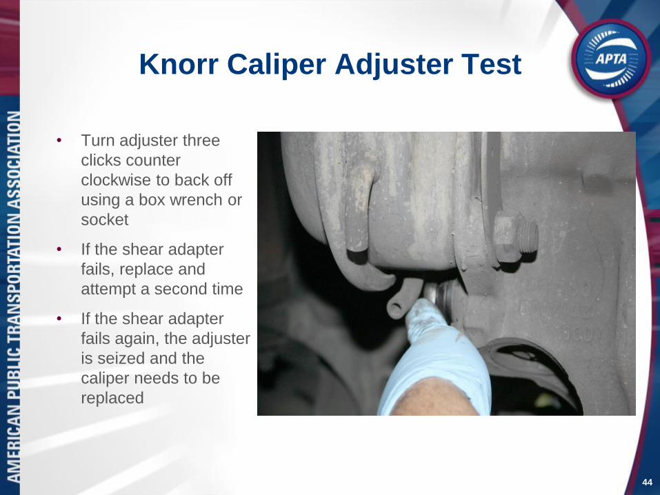
Knorr Caliper Adjuster Test
• Turn adjuster three
clicks counter
clockwise to back off
using a box wrench or
socket
• If the shear adapter
fails, replace and
attempt a second time
• If the shear adapter
fails again, the adjuster
is seized and the
caliper needs to be
replaced
44
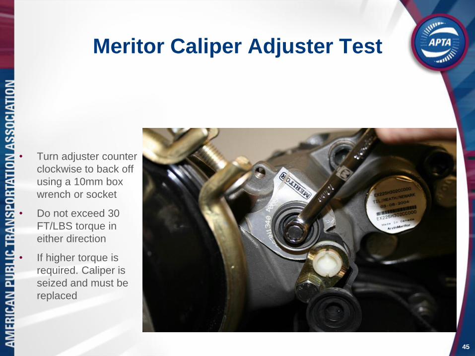
Meritor Caliper Adjuster Test
• Turn adjuster counter
clockwise to back off
using a 10mm box
wrench or socket
• Do not exceed 30
FT/LBS torque in
either direction
• If higher torque is
required. Caliper is
seized and must be
replaced
45
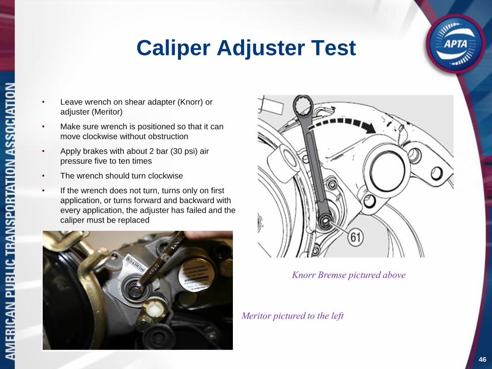
Caliper Adjuster Test
• Leave wrench on shear adapter (Knorr) or
adjuster (Meritor)
• Make sure wrench is positioned so that it can
move clockwise without obstruction
• Apply brakes with about 2 bar (30 psi) air
pressure five to ten times
• The wrench should turn clockwise
• If the wrench does not turn, turns only on first
application, or turns forward and backward with
every application, the adjuster has failed and the
caliper must be replaced
46
Knorr Bremse pictured above
Meritor pictured to the left
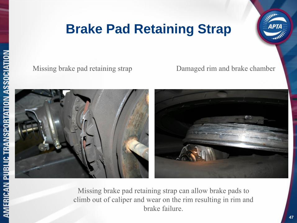
Brake Pad Retaining Strap
47
Missing brake pad retaining strap
Missing brake pad retaining strap can allow brake pads to
climb out of caliper and wear on the rim resulting in rim and
brake failure.
Damaged rim and brake chamber

Brake Pad Retaining Strap
48
Inspect caliper brake pad retaining strap and fastener.
Meritor brake pad retaining strap correctly
installed with pad anti-rattle springs in place.

Brake Pad Retaining Strap
49
Inspect caliper brake pad retaining strap and fastener.
Knorr Bremse brake pad retaining strap correctly
installed with pad anti-rattle springs in place.

Brake Rotor Inspection
50
• Visually inspect rotor for:
• Wear
• Overheating
• Heat checks
• Cracks
• Grooves
• Discoloring
• Damage
• Contamination

Brake Rotor Inspection
51
Visually inspect swept area of rotor for defects and damage.
Only the inner side of the rotor can be easily inspected so extra care
should be exercised to check as much of the rotor as possible.

Brake Rotor Inspection
52
Blue bands or marks indicate the rotor was very hot

Brake Rotor Inspection
53
Rusting on rotor surface indicating possible inoperative brakes
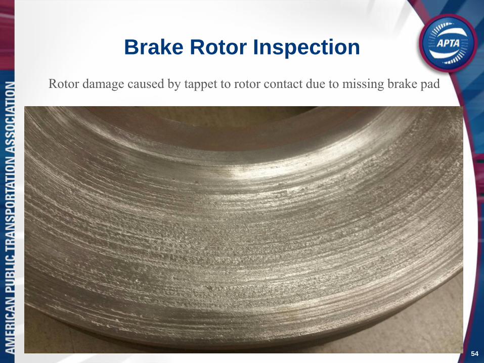
Brake Rotor Inspection
54
Rotor damage caused by tappet to rotor contact due to missing brake pad

Brake Rotor Inspection
55
Grooves deep enough that the rotor thickness, when measured in the grooves, is
thinner than the minimum allowable rotor thickness will require a rotor
replacement. The cause must be identified and corrected.

Brake Rotor Inspection
56

Brake Rotor Inspection
57

Brake Rotor Inspection
58
Check rotor for damage and excessive wear

Brake Rotor Inspection
59
• Brake rotors should be checked for contamination
from:
• Leaking axle grease or oil seals
• Road debris and contaminants
• Note: Oil and grease contaminated rotors should be
replaced as the oil and grease can never be fully
removed from the metal and will cause unbalanced
brakes

Brake Rotor Inspection
60
Rotor contamination from grease or oil will require rotor replacement

Brake Rotor InspectionSome Meritor rotors have different swept area thickness with the inboard
swept area thinner than the outboard and should not be confused for
wear. (picture for reference only)
61

Brake Chambers
• With the brake system at governor
full cut-out, release parking brake
(when applicable) then apply service
brakes and listen for an air leak
• Any air leaks will deem the vehicle
out of service until repairs are made
• Chambers must:
Be same size
Contain cage tool and sealing plug
Display no evidence of contact with
wheel, body, suspension, or frame
Mounting nuts are tight and
chamber is secure
62
Front Service Brake Chamber
Rear Spring Brake Chamber

Brake Chambers
• Ensure the bottommost housing plug is
removed
• Failure to remove a plug from the non-
pressure housing will cause a slow
releasing, dragging brake
• For brake chambers equipped with
elbows, the chamber must be oriented in
such a way that the two elbows will easily
allow water and contaminants to drain
from the chamber
63
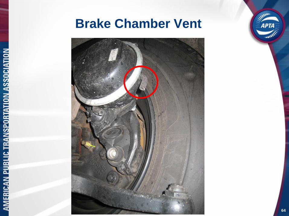
Brake Chamber Vent
64

Brake Chamber Vent
65
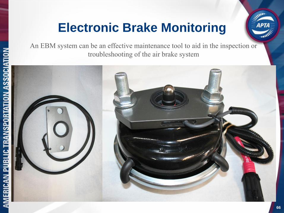
Electronic Brake Monitoring
66
An EBM system can be an effective maintenance tool to aid in the inspection or
troubleshooting of the air brake system

ABS Sensor
67
Inspect ABS sensor mounting, wiring, and adjustment. Replace as necessary.

Validation
68
Perform a brake performance test to verify satisfactory brake operation

Final Inspection and Test
• Perform a brake performance test to
verify satisfactory brake operation
• Document inspection results
• Return bus to service if no repairs are
needed
• Schedule repairs if required
69
Frequency of wheel on inspections will vary depending on the operating
environment but should not be limited to pad change intervals
70
Any Questions?
Please e-mail the questions to
The APTA Brake and Chassis Work Group and
the APTA Bus Standards Committee would like
to thank you for joining our Webinar.
Pictures, drawings and technical information courtesy of MAN, ZF, Meritor, Knorr-Bremse, Bendix, LA Metro, Omnitrans, MBTA,
Custom Training Aids, Link Engineering, and other members of the APTA Brake and Chassis Work Group