Slide Deck Sage Sponsored Webcast With CFO Publishing 06-25-15

Thank you for attending today’s
webcast sponsored by AIRVAC.
Before we begin the webcast, please
enjoy this message from today’s
sponsor.
Sponsored by Presented by

Sponsored by
Presented by
Jeff Gilbert, P.E.
Dan Burden, Ph.D., P.E.
An Energy Cost Comparison –
Vacuum & Gravity Sewer Systems
Thursday, May 30th, 2013
Presented by

Copyright
This presentation is protected by United States and International
copyright laws. Reproduction, distribution, display and use of the
presentation without written permission of ZweigWhite, CE News,
the sponsor, or the speakers is prohibited. © ZweigWhite 2013

Presenters
Speakers: Jeff Gilbert, P.E. Associate WadeTrim
Dan Burden, Ph.D., P.E. Senior Associate WadeTrim
Moderator: Bob Drake Editor-in-Chief, CE News & RAI ZweigWhite

Wade Trim’s Involvement w/Vacuum Sewers
• Florida Keys Design Experience
• Key Largo Wastewater Treatment District, Area C
• Middle Plantation Key, Islamorada
• Owner’s Representative – Islamorada Wastewater Program (DBO)
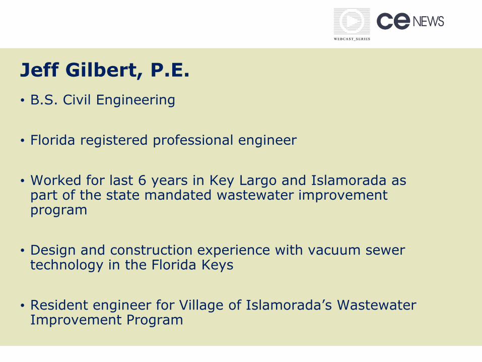
Jeff Gilbert, P.E.
• B.S. Civil Engineering
• Florida registered professional engineer
• Worked for last 6 years in Key Largo and Islamorada as part of the state mandated wastewater improvement program
• Design and construction experience with vacuum sewer technology in the Florida Keys
• Resident engineer for Village of Islamorada’s Wastewater Improvement Program

Dan Burden, Ph.D., P.E.
• Ph.D. and Master in Civil Engineering
• Florida registered professional engineer
• 25+ years of consulting experience in FL • Technical Reviewer for WEF Manual of
Practice FD -12 “Alternative Sewer Systems” • Program Manager for Sarasota County
Septic Tank Replacement Program • Technical Review Committee Member for
Islamorada Wastewater Program (Present)

Learning Objectives
• Basic understanding of sewer collection technologies
• Operational theory of gravity and vacuum sewer systems
• Major components used in designing a sewer collection system
• Evaluation of power usage at a conventional wastewater lift station and a vacuum pump station
• Comparison of power usage and identification of energy savings

Presentation Outline
• Study Purpose
• Sewer Collection Technologies
• Design & Construction Components
• Study Location
• Comparative Methodology
• Analysis Results
• Conclusions

Study Purpose
• Compare vacuum power costs against Water Environment
Federation (WEF) published data
• Determine if vacuum sewers require more or less energy for
operation than a gravity sewer system in a similar sized
service area
• Provide accurate
power costs for future
vacuum projects and
O&M budgets

Part 1 – Jeff Gilbert, P.E.
• Vacuum Sewer System Components
• How A Vacuum Sewer Works
• Gravity Sewer Collection Systems

Vacuum Sewer System Components
Valve
Pits
Vacuum Mains
Vacuum Station

•13
Vacuum System Schematic
Division Valve
Valve Pit
Force Main
Vacuum Station
Collection Piping
WWTP

How a Vacuum Sewer Works – At the House
(2) Interface valve opens and the
contents are sucked out
(1) House to
pit via gravity lateral
(3) Differential
pressure propels sewage toward vacuum station
Atmospheric air Vacuum
Positive pressure
Negative pressure

How a Vacuum Sewer Works – In the Vacuum Main
Flow comes to rest & temporarily accumulates at the low points
Sawtooth profile keeps open passageway on top of pipe
When nearby valve(s) open, flow moves toward vacuum
station
Flow
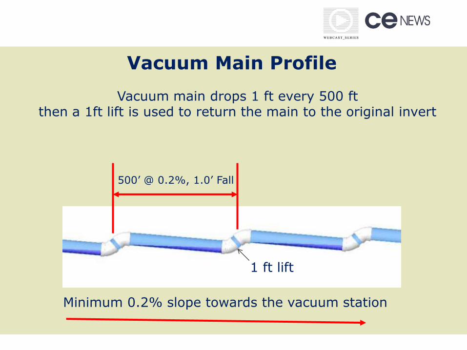
Vacuum Main Profile
Minimum 0.2% slope towards the vacuum station
500’ @ 0.2%, 1.0’ Fall
Vacuum main drops 1 ft every 500 ft then a 1ft lift is used to return the main to the original invert
1 ft lift

How a Vacuum Sewer Works – At the Vacuum Station
(2) Wastewater enters the
collection tank
(1)
Vacuum pumps cycle on and off
16”–20” Hg
(3)
Sewage pumps transfer
the contents to WWTP

SEWAGE PUMPS
Sends sewage to gravity
main, force main, or WWTP
VACUUM PUMPS
Cycle to maintain
vacuum
COLLECTION TANK
is liquid and vacuum reservoir
Vacuum Station

Vacuum Pumps

Sewage Pumps & Collection Tank

Vacuum Chart Recorder
7-day Chart Recorder
Continuous Monitoring of the
System

Touch Screen and Run Meters
Interface touch screen Pump run-time meters (vacuum & sewage pumps)

Vacuum Station – Various Building Styles
Ponte Vedra Beach, FL New Bern, NC
Englewood, FL Martin Co, FL

Gregory, MI Key Largo, FL
Barnstable, MA Ocean Shores, WA

WEF Manual of Practice FD-12
Manual contains about 120 pages on vacuum
sewers • Planning
• Design
• Construction
• O&M
• System Management
• Sample Regulations

Vacuum Sewer Misconceptions
• Vacuum pumps do not operate
continuously. They cycle on/off
for an approx. 3 minutes (see
illustration w/ chart)
• Infiltration/Inflow is not a
common occurrence
• A vacuum leak will not take an
entire system down

Gravity Sewer Basics
• Minimum pipe velocity 2 fps required
• Corrosion control and protection needed due to H2S gas production
• Pumping stations are required
• Manholes are required at 300-500 ft (typical)
• Manhole designs need to address inflow/infiltration

Gravity Sewers – Lift Station Design
Lift stations – Hydraulic structures which are used to transport wastewater
Key components:
• Wet well • Pumps • Motors • Controls • Power

2 Types of Lift Stations
• Submersible Lift Stations (small to medium in size)
Generally smaller in size, < 700 gpm
Duplex pumps, usually constant speed
Wet well detention times < 20-30 mins
• Dry Pit Lift Stations (medium to large in size)
Larger stations, usually a master lift station
Variable speed pumps typically used
Wet well detention times usually < 15 mins
Standby generator system

Lift Station Illustration
Typical Gravity Sewer & Lift Station Profile

Typical Gravity Sewer System
• Advantages:
• Allows for handling of grit and solids
• By maintaining a minimum velocity, the production of H2S and methane gases can be reduced
• Disadvantages:
• Minimum slope requirements result in deep excavation
• Pumping stations are required
• Manholes are usually a source of inflow/infiltration
• Potential for manhole overflows during power failures (lift stations)

Gravity Sewers – Design & Construction
• Construction can be disruptive due to the depth of construction, multiple lift stations, and dewatering requirements
• Manholes required at set intervals, pipe intersections, changes in pipe direction and changes in pipe slopes
• Infiltration and inflow always a concern
• Buoyancy considerations
• Renewal and replacement costs associated with manholes & lift stations (corrosion problems).

Part 2 – Dan Burden, Ph.D., P.E.
• Comparative Study
• Study Location
• Methodology
• Data Analysis
• Results

Gravity vs. Vacuum Sewers
Parameter Gravity Sewer Vacuum Sewer
Pipe Size 8 to 42 inch 4 to 10 inch
Minimum Slope
0.40 ft/100-ft (8” dia) 0.037 ft/100-ft (42” dia)
0.20 ft/100-ft independent of pipe dia
Manholes
4-ft min. diameter; Spaced every 300-600 ft;
Coatings required
Manholes not required
Construction
Depth
Range from 3.0 to 6.5 feet
below surface
Shallow (30-48 inches below surface), saw-tooth
profile
Energy Costs ??? ???

Vacuum & Gravity Sewer Comparisons

Vacuum & Gravity Sewer Comparisons
• Vacuum sewers are typically installed in the right-of-way, require shallow trenches with minimal disruption; and less environmental impact
• Gravity sewers are installed along roadway centerlines; can result in short term road closures due to the depth of construction and dewatering requirements; and require more pavement restoration

Which is More Energy Intensive?
Gravity Vacuum Less power
required
0 lift station 1 Vacuum station Gravity
1 lift station 1 Vacuum station Gravity
Multiple lift stations
1 Vacuum station ???
Compared to a gravity lift station, a vacuum station has vacuum pumps in addition to sewage pumps. So the answer is obvious if the gravity layout does not require a lift station at all or if only 1 lift station is required.
But, when multiple lift stations are required to do the same job as 1 vacuum station, the answer is not so obvious.

When Multiple Stations are Required – Which Technology is More Energy Intensive:
Gravity or Vacuum?
Gravity or vacuum? Gravity or vacuum?
Even though vacuum has fewer pumps, does the additional power required for the vacuum pumps result in more power for vacuum? Or, does the pumping and re-pumping associated with gravity result in more power for gravity?

Problem: Determine the depth required for a lift station using an 8-inch diameter gravity sewer for a total distance of 11,000 linear feet based on the following assumptions: 1. Minimum slope = 0.40% min slope for 8” (4 ft/1,000 ft) 2. 3-foot minimum cover 3. Ground elevation = 5.0 ft NGVD
Gravity Main – Some Simple Math
Solution: 5.0 – (3.0 minimum cover) – (4/1,000)*(5,500) = 5-3-22 = -20 ft NGVD
Using a lift station every 5,500 LF, would result in an elevation fall of -17 ft.
------------------5,500 LF -----------

0.20% Slope 500 Ft.
1’
Min slope = 0.20% min slope (1 ft/500 ft); Lifts used to regain elevation Following this general pattern of 1 ft of fall in 500 ft followed by a 1 ft lift
allows the trench depth to stay within a foot of the starting depth throughout (3
to 4 ft typical)
With a 6” diameter vacuum main, it is possible to use (20) - 1 ft lifts and still stay within AIRVAC’s design criteria for static loss This equates to a total line length of 10,000 ft (20 lifts every 500 ft = 10,000 ft)
Vacuum Main – Some Simple Math

VPS
Potential Service Area Limits: Vacuum Sewer
In flat terrain, a single, large centrally located vacuum pump station (VPS) can serve an area roughly 3 to 4 square miles

Q/4
Q/4
Q/2 Q/2 Master
Lift Station
Same Service Area – Gravity Sewer
To serve the same 3 to 4 square mile service area with gravity sewers would require a
total of 7 lift stations
7 Lift Stations
• 4 small sized LS (each Q/4);
• 2 medium sized LS (each Q/2); and
• 1 Master LS (Q)
Q/4 Q/4

Sewer Pump Station Comparison-Typical
Parameter Gravity Sewers
Vacuum Sewers
# Stations Required
7 Lift Stations 1 Vacuum Station
# Vacuum Pumps None 2 or 3
(10 – 25 Hp/ea)
# Sewage Pumps 14
(Hp varies) 2
(Hp varies)
TOTAL 7 Pump Stations &
14 Pumps 1 Pump Station &
5 Pumps

Comparative Energy Study
2. Compare lift station power data with AIRVAC vacuum pump stations
3. Document the energy savings achieved with the use of a vacuum pump station
Objectives: 1. Evaluate existing
power usage at conventional wastewater lift stations

Study Location
• Stock Island, Florida is located at 24°34′12″N 81°44′15″W
• Approx. 1 square mile of land
• Population = 4,000 (est)
• Approx. 1,855 housing units
• Sewer utility on Stock Island is
owned and operated by Key
West Resort Utilities
Corporation
Stock Island
Key West

Why KWRU Was Chosen for this Study
• Ideal candidate for comparative evaluation
• Two different collection systems operated by same utility
• Conventional gravity sewers w/ multiple lift stations
• Vacuum sewer system
• Both systems are similar in size (# connections)
• Both systems have been in operation for 10+ years
• Good operating records available from the utility

Conventional Gravity Sewer System (9 L.S.)
WWTP

Why Stock Island Was Chosen for This Study
• Sewer lateral inspection requirements for new connections has reduced observed inflow/infiltration into the Stock Island collection system
• KWRU routinely conducts salinity monitoring in its system to detect where potential I/I problems may exist and can be remedied
• Salinities > 2-3 ppt will usually indicate a significant I/I problem

Key West Resort Utility – Stock Island, FL
Parameter Gravity Vacuum
System type in operation Yes Yes
# Pump Stations 3 large 6 small
1
Operational 10+ years? Yes Yes
# ERC’s 928 1,309
Power records Yes Yes
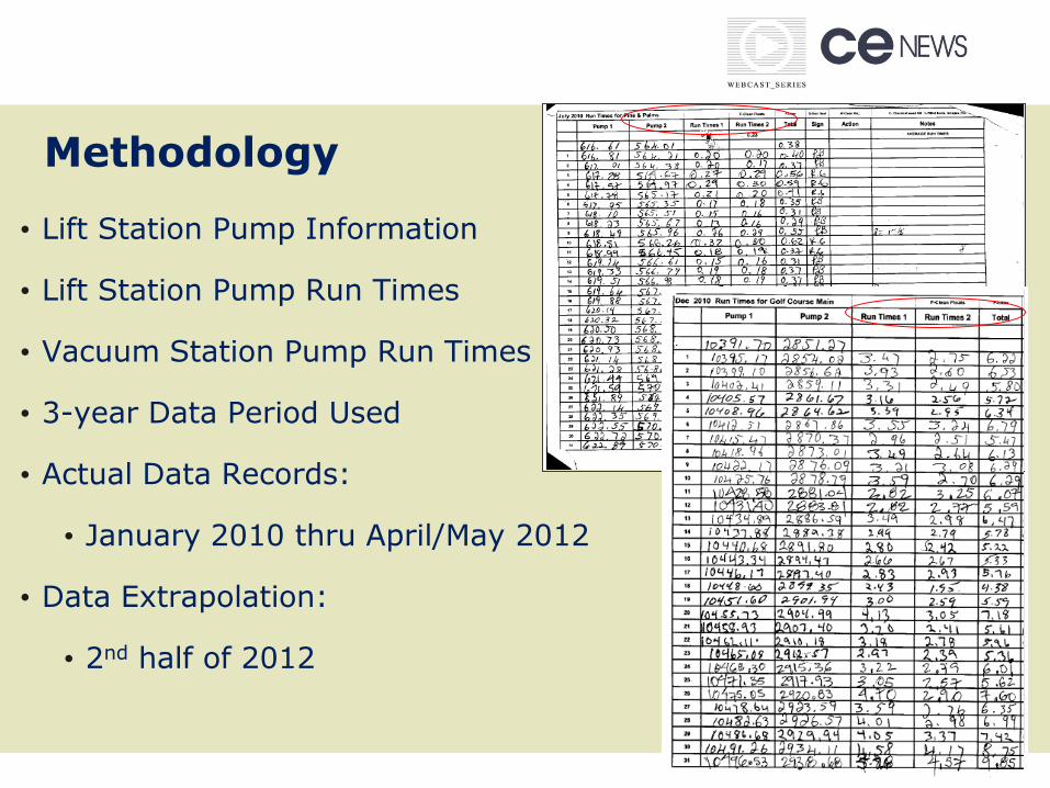
Methodology
• Lift Station Pump Information
• Lift Station Pump Run Times
• Vacuum Station Pump Run Times
• 3-year Data Period Used
• Actual Data Records:
• January 2010 thru April/May 2012
• Data Extrapolation:
• 2nd half of 2012

Typical Power Bill

Lift Station Information • # pumps (duplex, triplex station)
• Voltage
• Full load amperage
• Annualized run times
• Power usage (calculated)
• Power costs (calculated)
• Based on $0.1383 kW/hr costs in the Keys
#
Pumps
Voltage
Pump #1
Amps
Pump
#2
Amps
Total kW
Usage
Annualized
Pump Run
Time (hrs)
Annual
Power
Cost
Monthly
Average
Power
Cost
2 230 22.6 20.8 9.982 5,351 $7,387 $616

Lift Station Layout

Typical KWRU Residential Connections

KWRU System Connections
KWRU Lift Station Name
Equivalent Residential Connections (ERCs)
Laundermat 24
Pines & Palms 24
LS-3 61
Boyd 78
LS-4 80
LS-1 92
LS-2A 121 (298)
ForceMain 160 (240)
GolfCourse 288
TOTAL 928

Lift Station Power Costs

VPS Power Costs

Cost Comparison Results
VPS Power Cost = $11.21/ERC (based on 1,309 ERCs)
L.S. Power Cost = $20.57/ERC (based on 928 ERCs)

Cost Comparison Results
Parameter
WEF MOP No. FD-12
Published Results
KWRU Vacuum Pump
Station
Monthly Power Costs ($/kWh/EDU)
$1.66 - $3.34/EDU
$1.71/EDU
Power Rate $0.10/kWh $0.1383/kWh
Installation Date(s) 1970 – 2001 2002

Results
Stock Island Gravity System
• Multiple small lift stations
w/ only 2 large stations in
the system
• Most gravity systems have
multiple large stations (5-
10)

Results – Stock Island VPS
• Located adjacent to WWTP; meaning less power consumption required for sewage pumps
• Average runtime is 3.28 hrs/day for sewage pumps (Sept 2010)
• Sewage pump flow (VPS) accounted for approx. 162,400 gals of treated flow (approx. 50% of the total system flow – 330,000 gpd through the WWTP)

Conclusions
• Vacuum sewers are more energy efficient when compared with conventional gravity sewer systems for similar service areas
• Results compare favorably with WEF Manual results
• Possible federal and/or state program financial incentives for energy conservation

Acknowledgements
• Chris Johnson, Key West Resort Utilities Corp.
• Bobby Bellino, Key West Resort Utilities Corp.
• Greg Wright, Key West Resort Utilities Corp.
• Rich Naret, P.E., Bilfinger Airvac Water Technologies

Certificate of completion
Live attendees only:
Click on the Certificate button on the console or type the following URL
into your browser. Fill in your name and print your certificate TODAY!
www.cenews.com/webcast/certificate
If you have multiple people at your office viewing this webcast who did not
register, please fill out the Excel document at the URL above and follow the
directions for submittal.
Archive viewers only:
Click on the Quiz/Certificate button or type the following URL into your
browser. You must take an automated quiz on the presentation and
pass it in order to download your certificate of completion.
http://continuingeducation.zweigwhite.com

Q&A

Follow up Q&A
Log on to www.cenews.com/webcast to find answers to more
questions.

Thank you!


![Webcast sponsored by EPA’s Watershed Academy Wednesday ...€¦ · Observed Soil Moisture Changes [1988-2012] 3rd NCA Water Chapter 18 Georgakakos-Fleming Annual surface soil moisture](https://static.fdocuments.in/doc/165x107/5f02af2e7e708231d4057e47/webcast-sponsored-by-epaas-watershed-academy-wednesday-observed-soil-moisture.jpg)