Webasto GPL Service Manual
55
Water heaters Workshop manual NGW 300 LGW 300 GBW 300 NGW 300 / LGW 300 model 02/2006 Identification no. 27 101 03B
-
Upload
vali-chirinciuc -
Category
Documents
-
view
89 -
download
1
description
Webasto GPL Service Manual1585 GPL
Transcript of Webasto GPL Service Manual

Water heaters Workshop manual
NGW 300LGW 300
GBW 300NGW 300 / LGW 300 model
02/2006Identification no. 27 101 03B

NGW 300 / LGW 300 / GBW 300 Table of contents
Table of contents
1 Introduction1.1 Content and purpose ..............................................................................................1011.2 Meaning of the headings in capitals .......................................................................1011.3 Additional documentation to be used .....................................................................1011.4 Safety information and regulations .........................................................................101
1.4.1 General safety regulations ........................................................................1011.5 Legal installation regulations .................................................................................1021.6 Suggestions for improvements and modifications ..................................................102
2 General description 2.1 Combustion air fan .................................................................................................2022.2 Gas pressure regulator ...........................................................................................202
2.2.1 Heating the gas pressure regulator ...........................................................2022.2.2 Delayed-action solenoid (only for the NGW 300) .....................................203
2.3 Heat exchanger ......................................................................................................2032.4 Combustion chamber ............................................................................................2032.5 Control unit .............................................................................................................2032.6 Flame monitor electrode ........................................................................................2032.7 Ignition spark generator with ignition electrodes ....................................................2042.8 Vacuum switch .......................................................................................................2042.9 Gas inlet nozzles ....................................................................................................2042.10 Regulating thermostat ............................................................................................2052.11 Temperature limiter ................................................................................................2052.12 Circulating pump .....................................................................................................205
2.12.1 U 4851 and Aquavent 6000 S (U 4852) circulating pumps ......................205
3 Description of function 3.1 Switching on ...........................................................................................................3013.2 Heating mode ..........................................................................................................3013.3 Switching off ...........................................................................................................3013.4 Fault lockout ...........................................................................................................301
3.4.1 Errors when switching on .........................................................................3013.4.2 Errors during the starting process ............................................................3013.4.3 Errors during the heating mode ................................................................3013.4.4 Shutdown of the heater, if there is low voltage ...............................................3023.4.5 Shutdown of the heater, if there is excessive voltage (not a fault lockout)) ......3023.4.6 Fault lockout, if there is a flame, but the solenoid is deactivated ........................3023.4.7 Errors due to overheating/disruption of the temperature limiter ...........................303
3.5 Removing the heater lock Heizgeräteverriegelung .................................................303
4 Technical data................................................................................................................. 401
I

Table of contents NGW 300 / LGW 300 / GBW 300
5 Troubleshooting and elimination of faults 5.1 General information ................................................................................................5015.2 General fault symptoms ..........................................................................................501
6 Functional tests 6.1 General information ...............................................................................................6016.2 Combustion test ......................................................................................................601
6.2.1 Test of the CO2content ............................................................................6016.3 Tests of individual parts ..........................................................................................602
6.3.1 Test of the regulating thermostat .............................................................6026.3.2 Test of the temperature limiter .................................................................6026.3.3 Test of the ignition electrodes ..................................................................6026.3.4 Test of the flame monitor electrode .........................................................6026.3.5 Test of the ignition spark generator .........................................................6036.3.6 Test of the burner motor ..........................................................................6036.3.7 Test of the vacuum switch .......................................................................6036.3.8 Test of the gas pressure regulator ...........................................................6036.3.9 Test of the delayed-action solenoid in the gas intake pipe ......................604
7 Wiring diagrams7.1 General information ................................................................................................701
8 Service work 8.1 General information ...............................................................................................8018.2 Work on the heater .................................................................................................8018.3 Work on the vehicle ................................................................................................8018.4 Trial run of the heater ............................................................................................8018.5 Maintenance work .................................................................................................801
8.5.1 Disassembly and mounting of the burner head ........................................8028.6 Visual inspections and installation regulations ......................................................802
8.6.1 Connection to the vehicle’s cooling system ..............................................8028.6.2 Connection to the vehicle’s gas system ....................................................8038.6.3 Combustion air supply .............................................................................8038.6.4 Exhaust pipe .............................................................................................803
8.7 Disassembly and installation .................................................................................8058.7.1 Heater: disassembly and installation ....................................................... 8058.7.2 Replacing the temperature limiter .............................................................8058.7.3 Replacing the regulating thermostat ........................................................8058.7.4 Replacing the SG 1585 control unit ..........................................................8058.7.5 Gas pressure regulator: Dismantling and installation ...............................805
8.8 Start-up ...................................................................................................................8068.8.1 Ventilation of the coolant circuit ................................................................806
II

NGW 300 / LGW 300 / GBW 300 Table of contents
9 Repair9.1 General information ...............................................................................................901
9.1.1 Measures for components when the system is disassembled ..................9019.1.2 Implementation of modifications ...............................................................901
9.2 Disasssembly and reassembly ...............................................................................9059.2.1 Replacing the temperature limiter ............................................................9059.2.2 Replacing the regulating thermostat ........................................................9059.2.3 Replacing the SG 1585 control unit .........................................................9069.2.4 Replacing the ignition spark generator ....................................................9069.2.5 Replacing the ignition electrodes .............................................................9079.2.6 Replacing the flame monitor electrode ....................................................9089.2.7 Replacing the burner ................................................................................9089.2.8 Disassembly and reassemmbly of the burner head .................................9089.2.9 Replacing the heat exchanger 9119.2.10 Replacing the combustion chamber .........................................................9119.2.11 Replacing the gas pressure regulator ......................................................9129.2.12 Replacing the delayed-action solenoid in the gas intake line 912
10 Packaging/Storage/Shipping 10.1 General information ..............................................................................................1001
III

NGW 300 / LGW 300 / GBW 300 Table of figures
IV
Table of figures
201 NGW 300 water heater ................................................................................................201
301 Sequence of operation..................................................................................................302
501 General fault symptoms................................................................................................501
601 Setting the CO2-content................................................................................................601602 Testing the electrode clearances..................................................................................602603 Testing the CNG (NGW 300) gas pressure regulator...................................................604604 Testing the LPG (LGW 300) gas pressure regulator ....................................................604
701 Basic wiring for the NGW 300 / LGW 300 / GBW 300 with switch ...............................702702 Basic wiring for the NGW 300 / LGW 300 / GBW 300 with timer .................................703703 System wiring for the GBW 300 - MAN ........................................................................704704 System wiring for the GBW 300 - USA.........................................................................705705 System wiring for the GBW 300 Standard ....................................................................706706 System wiring for the NGW IVECO ..............................................................................707707 System wiring for the LGW / NGW 300 Standard and DC ...........................................708708 System wiring for the NGW 300 EvoBus Citaro ...........................................................709709 System wiring for the NGW 300 MAN ..........................................................................710
801 Disassembly and mounting of the burner head ............................................................802802 Example of a heater installation in a bus ......................................................................804
901 Replacing the SG 1578 control unit by the SG 1585....................................................902902 U 4851 circulating pump...............................................................................................903903 Aquavent 6000 S circulating pump...............................................................................904904 Replacing the temperature limiter and regulating thermostat .......................................905905 Replacing the SG 1585 control unit ..............................................................................906906 Replacing the ignition spark generator .........................................................................906907 Replacing the ignition electrodes, the flame monitor electrode and the burner............907908 Burner head: disassembly and reassembly.................................................................909909 Replacing the heat exchanger and the combustion chamber.......................................911910 Adapters .......................................................................................................................912

NGW 300 / LGW 300 / GBW 300 1 Introduction
1 Introduction
1.1 Content and purpose
This workshop manual serves as support for trained staff in the repair of the NGW 300, LGW 300 und GBW 300 water heaters.
The heaters may only be operated with the kind of gas indicated on the model plate and and with the relevant kind of electrical connection.
1.2 Meaning of the headings in capital letters.
In this manual, the words CAUTION, ATTENTION and PLEASE NOTE have the following meaning:
CAUTIONThis heading is used, if a failure to follow instructions and procedures accurately or to follow instructions and procedures at all can lead to injuries or to fatal accidents.
ATTENTIONThis heading is used, if a failure to follow instructions and procedures accurately or to follow instructions and procedures at all can lead to the damaging of components.
PLEASE NOTEThis heading is used, if attention should be drawn to a specific feature.
1.3 Further documentation to be used
This workshop manual contains all the necessary information and instructions with respect to the repair of the NGW 300, LGW 300 and GBW 300 water heaters. The use of additional documentation can be required.
If necessary, installation and operating instructions can also be used.
1.4 Safety information and regulations
Basically, general accident pevention provisions and the valid industrial safety directions must be adhered to.
"General Safety Regulations" which exceed the framework of these provisions are listed below. The specific safety regulations which affect the present manual are issued in the individual sections or procedures with headings in capital letters.
1.4.1 General safety regulations
"General model approvals " with an official test stamp have been issued by the Kraftfahrt Bundesamt [Federal Bureau of Motor Vehicles and Drivers] for the NGW 300, LGW 300 and GBW 300 water heaters in the area governed by the StVZO [Road Traffic Licensing Regulation]:
~ S 291 for the NGW 300 heater
~ S 313 for the LGW 300 heater
~ S 330 for the GBW heater
and a model approval in accordance with EC Directives 72/245/EEC (EMC) with authorisation no:
e1*72/245*95/54*1260*xx
Liability claims can only be asserted, if the claimant can prove adherence to the the maintenance and safety instructions.
Failure to follow the installation instructions and the directions they contain will result in the exclusion of liability on the part of Spheros. The same shall also apply for repairs which are not conducted by experts or for those where original replacement parts are not used. This will result in the revocation of the general model approval for the heater and thus the general operating permit for the motor vehicle as well.
CAUTION • The heater may not be operated in enclosed spaces
(e.g. a garage or a workshop without an extraction system) due to the danger of contamination and suffocationr, and may not be operated with time preselection.
• Due to the risk of explosion, the heater must be switched off at petrol stations and fuelling tanks.
• Due to fire danger, the heater may not be operated in the vicinity of combustible materials such as dry grass and leaves, paper board, paper, etc.
ATTENTIONWhere combustible vapours or dust can form (e.g. in proximity to fuel, coal, sawdust and grain storage areas or the like), the heater must be switched off.
The heaters must be operated only with the kind of gas indicated on the model plate.
NGW 300 with CNG (natural gas)LGW 300 with LPG (propane)GBW 300 depending on the design with CNG
(natural gas) or LPG (propane)
The proportion of methane in the CNG (natural gas) must amount to 95 % at least. If the proportion of methane is at a still permissible 85-95 %, the CO2value must be readjusted.
Withdrawal of gas in LPG (propane) sysrems must happen in the gas phase.
101

1 Introduction NGW 300 / LGW 300 / GBW 300
ATTENTIONThe gas pressure regulator must be replaced after 4 years of operation, for safety reasons. Failure to do so can lead to leakage and thus an escape of gas, due to aging of the sealing elements.
PLEASE NOTEOil and condensate which have accumulated in the gas pressure regulator must be drained out in accordance with section 8.
CAUTIONAs the combustion noise of the heater is barely audible, special care must be taken when working in the vicinity of the heater. In any event, the heater should be secured to prevent its being switched on unintentionally.
When there is a rather sustained period of smoke emission, unusual combustion noises or a smell of gas, the heater must be put out of operation by removal of the fuse and may only be put back into service after an inspection by staff trained by Spheros.In the area where the heater is the temperature may not exceed 100 °C (storage temperature). If this temperature is exceeded, permanent damage can be done to the electronic system.Checking the status of the coolant should be done in accordance with the process described in documentation provided by car manufacturers. The water in the heater’s heating circuit must contain at least 20 % brand name antifreeze solution. In the event of overheating, if pure water is used, due to its lower boiling point, this can lead to a partial loss of cool water. In this case, coolant must be replenished.Additives in the heating circuit should not adversely affect metal, plastic or rubber and should not form deposits.The opening pressure in a car’s cooling system (normally indicated on the radiator cap) must be between 0.4 and 2 bar of the maximum allowable working pressure.
1.5 Legal regulations for installation
PLEASE NOTEThese regulations are binding in the area subject to the StVZO [Road Traffic Licensing Regulation] and should also be observed in countries where there are no specific provisions.
The installation of heaters must be performed in accordance with installation instructions.
The year in which the heater was first put into operation must be identified by the installer on its model plate by striking out/removing the inapplicable years permanently.
The combustion air must not be taken from the interior of the vehicle.
The opening of the exhaust pipe should be installed to face upwards or to the side, or, if the exhaust pipe runs
under the floor of the vehicle, into the vicinity of the side boundary of the driver’s cab or of the vehicle. Exhaust gas pipes must be laid in such a way as to preclude the expectation of exhaust gas fumes penetrating into the interior of the vehicle. The function of parts of the vehicle which are important for its operation must not be curtailed. Accumulation of condensate in the exhaust pipe absolutely must be removed. If necessary, a condensate drain hole may be drilled.Combustion air intake and exhaust outlet:The openings of the combustion air intake and the exhaust outlet must be designed in such a way as to prevent a sphere with a diameter of 16 mm from passing through.The heater’s electrical lines and switching and control units must be configured so that their flawless operation cannot be restricted under normal conditions.Installing the heater in the driver’s cabin or the passsenger compartment of a bus is not permitted.The heater is not approved for installation in motor vehicles used for the transportation of hazardous materials.Gas pipes must be laid in compliance with the VdTÜV, TRG, ECE-R110. ECE-R67 and DVGW [German Technical and Scientific Association for Gas and Water] guidelines.Gas pipes must be designed in such a way that torsion of the vehicle, engine vibrations and the like have no effect on their durability. They must be protected from mechanical damage.Gas pipes in buses must not be installed in the passenger compartment or the driver’s cab. Parts that convey gas must be configured so that entrances and exits are not in danger of being obstructed in the event of a fire.A regular check of the parts which carry gas, must be carried out annually. Leaky or damaged parts must be replaced by original replacement parts.The particular operating status of the heater (at least on or off) must be easily recogniable.
102

NGW 300 / LGW 300 / GBW 300 2 General description
2 General description
The NGW 300, LGW 300 and GBW 300 water heaters operate in conjunction with the on-board heating system
– to heat the passenger compartment– to defrost the window panels and– to heat the water-cooled engines
in busses.
Water heaters operate independently of the vehicle’s en-gine and are connected to the cooling system, the gas sy-stem and the electrical system of the vehicle.
Heater type:
NGW 300 for the CNG type of gas (natural gas)LGW 300 for the LPG type of gas (propane)
GBW 300NGW 300 version for the CNG type of gas (natural gas)LGW 300 version for the LPG type of gas (propane)
The heater which is designed to work in accordance with the heat exchange principle is controlled by the
regulating thermostat in intermittent operation
The heater basically consists of
– the burner head– the heat exchanger and– the combustion chamber zusammen
The following components are located in the heater:
– a control unit– a flame monitor electrode– an ignition spark generator with ignition electrodes– a regulating thermostat– a temperature limiter and– a vacuum switchimfor control and monitoring.
In addition, a circulating pump and a gas pressure regula-tor for the gas are installed in the vehicle to supply the hea-ting system as well as a thermostat valve for heating the gas pressure regulator. The NGW 300 also has a time-delayed solenoid installed in the heater’s gas suction hose.
Fig. 201 NGW 300 water heater
1 Burner head 2 Coolant inlet 3 Temperature limiter 4 Regulating thermostat 5 Coolant outlet 6 Heat exchanger 7 Exhaust fume outlet 8 Gas inlet 9 Differential pressure connection10 Combustion air intake11 Ignition spark generator12 Control unit
34
5
6
7
8
91011
12
1
2
201

2 General description NGW 300 / LGW 300 / GBW 300
2.1 Combustion air fan
The combustion air fan forces the air necessary for com-bustion from the combustion air inlet into the combustion chamber. In addition, the necessary amount of gas is aspi-rated from the fan by means of the gas pressure regulator.
The fan comprises an impellent and a rotor which are joi-ned together by means of a coupling. The air is sucked in via a protective grille in the hood and mixed with gas in the mixer.
There is a special version for a combustion air intake ex-tension which commits the combustion air to be taken in by means of this extension.
2.2 Gas pressure regulator
Gas is supplied by means of the vehicle’s gas supply sy-stem, in which the gas pressure regulator is incorporated. Different types of regulators are utilised for operation with CNG (natural gas) and LPG (propane).
In CNG gas pressure regulators, the gas pressure of the system is regulated downward from a maximum of 220 bar of excess pressure in 3 steps to barely below at-mospheric pressure. A safety valve protects the gas pres-sure regulator in the event of a pressure surge.
In LPG gas pressure regulators, the gas pressure of the system is regulated downward from a maximum of 30 bar of excess pressure in 2 steps to barely below atmosphe-ric pressure.
After the solenoids have opened, the required quantity of gas is sucked out of the gas pressure regulator by the combustion air fan through the gas suction hose. The re-quired quantity of gas is released by a diaphragm valve in the gas pressure regulator. This is dependent on the cross-section of the gas intake nozzle and the negative pressure in the gas suction pipe.
CNG gas pressure regulator (NGW 300)
LPG gas pressure regulator (LGW 300)
2.2.1 Heating the gas pressure regulator
As the expansion of the compressed gas causes considera-ble cooling, the gas pressure regulator must be warmed up. This is accomplished by integration into the cool water cir-cuit. The flow rate is regulated by a thermostat valve.
At approximately 50 °C, the thermostat valve begins to re-strict the flow rate and is in the final position at approxima-tely 60°C. Further heating and regulation of the flow rate are guaranteed by a leakage amount.
1 Gas outlet to the heater2 Drain plug (oil)3 Water inlet4 Solenoid (2)5 Gas inlet from the storage tank6 Water outlet
4
4
5
3
6 1
2
1 Gas outlet to the heater2 Solenoid (2)3 Water outlet4 Drain plug (oil)5 Water inlet6 Safety valve7 Gas inlet from the storage tank
2
27
65 3
1
4
202

NGW 300 / LGW 300 / GBW 300 2 General description
Thermostat valve
2.2.2 Delayed-action solenoid (only for the NGW 300)
The delayed-action solenoid is necessary at gas supply pressures of 8 bar for the safe functioning of the input so-lenoid valve on the gas pressure regulator.The solenoid is installed in the gas hose from the gas pres-sure regulator to the heater and is connected electrically in series to the solenoids in the gas pressure regulator.After the solenoids in the gas pressure regulator are ope-ned, the delayed-action solenoid releases the gas flow to the heater with a second’s delay.For higher gas supply pressures, the delayed-action sole-noid can be installed as an additional safety element. The delayed-action solenoid is a basic integral part of the GBW 300, version NGW.
Delayed-action solenoid
2.3 Heat exchangerIn the heat exchanger, the heat produced by combustion is transferred to the coolant circuit.
2.4 Combustion chamberThe gas-air mixture is distributed in the combustion cham-ber and is burned there. The heat exchanger and the coo-lant flowing through it are heated by this process.
2.5 Control unit
The control unit guarantees the function sequence and monitoring of the firing operation.The SG 1578 control unit for the NGW 300 and LGW 300 heaters is no longer available and is being replaced by the modified SG 1585 control unit. When refitting, the appropriate vehicle-specific adapter wiring harness is required.The GBW 300 heaters are already equipped with the SG 1585 control unit.
2.6 Flame monitor electrode
During the entire firing operation, the state of the flame is monitored by the flame monitor electrode. By means of io-nisation of the air, depending on the temperature (flame), the signal is changed at the flame monitor electrode and processed by the control unit.
0-90°0-90° 0-90°0-90°
SG 1578
SG 1585
Flame monitor electrode
Ignition electrodes
203
2 General description NGW 300 / LGW 300 / GBW 300
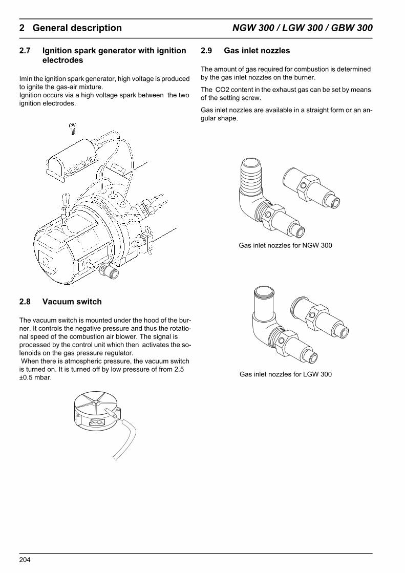
2.7 Ignition spark generator with ignition electrodes
ImIn the ignition spark generator, high voltage is produced to ignite the gas-air mixture. Ignition occurs via a high voltage spark between the two ignition electrodes.
2.8 Vacuum switch
The vacuum switch is mounted under the hood of the bur-ner. It controls the negative pressure and thus the rotatio-nal speed of the combustion air blower. The signal is processed by the control unit which then activates the so-lenoids on the gas pressure regulator. When there is atmospheric pressure, the vacuum switch is turned on. It is turned off by low pressure of from 2.5 ±0.5 mbar.
2.9 Gas inlet nozzles
The amount of gas required for combustion is determined by the gas inlet nozzles on the burner.
The CO2 content in the exhaust gas can be set by means of the setting screw.
Gas inlet nozzles are available in a straight form or an an-gular shape.
Gas inlet nozzles for NGW 300
Gas inlet nozzles for LGW 300
204

NGW 300 / LGW 300 / GBW 300 2 General description
2.10 Regulating thermostat
The regulating thermostat (bimetal) measures the coolant temperature at the water outlet of the heat exchanger. The signal is conducted to the control unit and is processed there.The system is switched off at 75±3°C and is switched on again at 68±5°C.
2.11 Temperature limiter
The temperature limiter (bimetal) protects the heater against incorrect high temperatures. The temperature li-miter acts at a temperature above 125°C and switches off the heater. The temperature limiter may be reset mechanically, once a temperature of 90 °C has been reached.
2.12 Circulating pump
The circulating pump which is located externally guaran-tees that the coolant is conveyed in the vehicle’s or the heater’s circuit.The circulating pump is switched on by the control unit and runs throughout the entire operation of the heater.
The heater can be operated with the U4814, the U4851 or the Aquavent 6000 S (U 4852) circulating pump.
2.12.1 The U 4851 and Aquavent 6000 S (U 4852) circulating pumps
The U 4851 / Aquavent 6000 S (U 4852) circulating pump is equipped with a brushless motor.
Soft startThe motor starts slowly and protects its material from wear. It reaches its maximum speed only after approx. 5 seconds.
Protection against dry runningA dry running protection system is integrated into the mo-tor for speeds of 3,300 rpm.
If the motor consumes less than 4 A of current in a timef-rame of 1018 revolutions, it detects that it is running dry. The motor is switched off when it goes into error mode (af-ter approx. 10 seconds of operation or approx. 15 secon-ds after being switched on.
For the Aquavent 6000 S circulating pump (U 4852) the permitted dry running was extended to 45 minutes.
Blocking protectionIf the operating speed falls below 57 rpm, the motor is switched off by the error mode after approx. 1 second.
If the motor fails to complete a revolution in 1 second, de-spite having a current feed , it is switched off by the error mode.
Temperature limiter
Regulating thermostat
U 4851
Aquavent 6000 S(U 4852)
U 4814
205

2 General description NGW 300 / LGW 300 / GBW 300
Overload protectionOverload protection is activated after completion of the soft start. In this way, the consumption of current is restric-ted and the speed is regulated to 5,550 rpm. This means that the motor will not be damaged, by the hydraulic com-pression of the circulating pump.
Error modeThe motor is switched off by the error mode in the event of faults. After approx. 5 seconds, the motor will be swit-ched from error mode into the power-saving sleep mode.
Sleep modeIn sleep mode, the internal users of the motor’s electronic system are switched off. The consumption of current in this mode then amounts to < 2 mA.
Reactivation of the motorThe motor can be reactivated from sleep mode. This is done by disconnecting it from the power supply for ap-prox. 2 minutes. After the voltage supply is restored, the motor will restart in soft start.
Reverse polarity protectionThe motor is not equipped with internal reverse polari-ty protection. The wiring harness in conjunction with a15A fuse protect the motor against reverse polarity.
206

NGW 300 / LGW 300 / GBW 300 3 Description of function
3 Description of function
Depending on how it is equipped, the heater is turned on and off by a switch, a timer or the airconditioning control unit.
An operating indicator light is available to monitor the opearting procedure.
After the heater is switched off ,there is an after-run.(see 3.3 "Switching off".
NOTE.Below is a description of of the operation cycle with the SG 1585 control unit.
3.1 Switching on
When the heater is switched on, the operating indicator lights up. The combustion air fan and the circulating pump start.
The vacuum switch is shut off at the proper motor speed (low pressure) and the signal is transferred to the control unit and processed.
After approx. 15 seconds, the high voltage ignition spark begins. If there is a shortlived drop in voltage when the heater is switched on in the low voltage range, the lead time is extended.
One second later, the solenoids open in the gas pressure regulator (after another second, the delayed-action solenoid in the gas hose for the NGW 300 opens, if available) and the gas-air mixture is conveyed into the burner by means of the combustion air fan, where it is ignited by high voltage ignition sparks.
At the beginning of the flame monitoring, the ignition spark generator is shut down so that flame detection is not disrupted.
3.2 When the heater is in operation
Once the operating temperature has been reached, the control unit takes over the regulated operation, whereby the temperature of the heat exchanger (cooling liquid) is maintained at a virtually constant level by alternately switching it on and off.
If the temperature rises above the upper switching point of the regulating thermostat, the solenoids in the gas pressure regulator close off the gas supply and the after-run is initiated.
The flame is extinguished, but the combustion air fan and the circulating pump continue to run.
The circulating pump remains in operation during the control pause; the operating indicator lights up.
If the temperature falls to the lower switching point of the regulating thermostat, the heater will be started again and the after-run will be ended.
3.3 Switching off
When the heater is switched off, the solenoids in the gas pressure regulator are closed and combustion ends. The operating indicator light goes out and the after-run begins. The combustion air fan and the circulating pump will be switched off after approx. 125 seconds.
Switching the heater on again during the after-run is permissible. It will restart only after the after-run has ended.
3.4 Fault lock-out
Upon detection of one of the fault characteristics listed below, the heater performs a fault lock-out whereby the operating indicator light goes out. The combustion air fan and the circulating pump will be switched off after 125 seconds.
3.4.1 Faults when the heater is switched on
– Interruption of the temperature limiter– Short circuit of the vacuum switch– Short circuit of the fan motor– Short circuit of the circulating pump (when
programmed)– Interruption of the circulating pump (when
programmed) – Short circuit /interruption of the flame monitor mode – Short circuit of the ignition spark generator
3.4.2 Faults during the starting process
– Intrerruption of the vacuum switch– Interruption of the temperature limiter– Solenoid valves don’t open– Ignition spark generator defect– Flame monitor electrode defect– Flame detected in the supply line– No flame detected after approx. 25 seconds
3.4.3 Faults while the heater is in operation
– Failure to reach the low voltage threshold of < 21.5 V for a duration of 20 seconds
– Interruption of combustion for longer than 10 seconds– Short circuit /interruption of the flame montor
electrode during combustion – Interruption of the temperature limiter during
combustion – Short circuit / interruption of the solenoid during
combustion
301
3 Description of function NGW 300 / LGW 300 / GBW 300
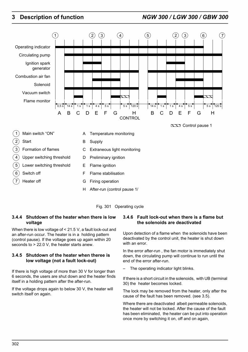
Fig. 301 Operating cycle
3.4.4 Shutdown of the heater when there is low voltage
When there is low voltage of < 21.5 V, a fault lock-out and an after-run occur. The heater is in a holding pattern (control pause). If the voltage goes up again within 20 seconds to > 22.0 V, the heater starts anew.
3.4.5 Shutdown of the heater when theree is low voltage (not a fault lock-out)
If there is high voltage of more than 30 V for longer than 6 seconds, the users are shut down and the heater finds itself in a holding pattern after the after-run.
If the voltage drops again to below 30 V, the heater will switch itself on again.
3.4.6 Fault lock-out when there is a flame but the solenoids are deactivated
Upon detection of a flame when the solenoids have been deactivated by the control unit, the heater is shut down with an error.
In the error after-run , the fan motor is immediately shut down, the circulating pump will continue to run until the end of the error after-run.
– The operating indicator light blinks.
If there is a short circuit in the solenoids, with UB (terminal 30) the heater becomes locked.
The lock may be removed from the heater, only after the cause of the fault has been removed. (see 3.5).
Where there are deactivated albeit permeable solenoids, the heater will not be locked. After the cause of the fault has been eliminated, the heater can be put into operation once more by switching it on, off and on again,
Operating indicator
Circulating pump
Ignition sparkgenerator
Combustion air fan
Solenoid
Vacuum switch
Flame monitor
1 Main switch “ON”
2 Start
3 Formation of flames
4 Upper switching threshold
5 Lower switching threshold
6 Switch off
7 Heater off
A Temperature monitoring
B Supply
C Extraneous light monitoring
D Preliminary ignition
E Flame ignition
F Flame stabilisation
G Firing operation
H After-run (control pause 1/
CONTROL
Control pause 1
302

NGW 300 / LGW 300 / GBW 300 3 Description of function
3.4.7 Faults due to overheating /interruption of the temperature limiter
If the heater overheats there is a fault lock-out by means of the temperature limiter and the heater becomes locked after the error after-run.
After the system has cooled down and the cause has been eliminated and the heater has been examined for possible damage, in particular to the cabling, the temperature limiter and the regulating thermostat, the head of the temperature limiter must be reset manually.
Only then can the lock be removed from the heater.
3.5 Removing the heater lock
The heater lock must be removed as follows:
• By means of diagnosis: delete fault memoryor
• Switch on the heater; in the error after-run, remove the heater from the power supply for 5 seconds (pull the fuse). Restore the power supply and start the heater again.
303

3 Description of function NGW 300 / LGW 300 / GBW 300
Blank page for notes
304

NGW 300 / LGW 300 / GBW 300 4 Technical data
4 Technical data
As long as no limit values are indicated, the technical data refer to the customary heater tolerances of ± 10% at an ambient temperature of + 20°C and at nominal voltage.
Type of gas:The heaters may only be operated with the kind of gas in-dicated on the model plate.
PLEASE NOTEThe NGW 300 version of the heaters is set for CNG-Gas with a methane content of more than 95% by volume when it leaves the factory. If the methane content is below 95% by volume (85 -95% by volume), the CO2 content in the exhaust must be reset.
Electrical components:Control units, the motor for the combustion air blower, the circulating pump, gas pressure regulator solenoids, the delayed-action solenoid, ignition spark generators and pre-selector/timer are designed for 24 V.
Components such as the temperature limiters, regulating thermostats, ignition electrodes, flame monitor electro-des, vacuum switches and switches are not designed for a specific voltage.
PLEASE NOTEThe allocation of circulating pumps to heaters must be done in accordance with the cold water side resistors.
Heater model GBW 300Test mark ~ S 330Version NGW 300 LGW 300Heat flow 30 kW 30 kWFuel CNG
(natural gas with a minimum of 95 % methane)
LPG (Propan)
Combustion gas pressure when entering the heater - 2,5 mbar - 2,5 mbarFuel consumption 3,8 m3/h (3,15 kg/h) (2,9 kg/h)Nominal voltage 24 Volt 24 VoltOperating voltage range 21 ... 30 Volt 21 ... 30 VoltRated power consumption without a circulating pump 110 W 100 WPressure regulator used Landi Renzo, TN 1, 24V Landi Renzo, SE 81, 24VPressure at the pressure regulator intake max/min 220 bar / 8 bar 30 bar / 1,5 barPermissible ambient temperature for the heater, control unit and pressure regulator in the engine com-partment
Storage temperature -25...+ 100 °COperating temperature-25...+85 °C
Storage temperature-20... + 100 °COperating temperature-20...+ 85°C
Permissible ambient temperature for the heater,control unit and pressure regulator in the installation box
Storage temperature- 25 ... + 85 °COperating temperature-25...+ 60°C
Storage temperature- 20 ... + 85 °COperating temperature-20...+ 60°C
Permissible operating overpressure 0,4 ... 2,0 bar 0,4 ... 2,0 barHeat exchanger filling capacity 1,8 l 1,8 lMinimum capacity of the circuit system 10,0 l 10,0 lCO2 in exhaust gas at nominal voltage 8.5 ... 10.5% by volume 10 ... 12 Vol %Thermostat regulating range Switches off above 75 ± 3 °C
Switches on above 68 ± 3 °CSwitches off above 75 ± 3 °CSwitches on above 68 ± 3 °C
Heater dimensions(Tolerance ± 3 mm)
L 620 mmB 246 mmH 220 mm
L 620 mmB 246 mmH 220 mm
Weight: heaterpressure regulator
20 kg3,2 kg
20 kg2,0 kg
Circulating pump U 4814 Aquavent 6000 SSupply rate 5200 (against 0,15 bar) 6000 (against 0,4 bar)Nominal voltage 24 Volt 24 VoltOperating voltage range 20...28 Volt 18...32 VoltRated power consumption 104 W 215WDimensions(Tolerance ± 3 mm)
L 228,5 mmB 100 mmH 105 mm
L 284 mmB 115 mmH 110 mm
Weight 2,1 kg 2,95 kg
401

4 Technical data NGW 300 / LGW 300 / GBW 300
Blank page for notes
402

NGW 300 / LGW 300 / GBW 300 5 Troubleshooting and elimination of faults
5 Troubleshooting and eliminationof faults
5.1 General information
This section describes the troubleshooting and the elimi-nation of faults in NGW 300 / LGW 300 and GBW 300 heaters.
ATTENTIONTroubleshooting and the elimination of faults require pre-cise knowledge about the structure and the function of the individual heater components and may only be carried out by expert staff.
If there is any doubt, you can find out how the components function in relationship to one another by reading sections 2 and 3.
ATTENTIONNormally, fault detection is limited to locating the faulty components.The following causes of faults are not taken into conside-ration and should be thoroughly checked and/or a fault for this reason should be excluded:
Corrosion of connectorsA loose connection on a plugCrimping faults on connectorsCorrosion of pipes and fusesCorrosion of the battery poles
After the elimination of each fault, a functional test must be conducted in the vehicle.
5.2 General fault symptoms
The following table (fig. 501) lists the possible, general fault symptoms.
Fig. 501 General fault symptoms (page 1 of 2)
Fault symptom possible cause
Electrical faults
The operating indicator light does not go on and the hea-ter fails to function.
• Inadequate voltage supply• Defective fuses• The line to the plugs of the control unit’s X2 connec-
tion is interrupted
The F1 fuse is activated. • Short circuit in the circulating pump or in the supply line to the heater
• Short circuit in the supply line to the heater/ motor
• A defective operating indicator light or wiring to the operating indicator light is interrupted or. shortcircuited
Faults in the water system
The heater ceases to function correctly, because the connected heat exchangers are not delivering adequate heat.
The flow rate is too low, because• there is air in the heater, in the heat exchangers or in
segments of the system• cocks (flow rate regulators) are restricted, dirty or
closed• there are impurities in the system, e.g. in narrow places• of the inadequate delivery rate of the circulating pump
(air in the pump housing),Inverted rotational direction – check the(cable colours(black + / brown –) Inadequate anti-freeze protection,The system resistance is excessive (particularly high when cold)
501

5 Troubleshooting and elimination of faults NGW 300 / LGW 300 / GBW 300
Fig. 501 General fault symptoms (page 2 of 2)
Fault symptom possible cause
• Circulating pump defect
Heat exchangers (water/air) supply has too little heat, because • there is air in the heat exchangers or in the system
sections• the heat exchange (internal/external) surfaces are
dirty• the air intake or output is inadequate • the blower has: an inadequate delivery rate / an in-
correct rotation direction / excessive resistance• the proportion of antifreeze agent is too high • the dimensions of the heat exchanger are too small
Rough estimate of the flow rate
Flow rate in [l/h] =
Heat supply [kW] according to model plate
Temperature difference Δt in [K] or [°C]between the water input and output, measured at the heater (e.g. with a contact thermometer)
x 860
Faults in the gas supply
No fuel supply to the heater • empty gas tank• bent, closed, clogged or leaky lines• frozen water inlets in the gas regulator or in the
gas line• contaminated gas filters in the gas filter regulators• closed gas supply valve• solenoids don’t open• defective gas pressure regulator • defective vacuum switch• defective delayed-action solenoid
Faults in combustion • the speed of the combustion air fan is too low• defective combustion air fan• restricted combustion air supply• restricted gas supply• the methane content of the gas doesn’t match requi-
rements (min. 95% by volume)• contaminated combustion air intake grille
502

NGW 300 / LGW 300 / GBW 300 6 Functional tests
6 Function tests
6.1 General information
This section decribes the tests on heaters in both their installed and dismounted states to prove that they are operating properly.
CAUTIONHeaters should not be operated in closed spaces such as garages or workshops without an exhaust system.
Due to the danger of fire, do not switch on the heater if the burner head is dismantled.
6.2 Combustion test
6.2.1 Test of CO2content
The CO2content in the exhaust gas must be measured:
– as part of a function test– if there are irregularities in combustion– after the burner has been repaired– after the gas pressure regulator has been replaced– when refitting the delayed-action solenoid in the NGW
300 heater– when retrofitting NGW 300 and LGW 300 heaters with
an adjustable nozzle – for the operation of the NGW 300 heater with CNG
(natural gas) whose methane content is below 95 % by volume
– after the installation of a replacement burner
PLEASE NOTEThe CO2values for the NGW 300 replacement burner are set at the factory for utilisation with the delayed-action solenoid.
The CO2-content must be in the following range:
The NGW 300 heater and the GBW 300 heater in the NGW 300 version 8.5 to 10.5 % by volume
The LGW 300 heater and the GBW 300 heater in the LGW 300 version 10.0 to 12.0 % by volume
PLEASE NOTE In heaters that have not yet been equipped with a gas intake nozzle, no adjustment of the CO2-setting is possible. These heaters should be retrofitted with the adjustable gas inlet nozzle, in order to set the CO2value correctly.
For heaters which are already equipped with the adjustable gas inlet nozzle the CO2content can be set at the setting screw (Fig.. 601).
The following tool is needed for this:
• NGW 300 a 6 mm Allen key• LGW 300 a 4 mm Allen key
Fig. 601 Setting the CO2-content
Setting screw
CO2
PLEASE NOTE When setting the CO2, turn the setting screw carefully, as even a slight turn will have a strong effect on the CO2-value.
601

6 Functional tests NGW 300 / LGW 300 / GBW 300
6.3 Tests of individual components
6.3.1 Test of the regulating thermostat
PLEASE NOTEThe regulating thermostat must be firmly screwed in (by hand) and the protective cap must be mounted. The cables must not be damaged.
TestDuring the test with a digital multimeter the the flow rate of the regulating thermostat should be checked.
Switching temperature:
– opens at 75 ± 3 °C– closes at 68 ± 5 °C
At room temperature the contact is closed. When it heats to above the upper switching point, it is opened.
6.3.2 Temperature limiter test
ATTENTIONThe retaining spring must be in the temperature limiter’s slot and must be locked in place on both sides of the housing. Union. The cables must not be damaged and must not be located above the release button.
Test During the test with a digital multimeter the the flow rate of the regulating thermostat should be checked.
Switching temperature:
– opens at 125 °C +8 /-4 °C
When it cools down, the temperature limiter remains open until approx. 5 °C. Once it reaches a temperature below 90 °C, it can be reset by pressing the button.
6.3.3 Test of the ignition electrodes
PLEASE NOTEThe insulating material of the ignition electrodes must not show any sign of damage or cracks. Ignition electrodes with an electrode clearance outside of the tolerance or ignition electrodes which are not working flawlessly must be replaced
Test– Examine the insulation material of the ignition
electrodes for damage.– Check the electrode clearance in accordance with
figure. 602 and the condition of the ignition electrodes.
6.3.4 Test of the flame monitor electrode
PLEASE NOTE The insulating material of the ignition electrodes must not show any sign of damage or cracks. If a flame monitor electrode is not working perfectly, it should be replaced.
Test– Examine the insulating material of the flame monitor
electrode for damage.– Check the electrode clearance in accordance with
fig. 602 and the status of the flame monitor electrode.
Fig. 602 Testing the electrode clearances
11,4
±1
5 ±0
,513
,4 ±
1
602

NGW 300 / LGW 300 / GBW 300 6 Functional tests
6.3.5 Testing the ignition spark generator
CAUTIONHigh voltage! On the ignition electrodes, a voltage of approx. 8,000 V arcs over.
ATTENTIONDo not supply voltage to the ignition spark generator without ignition electrodes.
PLEASE NOTEDamaged sleeves or sleeves which were not pushed up far enough to seal the ignition electrodes will lead to arc-over here when there is moisture (condensation) present
Test– Use direct current voltage of 24 V (positive on the
black line; negative on the brown line).– Target status: ignition sparks on the ignition
electrodes jump over.
6.3.6 Test of the burner motor
PLEASE NOTETesting of the combustion air motor is conducted when it is installed. If the target values are not achieved, the motor is replaced.
Test– Examine the motor for the quality of its bearings
(sluggishness) – Measure the rpm
Target rpm at 24 V: 5800 ± 580 min-1
6.3.7 Vacuum switch test
Test– Check plug contacts for corrosion and to make sure
that they are firmly attached.– Examine the general condition of the hose to the gas
mixer and check for damage.– Examine the vacuum switch’s housing for cracks or
other damage.– Examination of the switching function
Target values: The vacuum switch is open without low pressure. The vacuum switch must be shut when the low pressure is 2.5 ± 0.5 mbar.
6.3.8 Gas pressure regulator test
ATTENTIONThe gas pressure regulator must not be disassembled.
PLEASE NOTETesting is done when the heater is installed.
6.3.8.1 General test
– Testing plug contacts for corrosion and to make sure that they are firmly attached.
– Was the gas pressure regulator replaced after 4 years of operation?
– When the heater is switched off, no gas may escape through the outlet to the heater or when solenoids are open.
– The supply line connection must be checked for impermeability
6.3.8.2 Test of the intake valve on the gas pressure regulator
During the firing operation, disconnect the plug connection to the inlet valve, The enrichment valve and the delayed-action solenoid in the gas intake pipe (in the NGW 300) must still be controlled Combustion must stop immediately.If combustion doesn’t stop immediately, the gas pressure regulator must be replaced.
6.3.8.3 Examination of the functioning of the enrichment valve on the gas pressure regulator
During the firing operation and under hot running conditions, disconnect the plug connection to the enrichment valve. The CO2-content of the exhaust gas must drop considerably (1,5 - 3 %).If the CO2doesn’t change, the gas pressure regulator must be replaced.
6.3.8.4 Testing the safety valve on the gas pressure regulator
If the intake valve is open (applicable to CNG gas pressure regulators, only), no gas must escape at the safety valve’s hose connection. If gas escapes, the gas pressure regulator must be replaced.
603

6 Functional tests NGW 300 / LGW 300 / GBW 300
6.3.8.5 Checking for accumulations of oil and condensation in the gas pressure regulator
Possible accumulations of oil and condensate must be drained by unscrewing the drain plug on the gas pressure regulator. If larger amounts have accumulated, testing must be done to establish whether the quarterly draining interval was adhered to. If the result is positive, the interval must be shortened.In the event that solid particulate matter is found in the oil/condensate, the gas pressure regulator must be replaced.After the test, the drain plug for the CNG (NGW 300) gas pressure regulator must be screwed in with a tightening torque of 8 ±1 Nm. The drain plug for the LPG (LGW 300) gas pressure regulator must be handscrewed.
PLEASE NOTE• For installed gas pressure regulator equipment with
an overhead drain plug, the oil/condensate can be drained by means of the gas outlet of the gas pressure regulator (1, fig. 603 u. 604). To accomplish this, dismount the gas hose from the gas pressure regulator and drain the oil/condensate out of the gas pressure regulator and the gas hose.
• If the gas pressure regulator’s connection port is not accessible, then the oil/condensate can be drained by dismounting the gas hose at the heater or via the gas hose at the inlet of the delayed-action solenoid. Therefore, the gas hose must be directed downwards.
• Finally, reconnect the gas hose and secure with hose clamps.
Fig. 603 CNG (NGW 300) Gas pressure regulator test
Fig. 604 LPG (LGW 300) Gas pressure regulator test
6.3.9 Test of the delayed-action solenoid in the gas intake pipe
Test– Use 24 V direct current voltage.
Target state: the solenoid must open after a delay of 1 second.If the time is exceeded or undershot by 0.5 seconds, the delayed–action solenoid must be replaced.
1 Gas outlet to the heater2 Enrichment valve3 Water outlet4 Drain plug (oil)5 Water inlet6 Safety valve7 Gas inlet from the storage tank8 Intake valve
8
27
6
5 3
1
4
1 Gas outlet to the heater2 Drain plug (oil)3 Water inlet4 Enrichment valve5 Gas inlet from the storage tank6 Intake valve7 Water outlet
6
4
5
3
7 1
2
604
NGW 300 / LGW 300 / GBW 300 7 Wiring diagrams
7 Wiring diagrams
7.1 General information
Figures. 701 to 709 show the system wiring diagrams of the heaters with switches and/or timers and vehicle-spe-cific circuits.
701

7 Wiring diagrams NGW 300 / LGW 300 / GBW 300
Fig. 701 Basic wiring for the NGW 300 / LGW 300 / GBW 300 with a timer
1 Interface for vehicle plug connection,(customised)
2 W-Bus diagnosis
3 Not required for the USA/Canada
4 USA/Kanada
Item Designation CommentA1 Heater NGW 300 / LGW 300A2 Conrol unitB1 Temperature limiterB2 Regulating thermostatF1 25 A fuse DIN 72581F2 5 A fuse DIN 72581H1 Lights Operating indicatorH2 Lights Flame indicatorK1 Solenoid High pressureK2 Solenoid Low pressureK3 Solenoid
(1 sec.delayed action)only for the NGW
M1 Motor Circulating pumpM2 Motor Combustion air fanS1 ON/OFF switch HeaterS2 ON/OFF switch Remote-controlled circulating pumpS3 Vacuum switch
Item Designation CommentU2 Ignition electrodeU3 Flame monitor electrodeX1 2-pin plug connection A2 control unitX2 4-pin plug connection A2 control unitX3 8-pin plug connection A2 control unitX4 4-pin plug connection A2 control unitX5 4-pin plug connection A2 control unitX6 2-pin plug connection Pressure regulatorX7 2-pin plug connection Delayed-action solenoidX8 2-pin plug connection Temperature limiterX9 2-pin plug connection Regulating thermostatX10 1-pin plug connection Ignition spark generatorX11 1-pin plug connection Vacuum switchX12 1-pin plug connection Combustion air fanX13 1-pin plug connection Flame semsorX14 2-pin plug connection Circulating pump
702

NGW 300 / LGW 300 / GBW 300 7 Wiring diagrams
Abb. 702 Basisschaltung für NGW 300 / LGW 300 / GBW 300 mit Vorwahluhr
Item Designation CommentA1 Heater NGW 300 / LGW 300A2 Conrol unitB1 Temperature limiterB2 Regulating thermostatF1 25 A fuse DIN 72581F2 5 A fuse DIN 72581H2 Lights Flame indicatorK1 Solenoid High pressureK2 Solenoid Low pressureK3 Solenoid
(1 sec.delayed action)only for the NGW
M1 Motor Circulating pumpM2 Motor Combustion air fanP TimerS2 ON/OFF switch Remote-controlled circulating pumpS3 Vacuum switch
Item Designation CommentU2 Ignition electrodeU3 Flame monitor electrodeX1 2-pin plug connection A2 control unitX2 4-pin plug connection A2 control unitX3 8-pin plug connection A2 control unitX4 4-pin plug connection A2 control unitX5 4-pin plug connection A2 control unitX6 2-pin plug connection Pressure regulatorX7 2-pin plug connection Delayed-action solenoidX8 2-pin plug connection Temperature limiterX9 2-pin plug connection Regulating thermostatX10 1-pin plug connection Ignition spark generatorX11 1-pin plug connection Vacuum switchX12 1-pin plug connection Combustion air fanX13 1-pin plug connection Flame semsor
1 Interface for vehicle plug connection (customised)
2 W-Bus diagnosis
3 Not required in the USA/Canada
4 USA/Canada
703

7 Wiring diagrams NGW 300 / LGW 300 / GBW 300
Fig. 703 System wiring for the GBW 300 - MAN
1 Reglator control outlet
2 W-Bus diagnosis
Item Designation CommentA1 Heater GBW 300A2 Conrol unitB1 Temperature limiterB2 Regulating thermostatF1 25 A fuse DIN 72581F2 5 A fuse DIN 72581H1 Lights Operating indicatorH2 Lights Flame indicatorK1 Solenoid High pressureK2 Solenoid Low pressureK3 Solenoid
(1 sec.delayed action)only for the NGW
M1 Motor Circulating pumpM2 Motor Combustion air fanS1 ON/OFF switch HeaterS2 ON/OFF switch Remote-controlled circulating pumpS3 Vacuum switchU1 Ignition spark generator
Item Designation CommentU2 Ignition electrodeU3 Flame monitor electrodeX1 2-pin plug connection A2 control unitX2 4-pin plug connection A2 control unitX3 8-pin plug connection A2 control unitX4 4-pin plug connection A2 control unitX5 4-pin plug connection A2 control unitX6 2-pin plug connection Pressure regulatorX7 2-pin plug connection Delayed-action solenoidX8 2-pin plug connection Temperature limiterX9 2-pin plug connection Regulating thermostatX10 1-pin plug connection Ignition spark generatorX11 1-pin plug connection Vacuum switchX12 1-pin plug connection Combustion air fanX13 1-pin plug connection Flame sensorX14 2-pin plug connection Circulating pumpX15 5-pin plug connection Vehicle interfaceX16 8-pin plug connection Vehicle interfaceY Pressure regulator
704

NGW 300 / LGW 300 / GBW 300 7 Wiring diagrams
Fig. 704 System wiring for the GBW 300 - USA
1 W-Bus diagnosis
Item Designation CommentA1 Heater GBW 300A2 Control unitB1 Temperature limiterB2 Regulating thermostatF1 25 A fuse DIN 72581F2 5 A fuse DIN 72581H1 Lights Operating indicatorH2 Lights Flame indicatorK1 Solenoid High pressureK2 Solenoid Low pressureK3 Solenoid
(1 sec.delayed action)only for the NGW
M1 Motor Circulating pumpM2 Motor Combustion air fanS1 ON/OFF switch HeaterS2 ON/OFF switch Remote-controlled circulating pumpS3 Vacuum switchU1 Ignition spark generator
Item Designation CommentU2 Ignition electrodeU3 Flame monitor electrodeX1 2-pin plug connection A2 control unitX2 4-pin plug connection A2 control unitX3 8-pin plug connection A2 control unitX4 4-pin plug connection A2 control unitX5 4-pin plug connection A2 control unitX6 2-pin plug connection Pressure regulatorX7 2-pin plug connection Delayed-action solenoidX8 2-pin plug connection Temperature limiterX9 2-pin plug connection Regulating thermostatX10 1-pin plug connection Ignition spark generatorX11 1-pin plug connection Vacuum switchX12 1-pin plug connection Combustion air fanX13 1-pin plug connection Flame sensorX14 2-pin plug connection Circulating pumpX15 6-pin plug connection Vehicle interfaceX16 3-pin plug connection Vehicle interfaceY Pressure regulator
705

7 Wiring diagrams NGW 300 / LGW 300 / GBW 300
Fig. 705 System wiring for the GBW 300 (standard and DC)
1 UP control signal
2 W-Bus diagnosis
Item Designation CommentA1 Heater GBW 300A2 Control unitB1 Temperature limiterB2 Regulating thermostatF1 25 A fuse DIN 72581F2 5 A fuse DIN 72581H1 Lights Operating indicatorH2 Lights Flame indicatorK1 Solenoid High pressureK2 Solenoid Low pressureK3 Solenoid
(1 sec.delayed action)only for the NGW
M1 Motor Operating indicatorM2 Motor Circulating pumpS1 ON/OFF switch Combustion air fanS2 ON/OFF switch Remote-controlled circulating pumpS3 Vacuum switchU1 Ignition spark generatorU2 Ignition electrode
Item Designation CommentU3 Flame monitor electrodeX1 2-pin plug connection A2 control unitX2 4-pin plug connection A2 control unitX3 8-pin plug connection A2 control unitX4 4-pin plug connection A2 control unitX5 4-pin plug connection A2 control unitX6 2-pin plug connection Pressure regulatorX7 2-pin plug connection Solenoid (delayed-action)X8 2-pin plug connection Temperature limiterX9 2-pin plug connection Regulating thermostatX10 1-pin plug connection Ignition spark generatorX11 1-pin plug connection Vacum switchrX12 1-pin plug connection Combustion air fanX13 1-pin plug connection Flame sensorX14 2-pin plug connection Circulating pumpX15 4-pin plug connection Vehicle interfaceX16 7-pin plug connection Vehicle interfaceX17 7-pin plug connection Vehicle interfaceY Pressure regulator
706

NGW 300 / LGW 300 / GBW 300 7 Wiring diagrams
Fig. 706 System wiring for the NGW IVECO
Item Designation CommentA1 Heater NGW 300A2 Control unitB1 Temperature limiterB2 Regulating thermostatF1 25 A fuse DIN 72581F2 5 A fuse DIN 72581H1 Lights Operating indicatorK1 Solenoid High pressureK2 Solenoid Low pressureK3 Solenoid
(1 sec.delayed action)only for the NGW
M1 Motor Circulating pumpM2 Motor Combustion air fanS1 ON/OFF switch HeaterS2 ON/OFF switch Remote-controlled circulating pumpS3 Vacuum switchU1 Ignition spark generatorU2 Ignition electrode
Item Designation CommentU3 Flame monitor electrodeX1 2-pin plug connection A2 control unitX2 4-pin plug connection A2 control unitX3 8-pin plug connection A2 control unitX4 4-pin plug connection A2 control unitX5 4-pin plug connection A2 control unitX6 2-pin plug connection Pressure regulatorX7 2-pin plug connection Solenoid (delayed-action)X8 2-pin plug connection Temperature limiterX9 2-pin plug connection Regulating thermostatX10 1-pin plug connection Ignition spark generatorX11 1-pin plug connection Vacum switchX12 1-pin plug connection Combustion air fanX13 1-pin plug connection Flame sensorX14 2-pin plug connection Circulating pumpX15 2-pin plug connection Vehicle interfaceX17 4-pin plug connection Vehicle interfaceX18 6-pin plug connection Vehicle interfaceY Pressure regulator
707

7 Wiring diagrams NGW 300 / LGW 300 / GBW 300
Fig. 707 System wiring for the LGW / NGW 300 Standard
Item Designation CommentA1 Heater NGW 300 / LGW 300A2 Control unitB1 Temperature limiterB2 Regulating thermostatF1 25 A fuse DIN 72581F2 5 A fuse DIN 72581H1 Lights Operating indicatorK1 Solenoid High pressureK2 Solenoid Low pressureK3 Solenoid
(1 sec.delayed action)only for the NGW
M1 Motor Circulating pumpM2 Motor Combustion air fanS1 ON/OFF switch HeaterS2 ON/OFF switch Remote-controlled circulating pumpS3 Vacuum switchU1 Ignition spark generatorU2 Ignition electrodeU3 Ignition spark generator
Item Designation CommentX1 2-pin plug connection A2 control unitX2 4-pin plug connection A2 control unitX3 8-pin plug connection A2 control unitX4 4-pin plug connection A2 control unitX5 4-pin plug connection A2 control unitX6 2-pin plug connection Pressure regulatorX7 2-pin plug connection Solenoid (delayed-action)X8 2-pin plug connection Temperature limiterX9 2-pin plug connection Regulating thermostatX10 1-pin plug connection Ignition spark generatorX11 1-pin plug connection Vacum switchX12 1-pin plug connection Combustion air fanX13 1-pin plug connection Flame sensorX14 2-pin plug connection Circulating pumpX15 2-pin plug connection Vehicle interfaceX17 4-pin plug connection Vehicle interfaceX18 6-pin plug connection Vehicle interfaceX19 8-pin plug connection Heater
708

NGW 300 / LGW 300 / GBW 300 7 Wiring diagrams
Fig. 708 System wiring for the NGW 300 EvoBus Citaro
1 Klimasteuerger?t Vorwahluhr "Heizung ein"
Item Designation CommentA1 Heater NGW 300 / LGW 300A2 Control unitB1 Temperature limiterB2 Regulating thermostatF1 25 A fuse DIN 72581F2 5 A fuse DIN 72581H1 Lights Operating indicatorH2 Lights Flame indicatorK1 Solenoid High pressureK2 Solenoid Low pressureM1 Motor Circulating pumpM2 Motor Combustion air fanS2 ON/OFF switch Remote-controlled circulating pumpS3 Vacum switchU1 Ignition spark generatorU2 Ignition spark generatorU3 Flame monitor electrodeX1 2-pin plug connection A2 control unitX2 4-pin plug connection A2 control unit
Item Designation CommentX3 8-pin plug connection A2 control unitX4 4-pin plug connection A2 control unitX5 4-pin plug connection A2 control unitX6 2-pin plug connection Pressure regulatorX8 2-pin plug connection Temperature limiterX9 2-pin plug connection Regulating thermostatX10 1-pin plug connection Ignition spark generatorX11 1-pin plug connection Vacum switchX12 1-pin plug connection Combustion air fanX13 1-pin plug connection Flame sensorX14 2-pin plug connection Circulating pumpX15 4-pin plug connection Vehicle interfaceX16 7-pin plug connection Vehicle interfaceX17 7-pin plug connection Vehicle interfaceX18 1-pin plug connection Vehicle interfaceX19 8-pin plug connection Heater DeviceX20 1-pin plug connection Vehicle interfaceX21 5-pin plug connection with SPST relayY Preessure regulator
709

7 Wiring diagrams NGW 300 / LGW 300 / GBW 300
Fig. 709 System wiring for the NGW 300 MAN
Item Designation CommentA1 Heater NGW 300 / LGW 300A2 Control unitB1 Temperature limiterB2 Regulating thermostatF1 25 A fuse DIN 72581F2 5 A fuse DIN 72581H1 Lights Operating indicatorK1 Solenoid High pressureK2 Solenoid Low pressureK3 Solenoid
(1 sec. delayed action)only for the NGW
M1 Motor Circulating pumpM2 Motor Combustion air fanS1 ON/OFF switch HeaterS2 ON/OFF switch Remote control circulating pumpS3 Vacuum switchU1 Ignition spark generatorU2 Ignition electrode
Item Designation CommentU3 Flame monitor electrodeX1 2-pin plug connector A2 control unitX2 4-pin plug connector A2 control unitX3 8-pin plug connector A2 control unitX4 4-pin plug connector A2 control unitX5 4-pin plug connector A2 control unitX6 2-pin plug connector Pressure regulatorX7 2-pin plug connector Delayed action solenoidX8 2-pin plug connector Temperature limiterX9 2-pin plug connector Regulating thermostatX10 1-pin plug connector Ignition spark generatorX11 1-pin plug connector Vacuum switchX12 1-pin plug connector Combustion air fanX13 1-pin plug connector Flame sensorX14 2-pin plug connector Circulating pumpX15 8-pin plug connector Vehicle interfaceX16 5-pin plug connector Vehicle interfaceX17 8-pin plug connector HeaterY Pressure regulator
710

NGW 300 / LGW 300 / GBW 300 8 Servicing work
8 Servicing work
8.1 General information
This section describes the workwhich is permitted to be performed on heaters when they are installed.
Work may only be performed on the heaters by staff who have been trained by Spheros.
Work on the gas supply line and and on the gas pressure regulator may only be performed by staff who are officially entitled to do so.
Heaters must be protected against being wwitched on unintentionally.
8.2 Working on heaters
The main battery supply must not be interrupted due to the danger of the heater’s overheating and a related activation of overheatingprotection, if the heater is in operation or in the after-run.
When comprehensive repair work is being carried out on the heater,it is advisable to dismantle it.
After work has been carried out on the heat circuit, a coolant mixture of waterand antifreeze must be replenished in accordance with the vehicle manufacturer’s instructions and the heating circuit must be ventilated.
8.3 Working on the vehicle
ATTENTIONIn the area of the heater,a temperature of 100 °C must never be exceeded (e.g. when painting the vehicle).
8.4 A trial run of the heater
The heater may not be operated in enclosed spaces such as garages or workshops without an extraction system and may not be operated with time preselection.
8.5 Maintenance work
To ensure that the heater functions safely, the following maintenance work must be carried out:
– The opening of the combustion air intake grille and the exhaust opening must be checked for dirt accumulation and must be cleaned.
– Outside of the heating season, the heater should be operated when the vehicle’s engine is cold, approx. every 4 weeks for 20 minutes, set at "warm" and using the slowest fan level. In that way, starting problems at the beginning of the heating season will be avoided.
– Every three months accumulated oil and condensate must be drained in accordance with 6.3.8.5 at the gas pressure regulator’s oil drain plug.
PLEASE NOTEIf no oil/condensate accumulation is visible, the draining interval can be lengthened.However, for purposes of verification, the draining procedure must be carried out at least once annually.
– The gas presure regulator must be replaced every 4 years for safety reasons (ageing of the seals).
ATTENTIONIf solid particulate matter is found in the oil/condensate, the gas pressure regulator must be replaced.
– When renewing the coolant for the vehicle’s engine, care must be taken to bleed the the heater, after the vehcle’s cooling system has been bled. Turn on the circulating pump (if there is a separate switch) or turn on the heater for approx. 5 seconds and operate the circulating pump in the after-run. This procedure may have to be repeated. Insufficient coolant must be replenished in accordance with the manufacturer’s instructions.
PLEASE NOTEThe U 4851 and Aquavent 6000 S circulating pumps have a dry running protection which deactivates the motor in a dry run after approx.10 seconds in operating mode or approx. 15 seconds after being switched on. The Aquavent 6000 S shuts down only after 45 minutes, when it is in a dry run.The system is reactivated by disconnecting it from the power supply for approx. 2 minutes.
– At the beginning of the heating season, at the latest, the heater and the gas pressure egulator must be tested by a professional.
801

8 Servicing work NGW 300 / LGW 300 / GBW 300
8.5.1 Disassembling and mounting the burner head
CAUTIONThe ignition spark generator is operated at high voltage. Before disassembly, the wiring harness plugs in the vehicle must be disconnected. Otherwise, there is a danger of death. If the burner head is mounted again, reconnect the plugin the vehicle
ATTENTION• Basically, it is necessary to disconnect not only the
electrical connection to the temperature limiter and the regulating thermostat, but also the electrical connection from the vehicle to the control unit, and to loosen the reference pressure line connectors and the gas supply hose on the burner side. Otherwise,there is a risk of damage to the burner and/or the electrodes during the repair.
• Pull out the burner head carefully from the heat exchanger and slide it in order to prevent its being damaged.
PLEASE NOTEWhen the burner head is dismounted, the following components become accessible:
– Ignition electrodes– Flame monitor electrode– Fuel pipe– Combustion chamber
8.5.1.1 Disassembly
1. Disconnect the electrical line from the control unit to the vehicle.
2. Disconnect the electrical lines to the temperature limiter and the regulating thermostat (1, fig. 801).
3. Loosen the gas supply hose (6) and the reference pressure line (7), if they are connected.
4. Loosen both nuts (4) so far that it is possible to remove the screws (3) by swiveling.
5. Remove the screws (3) by swiveling.6. Carefully dismount the burner head (5).
8.5.1.2 Mounting
ATTENTIONDuring the following procedure, please ensure that the ignition electrodes and the flame monitor electrode are not twisted.
1. Slide the burner head (5, fig. 801) carefully (5, fig. 801) into the reassembly position.
2. Swivel in the screws (3).3. Tighten both nuts (4) with 7.5 Nm.4. Attach the gas supply hose (6) and, if applicable, the
reference pressure line (7).5. Re-establish electrical connections (1) to the
temperature limiter and the regulating thermostat.
PLEASE NOTE Ensure that the temperature limiter’s and the regulating thermostat’s electrical connections are wired, using the proper colours.
6. Re-establish the electrical connection to the vehicle’s wiring harness.
Fig. 801 Dismantling and mounting the burner head
8.6 Visual inspections and. installation regulations
8.6.1 Connection to the vehicle’s cooling system
The heater must be installed in as low a position as possible, so that the heater and the circulating pump are sure to be bled automatically. This is particularly applicable, as the circulating ump is not self-priming.
As shown in fig. 802, the heater must be connected to the vehicle’s cooling system. The amount of coolant present in the circuit must amount to 10 l at least.
In the vehicle’s cooling system, only only high pressure valves with an opening pressure of at least 0.4 bar and max. 2.0 bar are used.
Basically, the coolant hoses provided by Spheros must be used. If this is not the case, the hoses must conform to the DIN 73411 standard, at least. Hoses are to be installed free of kinks (for flawless bleeding) and going upwards, if possible. Hose connections must be secured with hose clamps to prevent them from slipping.
1 Electrical connections2 Split pin (2)3 Screw4 Nut (2)5 Burner head6 Gas connection7 Reference pressure
1
2
3
4
567
802

NGW 300 / LGW 300 / GBW 300 8 Servicing work
PLEASE NOTEThe hose clamps must be tightened with the required torque.
Care must be taken to bleed the cooling system before the heater is used for the first time or after renewal of the coolant. The heater and lines should be installed in such a way as to guarantee static bleeding.
Inadequate bleeding can lead to a breakdown while the heater is in operation, due to overheating.
Flawless ventilation is detectable, if the pump is working virtually silently.
8.6.2 Connection to the vehicle’s gas system
For the NGW 300 version, gas must be withdrawn from the tank or from the immediate vicinity of the tank. Withdrawing gas from the filler line and at places where oil and condensate can accumulate is not permissible. Extraction must be performed in such a way that the least amount of oil and condensate possible can enter the supply line to the heating system’s gas pressure regulator, (outlet at the top).
For the LGW 300 version, the gas must be withdrawn in its gas phase in the tank.
Only the original Spheros hose may be used for the gasline on the low pressure side between the gas pressure regulator and the heater.
When installing the hose, icare must be taken to ensure that there is a sufficient distance (min. 25 mm) from the outer casing of the heater and/or it must be shielded to protect it from from the heat.
The hose must not be kinked or twisted.
8.6.3 Combustion air supply
Combustion air is taken in via the inlet grille in the burner hood.
Care must be taken not to suck in any exhaust gas.
If the heater is installed in an enclosed installation box, a ventilation opening of at least 100 cm2 is required.
The combustion air intake line can be extended with a special version of the heater. The permissible dimensions of the combustion air intake line are as follows for this version:
– Internal diameter: 60 mm– Maximum permissible line length: 3 m without an
exhaust extension– Maximum permissible bend: 450°
Under no circumstances may the combustion air be taken from spaces which accommodate people. The combustion air intake opening must not point in the direction n which the bus is traveling. It must be positioned so that it cannot become clogged with dirt or snow and cannot suck in splashing water.
The combustion air intake opening must be designed in such a way thata sphere with a diameter of 16 mm cannot fit into it. However, the inlet cross-section may not be restricted.
If the combustion air intake line cannot be installed so that it slopesdownwards, then a water drain hole with a diameter of 4 mm is to be made at its lowest point.
8.6.4 Exhaust gas line
The exhaust pipe opening may not point in the direction in which the bus is traveling.
The exhaust pipe opening must be positioned so that it cannot become clogged with dirt or mud.
Rigid pipes of unalloyed or alloyed steel with a minimum wall thicknessof 1.0 mm or flexible piping of alloyed steel only must be used as exhaust lines. The exhaust pipe is secured to the heater using a clamping collar.
Permissible dimensions:
– Internal diameter: 70 mm– Maximum permissible line length: 3 m– Maximum permissible bend: 270°
An exhaust extension is only possible if the combustion air intake line has not been extended.
803

8 Servicing work NGW 300 / LGW 300 / GBW 300
Fig. 802 Installation example for a bus heater
Wasserheizungskreislauf - Wandheizkörper und Dachkanalheizung
4
8
3
11
1
1
2
7
5
6
910
11
12
Supply
Return
Gas pipe
Water heating circuit – wall-mounted heater and roof duct heating
1 Wall-mounted heater with fan 2 Heat exchanger access 3 Heater 4 Circulating pump 5 Roof heat exchanger 6 Vehicle engine 7 Driver cab heating 8 Control element 9 Gas tanks10 Gas pressure regulator11 Thermostat valve12 Air vent slots (at the highest point for the NGW 300 and at the lowest point for the LGW 300)
804
NGW 300 / LGW 300 / GBW 300 8 Servicing work
8.7 Disassembly and installation
ATTENTIONIn its installed state, only the following disassembly and dismantling procedures are permissible, provided that thereis adequate room available for disassembly:
– Replacing the temperature limiter– Replacing the regulating thermostat– Replacing the control unit– Replacing the gas pressure regulator
8.7.1 Dismantling and installation of the heater
8.7.1.1 Disassembly
1. Disconnect the wire harness plug connection to the vehicle and to the circulating pump.
2 If present, loosen the gripping clamp at the exhaust outlet.
3. Dismount the suction line for the gas delivery at the burner head and seal with blind plugs.
4. Remove the reference pressure line at the burner head, if present.
5. Drain pressure from the coolant circuit.6. Close the water cock, if present.7. Loosen the hose clamps on the coolant hoses.
Remove the hoses and seal with blind plugs.8. Remove 4 screws and flat washers or 4 screws and
nuts from the heater bracket.9. Remove the heater.
8.7.1.2 Installation
1. Bring the heater into the installation position and attach with 4 screws and flat washers or 4 screws and nuts (tightening torque of 15 +5 Nm).
2 If there is an exhaust line, secure it with a gripping clamp at the exhaust outlet.
3. Mount the coolant hoses and secure with hose clamps.
4. Open the water cocks, if present.5. Mount the suction line for the gas deliveryand the
reference pressure line.6. Connect the wire harness plugs to the vehicle and at
the circulating pump.7. Replenish the coolant and bleed the coolant circuit.
ATTENTIONDue to the rise in pressure, operating the heater when the water cocks are closed will cause the connecting hoses to burst and the heat exchanger to be damaged.
8.7.2 Replacing the temperature limiter
PLEASE NOTEThe same procedure is followed when replacing the temperature limiter whether the heater is installed or not.
The replacement must be carried out in accordance with 9.2.1.
8.7.3 Replacing the regulating thermostat
PLEASE NOTEThe same procedure is followed when replacing the regulating thermostat, whether the heater is installed or not.
The replacement must be done in accordance with 9.2.2.
8.7.4 Replacing the SG 1585 control unit
PLEASE NOTE The same procedure is followed when replacing the control unit whether the heater is installed or not.
The replacement must be done in accordance with 9.2.3.
8.7.5 Dismantling and installation of the gas pressure regulator
Replacing the gas pressure regulator must be done in accordance with 9.2.1.1.
805

8 Servicing work NGW 300 / LGW 300 / GBW 300
8.8 Start-up
After the heater is installed, the coolant circuit must be carefully bled. When this is being done, the motor vehicle manufacturer’s instructions must be followed.
It must be ensured that all water cocks are opened.
During the trial run, all coolant and gas connections should be tested for leaks and to make sure that they are firmly attached. If the heater breaks down while it is being operated, then troubleshooting should be performed (see Section 5).
PLEASE NOTEWhen the heater is started for the first time after installation, it is to be expected that there will be some problems with the burner or the gas pressure regulator at the beginning, as the air which is present initially in the gas line leads to a lean gas-air mixture during the first seconds of operation.
8.8.1 Bleeding the coolant circuit
Set the vehicle’s own heating equipment to "warm" and fill up with coolant which must consist of a mixture of water and at least 20 % (glycol-based) anti-freeze. If pure water is used, there is no protection against corrosion and, because of the lower boiling point of the water, this can lead to a partial loss of coolant, in the event of overheating. If this happens, the coolant must be replenished.
Additives in the coolant must not have an adverse effect on metals, plastic, or rubber nor must they lead to the formation of deposits.
Then, allow the vehicle to run at a higher speed, until the cooler thermostat opens. Shut down the vehicle’s engine and examine the state of the coolant. If necessary, replenish the coolant.
To bleed the heating circuit, either – switch on the circulating pump (if there is a separate
switching system) or – turn the heater on for a short time (max. 5 seconds)
and operate the circulating pump in the add-run.
PLEASE NOTEThe U 4851 and Aquavent 6000 (U 4852) circulating pumps have dry run protection. In the case of the U 4851 circulating pump, when it is in a dry run, the motor will shut down after approx. 10 seconds in operating mode or approx. 15 seconds after being switched on. In the case of the Aquavent 6000 (U 4852) circulating pump, the dry run was extended to 5 minutes.The pump is reactivated by disconnecting it from the power supply for approx. 2 minutes.
Insufficient coolant must be replenished.
Switch on the heater and the vehicle’s own heating fan, if the engine is shut down. After a certain cooling period, the heater must turn itself on automatically and abregeln.
If, after that, it is not switched back on, the temperature limitr has been activated because the heater had not yet been perfectly bled.
The heater is now locked.
After the system has cooled down and the heater has been checked for possible damage, in particular to the temperature limiter’s wiring and the regulating thermostat, the temperature limiter button must be reset manually.
The heater lock must be removed in accordance with 3.5.
806

NGW 300 / LGW 300 / GBW 300 9 Repair
9 Repair
9.1 General information
This section describes the permissible repair work when the heater is disassembled. If there is any further disas-sembly, any claim to a guarantee is extinguished. Only Spheros replacement parts must be used for reassembly.
CAUTIONThe ignition spark generator is operated with high voltage.
The following components must also be replaced when the heater is in its installed state, if there is enough space available:
• Temperature limiter• Regulating thermostat• Control unit• Burner head
Before replacement, the heater must be switched off via the main switch and the wiring harness connector in the vehicle must be disconnected. Otherwise, there is a dan-ger of death.
9.1.1 Measures for components when the system is disassembled
ATTENTIONAll sealing elements between the disassembled compon-ents must be fundamentally eliminated and renewed. Be-fore reassembly, the sealing surfaces must be cleaned and sealant residue must be removed.
9.1.1.1 General visual inspection
• Examine all components or damage (cracks, defor-mation, wear etc.) and replace, if necessary.
• Examine plugs and lines for corrosion, loose connec-tions, crimping faults etc. and repair, if necessary.
• Examine plugs for corrosion and connectors to make sure that they are firmly attached and repair, if neces-sary
9.1.1.2 Visual inspection of the combustion chamber
• Examine the combustion chamber for scaling and re-pair, if necessary.
• Examine the welded seam for cracks and repair, if ne-cessary.
PLEASE NOTECracks in the welded seam of up to 80 mm in the longitudinal direction at the end of the combustion chamber are permissible.
9.1.1.3 Visual inspection of the heat exchanger
• Examine the exhaust gas routing in the heat exchanger for damage and corrosion and repair, if necessary.
• Examine the exhaust gas muffler in the exhaust con-nector to make sure it is securely attached and for thermal deformation and repair, if necessary.
PLEASE NOTESevere thermal deformations of the exhaust gas muffler affects combustion.
• Check the heat exchanger for external damage and deformations etc. and repair, if necessary.
PLEASE NOTESevere deformations can compromise the coolant flow.
9.1.2 Implementation of modifications
PLEASE NOTEConstant further development of the heaters means that their performance is being optimised with the goal of avoiding acciidents or malfunctions.
As a rule, heaters which are already in the field can be re-trofitted. There are appropriate modification kits available for this purpose.
Below are modifications which can be carried out in the context of repair work.
• Installation of the SG 1585 control unit as a replace-ment for the SG 1578 control unit for the NGW 300 and LGW 300 (see 9.1.2.1)
• Installation of the U 4851 or Aquavent 6000 S circula-ting pump as a replacement for the U 4814 or U 4816 circulating pump (see 9.1.2.2)
901

9 Repair NGW 300 / LGW 300 / GBW 300
9.1.2.1 Installation of the SG 1585 control unit as a replacement for the SG 1578 control unit
General information
The SG 1578 control unit for the NGW 300 and LGW 300 heaters is no longer available and was replaced by the SG 1585 control unit.
The conversion kits consist of the SG 1585 control unit and he vehicle-specific adapter wiring harness.
Conversion to the SG 1585 control must be carried out in accordance with the following procedures.
ATTENTION• Replacement of the control unit must be done in an un-
energised state. Ignition must be switched off.• The sequence of procedures must be followed abso-
lutely so that no fault entries are made in the control unit and conditionally upon that, as the case my be, locking the heater is avoided.(Fault entries are caused at the control unit by open in-lets and outlets among other things
• A lock on the heater can only be removed by staff who have been trained by Spheros.
Implementation
1. Ensure that the heating system is switched off.Where necessary, switch off the heating system by activating the main switch, the timer or the aircondi-tioning system and wait until it stops running.
2. Disconnect the vehicle’s and the control unit’s plugs from the voltage supply.
3. Where necessary, disconnect the connectors between the vehicle and the control unit and control lines.
4. Disconnect the connector to the circulating pump.
5. If required, disconnect the connector from the control unit to the gas pressure regulator.
6. Disconnect the connector plug between the control unit and the heater.
7. Remove the control unit and retaining spring.
8. Attach the adapter wiring harness to the new control unit.
9. Slide the new control unit with a connector to the hea-ter downwards into the guiding groove of the burner’s protective hood until it snaps in place in the locking groove.
10. Attach the connector plug between the adapter wiring harness and the heater.
11. Attach the connector plug between the adapter wiring harness and the gas pressure regulator/solenoid.
12. Attach the connector plug between the adapter wiring harness and the circulating pump.
13. Where necesary, attach the connector plug between the vehicle (control line) and the adapter wiring harness.
14. Attach the connector plug between the vehicle’s voltage supply and the adapter wiring harness.
PLEASE NOTE• Now, the heating system can be activated by turning
on the main switch, the timer or the airconditioning sy-stem.
• After all work has been completed, a trial run must be carried out (start-up, firing operation, control pause and after-run).
PLEASE NOTEConversion bags for MAN include the SG 1585 (ID no. 9007655) without circulation pump monitoring.
SG 1585 conversion bag for:Standard (AMP plug)EvoBusMAN (AMP-plug)MAN (Schlemmer plug)
Order no.:90 058 91B90 058 92B90 077 74B90 058 95B
Fig. 901 Replacement of the SG 1578 control unit by the 1585 control unit
the formerSG 1578 control unit
Available conversion kits (control unit with adapter wiring harness)
a modifiedcontrol unit SG 1585
902

NGW 300 / LGW 300 / GBW 300 9 Repair
9.1.2.2 Installation of the U 4851 or Aquavent 6000 S circulating pump as a replacement for the U 4814 and U 4816 circulation pumps
General information
The U 4814 and U 4816 circulating pumps can be repla-ced immediately by the U 4851 or Aquavent 6000 S circu-lating pumps, if necessary. The U 4851, Aquavent 6000 S and U 4816 circulating pumps are compatible.
When the U 4816 is replaced, the mounting parts (racks and hose clamps) can be reused. Adjustment of the water connections is not necessary. The same applies to compact devices.
When replacing the U 4814 circulating pump, the following instructions must be followed:
• The available rack and hose clamp must be removed and cast aside. The pump must be installed with a new rack and hose clamp.
• When mounting the circulating pump close to a wall, the new rack must be mounted in such a way that the gap between it and the wall amounts to approx. 60 mm (reference line: centre of the circulating pump). When necessary, the rack must be attached to the se-parated rack in a staggered formation.
• The hose connections must be adjusted.• the circulating pump is installed in a compact unit,• it is only possible to replace it with difficulty and its • operability must be checked separately.
Implementation - U 4851 circulating pump
ATTENTIONWhen installing the U 4851 circulating pump, the following directions must be followed without fail. Failure to do so will exclude warranty claims.
PLEASE NOTE• The circulating pump does not ventilate itself. Due to
this lack of automatic ventilation,the pump must be in-stalled at the lowest point of the water circuit in com-pliance with the permissible installation position (see figure).
• No solenoids or other shut-off valves which could be closed during the operation of the pump, must be in-stalled on the water infeed side of the circulating pump.
• No solenoids or other shut-off valves which could be closed during the operation of the pump, must be instal-led on the water infeed side of the circulating pump. The same applies to filters which can get clogged.
Before the circulating pump is put into operation the vehic-le’s cooling system and the pump body must be ventilated
ATTENTIONImproper ventilation or a dry run of the circulating pump leads to damage to the floating ring seal. Flawless ventila-tion is detectable, if the pump is working virtually silently.
8° min.
0-82°
0-90°
Permissible installation position
U 4851
Fig. 902 U 4851 circulating pump
903

9 Repair NGW 300 / LGW 300 / GBW 300
Implementation: Aquavent 6000 S circulating pump
ATTENTIONWhen installing the Aquavent 6000 S circulating pump, the following directions must be followed without fail. Failure to so will exclude warranty claims.
HINWEIS• In contrast to the U 4851 circulating pump, the Aqua-
vent 6000 S must be integrated into the vertical instal-lation position in such a way that the pump head is above the motor.
• The circulating pump is not self-priming. Due to this lack of automatic ventilation,the pump must be instal-led at the lowest point of the water circuit in com-pliance with the permissible installation position (see fig. 903).
• The hoses must be laid without kinks and going up-wards. Hose connections must be secured with hose
clamps to prevent them from slipping. • No solenoids or other shut-off valves which could be
closed during the operation of the pump, must be instal-led on the water infeed side of the circulating pump.The same applies to filters which can get clogged.
• Before the circulating pump is put into operation the vehicle’s cooling system and the pump body must be ventilated.
• InThere are no consumable parts installed in the cir-culating pump. It is also possible to replace the motor without dismantling the pump head.
ATTENTIONA dry run of the circulating pump of up to 45 mins. Is per-missible. Flawless ventilation is detectable, if the pump is working virtually silently.
����� �������
Permissible installation position
Aquavent 6000 S
Fig. 903 Aquavent 6000 S circulating pump
904

NGW 300 / LGW 300 / GBW 300 9 Repair
9.2 Disassembly and reassembly
9.2.1 Replacement of the temperature limiter
General information
Before the temperature limiter is replaced, the heater must be switched off, so that fault entries in the control unit and thus locking of the heater is avoided.
9.2.1.1 Disassembly
1. Disconnect the electricity supply to the temperature limiter.
2. Remove the rubber cap. Lift off the retaining springs with a screwdriver and remove the temperature limiter (1, fig. 904).
3. Implement the measures for components when the system is disassembled (see 9.1.1).
9.2.1.2 Installation
1. Push the rubber cap of the temperature limiter back (1, fig. 904) so far that the temperature limiter can be brought into its installation position.
2. Insert the temperature limiter (1) in the connector (2) and press the retaining spring in.
ATTENTIONThe retaining spring must be located in the slot of the casing, and must be felt and heard locking onto the union of the adapter connector. Only then does the temperature limiter have a proper connection with theheat exchanger jacket.
PLEASE NOTEThe rubber cap must be fitted in such a way that its cable sleeve runs in the direction of the heater’s centre line. Af-ter the rubber cap has been fitted, the cable in the sleeve must be adjusted without tension.
3. Put the rubber cap on.The connecting cables may not be guided via the reset button.
4. Create an electrical connection. While doing so, be careful to ensure that the electrical wires are the proper colours.
9.2.2 Replacement of the regulating thermostat
9.2.2.1 Disassembly
1. Disconnect the electricity supply to the regulating thermostat.
2. Unscrew and remove the regulating thermostat (4, fig. 904).
3. Implement the measures for components when the system is disassembled (see 9.1.1).
9.2.2.2 Installation
1. Screw the regulating thermostat (4, fig. 904) by hand into the screw plug coolant outlet adapter (3).
2. Slide the protective cap on.3. Create an electrical connection. While doing so, be
careful to ensure that the electrical wires are the proper colours.
Fig. 904 Changing the temperature limiter and the regulating thermostat
12
3
4
1 Temperature limiter2 Connector3 Coolant outlet connector4 Regulating thermostat
Rubber Temperature
Retainingspring
limitercap
905

9 Repair NGW 300 / LGW 300 / GBW 300
9.2.3 Replacing the SG 1585 control unit
ATTENTIONReplacement of the control unit must be done in an unen-ergised state.
Ignition must be switched off The sequence of procedures must be followed absolutely so that no fault entries are made in the control unit and conditionally upon that, as the case my be, locking the heater is avoided.
(Fault entries are caused at the control unit by open inlets and outlets among other things.)
9.2.3.1 Dismantling
1. Ensure that the heating system is switched off.Where necessary, switch off the heating system by activating the main switch, the timer or the airconditioning system and wait until it stops running.
2. Disconnect all electrical lines to the control unit (2, fig. 905).
3. Pull the control unit out of the guide slot of the burner’s protective hood (1) and remove it.
4. Implement the measures for components when the system is disassembled (see 9.1.1).
9.2.3.2 Extension
1. Slide the control unit (2, fig. 905) with a plug downwards into the guiding slot of the burner’s protective cap (1) ntil it snaps into place in the locking groove.
2. Re-establish all electrical connections to the control unit (2).
Fig. 905 Replacing the SG 1585 control unit
9.2.4 Replacing the ignition spark generator
PLEASE NOTEThe ignition spark generator must be replaced complete with electrical connections to the ignition electrodes.
9.2.4.1 Dismantling
1. 1.Dismount the burner head (see 8.5.1.1).2. Dismount the ignition electrodes (see 9.2.5.1) andremove the rubber sleeves from the electrical connections
to the ignition spark generator.3. Pull the electrical connections (3, fig. 906) with the
rubber sleeves out of the casing.4. Remove the fillister head screws (2).5. Take the ignition spark generator (1) off the hood.6. Disconnect the electrical lines (4).7. Remove the ignition spark generator (1).8. Implement the measures for components when the
system is disassembled (see 9.1.1).
9.2.4.2 Extension
1. Guide electrical connections (3, fig. 906) through the casing and press the rubber sleeves until they are flush with the casing.
2. Establish electrical connections (4) to the ignition spark generator.(1).
3. Bring the ignition spark generator (1) into the assembly position and attach with fillister head screws (2).
4. Slide the rubber sleeves on the electrical connections onto the ignition spark generator and install the ignition electrodes (see 9.2.5.2).
5. Mount the burner head (see 8.5.1.2).
Fig. 906 Replacing the ignition spark generator
12
1 Protective burner hood2 2SG 1585 control unit
2
3
4
1 Ignition spark generator2 Fillister head screw (4)3 Electrical connection, ignition electrodes (2)4 Electrical connection, ignition spark generator (2)
1
906

NGW 300 / LGW 300 / GBW 300 9 Repair
9.2.5 Replacing ignition electrodes
9.2.5.1 Disassembly
1. Dismount the burner head (see 8.5.1.1).
ATTENTIONDuring the following procedure, please ensure that the ignition electrodes and the flame monitor electrode are not twisted.
2. 2.Remove the cylinder screws (6, fig. 907) and dismount the heat shield (5).
3. Remove the cylinder screws (4) and pull out the ignition electrodes (3) approx.2 cm.
4. Remove electrical cionnections from the ignition electrodes (3).
5. Remove the ignition electrodes (3) and the gasket (2).6. Implement the measures for components when the
system is disassembled (see 9.1.1).
9.2.5.2 Installation
1. Position the ignition electrodes (3, fig. 907) with a new gasket (2) at the installation space, create electrical connections to the ignition electrodes (3) and push the rubber sleeves up.
PLEASE NOTEThe rubber sleeves must be pushed up agains the gasket. Otherwise there is a risk of spark-over von due to moisture.
2. Attach the ignition electrodes (3) with cylinder screws (4). Tighten the screws with 5.5 Nm.
ATTENTIONImDuring the following procedure, please ensure that the ignition electrodes and the flame monitor electrode are not twisted.
3. Attach the heat shield (5) with cylinder screws (6).Tighten the screws with 5.5 Nm.
4. Check the spacing of the ignition electrodes (see 6.3.3).
5. Check the spacing of the flame monitor electrode (see 6.3.4).
6. Mount the burner head (see 8.5.1.2).
Fig. 907 Replacing the ignition electrodes, the flame monitor electrode and the burner
1
2
3
4
5
6
7
89
1011
12
1
1
1
1PLEASE NOTE
Coat the screws with Copas-lip before mounting
1 Burner head 2 Gasket 3 Ignition electrodes 4 Cylinder screw (2) 5 Heat shield 6 Cylinder screw (4) 7 Flame monitor electrode 8 Cylinder screw (2) 9 Gasket10 Burner11 Spacer piece (4) with
safety washer12 Gasket 13 Back wall14 Sleeve
14
13
907

9 Repair NGW 300 / LGW 300 / GBW 300
9.2.6 Replacing the flame monitor electrode
9.2.6.1 Disassembly
1. Dismantle the burner head (see 8.5.1.1).
ATTENTIONDuring the following procedure, please ensure that the ignition electrodes and the flame monitor electrode are not twisted.
2. Remove the cylinder screws (6, fig.. 907) and dismount the heat shield (5).
3. Disconnect the flame monitor electrode’s plug connection at the control unit and pull back the nozzle (14) approx. 8 cm.
4. Remove the screws (8) and detach the flame monitor electrode with the connecting line (7) approx. 7 cm.
5. Remove the shrinking hose and disconnect the connecting line / flame monitor electrode plug.
6. Implement the measures for components when the system is disassembled (see 9.1.1).
9.2.6.2 Installation
1. Attach a new gasket (9, fig. 907) to the flame monitor electrode¬ (7).
2. Slide the shrinkable hose (from the replacement part bag) onto the flame monitor connection line and create a connection.
3. Slide the shrinkable hose over the flame monitor electrode’s insulator (7) as far as it will go and shrink it so that it fits well all around and creates a seal.
4. Attach the flame monitor electrode (7) with cylinder screws (8). Tighten the screws with 5,5 Nm.
5. Attach the heat shield (5) with screws (6).Tighten the screws with 5,5 Nm.
ATTENTIONMake sure that the ignition electrodes and the flame monitor electrode are not twisted.
6. Check the spacing of the ignition electrodes (see 6.3.3).
7. Check the spacing of the flame monitor electrode (see 6.3.4).
8. Lock the sleeve (14) in place in the fan casing.9. Mount the burner head (see 8.5.1.2).
9.2.7 Replacing the burner
9.2.7.1 Disassembly
1. Dismantle the burner head (see 8.5.1.1).
ATTENTIONDuring the following procedure, please ensure that the ignition electrodes and the flame monitor electrode are not twisted.
2. Remove the cylinder screws (6, fig.. 907) and dismount the heat shield (5).
3. Unscrew and remove spacers (11) and safety washers.
4. Remove the burner(10) with the gasket (12).5. Implement the measures for components when the
system is disassembled (see 9.1.1).
9.2.7.2 Installation
1. Bring the burner (10, fig. 907) and a new gasket (12) into the installation position and attach with spacers (11) and safety washers. Tighten the spacers with 5.5 Nm.
ATTENTIONDuring the following procedure, please ensure that the ignition electrodes and the flame monitor electrode are not twisted.
2. Attach the heat shield (5) with cylinder screws (6).Tighten the screws with 5.5 Nm anziehen.
3. Mount the burner head (see 8.5.1.2).
9.2.8 Disassembly and reassembly of the burner head
9.2.8.1 Disassembly
1. Dismantle the burner head (see 8.5.1.1).2. Dismantle the conrol unit (see 9.2.3.1).3. Dismantle the ignition spark generator (see 9.2.4.1).4. Disassemble the igntion electrodes (see 9.2.5.1).5. Dismount the flame monitor electrode (see 9.2.6.1).6. Dismount the burner (see 9.2.7.1) and remove the
back wall (23, fig. 908) with the gasket (24).7. Screw off the gas nozzle.8. 4Remove 4 fillister screws and serrated washers and
dismantle the hood.9. Remove 2 fillister screws and serrated washers and
loosen the bracket (2) for the wiring harness connector.
10. Remove the hose line to the vacuum pump (3) at the gas mixer.
11. Disconnect the vacuum switch (3) from the electricity supply.
12. Remove 2 screws, nuts and the vacuum switch (3).13. Remove the cylinder screws (5) and dismount the
motor (4) with the flange (6) and the gas mixer (1).
908

NGW 300 / LGW 300 / GBW 300 9 Repair
14. Detach the coupling (9) and remove.15. Remove the gasket (11).16. Remove the screws (8) and lock washers (7).17. Dismount and remove the motor (4) and gas mixer (1)
from the flange (6).18. Remove the cylinder screws (27) and lock washers (28).19. Remove the snap ring (12) and washer (13) on the
motor bracket (16).20. With an appropriate dismantling tool, remove the
motor bracket (16) from the fan casing (25).21. Remove the nut (21), the spacer tube (20) and the
bearing (19).22. Dismount the rotor (8) and remove.23. Press the shaft (14) and the bearing (15) out of the
motor bracket (16).24. Remove the pin (22) from the shaft (14).25. Remove the bearing (15) from the shaft (14).26. ORemove the O ring (26) and remove the snap ring (17).27. Implement the measures for components, when the
system is disassembled (see 9.1.1).
9.2.8.2 Reassembly
1. Press the bearing (15, fig. 908) onto the shaft (14) until they form a bond.
PLEASE NOTEInsert the pin (22) until it sticks out equally on both sides of the shaft (14).
2. Insert the pin (22) into the shaft (14.3. Insert the snap ring (17) into the motor bracket (16).4. Press the shaft (14) with the bearing (15) into the
motor bracket (16).5. Insert the washer (13) and snap ring (12) into the
motor bracket (16).6. Slide the rotor (18), the bearing(19) and the spacer tube
(20) onto the shaft (14) and attach with screws (21).7. Tighten the nuts with 5.5 Nm.8. Insert a new O Ring (26) into the fan casing (25).
Fig. 908 Burner head disassembly and reassembly (page 1 of 2)
2
1 Gas mixer2 Bracket3 Vacuum switch4 Motor5 Cylinder screw (3) 6 Flange7 Lock washer (3)8 Screw (3)9 Coupling
10 Motor bracket with mit fan casing
11 Gasket
PLEASE NOTEAttaching the earth cable
Attaching the bracket for the va-cuum switch
1
1
2
1
78
9
10
4
5
6
11
2
1
3
PLEASE NOTEThe hood is not illustrated.
909

9 Repair NGW 300 / LGW 300 / GBW 300
9. Coat the sealing surfaces between the motor bracket (16) and the fan casing (25) with a sealant (e.g. Loctite 396003).
10. Join the motor bracket (16) and the fan casing (25) and attach with cylinder screws (27) and lock washers (28).
11. Tighten the screws (27) with 5.5 Nm.12. Place the motor (4), the flange (6) and the gas mixer
(1) in the correct reassembly position and attach with screws (8) and lock washers (7).
13. Tighten the screws (8) with 5.5 Nm.14. Put on a gasket (11).15. Mount the coupling (9) on the shaft (14) and the motor
shaft.
PLEASE NOTEIn addition, the bracket for the vacuum switch (3) and an earth cable (brown) are attached with the screws (5) (see fig. 908, page 1 of 2). The cables are to be laid between the flange (6) and the partition walls of the motor bracket.
16. Bring the motor (4) with a flange (6) and a gas mixer (1) into the reassembly position and attach the screws (5).
17. Tighten the screws (5) with 5.5 Nm.18. Attach the vacuum switch (3) to the bracket with two
screws and nuts.19. Mount the hose line from the vacuum switch (3) to the
gas mixer (1).20. Re-establish the vacuum switch’s (3) electrical
connections (3).21. Attach the bracket (2) for the wiring harness connector
to the fan casing with 2 fillister screws and serrated washers.
22. Guide the cable to the ignition spark generator through the opening in the hood, position the wiring harness in the slot in the motor bracket and attach the hood with 4 fillister screws and serrated washers.
23. Screw on the gas nozzle and tighten with 5.5 Nm.24. Bring the back wall (23) with a new gasket (24)
into the reassembly position and install the burner (see 9.2.7.2).
25. Mount the ignition spark generator (see 9.2.4.2).26. Install ignition electrodes (see 9.2.5.2).27. Install the flame monitor electrode (see 9.2.6.2).28. Mount the control unit (see 9.2.3.2).29. Mount the burner head (see 8.5.1.2).
Fig. 908 Burner head, disassembly and reassembly (page 2 of 2)
21201918
1716
15
14
1312
22
25
24
23
26
2728
12 Snap ring13 Washer14 Shaft15 Bearing16 Motor bracket17 Snap ring18 Rotor
19 Bearing20 Spacer tube21 Nut22 Pin23 Back wall24 Seal25 Fan case26 O-Ring27 Cylinder screw (4)28 Lock washer (4))
910

NGW 300 / LGW 300 / GBW 300 9 Repair
9.2.9 Replacing the heat exchanger
9.2.9.1 Dismantling
1. Dismount the heater (see 8.7.1.1).2. Dismount the burner head (see 8.5.1.1).3. Dismantle the temperature limiter (see 9.2.1.1).4. Dismantle the regulating thermostat (see 9.2.2.1).5. Pull the combustion chamber (1, fig. 909) out of the
heat exchanger (2).6. Remove the heat exchanger (2).7. Implement the measures for components, when the
system is disassembled (see 9.1.1).
9.2.9.2 Extension
1. Push the combustion chamber (1, fig. 909) into the heat exchanger (2).
2. Install the temperature limiter (see 9.2.1.2).3. Install the temperature regulator (see 9.2.2.2).4. Mount the burner head (see 8.5.1.2).5. Install the heater (see 8.7.1.2).
9.2.10 Replacing the combustion chamber
9.2.10.1 Disassembly
1. Dismount the burner head (see 8.5.1.1).2. Pull the combustion chamber out of the heat
exchanger (2) and remove.3. Implement the measures for components when the
heater is disassembled (see 9.1.1).
9.2.10.2 installation
1. Push the combustion chamber (1, fig. 909) into the heat exchanger (2).
2. Mount the burner head (see 8.5.1.2).
Fig. 909 Replacing the heat exchanger and the combustion chamber
2
1
1 Combustion chamber2 Heat exchanger
911
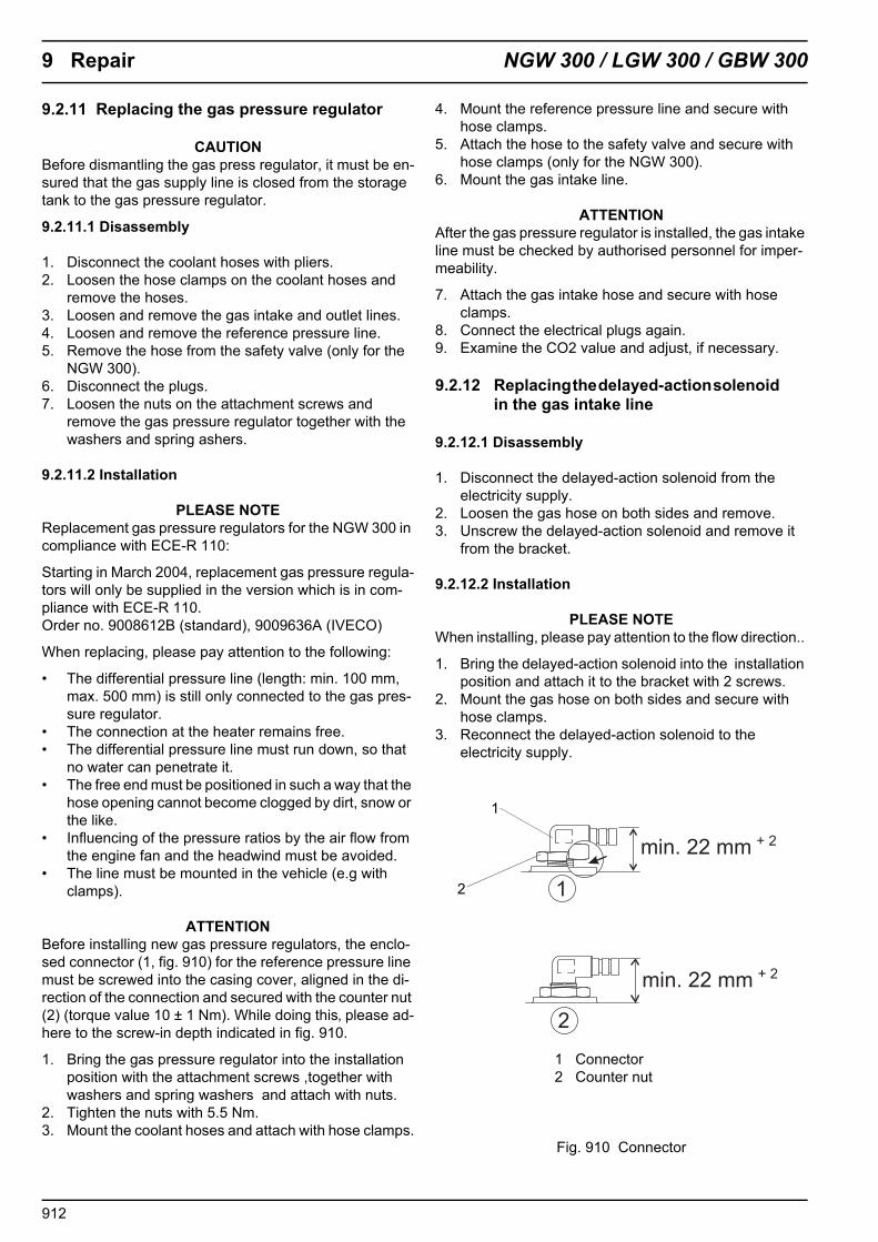
9 Repair NGW 300 / LGW 300 / GBW 300
9.2.11 Replacing the gas pressure regulator
CAUTIONBefore dismantling the gas press regulator, it must be en-sured that the gas supply line is closed from the storage tank to the gas pressure regulator.
9.2.11.1 Disassembly
1. Disconnect the coolant hoses with pliers.2. Loosen the hose clamps on the coolant hoses and
remove the hoses.3. Loosen and remove the gas intake and outlet lines.4. Loosen and remove the reference pressure line.5. Remove the hose from the safety valve (only for the
NGW 300).6. Disconnect the plugs.7. Loosen the nuts on the attachment screws and
remove the gas pressure regulator together with the washers and spring ashers.
9.2.11.2 Installation
PLEASE NOTEReplacement gas pressure regulators for the NGW 300 in compliance with ECE-R 110:
Starting in March 2004, replacement gas pressure regula-tors will only be supplied in the version which is in com-pliance with ECE-R 110. Order no. 9008612B (standard), 9009636A (IVECO)
When replacing, please pay attention to the following:
• The differential pressure line (length: min. 100 mm, max. 500 mm) is still only connected to the gas pres-sure regulator.
• The connection at the heater remains free.• The differential pressure line must run down, so that
no water can penetrate it.• The free end must be positioned in such a way that the
hose opening cannot become clogged by dirt, snow or the like.
• Influencing of the pressure ratios by the air flow from the engine fan and the headwind must be avoided.
• The line must be mounted in the vehicle (e.g with clamps).
ATTENTIONBefore installing new gas pressure regulators, the enclo-sed connector (1, fig. 910) for the reference pressure line must be screwed into the casing cover, aligned in the di-rection of the connection and secured with the counter nut (2) (torque value 10 ± 1 Nm). While doing this‚ please ad-here to the screw-in depth indicated in fig. 910.
1. Bring the gas pressure regulator into the installation position with the attachment screws ,together with washers and spring washers and attach with nuts.
2. Tighten the nuts with 5.5 Nm.3. Mount the coolant hoses and attach with hose clamps.
4. Mount the reference pressure line and secure with hose clamps.
5. Attach the hose to the safety valve and secure with hose clamps (only for the NGW 300).
6. Mount the gas intake line.
ATTENTIONAfter the gas pressure regulator is installed, the gas intake line must be checked by authorised personnel for imper-meability.
7. Attach the gas intake hose and secure with hose clamps.
8. Connect the electrical plugs again.9. Examine the CO2 value and adjust, if necessary.
9.2.12 Replacing the delayed-action solenoid in the gas intake line
9.2.12.1 Disassembly
1. Disconnect the delayed-action solenoid from the electricity supply.
2. Loosen the gas hose on both sides and remove.3. Unscrew the delayed-action solenoid and remove it
from the bracket.
9.2.12.2 Installation
PLEASE NOTEWhen installing, please pay attention to the flow direction..
1. Bring the delayed-action solenoid into the installation position and attach it to the bracket with 2 screws.
2. Mount the gas hose on both sides and secure with hose clamps.
3. Reconnect the delayed-action solenoid to the electricity supply.
Fig. 910 Connector
min. 22 mm
min. 22 mm
+ 2
+ 2
1
2
2
1
1 Connector2 Counter nut
912

NGW 300 / LGW 300 10 Packaging/Storage/Shipping
10 Packaging/Storage/Shipping
10.1 General information
The heater or its components, which are shipped to Spheros GmbH for checking or repair, must be cleaned and packed in such a way that they are protected from damage during handling, trasnportation and storage. A description of the defect must be enclosed.
ATTENTIONIf an entire heater is being sent back, it must be completely emptied. When packaging or shipping the appliance, care must be taken to ensure that no coolant can leak out. The coolant inlets and outlets must be closed with blind plugs. The ambient temperatures listed in paragraph 4 must not be exceeded during storage.
1001

10 Packaging/Storage/Shipping NGW 300 / LGW 300
Blank page for notes
1002