web2.utc.eduweb2.utc.edu/~qvp171/2015 Concrete Canoe(FAMU)/Kokomoa... · Web viewCrowe, Clayton T,...
29
FAMU – FSU Kokomoa i
Transcript of web2.utc.eduweb2.utc.edu/~qvp171/2015 Concrete Canoe(FAMU)/Kokomoa... · Web viewCrowe, Clayton T,...

FAMU – FSU Kokomoa
i

FAMU – FSU Kokomoa
i

FAMU – FSU Kokomoa
Executive Summary The FAMU - FSU College of Engineering is a joint college between the two major universities located in Tallahassee Florida; Florida Agricultural and Mechanical University (FAMU) and Florida State University (FSU). Established in 1982 and home to around 2000 students and faculty from 22 different countries. The college is located in Tallahassee's high tech research and manufacturing district Innovation Park. Innovation Park is also home to the National High Magnetic Field Laboratory, the Center for Advanced Power Systems, the Florida Center of Advanced Aero Propulsion, the Florida Department of Transportation Research Laboratory, and FSU’s High Performance Materials Institute. This puts the college in the prime location for the advancement of all branches of the engineering disciplines. In 2012, FAMU - FSU hosted the ASCE Southeastern Student Conference and thanks to a well-designed canoe, Lea, the team placed 3rd overall in the concrete canoe competition. As a result, the 2013 Concrete Canoe team went to conference hoping to better that score with Abbey. Abbey was a well-designed canoe but was only able to place 5th overall in concrete canoe competition. With back to back top 5 wins there was a lot of anticipation for the 2014 concrete canoe team to head to conference with their newest canoe, Ziracony and see how it would perform. Ziracony had a hull that was based heavily on the design of Abbey, which left plenty of time to improve the mix
design which was overly heavy and weak. Unfortunately, when put up against a field of increasing numbers of male molded high tech concrete canoes, Ziracony failed to live up to expectations and was only able to bring home a 14 th
place finish. This was a wakeup call for this year’s team to totally revamp the entire program and make the switch to a male mold design, start researching entirely lightweight aggregates in the concrete mix, and to start research in high and low range water reducing admixtures. The result of all of this is a totally new type of canoe for the FAMU – FSU College of Engineering. The transition was not the smoothest ever and not without a few delays due to the previously unused mix designs. However Kokomoa was born February 22nd. With its revolutionary design Kokomoa will finally bring this program into the 21st century and the success of Kokomoa will undoubtedly set the standard for hull design and mix design potential at the FAMU – FSU College of Engineering for years to come.
ii

FAMU – FSU Kokomoa
Specifications for KokomoaLength 21'4"Width (max) 28"Depth (max) 16"Thickness 1/2"Projected Weight 250 poundsStrength 1480psi.
Reinforcementbasalt fibers and basalt mesh
Colorsyellow, orange, white and red
Table #1
ii

FAMU – FSU Kokomoa
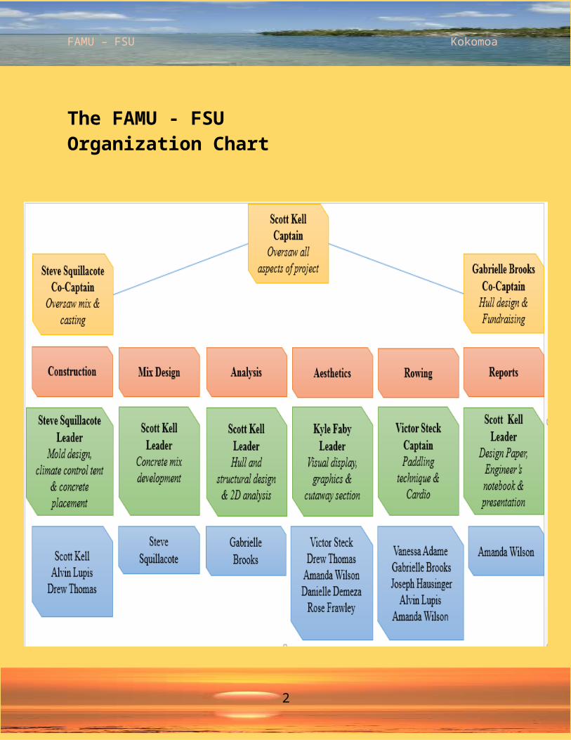
Project managementThe captain of the competition assigned two co-captains to help out with different aspects of creating the canoe. The captain wanted to have semi-direct control over the mix design for the canoe so there were co-captains assigned for the hull design and mix design. The rowing team and visual display had people placed in charge but they were left under the watch of the captain. The greatest challenge that faced the teams was the fact that there was no previous information to fall back on, so there was definitely a sense of urgency for all the captains to try to hit the mark perfectly the first time.
Once teams had been setup there was a safety meeting for all the teams so that the proper safety equipment and the proper operating procedures were understood by all participants of the concrete canoe team. There were also safety meetings among the individual teams so that the hazards of the materials that were being used were fully understood. Safety Equipment was always on hand for every workday to ensure the well-being of the team. The mix design team had the most equipment as they needed ear, eye and respiratory protection.
The captains all met up on a weekly basis so that any issues that were run into could be discussed with the entire team. This ensured that there wouldn’t be any surprises run into once the entire project was put together. There was a significant delay in starting the project due to the fact that funding was not received until the first week of January. The time during winter break was spent procuring donations from as many of the suppliers as possible. Once the funding was received there was a vast amount
of work to be done on the canoe if it was to be done in time for conference.
The time spent on every aspect of the canoe build can be seen in the breakdown of labor hours in Figure #1.
mix design; 1100; 36%
hull design; 550; 18%
construction; 630; 21%
fundraising; 560; 18%
design paper; 200; 7%
Figure #1: Project Man-HoursAs can be seen from Figure #1 there was a lot more time put into the mix design that any other aspects of the project.
The costs associated with the canoe were paid for through the solicitation of donations from local engineering firms, funding from the Student Government Association and the rest was taken care of through the donations of materials from the suppliers that were used. To ensure proper oversight of funding, the college’s ASCE student branch president allocated the funds and resources for all the material purchases. The expenses for the concrete canoe competition are illustrated in Figure #2 below.
$200
$1,000
$40
$800 Visual displayMix MaterialsToolsConstruction
Figure #2: Financial Costs
1

FAMU – FSU Kokomoa
The FAMU - FSU Organization Chart
2

FAMU – FSU Kokomoa
Hull design
The most challenging aspect of the entire changeover that the college went through was the fact that nobody at the college had ever built a mold for a boat of this nature before. The first thing that was looked at was whether the hull from a white water rafting canoe would have the characteristics that were desired. After extensive research was performed using methods from “Clayton Crowe’s Engineering Fluid Mechanics”, it was determined that most racing canoes with fiberglass canoe hulls always came back to the same problem, which was a lack of water displacement. This meant that the canoe either wouldn’t float or floated right at the water’s surface when loaded with the row team. The proposed solution was to take the generic hull design that is provided by the conference website and to modify it extensively with respect to the width and height of the sides. The design also was chosen because there was a section of sixteen feet where the bottom was effectively flat which gave maximum water displacement. It also caused the canoe to ride further out of the water creating less drag and allowed the canoe to turn with less effort as a result of the well-shaped rockers. The canoe was modeled in MD Solids as a simple beam with pin supports acting as the rowers in the canoe during the coed race. From the analysis it was determined that the canoe experienced a maximum positive shear stress of 160 pounds at 8 feet back from the bow and a maximum negative shear stress at 12 feet back from the bow. The moments that the canoe experienced were a pair
of maximum positive moments of 115lb*ft. at 8 and 12ft back from the bow and maximum negative moments of 100lb*ft. at 5.35 and 14.65 feet back from the bow. There was no need to run an analysis of the canoe for transportation due to the fact that it would be riding effectively on an air bag when being transported in the canoe carrier. Not having access to strain gauge equipment there was no way of verifying what stresses or strains that the canoe underwent when it was being lifted out of the carrier case or when the rowers were racing it. The analysis of the canoe that was done in MD Solids can be seen in figure 3.
Figure #3: Shear and Moment StressesWhen designing the concrete strength it was determined there should be basalt mesh placed along the bottom and from side to side along the entire length of the canoe. This was done to ensure that the concrete had to resist as little tensile stress on the walls and bottom as possible. The basalt mesh that was decided on had a tensile strength of 701.98ksi which seemed to be adequate considering the concrete used had a compressive strength of 1480psi. The strength of this year’s concrete was
3

FAMU – FSU Kokomoa
greater than any concrete used to construct a canoe at the
3
FAMU – FSU Kokomoa
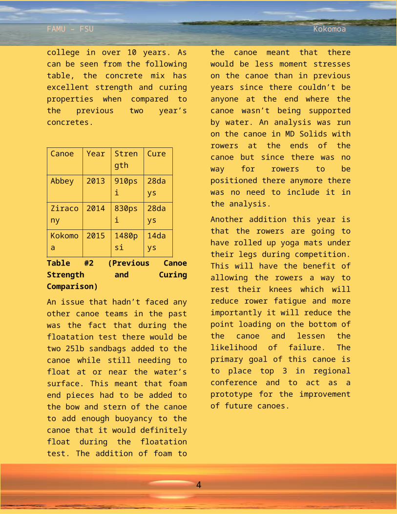
college in over 10 years. As can be seen from the following table, the concrete mix has excellent strength and curing properties when compared to the previous two year’s concretes.
Canoe Year Strength
Cure
Abbey 2013 910psi 28days
Ziracony
2014 830psi 28days
Kokomoa
2015 1480psi
14days
Table #2 (Previous Canoe Strength and Curing Comparison)
An issue that hadn’t faced any other canoe teams in the past was the fact that during the floatation test there would be two 25lb sandbags added to the canoe while still needing to float at or near the water’s surface. This meant that foam end pieces had to be added to the bow and stern of the canoe to add enough buoyancy to the canoe that it would definitely float during the floatation test. The addition of foam to the canoe meant that there would be less moment stresses on the canoe than in previous years since there couldn’t be anyone at the end where the canoe wasn’t being supported by water. An analysis was run on the canoe in MD Solids with rowers at the ends of the canoe but since there was no way for rowers to be positioned there anymore there was no need to include it in the analysis.
Another addition this year is that the rowers are going to have rolled up yoga mats under their legs during competition. This will have the benefit of allowing the rowers a way to rest their knees which will reduce rower fatigue and more importantly it will reduce the point loading on the bottom of the canoe and lessen the likelihood of failure. The primary goal of this canoe is to place top 3 in regional conference and to act as a prototype for the improvement of future canoes.
4

FAMU – FSU Kokomoa
Development and testing The team decided that this year there would be no extreme compromises in the strength of the concrete for the sake of a light weight concrete. The goal for this year was to produce a concrete design that would float and have a compressive strength of over 1000psi. Due to an extremely limited time frame as well as a limited amount of materials, there weren’t large enough batches made to test for compressive strength, flexural strength, and tensile strength. As a result it was determined that the compressive strength of the concrete would be the only test performed because that test is the one that has the greatest significance for the canoe strength since it will be embedded with basalt mesh to increase the tensile properties of the canoe. The basalt mesh will be completely embedded between the layers of concrete so the concrete will behave like it has high tensile and compressive strength qualities
When testing began three different test batches of concrete were made with different admixtures and water contents. The first batch of concrete that was poured had a w/cm ratio that was too high causing the concrete behaved like a self-consolidating concrete. The second batch had an air entrainer in it and although it was quite workable it failed to reach the 1000psi compressive strength test so it was discarded immediately. The third batch had a water content that was almost perfect for placing the concrete as well as over 1000psi strength so the third batch was
chosen for further modification to a perfect concrete mix for the canoe. After that several modified batches of the third concrete mix were tested with varying w/cm ratios until a mix was chosen that had the right consistency to be troweled onto the mold and not have any issues with slumping off the mold before curing. It was at this stage that the captain and mix design co-captain decided to test how the concrete behaved when it was poured in the lab that was being used to build the canoe. After several batches of concrete were made all exhibiting the same results, it was determined that the admixtures being used had serious problems with a temperature that dropped below 65ºF during the initial curing process. The concrete failed to cure any further than to skin over for two days at which point it would appear to start curing normally. Once this fact was determined it was also determined that there wouldn’t be a set of 7-10 days in a row where the temperatures would stay high enough to pour the canoe properly. This was when the miniature clean/climate control room was designed and built by the captain and co-captain. The room had three benefits to the project. It could be used to house the canoe during the curing process, it would contain the dust from sanding the canoe, and didn’t have to be budgeted. This was due to the fact that it was designed out of full length pieces of lumber that were going to be part of the visual display that could be installed after the canoe was birthed and sanded.
The aggregates and mesh that were chosen to be used in the mix design of
5

FAMU – FSU Kokomoa
the canoe had 2 design criteria that preferably needed to be met before they were considered, extreme light weight
5

FAMU – FSU Kokomoa
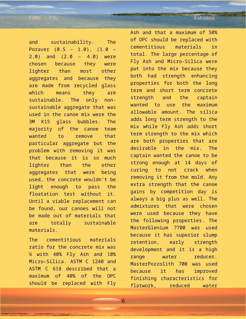
and sustainability. The Poraver (0.5 – 1.0), (1.0 – 2.0) and (2.0 – 4.0) were chosen because they were lighter than most other aggregates and because they are made from recycled glass which means they are sustainable. The only non-sustainable aggregate that was used in the canoe mix were the 3M K15 glass bubbles. The majority of the canoe team wanted to remove that particular aggregate but the problem with removing it was that because it is so much lighter than the other aggregates that were being used, the concrete wouldn’t be light enough to pass the floatation test without it. Until a viable replacement can be found, our canoes will not be made out of materials that are totally sustainable materials.
The cementitious materials ratio for the concrete mix was ½ with 40% Fly Ash and 10% Micro-Silica. ASTM C 1240 and ASTM C 618 described that a maximum of 40% of the OPC should be replaced with Fly Ash and that a maximum of 50% of OPC should be replaced with cementitious materials in total. The large percentage of Fly Ash and Micro-Silica were put into the mix because they both had strength enhancing properties for both the long term and short term concrete strength and the captain wanted to use the maximum allowable amount. The silica adds long term strength to the mix while Fly Ash adds short term strength to the mix which are both properties that are desirable in the mix. The captain wanted the canoe to be strong enough at 14 days of curing to not crack when removing it from the mold. Any extra
strength that the canoe gains by competition day is always a big plus as well. The admixtures that were chosen were used because they have the following properties. The MasterGlenium 7700 was used because it has superior slump retention, early strength development and it is a high range water reducer. MasterPozzolith 700 was used because it has improved finishing characteristics for flatwork, reduced water content for a given workability hull cracking reduction due to the retarder and it is a water reducing retarder. MasterSet AC122 was used because it has accelerated set times and it has increased early and ultimate compressive and flexural strengths
6
FAMU – FSU Kokomoa
Construction The mold started as a 40” by 276” table made out of 15/32” plywood. The materials for the mold were chosen to be wood because it was relatively inexpensive and both the captain and construction captain had experience working with wood in the construction field. The ribs were to be made out of 15/32” plywood that were connected together by 11.5” long 2”X4”s. The molding surface was made out of 1/8 oak paneling that was covered with plaster and sealed with gel-coat. The plaster and gel-coat were chosen because the plaster was thick enough to fill in all the imperfections that were in the oak paneling layer without being too difficult to sand smooth. The gel coat was used due to the fact that it was designed to undergo constant water and corrosion attacks and that it has an extremely strong, hard and smooth finish when it is sanded. The mold construction was to be completed in several phases. The first phase was to take the CAD design that we had made and to get it printed out onto sheets of paper. Then glued onto the plywood which were cut out into the ribs of the canoe. An idea that was decided on was to make duplicates of 4 of the ribs so that the mold was divided into five segments to make removing the canoe from the mold easier and possibly make the mold reusable. Every segment from that point on was built to be a stand-alone unit that would be screwed together when it was time to pour the canoe.
Figure #4: Bow Rib-SectionOnce the rib sections were completed the task of gluing all the pieces of oak paneling began. Once that was done, all the edges were sanded so that they would fit together perfectly. The next step was to plaster the entire mold so that all the little imperfections in the paneling wouldn’t show on the inside of the canoe. The plaster was then sanded and five coats of gel-coat were applied to give the mold a slick and hard outer surface for the concrete to be placed on without worrying about it sticking to the mold. Once the gel-coat was applied it was wet sanded with 400, 800 & 2000 grit sandpaper and buffed to give it a perfect finish to keep sanding on the inside of the canoe to a minimum.
The concrete was placed on the mold by hand and it was smoothed out using concrete trowels. The process of placing the concrete was for a 3 person team to mix 3ft^3 batches of concrete at a time while 7 people placed the concrete. The 7 people placing concrete were broken into 2 teams of 3 while one person with a depth gauge constantly performing quality control on the thickness of the layers.
7

FAMU – FSU Kokomoa
Figure #5: Concrete Placement
A 5/8” thick layer of concrete was placed where the foam ends met the mold with a layer of mesh being placed at mid-thickness of the concrete layer. Once the ends were placed the concrete was placed from end to end on the mold as if there was a complete mold underneath the concrete. There was a layer of mesh placed along the bottom of the canoe which was covered with a ¼” of concrete before mesh was run from side to side along the entire length of the canoe. The final 1/8” of concrete was a skim-coat that was designed to give a smooth finish on the outside of the canoe to reduce sanding time. The concrete was smoothed out perfectly and then the canoe was left to cure for 12hrs before being wrapped in burlap. The burlap was soaked in warm water so that the concrete could hydrate and gain strength.
After 14 days the canoe was removed from its mold by removing the two 1ft long mold sections which allowed the end pieces to slide toward the middle of the canoe. Once the easy removal stage was done and there was plenty of room for people to gather around the middle the center piece was popped out of the canoe. Once the canoe was removed from the mold and sanded inside the dust control room, it wiped down with wet cloths so that painting could begin. After the painting had been finished the canoe was sealed and made ready for its trip to the conference.
8

FAMU – FSU Kokomoa
Kokomoa Project Schedule
9
FAMU – FSU Kokomoa
Kokomoa Design drawing
10

FAMU – FSU Kokomoa
Appendix a: references3M. (2010). "3M (TM) Glass Bubbles K15." www.3m.com. (Feb. 14, 2015).
Poraver. (2010). “Poraver ™ (0.5 – 1.0) Expanded Glass Bubbles”. www.Poraver North America.com (Feb. 16, 2015)
Poraver. (2010). “Poraver ™ (1.0 – 2.0) Expanded Glass Bubbles”. www.Poraver North America.com (Feb. 16, 2015)
Poraver. (2010). “Poraver ™ (2.0 – 4.0) Expanded Glass Bubbles”. www.Poraver North America.com (Feb. 16, 2015)
ASTM C 33, “Standard Specification for Concrete Aggregate,” ASTM International.
ASTM C 39/C 39M, “Standard Test Method for Compressive Strength of Cylindrical Concrete Specimens,” ASTM International.
ASTM C 150, “Standard Specification for Portland Cement,” ASTM International.
ASTM C 494/C 494M, “Standard Specification for Chemical Admixtures for Concrete,” ASTM International.
ASTM C 618, “Standard Specifications for Coal Fly Ash and Raw or Calcined Natural Pozzolan for Use as a Mineral Admixture in Concrete,” ASTM International.
ASTM C 989, “Standard Specification for Ground GranulatedBlast Furnace Slag for Use in Concrete and Mortars,” ASTM International.
ASTM C 1240, “Standard Specification for Use of Silica Fume as a Mineral Admixture in
Hydraulic Cement Concrete, Mortar, and Grout,” ASTMInternational.
Crowe, Clayton T, Donald Elger, Barbara Williams, and John Roberson. Engineering Fluid Mechanics. 9th ed. John Wiley and Sons Inc. 2009. Print.
.
A1

FAMU – FSU Kokomoa
Appendix b: mixture Proportions
B1
FAMU – FSU Kokomoa
Appendix b: MixtureProportions
B2

FAMU – FSU Kokomoa
Appendix c:Bill of materials
C1