file · Web viewGuide to the use of the paradigm (to writers of tender documents) In order to make...
27
Guide to the use of the paradigm (to writers of tender documents) In order to make it easier and faster for you to formulate tender documents, the Danish Road Directorate (DRD) has prepared tender paradigms, which must be used when inviting tenders for tasks from consultants and contractors. The entire guide serves as a help to you and should of course be removed so that it does not appear in the finished document. It is crucial that we describe our orders in detail so there is no doubt as to the delivery we want. When we base the tender documents on a uniform and recognisable structure, we make the entire procurement process easier for you as an employee of the DRD and for our suppliers. The paradigms are changed on an ongoing basis in connection with new laws, executive orders and standards as well as the experience gained by the DRD, our wishes for rationalisation and much more. THEREFORE, YOU MUST ALWAYS USE PARADIGMS WHEN PREPARING TENDER DOCUMENTS! You CANNOT just find a previous tender document and "simply" adjust it as it may have become obsolete in the meantime. In order to make the writing process as easy as possible for you, the guide is part of the appearance of the paradigm itself. The meaning of the different colours, markings and brackets are as follows: Red text is a guide for you. It can be deleted when you are ready. The red text MUST be deleted no later than in connection with completion of the document. Black text on a white background is standard text applicable to all contracts. As a general rule, this text should NOT be deleted or changed. However, you have to delete it, if a section or a text is not at all relevant for your tender. Black text with a turquoise shading colour is text that should be adjusted to match the specific project.
Transcript of file · Web viewGuide to the use of the paradigm (to writers of tender documents) In order to make...

Guide to the use of the paradigm (to writers of tender documents)In order to make it easier and faster for you to formulate tender documents, the Danish Road Directorate (DRD) has prepared tender paradigms, which must be used when inviting tenders for tasks from consult-ants and contractors.
The entire guide serves as a help to you and should of course be removed so that it does not appear in the finished document.
It is crucial that we describe our orders in detail so there is no doubt as to the delivery we want. When we base the tender documents on a uniform and recognisable structure, we make the entire procurement process easier for you as an employee of the DRD and for our suppliers.
The paradigms are changed on an ongoing basis in connection with new laws, executive orders and standards as well as the experience gained by the DRD, our wishes for rationalisation and much more.
THEREFORE, YOU MUST ALWAYS USE PARADIGMS WHEN PREPARING TENDER DOCUMENTS!
You CANNOT just find a previous tender document and "simply" adjust it as it may have become obsolete in the meantime. In order to make the writing process as easy as possible for you, the guide is part of the appearance of the paradigm itself. The meaning of the different colours, markings and brackets are as fol-lows:
Red text is a guide for you. It can be deleted when you are ready. The red text MUST be deleted no later than in connection with completion of the document.
Black text on a white background is standard text applicable to all contracts.As a general rule, this text should NOT be deleted or changed. However, you have to delete it, if a section or a text is not at all relevant for your tender.
Black text with a turquoise shading colour is text that should be adjusted to match the specific pro-ject.
The text should EITHER be included unchanged or removed OR be made more specific for the particular task – see the explanation below of the two types of brackets.
It is important that the turquoise shading is used for entire sections to facilitate the final editing. The shading must appear as one text block and not as in this sections where only the lines are shaded. If you only apply shading to single words or sentences, the guide to remov- ing shading colour does not work.
Make sure that you use the right turquoise colour by se- lecting the style "Turkis skyggefarve" (Turquoise shading) – or by selecting this specific colour:
The turquoise shading should be maintained until after you have read the document and be removed immediately before tender. Remove all shading in the entire document in one step by doing the follow-ing:
Ctrl+A (select all) -> tilted paint bucket (shading) -> select ”no colour”.
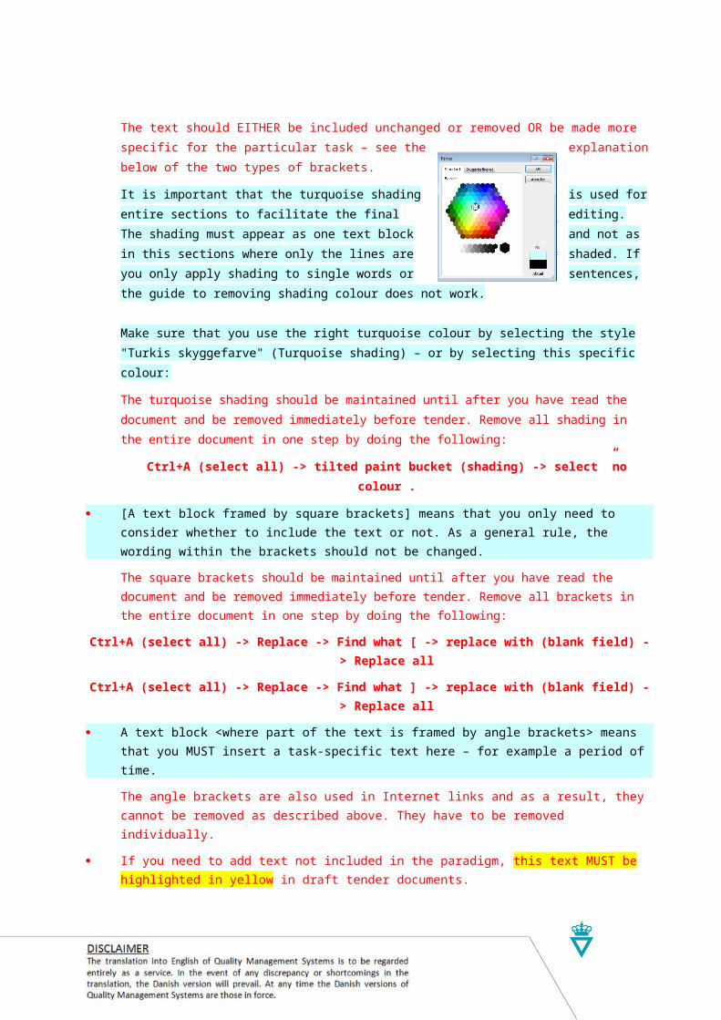
[A text block framed by square brackets] means that you only need to consider whether to include the text or not. As a general rule, the wording within the brackets should not be changed.
The square brackets should be maintained until after you have read the document and be removed immediately before tender. Remove all brackets in the entire document in one step by doing the follow-ing:
Ctrl+A (select all) -> Replace -> Find what [ -> replace with (blank field) -> Replace all
Ctrl+A (select all) -> Replace -> Find what ] -> replace with (blank field) -> Replace all
A text block <where part of the text is framed by angle brackets> means that you MUST insert a task-specific text here – for example a period of time.
The angle brackets are also used in Internet links and as a result, they cannot be removed as de-scribed above. They have to be removed individually.
If you need to add text not included in the paradigm, this text MUST be highlighted in yellow in draft tender documents.
In order to make the work as easy for you as possible and ensure that the finished document is without faults, you should proceed in this order:1. Read this guide every time, even if you think you remember its content. Consider printing it.
2. Make one document – SBB – for all documents.
3. Enable track changes in Word and set it so you do not see the changes but only the final docu-ment. The changes can always be made visible if you need it.
4. Delete the sections in the document that are not relevant for your tender.
5. Consider text with turquoise shading – either in [square] or <angle> brackets.
6. Add text if required. Mark it using yellow highlighting colour.
7. Delete red text when you are sure that you have understood the guide. You can make the text vis-ible again as long as you have not "accepted" the changes in Word.
8. Read the document carefully. Does it all make sense?
9. Do not proceed to item 9 UNTIL YOU AND THE DOCUMENT OWNER are sure that everything is correct and can be understood unambiguously by the supplier.
10. "Accept all changes" and remove the blue and yellow highlights and make all text black. Disable track changes.
The red table at the bottom of the page is used for document management, which takes place in several steps: In connection with the approval of a specific paradigm (e.g. Drainage), the form must be completed
by the paradigm owner.
Delete the form when you have prepared a project-specific document.
If you discover any errors in the paradigm or if you have any suggestions for improvements, please con-tact the unit or network responsible for the paradigm. Changes must be approved in accordance with the "Procedure for maintenance of tender paradigms".

APPROVED UNIT/NETWORK SPECIALIST THEME SCHEDULED AUDIT DOCUMENT NO. ACCESS
MIAN 1 July 2015 AD-PV/Road Equipment Procurement and Contract-ing
June 2019 13/19296-8 [ ] Internal[ x ] External
THE SECTION BELOW SHALL BE INSERTED INTO THE GENERAL DOCUMENT AND ADJUSTED TO THE CURRENT PROCUREMENT.
Paradigm
SWS – Common to Design (Street Lighting)Procurement for Design-build contracts
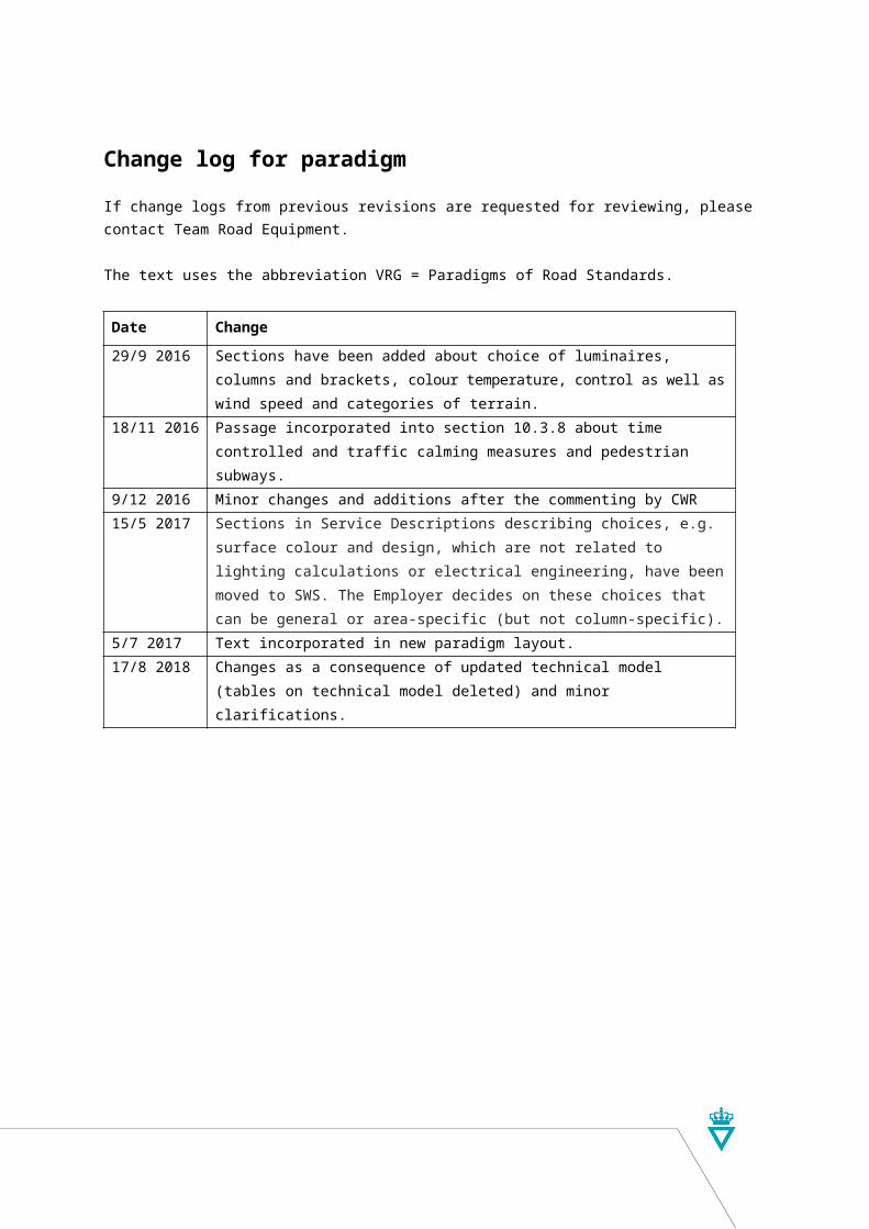
Change log for paradigmIf change logs from previous revisions are requested for reviewing, please contact Team Road Equip-ment.
The text uses the abbreviation VRG = Paradigms of Road Standards.
Date Change
29/9 2016 Sections have been added about choice of luminaires, columns and brackets, colour temperature, control as well as wind speed and categories of terrain.
18/11 2016 Passage incorporated into section 10.3.8 about time controlled and traffic calm-ing measures and pedestrian subways.
9/12 2016 Minor changes and additions after the commenting by CWR15/5 2017 Sections in Service Descriptions describing choices, e.g. surface colour and
design, which are not related to lighting calculations or electrical engineering, have been moved to SWS. The Employer decides on these choices that can be general or area-specific (but not column-specific).
5/7 2017 Text incorporated in new paradigm layout.17/8 2018 Changes as a consequence of updated technical model (tables on technical
model deleted) and minor clarifications.

PAGE6 of 21
SWS – Common to Design <contract number>
10 Street lighting
10.1 GeneralA project – for lighting of the below areas – is to be prepared. The exact boundaries of the areas shall be defined, considering the geometric detailed design and interfaces to the surroundings.
It shall be stated where you want the street lighting. The division into areas shall corres-pond to the requirements for lighting classes.
The final extent of lighting is determined by the contractor's consultant because there are interfaces to the existing lighting outside the scope of the contract and the geometric detailed design. The below specification of illuminated areas should therefore be able to accommodate adaptations to the surroundings and the geometry. Stationings are there-fore indicative. Alternatively, areas can be graphically illustrated on a drawing.
Area<motorway> <from Ch.> – <to Ch.>
<principal highway> <from Ch.> – <to Ch.>
<main road> <from Ch.> – <to Ch.>
<intersection> <Ch.>
<roundabout> <Ch.>
<local road> <from Ch.> – <to Ch.>
<path> <from Ch.> – <to Ch.>
<pedestrian street> <from Ch.> – <to Ch.>
<pedestrian crossing> <Ch.>
<car park> <Ch.>
<carpool location> <Ch.>
<bus stop> <Ch.>
<traffic calming measures> <Ch.>
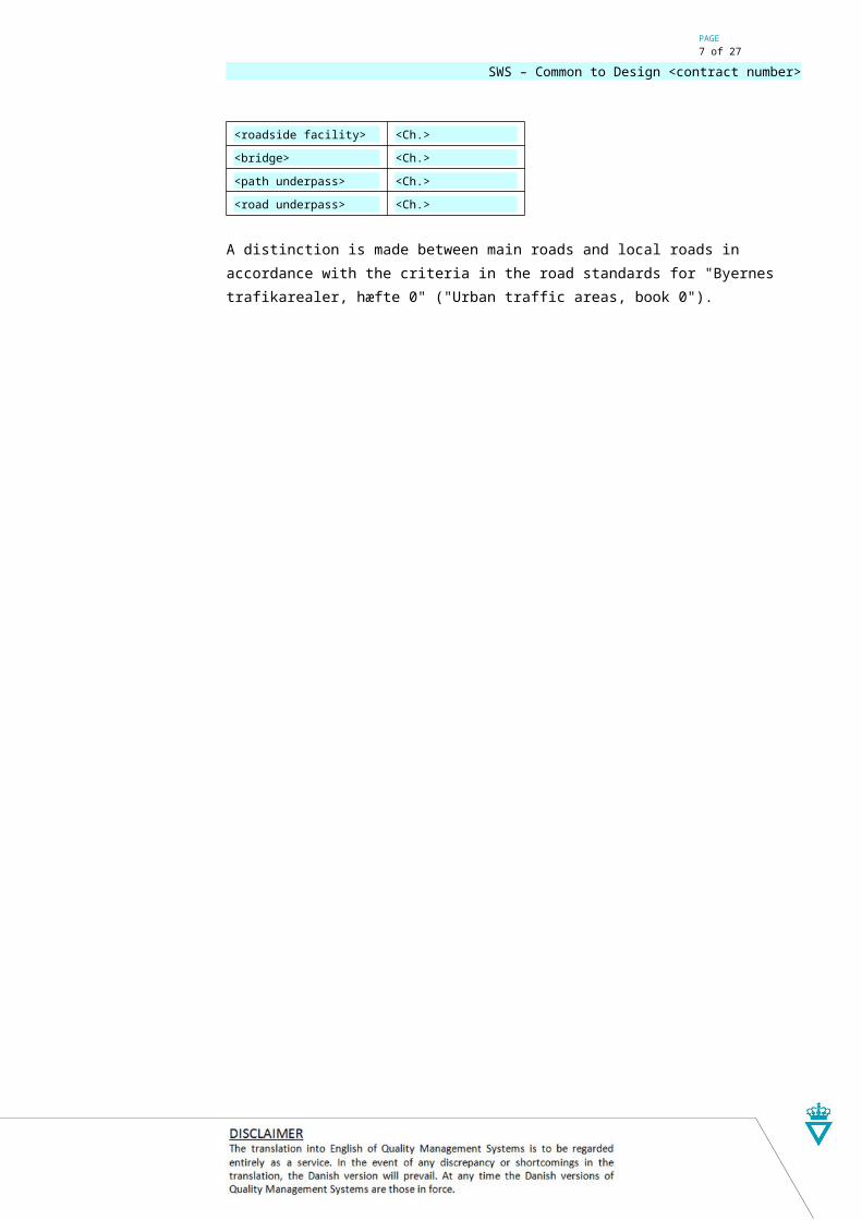
<roadside facility> <Ch.>
<bridge> <Ch.>
<path underpass> <Ch.>
<road underpass> <Ch.>
A distinction is made between main roads and local roads in accordance with the criteria in the road standards for "Byernes trafikarealer, hæfte 0" ("Urban traffic areas, book 0").
PAGE7 of 21
SWS – Common to Design <contract number>
10.2 Content of the projectGenerally, the project consists of three parts: project proposals, detailed project and ‘as built’ documentation. Each part consists of several activities of which some, in certain cases – depending on the scope and nature of the project – can be left out while others (e.g. light calculations) are iterative processes and therefore must be completed several times.
In the project, not all types of products mentioned – e.g. brackets and bridge mount brackets – are necessarily included.
The Employer shall do the handover inspection of the project proposal, detailed project and documentation. Any comments by the Employer on the project proposal shall be included in the detailed project. The work cannot be handed over until the documentation has been checked by the Employer.
<3> weeks should be expected for each check, calculated from the handover date.
10.2.1 Project proposal
The Contractor shall prepare a project proposal. The project proposal defines all visible and geometrical conditions of the lighting system in cooperation with the Employer. The project proposal is the basis for the detailed project.
The preparation of the project proposal mainly comprises the following activities:
Retrieving information on existing and adjacent lighting systems, including types of columns, luminaires and light sources as well as lighting control and electrical condi-tions
Defining the exact boundaries of each area based on road geometry and adjacent road equipment. Particularly for boundaries at interchanges see section 10.3.2 "Inter-changes"
Incorporating considerations for land use, e.g. high voltage electricity pylons, public utilities as well as railways and airports
Decide whether to use multifunctional columns in signal-controlled junctions
Clarifying whether the lighting system shall be designed for long vehicles and European modular systems (EMS) (vehicle path templates)
Incorporating extensive considerations for accessibility and safety for future operating and maintenance works
Choosing geometric arrangement (onesided, doublesided, staggered or doublesided over central reserve)
Choosing the shape of luminaires (hemisphere, dome, boat, disc or wedge), brackets (straight or curved) and columns (tapered, cylindrical or flanged). See section 10.3.3 “Shape of columns, brackets and columns”
Choosing the mount of the luminaires (post top, bracket, ceiling or wall). See section 10.3.4 “Mounting of luminaires”

PAGE8 of 21
SWS – Common to Design <contract number>
Determining the lowest lighting class for each area as described in "Handbook of Street Lighting"
Choosing luminaire family (out of requirements in “SWS – Street Lighting”, section 2.14 “Luminaires”)
Providing photometric data files (EULUMDAT format) for light calculations
Determining the maintenance factor. See section 10.4.1 “Maintenance factor”
Determining the luminance properties under diffuse illuminance Qd as well as reflec-tion level class for dry and wet carriageway in areas with luminance requirements (lighting classes L)
Perform light calculations with a view to estimate luminaire nominal height above ground of column and location of columns; mounting height, orientation and tilt angle of luminaires as well as luminaire fixing angle, bracket projection and mounting height of brackets
The framework for selection of the luminaire fixing angle and bracket projection is described in section 10.3.5 “Luminaire fixing angle and bracket projection”
Preparing the technical model according to "ICT Basis and Requirements". See ts.vejdirektoratet.dk → Modelstandard → Fagmodeller → Belysning
The project proposal comprises the following deliveries as specified below:
Technical model.
10.2.2 Detailed project
Against a background of an approved project proposal, the Contractor shall draw up a detailed project. The detailed project shall define all technical details relating to the light-ing system. The basis is the project proposal and possible comments from the Employer.
The preparation of the detailed project comprises the following activities:
Incorporating changes decided for the project proposal
Clarifying interfaces vis-à-vis existing and future pipelines, including coordination with utility owners and drainage project
Determining the nominal colour temperature and colour rendering. See section 10.3.6 “Colour temperature and colour rendering"
Perform light calculations with a view to determining nominal height above ground and locations of columns; mounting height, orientation, tilt angle, flux package and optic of luminaires as well as luminaire fixing angle, bracket projection and mounting height of brackets
Choosing lighting control configuration (e.g. 50 % 8 hours) in luminaries. See section 10.3.7 “Lighting control”.
Determining the product designation of luminaires (out of result of light calculations and requirements in “SWS – Street Lighting”, section 2.14 “Luminaires”)
Determining the final location of columns. See section 10.3.8 “Mounting and location of columns”

PAGE9 of 21
SWS – Common to Design <contract number>
Determining the terrain category (I, II, III or IV) and reference wind speed (24 m/s or 27 m/s) for the location. See section 10.3.9 “Terrain category and reference wind speed”
Determining the properties of columns (passively safe or non-passively safe)
Determining speed class (70 km/h or 100 km/h) and energy absorption class (HE, LE or NE) for passively safe columns. See section 10.3.10 “Passively safe columns”
Determining product designation of lighting columns (out of nominal height above ground and poperties as well as requirements in “SWS – Street Lighting”, section 2.10 “Column”
Determining product designation of brackets (out of luminaire fixing angle and the bracket projection as well as requirements in “SWS – Street Lighting”, section 2.12 “Bracket”)
Determining the location of foundations (out of location of the columns)
Determining product designation of foundations (out of product designation of columns as well as requirements in “SWS – Street Lighting”, section 2.20 “Founda-tion”)
Sectioning the lighting system based on the administrative conditions as well as elec-trical and financial conditions. See section 10.3.11 “Sectioning the lighting system”
Determining the location of the street lighting cabinets. See section 10.3.12 “Location of street lighting cabinets”
Determining the location for possible connection cabinets
Determining product designation of connection cabinets and boxes (out of the num-ber of luminaire cables and requirements in “SWS – Street Lighting”, section 2.13 “Connection box”)
Determining phase distribution for luminaires. Luminaires are to be connected to the individual phases alternately (L1-L2-L3-L1…) to achieve an even load of the phases
Determining the routing for ground cables. If the location of the Distribution Network Operator’s junction cabinet can’t be determined at that point in time, the routing of the cable to the street lighting cabinet (service lateral) shall to be left out
Preparing electrical calculations in order to divide cables onto the distribution boards; determining material for conductors, number of conductors and cross sections of conductors (e.g. 4G6 mm2 CU) for ground cables, as well as determining the rated current on fuses in connection boxes and distribution board fuses in street lighting cabinets
Determining the routing and inner diameter of ducts. The inner diameter of the ducts shall be minimum 50% larger than the diameter of the cable or the cable harness
Determining the routing and diameter of ducts
Determining product designation of ducts (out of diameter as well as requirements laid down in "SWS – Street Lighting", section 2.18 "Cable ducts")
Creating lighting systems to be administered by the Danish Road Directorate, in the inventory system VejlysWeb according to “ICT Basis and Requirements”. See “Vejledning VejlysWeb”, section “Oprettelse af nyt anlæg”

PAGE10 of 21
SWS – Common to Design <contract number>
Specifying street lighting cabinets (on the basis of rated current on distribution board fuses) and submitting specifications to the Employer. See section 10.3.13 “Ordering street lighting cabinets”
Preparing a technical model according to "ICT Basis and Requirements". See ts.vej-direktoratet.dk → Modelstandard → Fagmodeller → Belysning
“SWS – Street Lighting” specifies the following:
o terrain category and reference wind speed at location
Preparing a light report that comprise calculation results and preconditions, including:
o lighting classes
o maintenance factor
o light properties of the road surfacing for areas subject to luminance require-ments
Preparing calculation of power consumption, Pcalc. See “SWS – Street Lighting”, section 5.6 “Energy efficiency”
Collect documentation of products being Contractor’s supplies, cf. “SWS – Street Lighting”, section 5.1 “Components with CE marking”
Detailed design comprises the following supplies as specified above:
Creation in VejlysWeb
Specification of street lighting cabinets
Technical model
Light report
Documentation of calculated power consumption
Documentation of products.
10.2.3 ‘As built’ documentation
The Contractor shall prepare ‘as built’ documentation.
The ‘as built’ documentation describes the project and the construction and is therefore based on designation of used products and actual data about location of used products. (measured location data).
The ‘as built’ documentation shall be divided according to the division of the lighting sys-tem on road authorities, so that relevant documentation is delivered to each road author-ity.
The providing of the ‘as built’ documentation comprises the following activities:
Entering data for lighting systems to be run by the Danish Road Directorate in the inventory system VejlysWeb according to “ICT Basis and Requirements”. See “Vejledning VejlysWeb”, section “Indtastning af anlægsdata”
Update the technical model according to "ICT basis and requirements" based on the designation of used products and measured location data

PAGE11 of 21
SWS – Common to Design <contract number>
Preparing a drawing and associated list of data (.pdf) based on the technical model
Collecting documentation of products being the Contractor’s supplies
Collecting documentation of any products being the Employer’s supplies except for street lighting cabinets where the supplier sends the documentation directly to the Employer
Controlling and approving construction control plan
Controlling and approving commissioning report pursuant to the Danish Wiring Regu-lation
Controlling and approving lighting report that comprise calculation results and precon-ditions
Measuring reports are included if required. Only relevant for large lighting systems as these are relatively high cost. Shall be consequentially amended in "SWS – Street Light-ing”, section 5.4 ”Construction”.
[Controlling and approving measuring report of the lighting system's photometric per-formance.]
Controlling and approving documentation of measured power consumption, Pmeas.
The ‘as built’ documentation comprises the following supplies as specified above:
Data in VejlysWeb
Technical model
Drawing and associated list of data (.pdf)
Documentation of products
Construction control plan
Commisioning report
Lighting report
Measuring reports are included if required. Only relevant for large lighting systems as these are relatively high cost. Shall be consequentially amended in "SWS – Street Light-ing”, section 5.4 ”Construction”.
[Measuring report of photometric performance]
Documentation of measured power consumption.
Documentation of products, construction control regime, commissioning report, lighting report[, measuring report of photometric performance] and documentation of measured and calculated power consumption shall be delivered as a combined document.
The project is to be handed over to the Employer as described in “ICT Basis and Require-ments”.

PAGE12 of 21
SWS – Common to Design <contract number>
10.3 Design basis
10.3.1 Documents
The following documents shall be used as the design basis:
ICT basis and requirements
Street Lighting HandbookSee english-vejregler.lovportaler.dk → Construction and Planning → Road equipment → Street Lighting → Street Lighting – Handbook
The following documents shall be deleted if they are covered in the SBB.
[Common to Road Equipment - GWSSee english-vejregler.lovportaler.dk → Tendering → Road Equipment and Road Marking → Common to Road Equipment → Common to Road Equipment – GWS
Street Lighting Equipment – GWSSee english-vejregler.lovportaler.dk → Tendering → Road Equipment and Road Marking → Street Lighting → Street Lighting Equipment – GWS]
Vejledning VejlysWebSe vejdirektoratet.dk → Vejsektor → Leverandørportal → Kvalitetsledelsessystem → Projektering og teknik → Vejudstyr → Vejbelysning → Vejledning VejlysWeb
Konsol til lysmast på bro (Danish Road Directorate’s construction drawing 25349) See ts.vd.dk → Typetegninger → Vejudstyr → 25349
The municipality's lighting plan or design manual.
10.3.2 Interchanges
In interchanges the slip roads and intersections are lit in cases where:
either the primary road (motorway or expressway) or the secondary road (the inter-secting main road) is lit
the intersection between slip road and the secondary road is signal-controlled
the intersection between slip road and the secondary road is a roundabout or rotary
there are complicated conditions on the secondary road with hatched road markings, bollards, turn lanes and the like.
At the intersection between slip road and secondary road, the columns are placed in ac-cordance with the same principles as with other signal-controlled intersections and round-abouts.
The section of the secondary road between the two lit intersections shall also be lit.
In cases where the primary road is not lit, lighting of the entrance slip road is established corresponding to the distance of 1-2 columns while the exit slip road is only lit by one column located right at the intersection. However, in partial cloverleaf / folded diamond type interchanges without separation between the entry slip road and the exit slip road, the lighting must be established along the entry slip road and past the separation point between the entrance slip road and the exit slip road.

PAGE13 of 21
SWS – Common to Design <contract number>
In cases where the primary road is lit, lighting is established on the full extent of the entry and exit slip road.
Below are 4 types of intersections. The extent of the lighting is outlined, in cases where none of the roads are lit.

PAGE14 of 21
SWS – Common to Design <contract number>
10.3.3 Shape of columns, brackets and columns
10.3.3.1 General
The selection of shape shall generally be uniform at a given road geometry and con-sidered relating to the surroundings including nearby or adjacent existing systems.
In cases where an installation is to be transferred to a municipality, instructions in the municipality's lighting plan or design manual shall be followed. See section 10.3.11 "Di-viding the lighting system".
10.3.3.2 Luminaires
Selection of shape may in many cases be limited by the required lighting performance, including available light distributions and lumen packages.
Below, possible shapes are described. You should generally select as many designs as possible or select "unspecified" so that the range of products is not limited.
Shape Description Geometry
Unspecified All shapes possible n/a
Hemisphere Housing shaped as a hemisphere.
Dome Housing shaped as an oval dome (an ellipsoid cut horizontally).
Boat Housing shaped as an ellipsoid cut horizontally and vertically ("a
boat turned upside down").
Disc Housing shaped as a section of a taper, cut with two parallel
planes perpendicular on the symmetry axis of the taper.

PAGE15 of 21
SWS – Common to Design <contract number>
Wedge Ellipsoid cut with two planes. The lower plane should differ from
0º to +12º from the horizontal plane. The upper plane should
differ from -20º to the deviation from the horizontal plane of the
lower plane. Positive indication is clockwise.
10.3.3.3 Brackets
The recommendation of the luminaire manufacturer should as a rule be followed, as the luminaire in many cases is intended for a certain shape (and luminaire fixing angel and bracket projection) of the bracket.
The lighting design can be the determining factor for selection of shape, as a certain lu-minaire fixing angel and bracket projection may be required. See section 3.5 "Luminaire fixing angel and bracket projection”.
10.3.3.4 Columns
The recommendation of the luminaire manufacturer should as a rule be followed, as the luminaire in some cases is intended for a certain shape of the column.
The shape of columns shall be chosen within the framework stated in the table below. An "X" means that the shape may be employed.
The framework for selecting shape can be changed by deleting or adding some of the options in the following table.
Type of area Tapered Cylindrical SteppedMotorway
Principal highway
Main road
Signal-controlled intersection
Roundabout
Pedestrian street
Pedestrian crossing
Traffic calming measures
Bridge
X X
Highway XLocal road
PathX X
Car park
Carpool location
Bus or tram stop
Roadside facility
X X X

PAGE16 of 21
SWS – Common to Design <contract number>
10.3.4 Mounting of luminaires
Luminaires can be designed for post-top and/or side entry mounting. Mounting side entry on a bracket is based on at least one of the following:
the luminaire is designed exclusively for side entry mounting (typically the hemi-spheres, dome and cone shapes)
more than one luminaire per column
lighting design requires a bracket projection
lighting design requires a certain luminaire fixing angel.
In underpasses, luminaires can be designed for ceiling or wall mounting. It is preferable to mount in the ceiling for protection against vandalism.
10.3.5 Luminaire fixing angle and bracket projection
The shape of the bracket of the column is, for aesthetic reasons, determining for the up-per and lower limits for the luminaire fixing angle and bracket projection, to be chosen within the framework indicated in the following table.
Shape Bracket projection Luminaire fixing angleStraight bracket 0,1-0,5 m 0°
0,5-1,0 m 3°
Curved bracket 0,3-0,5 m 0°
10.3.6 Colour temperature and colour rendering
Luminous efficacy from LED packages increases with rising colour temperature. There-fore, for the sake of the energy efficiency of the system, you should aim at a choice of colour temperature as high as possible. However, warm-white light with a rather low col-our temperature has advantages regarding light quality, including colour rendering.
Where pedestrians and cyclists are present, there is a need to recognize faces and smal-ler objects. Here, you should choose warm-white light with a nominal colour temperature of 3000 K and a good colour rendering, Ra ≥ 80. This applies in most cases, for instance, to roads and intersections within urban areas, paths, car parks, carpool locations, road-side facilities, pedestrian crossings, shopping malls and at bus stops.
Where pedestrians and cyclists are not present, you should choose a neutral white light with a nominal colour temperature of 4000 K and a modest colour rendering, Ra ≥ 70. This applies in most cases, for instance, to motorways and highways as well as intersec-tions and roundabouts in rural areas.
10.3.7 Lighting control
In most cases, stand-alone time controlled dimming (self-adjusting timer unit) should be specified in all area types, except intersections, roundabouts, pedestrian crossings, speed reducing measures and at bus stops. Lighting control is typically specified at 50% of rated light flux between 22-06 hours.
Luminaires are supplied with a receptacle (Zhaga Book 18) for future control and monitor-ing with a compatible OLC (Outdoor Luminaire Controller) and an associated Central

PAGE17 of 21
SWS – Common to Design <contract number>
Management System (CMS) system. Control and monitoring with an OLC will have prior-ity over stand-alone time controlled dimming.
10.3.8 Mounting and location of columns
The outer side of the column must have a distance to the asphalt edge of the road of at least 0.5 m and to the asphalt edge of a path of at least 0.3 m. The distance is recom-mended to be somewhat greater than the minimum requirements.
Columns (and foundations) must be placed appropriately in relation to the location of other objects, including road drainage (pipes, inspection chambers and ditches) and road equipment (traffic barriers and signs etc.)
The distance between the front of the column and the rear of the traffic barrier shall at least be equal to the deflection width of the traffic barrier, unless the column is rated passively safe. Columns must not be in line with traffic barrier poles.
Columns on bridges shall be mounted on a bridge mount bracket fastened to the edge beam of the bridge in accordance with ”Bridge Mount Bracket for Lighting Column on Bridge” (Danish Road Directorate’s construction drawing 25349). Bridge mount brackets may not be in line with traffic barrier poles. Columns mounted on brackets are usually located within the deflection width of the railing, regardless of its W-class.
10.3.9 Terrain category and reference wind speed
Terrain category is selected from the following table.
Terrain category
Description Picture
I Lakeshore and smooth flat country without signific-
ant vegetation and without obstacles as well as
coastal areas exposed to rough open sea.
II Farmland with boundary hedges and occasional
small farm structures, houses or trees etc. with a
distance of at least 20 times the height of the
structures.
III Suburban or industrial areas and permanent forest
etc. with a distance of no more than 20 times the
height of the structures
IV Urban areas in which at least 15 % of the surface
is covered with buildings and their average height

PAGE18 of 21
SWS – Common to Design <contract number>
exceeds 15 m.
The default choice of terrain category is II. Terrain category 0 is not employed on land.
In areas in Jutland with locations less than 25 km from Vesterhavet and Ringkøbing Fjord, 27 m/s shall be selected as reference wind speed. In other areas, select 24 m/s.
10.3.10 Passively safe columns
On roads where the permitted speed is greater than 50 km/h, columns must be passively safe. The requirement does not apply if the columns are either placed:
behind the traffic barrier (outside the deflection width of the traffic barrier)
outside the safety zone of the road
or otherwise so that they cannot be hit.
The Speed class is dependent on the permitted speed and is to be chosen as stated in the table below:
Permitted speed Speed class50 - 80 km/h 70 km/h
50 - 130 km/h 100 km/h
The Energy absorption class is chosen based on several conditions. LE and HE-columns are used at the following places:
where there may be a danger that mislead vehicles can collide with dangerous obstacles such as trees, bridge columns or noise barriers
where a lot of walking and cycling traffic is present
in traffic islands and central reservations
and on bridges.
Other places NE, LE and HE are selected.
The safety class is chosen as high as possible, at least 2.
10.3.11 Sectioning the lighting system
If the Danish Road Directorate is the only Road Authority, please state:[All areas shall be managed by the Danish Road Directorate and thus, for administrative reasons, the lighting system shall not be divided.]
If not all areas are to be managed by Danish Road Directorate, please specify the road authority responsible for operation and maintenance of the lighting system. [The Danish Road Directorate and other road authorities shall – for administrative reas-ons – have separate meter points. The lighting system shall therefore be divided in such a way that service lateral, cabinet, street lighting cables etc. are separate for each road authority.
In the table below, the road authority is specified for each area.

PAGE19 of 21
SWS – Common to Design <contract number>
Area Road authority
<motorway> <from Ch.> – <to Ch.> <road authority>
<principal highway> <from Ch.> – <to Ch.> <road authority>
<main road> <from Ch.> – <to Ch.> <road authority>
<intersection> <Ch.> <road authority>
<roundabout> <Ch.> <road authority>
<local road> <from Ch.> – <to Ch.> <road authority>
<path> <from Ch.> – <to Ch.> <road authority>
<pedestrian street> <from Ch.> – <to Ch.> <road authority>
<pedestrian crossing> <Ch.> <road authority>
<car park> <Ch.> <road authority>
<carpool location> <Ch.> <road authority>
<bus stop> <Ch.> <road authority>
<traffic calming measures> <Ch.> <road authority>
<roadside facility> <Ch.> <road authority>
<bridge> <Ch.> <road authority>
<path underpass> <Ch.> <road authority>
<road underpass> <Ch.> <road authority> ]Electrical limitations as to levels of short-circuit current and voltage at the columns in the greatest possible distance to the street lighting cabinet may render a division necessary for the system.
Where the distance between neighbouring areas is sufficiently great, financially, it is more profitable to divide the system.
10.3.12 Location of street lighting cabinets
The location shall be:
appropriately in relation to the location of road drainage (pipes, inspection chambers and ditches) and road equipment (traffic barriers and signs etc.)
where a collision is most unlikely
with good accessibility and safety for future operating and maintenance works, includ-ing at least 0.8 m distance to other objects in front of the cabinet throughout its width
coordinated with the location of the junction cabinet (property of the distribution net-work operator) and cabinets for other road-related systems (fi. traffic signals, traffic counters, CCTV’s and pumping stations).
10.3.13 Ordering street lighting cabinets
Street lighting cabinets are the Employer’s own supplies. The Employer shall be informed of the details below for each lighting system. The information is necessary for the Em-ployer to be able to specify the street lighting cabinet and thus a precondition that Em-ployer’s own supplies can be carried out.

PAGE20 of 21
SWS – Common to Design <contract number>
The future Local Authority of the cabinet (name of municipality or Danish Road Dir-ectorate)
Required delivery address and time of delivery
Indication of place of the lighting system (e.g. ”Roundabout on Vejlevej at TSA 21”)
The location of the cabinet, specified as coordinates in the reference system WGS 84 in the format ddd.ddddd°, i.e. degrees as decimal number (e.g. 55.65487°; 10.34078°). May be found by way of e.g. map.krak.dk. Right-click on the required location on the map, left-click afterwards on the button "GPS-koordinater". The name is WGS 84 decimal (lat, lon).
The registration number of the lighting system in the inventory system VejlysWeb
Name of Distribution Network Operator (utility company)
Number of conductors of the service lateral, cross section of conductors and material (e.g. 4·10 mm2 CU)
Size of the fuses (e.g. 3·35 A)
Type of meter (wires or plug pins)
Ikmin and Ikmax in the distribution panel (normally as specified in “Fællesregulativet”)
Number of groups, as 2 street lighting cables for each group
For each group:
o name of group (e.g. ”Columns in roundabouts”)
o the group cable’s number of conductors, cross section of conductors and mater-ial (e.g. 4·6 mm2 CU)
o size of the fuse per phase (e.g. 10 A)
o power consumption per phase.
PAGE21 of 21
SWS – Common to Design <contract number>
10.4 Design base
10.4.1 Maintenance factors
The overall maintenance factor, f M is selected based on the following:
f M=f LF ∙ f LM
luminous flux factor,f LF. Is equal to 1,00 when light output is constant throughout life time (CLO)
luminaire maintenance factor,f LM . Determination is based on the assessment of the load level of particles and the assumption of a cleaning interval of 6 year. Default value of f LM= 0,90.


![[ TENDER DOCUMENTS]](https://static.fdocuments.in/doc/165x107/629ddfbd1d2ce56160721a37/-tender-documents.jpg)