magbuhatrobotics.files.wordpress.com€¦ · Web viewbecause the change made to the steering is...
28
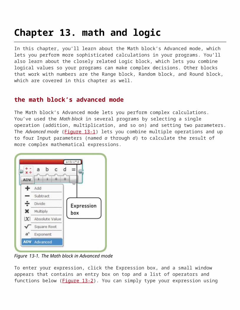
Chapter 13. math and logic In this chapter, you’ll learn about the Math block’s Advanced mode, which lets you perform more sophisticated calculations in your programs. You’ll also learn about the closely related Logic block, which lets you combine logical values so your programs can make complex decisions. Other blocks that work with numbers are the Range block, Random block, and Round block, which are covered in this chapter as well. the math block’s advanced mode The Math block’s Advanced mode lets you perform complex calculations. You’ve used the Math block in several programs by selecting a single operation (addition, multiplication, and so on) and setting two parameters. The Advanced mode (Figure 13-1 ) lets you combine multiple operations and up to four Input parameters (named a through d) to calculate the result of more complex mathematical expressions. Figure 13-1. The Math block in Advanced mode To enter your expression, click the Expression box, and a small window appears that contains an entry box on top and a list of operators and functions below (Figure 13-2 ). You can simply type your expression using
Transcript of magbuhatrobotics.files.wordpress.com€¦ · Web viewbecause the change made to the steering is...
Chapter 13. math and logicIn this chapter, you’ll learn about the Math block’s Advanced mode, which lets you perform more sophisticated calculations in your programs. You’ll also learn about the closely related Logic block, which lets you combine logical values so your programs can make complex decisions. Other blocks that work with numbers are the Range block, Random block, and Round block, which are covered in this chapter as well.
the math block’s advanced mode
The Math block’s Advanced mode lets you perform complex calculations. You’ve used the Math block in several programs by selecting a single operation (addition, multiplication, and so on) and setting two parameters. The Advanced mode (Figure 13-1 ) lets you combine multiple operations and up to four Input parameters (named a through d) to calculate the result of more complex mathematical expressions.
Figure 13-1. The Math block in Advanced mode
To enter your expression, click the Expression box, and a small window appears that contains an entry box on top and a list of operators and functions below (Figure 13-2 ). You can simply type your expression using common math operator symbols, or you can click one of the operators or functions in the list to add it to the current expression.

Figure 13-2. Entering the expression
SUPPORTED OPERATORS AND FUNCTIONS
Table 13-1 shows the list of supported operators, most of which you probably recognize. To use these operators, you can simply type the appropriate symbol, or you can select the operator from the list in the Expression box window.
Table 13-1. supported operatorsOperator
Description
+ Add
– Subtract or negate. 5–3 is subtraction. –a is negation.
* Multiply
/ Divide
^ Exponent. 2^3 means two raised to the third power, or 23.
% Modulo. Gives the remainder when the first number is divided by the second number. 5 % 2 is 1 because 2 goes into 5 twice with a remainder of 1.
Table 13-2 shows the list of supported functions, along with a brief description. Most of these deal with fairly advanced math, and we’ll use only a few of these functions in this book.
Table 13-2. supported functionsFunction
Description
floor() Rounds a value down to the nearest integer. floor(4.7) is 4, floor(4.1) is 4, and floor(-4.4) is -5.

Function
Description
ceil() Rounds a value up to the nearest integer. ceil(4.7) is 5, ceil(4.1) is 5, and ceil(-4.4) is -4.
round() Rounds a value to the nearest integer. round(4.7) is 5, round(4.1) is 4, round (-4.4) is -4, and round(-4.7) is -5.
abs() Gives the absolute value. abs(5) is 5, and abs(-5) is 5.
log() Gives the base 10 logarithm of a value.
ln() Gives the natural logarithm of a value.
sin() Gives the sine of an angle. All the trigonometric functions work in degrees.
cos() Gives the cosine of an angle.
tan() Gives the tangent of an angle.
asin() Gives the arcsine of an angle.
acos() Gives the arccosine of an angle.
atan() Gives the arctangent of an angle.
sqrt() Gives the positive square root of a value. sqrt(16) is 4.
Clicking a function in the list adds the function name and an opening parenthesis; then you need to enter the value that you want to perform the function on, followed by a closing parenthesis. For example, if you want to round the a parameter to the nearest integer, click the Round item so that round( appears. Then type a) (see Figure 13-3 ).

Figure 13-3. Entering an expression
THE MODULO OPERATOR
The modulo operator (%) gives the remainder when one number is divided by another. For example, 7 % 4 is 3, because 4 goes into 7 once with a remainder of 3. (The expression 7 % 3 is read “seven mod three”). This operator has some properties that make it very useful in computer programming.
Table 13-3 shows the result of the expression a % 3 for increasing values of a. Notice that the result starts at 0, increases to 2, and then starts at 0 again. The modulo operator is useful when you want a value to increase but then reset to a starting value each time it reaches a certain point. We saw this situation is Chapter 12 with the ScrollDisplay My Block, where the row starts at 0, increases to 11, and then goes back to 0. Figure 13-4 shows the part of the ScrollDisplay block that increases the row number, checks to see if it has reached 12, and then stores the new value. The value coming into the Math block from the left is the previous row value.
Table 13-3. the behavior of the modulo operatora a % 3
0 0
1 1
2 2
3 0
4 1
5 2
6 0
7 1
By using a Math block in Advanced mode and the modulo operator, we can accomplish the same thing with just two blocks (Figure 13-5 ). The expression (a + 1) % 12 adds 1 to a (which is the previous row number) and then gives the remainder when that value is divided by 12. So the row number starts at 0, increases to 11, and then returns to 0, just like in the original code.
MATH BLOCK ERRORS
If you enter an expression that the Math block can’t calculate properly, it produces an error. The Math block responds to different errors in different ways, and these errors can cause problems when you pass the Math block result to other programming blocks.
You can check for Math block errors by looking at the value on the data wire coming out of the block, or by showing the value on the EV3 screen using a Display block. For example, if you try to divide a number by 0, then the data wire coming from the Math block will show Infinity, as in Figure 13-6 , and will be printed on the EV3 display as “Inf”.

Figure 13-4. ScrollDisplay blocks for computing and saving the next row number
Figure 13-5. Computing and saving the next row number with two blocks
Figure 13-6. Math block error on the data wire when dividing by 0
Figure 13-7. Math block error on the data wire when taking the square root of a negative number
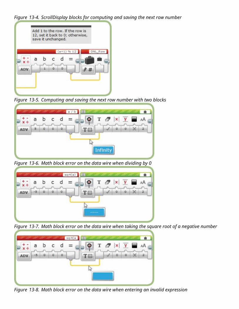
Figure 13-8. Math block error on the data wire when entering an invalid expression
Another common error occurs when you try to take the square root of a negative number. This produces a special Error value, which is displayed as ---- on either a data wire or the EV3 screen (see Figure 13-7 ). Similarly, if you enter an expression that’s missing a value or a parenthesis and can’t be evaluated, such as sqrt(a, or a + b*), the value on the data wire might appear blank, as it does in Figure 13-8 , and will appear on the display as “----”.
Using the value as an Input parameter to a block often gives strange results. For example, if you use the square root of a negative number for the Move Steering block’s Power parameter, the block acts as if the Power is set to 100. The same value used for the Duration in degrees makes the block behave as if you set the parameter to 0. Using the value for the Steering parameter causes the two motors to oscillate back and forth, a behavior that doesn’t correspond to any Steering value. Keep an eye out for these Error values because they can cause bugs.
a proportional LineFollower
In this section, we’ll turn back to our LineFollower program and use an advanced Math block to improve how the program adjusts the robot’s steering. The part of a line-follower program that adjusts the steering based on sensor readings is called a control algorithm. Improving the control algorithm makes the TriBot move more smoothly and follow lines with tighter turns.
The control algorithm developed in Chapter 6 and reworked in Chapter 9 (see Figure 13-9 ) is called a three-state controller because the program does one of three things based on the sensor reading: go straight, turn left, or turn right. The main problem with this method is that when the robot needs to turn, it always turns the same amount; whether the robot encounters a sharp or gentle turn, it uses the same fixed Steering value.
It would be better if the Steering value depended on the sharpness of the line, with gradual steering for straighter curves and sharp steering for sharper corners. This makes the program respond more quickly to changes in the direction of the line while still moving smoothly when the line is straight. This approach is called a proportional controller because the change made to the steering is proportional to, or directly related to, the robot’s distance from the edge of the line.
A proportional controller changes a control variable (in this case, the steering direction) based on a Target value and an Input value. In our case, the Input value is the reading from the Color Sensor. The Target value is the Color Sensor reading when the sensor is directly over the edge of the line. We determined this value back in Chapter 6 by taking the average of the Color Sensor readings with the TriBot off the line and centered over the line, which in my case was 52.

The difference between the Target value and the Input value is called the Error value. You can think of the Error value as the difference between where we want the robot to be and where it actually is. We multiply the Error value by the Gain value to get the Steering value. The Gain value determines how quickly the robot reacts to changes in the Error value. A smaller gain makes the robot move slowly, which means that it might not react quickly enough for tight turns, but results in less side-to-side motion when the line is fairly straight. A larger Gain value means a quicker reaction but can cause jerkier motion. Selecting the Gain value is called tuning the controller and usually involves some trial and error.
Figure 13-9. Three-state controller from the LineFollower program in Chapter 9
These are the equations for the Error value and Steering value:
Error value = Target value – Sensor reading Steering value = Error value × Gain value
We can combine these two expressions into (Target – Sensor Reading) × Gain and use a single Math block in Advanced mode to calculate the Steering value. Two of these values (the Target value and the Gain value) are constants, and in the program, we’ll use Constant blocks to supply the values to the Math block—this makes them easier to adjust. Changing the value shown by a Constant block requires fewer mouse clicks and is less error prone than changing the expression in the Math block.
The complete program is shown in Figure 13-10 . I set the Gain value to 0.7, which works well for my test line. Try different values to see what works best for your setup. These are the Input parameters to the Math block:

a The Color Sensor reading
b The Target value
c The Gain value
Using these parameters, the expression for the Steering value as described in the previous paragraph would be (b – a) × c. However, that expression yields values that steer in the opposite direction from the previous LineFollower program. (This would keep the robot on the right side of the line, instead of the left side like our earlier program did.) To make this more consistent with previous versions, I changed the sign of the result by making the expression –(b – a) × c.
Test this program with your own Target value and Gain value. You should be able to get a result that works better than the three-state LineFollower program.
EV3 timers
In the next program, you’ll use EV3 timers. The EV3 has eight built-in timers that act like stopwatches. You can use an EV3 timer to tell you how long your program has been running or to measure how long it takes the robot to perform a particular task. Typically, you reset the timer to 0 before beginning a task, and then read the timer when the task is complete. Notice that this is similar to how we’ve used the Rotation Sensor and Gyro Sensor in some of our programs—you can think of a timer as simply a time sensor.
Because the EV3 has eight timers, you can perform several timing tasks within the same program, for a variety of purposes. Here are a few ideas:
Time how long it takes your entire program to run, and use that information to compare different approaches. For example, you might measure how long it takes your robot to solve a maze using different programs and then use that information to choose the faster solution.
Time parts of your program to see whether you can speed up certain sections.
Use timers to make your program perform a periodic action.
For example, as part of an experiment, you could use a timer to read a sensor every 10 seconds over a period of 5 minutes.
Use a timer to limit how long you wait for a sensor to reach an expected Target value. This technique can help you avoid situations where your program stops working completely if something unexpected happens.

Figure 13-10. A proportional LineFollower programCHALLENGE 13-1
The GyroTurn program introduced in Chapter 5 has the TriBot make a quarter-turn by moving until the Gyro Sensor reads 90. This works well if the robot moves slowly and less well when it moves quickly. Improve on this by using the Gyro Sensor reading to control the speed, making the robot move more quickly when far from the end of the turn and slowing it down as it gets close to the target. This lets the TriBot make an accurate quarter-turn quickly, completing it in a second or two rather than the several seconds it takes at a constant, slow speed. Keep the TriBot from spinning too slowly by making sure that the Math block always gives some minimum value.
HINT
10 + (Target – Sensor reading) × Gain will always be at least 10 if the target is greater than or equal to the reading (and the gain is positive).
Timers can be selected from the Sensor list of the Wait, Switch, and Loop blocks. You can also control a timer using the Timer block, which appears on the Sensor palette. The Timer block (Figure 13-11 ) has three modes: Measure mode reads the current value of the timer (in seconds), Compare mode compares the value with a threshold and gives a Logic value result, and Reset mode resets the timer to 0. The block also has a parameter to select which of the eight timers to use.
Figure 13-11. The Timer block

the DisplayTimer program
The DisplayTimer program combines the power of the Math and Timer blocks to show a running timer on the EV3 screen. The program takes a reading from the Timer block and displays it in the typical minutes:seconds format; for example, 0:03 for three seconds, and 2:15 for two minutes and fifteen seconds. The program uses a Loop block to keep running until you stop it, and each time through the loop, a Timer block reads the timer and the new value is displayed.
Note that the Timer block reads out fractional values, such as 7.46 or 11.038, and the program displays those fractions as well (2:15.947). But to keep the discussion of this program simple, I’ll use whole numbers in any examples.
SPLITTING THE TIMER READING INTO MINUTES AND SECONDS
In this program, we take the reading from the Timer block and divide it into minutes and seconds. For example, if the Timer block reading is 127 seconds, we want to display this as 2 minutes and 7 seconds. We can do this with two simple formulas:
Seconds = Timer reading % 60
Minutes = (Timer reading – seconds) / 60
To calculate how many seconds to display (between 0 and 59), we take the remainder of the Timer block reading divided by 60. So when the Timer block reading is 127, we get 7, because 127 % 60 is 7.
Subtracting the number of seconds from the Timer block reading gives us a value that is a multiple of 60. Using the same example, 127 – 7 is 120. Dividing this value by 60 gives us the number of minutes, because there are 60 seconds in a minute.
Figure 13-12 shows the first part of the program. The Timer block reads the elapsed time and passes the value to the two Math blocks. The Math blocks each use Advanced mode to calculate the number of seconds and minutes to display. The block to calculate the number of seconds needs to come first because its result is used by the other Math block.
BUILDING THE TEXT TO DISPLAY
The next step is to take the minutes and seconds values, which are numbers, and combine them with a colon (:) to create a Text value in the form minutes:seconds. We could send the minutes and seconds values straight to a Text block to combine them, but there is one problem: If the number of seconds is less than 10, then the result won’t be correct. For example, if the number of minutes is 2 and the number of seconds is 7, then the Text block would generate 2:7 instead of 2:07. Before we send values to the Text block, we have to add a leading 0 to the Seconds value when it’s less than 10.
Figure 13-13 shows the code that constructs the correctly formatted Text value when the number of seconds is less than 10, along with the two Math blocks that supply the number of minutes and seconds. The program uses a Compare block to check if the seconds value is less than 10. The Switch block’s true case uses a Text block to add a 0 to the number of seconds and passes the result out of the Switch block to another Text block, which combines it with the number of minutes and a colon to generate the formatted value.

Figure 13-12. Turning the elapsed time into minutes and seconds
Figure 13-13. Adding a 0 if the number of seconds is less than 10
The final Text block now gives the correct value, 2:07, when the number of minutes is 2 and the number of seconds is 7.
What happens when the number of seconds isn’t less than 10? The false case of the Switch block is used, and we want to pass the value to the final Text block unchanged, so we can just draw a data wire from the block input plug directly to the block output plug, as shown in Figure 13-14 .
Figure 13-14. Passing the value out of the Switch block as a Text value
Notice that the data wire going into the Switch block contains a Numeric value from the Math block, which explains why it’s yellow. The data wire coming out holds a Text value (this plug was created by the Text block

inside the true case), which explains why it’s orange. When you build this program, be sure to fill in the true case first so that you get an orange Text output plug going out of the Switch block. If you fill in the false case first (passing the Numeric data wire through to the next block), this would create a yellow Numeric output plug, and then you wouldn’t be able to connect the data wire from the Text block in the true case to that plug. Remember, you can connect Numeric values to a Text plug (and the data type will convert automatically), but you can’t connect a Text value to a Numeric plug.
The final part of the program is a Display block to show the result of the final Text block on the EV3 screen (Figure 13-15 ). I’ve set the Row parameter to 4 because the text is a little easier to see when it’s closer to the middle of the screen.
Run the program and you should see the Time value counting up. Let the timer run for at least a minute so you can make sure it does the right thing when the number of seconds is less than 10, when the number of seconds is greater than 10, and when the minute should change from 0 to 1. The display will include three digits after the decimal point, and these digits will change very quickly. You’ll see how to hide or truncate those fractional values in the next section using the Round block.
Figure 13-15. Displaying the Time value
the round block
The Round block (Figure 13-16 ) gives you an easy way to round numbers. The four modes correspond to different ways you may want the number rounded. To Nearest rounds the value to the nearest integer, Round Up rounds the value up to the next largest integer, and Round Down rounds the value down to the next-smallest integer. These three modes do the same thing as the Math block’s round, ceil, and floor functions (available in Advanced mode).
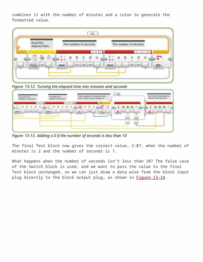
Figure 13-16. The Round block
Table 13-4 compares the results given by the three modes for some sample Input values. Notice that if the Input value is an integer, then all three modes pass the value along unchanged. The way the Round Up and Round Down modes work with negative numbers is a little counterintuitive but makes sense once you walk yourself through it; for example, since -4 is larger than -5, -4.2 rounds up to -4 and rounds down to -5.
Table 13-4. round block mode comparisonInput To Nearest Round up Round Down
4.0 4 4 4
4.2 4 5 4
4.5 5 5 4
4.7 5 5 4
-4.2 -4 -4 -5
-4.5 -5 -4 -5
-4.7 -5 -4 -5
The Round block’s Truncate mode has an additional parameter, Number of Decimals, which allows you to set how many digits to keep after the decimal point (see Figure 13-17 ). Any digits after the number you specify are eliminated (no rounding takes place).

Figure 13-17. The Round block’s Truncate mode
To make the DisplayTimer program show only one digit after the decimal point, add a Round block in Truncate mode after the Timer block. Be sure to connect the result of the Round block to the a Input parameter of both Math blocks (Figure 13-18 ). If you prefer to only show a whole number of seconds, set the Round block’s Number of Decimals parameter to 0.
Figure 13-18. Truncating the elapsed Time valueCHALLENGE 13-2
Create a TimeToText My Block from the blocks shown in Figure 13-14 . The My Block should take the elapsed Time value as an Input parameter and give the formatted Text value as an Output parameter.
the random block
Another math-related block on the Data Operations palette is the Random block, shown in Figure 13-19 . A die is used for the picture on the Random block, and like a die, the Random block generates random numbers, which you can use to create robotic games or to add some randomness to your robot’s behavior. Often a robot that is a little unpredictable can be more interesting and have more personality.

Figure 13-19. The Random block
With the Random block in Numeric mode, you can set the Lower Bound and Upper Bound parameters, and the block will generate an integer value between the two bounds. The default bounds are 1 and 10, giving an Output value that can be as small as 1 or as large as 10. You can change the range to suit your program; for example, to create a virtual die, you would set the Lower Bound to 1 and the Upper Bound to 6.
In Logic mode (Figure 13-20 ), the block generates a random Logic value (true or false) based on the probability you specify. The Probability of True parameter, between 0 and 100, determines how often the result will be true. For example, 80 means that there is an 80 percent chance that the result will be true and a 20 percent chance that the value will be false.
Figure 13-20. The Random block in Logic modeCHALLENGE 13-3
The DisplayNumber My Block (from Chapter 12 ) shows numbers using up to three decimal places. Add a parameter to specify the number of decimal places to round the value to before displaying it. The Round block’s Truncate mode doesn’t help here because we want the number rounded, not truncated. To Nearest mode alone also won’t do the trick because it only rounds to the nearest integer.
HINT
Say the number is 34.567 and we want it rounded to two decimal places so that the EV3 screen shows 34.57. Here’s one way to accomplish this:
1. Multiply 34.567 by 10^2 to get 3456.7. (Notice that the exponent is the same as the number of decimal places we’re interested in.)
2. Round the value, which gives us 3457.3. Divide 3457 by 10^2 to get 34.57.
adding a random turn to BumperBot
In this section, you’ll make a small change to the BumperBot program to make it a little more interesting. Recall that when the TriBot bumps into something, it backs up and turns in a different direction. The distance the robot turns doesn’t need to be any particular value; you simply want to have the robot point in a new direction. You can use a Random block to control the distance the robot turns, which will make the program less predictable.
You can start by copying the latest version of the Bumper-Bot program from your Chapter 6 project to your Chapter 13 project. Figure 13-21 shows the part of the BumperBot program that you need to change. This is the code that runs after the Touch Sensor is pressed. The first group of blocks makes the robot back up, and the final Move Steering block turns the robot.

Right now, the Move block is set to move 225 degrees. To make the turn less predictable, add a Random block before the Move Steering block to control how much the robot turns. Then set the range of values that the Random block can generate. The original program used 225 degrees, which turns the robot a little more than a quarter-turn. I’ll use 200 degrees for the Lower Bound and 2000 for the Upper Bound. With these values, the robot sometimes turns quickly and starts off again, and sometimes spins in place for a while before resuming its journey around the room. Figure 13-22 shows this part of the program with these changes made.
Figure 13-21. Backing up and turning around
Figure 13-22. Turning a random distance
Run the program with these changes, and the TriBot should vary the amount it turns after bumping into something.
the logic block

Many of the programs presented so far make decisions that involve a single condition, usually comparing the value from a Sensor to a Target value, with the result (either true or false) used in a Switch or Loop block. To put it another way, the programs are asking simple questions like “Is the Touch Sensor pressed?” or “Is the reading from the Color Sensor less than 50?”
The Logic block lets you combine multiple conditions, allowing your program to make more complex decisions. This lets your program ask questions like “Is the Touch Sensor pressed and the Color Sensor reading greater than 50?” You can find the Logic block, shown in Figure 13-23 , with the other math-related blocks on the Data Operations palette.
Figure 13-23. The Logic block
Figure 13-24. Moving forward until the Touch Sensor is pressed
The Logic block supports four operations: And, Or, XOR, and Not. Here’s how each operation works:
And. The result of the And operation will be true only if both Input values are true. If either Input value is false, then the result will be false.
Or. The result of the Or operation will be true if either Input value is true or if both Input values are true. The result will be false only if both Input values are false.
XOR. XOR is an abbreviation for Exclusive Or. This is similar to the Or operation except that the result is false if both Input values are true. This is the way the word or is often used in English: If your mother tells you that you can have ice cream or candy, she probably doesn’t mean you can have both; she expects you to pick one or the other.

Not. This operation only takes one Input value and generates the opposite value. If the Input value is true, then the Output value will be false, and if the Input value is false, then the Output value will be true.
Table 13-5 shows a table that lists all the possible Input values and the result for each operation. (This kind of table is called a truth table.) Note that the result of the Not operation depends only on the Input a value.
Table 13-5. truth table for the logic blockInput a Input b Or And XOR Not
False False False False False True
False True True False True True
True False True False True False
True True True True False False
adding some logic to BumperBot
In this section, you’ll make a change to the BumperBot program using the Logic block. Recall that the program keeps the TriBot moving forward until it runs into something. What if you want to limit how long the robot moves forward, perhaps to keep it from wandering too far? You’ll change the program so that the TriBot stops and turns around if it bumps into something or if it moves forward for more than 20 seconds.
Figure 13-24 shows the code that moves the TriBot forward. The Move Steering block starts the TriBot moving, and it keeps going until the Loop block ends when the Touch Sensor is pressed.
How can you tell whether the robot has traveled for more than 20 seconds? You can use a Timer block to reset the timer before starting to move and then use another Timer block within the loop to tell when 20 seconds have passed.
The Loop block can be configured to check the Touch Sensor or the Timer, but it can’t use both. To make the loop stop when either condition is true, you need to check both conditions, combine the results using a Logic block, and use the result of the Logic block to repeat or exit the loop. I’ll take you through these changes step by step.
1. Add a Timer block to the left of the Move Steering block, and set the mode to Reset (Figure 13-25 ).
Figure 13-25. The placement of the Timer block

Figure 13-26. Exiting the loop if 20 seconds have passed or the Touch Sensor is pressed
Figure 13-27. The Range block2. Add a Timer block after the Switch block. Set the mode to Compare Time and the Threshold parameter
to 20.3. Add a Touch Sensor block after the Timer block, and set the mode to Compare State.4. Add a Logic block to the right of the Touch Sensor block, and set the mode to Or.5. Draw a data wire from the Touch Sensor block’s Compare Result output to the Logic block’s a input.6. Draw a data wire from the Timer block’s Compare Result output to the Logic block’s b input.7. Select the Loop block, and change the mode to Logic.
8. Draw a data wire from Logic block’s Result output to the Loop block’s Until True input.
Figure 13-26 shows the program with these changes.
Now when you run the program, the TriBot should go forward for a maximum of 20 seconds. If it doesn’t bump into something within that time, it should turn and go off in a different direction.
the range block
The final math-related block is the Range block, which determines whether a number is inside or outside a range of numbers. The block has three parameters: the Test value (which you’ll usually supply with a data wire) and the Lower and Upper Bounds of the range you’re interested in.
The Range block has two modes: Inside and Outside (Figure 13-27 ). In Inside mode, the block asks “Is the test value inside the range (between the lower and upper limit)?” In Outside mode, the block asks “Is the test

value outside the range (less than the lower limit or greater than the upper limit)?” If the Test value equals the Upper or Lower Bound, then it’s considered to be inside the range.
the TagAlong program
The TagAlong program uses the Range block to make the TriBot follow you, staying a small distance behind, as you move across a room. This is a simple program that only moves the TriBot forward or backward. (It won’t follow you if you move to the side.) The program uses the Infrared Sensor and the Range block to see if the robot is within the desired range. If the robot is out of range, then a Move Steering block moves it forward or backward by using the Infrared Sensor reading to set the Power parameter. If the robot is within the desired range, the motors are stopped.
The program is shown in Figure 13-28 . Let’s go through the blocks one at a time to explain exactly how this program works.
Loop block. Keeps the program running until you stop it. Infrared Sensor block Uses Measure - Proximity mode to read the distance to an object in front of the robot (which is you!).
Range block. Checks whether the Infrared Sensor reading is outside the range. I set the range to 40–60, which keeps the robot reasonably close. The result is true if the reading is less than 40 or greater than 60, and it’s false otherwise.
Figure 13-28. The TagAlong program Switch block. The true case is used when the robot is out of range and needs to move. The Power
parameter of the Move Steering block is calculated by subtracting 50 from the Infrared Sensor reading. 50 is used because it’s halfway between 40 and 60. So if the reading is over 60, the Power parameter

ends up being at least 10, and the robot moves forward. If the reading is less than 40, the Power parameter ends up being -10 or less, and the robot moves backward.
The false case of the Switch block is used when the robot is in the correct range, with the Sensor reading between 40 and 60. In this case, a Move Steering block is used to stop the motors.
NOTE
If you’re using the Ultrasonic Sensor, use an Ultrasonic Sensor block in Measure - Distance Inches mode. Set the Range block bounds to 12 and 24 and the b parameter of the Math block to 18 (the average of 12 and 24).
Run this program and the TriBot should move forward and backward as you move away from or toward it.
the GyroPointer program
The GyroPointer program is a variation of the TagAlong program that keeps the TriBot pointing in the same direction while you spin the robot on a rotating platform. If you are using the EV3 Home Edition and don’t have a Gyro Sensor, read this section and try applying the concepts in Challenge 13-4.
To test this program, place the TriBot on a turntable (or a lazy Susan, rotating stool, or some other rotating surface) and slowly rotate the turntable while the program runs. The TriBot spins to keep pointing in the general direction in which it started.
Figure 13-29 shows the program. It has the same basic structure as the TagAlong program with a few notable changes:
A Gyro Sensor block is used instead of the Infrared Sensor block.

Figure 13-29. The GyroPointer program
The parameters of the Range block check that the sensor reading is between -10 and 10. The reading at the start of the program will be 0, so this range keeps the robot pointing close to where it starts.
The Math block’s result is connected to the Move Steering block’s Steering parameter rather than the Power parameter. To make the TriBot spin, we want this setting to be either -100 or 100; otherwise, the robot will move forward as well as turn.
The Math block multiplies the sensor reading by -10. If the sensor reading is less than -10, the result will be more than 100, and the Move Steering block will treat the value as 100. If the sensor reading is more than 10, the result will be less than -100, and the Move Steering block will treat the value as -100.
When you run this program, the TriBot sits motionless until you move the turntable at least 10 degrees (in either direction). Then the Tribot spins to keep facing the direction in which it started. Move the turntable in one direction and then the other, and the TriBot should adjust to keep pointing in the same general direction.
CHALLENGE 13-4
If you have the EV3 Home Edition, use the Infrared Sensor and Infrared Remote to create a RemotePointer program that works the same way as the GyroPointer program. The program should spin the TriBot so that it keeps pointing in the general direction of the Infrared Remote by using the beacon heading to control the Move Steering block.
further exploration
Try these activities for more practice with math-related blocks:

1. Write a CountDown program that shows the time counting down from two minutes on the EV3 screen. The Loop block should exit when the time gets to zero.
2. Combine the TagAlong and RemotePointer programs to make a program that will maintain both its distance and direction. The resulting program should make the robot follow the Infrared Remote around a room.
3. Use the Random block to create a MagicEightBall program. When you ask a question and trigger the robot (such as by pressing the Touch Sensor), the robot should select an answer randomly from several possible answers. Use the Display block to show the answer on the screen. You can also use the Sound Editor tool to record your own answers and the Sound block to play them.
4. This activity uses some knowledge of trigonometry; feel free to skip over this one if you haven’t reached that level of mathematics yet. The sine function starts at 0 and oscillates between 1 and -1, so if you graph this function, it creates a snake-like curve. You can make the robot follow a winding, serpentine path by using the sine function to control how the robot steers. Create a Slither program using a timer and a Math block that uses the sine function to control the Steering parameter on a Move Steering block. Hint: Using sin(Elapsed time) directly won’t be very interesting because it takes 6 minutes (360 seconds) for the value to go from one extreme to the other, and the value only goes between -1 and 1. However, if you multiply the elapsed time by 10, the entire range will be covered in only 36 seconds, and if you multiply the result by 50, the Steering value will oscillate between 50 and -50.
conclusion
In this chapter, you learned how use blocks that work with numbers and logic. The Math block’s Advanced mode gives you all the power you need to calculate complex equations, which allowed you to improve the LineFollower program by using a proportional controller. You also learned about the modulo operator and saw it in action in the DisplayNumberNextLine My Block and the DisplayTimer program.
The Logic block lets you write programs that make complex decisions, such as combining the input from multiple sensors. The Range block gives you a convenient way to perform the common operation of testing a value to see whether it’s in a certain range. The other block introduced in this chapter was the Random block, which you can use to add a little unpredictability to your programs and personality to your robots.