
€¦ · Web view · 2014-09-26These test are generally described in the manufactures service...
40
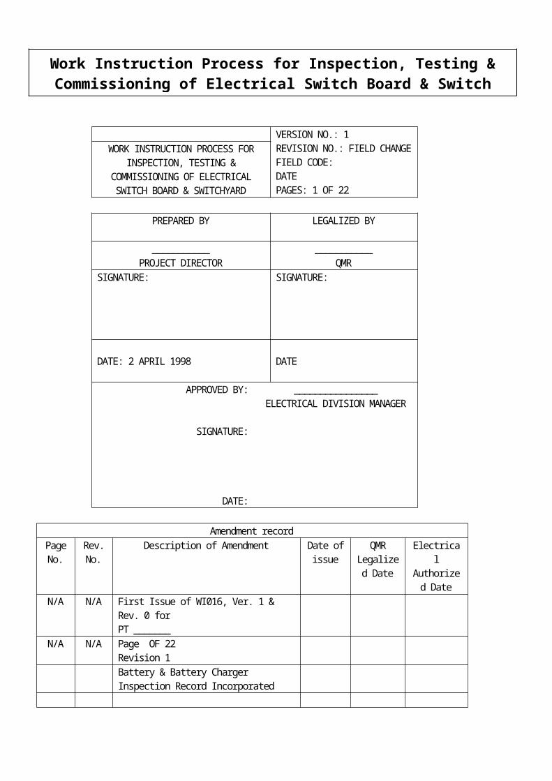
VERSION NO.: 1 REVISION NO.: FIELD CHANGE FIELD CODE: DATE PAGES: 1 OF 22 WORK INSTRUCTION PROCESS FOR INSPECTION, TESTING & COMMISSIONING OF ELECTRICAL SWITCH BOARD & SWITCHYARD PREPARED BY LEGALIZED BY ___________ PROJECT DIRECTOR ___________ QMR SIGNATURE: SIGNATURE: DATE: 2 APRIL 1998 DATE APPROVED BY: SIGNATURE: DATE: ________________ ELECTRICAL DIVISION MANAGER Amendment record Page No. Rev. No. Description of Amendment Date of issue QMR Legalize d Date Electrica l Authorize d Date N/A N/A First Issue of WI016, Ver. 1 & Rev. 0 for PT _______ N/A N/A Page OF 22 Revision 1 Battery & Battery Charger Inspection Record Incorporated Work Instruction Process for Inspection, Testing & Commissioning of Electrical Switch Board & Switch
Transcript of €¦ · Web view · 2014-09-26These test are generally described in the manufactures service...
VERSION NO.: 1REVISION NO.: FIELD CHANGEFIELD CODE: DATEPAGES: 1 OF 22
WORK INSTRUCTION PROCESS FOR INSPECTION, TESTING &
COMMISSIONING OF ELECTRICAL SWITCH BOARD & SWITCHYARD
PREPARED BY LEGALIZED BY
___________PROJECT DIRECTOR
___________QMR
SIGNATURE: SIGNATURE:
DATE: 2 APRIL 1998 DATE
APPROVED BY:
SIGNATURE:
DATE:
________________ELECTRICAL DIVISION MANAGER
Amendment recordPage No.
Rev. No.
Description of Amendment Date of issue
QMR Legalized
Date
Electrical Authorized
DateN/A N/A First Issue of WI016, Ver. 1 & Rev. 0 for
PT _______N/A N/A Page OF 22
Revision 1Battery & Battery Charger Inspection Record Incorporated
DISTRIBUTION TO:
1) ALL MANUAL HOLDER
Work Instruction Process for Inspection, Testing & Commissioning of Electrical Switch Board & Switch Yard
WORK INSTRUCTION PROCESS FOR INSPECTION, TESTING & COMMISSIONING OF ELECTRICAL SWITCH BOARD & SWITCH YARD
PURPOSE
SCOPE
RESPONSIBILITIES
DEFINITIONS
PROCEDURES
5.1 GENERAL5.2 POLARITY CHECKS5.3 RATIO CHECKS5.4 MAGNETIZATION CURVE5.5 VOLTAGE TRANSFORMER TEST5.6 RATIO CHECK5.7 PHASING CHECK5.8 SECONDARY INJECTION5.9 HI-POT TESTING USING FERRANTI HI-POT SET5.10 HI-POT TESTING USING BIDDLE HI-POT TEST SET5.11 EARTH RESISTANCE TEST (ET5) TO AS30005.12 DUCTER TESTING (SWITCH GEAR)5.13 BLOCK DIAGRAM OF COMMISSIONING HV SWITCH YARD5.14 BLOCK DIAGRAM OF COMMISSIONING HV SWITCH BOARDS5.15 MIDOS RELAY TYPES5.16 COMMISSIONING CHECK LIST
QUALITY RECORDS
Work Instruction Process for Inspection, Testing & Commissioning of Electrical Switch Board & Switch Yard
1.0
2.0
3.0
4.0
5.0
6.0

1.0 PURPOSE
1.1 To ensure testing carried out in Switch Yards and Switch Boards is done so in a planned acceptable manner.
2.0 SCOPE
2.1 This procedure applied to the testing of all switch gear undertaken by PT ______ Technical Services Division except if otherwise directed by the Client.
3.0 DEFINITIONS
The Client Main Contractor
4.0 RESPONSIBILITIES
4.1 The Technical Services Supervisor is responsible for:
(a) Coordination of inspection activities(b) Ensuring test reports are sent out to clients.
4.2 Technical Services Technicians are responsible for carrying out tests as directed in accordance with these procedures, and recording the test or inspection results on the correct form.
5.0 PROCEDURES
5.1 General
5.1.1 All results of equipment tested shall be recorded on the relevant test sheet, refer Section 5.0, copies being in Procedures Manual PM2.
5.1.2 All equipment used for inspection and testing shall carry a current calibration sticker is not affixed, contact the Technical Services Supervisor.
Work Instruction Process for Inspection, Testing & Commissioning of Electrical Switch Board & Switch Yard

5.1.3 If any equipment should fail inspection and/or testing, the client will be notified at the time of testing or, if not available, at the earliest possible time.
5.1.4 A test report will be issued to the Client for all inspection and testing undertaken if the specified in the contract or on request from the Client.
5.2 Polarity Checks
Each current transformer should be individually tested to verified that the primary and secondary polarity markings are the same as drawings supplied by client.
At current transformer terminals in Protection/Metering Panel. The Protection/Metering Terminal identification is as follows:
C10 This is Red Phase over-current or earth fault protectionC30 This is Yellow Phase over-current or earth fault protectionC50 This is Black Phase over-current or earth fault protectionC70 This is Neutral over-current or earth fault protection
A10 or A110 This is Red Phase differential protectionA30 or A130 This is Yellow Phase differential protectionA50 or A150 This is Black Phase differential protectionA70 or A170 This is Neutral differential protection
D10 This is Red Phase meteringD30 This is Yellow Phase meteringD50 This is Black Phase meteringD70 This is Neutral Metering return
NOTE: The above identifications always starts with A, C or D but the numbers may be slightly different. The numbers always use 10, 30 and 50 but maybe the number is C110. This is done when there are several protection schemes on the same feeder.
Work Instruction Process for Inspection, Testing & Commissioning of Electrical Switch Board & Switch Yard

Method
Connect polarity test set as per drawing, Fig. 1, by pushing test button down, a positive flick on the meter should occur. If this does not occur follow check chart below.
FIGURE 1 POLARITY CHECK
Check list Meter Polarity Incorrect
1. Check drawing for correct P1-P2 directions
2. Check connection on polarity test set
NO FLICK ON METER
1. Open lines on C T Terminals
2. Check you have to correct numbers (ie C10 and C11)
Work Instruction Process for Inspection, Testing & Commissioning of Electrical Switch Board & Switch Yard
FIGURE 1 POLARITY CHECK
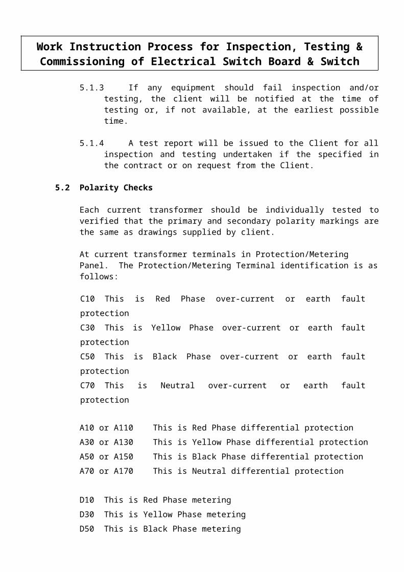
5.3 Ratio ChecksThis check is usually carried out to verify the ratio of the CT to the drawings. Current is passed through the primary conductors and measured by means of the test set ammeter or CT used in conjunction with the test set A1. The secondary current is measured on the ammeter A2 in Figure 2 and A2 + A3 in Figure 3.
FIGURE 2 CURRENT TRANSFORMER CHECKS (SINGLE PHASE)
Work Instruction Process for Inspection, Testing & Commissioning of Electrical Switch Board & Switch Yard
FIGURE 2 CURRENT TRANSFORMER CHECKS (SINGLE PHASE)

FIGURE 3 CURRENT TRANSFORMER CHECKS (TWO PHASES)
IMPORTANT: When injection of current is taking place make sure, if there is more than 1 CT in that Phase that the CT’s not in test are shorted out and not open circuit.
5.4 Magnetization Curve
Work Instruction Process for Inspection, Testing & Commissioning of Electrical Switch Board & Switch Yard
FIGURE 3 CURRENT TRANSFORMER CHECKS
(TWO PHASES)

This test is carried out when commissioning to,
1. verify the CT is manufactures specs,2. check that when the equipment has been assembled they have been wired
correctly, ie over-current and differential are correctly wired.
When checking aboard with metering, over-current and differential the knee point curve should be very low with saturation flux as low as 20-30V were as the over-current voltage will be around 120V to 180V. Differential CT’s have a knee point around 500V upwards.
V
Types of CT’s used,
Class 1 = Metering CT’sIOP50 = Over-current type CT’s005P2O = Differential type CT’s
Work Instruction Process for Inspection, Testing & Commissioning of Electrical Switch Board & Switch Yard
FIGURE 4 KNEE POINT OF CT
I
Knee Point of C.T. 50% increase in current to 10%
increase in voltage
FIGURE 4 KNEE POINT OF CT

FIGURE 5 TESTING CURRENT TX MAGNETISING CURVE
Work Instruction Process for Inspection, Testing & Commissioning of Electrical Switch Board & Switch Yard
FIGURE 5 TESTING CURRENT TX MAGNETIZING CURVE
METHOD
Several points must be checked on each CT. This is done through a variable transformer while the primary CT circuit remains open. See Figure 5. The magnetizing current is measured on the ammeter A and the secondary voltage using a voltmater. The applied voltage would be slowly raised until the magnetizing current is seen to rise rapidly (50% increase in current to 10% increase in voltage), for a small increase in voltage. This indicates the approximate knee point of the CT. The magnetizing current should be recorded using Technical Service sheets.
It is often found that the current transformer with a secondary rating of 1 ampere or less have a knee point voltage higher than the legal main supply. In this case a step up transformer may be required to obtain the necessary voltage to check the curve.
5.5 Voltage Transformer Tests
The voltage transformer polarity can be checked with the test described for the main current transformers, care must be taken to connect the battery supply to the primary winding, with the polarity ammeter connected to the secondary winding if the voltage transformer is of the capacitor type, then the polarity of the transformer at the bottom of the capacitor stack should be checked.
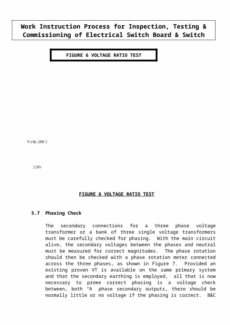
5.6 Ratio Check
This check is carried out on HV voltage transformers to verify the ratio is correct.
Method
As in Figure 6 22kV side of transformer is energized using 415V. Readings should be taken on LV side phase to phase to neutral. Taking the ratio into consideration the voltage on the secondary of a 22000V/110V transformer should be phase 2.08V and phase to neutral 1.20V.
Work Instruction Process for Inspection, Testing & Commissioning of Electrical Switch Board & Switch Yard
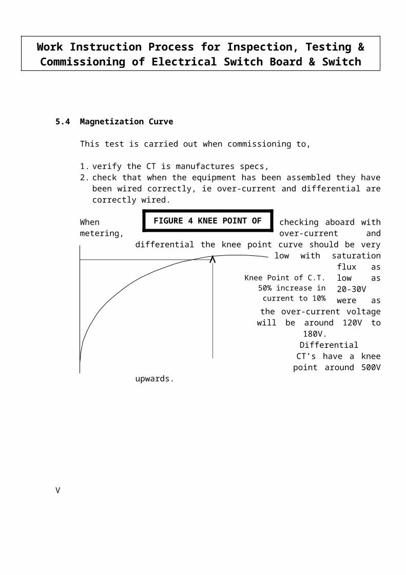
FIGURE 6 VOLTAGE RATIO TEST
5.7 Phasing Check
The secondary connections for a three phase voltage transformer or a bank of three single voltage transformers must be carefully checked for phasing. With the main circuit alive, the secondary voltages between the phases and neutral must be measured for correct magnitudes. The phase rotation should then be checked with a phase rotation meter connected across the three phases, as shown in Figure 7. Provided an existing proven VT is available on the same primary system and that the secondary earthing is employed, all that is now necessary to prove correct phasing is a voltage check between, both “A” phase secondary outputs, there should be normally little or no voltage if the phasing is correct. B&C phase should be checked also, this proves the system by means of secondary phasing checks.
Work Instruction Process for Inspection, Testing & Commissioning of Electrical Switch Board & Switch Yard
FIGURE 6 VOLTAGE RATIO TEST

FIGURE 7 TRANSFORMER PHASING CHECK
5.8 Secondary Injection
These test are generally described in the manufactures service manual for relays, but brief details are given below for the main types of protection relays.
Equipment
It is common practice to provide test blocks or test sockets in the relay circuits so that connections can readily be made to test without disturbing wiring. A later development was the test plug which can be used to plug into draw-out relay case or into test block nominated near to a non draw-out relay case.
Work Instruction Process for Inspection, Testing & Commissioning of Electrical Switch Board & Switch Yard
FIGURE 7 TRANSFORMER PHASING CHECK

When used with a draw-ou relay the multiple figures of the test plug are inserted between the contract stripes of the case and the draw-out chassis are normally spinning together to make firm contact.
Since the top and bottom contact or each test plug finger is separated by an insulation strip to relay circuits can be completely isolated from the switchgear wire when the test plug is inserted, ie is most important to remember, that the correct transformer shorting switches, will not be shorted links are fitted across all live side CT terminals of the test plugs before it is inserted. When the test plus is inserted in position all the test circuitry can now be connected to the isolated ‘Relay Side’ test plug terminals.
Withdrawing the test plug immediately restores the connections to the main current transformers and voltage transformers removed is the test connections and also the short circuits which had been applied to the main CT secondary circuits.
A recent development has been the testing facilities provided for the modular type case. The heavy current connectors at the extreme right hand side of the case are normally connecting the main A.C. and D.C. incoming supplies to the relay and hold open short circuiting switches provided in the case to prevent CT secondary circuits from being open circuited.
When these connections are removed, the relay is isolated and the main current transformer incoming connections are automatically short circuited.
A test plug may then be inserted so that secondary injection test can take place. As previously described for the draw-out case, care must be taken then inserting plug as the CT terminals are open circuited. As previously described CT terminals must have shorting links in before plug is inserted. The relay is now isolated for testing in the case of an MCGG63 (over-current and earth fault relay) terminals 13 and 14 must be linked, 15 and 16 must be linked this give the relay its supply. Care must be taken to make sure 13 is positive and 14 is negative at relay terminals.
Work Instruction Process for Inspection, Testing & Commissioning of Electrical Switch Board & Switch Yard

5.9 Hi-Pot Testing using Ferranti Hi-Pot Test Set
Cable testing as per AS 1026 & AS 1429
5.9.1 Insulation Test (Before)
For a XLPE cable, which is individually screened each core should be tested between screen and core. Results should be in the high Meg-ohms. Each test should be for 1 minute.
For cables which are not individually screened, each core should be tested to earth with the other cores at earth potential. Results should be in high Meg-ohms. Each test, should be 1 minute.
The above test should be carried out using test report number-------.
5.9.2 HV Test
(a) Core to Screen TestFor core to screen test, connect HV probe into negative output of test set. Connect HV prove to core under test, and earth to screen of cable. Turn on key switch, then HV switch. HV light should be on. With voltage control knob wound back fully anticlockwise, a micro switch should be heard operating. Slowly wind knob clockwise, observe voltage increase and milliamp meter. Once required voltage has been reached, time test for period specified. Discharge cores after each test, using discharge stick.
(b) Core to Core TestFor core to core testing, connect HV probes into negative and positive outputs of test set. Connect earth of test set to earth on cable. Connect probes to cores under test, making sure spare core is connected to positive output of test set. Turn on key switch, then HV switch, HV light should be on. With voltage control know wound back fully anticlockwise, a micro switch should be heard operating. Slowly wind know clockwise, observing voltage increase and milli-amp meter. Once required voltage has been reached, time test for period specified. Discharge cores after each test, using discharge stick.
Work Instruction Process for Inspection, Testing & Commissioning of Electrical Switch Board & Switch Yard
5.9.3 Insulation Test (After)
For a XLPE cable, which is individually screened, each core should be tested between screen and core. Results should be in the high Meg-ohms. Each test should be for 1 minute.
For cables which are not individually screened, each core should be tested to earth with the other cores at earth potential. Results should be in the high Meg-ohms. These test should be for 1 minute.
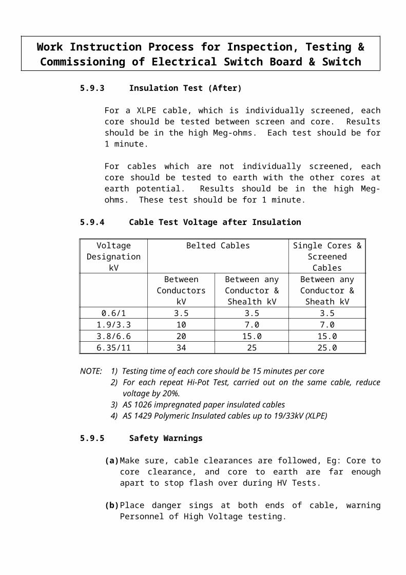
5.9.4 Cable Test Voltage after Insulation
Voltage Designation kV
Belted Cables Single Cores & Screened Cables
Between Conductors kV
Between any Conductor & Shealth kV
Between any Conductor & Sheath kV
0.6/1 3.5 3.5 3.51.9/3.3 10 7.0 7.03.8/6.6 20 15.0 15.06.35/11 34 25 25.0
NOTE: 1) Testing time of each core should be 15 minutes per core2) For each repeat Hi-Pot Test, carried out on the same cable, reduce
voltage by 20%.3) AS 1026 impregnated paper insulated cables4) AS 1429 Polymeric Insulated cables up to 19/33kV (XLPE)
5.9.5 Safety Warnings
(a) Make sure, cable clearances are followed, Eg: Core to core clearance, and core to earth are far enough apart to stop flash over during HV Tests.
(b) Place danger sings at both ends of cable, warning Personnel of High Voltage testing.
Work Instruction Process for Inspection, Testing & Commissioning of Electrical Switch Board & Switch Yard

(c) Place barriers around both ends of cable preventing Personnel from entering test area.
(d) If cables is in a situation where Personnel could come in contact with it, or if it would be safer to have someone at the open end, do so.
(e) Take time in carrying out test, as High Voltage test sets have the potential to KILL.
(f) Always discharge cables after each test.
5.10 Hi-Pot Testing using Biddle Hi-Pot Test Set
Cable testing as per AS 1026 & AS 1429
5.10.1 Insulation test of cable (Before)
For a XLPE cable which is individually screened, each core should be tested between screen and core. Results should be in the high Meg-ohms. Each test should be for 1 minute.
For cables which are not individually screened, each core should be tested to earth with the other cores at earth potential. Results should be the high Meg-ohms. Each test should be for 1 minute. The above test should be carried out using test report number -------.
5.10.2 HV Test
(a) XLPE Individually Screened Cables
Connect HV probe to cable. With foot switch in position and depressed, set dial to zero, this allows HV to be energized. Turn dial clockwise, observing kV and mili-amp meters, until required voltage is reached. Carry out test to all three cores individually. After each test discharge cores using discharge stick.
(b) Unbelted Cables
Connect HV probe to core. Short other cores to earth. With foot switch in position and depressed, set dial to zero, this allows HV to be energized. Turn dial clockwise observing kV and milli-amps meters, until required voltage is reached. Carry out test to all three cores individually. After each test discharge cores using discharge stick.
NOTE: FOLLOW WARNING GIVEN ON TESTING
Work Instruction Process for Inspection, Testing & Commissioning of Electrical Switch Board & Switch Yard

5.10.3 Insulation Test of Cables (After)
For a XLPE cable which is individually screened each core should be tested between screen and core. Results should be in the high Meg-ohms. This test should be for 1 minute.
For cables which are not individually screened each core should be tested to earth with the other cores at earth potential. Result should be in the high Meg-ohms. This test should be for 1 minute.
5.10.4 Cable Test Voltage after Installation
Voltage Designation kV
Belted Cables Single Cores & Screened Cables
Between Conductors kV
Between any Conductor & Shealth kV
Between any Conductor & Sheath kV
0.6/1 3.5 3.5 3.51.9/3.3 10 7.0 7.03.8/6.6 20 15.0 15.06.35/11 34 25 25.011/11 34 34.0 34.0
12.7/22 - 50.0 50.019/33 - 75.0 75.0
Note: 1. Testing time of each core should be 15 minutes per core.
2. For each repeat Hi-Pot test carried out on the same cable reduce voltage 20%.
3. AS 1026 impregnated paper insulated cables.
4. AS 1429 Polymeric insulated cables up to 19.33 kV (XLPE)
Work Instruction Process for Inspection, Testing & Commissioning of Electrical Switch Board & Switch Yard

5.10.5 Safety Warnings
(a) Make sure cable clearance are followed. Eg: Core to core clearances, and core to earth are far enough apart to stop flash over during HV tests.
(b) Place Danger signs at both ends of cable warning Personal of High Voltage testing.
(c) Place barriers around both ends of cable, preventing Personal form entering test area.
(d) If cable is in a situation were Personnel could come in contract with it, or if it would be safer to have someone at the open end, do so. Take your time in carrying out test as High Voltage test sets have the potential to KILL.
5.11 Earth Resistance Test (ET5) To AS3000
5.11.1 Normal Method of Test
Join terminal C1 an dP1 together connecting a lead to the electrode under test. The length of this lead should be kept to a minimum, as this will affect the electrode. P2 lead can be connected to electrode which should be between 15 and 25m from test point. C2 lead can be connected to an electrode 15 to 25 meters away form P2. This must be kept in a line so P2 can pick up the volt drop between electrode under test (C1) and C2.
5.11.2 Fall of Potential Method
Join terminals C1 and P1 together connecting a lead to the electrode under test. The length of this lead should be kept to a minimum, as this will affect the electrode resistance. Lead resistance can be deducted by running two leads for P1 and C1 to the electrode. P2 connection to spike should be 25m away from electrode under test. C2 should then be placed 25m from P2 in a straight line. After a test has been carried out at this point P2 should be moved about 3m either side of centre. If the first resistance is the same as the first reading, or close to it. The mean value is used as the earth resistance. If the readings are completely difference then the test using the 62 feet and 100 feet should apply.
Work Instruction Process for Inspection, Testing & Commissioning of Electrical Switch Board & Switch Yard

5.11.3 The 62% Rule for Single Earth Systems
It is normal, to carry out the measurement of electrode resistance by full of potential method! The 62% Rule involves positioning of potential spikes P and C at intervals of 62 feet and 100 feet. Connecting cables to earth tester to complete the current and voltage under test. To obtain a true reading, the current spike must be correctly placed in line with electrode under test. Since both electrode under test and C2 must be sufficiently apart to stop resistance are of both spikes overlapping.
Graphically it can be demonstrated that:
The true resistance of the electrode to be tested is equal to the measured resistance when the potential electrode is at a distance from the electrode. This should be equal to 62% of the distance from the earth electrode to the current electrode C2.
NOTE: This rule can only apply when all electrodes are in line and the earth is a single electrode, pipe or plate.
5.11.4 Test Procedure
(a) Check battery condition before leaving workshop.
(b) Connect instrument for test required as explained on previous pages.
(c) Set range switch to X1 and resistor dial to 010 (eg 10 ohms).
(d) Press the test button and watch galvanometer movement.
(e) If the deflection is (+) increase resistor dial to provide more resistance until pointer comes back to the center. Increase range switch if needed, (eg X10).
(f) If the deflection is (-) decrease resistor dial to reduce resistance, until pointer comes back to the center. Reduce range switch if required, (eg X0-01).
Work Instruction Process for Inspection, Testing & Commissioning of Electrical Switch Board & Switch Yard

(g) Resistance measured is reading on dials x range factor.
NOTE: Australian Standards required as follows:
(a) earthing HV and LV AS3000 Section 8.12
(b) Lighting protection systems AS1768 Section 3.11
5.11.5 Safety Precautions
All personnel involved in testing, should be warned of the voltage that can be generated by earth tester.
The maximum voltage can be up to 200 bolts AC.
5.12 Ducter Testing (Switch Gear)
5.12.1 Connect load to Ducter test set, BLACK on the outer side and RED on the inner. Select scale required, either micro-ohms or milli-ohms. Place probe on busbar under test keeping the ‘P’ on probe on the inside while testing. Wait until the reading settles then record on ____ test sheet.
5.12.2 Where applicable, results recorded should be checked against manufacturers specification (if available). All phases should be within 30-40 micro-ohms. Some judgment by the testing technician may be required under circumstances. Eg. Busbar, lengths are different Switch gear. This may alter results over three phases up to 30%.
Work Instruction Process for Inspection, Testing & Commissioning of Electrical Switch Board & Switch Yard
5.13 BLOCK DIAGRAM OF COMMISSIONING HV SWITCH YARD
5.14 BLOCK DIAGRAM OF COMMISSIONING HV SWITCH BOARDS
Work Instruction Process for Inspection, Testing & Commissioning of Electrical Switch Board & Switch Yard
5.15 MIDOS Relay Types
MAVS Check synchronising relayMBCH Biases differential protectionMBC1 Translay ‘S’ differential feeder protectionMBC2 Low impedance over-current relaysMCAG 11, 12 instantaneous over-current relaysMCAG 14 high stability circulating current delayMCAG 19, 39 instantaneous over-current and earth fault relayMCGG Over-current relays for phase and earth faultsMCHD Thermal replica relayMCHG Motor protection relayMCHN Motor protection relayMCND Negative sequence over-current relayMCRI Instantaneous over-current relayMCSU Sensitive earth fault relayMCTD Silicon rectifier and filter protection relayMCTH Transformer current inrush detectorMCT1 Local breaker back-up relayMGT1 Single pole directional relayMFAC High impedance differential relayMFVU21 Digital definite time frequency relayMHO1204 High speed pilot wire protectionMRSUO1 Rotor earth fault protection relayMRTP Supervision for AC pilot circuitsMSTZ02 Power supply unit (DC/AC converter)MSTZ03 Power supply unitMSTZ81 Power supply unit (current operated)MVAA Tripping and auxiliary relaysMVAJ Tripping and control relaysMVAW Interposing relayMVAX Trip circuit supervision relayMVGC Static voltage regulating control relayMVTC Inspection alarm and maintenance lockout relayMVTD Inverse time delayed voltage relayMVTP Bus bar supervision relayMVTRO1 Auto re-close relayMVTR51 Multi shot auto re-close relayMVTR52 Multi shot auto re-close relayMVTT14 15 digital time delay relays
Work Instruction Process for Inspection, Testing & Commissioning of Electrical Switch Board & Switch Yard

MVTU Define time delay voltage relaysMVTW Destablising/inter-tripping relaysMVUA Time delayed auxiliary and tripping relaysMWTU01 Reverse power relayMYTU Field failure relayMZTU Under impedance relay
5.16 COMMISSIONING CHECK LIST
SWITCHBOARD HV/MV :LOCATION:
YES NO1. Polarity test to current transformers2. Ratio test to current transformers3. Magnetisation curves to current transformers4. Polarity test to voltage transformers5. Ratio test to voltage transformers6. Set all protection relays7. Secondary injection of all protection relays8. Ducter test all connections (bus bar joints, etc)9. Ducter test all circuit breakers with breakers closed10. Secondary injection to prove metering11. High Pot Switchboard12. High Pot Circuit breakers13. Energise Switchboard14. Phase Rotation if required
SWITCH YARD HV :LOCATION:
YES NO1. Polarity test to CT’s2. Ratio test to CT’s3. Magnetisation curves to current transformers4. Polarity test to voltage transformers5. Ratio test to voltage transformers6. Set protection scheme (relay settings)7. Secondary injection of protection relays8. Ducter test to bus bars and connections
Work Instruction Process for Inspection, Testing & Commissioning of Electrical Switch Board & Switch Yard
YES NO9. Ducter test to bus bars and connections
10. Secondary injection to prove metering11. Function test to circuit breaker12. Energise switch yard and carry out phase rotation
6.0 QUALITY RECORDS
DOCUMENT SITE AMENDMENT
Form Description of Quality Record Filing Archives Retention
Responsible PersonLocation System
no Oil Dielectric Strength Test Record QC/DC
no Cable Tray Inspection Check List QC/DC
no Cable Pulling Inspection Check List QC/DC
no Megger Readings (Power, Control Wire & Cable)
QC/DC
no Megger Readings (Elect. Equipment Incl. Motors)
QC/DC
no Insulating Resistance Test Records (Rotation)
QC/DC
no Ground well Resistance Readings QC/DC
no Megger Reading (Transformer) QC/DC
no Switchgear Inspection Record QC/DC
no 380V Switch Board Inspection Record
QC/DC
no Motor Control Center Inspection Record
QC/DC
no Liquid Filled TR. Inspection Check List
QC/DC
no Pre-Commissioning of Power Transformer
QC/DC
no Neutral Grounding Resistor Inspection Record
QC/DC
no Battery & Battery Charger & UPS Inspection Record
QC/DC
no Replacement of Field Control Station Test Record
QC/DC
no Internal Lighting Check Sheet QC/DC
Work Instruction Process for Inspection, Testing & Commissioning of Electrical Switch Board & Switch Yard

DOCUMENT SITE AMENDMENT
Form Description of Quality Record Filing Archives Retention
Responsible PersonLocation System
no Underground Conduit Inspection Check List
QC/DC
no Above Ground Conduit Inspection Check List
QC/DC
no Overall Completion of Earthing Grid QC/DC
no Earthing Riser Layout QC/DC
no Earthing Wire Layout QC/DC
no Cadweld Connection of Earth Grid Wire
QC/DC
Work Instruction Process for Inspection, Testing & Commissioning of Electrical Switch Board & Switch Yard

HIGH VOLTAGE CABLE TESTING
Contract Title Cable No.
Project No. From
Location To
Drum No. Voltage RatingTest
ConnectionDrum Test Insulation Post Laying Insulation
Test Volts kV Reading MW Test Volts kV Reading MWR-YBEY-RBEB-RYEE-RYB
Tested By Tested By
Date Date
Certified By Certified ByAccepted By
Accepted By
Dielectric Test (After termination kit fitted)
Test Connection
INSULATION Applied Pressure
kV
Time Seconds
Leakage Current m
Amps
INSULATIONTest Volts
kVReading
MTest Volts
kVReading
MR-YBEY-RBEB-RYEE-RYB
Cable Continuity Checked YES/NO (Delete whichever is not applicable)
Cable Polarity Checked YES/NO
Connection Polarity Checked and Correct YES/NO
Connection Bolts Torque Checked YES/NO
REMARKS
R = Red, Y = Yellow, B = Black
TESTED BY DATE
CERTIFIED BY ACCEPTED BY _________________ Client
Work Instruction Process for Inspection, Testing & Commissioning of Electrical Switch Board & Switch Yard


![34.0 OCAT [Read-Only]](https://static.fdocuments.in/doc/165x107/61eccb1020ca0132b60fd5a5/340-ocat-read-only.jpg)