Influence of longitudinal reinforcement and stiffeners on ...

FEBRUARY 2019
EXAMINATION OF MARINE ENGINEER OFFICER
Function: Controlling the Operation of The Ship & Care for Persons on Board at Management Level
NAVAL ARCHITECTURE
TIME ALLOWED - 3 HOURS
SECTION – I
Q1. Describe the effect of the following on the ship’s stability; A. Ice formation on superstructures B. Effects of wind and waves C. Changes that takes place during the ships voyage D. Bilging of a compartment E. While water is being pumped out from the dry dock. 2018/OCT 2019/JAN 2019/FEB
Answer:- Repeat Question.
Q2. Describe the construction of a forepeak tank. How are the effects of panting and pounding taken care? 2019/FEB
Answer:-The fore peak tank is the foremost deep tank on the ship, forward of the collision bulk head. The distance from the extreme forward end of the ship to the collision bulkhead is usually not more than 7percent of the length of the ship between perpendiculars.
ARRANGEMENTS TO RESIST PANTING
The structure of the ship is strengthened to resists the effects of panting from 15% of the ship’s length from forward to the stem and aft of the after peak bulkhead.
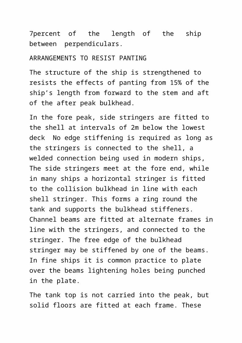
In the fore peak, side stringers are fitted to the shell at intervals of 2m below the lowest deck No edge stiffening is required as long as the stringers is connected to the shell, a welded connection being used in modern ships, The side stringers meet at the fore end, while in many ships a horizontal stringer is fitted to the collision bulkhead in line with each shell stringer. This forms a ring round the tank and supports the bulkhead stiffeners. Channel beams are fitted at alternate frames in line with the stringers, and connected to the stringer. The free edge of the bulkhead stringer may be stiffened by one of the beams. In fine ships it is common practice to plate over the beams lightening holes being punched in the plate.
The tank top is not carried into the peak, but solid floors are fitted at each frame. These floors are slightly thicker than those in the double bottom space and are flanged on their free edge.
The collision bulkhead is stiffened by vertical bulb plates spaced about 600 mm apart inside the peak. It is usual to fit horizontal plating because of the excessive taper on the plates which would occur with vertical plating..
The structure in the after peak is similar in principle to that in the fore peak, although the stringers and beams may be fitted 2.5m apart. The floors should extend above the stern tube or the frames above the tube must be stiffened by flanged tie plates to reduce the possibility of vibration.
ARRANGEMENTS TO RESIST POUNDING
The structure is strengthened to resist the effects of pounding from the collision bulkhead to 25% of the ship’s length from forward. The flat bottom shell plating adjacent to the keel on each side of the ship

is increased in thickness by between 15% and 30% depending upon the length of the ship, larger ships having smaller increases.
In addition to increasing the plating the unsupported panels of plating are reduced in size. In transversely framed ships the frame spacing is this region is 700 mm compared with 750 mm to 900 mm amidships. Longitudinal girders are fitted 2.2 m apart, extending vertically from the shell to the tank top, while intermediate half-height girders are fitted to the shell, reducing the unsupported width to 1.1 m. Solid floors are fitted at every frame space and are attached to the bottom shell by continuous welding.
If the bottom shell of a ship is longitudinally framed, the spacing of the longitudinal is reduced to 700 mm and they are continued as far forward as practicable to the collision bulkhead. The transverse floors may be fitted at alternate frames with this arrangement and the full-height side girders may be fitted 2.1 m apart. Half-height girders are not required

Q3. Describe the phenomenon of parametric rolling. what are the measures taken to prevent parametric rolling of ships. 2019/FEB
Answer:- Parametric rolling occurs when the natural frequency of the loaded ship is the same as the wave frequency and their amplitudes are in phase. It is a synchronous rolling condition when the roll angle amplitude becomes maximum and can be dangerous
Rolling and pitching is a part of every ship that is going out at the sea. The first thing you might think up on hearing the word “Parametric rolling” is that it must be a type of rolling movement occurring in ships. Rolling and Pitching is a normal movement phenomenon which occurs in all kind of ships, so what is new about this?
The difference is that “Parametric Rolling” is a type of movement that is experienced only on Container Ships.
Causes of Parametric Rolling
The size of container ships is increasing drastically as companies are looking forward to monster ships; for e.g. Maersk’s Triple-E Vessels. The new container ships coming to the market have large bow flare and wide beam to decrease the frictional resistance which is generated when the ship fore end passes through the water, making it streamlined with the hull.
As the wave crest travels along the hull, it results in flare immersion in the wave crest and the bow comes down. The stability (GM ) varies as a result of pitching and rolling of the ship. The combination of buoyancy and wave excitation forces push the ship to the other side.
Causes of Parametric Rolling
The size of container ships is increasing drastically as companies are looking forward to monster ships; for

e.g. Maersk’s Triple-E Vessels. The new container ships coming to the market have large bow flare and wide beam to decrease the frictional resistance which is generated when the ship fore end passes through the water, making it streamlined with the hull.
As the wave crest travels along the hull, it results in flare immersion in the wave crest and the bow comes down. The stability (GM ) varies as a result of pitching and rolling of the ship. The combination of buoyancy and wave excitation forces push the ship to the other side.
The similar action takes place as the bow goes down in the next wave cycle resulting in synchronous motion which leads to heavy rolling up to 30 degree in a few cycles. This type of rolling is known as Parametric rolling.
This phenomenon occurs only when the sea condition is in head / stern or anywhere near to them. There are two pitch cycles- maximum and minimum. The period of roll is half the natural rolling period which coincides with large phase angle and maximum roll always occurs when the ship is pitching down i.e. bow is down.
Effects of Parametric Roll

Heavy stresses in ship structure especially in fore and aft parts
Extreme stresses on container and their securing system resulting in failure of the same and even loss of containers
Unpleasant for the crew of the ship Variation in the load of ship’s propulsion engine If not tackled quickly, it can result in capsizing of ship
What to do in case of Parametric Rolling on ships?
Do not panic in such situation. Keep your calm
If rolling and pitching occurs simultaneously, avoid a head on sea and change the route.
Always maintain a correct GM. Ship should not be too tender or too stiff.
The roll damping measures must be quickly used
Q4. With the help of sketches explain the different types of strakes used in ship construction. What material is generally used for Hull plating and What are the tests carried out on Hull steel plating for certification as per class rules. 2019/FEB
Answer:- A strake is a sheet of platingwith standard dimensions of length and width. The thickness is indicated by the term scantling . The strakes when joined by welding becomes the hull body without the internal stiffeners and separation bilkheads The upper most strake on the hull is called the sheer strake since it is parallel to the sheer line of the deck. From thre sheer strake the scantlings gradually reduce in the down ward direction the rows of strakes are benoted alphabetically down wards till the turn of the bilge.

The bilge strake is special and itis the thinnest strake to take up any strain caused by hogging and sagging. From the turn of the bilge at the bottom the scantlings of the strakes are gradually increased till the keel strake which is the thickest strake on the ship. The two adjoining strakes on either side of the keel strake is called the garboard strake. They are slightly thinner than the keel strake.
Mild steel or low carbon steel in several grades has been used as a ship structure material for over a century. It has the advantages of having a relative good strength weight ratio whist the cost in not excessive.

There are four grades of steel in common use, specified by the classification societies as a grades A, B, D and E depending largely upon their degree of notch toughness. Grade A has the least resistance to brittle fracture whilst Grade E is termed “ extra notch tough” . Grade E has sufficient resistance to crack for it to be used extensively for main structural material.
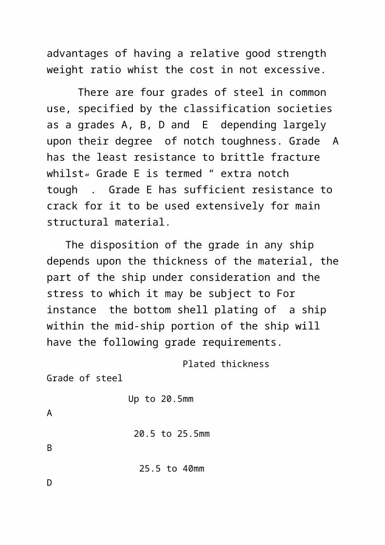
The disposition of the grade in any ship depends upon the thickness of the material, the part of the ship under consideration and the stress to which it may be subject to For instance the bottom shell plating of a ship within the mid-ship portion of the ship will have the following grade requirements.
Plated thickness Grade of steel
Up to 20.5mm A
20.5 to 25.5mm B
25.5 to 40mm D
Above 40mm E
The tensile strength of the different grade remains constant at between 400MN/m2 and 490MN/m2. The difference is in the chemical composition which improves the impact strength of D and E steels. Impact resistance is measured by means of charpy test in which specimens may be tested at a variety of temperatures. The following table shows the minimum values required by Lloyd’s Register.
TYPE OF STEEL TEMPREATURE IMPACT RESISTANCE B 0 0C 27 JOULESD 0 0C 47 JOULESE -400 C 27 JOULES

Higher tensile steels
As oil tanker and bulk carries increased in size thickness of steel requied for main longtitude strength members also increased. In an attempt to reduce the thickness of material and hence reduce the light displacement of the ship . classification societies accept the use of steels of higher tensile strength. These steels are designated AH, HB, DH and EH and may be used to replace the normal grades for any given structural members. Thus a bottom shell plate amidships may be 30mm in thickness of grades DH steels.
The tensile strenghth is increased to between 490MN/m2 and 620 MN//m2 , having the same percentage elongation as the low carbon steel. Thus it is possible to form a structure combining low carbon steel with the more expensive thinner higher tensile steel. Latter is used where most effective, i.e., for upper deck plating and longitudinals, and the bottom shell plating and longitudinals.
Care must be taken in the design to ensure that the hull has an accectable standard of stiffening, otherwise the deflection pf the ship may become excessive . welding must be carried out using low hydrogen electrodes, together wih a degree of preheating. Subsequent repair must be carried out using the same type of steel and electrodes, it is a considerable advantage if the ship carries spare electrodes , while a plan of the ship should be available showing the extent of the material together with its specification.
Ship construction consists of fabrication of steel plating which involves cold forming of the steel plates to some degree of curvature an welding . Hence the steel shoud be sufficiently ductile to bend and form in the cold condition.

To ascertain the ductility standard the percentage elongation obtained in a tensile testing machine on standard test pieces is a good indication of ductility quality. Together with this the cold bend test carried out on standard plate sections confirms the ductility quality required. For class B,D,and E steels the charpy impact test is to be carried out. Hence the tests required are UTS with percentage elongation, cold bend test and Charpy impact test.
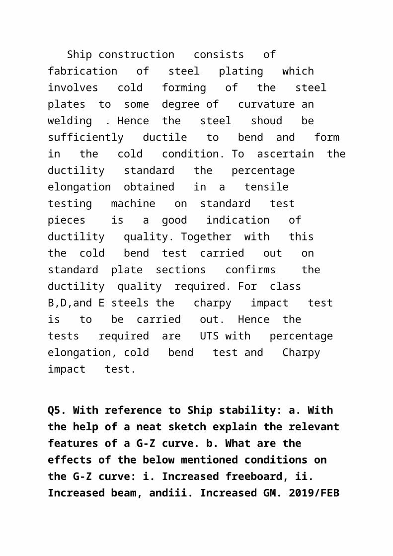
Q5. With reference to Ship stability: a. With the help of a neat sketch explain the relevant features of a G-Z curve. b. What are the effects of the below mentioned conditions on the G-Z curve: i. Increased freeboard, ii. Increased beam, andiii. Increased GM. 2019/FEB
Answer:-
The GZ curve is an exercise required to be carried out by the master / chief officer of the ship when the vessel has completed loading and the cargo properly secured. This curve gives an estimate of the range of statical stability or in other words the dynamic stability potential of the ship. The
most important information given by this curve is the range of heel the ship can take during the voyage when encountering bad weather. This curve is drawn for two conditions , one for departure condition with the fuel and fresh water in maximum planned condition , and a second curve with fuel and fresh water consumed during the voyage , which is called arrival condition. The arrival condition cuve is more critical than the departure condition because the initial metacentric height is reduced by G moving up and this condition is reduced GM for all angles of heel which results in a lower range.
(!) With increased freeboard the range of stability is increased because the anglr e of heel is extended till the deck edge comes in line with the water line see sketch given below.
(!!) With increased beam the second moment of the water plane area increases thereby initial GM is increased. The range of stability is therefore increased. .See sketch below.

(111) Increased GM(initial) is the same as condition (!!) . The relevant sketch will be same as for increased beam.
SECTION – II
Q6. What is Prismatic Co-efficient (CP). a. Derive the formula CP =Cb*Cm , where Cb = Co-efficient of fineness and Cm = midship section area co-efficient.

b. The length Of a ship is 18 times the draught. while the breadth is 2.1 times the draught. At the load water plane, the water plane area co-efficient is 0.83 and the difference between the T PC in sea water
and the T PC in fresh water is 0.7. Determine the length of the ship and the TPC in fresh water. 2019/FEB
Answer:- PRISMATIC COEFFICIENT CP is the ratio of the volume of displacement to the product of the length and the area of the immersed portion of the midship section.
Cp= vol of ∆ /length*area of immersed midship section
= / L X Am
But = Cb X L X B X d
And Am = Cm B X d
Substituting these in the expression for Cp ;
Cp =( Cb X L X B X d )/ ( L X Cm x B X d)
Cp = Cb / Cm or Cb= Cp * Cm
(b) Let d be the draught of the ship.
Hence the length of the ship is 18d and the beam of the ship is 2.1d. The water plane area of the ship is 18*2.1 *0.83*d2 = 31.374d2
31.374d2 *(1.025-1)*0.01 = difference in TPC between sea water and fresh water = 0.7 t
Solving this equation we have d= 9.447
Hence length of ship = 18 * 9.447 = 170 meters.
The TPC in fresh water = 31.374*9.447*9.447*0.01=28 T
Q7. With respect to Ship Propulsion: a. Explain the various efficiencies associated with propeller and shafting arrangement.
b. When a propeller of 4.8 m pitch turns at 1 10 rpm, the apparent slip is found to be —S % and the real slip is 1.5 S If the wake speed is 25 % of the ship speed, calculate the ship speed, apparent slip and the real slip. 2019/FEB.
Answer:- (a) The power produced by the engine is the indicated power ip. The mechanical efficiency of the engine is usually between about 80% and 90% and therefore only this percent of the ip is transmitted to the shaft, giving the shaft power sp or brake power bp.
sp or bp = ip X mechanical efficiency
shaft losses vary between about 3% and 5% and therefore the power delivered to the propeller, the delivered power dp, is almost 95% of the sp.
dp = sp X transmission efficiency
The delivered power may calculated from the torque on the shaft
dp = torque X2 π n
The propeller has an efficiency of 60% to 70% and hence the thrust power tp is given by :
tp = dp X propeller efficiency
The action of the propeller in accelerating the water created a suction on the after end of the ship. The thrust exerted by the propeller must exceed the total resistance by this amount. The relation between thrust and resistance may be expressed in the form.
Rt = T (1 - t )
Where t is the thrust decution factor.
The thrust power will therefore differ from the effective power. The ratio of ep to tp is known as the hull efficiency which is a little more than unity for single screw ships and about unity for twin screw ships.
ep = tp X hull efficiency
In an attempt to estimate the power required by the machinery from the calculation of ep, a quasi propulsive coefficient QPC is introduced. This is the relation of ep to dp and obviates the use of hull efficiency and propeller efficiency . The prefix quasi is used to show that the machinery and the transmission losses have not been taken into account.
ep = dp X QPC
(b) Let V be the ship speed. The apparent slip is -s a negative unknown percentage because slip is always given as a percentage of the speed.
The theoretical speed is given by (110*4.8*60)/1852= 17.1 knots
The real slip is 0.25 V and hence the real slip is given by
100*(17.1-0.75V)/17.1= 1.5S-----------------(1)
The apparent slip is given by

100*(17.1-V)/17.1= -S------------------------(2)
solving these two simultaneous equations by eliminating s we have
2.5*17.1-2.25V = 0
Hence V = 19 knots
Substituting for V in equation (1) we have 100*(17.1—14,25)/1.5*17.1) =s = 11.11
Hence the real slip is 11.11 *1.5 = 16.66 percent
The apparent slip is -s which is -11.11 percent
Q8. With the aid of sketches: a. Explain various lines plan.
b. The half -breadths of waterplane of a ship of 120m length ad 15m breadth are given below:
station 0 1 2 3 4 5 6 7 8Half breadth
1.6 2.8 5.5 6.4 7.3 6.2 4.2 2.0 0
Calculate i) Water plane area ii) TPC in salt water iii) Cw iv) LCF from Mid-ship 2019/FEB
Answer:- (b)
Half breadth
SM PRODUCTFor area
LEVER fromAft station
PRODUCTFor moment
1.6 1 1.6 0 0 2.8 4 11.2 1 11.2 5.5 2 11 2 22 6.4 4 25.6 3 76.8 7.3 2 14.6 4 58.4

6.2 4 24.8 5 99.2 4.2 2 8.4 6 50.4 2.0 4 8 7 56 0 1 0 8 0 TOTAL 105.2 TOTAL 374
Area of WP = 2*15/3*105.2 = IO52 m2
TPC in salt water = 1052*0.01*1.025=10.78 tons.
CW = 1052/(120*14.6) =0.6
LCF from aft station = 374/105.2*15= 53.32 m
HENCE FROM MIDSHIP = 60 – 53.32 =6.68 M AFT OF MID SHIOP
Answer:- (a) Description

The point of intersection of these planes with the hull results in a series of lines that are projected onto a single plane located on the front, top, or side of the ship. This results in three separate projections, or views, called the Body Plan, the Half-Breadth Plan, and the Sheer Plan.To visualize, place the ship in an imaginary rectangular box whose sides touch the keel and sides of the ship. The bottom, side and front of the box will serve as the basis for three orthogonal projection screens on which lines will be projected onto. The lines to be projected result from the intersection of the hull with planes that are parallel to each of the three orthogonal planes mentioned.Body Plan
Planes parallel to the front and back of the imaginary box are called stations. There are three important stations. The intersection of the stem of the ship at the design water line is called Forward Perpendicular (FP). The intersection of the stern at design waterline(immersed transom) or the rudder stock is called the Aft Perpendicular (AP). The station midway between the perpendiculars is called the midships stations.Each station plane will intersect the ship's hull and form a curved line at the points of intersection. These lines are called sectional linesand are all projected onto a single plane called the Body Plan.The body plan takes advantage of the ship's symmetry. Hence only half the section is show; the sections forward of amidships are drawn on the right side, and the sections aft of the

amidships are drawn on the left side. The amidships section is generally shown on both sides of the body plan. The vertical line in the center separating the left and right half of the ship is called the centerline.Half-Breadth Plan
The bottom of the box is a reference plane called the base plane. The base plane is usually level with the keel. A series of planes parallel and above the base plan are imagined at regular intervals, usually at every meter. Each plane will intersect the ship's hull and form a line at the points of intersection. These lines are called waterlines and are all projected onto a single plane called the Half-Breadth Plan.Each waterlines shows the true shape of the hull from the top view for some elevation above the base plane.The water lines referred to here has nothing to do with where the ship actually floats. There waterlines are the intersection of the ship's hull with some imaginary plane above the base plane.Since ships are symmetric about their centerline they only need be drawn for the starboard or port side, thus the name Half-Breadth Plan.
Sheer Plan A plane that runs from bow to stern directly through the center of the ship and parallel to the sides of the imaginary box is called the centerline plane. A series of planes parallel to one side of the centerline plane are imagined at regular intervals from the centerline. Each plane will intersect the ship's hull and form a curved line at the points of intersection. These lines are

called buttock or butt linesand are projected onto a single plane called the Sheer Plan.Each buttock line shows the true shape of the hull from the side view for some distance from the centerline of the ship. The centerline plane shows a special butt line called the profile of the ship.
Q9. With reference to inclining experiments; A. List the precautions necessary before an inclining experiment is carried out.
B. A box shaped vessel, 50 metres long × 10 metres wide, floats in salt water on an even keel at a draft of 4 metres. A centre line longitudinal watertight bulkhead extends from end to end and for the full depth of the vessel. A compartment amidships on the starboard side is 15 metres long and contains cargo with permeability 30%. Calculate the list if this compartment is bilged.

KG = 3 metres. 2017/SR11 2018/SR03 2018/SR09 2018/OCT 2019/JAN 2019/FEB
Answer:- Repeat Question. Refer toQ7 Nov 2017 NA
Q10. With reference to subdivisional stability; A. Describe briefly the significance of the factor of subdivision.
B. A ship of 8000 tonne displacement floats upright in seawater. KG = 7.6m and GM = 0.5m. A tank, KG is 0.6m above the keel and 3.5m from the centreline, contains 100 tonne of water ballast. Neglecting the free surface effect, calculate the angle which the ship will heel, when the ballast water is pumped out. 2018/OCT 2019/JAN 2019/FEB
Answer:- Repeat question.