
sayyidhussain.weebly.com · Web viewThe signal going in the H-Bridge goes through a mosfet driver...
69
Figure 1 H Bridge Description Below are some important specifications of the H-Bridge Input Voltage = 4.7V to 43 V Input Signal Voltage = 4.5 to 7V Maximum Current = 3 Amps Current turn off Delay = 1.5us (Max) Below is the table will explain what signal to give to the pin to move the motor Motor Status C (Pin10) D (Pin 12) Forward 1 0 Reverse 0 1 Brake 1 1 Table 1 H-Bridge Control Signal Note: Bring a motor in sudden brake both the terminals of the motor should be either high or low 1
Transcript of sayyidhussain.weebly.com · Web viewThe signal going in the H-Bridge goes through a mosfet driver...

Figure 1 H Bridge Description
Below are some important specifications of the H-Bridge
Input Voltage = 4.7V to 43 V Input Signal Voltage = 4.5 to 7V Maximum Current = 3 Amps Current turn off Delay = 1.5us (Max)
Below is the table will explain what signal to give to the pin to move the motor
Motor Status C (Pin10) D (Pin 12)Forward 1 0Reverse 0 1
Brake 1 1Table 1 H-Bridge Control Signal
Note: Bring a motor in sudden brake both the terminals of the motor should be either high or low
1

Altium Circuit
Figure 2 H-Bridge Circuit
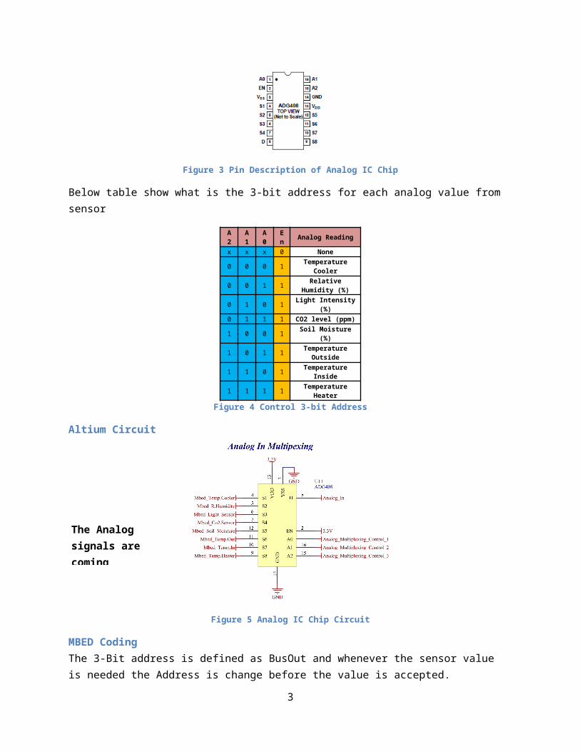
Analog MultiplexingMbed has 6 pins dedicated to read analog values. However, there are 8 Analog Sensor. Hence an analog multiplexer (ADG408) was decided to use. The ADG408 switches one of eight inputs to a common output as determined by the 3-bit binary address lines A0, A1 and A2. The ADG408 are designed to provide low power dissipation yet gives high switching speed and low on resistance. All channels exhibit break before make switching action, preventing momentary shorting when switching channels.the IC Chip also has Low R(ON).
Some important specification of the IC Chip
Input High Voltage = 2.4V (Min) Input Low Voltage = 0.8V Time to switch = 10ns Supply Voltage = 0 to 25V
Below is the pin description of the IC Chip:
Figure 3 Pin Description of Analog IC Chip
2
The signal going in the H-Bridge goes through a mosfet driver because of two main reasons:
To give signal of 5V from 3.3V To protect the MBED pins
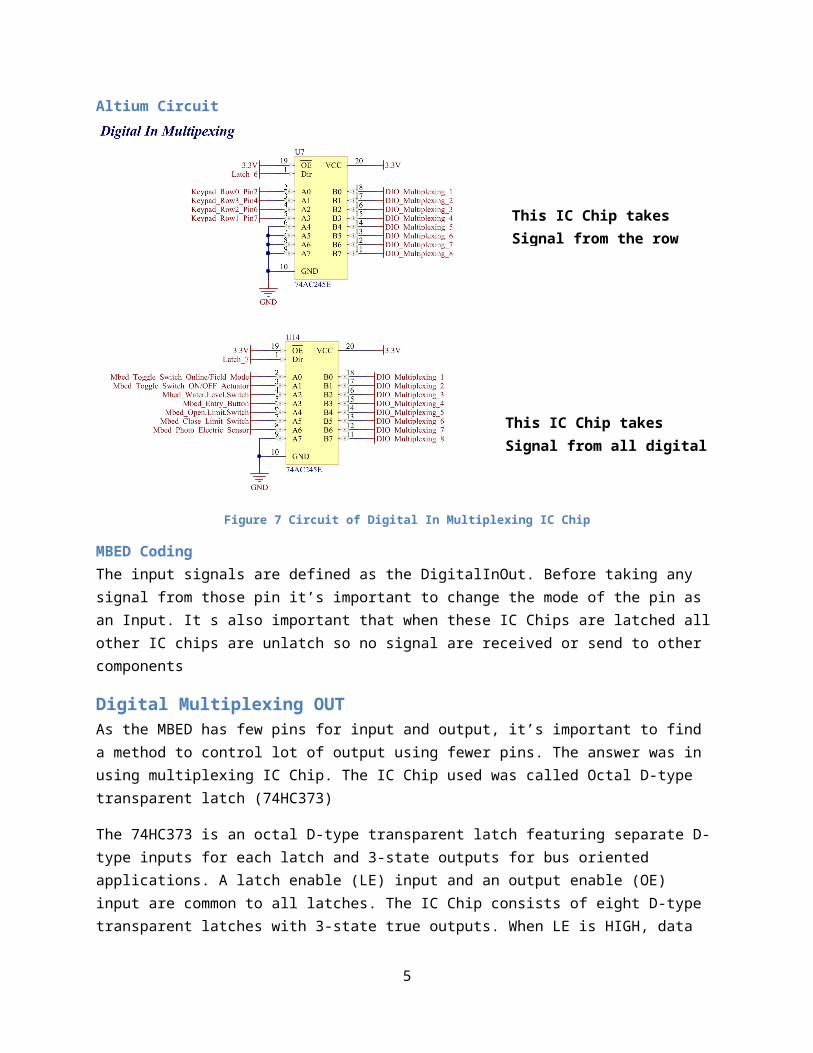
Below table show what is the 3-bit address for each analog value from sensor
A2 A1 A0 En Analog Reading
x x x 0 None0 0 0 1 Temperature Cooler0 0 1 1 Relative Humidity (%)0 1 0 1 Light Intensity (%)0 1 1 1 CO2 level (ppm)1 0 0 1 Soil Moisture (%)1 0 1 1 Temperature Outside1 1 0 1 Temperature Inside1 1 1 1 Temperature Heater
Figure 4 Control 3-bit Address
Altium Circuit
Figure 5 Analog IC Chip Circuit
MBED CodingThe 3-Bit address is defined as BusOut and whenever the sensor value is needed the Address is change before the value is accepted.
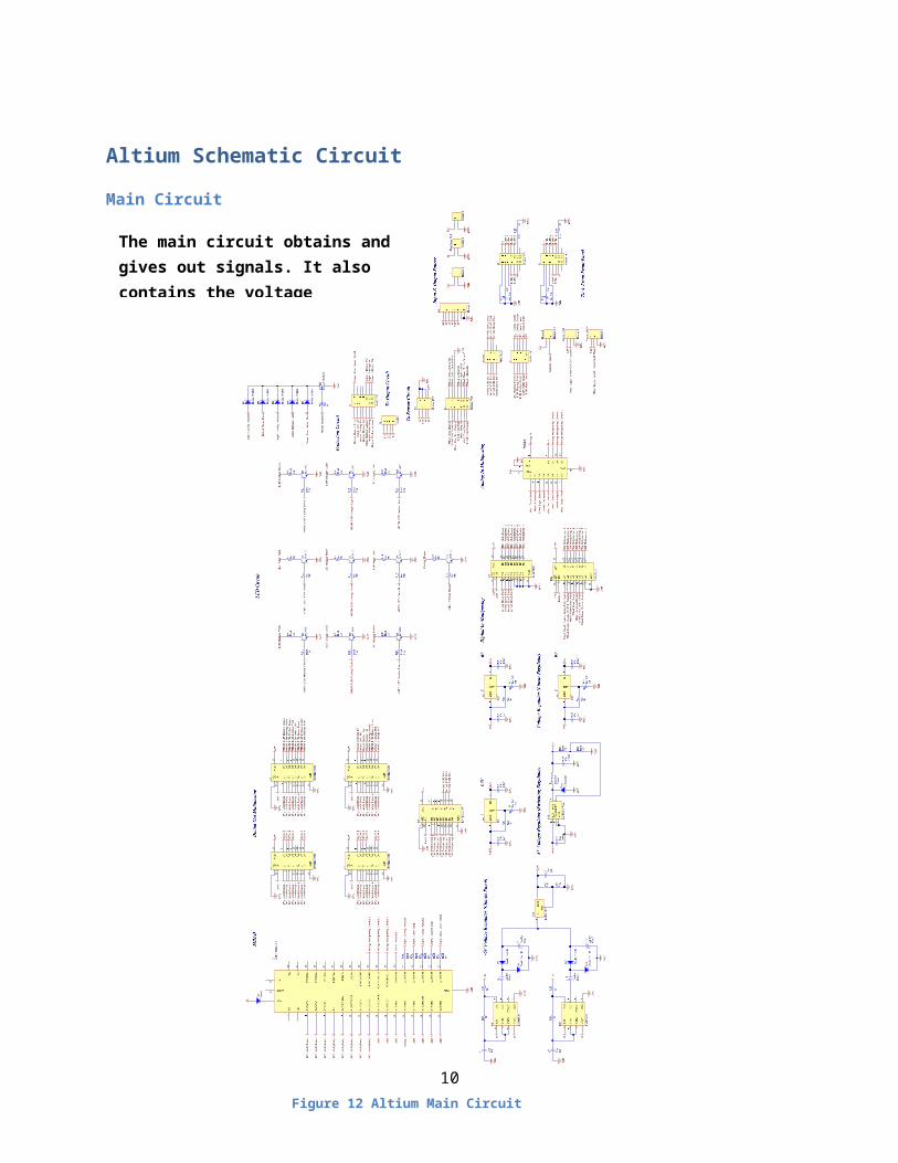
Digital Multiplexing INTo limit the amount of pin usage a Digital multiplexing IC Chip is used. The IC Chip is called Octal-Bus Transceiver (CD5474AC245). They are non-inverting three-state bidirectional transceiver-buffers intended for two-way transmission from “A” bus to “B” bus or “B” bus to “A”. The logic level present on the direction input (DIR) determines the data direction. When the output enable input (OE) is HIGH, the outputs are in the high-impedance state.
Below is pin map of the IC chip
3
The Analog signals are coming directly from sensor

Figure 6 Digital In IC Chip Description
Below are some important specifications about the IC Chip
Supply Voltage = -0.5 to 6 V DC Output Current = ± 50 mA Typical Propagation Delay = 4ns Buffered Inputs
Below table will give an explanation about what signal to give the IC chip for different conditions:
OE (Inverse) DIR ConditionLow High A BLow Low B AHigh Doesn’t matter Isolation
Table 2 Controlling Pin of Digital In Multiplexing IC Chip
4
Altium Circuit
Figure 7 Circuit of Digital In Multiplexing IC Chip
MBED CodingThe input signals are defined as the DigitalInOut. Before taking any signal from those pin it’s important to change the mode of the pin as an Input. It s also important that when these IC Chips are latched all other IC chips are unlatch so no signal are received or send to other components
Digital Multiplexing OUTAs the MBED has few pins for input and output, it’s important to find a method to control lot of output using fewer pins. The answer was in using multiplexing IC Chip. The IC Chip used was called Octal D-type transparent latch (74HC373)
The 74HC373 is an octal D-type transparent latch featuring separate D-type inputs for each latch and 3-state outputs for bus oriented applications. A latch enable (LE) input and an output enable (OE) input are common to all latches. The IC Chip consists of eight D-type transparent latches with 3-state true outputs. When LE is HIGH, data at the Dn inputs enters the latches. In this condition the latches are transparent, i.e. a latch output will change state each time its corresponding D input changes. When LE is LOW the latches store the information that was present at the D inputs a set-up time preceding the HIGH-to-LOW transition of LE. When OE is LOW, the contents of the 8 latches are available at the outputs. When OE is HIGH, the outputs go to the high impedance OFF-state. Operation of the OE input does not affect the state of the latches.
Below is the pin map of the IC Chip
5
This IC Chip takes Signal from the row pins of the Keypad
This IC Chip takes Signal from all digital sensors and switches

Figure 8 Digital Out Multiplexing IC Chip
These 8-bit latches feature 3-state outputs designed specifically for driving highly capacitive or relatively low-impedance loads. They are particularly suitable for implementing buffer registers, I/O ports, bidirectional bus drivers, and working registers.
Below is the table which explain the using of the IC Chip
Input OutputOE (Inverse) LE D Q
Low High High HighLow High Low LowLow Low Doesn’t Matter Previous valueHigh Doesn’t Matter Doesn’t Matter Impedance
Table 3 Controlling condition of Digital Out Multiplexing
Some important Specification about the IC Chip:
Supply Voltage = -0.5 to 7 V Supply Current = 70mA (Maximum)
Input clamp current = ± 20mA Output clamp current = ± 20mA
CalculationAs 5 Multiplexing IC Chip were used it had to make sure that the amount of current taken by all IC Chip could be supplied by the MBED
As per the datasheet the supply current of each pin is 100mAmps
The Digital In Multiplexing Leakage current is 10µAmps
The Digital Out Multiplexing Leakage current is 10µAmps
The total current is:
Digital In Multiplexing x 5 = 10µAmps * 5 = 50 µAmps
Digital Out Multiplexing x 2 = 10µAmps * 2 = 20 µAmps
Total current = 50 µAmps + 20 µAmps = 70 µAmps
6

Altium Circuit
Figure 9 5 Digital Multiplexing Out IC Chip
MBED CodingThe Output signals are defined as the DigitalInOut. Before giving any signal from those pin it’s important to change the mode of the pin as an Output. It’s also important that when these IC Chips are latched all other IC chips are unlatch so no signal are received or send to other components.
CommunicationDifferent parameters of the whole project are send to a device used by the ITs called raspberry pie. The data is sending in the form of serial using serial pot of the mbed. The MBED is capable to send serial data through 4 ports where 3 are through pin and one through the mini USB. The minim USB port is used to send the data which is connected to a cable and the other end of the cable is connected to raspberry pie. As a lot of data has to be send, a specific format was made:
Start Packag
e
Address Packag
e
Data Packag
e
End Packag
eS xx xx E
Start Package
7
These two IC Chip will be connected to the LCDs
These two IC Chip will be connected all LEDs and other Actuators
This IC Chip is to take signals from the Column pin of the keypad
Figure 10 Raspberry Pie

The programs will not accept any data till it doesn’t receive ‘S’. The benefit of start Package is that the programme knows when the message and address data is send and receive will be able to synchronize with the transmitter
Address Package
As lot of data will be send the receiver has to know what data us for which parameter, hence the before sending the data the a letter will be send to tell the receiver the coming data is for what.
Data Package
The data package will actually send the data which will either be 1s or 0s or certain values.
End Package
End Package is a very important part in transmitting data. Till it doesn’t receive the end package it will not accept any data. Till it doesn’t receive a ‘E’ it will keep accepting the data and adding up their values.
Below is the table for the data to be send:
Description Address Data Message Data Range of numberCooling Actuator Temperature Sensor a 0 to 75 0 to 75Heating Actuator Temperature Sensor b 0 to 75 0 to 75
Inside Temperature Sensor c 0 to 75 0 to 75Outside Temperature Sensor d 0 to 75 0 to 75
Soil Moisture Sensor e 0 to 100 (Not Sure) 0 to 100 (Not Sure)Light Sensor f 0 to 100 (Not Sure) 0 to 100 (Not Sure)CO2 Sensor g 0 to 20,000 0 to 20,000
Relative Humidity Sensor h 0 to 100 0 to 100Temperature Set point i 25-35 25-35Soil Moisture Set point j 0 to 100 (Not Sure) 0 to 100 (Not Sure)Light Intensity Set point k 0 to 100 (Not Sure) 0 to 100 (Not Sure)
Heating Process l 1/0 1/0Heating Vent Status m 0 to 100 0 to 100
Heater Status n 0 to 100 0 to 100Cooling Process o 1/0 1/0
Cooling Vents Status p 0 to 100 0 to 100Cooler Status q 0 to 100 0 to 100
Water Pump Status r 0 to 100 0 to 100CO2 Fan s 1/0 1/0
Halogen Light Status t 0 to 100 0 to 100Door Open u 1/0 1/0
Actuator Activation v 1/0 1/0Warning w 1/0 1/0
Water Level x 1/0 1/0Figure 11 Transmitting Data Description
MBED CodingThe data will be send in every 10 seconds with the help of ticker. The ticker will call a function in every 1 second and the data will be send through USB port.
8

Altium Schematic Circuit
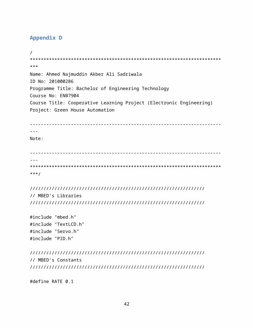
Main Circuit
9
The main circuit obtains and gives out signals. It also contains the voltage regulators and the MBED
Figure 12 Altium Main Circuit
Sensor Circuit
10
The Sensor Circuit contains all the circuit related to sensors and all the sensor are connected to this PCB. The sensors also get their power supply from this PCB. The sensors reading are obtain by this circuit and given to the main circuit via rainbow wires
Figure 13 Altium Sensor Circuit

Output Circuit
11
The Output circuit carries high current. All the actuators are connected to the circuit with help of MOSFET. This circuit also has the H-Bridge that control the DC Motor the Door
Figure 14 Altium Output Circuit

12

PCB (Printed Circuit Board)The minimum track size used is 1.4 mm and clearance 0.7mm. The reason for this specification is that it’s easy for the PCB machine as well as its easy for manufacturer to solder the components
Main Circuit
13

Figure 15 Main Circuit PCB
Sensor Circuit
14

Output CircuitThe output circuit will have all the actuators which will take high amount of current. Therefore the PCB tracks sizes have to vary so that it can carry high current
Track Size in the PCB
Specification of the PCB
-External Track
-1oz/ft2 thickness of track
-Temperature - 30’C
Motor (Output Circuit)
Voltage = 5 V Peak current = 2 amps
From the graph in Appendix A
Minimum Clearance = 0.2 mm
From the graph in Appendix B
Minimum Track Size =0.02 inches = 0.508 mm (approx)
Sensors (Sensor Circuit)
Voltage = 6 V Maximum Current = 0.2 amps (By CO2 Sensor)
From the graph in Appendix A
Minimum Clearance = 0.2 mm
15
Figure 16 PCB Sensor Circuit

From the graph in Appendix B
Minimum Track Size =0.001 inches = 0.0254 mm (approx)
Cooling Peltiers (Output Circuit)
Voltage = 24 V Maximum current = 5.5 amps
From the graph in Appendix A
Minimum Clearance = 0.2 mm
From the graph in Appendix B
Minimum Track Size =0.05 inches = 1.3 mm (approx)
Heating panels (Output Circuit)
Voltage = 24 V Maximum current = 9.5 amps
From the graph in Appendix A
Minimum Clearance = 0.2 mm
From the graph in Appendix B
Minimum Track Size = 0.150 inches = 3.81 mm (approx)
Mosfet Driver (Output Circuit)
Voltage = 12V Peak current = 1.5 amps
From the graph in Appendix A
Minimum Clearance =0.2 mm
From the graph in Appendix B
Minimum Track Size = 0.0100inches = 0.25mm (approx)
Ground (Output Circuit)
Voltage = 24V Peak current = 40 amps (Worst case Scenario, this is the limit of the bench power supply)
From the graph in Appendix A
16

Minimum Clearance =0.2 mm
From the graph in Appendix B
Minimum Track Size = 0.400+ inches = 10mm (approx)
Figure 17 PCB Output Circuit
17

Control System(Control system, 2015)
A control system is a device, or set of devices, that manages, commands, directs or regulates the behavior of other devices or systems. Industrial control systems are used in industrial production for controlling equipment or a machine.
There are two common classes of control systems, open loop control systems and closed loop control systems. In open loop control systems output is generated based on inputs. In closed loop control systems current output is taken into consideration and corrections are made based on feedback. A closed loop system is also called a feedback control system.
In this project, a close loop controller is used. PID controller is used as it is easy to use and MBED Community has a library pre made which make the programmer easy to use it
PIDA proportional-integral-derivative controller (PID controller) is a generic loop feedback mechanism. It measures a process variable (e.g. temperature), and checks it against a desired set point (e.g. 100 degrees celsius); it then attempts to adjust the process variable by changing a controller output (e.g. PWM signal to an electric heater) which will bring the process variable closer to the desired set point.
Figure 18 PID Close Loop
MBED Different technique used in making codes for MBED:
DigitalInOut
18

The DigitalInOut interface is used as a bi-directional digital pin, used to read the value of a digital pin when set as an input, or write the value when set as an output. Any of the numbered mbed pins can be used as a DigitalInOut.
BusIn
The BusIn interface is used to create a number of DigitalIn pins that can be read as one value. Any of the numbered mbed pins can be used as a DigitalIn in the BusIn.
BusOut
The BusOut interface is used to create a number of DigitalOut pins that can be written as one value.
Ticker
The Ticker interface is used to setup a recurring interrupt to repeatedly call a function at a specified rate. Any number of Ticker objects can be created, allowing multiple outstanding interrupts at the same time. The function can be a static function, or a member function of a particular object.
Timer
The Timer interface is used to create, start, stop and read a timer for measuring small times (between microseconds and seconds). Any number of Timer objects can be created, and can be started and stopped independently
Serial
Serial is a generic protocol used by computers and electronic modules to send and receive control information and data. The Serial link has two unidirection channels, one for sending and one for receiving. The link is asynchronous, and so both ends of the serial link must be configured to use the same settings.
Servo
This library controls a standard R/C model servo using a PwmOut signal, and provides control of the servo between min and max by setting it to 0.0 - 1.0.
As all servos respond differently, you can also use the calibrate function the range, so 0.0 - 1.0 is the maximum range of the servo. The underlying PwmOut period is set to 20ms, and by varying the pulsewidth (up to a maximum of 0.5ms to 2.5ms) the position of the servo is changed, usually by around 180 degrees. The library lets you calibrate the exact range.
LCD Screen
Controlling text LCD panels, which use the HD44780 LCD display driver.
19

CodeCode to enter data & Display/Monitor different parameters
Refer Appendix D
Codes for transmitting
Refer Appendix C
Latching Codes
Refer Appendix E
LabviewLabview program is used to tune the PID value. LabVIEW is a graphical programming platform that helps engineers scale from design to test and from small to large systems. LabVIEW software is ideal for any measurement or control system, and the heart of the NI design platform. Integrating all the tools that engineers and scientists need to build a wide range of applications in dramatically less time.
Front Panel
Figure 19 Front Panel of Labview
20
Pointer bar for user to put set point
Bar to show process value
Graph to show real time process value and set point
Graph to show real time process value and set point
User can select which serial port
Percentage of duty cycle

Block Diagram
Figure 20 Block Diagram of Labview
Recommendation Below are some recommendations which would help to improve the project
Better Cooling and Heating actuator
Having better heating & cooling actuator because the heat sink in the actuator stores the heat energy and keeps giving out the energy after the actuator is closed. Using a radiator would be preferable as it would response linearly.
Better Light Sensor
The Light sensor used currently is much more sensitive to infrared than visible light, therefore a better photodiode could be used which is much more sensitive to visible light
Better Soil Sensor
The soil sensor used currently has a short life and need calibration very often. Plus this get corrode soon depending on the acidity of the soil.
Better Controller
The PID controller made in this project using trial and error method. If the transfer function of the house could be derived then many complex controllers could be used or better values of PIC controller could be derived
21
To receive from MBED
To send from MBED
SubVI for PID

Better Power Source
The power supply is a bench power supply but it would b a good idea if the power comes from a green
source.
Better Microcontroller
The microcontroller used is a MBED. MBED is generally used from academic purpose. A different microprocessor could be used like ATMEL with lot of pins which make the controlling of all the function easily
Bill of Material (BOM)
Sensor CircuitDescription Designator PartNumber Quantity Value
High Conductance Fast Diode D10 1Header, 22-Pin Input & Output1 1
Header, 4-Pin, Dual row P23 1Header, 7-Pin, Dual row P24 1
Potentiometer R57, R65 2 1KResistor R58, R59, R62, R63, R64, R68, R69,
R70, R71, R72, R73 11 1K, 470K, 1K, 1K, 1K, 1K, 1K, 4.5K, 1K, 6.5K, 0.74K
Potentiometer R60, R61, R66, R67 4 5KLow Power Dual Operational
Amplifier U23, U24 LM358AN 2
Table 4 BOM of Sensor Circuit
Output CircuitDescription Designator PartNumber Quantity Value
Header, 2-Pin 1, 5, Door_Motor1, P7 4 Capacitor C9 1 100uFCapacitor C10 1 470uF
Capacitor C11, C12, C13, C101 4100pF, 100pF, 100pF, 100nF
Computer Diode D4, D5, D6, D7 4 High Conductance Fast Diode D8, D9 2 Schottky Diode D11 1 Inductor L2 1 220uFHeader, 6-Pin P2 1 Header, 7-Pin, Dual row P3 1 Header, 8-Pin P4 1 Header, 4-Pin P5, P8 2
Q1, Q2, Q3, Q4, Q5, Q6, Q7, Q8, Q9, Q10, Q11, Q12, Q13, Q14, Q15, Q16, Q17, Q18, Q19 19
Resistor
R1, R2, R3, R5, R6, R7, R11, R12, R14, R15, R19, R21, R22, R25, R26, R28, R29, R30, R33 19 1K
Resistor R35, R36, R46 3 3K, 1K, 100Tapped Resistor R49 1 1K1.5A Dual High-Speed Power MOSFET Driver, Non-Inverting, Industrial Temperature
U1, U2, U3, U4, U5, U6, U7, U8, U9, U10, U11, U12, U13 13
Easy Switcher 3.0A Step-Down Voltage Regulator U15 1 Dual Full Bridge Driver U17 1 Timer U20 LM555CN 1
Table 5 BOM of Output Circuit
Main CircuitDescription Designator PartType Quantity Value
Header, 2-Pin 1, 8, Raspberry Pie1 Header 2 3 Header, 2-Pin Buzzer1 Header 2_1 1
Capacitor C1, C2, C3, C4, C5, C8, C9, C13, C14 Cap 91nF, 1uF, 0.1uF, 1uF, 0.1uF, 1uF, 1nF, 1uF, 0.1uF
Polarized Capacitor (Radial) C6, C7, C12, C15 Cap Pol1 4 470uFCapacitor C10 Cap 1 100uFCapacitor C11 Cap 1 470uF
22

High Conductance Fast Diode D1, D3, D3, D4, D5, D6 Diode 1N4148 6 Default Diode D2 Diode 1 High Conductance Fast Diode D7, D8, D10, D11 Diode 1N4148 4 Schottky Diode D9 D Schottky 1 Header, 4-Pin, Dual row Keypad1 MHDR2X4 1 Inductor L1 Inductor 1 220uFHeader, 7-Pin, Dual row P1, P5, P6, P8 Header 7X2 4 Header, 4-Pin P2 Header 4 1 Header, 4-Pin, Dual row P3 Header 4X2 1 Header, 8-Pin P4 Header 8 1 Header, 5-Pin, Dual row P7 Header 5X2 1 Amplifier Transistor NPN Silicon Q1, Q2, Q3, Q5, Q6, Q7, Q8, Q9, Q10, Q11 BC547C 10 N-Channel Enhancement Mode Vertical DMOS FET Q4 ZVNL110A 1
Resistor
R1, R2, R3, R4, R5, R6, R7, R8, R9, R10, R11, R12, R13, R14, R15, R16, R17, R18, R19, R20, R21, R22, R24, R25, R29, R30, R40, R41, R42, R44 Res1 30
3K, 3K, 3K, 25K, 25K, 25K, 3K, 3K, 3K, 25K, 25K, 25K, 3K, 3K, 3K, 25K, 25K, 25K, 50, 50, 50, 50, 50, 25K, 240, 240, 3.3K, 240, 1K, 50
Resistor R26, R36, R39 10k 3 1KResistor R27, R37 2k 2 1KVariable Resistor R28, R31, R32, R34, R43 Res Adj1 5 920, 1.46K, 386, 920, 895Resistor R33, R38 Res1 2 350Resistor R35 120 1 1KHeader, 3-Pin Toggle_Mode1, Toggle_ON1 Header 3 2 Octal Transparent D-Type Latches with 3-State Outputs U1, U2, U4, U5, U6 SN74HC373N 5 U3 MBED MODULE 1 Octal Bidirectional Transceiver with 3-State Input/Output U7, U14 74AC245E 2 Timer U8, U15 LM555CN 2 Regulator Adjustable U9, U10, U16 LM317 3 U11 ADG408 1 3-Terminal Adjustable Negative Voltage Regulator U12 LM337BT 1 Easy Switcher 3.0A Step-Down Voltage Regulator U13 LM2576T-ADJ 1
Table 6 BOM of Main Circuit
Bahrain Perspective(PID controller, 2014)
A greenhouse is a building or complex in which plants are grown. Greenhouses allow for greater control over the growing environment of plants. Depending upon the technical specification of a greenhouse, key variable which may be controlled include temperature, levels of light and shade, irrigation, fertilizer application, and humidity. Greenhouses are often used for growing flowers, vegetables, fruits, and plants. Special greenhouse varieties of certain crops, such as tomatoes, are generally used for commercial production.
Advantages of Green house
Higher and more consistent yields per acre Limited exposure to damaging pests Natural sunlight and ventilation Longer growing seasons
23
Figure 21 Green House in Desert

A green house farming concept will be very useful in Bahrain. Bahrain consists of a low desert plain. It has mild winters and very hot, humid summers. 92% of Bahrain is desert with periodic droughts and dust storms. These conditions are not suitable for farming. The geographical and climate condition make it difficult for farming.
Below is Bahrain Climate pattern yearly in form of graphs
Figure 22 Bahrain Weather pattern
As it can be seen Bahrain climate is extreme during summer and winter. Bahrain’s farmers avoid months like June, July, August and September. In addition due to change in humidity the soil looses moisture quickly. Bahrain climate can only support few farming crop which grow quickly and can withstand Bahrain’s harsh Climate. Hence, the Green House is a good Solution for Bahrain Agriculture. A variety of plants could be grown as we can control the climatic condition in the green House. Due to this, most plants could be grown at anytime of the year. This will increase the production of agricultural product (tomatoes, cabbages, carrots and etc) not at specific month but all the months of the year.
As Bahrain has to import majority of its vegetable and fruit from foreign country and statistic shows that it increase every decade by 4 %.As the fruit come from foreign countries it is coated with wax and chemical to keep it fresh, hence it would be better to increase the production of vegetable and fruits in Bahrain.
24

Bibliography555 Negative Voltage Power Supply Circuit. (n.d.). Retrieved from http://www.electronicecircuits.com/: http://www.electronicecircuits.com/electronic-circuits/555-negative-voltage-power-supply-circuit
Alphanumeric LCD Displays. (n.d.).
Buzzer. (2014, September 24). Retrieved from ww.wikipedia.com: http://en.wikipedia.org/wiki/Buzzer
Control system. (2015, Jan 3). Retrieved from www.wikipedia.com: http://en.wikipedia.org/wiki/Control_system
H bridge. (2015, January 2). Retrieved from www.wikipedia.com: http://en.wikipedia.org/wiki/H_bridge
Hitachi HD44780 LCD controller. (2014, July 2014). Retrieved from www.wikipedia.com: http://en.wikipedia.org/wiki/Hitachi_HD44780_LCD_controller
How Servo Motors Work. (n.d.). Retrieved from http://www.jameco.com/: http://www.jameco.com/jameco/workshop/howitworks/how-servo-motors-work.html
Limit switch. (2014, December 2014). Retrieved from www.wikipedia.com: http://en.wikipedia.org/wiki/Limit_switch
Measure Light Intensity using Photodiode. (n.d.). Retrieved from http://www.emant.com/: http://www.emant.com/324003.page
MG-811 CO2 Sensor Module. (n.d.). Retrieved from http://sandboxelectronics.com/: http://sandboxelectronics.com/?p=147
PID controller. (2014, Decmeber 12). Retrieved from www.wikipidia.com: http://en.wikipedia.org/wiki/PID_controller
Servo Mechanism. (n.d.). Retrieved from http://electrical4u.com/: http://electrical4u.com/servo-motor-servo-mechanism-theory-and-working-principle/
Servomotor. (2015, January 2015). Retrieved from www.wikipedia.com: http://en.wikipedia.org/wiki/Servomotor
SMPS Basics. (2005). Retrieved from http://www.ecircuitcenter.com/: http://www.ecircuitcenter.com/Circuits/smps_buck/smps_buck.htm
Switched-mode power supply. (2014, November 29). Retrieved from www.wikipedia.com: http://en.wikipedia.org/wiki/Switched-mode_power_supply
Thermoelectric cooling. (2015, January 4). Retrieved from www.wikipedia.com: http://en.wikipedia.org/wiki/Thermoelectric_cooling
25

(2011). Understanding Thermal Dissipation and Design of a. Dallas: TEXAS INSTRUMENT.
Wikipedia. (2014, 09 2). Retrieved from Greenhouse: http://en.wikipedia.org/wiki/Greenhouse
Images of the project
Figure 23 PCB of Project
26

Figure 24 Project Image 1
Figure 25 Project Image 2
27

Figure 26 Project Image 2
Figure 27 Project image 3
28

Figure 28 Project Image 4
Figure 29 Project Image 5
29

Figure 30 Project Image 6
FabricationBelow is a diagram showing important part of the project:
30
Air DuctAir Duct
Green House
Heating Actuator
Cooling Actuator
FanWater Tank
Front Panel
Louvers
PCB

Appendix
Appendix A
31

Appendix B
32

Appendix C#include "mbed.h"
Serial Raspberry(USBTX, USBRX);Ticker Transmitting;
///////////////////////////////////////////////////////////////////////////////////////////////int CATS=1,HATS=2,ITS=3,OTS=4,SMS=5,LS=6,CO2S=7,RHS=8,TS=9,MS=10,LIS=11,HP=12,HVS=13,HS=14,CP=15,CVS=16,CS=17,WPS=18,CO2F=19,HLS=20,DO=21,AA=22,W=23,WL=24;
int data = 0;char datadiscription = 'z';
char td;int dv;
/*THE BELOW TERMS WILL BE USE FOR COMMUNICATION
CATS = Cooling Actuator Temperature SensorHATS = Heating Actuator Temperature SensorITS = Inside Temperature SensorOTS = Outside Temperature SensorSMS = Soil Moisture SensorLS = Light SensorCO2S = CO2 SensorRHS = Relative Humidity SensorTS = Temperature SetpointMS = Soil Moisture SetpointLIS = Light Intensity SetpointHP = Heating ProcessHVS = Heating Vent StatusHS = Heater StatusCP = Cooling Process CVS = Cooling Vents StatusCS = Cooler StatusWPS = Water Pump StatusCO2F = CO2 FanHLS = Halogen Light StatusDO = Door OpenAA = Actuator ActivationW = WarningWL = Water Level
*/
33

///////////////////////////////////////////////////////////////////////////////////////////////// Function Declarationvoid SendingData(char td,int dv);
///////////////////////////////////////////////////////////////////////////////////////////////// Tikker Declarationvoid flip() { SendingData('a',CATS); SendingData('b',HATS); SendingData('c',ITS); SendingData('d',OTS); SendingData('e',SMS); SendingData('f',LS); SendingData('g',CO2S); SendingData('h',RHS); SendingData('i',TS); SendingData('j',MS); SendingData('k',LIS); SendingData('l',HP); SendingData('m',HVS); SendingData('n',HS); SendingData('o',CP); SendingData('p',CVS); SendingData('q',CS); SendingData('r',WPS); SendingData('s',CO2F); SendingData('t',HLS); SendingData('u',DO); SendingData('v',AA); SendingData('w',W); SendingData('x',WL);}///////////////////////////////////////////////////////////////////////////////////////////////
int main() { Transmitting.attach(&flip, 1); while(1) { wait(3);
}}
///////////////////////////////////////////////////////////////////////////////////////////////
34

// Function - Data Transmition ////void SendingData(char td,int dv){ // Start Package ////////////////// if(Raspberry.writeable()) { Raspberry.printf("S"); } wait(0.008);// Destination Package ////////////
if(Raspberry.writeable()) { Raspberry.printf("%c",td); } wait(0.008);// Data Package //////////////////
if(Raspberry.writeable()) { Raspberry.printf("%d",dv); } wait(0.008);//End Package ///////////////////
if(Raspberry.writeable()) { Raspberry.printf("E"); } wait(0.008);///////////////////////////////////Raspberry.printf("--");}/////////////////////////////////////////////////////////////////////
35

Appendix D
/*************************************************************************Name: Ahmed Najmuddin Akber Ali SadriwalaID No: 201000286 Programme Title: Bachelor of Engineering TechnologyCourse No: ENB7904Course Title: Cooperative Learning Project (Electronic Engineering)Project: Green House Automation
-------------------------------------------------------------------------Note:
-------------------------------------------------------------------------*************************************************************************/
////////////////////////////////////////////////////////////////// MBED's Libraries////////////////////////////////////////////////////////////////
#include "mbed.h"#include "TextLCD.h"#include "Servo.h"#include "PID.h"
////////////////////////////////////////////////////////////////// MBED's Constants////////////////////////////////////////////////////////////////
#define RATE 0.1
////////////////////////////////////////////////////////////////// MBED's LED (**Just for Indication**)////////////////////////////////////////////////////////////////
DigitalOut leda (LED1);DigitalOut ledb (LED2);DigitalOut ledc (LED3);DigitalOut ledd (LED4);
////////////////////////////////////////////////////////////////
36

// LCDa & LCDb////////////////////////////////////////////////////////////////
TextLCD lcda(p5,p6,p7,p8,p9,p10, TextLCD::LCD20x4);TextLCD lcdb(p5,p6,p7,p8,p9,p10, TextLCD::LCD20x4);
////////////////////////////////////////////////////////////////// Keypad////////////////////////////////////////////////////////////////
BusOut KeypadCols ( p20,p19, p18 ); BusInOut KeypadRows ( p17, p16, p15, p30 );
////////////////////////////////////////////////////////////////// DigitalIn/Out////////////////////////////////////////////////////////////////
DigitalInOut DIOa(p5);DigitalInOut DIOb(p6);DigitalInOut DIOc(p7);DigitalInOut DIOd(p8);DigitalInOut DIOe(p9);DigitalInOut DIOf(p10);DigitalInOut DIOg(p11);DigitalInOut DIOh(p12);
////////////////////////////////////////////////////////////////// PID's Pwm Output////////////////////////////////////////////////////////////////
PwmOut Light(p22);PwmOut WaterMotor(p22);PwmOut Heating(p22);PwmOut Cooling(p22);PwmOut ServoMotor(p22);
////////////////////////////////////////////////////////////////// Analog Input////////////////////////////////////////////////////////////////
AnalogIn AnaIN(p19);
37

////////////////////////////////////////////////////////////////// Analog IC Controlling pins////////////////////////////////////////////////////////////////
DigitalOut ACa(p20);DigitalOut ACb(p26);DigitalOut ACc(p29);
////////////////////////////////////////////////////////////////// Digital IC Controlling pins////////////////////////////////////////////////////////////////
DigitalOut DCa(p13);DigitalOut DCb(p14);DigitalOut DCc(p15);DigitalOut DCd(p16);DigitalOut DCe(p17);DigitalOut DCf(p18);
////////////////////////////////////////////////////////////////// PID////////////////////////////////////////////////////////////////
PID PIDLight(1.0, 0.0, 0.0, RATE);PID PIDSoilMoisture(1.0, 0.0, 0.0, RATE);PID PIDHeatingChamber(1.0, 0.0, 0.0, RATE);PID PIDCoolingChamber(1.0, 0.0, 0.0, RATE);PID PIDHeatingVent(1.0, 0.0, 0.0, RATE);PID PIDCoolingVent(1.0, 0.0, 0.0, RATE);
////////////////////////////////////////////////////////////////// Function////////////////////////////////////////////////////////////////
void keypad(void); // Keypad functionvoid Temperature(void);void Humidity(void);void LightIntensity(void);void SoilMoisture(void);
void SettingDisplay(void);
38

void DisplayValues(void);
void PressSetting(void);
void CurrentValues(void);
void TwoDigit(void);void ThreeDigit(void);
////////////////////////////////////////////////////////////////// Numbers////////////////////////////////////////////////////////////////
int code = -1; int thd;
int Temp,CurTemp;int RHum,CurRHum;int LInt,CurLInt;int SMoist,CurSMoist;
int Dtwo[2] = {-1,-1};int Dthree[3] = {-1,-1,-1};
////////////////////////////////////////////////////////////////// Main Programme////////////////////////////////////////////////////////////////int main() { lcda.cls(); lcda.locate(0,0); lcda.printf("Green House Farming"); wait(0.75); lcda.locate(0,2); lcda.printf("Done By"); lcda.locate(5,3); lcda.printf("Ahmed Najmuddin"); wait(4); lcda.cls();
39

Temperature(); Humidity(); LightIntensity(); SoilMoisture(); DisplayValues(); lcda.cls(); while(1) { PressSetting(); } }/*************************************************************************Name: KeypadDiscription: this function allow the user to use keypad*************************************************************************/void keypad( void ) { KeypadRows.input(); KeypadRows.mode(PullUp); code = -1; KeypadCols = 0x6 ; if ( KeypadRows != 0xf ) { switch ( KeypadRows ) { case 0xe: code = 1 ; break; case 0xd: code = 4 ; break; case 0xb: code = 7 ; break; case 0x7: code = 10; break; default: break; } wait (.4);
40

}
KeypadCols = 0x5 ; if ( KeypadRows != 0xf ) { switch (KeypadRows ) { case 0xe: code = 2 ; break; case 0xd: code = 5 ; break; case 0xb: code = 8 ; break; case 0x7: code = 0 ; break; default: break; } wait (.4); } KeypadCols = 0x3 ; if ( KeypadRows != 0xf ) { switch ( KeypadRows ) { case 0xe: code = 3 ; break; case 0xd: code = 6 ; break; case 0xb: code = 9 ; break; case 0x7: code = 11; break; default: break; } wait (.4); }}
/*************************************************************************Name: TeperatureDiscription: To enter temperature in celcius. Only 2 digits.*************************************************************************/
void Temperature(void){ lcda.cls(); lcda.locate(8,0); lcda.printf("Enter"); lcda.locate(5,1); lcda.printf("Temperature"); lcda.locate(0,2); lcda.printf("(In Celcius 0 to 99)");
41
TwoDigit(); Temp = thd; wait(2); lcda.cls();}
/*************************************************************************Name: TeperatureDiscription: To enter temperature in celcius. Only 2 digits.*************************************************************************/
void Humidity(void){ lcda.cls(); lcda.locate(8,0); lcda.printf("Enter"); lcda.locate(1,1); lcda.printf("Relative Humidity"); lcda.locate(2,2); lcda.printf("(In %c 0 to 100)",37); ThreeDigit(); RHum = thd; wait(2); lcda.cls(); }
/*************************************************************************Name: TeperatureDiscription: To enter temperature in celcius. Only 2 digits.*************************************************************************/
void LightIntensity(void){
42

lcda.cls(); lcda.locate(8,0); lcda.printf("Enter"); lcda.locate(2,1); lcda.printf("Light Intensity"); lcda.locate(2,2); lcda.printf("(In %c 0 to 100)",37); ThreeDigit(); LInt = thd; wait(2); lcda.cls(); }
/*************************************************************************Name: SoilMoistureDiscription: To enter temperature in celcius. Only 2 digits.*************************************************************************/
void SoilMoisture(void){ lcda.cls(); lcda.locate(8,0); lcda.printf("Enter"); lcda.locate(0,1); lcda.printf("Soil Moisture Level"); lcda.locate(2,2); lcda.printf("(In %c 0 to 100)",37); ThreeDigit(); SMoist = thd; wait(2); lcda.cls(); }
43

/*************************************************************************Name: ThreeDigitDiscription: To enter temperature in celcius. Only 3 digits.*************************************************************************/void ThreeDigit(void){ int z; do { lcda.locate(0,3); lcda.printf(" "); for(z = 0; z < 3; z++) { do { keypad(); }while(code == -1 || code == 10 || code == 11); Dthree[z] = code; lcda.locate(8+z,3); lcda.printf("%d",Dthree[z]); } thd = (Dthree[0]*100) + (Dthree[1]*10) + Dthree[2]; lcda.locate(8,3); lcda.printf("%d %c",thd,37); wait(1); if(thd >100) { lcda.locate(0,3); lcda.printf("***INVALID VALUE***"); wait(2); } }while(thd >100);}/*************************************************************************Name: TwoDigitDiscription: To enter temperature in celcius. Only 2 digits.
44

*************************************************************************/void TwoDigit(void){ int z; for(z = 0; z < 2; z++) { do { keypad(); }while(code == -1 || code == 10 || code == 11); Dtwo[z] = code; lcda.locate(8+z,3); lcda.printf("%d",Dtwo[z]); } thd = (Dtwo[0]*10) + Dtwo[1]; lcda.locate(8,3); lcda.printf("%d 'C",thd);}/*************************************************************************Name: SettingDisplayDiscription: Dislplays option to change the setiings*************************************************************************/void SettingDisplay(void){ lcda.cls(); lcda.locate(0,0); lcda.printf("Press the respectivenumber to change\ntheir value"); wait(4.5); lcda.cls(); lcda.locate(0,0); lcda.printf("1)Temp = %d 'C",Temp); lcda.locate(0,1); lcda.printf("2)R.Humidity= %d %c",RHum,37); lcda.locate(0,2); lcda.printf("3)L.Intensity= %d %c",LInt,37); lcda.locate(0,3);
45

lcda.printf("4)S.Moisture= %d %c",SMoist,37);}/*************************************************************************Name: DisplayValueDiscription: Dislplays the setpoint of all the parameters*************************************************************************/void DisplayValues(void){ lcda.cls(); lcda.locate(0,1); lcda.printf("Set Values are:"); wait(2.5); lcda.cls(); lcda.locate(0,0); lcda.printf("Temperature = %d 'C",Temp); lcda.locate(0,1); lcda.printf("Humidity = %d %c",RHum,37); lcda.locate(0,2); lcda.printf("Intensity = %d %c",LInt,37); lcda.locate(0,3); lcda.printf("Moisture = %d %c",SMoist,37); wait(3);}/*************************************************************************Name: PressSettingDiscription: Proceed with a procedure to do when the setting button('*' on keypad) is pressed *************************************************************************/void PressSetting(void){ keypad(); if(code == 10) { lcda.cls(); lcda.locate(0,0); lcda.printf("**********************"); lcda.locate(0,1); lcda.printf("* Settings *"); lcda.locate(0,2); lcda.printf("* *"); lcda.locate(0,3); lcda.printf("**********************");
46

wait(2); SettingDisplay(); while(code != 11) { ledb = 1; keypad(); if(code == 1) { Temperature(); } else if(code == 2) { Humidity(); } else if (code == 3) { LightIntensity(); } else if (code == 4) { SoilMoisture(); } lcda.locate(0,0); lcda.printf("1)Temp = %d 'C",Temp); lcda.locate(0,1); lcda.printf("2)R.Humidity= %d %c",RHum,37); lcda.locate(0,2); lcda.printf("3)L.Intensity= %d %c",LInt,37); lcda.locate(0,3); lcda.printf("4)S.Moisture= %d %c",SMoist,37); } ledb = 0; lcda.cls(); lcda.locate(0,0); lcda.printf("**********************"); lcda.locate(0,1); lcda.printf("* EXIT *"); lcda.locate(0,2); lcda.printf("* *"); lcda.locate(0,3); lcda.printf("**********************");
47

wait(2);; } }/*************************************************************************Name: CurrentValuesDiscription: To display the current values *************************************************************************/void CurrentValues(void){ lcda.locate(0,0); lcda.printf("Temp = %d 'C",CurTemp); lcda.locate(0,1); lcda.printf("R.Humidity= %d %c",CurRHum,37); lcda.locate(0,2); lcda.printf("L.Intensity= %d %c",CurLInt,37); lcda.locate(0,3); lcda.printf("S.Moisture= %d %c",CurSMoist,37);}/************************************************************************/
Appendix E#include "mbed.h"#include "TextLCD.h"
//////////////////////////////////////////////////////////////////////////////////////////////////////////////// Defining MBED's pins//////////////////////////////////////////////////////////////////////////////////////////////////////////////
// LEDDigitalOut leda (LED1);DigitalOut ledb (LED2);DigitalOut ledc (LED3);DigitalOut ledd (LED4);
// Digital IN/OUT MultiplexingDigitalInOut DIO_Multiplexing_1(p5);DigitalInOut DIO_Multiplexing_2(p6);DigitalInOut DIO_Multiplexing_3(p7);DigitalInOut DIO_Multiplexing_4(p8);
48
DigitalInOut DIO_Multiplexing_5(p9);DigitalInOut DIO_Multiplexing_6(p10);DigitalInOut DIO_Multiplexing_7(p11);DigitalInOut DIO_Multiplexing_8(p12);
// LCD
TextLCD lcda(p5,p6,p12,p7,p11,p8, TextLCD::LCD20x4);TextLCD lcdb(p5,p6,p12,p7,p11,p8, TextLCD::LCD20x4); // Latching pinDigitalOut Latch1 (p17);DigitalOut Latch2 (p18);DigitalOut Latch3 (p15);DigitalOut Latch4 (p14);DigitalOut Latch5 (p20);DigitalOut Latch6 (p19);DigitalOut Latch7 (p13);
// PWM Modulation ////////////////////////////////////////////////////DigitalOut PWM_Protection(p26);
// PWM ////////////////////////////////////////////////////PwmOut Cooling_Actuator (p25);PwmOut Water_Pump (p24);PwmOut Heating_Actuator (p23);PwmOut Halogen_Light (p22);PwmOut Servo_Motor_Signal (p21);//////////////////////////////////////////////////////////////////////////////////////////////////////////////// Defining Varaibles//////////////////////////////////////////////////////////////////////////////////////////////////////////////
// Keypadint code = -1;
// Front Panel's LEDint LED_Heating_Process,LED_Heater,LED_Heating_Vent;int LED_Cooling_Process,LED_Cooler,LED_Cooling_Vent;int LED_Open_Door,LED_Halogen_Light,LED_Water_Pump;int Warning_Buzzer;
// H-Bridge
49
int H_Bridge_En,H_Bridge_IN1,H_Bridge_IN2;
// Fanint Cooling_Fan,Heating_Fan,Inlet_Fan;
// Input int Toggle_Switch_Online_Field_Mode, Toggle_Switch_ON_OFF_Actuator;int Water_Level_Switch, Entry_Button;int Open_Limit_Switch,Close_Limit_Switch;int Photo_Electric_Sensor;
// Analog int TempCooler,RHumidity,LightInt,CO2,SoilMoist;int TempOut,TempIn,TempH;
//////////////////////////////////////////////////////////////////////////////////////////////////////////////// Defining Function//////////////////////////////////////////////////////////////////////////////////////////////////////////////void Latching_0(void);void Latching_1(void);void Latching_2(void);void Latching_3(void);void Latching_3(void);void Latching_4(void);void Latching_6(void);void Latching_7(void);
void Clean (void);
void Intro(void);void Checking(void);
//////////////////////////////////////////////////////////////////////////////////////////////////////////////// Defining Ticker//////////////////////////////////////////////////////////////////////////////////////////////////////////////Ticker flipper_1;Ticker flipper_2;Ticker flipper_3;
//////////////////////////////////////////////////////////////////////////////////////////////////////////////// Function of the Ticker//////////////////////////////////////////////////////////////////////////////////////////////////////////////
50

void latch_3() { Latching_3(); DIO_Multiplexing_1.output(); DIO_Multiplexing_1 = LED_Heating_Process; DIO_Multiplexing_2.output(); DIO_Multiplexing_2 = LED_Heater; DIO_Multiplexing_3.output(); DIO_Multiplexing_3 = LED_Cooling_Process; DIO_Multiplexing_4.output(); DIO_Multiplexing_4 = LED_Cooling_Vent; DIO_Multiplexing_5.output(); DIO_Multiplexing_5 = LED_Open_Door; DIO_Multiplexing_6.output(); DIO_Multiplexing_6 = LED_Water_Pump; DIO_Multiplexing_7.output(); DIO_Multiplexing_7 = LED_Cooler; DIO_Multiplexing_8.output(); DIO_Multiplexing_8 = LED_Heating_Vent;}
void latch_4() { Latching_4(); DIO_Multiplexing_1.output(); DIO_Multiplexing_1 = H_Bridge_En; DIO_Multiplexing_2.output(); DIO_Multiplexing_2 = Inlet_Fan; DIO_Multiplexing_3.output(); DIO_Multiplexing_3 = Cooling_Fan; DIO_Multiplexing_4.output(); DIO_Multiplexing_4 = Heating_Fan; DIO_Multiplexing_5.output(); DIO_Multiplexing_5 = Warning_Buzzer; DIO_Multiplexing_6.output(); DIO_Multiplexing_6 = LED_Halogen_Light; DIO_Multiplexing_7.output(); DIO_Multiplexing_7 = H_Bridge_IN2; DIO_Multiplexing_8.output(); DIO_Multiplexing_8 = H_Bridge_IN1;}void latch_7()
51
{ Latching_7(); DIO_Multiplexing_1.input(); Toggle_Switch_Online_Field_Mode = DIO_Multiplexing_1; DIO_Multiplexing_2.input(); Toggle_Switch_ON_OFF_Actuator = DIO_Multiplexing_2; DIO_Multiplexing_3.input(); Water_Level_Switch = DIO_Multiplexing_3; DIO_Multiplexing_4.input(); Entry_Button = DIO_Multiplexing_4; DIO_Multiplexing_5.input(); Open_Limit_Switch = DIO_Multiplexing_5; DIO_Multiplexing_6.input(); Close_Limit_Switch = DIO_Multiplexing_6; DIO_Multiplexing_7.input(); Photo_Electric_Sensor = DIO_Multiplexing_7; }
/************************************************************************************************************/int main() { Cooling_Actuator.period_us(10); Clean(); flipper_1.attach(&latch_3, 1); flipper_2.attach(&latch_4, 1.1); flipper_3.attach(&latch_7, 1.2); wait(0.5); Intro(); Checking(); while(1) { Cooling_Actuator = 0.25; Water_Pump = 0.25; Heating_Actuator = 0.25; Halogen_Light = 0.25;
52

Servo_Motor_Signal = 0.25;
}}
/************************************************************************************************************///////////////////////////////////////////////////////////////////////////////////////////////////////////////// Function Name - Latching_0// Description - //////////////////////////////////////////////////////////////////////////////////////////////////////////////void Latching_0 (void){ Latch1 = 0; Latch2 = 0; Latch3 = 0; Latch4 = 0; Latch5 = 0; Latch6 = 0; Latch7 = 0;}//////////////////////////////////////////////////////////////////////////////////////////////////////////////// Function Name - Latching_1// Description - //////////////////////////////////////////////////////////////////////////////////////////////////////////////void Latching_1 (void){ DIO_Multiplexing_1.output(); DIO_Multiplexing_2.output(); DIO_Multiplexing_3.output(); DIO_Multiplexing_4.output(); DIO_Multiplexing_5.output(); DIO_Multiplexing_6.output(); DIO_Multiplexing_7.output(); DIO_Multiplexing_8.output(); Latch1 = 1; Latch2 = 0; Latch3 = 0;
53
Latch4 = 0; Latch5 = 0; Latch6 = 0; Latch7 = 0; }//////////////////////////////////////////////////////////////////////////////////////////////////////////////// Function Name - Latching_2// Description - //////////////////////////////////////////////////////////////////////////////////////////////////////////////void Latching_2 (void){ DIO_Multiplexing_1.output(); DIO_Multiplexing_2.output(); DIO_Multiplexing_3.output(); DIO_Multiplexing_4.output(); DIO_Multiplexing_5.output(); DIO_Multiplexing_6.output(); DIO_Multiplexing_7.output(); DIO_Multiplexing_8.output(); Latch1 = 0; Latch2 = 1; Latch3 = 0; Latch4 = 0; Latch5 = 0; Latch6 = 0; Latch7 = 0;}//////////////////////////////////////////////////////////////////////////////////////////////////////////////// Function Name - Latching_3// Description - //////////////////////////////////////////////////////////////////////////////////////////////////////////////void Latching_3 (void){ Latch1 = 0; Latch2 = 0; Latch3 = 1; Latch4 = 0; Latch5 = 0; Latch6 = 0; Latch7 = 0;
54

}//////////////////////////////////////////////////////////////////////////////////////////////////////////////// Function Name - Latching_4// Description - //////////////////////////////////////////////////////////////////////////////////////////////////////////////void Latching_4 (void){ Latch1 = 0; Latch2 = 0; Latch3 = 0; Latch4 = 1; Latch5 = 0; Latch6 = 0; Latch7 = 0;}//////////////////////////////////////////////////////////////////////////////////////////////////////////////// Function Name - Latching_5// Description - //////////////////////////////////////////////////////////////////////////////////////////////////////////////void Latching_5 (void){ Latch1 = 0; Latch2 = 0; Latch3 = 0; Latch4 = 0; Latch5 = 1; Latch6 = 0; Latch7 = 0;}//////////////////////////////////////////////////////////////////////////////////////////////////////////////// Function Name - Latching_6 // Description - //////////////////////////////////////////////////////////////////////////////////////////////////////////////void Latching_6 (void){ Latch1 = 0; Latch2 = 0; Latch3 = 0; Latch4 = 0; Latch5 = 0; Latch6 = 1; Latch7 = 0;
55

}//////////////////////////////////////////////////////////////////////////////////////////////////////////////// Function Name - Latching_7// Description - //////////////////////////////////////////////////////////////////////////////////////////////////////////////void Latching_7 (void){ Latch1 = 0; Latch2 = 0; Latch3 = 0; Latch4 = 0; Latch5 = 0; Latch6 = 0; Latch7 = 1;}//////////////////////////////////////////////////////////////////////////////////////////////////////////////// Function Name - Clean// Description - //////////////////////////////////////////////////////////////////////////////////////////////////////////////void Clean (void){ Latching_1(); lcda.cls(); Latching_2(); lcdb.cls(); Latching_2(); Latching_3(); Latching_4(); DIO_Multiplexing_1 = 0; DIO_Multiplexing_2 = 0; DIO_Multiplexing_3 = 0; DIO_Multiplexing_4 = 0; DIO_Multiplexing_5 = 0; DIO_Multiplexing_6 = 0; DIO_Multiplexing_7 = 0; DIO_Multiplexing_8 = 0;
56

}//////////////////////////////////////////////////////////////////////////////////////////////////////////////// Function Name - Intro// Description - //////////////////////////////////////////////////////////////////////////////////////////////////////////////void Intro(void){ Latching_2(); lcda.cls(); lcda.cls(); lcda.printf("Green House Farming"); lcda.locate(0,2); lcda.printf("Done By"); lcda.locate(5,3); lcda.printf("Ahmed Najmuddin"); Latching_1(); lcdb.cls(); Latching_1(); lcdb.cls(); Latching_1(); lcdb.locate(2,0); lcdb.printf("Please turn OFF"); Latching_1(); lcdb.locate(4,1); lcdb.printf("the Actuators"); Latching_1(); lcdb.locate(2,2); lcdb.printf("Please turn the"); Latching_1(); lcdb.locate(0,3); lcdb.printf("Input Mode to Field"); //ledc = 1; wait(1); }//////////////////////////////////////////////////////////////////////////////////////////////////////////////// Function Name - // Description - //////////////////////////////////////////////////////////////////////////////////////////////////////////////
57
void Checking(void){ do { leda = 1; Latching_1(); lcdb.locate(2,0); lcdb.printf("Please turn OFF"); Latching_1(); lcdb.locate(4,1); lcdb.printf("the Actuators"); Latching_1(); lcdb.locate(2,2); lcdb.printf("Please turn the"); Latching_1(); lcdb.locate(0,3); lcdb.printf("Input Mode to Field"); //ledc = 1; wait(1);
}while(Toggle_Switch_Online_Field_Mode == 1 && Toggle_Switch_ON_OFF_Actuator == 1); leda = 0;}
58