€¦ · Web view1 Introduction to electro-pneumatics 3 2 Signal flow in electro-pneumatics 4 3...
36
Electro-Pneumatic Module 1: Introduction to Electro- pneumatics PREPARED BY Academic Services
Transcript of €¦ · Web view1 Introduction to electro-pneumatics 3 2 Signal flow in electro-pneumatics 4 3...
Electro-Pneumatic
Module 1: Introduction to Electro-pneumatics
PREPARED BY
Academic Services
August 2012
© Applied Technology High Schools, 2012

ATM-414 – Electro-Pneumatics
Module 1: Introduction to Electro-pneumatics
Module ObjectivesAfter the completion of this module, the student will be able to:
1- Explain all safety precaution when working with electro-pneumatics.2- Explain the concept of signal flowing in electro-pneumatics.3- Identify the advantages and disadvantages of the elector-
pneumatics.
Module Contents
Sr Topic Page No.
1 Introduction to electro-pneumatics 3
2 Signal flow in electro-pneumatics 4
3 Advantages of electro-pneumatic systems 5
4 Components of electro-pneumatic system 6
5 Safety and operation 12
6 Practical task 1 13
7 Practical task 2 17
8 Practical task 3 18
9 References 24
2 Module 1: Introduction to electro-pneumatics

ATM-414 – Pneumatic systems
1 Introduction to electro-pneumatics
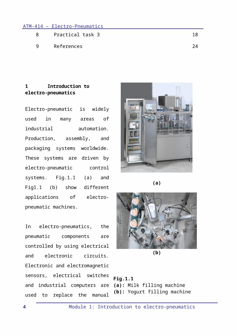
Electro-pneumatic is widely used in many areas of industrial automation. Production, assembly, and packaging systems worldwide. These systems are driven by electro-pneumatic control systems. Fig.1.1 (a) and Fig1.1 (b) show different applications of electro-pneumatic machines.
In electro-pneumatics, the pneumatic components are controlled by using electrical and electronic circuits. Electronic and electromagnetic sensors, electrical switches and industrial computers are used to replace the manual control of a pneumatic system.
(a)
(b)
Fig.1.1(a): Milk filling machine(b): Yogurt filling machine
Module 1: Introduction to electro-pneumatics 3
ATM-414 – Electro-Pneumatics
`2 Signal flow in electro-pneumatic control system
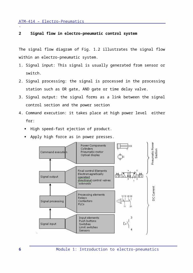
The signal flow diagram of Fig. 1.2 illustrates the signal flow within an electro-pneumatic system.1. Signal input: This signal is usually generated from sensor or switch.2. Signal processing: the signal is processed in the processing station such
as OR gate, AND gate or time delay valve.3. Signal output: the signal forms as a link between the signal control
section and the power section4. Command execution: it takes place at high power level either for:
High speed-fast ejection of product. Apply high force as in power presses.
Fig. 1.2: Signal flow and components of an electro-pneumatic control system
3 Advantages of electro-pneumatic systems:4 Module 1: Introduction to electro-pneumatics
ATM-414 – Pneumatic systems
Below are some advantages of electro-pneumatic systems 1. Greater reliability.
Less moving parts subjected to wear compared to mechanical control systems.
2. Reduced installation complexity.Less components and hoses, leads to less effort in planning and commissioning especially with large and complex systems.
3. The control system can be easily modified and adapted.It is easier to change wiring and modify programs rather than changing mechanical components and hose networks.Example: the AND gate is replaced with logic and through using electrical switches.
4. Easy handling.Less complexity
5. Secure mounting.Fewer hoses
6. Environmentally-friendly coupling system.Less lubrication require
4 Components of electro-pneumatic systemThe electro pneumatic system is normally consists of the following items:1. DC power supply.2. Switches.3. Relays.4. Solenoid valves.5. Sensor.
4.1 DC Power Supply
Module 1: Introduction to electro-pneumatics 5
ATM-414 – Electro-Pneumatics
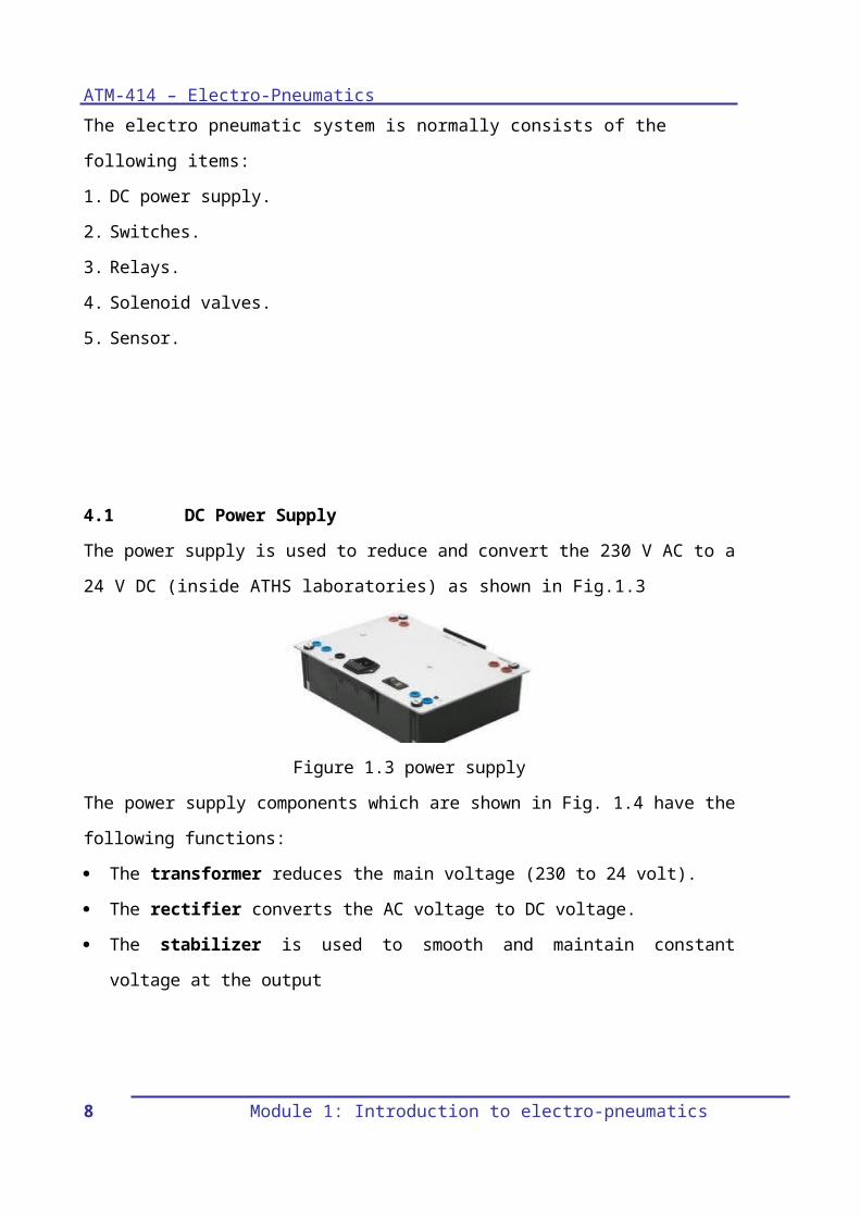
The power supply is used to reduce and convert the 230 V AC to a 24 V DC (inside ATHS laboratories) as shown in Fig.1.3
Figure 1.3 power supplyThe power supply components which are shown in Fig. 1.4 have the following functions: The transformer reduces the main voltage (230 to 24 volt). The rectifier converts the AC voltage to DC voltage. The stabilizer is used to smooth and maintain constant voltage at the
output
Fig.1.4 electric diagram of the power supply
The following criteria play commonly an important role is selecting the power supply:
The magnitude of voltage and current it can supply. How stable its output voltage or current is under varying load
conditions. Whether it provides continuous or pulsed energy.
6 Module 1: Introduction to electro-pneumatics

ATM-414 – Pneumatic systems
4.2 SwitchesSwitches are installed in an electric circuit to connect or interrupt the electric current.These switches are divided into:1- Control switches: keep the selected position such as detent
switches.Push button switches: maintain the selected position as long as the switch is activated.In this module, three types of switches will be discussed:a. Push button switches.b. Detent switches.c. Limit switches.(a) Push button switchesThese switches are activated manually and used connect or disconnect the electric current in he control circuit. There are three typed of the push button switches:
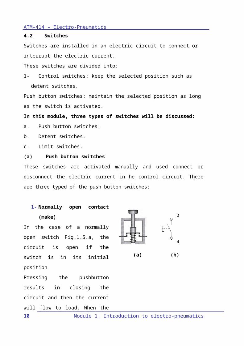
1- Normally open contact (make)
In the case of a normally open switch Fig.1.5.a, the circuit is open if the switch is in its initial position Pressing the pushbutton results in closing the circuit and then the current will flow to load. When the plunger is released the spring will returns the switch to it initial position.
(a) (b)
2 Normally close contact Module 1: Introduction to electro-pneumatics 7
ATM-414 – Electro-Pneumatics
(break)In the case of the normally closed switch Fig. 1.5.c, the circuit is closed when the switch is in its initial position. The circuit is interrupted by pressing the pushbutton. Fig.1.5.d shows the ISO symbol of the push button N/C.
3 Changeover contact (two-way)
The change over contact Fig. 1.9-c combines the function of the normally open and normally closed. Changeover contacts are used to close one circuit and open another circuit in one switching operation.
In the (ATHS) labs, these types of switches are combined in one switch block as illustrated in figure 1.5.g.
(c) (d)
(e) (f)
(g)Fig.1.5: (a): push button switch (N/O)(b): ISO symbol of the normally open push button switch(c): push button switch (N/C)(d): ISO symbol of the normally closed push button switch(e): changeover switch (two way)(f): ISO symbol of the changeover switch(g): Switch block
b Detent switchesThese switches keep the selected
8 Module 1: Introduction to electro-pneumatics
1
2 4

ATM-414 – Pneumatic systems
position; the switch position remains unchanged until a new switch position is selected. It is called detent switch or a latching switch. Fig.1.6.a and Fig.1.6.b show the ISO symbol of the normally open detent switch and normally closed detent switch respectively.Detent switches also designed to be as normally open, normally closed or changeover switches.
In the (ATHS) labs, the detent switches are included in the same switch block with pushbutton switches, as shown in Fig. 1.6.c
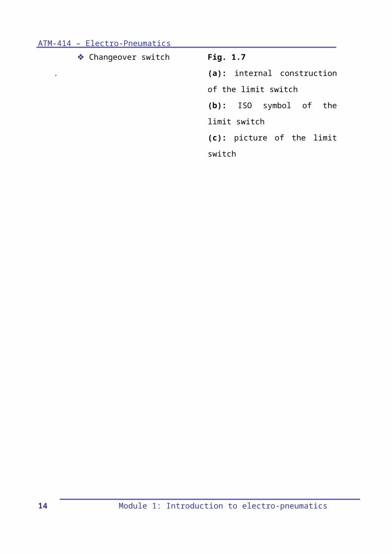
c Limit switchesThe limit switch (Fig.1.7.a) is actuated when a machine part or a work-piece is in a certain position. Normally, actuation is affected by a cam or cylinder piston.
Limit switches are normally changeover contacts and can be connected according to the required control circuit. The limit switch can be used in circuit according to one of the
(a)
(b)
(c)Fig. 1.6: (a): ISO symbol of normally open detent switch(b): ISO symbol of normally closed detent switch(c): Switch block
(a) (b)
Module 1: Introduction to electro-pneumatics 9
ATM-414 – Electro-Pneumatics
following: Normally open switch Normally closed switch Changeover switch
.
Fig. 1.7(a): internal construction of the limit switch(b): ISO symbol of the limit switch(c): picture of the limit switch
10 Module 1: Introduction to electro-pneumatics

ATM-414 – Pneumatic systems
4.3 RelaysA relay is defined as an electromagnetically actuated switch.When the voltage is applied to a solenoid coil terminals (A1, A2) in Fig.1.14, it will become an electromagnet which in turn attracts the contacts of the relay either closing or opening them.The spring returns the contacts to the initial position immediately after disconnecting the voltage at the coil terminals.An ISO symbol of the relay and a lab relay block is also illustrated in the same figure.Some advantages of a relay that: It can be used to switch one or more
contacts. To switch a high current circuit with
a low current circuit.
(a)
(b)
(c)Fig. 1.8:(a): Internal structure(b): ISO symbol of the relay(c): Relay block
Module 1: Introduction to electro-pneumatics 11

ATM-414 – Electro-Pneumatics
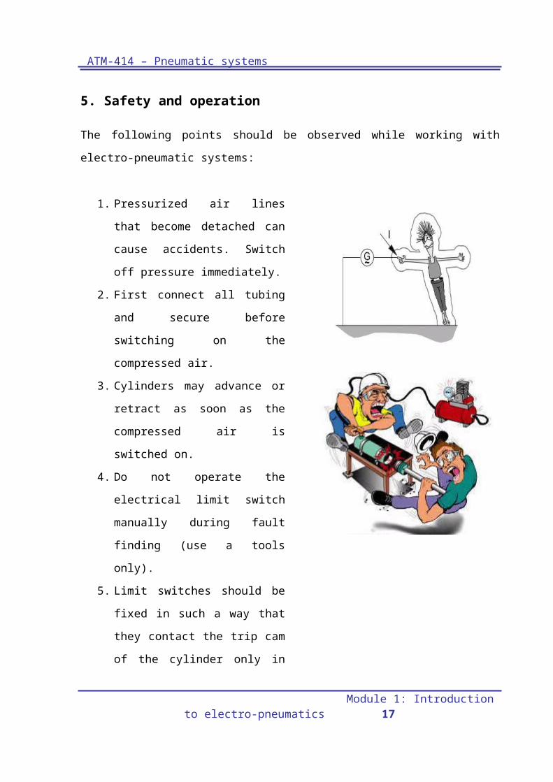
5. Safety and operation
The following points should be observed while working with electro-pneumatic systems:
1. Pressurized air lines that become detached can cause accidents. Switch off pressure immediately.
2. First connect all tubing and secure before switching on the compressed air.
3. Cylinders may advance or retract as soon as the compressed air is switched on.
4. Do not operate the electrical limit switch manually during fault finding (use a tools only).
5. Limit switches should be fixed in such a way that they contact the trip cam of the cylinder only in the determined direction.
6. Do not exceed the permissible working pressure.7. Use only low voltages of ≤ 24 V.8. Switch off the air and voltage supply before disconnecting the
circuit.
12 Module 1: Introduction to electro-pneumatics

ATM-414 – Pneumatic systems
6. Practical Task 1Title:Controlling an electric bulb lighting using different types of switchesObjectives: Understanding and using the DC
power supply. The student should be able to use of
the pushbutton switches (NO and NC).
The student should be able to use of detent switches (NO and NC).
The student should be able to use of changeover switch.
The student should be able to construct the circuit using the FluidSim software
Background:The student should know how to use the Pushbutton, detent and changeover switches that will be used to switch on/off a lamp using different circuit configurations.Required components:
1- DC power supply (Fig.1.9.a)
2- Indicator unit (Fig.1.9.b)
3- Switch block (Fig.1.9 c)
4- Limit switch (Fig1.7
(a)
(b)
(c)
Fig. 1.9:(a): Dc power supply(b): Indicator block(c): Switch block
Module 1: Introduction to electro-pneumatics 13
ATM-414 – Electro-Pneumatics
c)
Procedures:1. Prepare the components according to
the components list.2. From the switch block, use a pushbutton
switch to connect the first two circuits as in Fig.1.10.a Pushbutton switch, normally open.
Press the switch on/off and explain what happens to the lamp. ………………………………………………………………………………………………………………………………………………………………………………………
Pushbutton, Normally closed switch.Press the switch on/off and explain what happens to lamp.……………………………………………………………………………………………………………………………………………………………………………………..
3. From the switch block, use a detent switch to connect the second two circuits as in Fig.1.10.b Detent switch, normally open. Press
the switch and note what happens to the lamp.………………………………………………………………………………………………………………………………………………………………………………………
N.O NC (a)
14 Module 1: Introduction to electro-pneumatics

ATM-414 – Pneumatic systems
Detent switch normally closed. Press the switch and note what happens to the lamp.……………………………………………………………………………………………………………………………………………………………………………………..
4. Use a limit switch (as a changeover switch) to connect the circuit as in Fig.1.10.c
Press the switch and see how the switch is used to control two circuits at a time.Write your comments.……………………………………………………………………………………………………………………………………………………………………………………………………………………………………………………………………………………………………………………………………………………………………………………………………………………………………………………………..
5. Turn the power off. 6. Dismantle and tidy up.
N.O N.C.(b)
(c)
Fig. 1.10:(a): Push button switch(b): Detent switch(c): Changeover switch
Conclusion
............................................................................................................
Module 1: Introduction to electro-pneumatics 15
ATM-414 – Electro-Pneumatics
............................................................................................................
............................................................................................................
............................................................................................................
...........................................................................................................
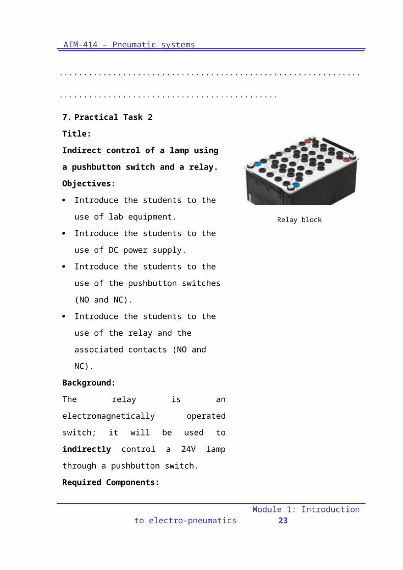
7. Practical Task 2Title:Indirect control of a lamp using a pushbutton switch and a relay.Objectives: Introduce the students to the use of
lab equipment. Introduce the students to the use of
DC power supply. Introduce the students to the use of
the pushbutton switches (NO and NC).
Introduce the students to the use of the relay and the associated contacts (NO and NC).
Background:The relay is an electromagnetically operated switch; it will be used to indirectly control a 24V lamp through a pushbutton switch.Required Components:
5- DC power supply 6- Indicator unit 7- Switch block 8- Relay block
Relay block
16 Module 1: Introduction to electro-pneumatics
ATM-414 – Pneumatic systems
Module 1: Introduction to electro-pneumatics 17
ATM-414 – Electro-Pneumatics
Procedures:
1. Connect the circuit according to circuit shown in Fig.1.11.a, so the relay is a normally open.
2. Switch on /off the pushbutton switch and observe the lamp and also the LED of the relay block. Explain what happens to the lamp?
…………………………………………………………………………………………………………………………………………………………………………………………………..……
3. Replace the pushbutton switch with a detent switch and repeat the same steps. Explain what happens to lamp.
………………………………………………………………………………………………………………………………………………………………………………………………
4. Connect the circuit according to circuit shown in Fig.1.11.b, so the relay is in a normally close mode.
5. Switch on/off the pushbutton switch and observe the lamp and the LED of the relay block. Explain what happens to lamp.
…………………………………………………………….. ……………………………………………………
(a)
(b)
Fig. 1.11:(a): Relay-Normally open
(b): Relay-Normally closed
18 Module 1: Introduction to electro-pneumatics
0V
3
4
K1A1
A2K1
3
4
2
+24V 1 2
+24V
0V
3
4
K2A1
A2K2
1
2
3 4
4

ATM-414 – Pneumatic systems
…………………………………………………………………………
6. Turn off the power
7. Dismantle and tidy up.
Conclusion
............................................................................................................
............................................................................................................
............................................................................................................
............................................................................................................
............................................................................................................
8.Practical Task 3:Title: Opening/closing the flow in a pipelineThe double acting cylinder (1A) in Fig. 1.12 is used to open and close the main valve in a pipeline. Draw an electro-pneumatic circuit to control the movement of cylinder (1A).Hint: The valve is opened by pressing the pushbutton switch. When the pushbutton is released the valve is closed.
Fig. 1.12
Module 1: Introduction to electro-pneumatics 19

ATM-414 – Electro-Pneumatics
20 Module 1: Introduction to electro-pneumatics

ATM-414 – Pneumatic systems
Procedures:
1. Draw the elector-pneumatic circuit using the FluidSim software
2. Test the circuit functions against any errors or mistakes.
3. Construct the circuit on the workstation
4. Write down your notes and observations.
Pneumatic circuit Electric circuit
Observations
............................................................................................................
............................................................................................................
............................................................................................................
............................................................................................................
Module 1: Introduction to electro-pneumatics 21

ATM-414 – Electro-Pneumatics
Student’s notes
............................................................................................................
............................................................................................................
............................................................................................................
............................................................................................................
............................................................................................................
............................................................................................................
............................................................................................................
............................................................................................................
............................................................................................................
............................................................................................................
............................................................................................................
............................................................................................................
............................................................................................................
............................................................................................................
............................................................................................................
............................................................................................................
............................................................................................................
............................................................................................................
............................................................................................................
............................................................................................................
............................................................................................................
............................................................................................................
Class work22 Module 1: Introduction to electro-pneumatics
ATM-414 – Pneumatic systems
1. Name three electrical components that will be used in the lab.………………………………………………………………………………………………………………………………………………………………………………………………………………………………………………………………………………………………………………………………………………………………………
2. What is the function of a D.C. power supply?………………………………………………………………………………………………………………………………………………………………………………………………………………………………………………
3. What are the main components of the D.C. power supply?………………………………………………………………………………………………………………………………………………………………………………………………………………………………………………
4. List the main types of switches in terms of function.………………………………………………………………………………………………………………………………………………………………………………………………………………………………………………………………………………………………………………………………………………………………………
5. Explain the difference between a push button switch and a detent switch.………………………………………………………………………………………………………………………………………………………………………………………………………………………………………………………………………………………………………………………………………………………………………
6. Explain the difference between a pushbutton normally open switch and a pushbutton normally closed switch.………………………………………………………………………………………………
………………………………………………………………………………………………
………………………………………………………………………………………………
……………………………………………………………… Module 1: Introduction to electro-pneumatics 23

ATM-414 – Electro-Pneumatics
………………………………………………………………………………………………
………………………………………………………………………………………………
………………………………………………………………………………………………
………………………………………………………………
7. Draw the ISO symbol of the following components:
a- Detent pushbutton switch, N/C and N/ON/C N/O
b- Changeover switch
c-Relay
24 Module 1: Introduction to electro-pneumatics

ATM-414 – Pneumatic systems
Home Work
The circuit below illustrates a relay controlling three lamps indirectly, answer the following questions:
1. What is the type of switch S1?………………………………………………………………………………………………………………………………………………………………………………………………………………………………………………
2. How many relays are there in the circuit?……………………………………………………………………………………………………………………………………………………………………………………………………………………………………………..
3. What is the meaning of the symbols below circuit 1 and circuit 4?
Module 1: Introduction to electro-pneumatics 25

ATM-414 – Electro-Pneumatics
……………………………………………………………………………………………………………………………………………………………………………………………………………………………………………..
4. Explain what happens when switch S1 is activated.………………………………………………………………………………………………………………………………………………………………………………………………………………………………………………………………………………………………………………………………………………………………………9. References
1. Electro-pneumatic text book TP 201 2005 – Festo
2. Electro-pneumatic work book TP201 2005 – Festo
3. Electro-pneumatic work book TP202 advanced level – Festo
26 Module 1: Introduction to electro-pneumatics