· Web view01 3300 Submittal Procedures Attachment A, Construction Submittal Log Instructions to...
129
01 3300, Submittal Procedures Attachment A, Construction Submittal Log Rev. June 29, 2015 01 3300 Submittal Procedures Attachment A, Construction Submittal Log ********************************************************************************* ********************************************* Instructions to Users 1. This Section/Attachment is now required for all LANL projects utilizing specifications in lieu of the technical and quality submittals listing being in Exhibit I , Subcontractor Submittal Requirements, the pro forma (boilerplate-like) document. 2. The design agency must tailor this template to provide the combined technical and quality related input from the specs. In order to tailor and complete this input template: Items (rows) not applicable to a particular project or acquisition must be deleted. Rows consolidated (hammocking) -- (note, the resulting “bundling” may cause complications in accepting/rejecting/tracking acceptability of submittals) Additional rows added for spec sections and their submittals created by the design agency. Template entries validated The need for concurrent reviews [and LANS Reviewer(s)] finalized with input from LANL Project Engineer (after PE resolves with LANL ES-EPD, see below) Sequential numbering of submittals finalized. If desiring to use suffixes or other method to indicate submittals to be sent in together, then the column’s automated pre-numbered set-up can be deleted/overwritten. “Submittal Schedule” Column (Design Agency Responsibilities): Note: When a LANL Master Spec (LMS) Section explicitly sets time-of-submittal, this column should match. When the LMS Section is mute, template data reflects Standards Program best judgment. 1. At point of Project Spec issuance, schedule must match all Section expectations. 2. Modification of submittal timing at any time is not a design change but is administrative (perhaps with schedule, technical, and/or quality impacts, positive or negative). 3. Modification of template prior to award to constructor: Changes from norm shall be highlighted to reviewers using redline/strikeout (preferred), possibly color. If template update for future project benefit is appropriate, suggest to Standards Manager along with whether LMS Section is suboptimal. 4. Modification after award should be managed by SDDR; when concurrent or consecutive review was required, engage PE to involve appropriate reviews of timing change. Contract mod may be required. Again, not design change (e.g., FCR, FCN) per se, but such processes may be employed if desired. Page 1 of 129
Transcript of · Web view01 3300 Submittal Procedures Attachment A, Construction Submittal Log Instructions to...

01 3300, Submittal ProceduresAttachment A, Construction Submittal Log Rev. June 29, 2015
01 3300 Submittal ProceduresAttachment A, Construction Submittal Log
******************************************************************************************************************************Instructions to Users
1. This Section/Attachment is now required for all LANL projects utilizing specifications in lieu of the technical and quality submittals listing being in Exhibit I, Subcontractor Submittal Requirements, the pro forma (boilerplate-like) document.
2. The design agency must tailor this template to provide the combined technical and quality related input from the specs. In order to tailor and complete this input template: Items (rows) not applicable to a particular project or acquisition must be deleted. Rows consolidated (hammocking) -- (note, the resulting “bundling” may cause complications in
accepting/rejecting/tracking acceptability of submittals) Additional rows added for spec sections and their submittals created by the design agency. Template entries validated The need for concurrent reviews [and LANS Reviewer(s)] finalized with input from LANL Project
Engineer (after PE resolves with LANL ES-EPD, see below) Sequential numbering of submittals finalized. If desiring to use suffixes or other method to indicate
submittals to be sent in together, then the column’s automated pre-numbered set-up can be deleted/overwritten.
“Submittal Schedule” Column (Design Agency Responsibilities): Note: When a LANL Master Spec (LMS) Section explicitly sets time-of-submittal, this column should match. When the LMS Section is mute, template data reflects Standards Program best judgment.
1. At point of Project Spec issuance, schedule must match all Section expectations.2. Modification of submittal timing at any time is not a design change but is administrative (perhaps with
schedule, technical, and/or quality impacts, positive or negative).3. Modification of template prior to award to constructor: Changes from norm shall be highlighted to
reviewers using redline/strikeout (preferred), possibly color. If template update for future project benefit is appropriate, suggest to Standards Manager along with whether LMS Section is suboptimal.
4. Modification after award should be managed by SDDR; when concurrent or consecutive review was required, engage PE to involve appropriate reviews of timing change. Contract mod may be required. Again, not design change (e.g., FCR, FCN) per se, but such processes may be employed if desired.
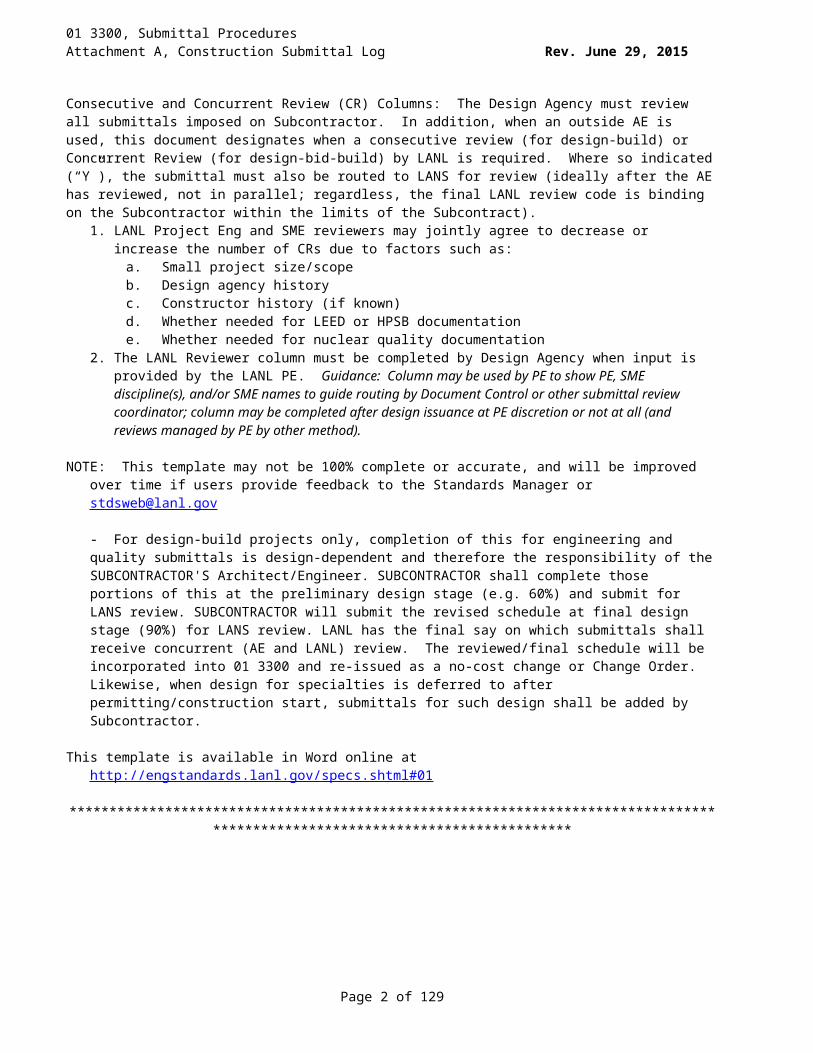
Consecutive and Concurrent Review (CR) Columns: The Design Agency must review all submittals imposed on Subcontractor. In addition, when an outside AE is used, this document designates when a consecutive review (for design-build) or Concurrent Review (for design-bid-build) by LANL is required. Where so indicated (“Y”), the submittal must also be routed to LANS for review (ideally after the AE has reviewed, not in parallel; regardless, the final LANL review code is binding on the Subcontractor within the limits of the Subcontract).
1. LANL Project Eng and SME reviewers may jointly agree to decrease or increase the number of CRs due to factors such as:
a. Small project size/scopeb. Design agency historyc. Constructor history (if known)d. Whether needed for LEED or HPSB documentatione. Whether needed for nuclear quality documentation
2. The LANL Reviewer column must be completed by Design Agency when input is provided by the LANL PE. Guidance: Column may be used by PE to show PE, SME discipline(s), and/or SME names to guide routing by Document Control or other submittal review coordinator; column may be completed after design issuance at PE discretion or not at all (and reviews managed by PE by other method).
NOTE: This template may not be 100% complete or accurate, and will be improved over time if users provide feedback to the Standards Manager or [email protected]
Page 1 of 83
01 3300, Submittal ProceduresAttachment A, Construction Submittal Log Rev. June 29, 2015
- For design-build projects only, completion of this for engineering and quality submittals is design-dependent and therefore the responsibility of the SUBCONTRACTOR'S Architect/Engineer. SUBCONTRACTOR shall complete those portions of this at the preliminary design stage (e.g. 60%) and submit for LANS review. SUBCONTRACTOR will submit the revised schedule at final design stage (90%) for LANS review. LANL has the final say on which submittals shall receive concurrent (AE and LANL) review. The reviewed/final schedule will be incorporated into 01 3300 and re-issued as a no-cost change or Change Order.Likewise, when design for specialties is deferred to after permitting/construction start, submittals for such design shall be added by Subcontractor.
This template is available in Word online at http://engstandards.lanl.gov/specs.shtml#01
******************************************************************************************************************************
Page 2 of 83
01 3300, Submittal ProceduresAttachment A, Construction Submittal Log Rev. June 29, 2015
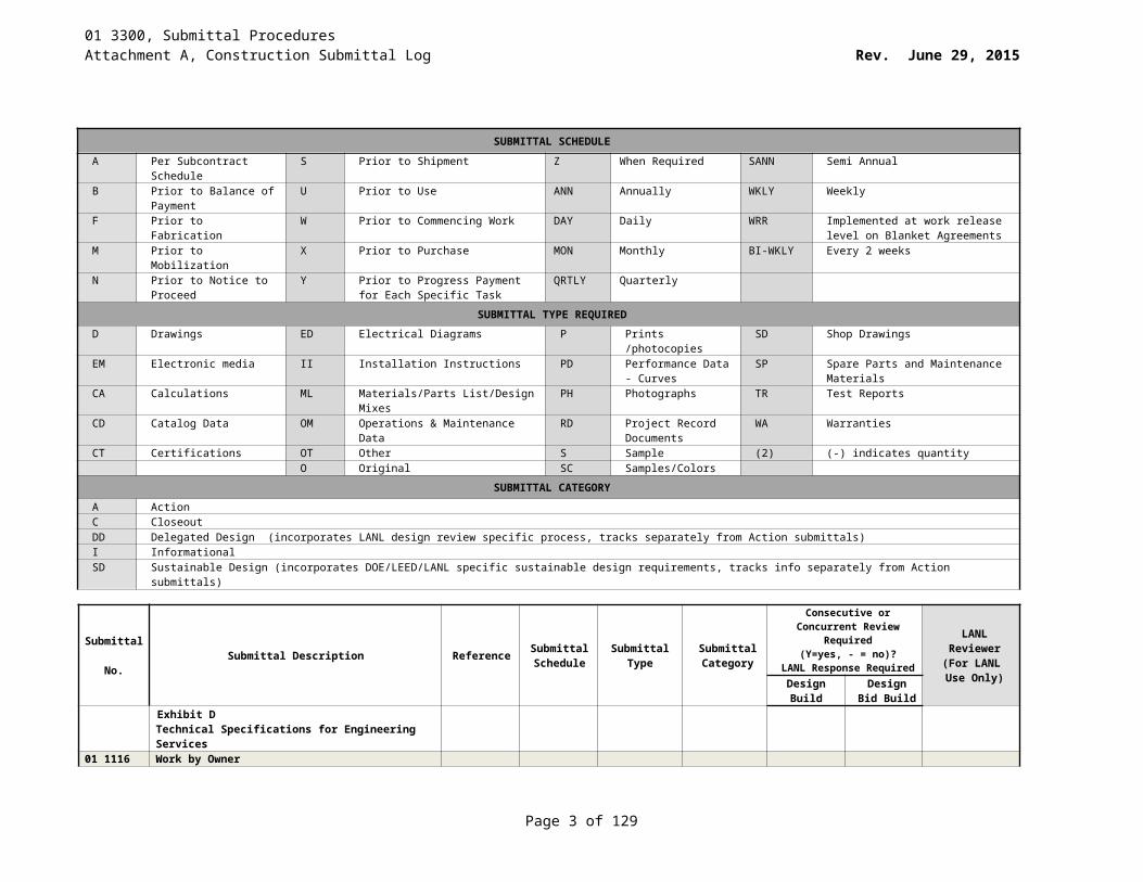
SUBMITTAL SCHEDULEA Per Subcontract Schedule S Prior to Shipment Z When Required SANN Semi AnnualB Prior to Balance of
PaymentU Prior to Use ANN Annually WKLY Weekly
F Prior to Fabrication W Prior to Commencing Work DAY Daily WRR Implemented at work release level on Blanket Agreements
M Prior to Mobilization X Prior to Purchase MON Monthly BI-WKLY Every 2 weeksN Prior to Notice to Proceed Y Prior to Progress Payment for Each
Specific TaskQRTLY Quarterly
SUBMITTAL TYPE REQUIREDD Drawings ED Electrical Diagrams P Prints /photocopies SD Shop DrawingsEM Electronic media II Installation Instructions PD Performance Data -
CurvesSP Spare Parts and Maintenance
MaterialsCA Calculations ML Materials/Parts List/Design Mixes PH Photographs TR Test ReportsCD Catalog Data OM Operations & Maintenance Data RD Project Record
DocumentsWA Warranties
CT Certifications OT Other S Sample (2) (-) indicates quantityO Original SC Samples/Colors
SUBMITTAL CATEGORYA Action C CloseoutDD Delegated Design (incorporates LANL design review specific process, tracks separately from Action submittals)I InformationalSD Sustainable Design (incorporates DOE/LEED/LANL specific sustainable design requirements, tracks info separately from Action submittals)
Submittal No. Submittal Description Reference Submittal
ScheduleSubmittal
TypeSubmittal Category
Consecutive or Concurrent Review Required (Y=yes, - = no)?
LANL Response Required
LANL Reviewer
(For LANL Use Only)Design
BuildDesign Bid
BuildExhibit D Technical Specifications for Engineering Services
01 1116 Work by OwnerN/A
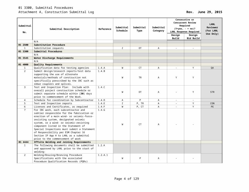
01 2500 Substitution Procedure1 Substitution requests Z OT A - -
01 3300 Submittal ProceduresN/A
01 3545 Water Discharge RequirementsN/A
01 4000 Quality Requirements1 Qualification data for testing agencies 1.4.A W CT A - Y QA2 Submit design/research reports/test data supporting the
use of alternate materials/methods of construction not specifically prescribed by the IBC such as rebar couplers and splices.
1.4.B
W TR A Y Y
3 Test and Inspection Plan: Include with overall project construction schedule or submit separate schedule within [30] days prior to commencement of the Work.
1.4.CW OT A - Y STR
Page 3 of 83
01 3300, Submittal ProceduresAttachment A, Construction Submittal Log Rev. June 29, 2015
Submittal No. Submittal Description Reference Submittal
ScheduleSubmittal
TypeSubmittal Category
Consecutive or Concurrent Review Required (Y=yes, - = no)?
LANL Response Required
LANL Reviewer
(For LANL Use Only)Design
BuildDesign Bid
Build4 Schedule for coordination by Subcontractor 1.4.D A P A - -5 Test and Inspection reports 1.4.E Z P, TR A - Y CON6 Licenses and Certificates, as required 1.4.F W P, CT A - Y PE7 For IBC work, each subcontractor and subtier responsible
for the fabrication or erection of a main wind- or seismic-force-resisting system, designated seismic system, or a wind- or seismic-resisting component listed in the Statement of Special Inspections must submit a Statement of Responsibility per ESM Chapter 16 Section IP App H to LANL as a submittal prior to the commencement of work
1.4.G
W CT A - -
01 4444 Offsite Welding and Joining Requirements1 The following documents shall be submitted and
approved by LANL prior to the start of welding:1.2.A
2 Welding/Brazing/Bronzing Procedure Specifications with the associated Procedure Qualification Records (PQRs)
1.2.A.1 W P A - -
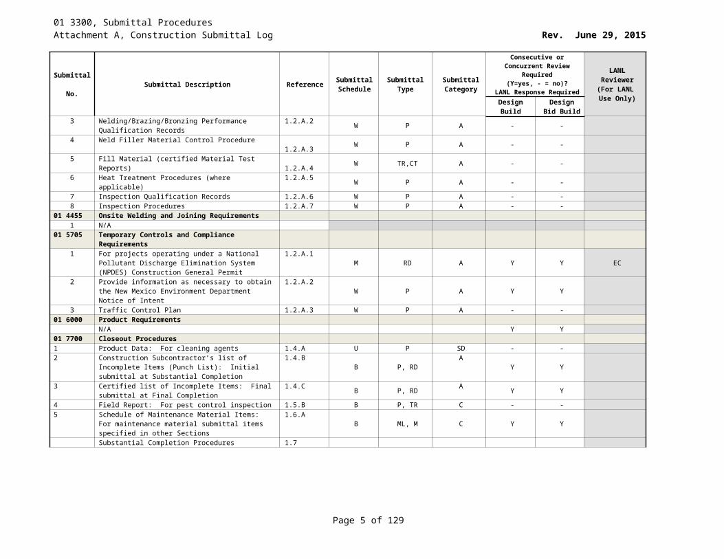
3 Welding/Brazing/Bronzing Performance Qualification Records
1.2.A.2 W P A - -
4 Weld Filler Material Control Procedure1.2.A.3 W P A - -
5 Fill Material (certified Material Test Reports)1.2.A.4 W TR,CT A - -
6 Heat Treatment Procedures (where applicable) 1.2.A.5 W P A - -7 Inspection Qualification Records 1.2.A.6 W P A - -8 Inspection Procedures 1.2.A.7 W P A - -
01 4455 Onsite Welding and Joining Requirements1 N/A
01 5705 Temporary Controls and Compliance Requirements1 For projects operating under a National Pollutant
Discharge Elimination System (NPDES) Construction General Permit
1.2.A.1M RD A Y Y EC
2 Provide information as necessary to obtain the New Mexico Environment Department Notice of Intent
1.2.A.2 W P A Y Y
3 Traffic Control Plan 1.2.A.3 W P A - -01 6000 Product Requirements
N/A Y Y01 7700 Closeout Procedures
1 Product Data: For cleaning agents 1.4.A U P SD - -2 Construction Subcontractor’s list of Incomplete Items
(Punch List): Initial submittal at Substantial Completion1.4.B B P, RD A Y Y
3 Certified list of Incomplete Items: Final submittal at Final Completion
1.4.C B P, RD A Y Y
4 Field Report: For pest control inspection 1.5.B B P, TR C - -5 Schedule of Maintenance Material Items: For
maintenance material submittal items specified in other Sections
1.6.AB ML, M C Y Y
Substantial Completion Procedures 1.7
Page 4 of 83
01 3300, Submittal ProceduresAttachment A, Construction Submittal Log Rev. June 29, 2015
Submittal No. Submittal Description Reference Submittal
ScheduleSubmittal
TypeSubmittal Category
Consecutive or Concurrent Review Required (Y=yes, - = no)?
LANL Response Required
LANL Reviewer
(For LANL Use Only)Design
BuildDesign Bid
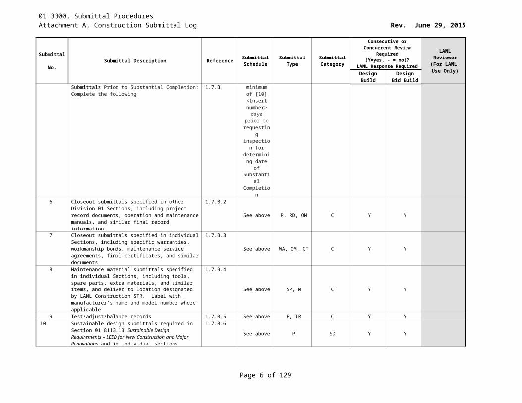
BuildSubmittals Prior to Substantial Completion: Complete the following
1.7.B minimum of [10] <Insert number> days prior
to requesting inspection
for determining
date of Substantial Completion
6 Closeout submittals specified in other Division 01 Sections, including project record documents, operation and maintenance manuals, and similar final record information
1.7.B.2
See above P, RD, OM C Y Y
7 Closeout submittals specified in individual Sections, including specific warranties, workmanship bonds, maintenance service agreements, final certificates, and similar documents
1.7.B.3
See above WA, OM, CT C Y Y
8 Maintenance material submittals specified in individual Sections, including tools, spare parts, extra materials, and similar items, and deliver to location designated by LANL Construction STR. Label with manufacturer’s name and model number where applicable
1.7.B.4
See above SP, M C Y Y
9 Test/adjust/balance records 1.7.B.5 See above P, TR C Y Y10 Sustainable design submittals required in Section 01
8113.13 Sustainable Design Requirements – LEED for New Construction and Major Renovations and in individual sections
1.7.B.6
See above P SD Y Y
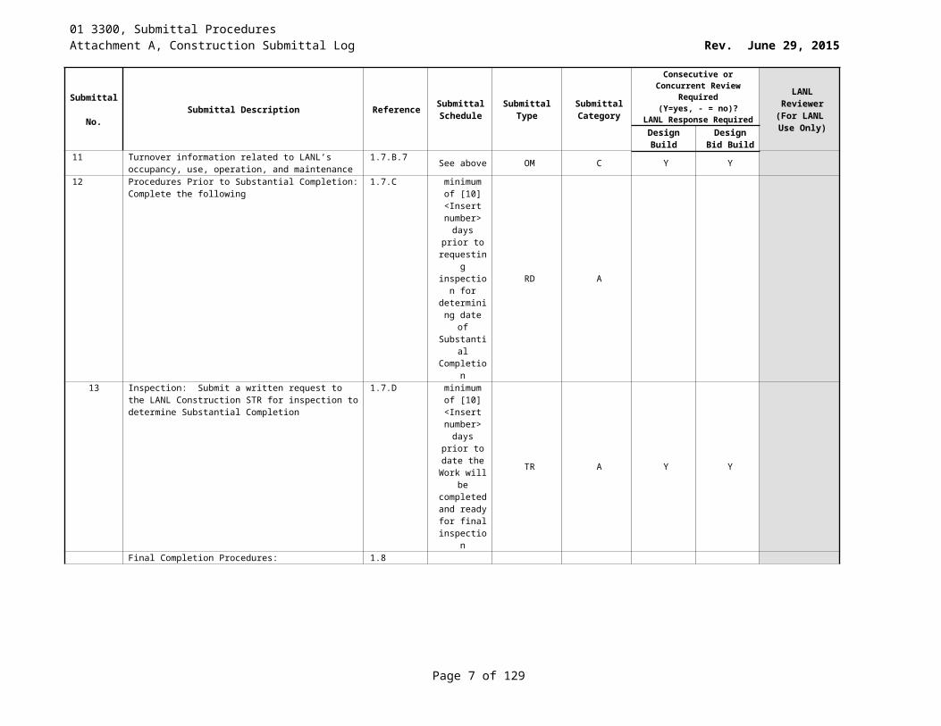
11 Turnover information related to LANL’s occupancy, use, operation, and maintenance
1.7.B.7 See above OM C Y Y
12 Procedures Prior to Substantial Completion: Complete the following
1.7.C minimum of [10] <Insert number> days prior
to requesting inspection
for determining
date of Substantial Completion
RD A
Page 5 of 83
01 3300, Submittal ProceduresAttachment A, Construction Submittal Log Rev. June 29, 2015
Submittal No. Submittal Description Reference Submittal
ScheduleSubmittal
TypeSubmittal Category
Consecutive or Concurrent Review Required (Y=yes, - = no)?
LANL Response Required
LANL Reviewer
(For LANL Use Only)Design
BuildDesign Bid
Build13 Inspection: Submit a written request to the LANL
Construction STR for inspection to determine Substantial Completion
1.7.D minimum of [10] <Insert number> days prior to date the
Work will be completed and ready
for final inspection
TR A Y Y
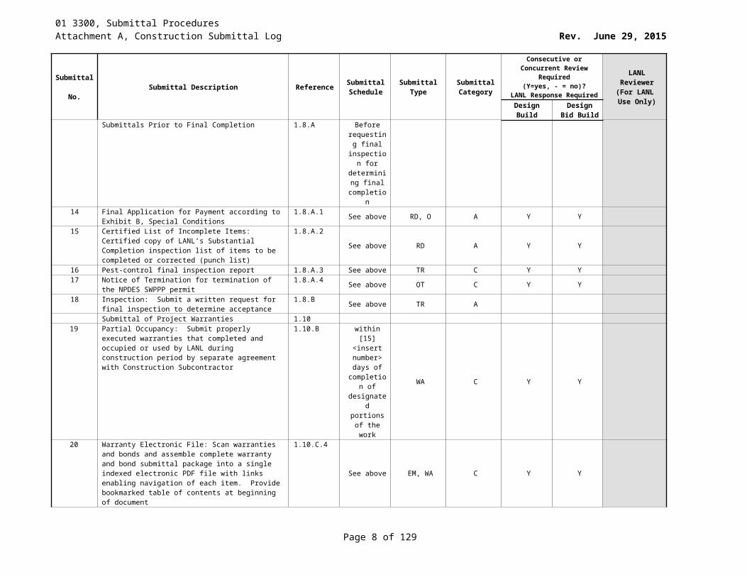
Final Completion Procedures: 1.8Submittals Prior to Final Completion 1.8.A Before
requesting final
inspection for
determining final
completion14 Final Application for Payment according to Exhibit B,
Special Conditions1.8.A.1 See above RD, O A Y Y
15 Certified List of Incomplete Items: Certified copy of LANL’s Substantial Completion inspection list of items to be completed or corrected (punch list)
1.8.A.2See above RD A Y Y
16 Pest-control final inspection report 1.8.A.3 See above TR C Y Y17 Notice of Termination for termination of the NPDES
SWPPP permit1.8.A.4 See above OT C Y Y
18 Inspection: Submit a written request for final inspection to determine acceptance
1.8.B See above TR A
Submittal of Project Warranties 1.1019 Partial Occupancy: Submit properly executed warranties
that completed and occupied or used by LANL during construction period by separate agreement with Construction Subcontractor
1.10.B within [15] <insert
number> days of
completion of
designated portions of the work
WA C Y Y
20 Warranty Electronic File: Scan warranties and bonds and assemble complete warranty and bond submittal package into a single indexed electronic PDF file with links enabling navigation of each item. Provide bookmarked table of contents at beginning of document
1.10.C.4
See above EM, WA C Y Y
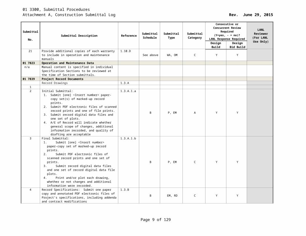
21 Provide additional copies of each warranty to include in operation and maintenance manuals
1.10.D See above WA, OM C Y Y
Page 6 of 83
01 3300, Submittal ProceduresAttachment A, Construction Submittal Log Rev. June 29, 2015
Submittal No. Submittal Description Reference Submittal
ScheduleSubmittal
TypeSubmittal Category
Consecutive or Concurrent Review Required (Y=yes, - = no)?
LANL Response Required
LANL Reviewer
(For LANL Use Only)Design
BuildDesign Bid
Build01 7823 Operation and Maintenance Data
n/a Manual content is specified in individual Specification Sections to be reviewed at the time of Section submittals.
01 7839 Project Record DocumentsRecord Drawings 1.3.A
12 Initial Submittal:
1. Submit [one] <Insert number> paper-copy set(s) of marked-up record prints.
2. Submit PDF electronic files of scanned record prints and one of file prints.
3. Submit record digital data files and one set of plots.4. A/E of Record will indicate whether general scope
of changes, additional information recorded, and quality of drafting are acceptable
1.3.A.1.a
B P, EM A Y Y
3 Final Submittal:1. Submit [one] <Insert number> paper-copy set of
marked-up record prints.2. Submit PDF electronic files of scanned record prints
and one set of prints.3. Submit record digital data files and one set of record
digital data file plots.4. Print and/or plot each drawing, whether or not
changes and additional information were recorded.
1.3.A.1.b
B P, EM C Y Y
4 Record Specifications: Submit one paper copy and annotated PDF electronic files of Project’s specifications, including addenda and contract modifications
1.3.BB EM, RD C Y Y
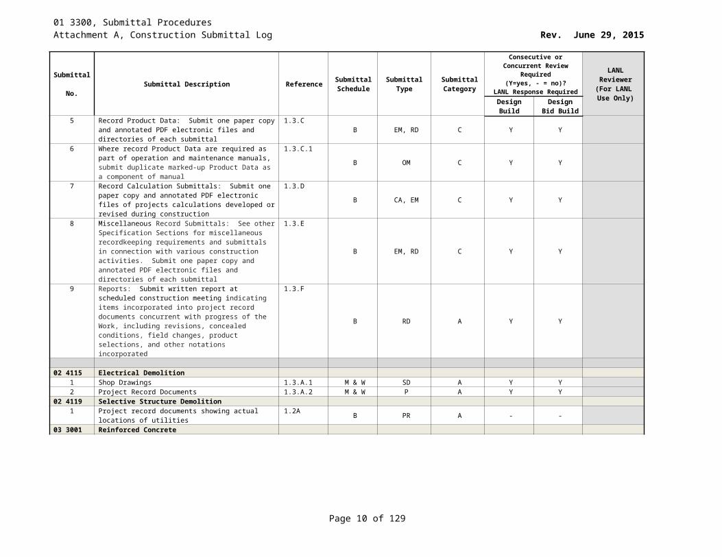
5 Record Product Data: Submit one paper copy and annotated PDF electronic files and directories of each submittal
1.3.CB EM, RD C Y Y
6 Where record Product Data are required as part of operation and maintenance manuals, submit duplicate marked-up Product Data as a component of manual
1.3.C.1B OM C Y Y
7 Record Calculation Submittals: Submit one paper copy and annotated PDF electronic files of projects calculations developed or revised during construction
1.3.DB CA, EM C Y Y
8 Miscellaneous Record Submittals: See other Specification Sections for miscellaneous recordkeeping requirements and submittals in connection with various construction activities. Submit one paper copy and annotated PDF electronic files and directories of each submittal
1.3.E
B EM, RD C Y Y
9 Reports: Submit written report at scheduled construction meeting indicating items incorporated into project record documents concurrent with progress of the Work, including revisions, concealed conditions, field changes, product selections, and other notations incorporated
1.3.F
B RD A Y Y
02 4115 Electrical Demolition1 Shop Drawings 1.3.A.1 M & W SD A Y Y
Page 7 of 83
01 3300, Submittal ProceduresAttachment A, Construction Submittal Log Rev. June 29, 2015
Submittal No. Submittal Description Reference Submittal
ScheduleSubmittal
TypeSubmittal Category
Consecutive or Concurrent Review Required (Y=yes, - = no)?
LANL Response Required
LANL Reviewer
(For LANL Use Only)Design
BuildDesign Bid
Build2 Project Record Documents 1.3.A.2 M & W P A Y Y
02 4119 Selective Structure Demolition1 Project record documents showing actual locations of
utilities1.2A B PR A - -
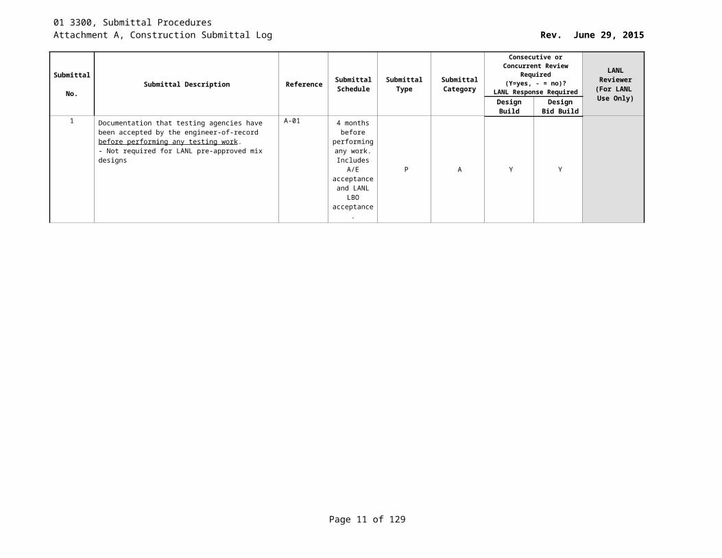
03 3001 Reinforced Concrete1 Documentation that testing agencies have been accepted
by the engineer-of-record before performing any testing work.- Not required for LANL pre-approved mix designs
A-01 4 months before
performing any work.
Includes A/E acceptance and LANL
LBO acceptance.
P A Y Y
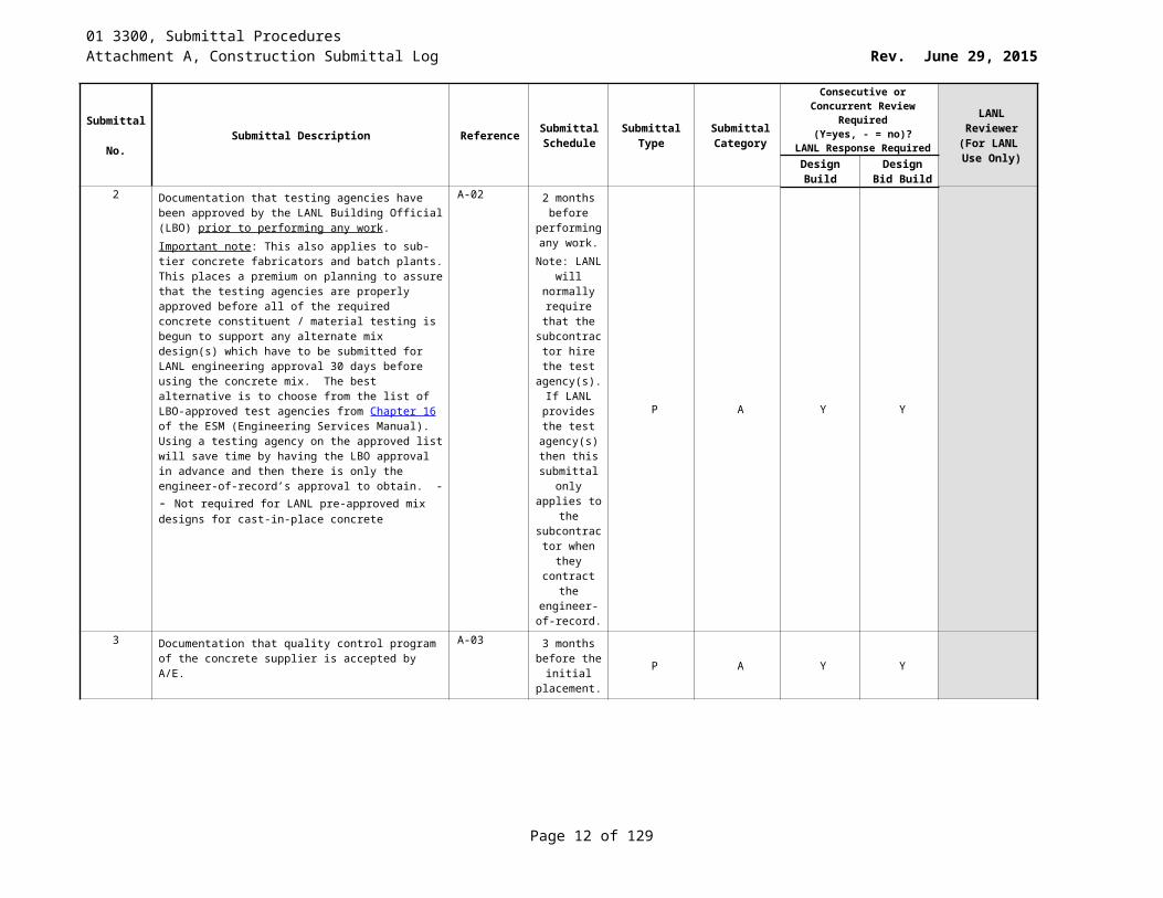
2 Documentation that testing agencies have been approved by the LANL Building Official (LBO) prior to performing any work. Important note: This also applies to sub-tier concrete fabricators and batch plants. This places a premium on planning to assure that the testing agencies are properly approved before all of the required concrete constituent / material testing is begun to support any alternate mix design(s) which have to be submitted for LANL engineering approval 30 days before using the concrete mix. The best alternative is to choose from the list of LBO-approved test agencies from Chapter 16 of the ESM (Engineering Services Manual). Using a testing agency on the approved list will save time by having the LBO approval in advance and then there is only the engineer-of-record’s approval to obtain. -- Not required for LANL pre-approved mix designs for cast-in-place concrete
A-02 2 months before
performing any work.
Note: LANL will normally require that
the subcontractor hire the test agency(s). If
LANL provides the
test agency(s) then this submittal
only applies to the
subcontractor when they contract the engineer-of-
record.
P A Y Y
3 Documentation that quality control program of the concrete supplier is accepted by A/E.
A-03 3 months before the
initial placement.
P A Y Y
Page 8 of 83
01 3300, Submittal ProceduresAttachment A, Construction Submittal Log Rev. June 29, 2015
Submittal No. Submittal Description Reference Submittal
ScheduleSubmittal
TypeSubmittal Category
Consecutive or Concurrent Review Required (Y=yes, - = no)?
LANL Response Required
LANL Reviewer
(For LANL Use Only)Design
BuildDesign Bid
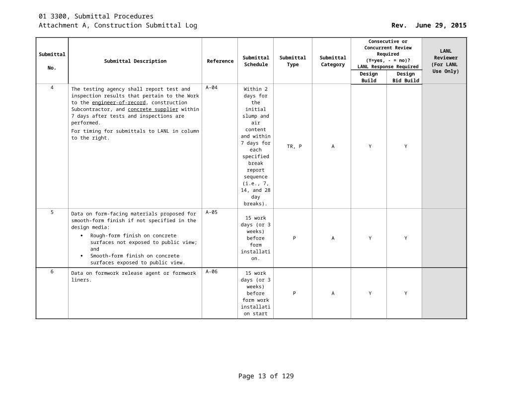
Build4 The testing agency shall report test and inspection results
that pertain to the Work to the engineer-of-record, construction Subcontractor, and concrete supplier within 7 days after tests and inspections are performed. For timing for submittals to LANL in column to the right.
A-04 Within 2 days for the initial
slump and air content and
within 7 days for each specified
break report sequence (i.e., 7, 14, and 28 day
breaks).
TR, P A Y Y
5 Data on form-facing materials proposed for smooth-form finish if not specified in the design media:
Rough-form finish on concrete surfaces not exposed to public view; and
Smooth-form finish on concrete surfaces exposed to public view.
A-05
15 work days (or 3 weeks) before form installation.
P A Y Y
6 Data on formwork release agent or formwork liners. A-06 15 work days (or 3 weeks) before form
work installation
start
P A Y Y
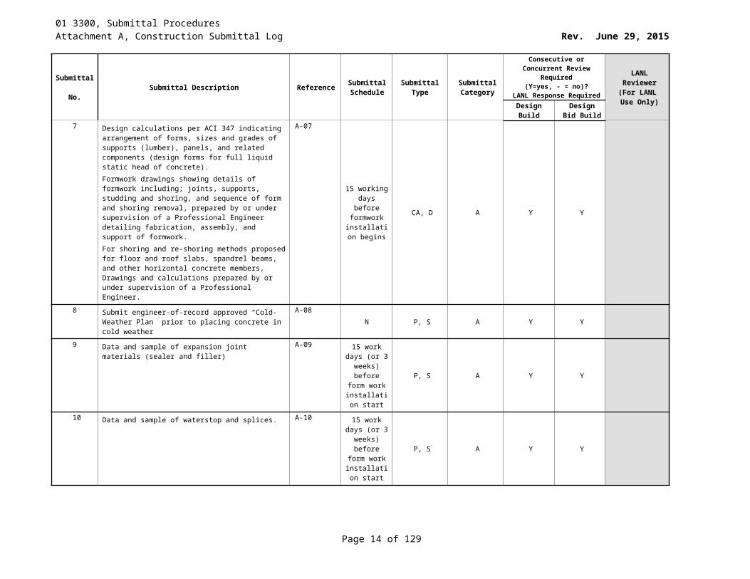
7 Design calculations per ACI 347 indicating arrangement of forms, sizes and grades of supports (lumber), panels, and related components (design forms for full liquid static head of concrete). Formwork drawings showing details of formwork including; joints, supports, studding and shoring, and sequence of form and shoring removal, prepared by or under supervision of a Professional Engineer detailing fabrication, assembly, and support of formwork.For shoring and re-shoring methods proposed for floor and roof slabs, spandrel beams, and other horizontal concrete members, Drawings and calculations prepared by or under supervision of a Professional Engineer.
A-07
15 working days before
formwork installation
begins
CA, D A Y Y
8 Submit engineer-of-record approved “Cold-Weather Plan” prior to placing concrete in cold weather
A-08N P, S A Y Y
9 Data and sample of expansion joint materials (sealer and filler)
A-09 15 work days (or 3 weeks) before form
work installation
start
P, S A Y Y
Page 9 of 83
01 3300, Submittal ProceduresAttachment A, Construction Submittal Log Rev. June 29, 2015
Submittal No. Submittal Description Reference Submittal
ScheduleSubmittal
TypeSubmittal Category
Consecutive or Concurrent Review Required (Y=yes, - = no)?
LANL Response Required
LANL Reviewer
(For LANL Use Only)Design
BuildDesign Bid
Build10 Data and sample of waterstop and splices. A-10 15 work days
(or 3 weeks) before form
work installation
start
P, S A Y Y
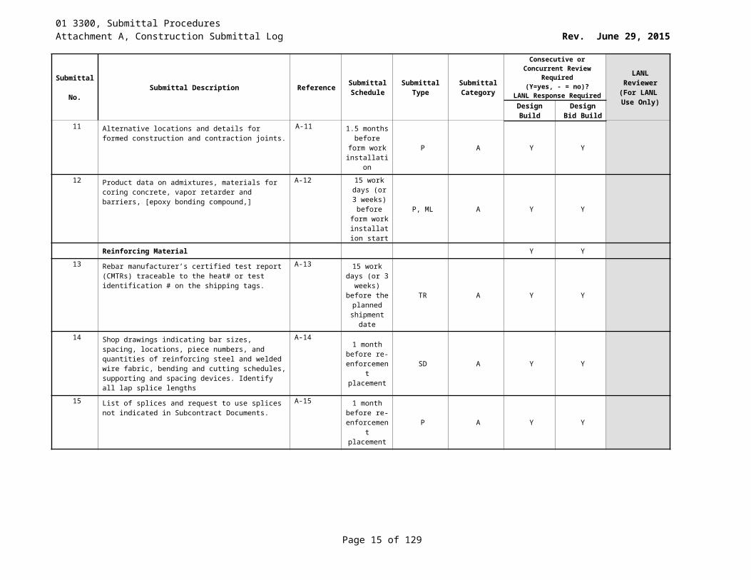
11 Alternative locations and details for formed construction and contraction joints.
A-11 1.5 months before form
work installation
P A Y Y
12 Product data on admixtures, materials for coring concrete, vapor retarder and barriers, [epoxy bonding compound,]
A-12 15 work days (or 3
weeks) before form
work installation
start
P, ML A Y Y
Reinforcing Material Y Y
13 Rebar manufacturer’s certified test report (CMTRs) traceable to the heat# or test identification # on the shipping tags.
A-13 15 work days (or 3 weeks) before the planned shipment
date
TR A Y Y
14 Shop drawings indicating bar sizes, spacing, locations, piece numbers, and quantities of reinforcing steel and welded wire fabric, bending and cutting schedules, supporting and spacing devices. Identify all lap splice lengths
A-141 month
before re-enforcement placement
SD A Y Y
15 List of splices and request to use splices not indicated in Subcontract Documents.
A-15 1 month before re-
enforcement placement
P A Y Y
16 Request to use mechanical splices not shown on the project drawings. In addition, submit the ICC Evaluation Report(s) showing the requested mechanical splices to meet the requirements of ACI 318/ACI 355.2 for the IBC year edition applicable for the project. ACI 301-[2005] paragraph 3.1.1.1.d (and ACI 355.2 section 12) requiring objective evidence that ICC (the evaluation agency) has approved the mechanical splice for use under IBC (year edition applicable).
A-16
1 month before re-
enforcement placement
OT A Y Y
Page 10 of 83
01 3300, Submittal ProceduresAttachment A, Construction Submittal Log Rev. June 29, 2015
Submittal No. Submittal Description Reference Submittal
ScheduleSubmittal
TypeSubmittal Category
Consecutive or Concurrent Review Required (Y=yes, - = no)?
LANL Response Required
LANL Reviewer
(For LANL Use Only)Design
BuildDesign Bid
Build17 Request and procedure to field bend or straighten
reinforcement partially embedded in concrete.A-17 15 work days
(or 3 weeks) prior to
placement of reinforcemen
t
P, OT A Y Y
18 Copy of current CRSI Plant Certification for any reinforcement manufacturer’s plant. . If the epoxy coated rebar facility is not CRSI certified then the inspection and quality control program of the plant applying the epoxy coating.
A-18 15 work days (or 3 weeks) before the planned shipment
date.
P, CT A Y Y
19 If coated reinforcement is required, description of reinforcement supports and materials for fastening coated reinforcement not described in 3.3.2.4 of ACI 305-05 (later edition if applicable)
A-19 15 work days (or 3 weeks)
before placement of reinforcemen
t
P A Y Y
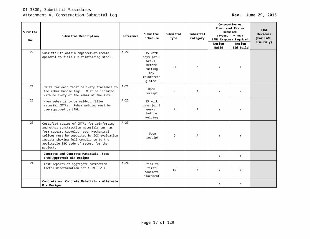
20 Submittal to obtain engineer-of-record approval to field-cut reinforcing steel.
A-20 15 work days (or 3 weeks)
before cutting any reinforcing
steel
OT A Y Y
21 CMTRs for each rebar delivery traceable to the rebar bundle tags. Must be included with delivery of the rebar at the site.
A-21Upon receipt P A Y Y
22 When rebar is to be welded, filler material CMTRs. Rebar welding must be pre-approved by LANL.
A-22 15 work days (or 3 weeks)
before welding
P A Y Y
23 Certified copies of CMTRs for reinforcing and other construction materials such as form savers, cadwelds, etc. Mechanical splices must be supported by ICC evaluation reports showing full compliance to the applicable IBC code of record for the project.
A-23
Upon receipt O A Y Y
Concrete and Concrete Materials –Spec (Pre-Approved) Mix Designs Y Y
24 Test reports of aggregate correction factor determination per ASTM C 231.
A-24 Prior to first concrete
placement TR A Y Y
Concrete and Concrete Materials – Alternate Mix Designs Y Y
Page 11 of 83
01 3300, Submittal ProceduresAttachment A, Construction Submittal Log Rev. June 29, 2015
Submittal No. Submittal Description Reference Submittal
ScheduleSubmittal
TypeSubmittal Category
Consecutive or Concurrent Review Required (Y=yes, - = no)?
LANL Response Required
LANL Reviewer
(For LANL Use Only)Design
BuildDesign Bid
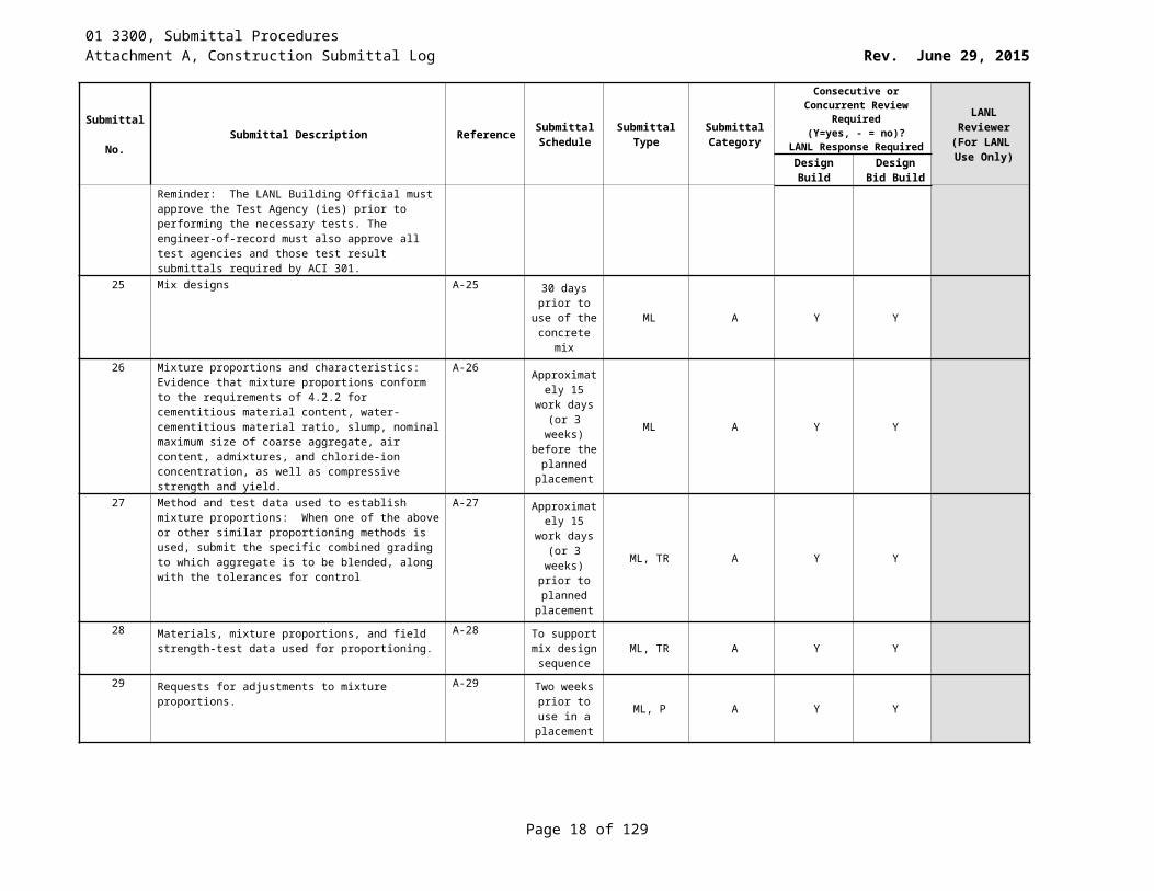
BuildReminder: The LANL Building Official must approve the Test Agency (ies) prior to performing the necessary tests. The engineer-of-record must also approve all test agencies and those test result submittals required by ACI 301.
25 Mix designs A-25 30 days prior to use of the concrete mix
ML A Y Y
26 Mixture proportions and characteristics: Evidence that mixture proportions conform to the requirements of 4.2.2 for cementitious material content, water-cementitious material ratio, slump, nominal maximum size of coarse aggregate, air content, admixtures, and chloride-ion concentration, as well as compressive strength and yield.
A-26 Approximately 15 work days (or 3
weeks) before the planned
placement
ML A Y Y
27 Method and test data used to establish mixture proportions: When one of the above or other similar proportioning methods is used, submit the specific combined grading to which aggregate is to be blended, along with the tolerances for control
A-27 Approximately 15 work days (or 3
weeks) prior to planned placement
ML, TR A Y Y
28 Materials, mixture proportions, and field strength-test data used for proportioning.
A-28 To support mix design sequence
ML, TR A Y Y
29 Requests for adjustments to mixture proportions. A-29 Two weeks prior to use
in a placement
ML, P A Y Y
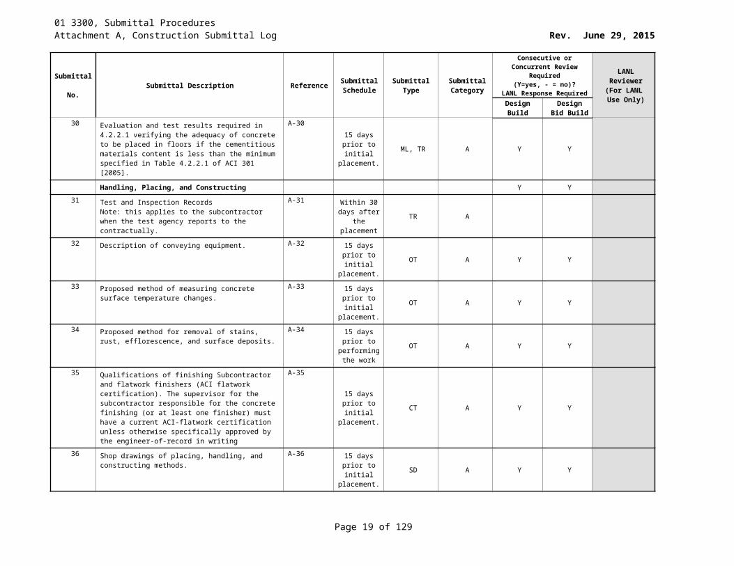
30 Evaluation and test results required in 4.2.2.1 verifying the adequacy of concrete to be placed in floors if the cementitious materials content is less than the minimum specified in Table 4.2.2.1 of ACI 301 [2005].
A-3015 days prior
to initial placement.
ML, TR A Y Y
Handling, Placing, and Constructing Y Y31 Test and Inspection Records
Note: this applies to the subcontractor when the test agency reports to the contractually.
A-31 Within 30 days after
the placement
TR A
32 Description of conveying equipment. A-32 15 days prior to initial
placement.OT A Y Y
33 Proposed method of measuring concrete surface temperature changes.
A-33 15 days prior to initial
placement.OT A Y Y
Page 12 of 83
01 3300, Submittal ProceduresAttachment A, Construction Submittal Log Rev. June 29, 2015
Submittal No. Submittal Description Reference Submittal
ScheduleSubmittal
TypeSubmittal Category
Consecutive or Concurrent Review Required (Y=yes, - = no)?
LANL Response Required
LANL Reviewer
(For LANL Use Only)Design
BuildDesign Bid
Build34 Proposed method for removal of stains, rust,
efflorescence, and surface deposits.A-34 15 days prior
to performing the work
OT A Y Y
35 Qualifications of finishing Subcontractor and flatwork finishers (ACI flatwork certification). The supervisor for the subcontractor responsible for the concrete finishing (or at least one finisher) must have a current ACI-flatwork certification unless otherwise specifically approved by the engineer-of-record in writing
A-35
15 days prior to initial
placement.CT A Y Y
36 Shop drawings of placing, handling, and constructing methods.
A-36 15 days prior to initial
placement.SD A Y Y
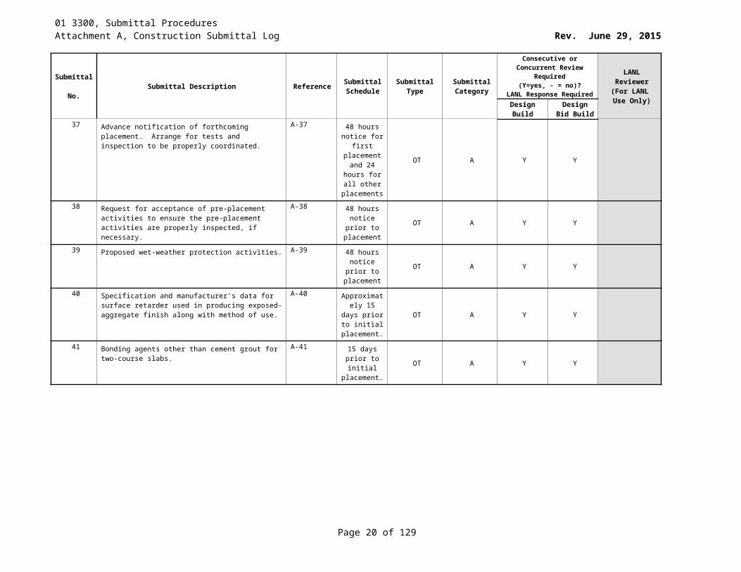
37 Advance notification of forthcoming placement. Arrange for tests and inspection to be properly coordinated.
A-37 48 hours notice for first
placement and 24 hours for all other placements
OT A Y Y
38 Request for acceptance of pre-placement activities to ensure the pre-placement activities are properly inspected, if necessary.
A-38 48 hours notice prior
to placementOT A Y Y
39 Proposed wet-weather protection activities. A-39 48 hours notice prior
to placementOT A Y Y
40 Specification and manufacturer’s data for surface retarder used in producing exposed-aggregate finish along with method of use.
A-40 Approximately 15 days
prior to initial placement.
OT A Y Y
41 Bonding agents other than cement grout for two-course slabs.
A-41 15 days prior to initial
placement.OT A Y Y
Page 13 of 83
01 3300, Submittal ProceduresAttachment A, Construction Submittal Log Rev. June 29, 2015
Submittal No. Submittal Description Reference Submittal
ScheduleSubmittal
TypeSubmittal Category
Consecutive or Concurrent Review Required (Y=yes, - = no)?
LANL Response Required
LANL Reviewer
(For LANL Use Only)Design
BuildDesign Bid
Build42 Batch Tickets
1. One legible copy of the batch ticket for each load of concrete to LANL’s STR
2. Provide batch tickets in accordance with: a. Name of ready-mix batch plantb. Serial number of ticketc. Dated. Truck Numbere. Name of purchaserf. Specific designation of job (name and location)g. Specific class or designation (pre-approved
design mix number) of the concrete in conformance with that employed in job specifications
h. Amount of concrete in cubic yardsi. Time loaded or of first mixing of cement and
aggregates.j. Water added by receiver of concrete and his
initials.k. Reading of revolution counter at the first addition
of water. l. Type and brand, and amount of cementm. Type and brand, and amount of admixturesn. Class, brand, and amount of coal fly ash, raw or
calcined natural pozzolans [grade, brand and amount of ground granulated blast-furnace slag].(Not required for LANS pre-approved
o. Information necessary to calculate the total mixing water. Total mixing water includes free water on the aggregates, water, and ice batched at the plant, and water added by the truck operator from the mixer tank (must be witnessed by LANL representative).
p. Maximum size of aggregateq. Weights of fine and coarse aggregater. Ingredients certified as being previously approved.s. Water/cement ratiot. Amount of water that can be added at the jobsite
without exceeding the water/cement ratio
A-42
At the completion of
each day’s concrete
placement(s)-
At the completition of each days
concrete placement(s)- Submittal
time to LANS shall be set
by the LANS STR
P A Y Y
Page 14 of 83
01 3300, Submittal ProceduresAttachment A, Construction Submittal Log Rev. June 29, 2015
Submittal No. Submittal Description Reference Submittal
ScheduleSubmittal
TypeSubmittal Category
Consecutive or Concurrent Review Required (Y=yes, - = no)?
LANL Response Required
LANL Reviewer
(For LANL Use Only)Design
BuildDesign Bid
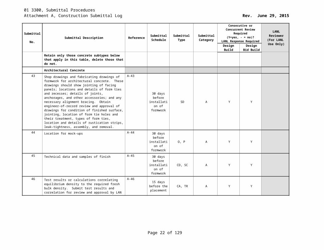
BuildRetain only those concrete subtypes below that apply in this table, delete those that do not.
Architectural Concrete43 Shop drawings and fabricating drawings of formwork for
architectural concrete. These drawings should show jointing of facing panels; locations and details of form ties and recesses; details of joints, anchorages, and other accessories; and any necessary alignment bracing. Obtain engineer-of-record review and approval of drawings for condition of finished surface, jointing, location of form tie holes and their treatment, types of form ties, location and details of rustication strips, leak-tightness, assembly, and removal.
A-43
30 days before
installation of formwork
SD A Y Y
44 Location for mock-ups A-44 30 days before
installation of formwork
O, P A Y Y
45 Technical data and samples of finish A-45 30 days before
installation of formwork
CD, SC A Y Y
46 Test results or calculations correlating equilibrium density to the required fresh bulk density. Submit test results and correlation for review and approval by LAN
A-46 15 days before the placement
CA, TR A Y Y
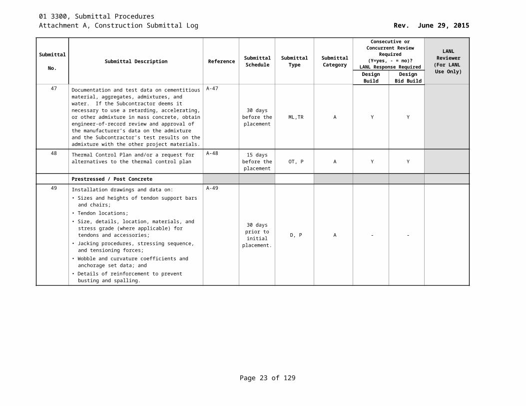
47 Documentation and test data on cementitious material, aggregates, admixtures, and water. If the Subcontractor deems it necessary to use a retarding, accelerating, or other admixture in mass concrete, obtain engineer-of-record review and approval of the manufacturer’s data on the admixture and the Subcontractor’s test results on the admixture with the other project materials.
A-47
30 days before the placement
ML,TR A Y Y
48 Thermal Control Plan and/or a request for alternatives to the thermal control plan
A-48 15 days before the placement
OT, P A Y Y
Page 15 of 83

01 3300, Submittal ProceduresAttachment A, Construction Submittal Log Rev. June 29, 2015
Submittal No. Submittal Description Reference Submittal
ScheduleSubmittal
TypeSubmittal Category
Consecutive or Concurrent Review Required (Y=yes, - = no)?
LANL Response Required
LANL Reviewer
(For LANL Use Only)Design
BuildDesign Bid
BuildPrestressed / Post Concrete
49 Installation drawings and data on:• Sizes and heights of tendon support bars and chairs;• Tendon locations;• Size, details, location, materials, and stress grade
(where applicable) for tendons and accessories;• Jacking procedures, stressing sequence, and tensioning
forces;• Wobble and curvature coefficients and anchorage set
data; and• Details of reinforcement to prevent busting and spalling.
A-49
30 days prior to initial
placement.D, P A - -
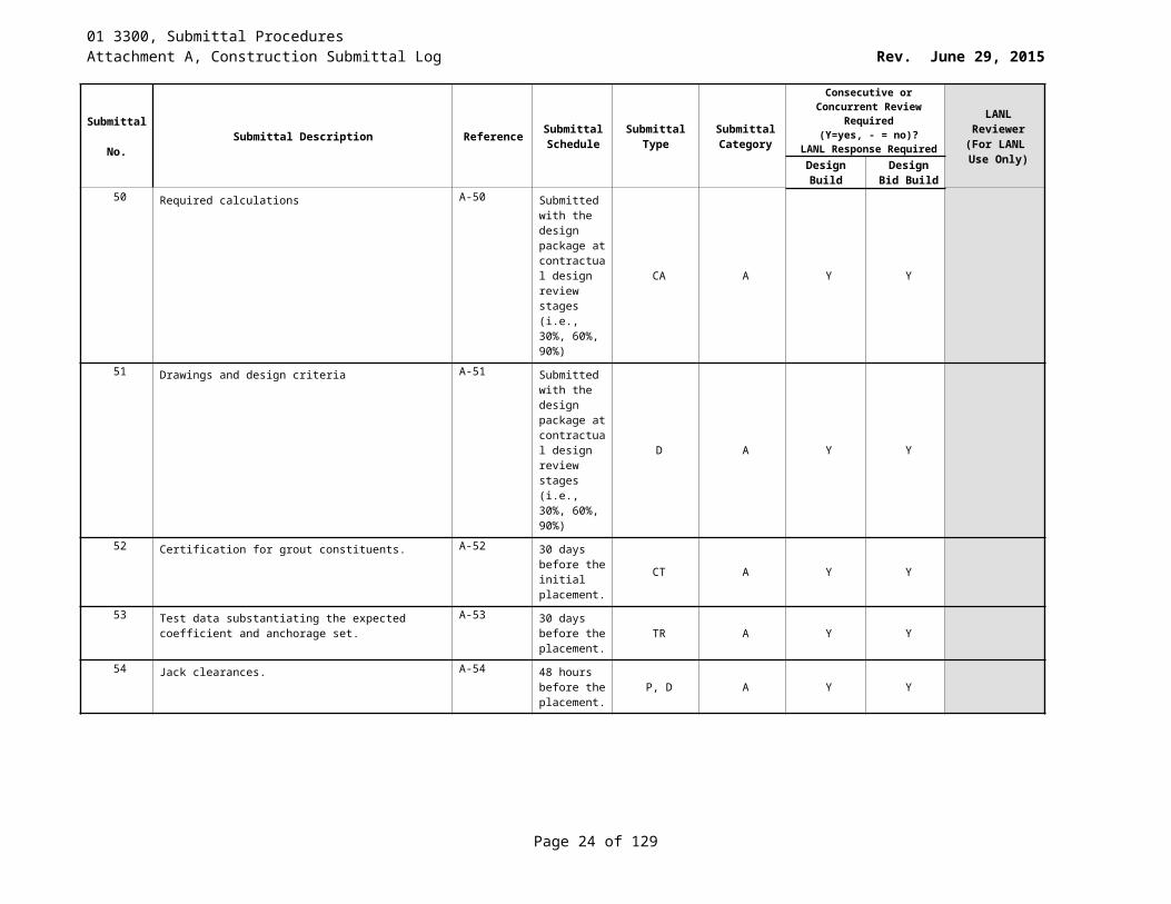
50 Required calculations A-50 Submitted with the design package at contractual design review stages (i.e., 30%, 60%, 90%)
CA A Y Y
51 Drawings and design criteria A-51 Submitted with the design package at contractual design review stages (i.e., 30%, 60%, 90%)
D A Y Y
52 Certification for grout constituents. A-52 30 days before the initial placement.
CT A Y Y
53 Test data substantiating the expected coefficient and anchorage set.
A-53 30 days before the placement.
TR A Y Y
54 Jack clearances. A-54 48 hours before the placement.
P, D A Y Y
Page 16 of 83
01 3300, Submittal ProceduresAttachment A, Construction Submittal Log Rev. June 29, 2015
Submittal No. Submittal Description Reference Submittal
ScheduleSubmittal
TypeSubmittal Category
Consecutive or Concurrent Review Required (Y=yes, - = no)?
LANL Response Required
LANL Reviewer
(For LANL Use Only)Design
BuildDesign Bid
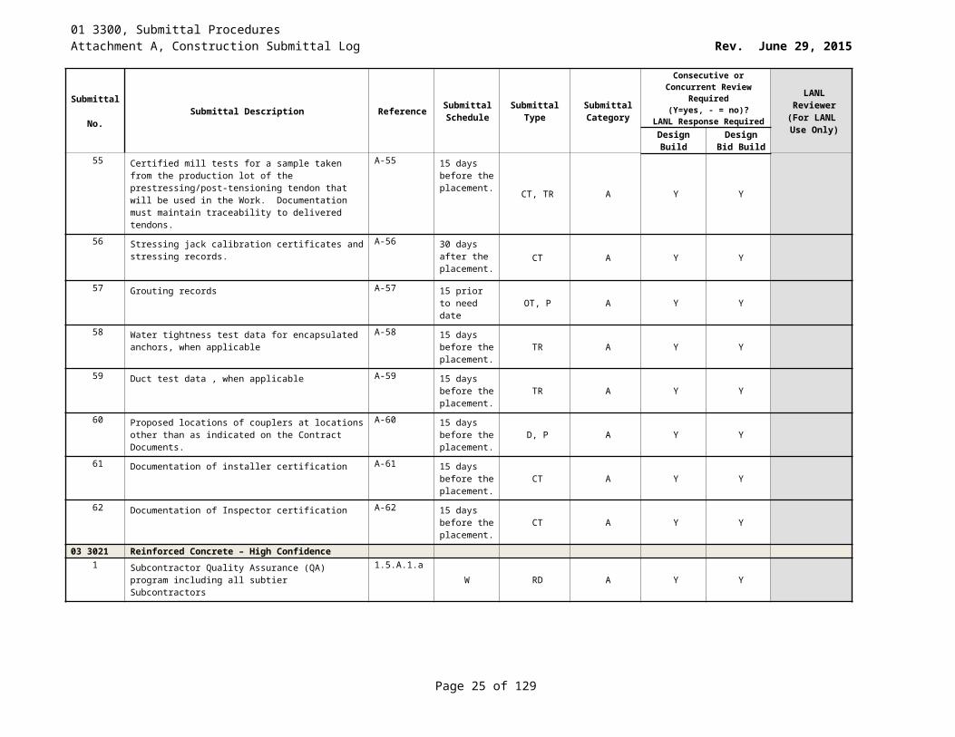
Build55 Certified mill tests for a sample taken from the production
lot of the prestressing/post-tensioning tendon that will be used in the Work. Documentation must maintain traceability to delivered tendons.
A-55 15 days before the placement. CT, TR A Y Y
56 Stressing jack calibration certificates and stressing records.
A-56 30 days after the placement.
CT A Y Y
57 Grouting records A-57 15 prior to need date OT, P A Y Y
58 Water tightness test data for encapsulated anchors, when applicable
A-58 15 days before the placement.
TR A Y Y
59 Duct test data , when applicable A-59 15 days before the placement.
TR A Y Y
60 Proposed locations of couplers at locations other than as indicated on the Contract Documents.
A-60 15 days before the placement.
D, P A Y Y
61 Documentation of installer certification A-61 15 days before the placement.
CT A Y Y
62 Documentation of Inspector certification A-62 15 days before the placement.
CT A Y Y
03 3021 Reinforced Concrete – High Confidence1 Subcontractor Quality Assurance (QA) program including
all subtier Subcontractors1.5.A.1.a
W RD A Y Y
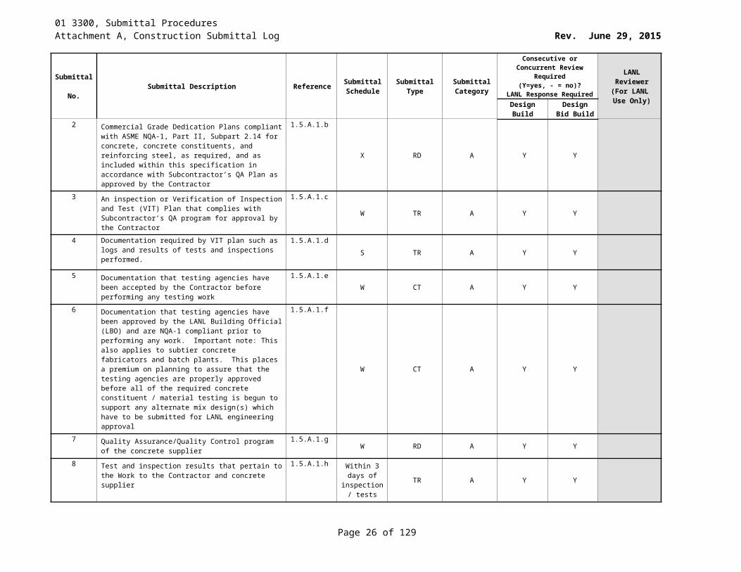
2 Commercial Grade Dedication Plans compliant with ASME NQA-1, Part II, Subpart 2.14 for concrete, concrete constituents, and reinforcing steel, as required, and as included within this specification in accordance with Subcontractor’s QA Plan as approved by the Contractor
1.5.A.1.b
X RD A Y Y
3 An inspection or Verification of Inspection and Test (VIT) Plan that complies with Subcontractor’s QA program for approval by the Contractor
1.5.A.1.cW TR A Y Y
4 Documentation required by VIT plan such as logs and results of tests and inspections performed.
1.5.A.1.dS TR A Y Y
5 Documentation that testing agencies have been accepted by the Contractor before performing any testing work
1.5.A.1.eW CT A Y Y
Page 17 of 83
01 3300, Submittal ProceduresAttachment A, Construction Submittal Log Rev. June 29, 2015
Submittal No. Submittal Description Reference Submittal
ScheduleSubmittal
TypeSubmittal Category
Consecutive or Concurrent Review Required (Y=yes, - = no)?
LANL Response Required
LANL Reviewer
(For LANL Use Only)Design
BuildDesign Bid
Build6 Documentation that testing agencies have been approved
by the LANL Building Official (LBO) and are NQA-1 compliant prior to performing any work. Important note: This also applies to subtier concrete fabricators and batch plants. This places a premium on planning to assure that the testing agencies are properly approved before all of the required concrete constituent / material testing is begun to support any alternate mix design(s) which have to be submitted for LANL engineering approval
1.5.A.1.f
W CT A Y Y
7 Quality Assurance/Quality Control program of the concrete supplier
1.5.A.1.gW RD A Y Y
8 Test and inspection results that pertain to the Work to the Contractor and concrete supplier
1.5.A.1.h Within 3 days of inspection/
testsTR A Y Y
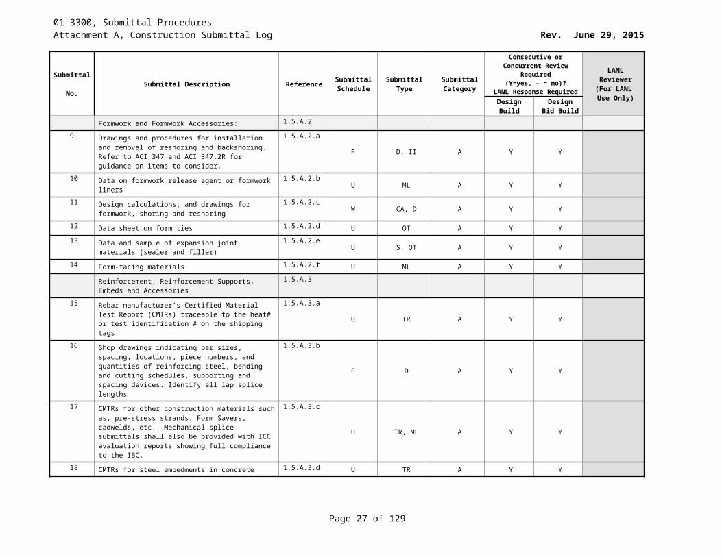
Formwork and Formwork Accessories: 1.5.A.2
9 Drawings and procedures for installation and removal of reshoring and backshoring. Refer to ACI 347 and ACI 347.2R for guidance on items to consider.
1.5.A.2.aF D, II A Y Y
10 Data on formwork release agent or formwork liners 1.5.A.2.b U ML A Y Y11 Design calculations, and drawings for formwork, shoring
and reshoring1.5.A.2.c
W CA, D A Y Y
12 Data sheet on form ties 1.5.A.2.d U OT A Y Y
13 Data and sample of expansion joint materials (sealer and filler)
1.5.A.2.eU S, OT A Y Y
14 Form-facing materials 1.5.A.2.f U ML A Y Y
Reinforcement, Reinforcement Supports, Embeds and Accessories
1.5.A.3
15 Rebar manufacturer’s Certified Material Test Report (CMTRs) traceable to the heat# or test identification # on the shipping tags.
1.5.A.3.aU TR A Y Y
16 Shop drawings indicating bar sizes, spacing, locations, piece numbers, and quantities of reinforcing steel, bending and cutting schedules, supporting and spacing devices. Identify all lap splice lengths
1.5.A.3.b
F D A Y Y
17 CMTRs for other construction materials such as, pre-stress strands, Form Savers, cadwelds, etc. Mechanical splice submittals shall also be provided with ICC evaluation reports showing full compliance to the IBC.
1.5.A.3.c
U TR, ML A Y Y
18 CMTRs for steel embedments in concrete 1.5.A.3.d U TR A Y Y
Page 18 of 83
01 3300, Submittal ProceduresAttachment A, Construction Submittal Log Rev. June 29, 2015
Submittal No. Submittal Description Reference Submittal
ScheduleSubmittal
TypeSubmittal Category
Consecutive or Concurrent Review Required (Y=yes, - = no)?
LANL Response Required
LANL Reviewer
(For LANL Use Only)Design
BuildDesign Bid
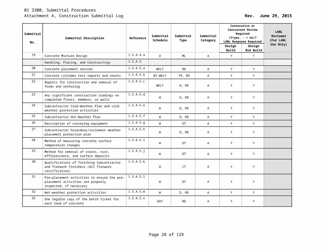
Build19 Concrete Mixture Design 1.5.A.4.a U ML A Y Y
Handling, Placing, and Constructing: 1.5.A.5
20 Concrete placement records 1.5.A.5.a WKLY RD A Y Y21 Concrete cylinder test reports and charts 1.5.A.5.b BI-WKLY TR, RD A Y Y
22 Reports for construction and removal of forms and reshoring
1.5.A.5.cWKLY O, RD A Y Y
23 Any significant construction loadings on completed floors, members, or walls
1.5.A.5.dW O, RD A Y Y
24 Subcontractor Cold-Weather Plan and cold-weather protection activities
1.5.A.5.eW O, RD A Y Y
25 Subcontractor Hot-Weather Plan 1.5.A.5.f W O, RD A Y Y
26 Description of conveying equipment 1.5.A.5.g W OT A Y Y27 Subcontractor hazardous/inclement weather placement
protection plan1.5.A.5.h
W O, RD A Y Y
28 Method of measuring concrete surface temperature changes
1.5.A.5.iW OT A Y Y
29 Method for removal of stains, rust, efflorescence, and surface deposits
1.5.A.5.jW OT A Y Y
30 Qualifications of finishing Subcontractor and flatwork finishers (ACI flatwork certification)
1.5.A.5.kW CT A Y Y
31 Pre-placement activities to ensure the pre-placement activities are properly inspected, if necessary
1.5.A.5.lW OT A Y Y
32 Wet-weather protection activities 1.5.A.5.m W O, RD A Y Y
33 One legible copy of the batch ticket for each load of concrete
1.5.A.5.nDAY RD A Y Y
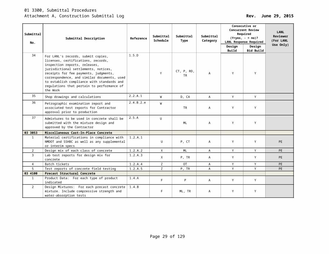
34 For LANL's records, submit copies, licenses, certifications, records, inspection reports, releases, jurisdictional settlements, notices, receipts for fee payments, judgments, correspondence, and similar documents, used to establish compliance with standards and regulations that pertain to performance of the Work
1.5.D
Y CT, P, RD, TR A Y Y
35 Shop drawings and calculations 2.2.A.1 W D, CA A Y Y36 Petrographic examination report and associated test
reports for Contractor approval prior to production2.4.B.2.e W TR A Y Y
37 Admixtures to be used in concrete shall be submitted with the mixture design and approved by the Contractor
2.5.A U ML A Y Y
Page 19 of 83
01 3300, Submittal ProceduresAttachment A, Construction Submittal Log Rev. June 29, 2015
Submittal No. Submittal Description Reference Submittal
ScheduleSubmittal
TypeSubmittal Category
Consecutive or Concurrent Review Required (Y=yes, - = no)?
LANL Response Required
LANL Reviewer
(For LANL Use Only)Design
BuildDesign Bid
Build03 3053 Miscellaneous Cast-In-Place Concrete
1 Material certifications in compliance with NMDOT and SSHBC as well as any supplemental or interim specs
1.2.A.1 U P, CT A Y Y PE
2 Design mix of each class of concrete 1.2.A.2 X ML A Y Y PE3 Lab test reports for design mix for concrete 1.2.A.3 X P, TR A Y Y PE4 Batch tickets 1.2.A.4 Z OT A Y Y PE5 Test reports of concrete field testing 1.2.A.5 Z P, TR A Y Y PE
03 4100 Precast Structural Concrete1 Product Data: For each type of product indicated 1.4.A F P A Y Y2 Design Mixtures: For each precast concrete mixture.
Include compressive strength and water-absorption tests1.4.B F ML, TR A Y Y
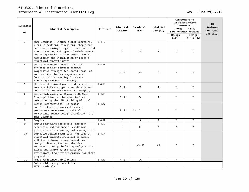
3 Shop Drawings: Include member locations, plans, elevations, dimensions, shapes and sections, openings, support conditions, and size, location, and types of reinforcement, including special reinforcement. Detail fabrication and installation of precast structural concrete units
1.4.C
F SD A Y Y
4 [For prestressed precast structural concrete provide required minimum compressive strength for stated stages of construction. Include magnitude and location of prestressing forces and stressing sequence of tendons]
1.4.D
F, Z SD A Y Y
5 [For post-tensioned precast structural concrete indicate type, size, details and location of post-tensioning anchorages.]
1.4.EF, Z SD A Y Y
6 Design Calculations: [Submit with Shop Drawings] [Need not be submitted] as determined by the LANL Building Official
1.4.FF, Z CA A Y Y
7 Design Modifications: If design modifications are proposed to meet performance requirements and field conditions, submit design calculations and Shop Drawings
1.4.GF, Z CA, D A Y Y
8 Samples 1.4.H F S A Y Y9 Provide handling procedures, erection sequences, and for
special conditions provide temporary bracing and shoring plan
1.4.IS II A Y Y
10 Delegated Design Submittal: For precast structural concrete indicated to comply with the performance requirements and design criteria, the comprehensive engineering design including analysis data, signed and sealed by the qualified Professional Engineer responsible for their preparation
1.4.J
F CA, D DD Y Y
11 [Fire Resistance Calculations] 1.4.K F, Z CA A Y YSustainable Design SubmittalsLEED Submittals:
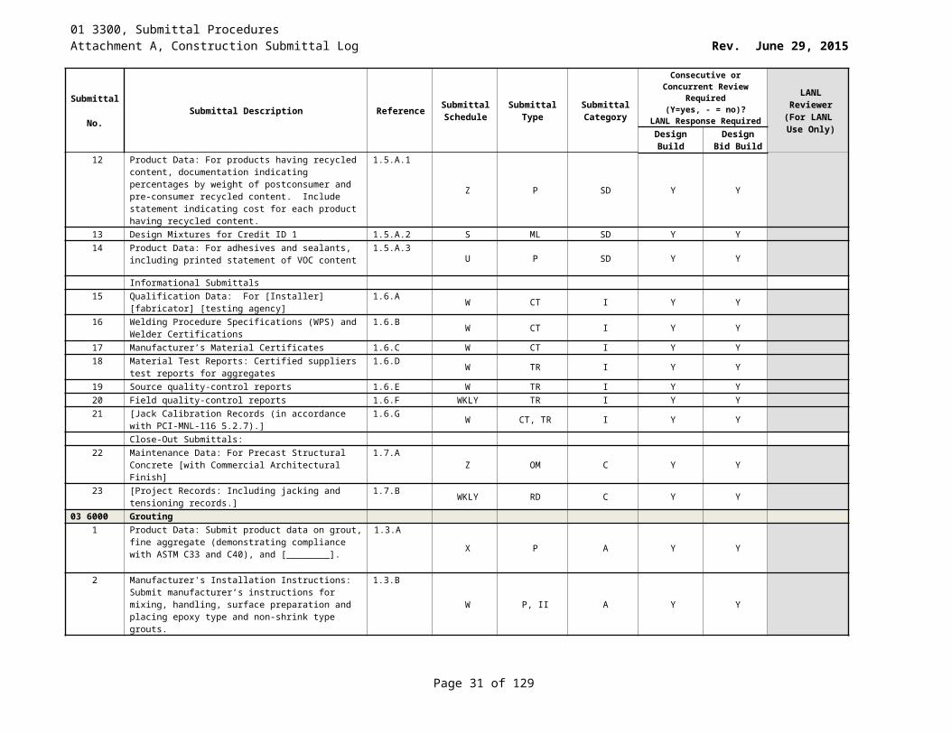
12 Product Data: For products having recycled content, documentation indicating percentages by weight of postconsumer and pre-consumer recycled content. Include statement indicating cost for each product having recycled content.
1.5.A.1
Z P SD Y Y
Page 20 of 83

01 3300, Submittal ProceduresAttachment A, Construction Submittal Log Rev. June 29, 2015
Submittal No. Submittal Description Reference Submittal
ScheduleSubmittal
TypeSubmittal Category
Consecutive or Concurrent Review Required (Y=yes, - = no)?
LANL Response Required
LANL Reviewer
(For LANL Use Only)Design
BuildDesign Bid
Build13 Design Mixtures for Credit ID 1 1.5.A.2 S ML SD Y Y14 Product Data: For adhesives and sealants, including
printed statement of VOC content1.5.A.3
U P SD Y Y
Informational Submittals15 Qualification Data: For [Installer] [fabricator] [testing
agency]1.6.A W CT I Y Y
16 Welding Procedure Specifications (WPS) and Welder Certifications
1.6.B W CT I Y Y
17 Manufacturer’s Material Certificates 1.6.C W CT I Y Y18 Material Test Reports: Certified suppliers test reports for
aggregates1.6.D W TR I Y Y
19 Source quality-control reports 1.6.E W TR I Y Y20 Field quality-control reports 1.6.F WKLY TR I Y Y21 [Jack Calibration Records (in accordance with PCI-MNL-
116 5.2.7).]1.6.G W CT, TR I Y Y
Close-Out Submittals:22 Maintenance Data: For Precast Structural Concrete [with
Commercial Architectural Finish]1.7.A Z OM C Y Y
23 [Project Records: Including jacking and tensioning records.]
1.7.B WKLY RD C Y Y
03 6000 Grouting1 Product Data: Submit product data on grout, fine
aggregate (demonstrating compliance with ASTM C33 and C40), and [________].
1.3.A
X P A Y Y
2 Manufacturer's Installation Instructions: Submit manufacturer’s instructions for mixing, handling, surface preparation and placing epoxy type and non-shrink type grouts.
1.3.B
W P, II A Y Y
3 Manufacturer's Certificates of Compliance: Certify [non-shrink cementitious grout] and [Insert Other Products Here] meet or exceed [ASTM C 1107] and [Insert Other Specified Requirements Here].
1.3.C
W P, CT A Y Y
4 Manufacturer's Certificate: Certify products meet or exceed specified sustainable design requirements related to recycled content and point of origin of materials
1.4.AW P, CT SD Y Y
04 2220 Reinforced Unit Masonry1 Shop drawings 1.4.B W SD A Y Y2 Product data 1.4.C W P A Y Y3 Manufacturer’s certificate 1.4.D W P, CT A Y Y
05 0520 Post-Installed Concrete and Grouted-Masonry Anchors – Normal Confidence
1 ICC-ES evaluation report (ESR) 1.5.A.1 Z CD A Y Y PE2 Technical documentation of the product 1.5.A.2 X CD A Y Y PE
Page 21 of 83
01 3300, Submittal ProceduresAttachment A, Construction Submittal Log Rev. June 29, 2015
Submittal No. Submittal Description Reference Submittal
ScheduleSubmittal
TypeSubmittal Category
Consecutive or Concurrent Review Required (Y=yes, - = no)?
LANL Response Required
LANL Reviewer
(For LANL Use Only)Design
BuildDesign Bid
Build3 For chemical anchors, information on adhesives 1.5.A.3 X CD A Y Y PE4 For chemical anchors, threaded rod or deformed
reinforcing bar information1.5.A.4 X CD A Y Y PE
5 Shipping, handling, and packaging procedures 1.5.A.5 X CD A Y Y6 Cleaning and coating documentation 1.5.A.6 X CD A Y Y7 Quality Assurance program 1.5.A.7 W OT A Y Y8 Certificates of compliance certifying the anchors meet
requirements of specification.1.5.A.8 Z CT A Y Y PE
05 0521 Post Installed Concrete Anchors -- High Confidence1 Inspection Plan 1.4.A.1 W OT A Y Y2 Quality Assurance Program 1.4.A.2 W OT A Y Y3 Material Test Reports 1.4.A.3 W P, TR A Y Y4 Qualification Test Reports and Data 1.4.A.4 W P, TR A Y Y5 Technical Documentation of the Product 1.4.A.5 W P A Y Y6 Recommended k coefficient 1.4.A.6 W P, CA A Y Y7 Values for the anchor pullout strength in tension 1.4.A.7 X P, CA A Y Y8 Shipping, handling, and packaging procedures 1.4.A.8 W P A Y Y9 Anchor marking plan 1.4.A.9 W P A Y Y10 Qualification testing plan and schedule 1.4.A.10 W P A Y Y11 Confirmatory testing pan and schedule 1.4.A.11 W P A Y Y12 Critical characteristics affecting the identification and
performance of the anchor being evaluated1.4.A.12 X P A Y Y
13 Anchor installer training documentation 1.4.B.1 W CT A Y Y14 Installation inspection record 1.4.B.2 Y TR A Y Y15 Test Inspection Record 1.4.B.3 Y TR A Y Y16 Failed anchor documentation 1.4.B.4 Z TR A Y Y
05 1000 Structural Metal FramingAction Submittals:
1 Product Data: For each type of product. 1.6.A W P A Y Y2 Shop Drawings: 1.6.B W SD A Y Y3 Include details of cuts, connections, splices, camber,
holes, and other pertinent data1.6.B.1 W D A Y Y
4 Embedment Drawings. 1.6.B.2 W D A Y Y5 Welds by standard AWS symbols, distinguishing between
shop and field welds, and show size, length, and type of each weld. Show backing bars that are to be removed and supplemental fillet welds where backing bars are to remain
1.6.B.3
W D A Y Y
6 Indicate type, size, and length of bolts, distinguishing between shop and field bolts. Identify pretensioned and slip-critical, high-strength bolted connections.
1.6.B.4W D A Y Y
7 Identify members and connections of the Seismic-Load-Resisting System.
1.6.B.5 W D A Y Y
8 Indicate locations and dimensions of protected zones 1.6.B.6 W D A Y Y9 Identify demand critical welds. 1.6.B.7 W D A Y Y
Page 22 of 83
01 3300, Submittal ProceduresAttachment A, Construction Submittal Log Rev. June 29, 2015
Submittal No. Submittal Description Reference Submittal
ScheduleSubmittal
TypeSubmittal Category
Consecutive or Concurrent Review Required (Y=yes, - = no)?
LANL Response Required
LANL Reviewer
(For LANL Use Only)Design
BuildDesign Bid
Build10 Welding Procedure Specification (WPS) and Procedure
Qualification Record (PQR)1.6.C W D A Y Y
11 Delegated Design Submittal: For structural-steel connections indicated to comply with design loads, include analysis data signed and sealed by the professional engineer, registered in the State of New Mexico, responsible for their preparation.
1.6.D
F SD, CA DD Y Y
Informational Submittals: Y Y12 Qualification Data: For [Installer] [fabricator] [shop-
painting applicators] [professional engineer] [testing agency]
1.7.A
F CT I Y Y
13 Welder Performance Qualification Records (WPQR) 1.7.B F CT I Y Y14 Paint Compatibility Certificates: From manufacturers of
topcoats applied over shop primers, certifying that shop primers are compatible with topcoats.
1.7.C
W P I Y Y
15 Certified material test reports for structural steel, structural fasteners, and weld filler material, including chemical and physical properties.
1.7.DS TR I Y Y
16 Product Test Reports 1.7.E F TR I Y Y17 Survey of existing conditions 1.7.F F P I Y Y18 Source quality-control reports 1.7.G F P I Y Y19 Field quality-control reports 1.7.H WKLY P I Y Y
Sustainable Design Submittals: Y Y20 Product Data: For products having recycled content,
documentation indicating percentages by weight of postconsumer and pre-consumer recycled content. Include statement indicating cost for each product having recycled content.
1.8.A
W P SD Y Y
21 Laboratory Test Reports for Credit IEQ 4.2: For primers, documentation indicating that products comply with the testing and product requirements of the California Department of Public Health's (formerly, the California Department of Health Services') "Standard Method for the Testing and Evaluation of Volatile Organic Chemical Emissions from Indoor Sources Using Environmental Chambers."
1.8.B
W P, TR SD Y Y
05 1305 Stainless Steel1 Certified Material Test Reports (CMTR) 1.4.A.1 W P, TR A Y Y2 Material Safety Data Sheets (MSDS) 1.4.A.2 W P A Y Y
05 2100 Steel Joist Framing1 Shop drawings: Steel joints 1.3.A.1 F SD A Y Y2 Certificates: Accessories 1.3.A.2.a W P, CT A Y Y3 Certificates: Welder qualification 1.3.A.2.b Z P, CT A Y Y4 Test Reports: Erection Inspection 1.3.A.3.a WKLY P, TR A Y Y5 Test Reports: Welding Inspections 1.3.A.3.b WKLY P, TR A Y Y
Page 23 of 83
01 3300, Submittal ProceduresAttachment A, Construction Submittal Log Rev. June 29, 2015
Submittal No. Submittal Description Reference Submittal
ScheduleSubmittal
TypeSubmittal Category
Consecutive or Concurrent Review Required (Y=yes, - = no)?
LANL Response Required
LANL Reviewer
(For LANL Use Only)Design
BuildDesign Bid
Build05 3000 Metal Decking
1 Product data: for each type of deck, accessory, and product indicated.
1.4.A W P A Y Y
2 Shop Drawings 1.4.B F SD A Y Y3 Welding Procedure Specifications (WPS) and Welder
Certifications1.5.A F CT, P I Y Y
4 Product Certificates: For each type of metal deck. 1.5.B F I Y Y5 Product Test Reports. 1.5.C F TR I Y Y6 ICC Evaluation Reports: For metal deck. 1.5.D F O I Y Y7 Field quality-control reports. 1.5.E WKLY P I Y Y8 Product Data: For products having recycled content,
documentation indicating percentages by weight of postconsumer and preconsumer recycled content. Include statement indicating cost for each product having recycled content
1.6.A
W P SD Y Y
9 Laboratory Test Reports: For primers, documentation indicating that products comply with the testing and product requirements for the California Department of Health Services, “Standard Practice for the Testing of Volatile Organic Emissions from Various Sources Using Small-Scale Environmental Chambers.”
1.6.B
W P, TR SD Y Y
05 4000 Cold-Formed Metal Framing1 Catalog data on standard framing members describing
materials, finish and including structural properties tables.1.3.A X P, CD A, I Y Y
2 Shop drawings: Indicate component details, [framed openings,] [bearing,] [anchorage,] [loading,] [welds,] [type and location of fasteners,] and accessories or items required of related Work
1.3.B.1
F SD A, I Y Y
3 Shop drawings: Indicate [stud,] [floor joist,] [ceiling joist,] [roof joist,] [roof rafter,] [roof truss,] [and] [________] layout
1.3.B.2F SD A, I Y Y
4 Shop drawings: Describe method for securing [studs] [________] to tracks and for [bolted] [welded] [________] framing connections
1.3.B.3F SD A, I Y Y
5 Installation instructions indicating special procedures, perimeter conditions requiring special attention.
1.3.C W P, II A, I Y Y
6 Mail Certifications: Submit mill certifications for steel delivered to site. Certify steel bare metal thickness in 0.001 inch, yield strength, tensile strength, total elongation in 2 inch or 8 inch gauge length, chemical analysis, and galvanized coating thickness.
1.3.D
W P, CT A, I Y Y
7 SUSTAINABLE DESIGN: Manufacturer’s Certificate: Certify products meet or exceed specified sustainable design requirements.
1.4.AX P, CT SD Y Y
Page 24 of 83
01 3300, Submittal ProceduresAttachment A, Construction Submittal Log Rev. June 29, 2015
Submittal No. Submittal Description Reference Submittal
ScheduleSubmittal
TypeSubmittal Category
Consecutive or Concurrent Review Required (Y=yes, - = no)?
LANL Response Required
LANL Reviewer
(For LANL Use Only)Design
BuildDesign Bid
Build8 SUSTAINABLE DESIGN:
Materials resource certificates:
1)Certify: source and origin for [salvaged] [and] [reused] products
2)Certify: recycled material content for recycled content products
3)Certify: source for local and regional materials and distance from Project site
1.4.A.1
X P, CT SD Y Y
9 SUSTAINABLE DESIGN:Indoor air quality certificates:Certify volatile organic compound content for each interior paint and coating
1.4.A.2
X P, CT SD Y Y
10 SUSTAINABLE DESIGN:Product Cost Data: cost of products to verify compliance with Project sustainable design requirements. Exclude cost of labor and equipment to install products
1.4.B
Y P SD Y Y
11 SUSTAINABLE DESIGN cost data for the following products:a. Salvaged productsb. Reused productsc. Products with recycled material contentd. Local and regional products
1.4.B.1
Y P SD Y Y
05 5000 Metal Fabrications1 Product data: for products used in metal fabrications,
including paint products, grout and fasteners.1.4.A W P, CD A, I Y Y
2 Shop drawing describing each fabricated item. Indicate profiles, sizes, connection attachments, reinforcing, anchorage, size type of fasteners, and accessories. Erection drawings, elevations, and details where applicable. Indicate welded connections using standard AWS welding symbols. Indicate net weld lengths
1.4.B
F D A, I Y Y
3 Samples: Submit two [________], [____x____] inch in size illustrating factory finishes [________].
1.4.C F S (2) A, I Y Y
4 Welders certifications 1.4.D F P, CT A, I Y Y5 Mill Certificate of compliance for Steel 1.4.E F P A, I Y Y6 Paint Compatibility Certificates: From manufacturers of
topcoats applied over shop primers certifying that shop primers are compatible with topcoats
1.4.FW P, CT A, I Y Y
7 Delegated-Design: For installed products indicated to comply with performance requirements and design criteria, including analysis data signed and sealed by the qualified professional engineer responsible for their preparation.
1.4.G
W P DD Y Y
8 Welding Procedures: written welding procedure specification (WPS) document per AWS Code requirements.
1.4.HF P A, I Y Y
Page 25 of 83
01 3300, Submittal ProceduresAttachment A, Construction Submittal Log Rev. June 29, 2015
Submittal No. Submittal Description Reference Submittal
ScheduleSubmittal
TypeSubmittal Category
Consecutive or Concurrent Review Required (Y=yes, - = no)?
LANL Response Required
LANL Reviewer
(For LANL Use Only)Design
BuildDesign Bid
Build9 Qualification For qualified professional engineer 1.4.I F P A, I Y Y10 Sustainable Design:
Product Data: Indicating percentages by weight of postconsumer and pre-consumer recycled content for products having recycled content. Include statement indicating costs for each product having recycled content.
1.5.A
X P SD Y Y
11 Sustainable Design:Shop Drawings: Manufacturer’s certificate: Certify products meet or exceed specified sustainable design requirements
1.5.B
X P, CT,SD SD Y Y
12 Sustainable Design:Materials resources certificates1)Certify: source and origin for [salvaged] [and] [reused] products2)Certify: recycled material content for recycled content products3)Certify: source for local and regional materials and distance from Project site
1.5.B.1
X P, CT SD Y Y
13 Sustainable Design:Indoor air quality certificates:Certify volatile organic compound content for each interior paint coating.
1.5.B.2
X P, CT SD Y Y
14 Sustainable Design:Product cost data: Cost of products to verify compliance with Project sustainable design requirements. Exclude cost of labor and equipment to install products
1.5.C
Y P SD Y Y
15 Sustainable Design:Cost data for the following products:a. Salvaged productsb. Reused productsc. Products with recycled material contentd. Local and regional products
1.5.C.1
Y P SD Y Y
05 5213 Pipe and Tube Railing1 Product Data
a. Manufacturer’s product line of mechanically connected railings
b. Railing bracketsc. Paint products
1.5.A.1
X P, CD A Y Y
2 Shop Drawings 1.5.A.2 F SD A Y Y3 Samples: Submit [two] [________], [________] inch long
samples of handrail. Submit [two] [________] samples, of [elbow] [Tee] [wall bracket] [escutcheon] [and] [end stop].
1.5.A.3F S A Y Y
4 Certificates: Paint Compatibility Certificates: From manufacturers of topcoats applied over shop primers certifying that shop primers are compatible with topcoats
1.5.A.4W P, CT A Y Y
5 Sustainable Design:Manufacturer’s Certificates
1.6.A X P, CT SD Y Y
Page 26 of 83
01 3300, Submittal ProceduresAttachment A, Construction Submittal Log Rev. June 29, 2015
Submittal No. Submittal Description Reference Submittal
ScheduleSubmittal
TypeSubmittal Category
Consecutive or Concurrent Review Required (Y=yes, - = no)?
LANL Response Required
LANL Reviewer
(For LANL Use Only)Design
BuildDesign Bid
Build6 Sustainable Design:
Materials Resources Certificates1.6.A.1 X P, CT SD Y Y
7 Sustainable Design:Indoor Air Quality Certificates
1.6.A.2 X P, CT SD Y Y
8 Sustainable Design:Product Cost Data: Cost of products to verify compliance with Project sustainable design requirements. Exclude cost of labor and equipment to install products
1.6.B
Y P SD Y Y
9 Sustainable Design:Cost data for the following products:a. Salvaged productsb. Reused productsc. Products with recycled material contentd. Local and regional products
1.6.B.1
Y P SD Y Y
05 5350 Gratings and Floor Plates1 Catalog data 1.3.A X P, CD A Y Y2 Shop Drawings: Indicate details of [gratings,] [plates,]
component supports, [anchorage,] [openings,] perimeter construction details, and tolerances. Indicate welded connections using standard AWS A2.4 welding symbols. Indicate net weld lengths
1.3.B
F SD A Y Y
3 Mill certificates: Signed by manufacturers of stainless-steel sheet certifying that products furnished comply with requirements
1.3.CF P, CT A Y Y
4 Paint compatibility Certificates: From manufacturers of topcoats applied over shop primers certifying that shop primers are compatible with topcoats
1.3.DW P, CT A Y Y
5 Delegated-Design: For installed products indicated to comply with performance requirements and design criteria, including analysis data signed and sealed by the qualified professional engineer responsible for their preparation
1.3.E
F P DD Y Y
6 Qualification Data: For qualified professional engineer 1.3.F F P A Y Y7 Manufacturers Installation Instructions: special
requirements of [opening,] [perimeter framing,] [and] [ _________ ].
1.3.GW P-II A Y Y
8 SUSTAINABLE DESIGN:Product Data: Indicating percentages by weight of postconsumer and preconsumer recycled content for products having recycled content. Include statement indicating costs for each product having recycled content.
1.4.A
X P, CD SD Y Y
9 SUSTAINABLE DESIGN:Manufacturer’s certificate: Certify products meet or exceed specified sustainable design requirements
1.4.BX P, CT SD Y Y
10 SUSTAINABLE DESIGN:Materials resources certificates
1.4.B.1 X P, CT SD Y Y
11 SUSTAINABLE DESIGN:Indoor air quality certificates
1.4.B.2 X P, CT SD Y Y
Page 27 of 83
01 3300, Submittal ProceduresAttachment A, Construction Submittal Log Rev. June 29, 2015
Submittal No. Submittal Description Reference Submittal
ScheduleSubmittal
TypeSubmittal Category
Consecutive or Concurrent Review Required (Y=yes, - = no)?
LANL Response Required
LANL Reviewer
(For LANL Use Only)Design
BuildDesign Bid
Build
06 1000 Rough Carpentry1 Product data 1.3.A X P A - -2 Fastener Patterns: full size templates for fasteners in
exposed framing1.3.B F SD A - -
3 Material certificates for dimension lumber 1.4.A F P, CT I - -4 Evaluation Reports from ICC-ES 1.4.B F CT I - -5 Chain-of-custody certificates 1.5.A Z CT, RD SD - -6 Product data for adhesives, documentation including
printed statement of VOC content1.5.B Z P, RD SD - -
7 Product data for composite wood products, documentation indicating that product contains no urea formaldehyde
1.5.CZ P, RD SD - -
8 Laboratory Test Reports 1.5.D Z TR SD - -9 Warranty Documentation: chemical treatment
manufacturer’s standard warranty1.6.A Z WA C - -
06 2000 Finish Carpentry1 Shop drawings of architectural woodwork 1.3.A.1 F SD A Y Y2 Catalog data for hardware and specialty items. 1.3.A.2 W P, CD A Y Y
06 4100 Architectural Wood Casework1 Shop drawings of architectural woodwork 1.3.A.1 F SD A Y Y2 Catalog data for hardware and specialty items. 1.3.A.2 W P, CD A Y Y
07 0150.19 Preparation for Re-Roofing1 Product Data: 1.5.A X P, CD A - -2 For each type of product indicated 1.5.A.1 X P, CD A - -3 Temporary Roofing: Include Product Data and description
of temporary roofing system. If temporary roof will remain in place, submit surface preparation requirements needed to receive permanent roof, and submit a letter from roofing membrane manufacturer stating acceptance of the temporary membrane and that its inclusion will not adversely affect the roofing system’s resistance to fire and wind [or its FM Global rating].
1.5.A.2
X P A - -
4 Field Reports 1.5.B WKLY P A - -5 Test and Evaluation Reports: Fastener pull-out test
report.1.5.B.1 Z P, TR A - -
6 Field Quality Control: Landfill records: Records: Indicate receipt and acceptance of hazardous wastes, such as asbestos-containing material, by a landfill facility licensed to accept hazardous wastes.
1.5.C.1
WKLY R,D A - -
Page 28 of 83
01 3300, Submittal ProceduresAttachment A, Construction Submittal Log Rev. June 29, 2015
Submittal No. Submittal Description Reference Submittal
ScheduleSubmittal
TypeSubmittal Category
Consecutive or Concurrent Review Required (Y=yes, - = no)?
LANL Response Required
LANL Reviewer
(For LANL Use Only)Design
BuildDesign Bid
Build7 Special Procedure: Photographs and Videotape: Show
existing conditions of adjoining construction and site improvements, including exterior and interior finish surfaces that might be misconstrued as having been damaged by reroofing operations. LANL STR will obtain government approved camera and approved permission forms prior to taking of photographs or videotape.
1.5.D.1
W PH A - -
8 Qualification Statements: For installer [including certificate that Installer is licensed to perform asbestos abatement] [and] [is approved by warrantor of existing roofing system].
1.5.E.
W P, CT A - -
07 0155 Roof PatchingInstallation instructions 1.2.A.1 W P A - -
07 1113 Bituminous DampproofingProduct data 1.3.A.1 X P A - -Material Certificates 1.3.A.2 W P, CT A - -Manufacturer’s Installation Instructions 1.3.A.3 W II A - -Sustainable Design Submittals: Product Data 1.3.B.1 X P SD - -
07 1326 Self-Adhering Sheet Waterproofing1 Product Data 1.3.A.1 X P, CD A - -2 Shop Drawings 1.3.A.2 W D, SD A - -3 Product Test Reports 1.3.A.3 W P, TR A - -4 Manufacturer’s Installation Instructions 1.3.A.4 W II A - -5 Manufacturer’s Certificate 1.3.A.5 W P, CT A - -6 Special warranties 1.3.A.6 At closeout P, WA C - -7 Sustainable Design Submittals: Manufacturer’s Certificate 1.3.B.1 Z P, CT SD - -8 Materials resources certificates 1.3.B.1.a Z P, CT A - -9 Close Out Submittals – Warranty Documentation 1.2.C.1 At closeout P, WA C - -
07 2100 Thermal Insulation1 Product data 1.3.A X P, CD A - Y2 Certification 1.3.B W P, CT A - -3 Product Test Reports 1.3.C WKLY P, TR A - -4 Research/Evaluation Reports 1.3.D W P A - -5 Material Safety Data Sheets (MSDS): Submit MSDS for
each adhesive product.1.3.E W P A - -
6 SUSTAINABLE DESIGNProduct data indicating percentages by weight of postconsumer and pre-consumer recycled content for products having recycled content.
1.4.A
X P SD - -
7 Statement indicating costs for each product having recycled content.
1.4.A.1 X P A - -
07 2400 Exterior Insulation and Finish Systems1 Product data: Manufacturer’s technical data for each
component of exterior insulation and finish system1.6.A X P, CD A - -
2 Installation instructions: Manufacturer’s literature indicating installation specifications and procedures
1.6.B W P A - -
3 Shop drawings 1.6.C F SD A Y Y
Page 29 of 83
01 3300, Submittal ProceduresAttachment A, Construction Submittal Log Rev. June 29, 2015
Submittal No. Submittal Description Reference Submittal
ScheduleSubmittal
TypeSubmittal Category
Consecutive or Concurrent Review Required (Y=yes, - = no)?
LANL Response Required
LANL Reviewer
(For LANL Use Only)Design
BuildDesign Bid
Build4 Samples: 24-inch square panels for each type of finish-
coat color and texture indicated, prepared using same tools and techniques intended for actual work including [custom trim, each profile,] [and] [an aesthetic reveal]
1.6.D
Z S A - -
5 Qualification Data: For [Installer] [fabricator/erector] 1.7.A W P I Y Y6 Manufacturer Certificates: Signed by EIFS manufacturer
certifying the following:1. EIFS substrate is acceptable to EIFS manufacturer.2. Accessory products installed with EIFS, including [joint
sealants,] [flashing,] [water resistant barriers,] [trim,] <Insert accessory> whether or not furnished by EIFS manufacturer and whether or not specified in this section, are acceptable to EIFS manufacturer.
1.7.B
F CT I - -
7 Product Certificates: For cementitious materials and aggregates and for insulation
1.7.C F CT I - -
8 Product Test Reports: For each EIFS assembly and component, for tests performed by a qualified testing agency
1.7.DF TR I - -
9 Field quality-control reports [and special inspection reports]
1.7.E By LANL P I - -
10 Evaluation Reports: For EIFS, including insulation [fasteners,] [flexible membrane flashing,] from ICC-ES
1.7.F F P I - -
11 Sample Warranty: For manufacturer’s special warranty. 1.7.G F WA I - -12 Manufacturer’s Certificate: Certify products meet or
exceed specified sustainable design requirements.1.8.A F CT SD - -
13 Product Data: For solvent cements and adhesive primers, documentation including printed statement of VOC content
1.8.BF P SD - -
14 Laboratory Test Reports: For solvent cements and adhesive primers, documentation indicating that products comply with testing and product requirements of 40 CFR 59, Subpart D (EPA Method 24), National Volatile Organic Chemical Emission Standards for Architectural Coatings
1.8.C
F TR SD - -
15 Maintenance Data: Include maintenance data for EIFS in maintenance manuals
1.9.A B M, P C - -
16 Warranty: Executed copy of Manufacturer’s Special Warranty in accordance with Paragraph 1.15
1.9.B B WA C - -
17 Extra Materials: Furnish materials in accordance with Paragraph 1.16
1.9.C B ML C - -
07 4113 Metal Roof Panels1 Catalog data 1.4.A X P, CD A - -2 Shop drawings 1.4.B W D, SD A - -3 Samples 1.4.C X S A - -4 Manufacturer’s Certificates: Signed by manufacturer
certifying that roof panels comply with energy performance requirements specified in “Performance Requirements” Article.
1.4.D
X P, CT A - -
Page 30 of 83
01 3300, Submittal ProceduresAttachment A, Construction Submittal Log Rev. June 29, 2015
Submittal No. Submittal Description Reference Submittal
ScheduleSubmittal
TypeSubmittal Category
Consecutive or Concurrent Review Required (Y=yes, - = no)?
LANL Response Required
LANL Reviewer
(For LANL Use Only)Design
BuildDesign Bid
Build5 Evidence of meeting performance requirements. 1.4.D.1 W P A - -6 SUSTAINABLE DESIGN
Product Test Reports for roof panels, indicating that panels comply with solar reflectance index requirement.
1.5.AX P-TR SD - -
7 Product Data: indicating percentages by weight of postconsumer and preconsumer recycled content for products having recycled content.
1.5.BX P, CD A - -
8 Statement indicating costs for each product having recycled content.
1.5.B.1 X P A - -
9 Maintenance Data 1.6.A at closeout OM A - -10 Warranty 1.6.B at closeout WA A - -
07 5050 Membrane Roofing General Provisions1 Catalog Data 1.3.A.1 X S,CD A - -2 Installation instructions 1.3.A.3 W II A - -3 Retrofit shop drawings 1.3.A.4 F D A - -4 Warranty 1.3.A.5 at closeout WA A - -5 Water intrusion plan 1.3.A.6 Z OT A - -6 Qualifications 1.3.A.7 W OT, CT A - -
07.5213.13 Atatic-Polypropylene Modified-Bitumen Roofing, Cold-Applied
1 Product Data 1.4.A X P A - -2 Shop Drawings 1.4.B F SD A - -3 Selection Samples 1.4.C W SC
(2 for each) A - -
4 Verification Samples 1.4.D Y SC(2 for each) A - -
5 Manufacturers Certificates 1.4.E W P, CT A - -6 Product Test Reports 1.4.F X P, TR A - -7 Research/Evaluation Reports 1.4.G X P A - -8 Manufacturer’s Instructions 1.4.H W P, II A - -9 Qualification Data 1.4.I W P A - -
07 5216 Styrene-Butadiene-Styrene Modified Bituminous Membrane Roofing
1 Product Data 1.4.A X P A - -2 Preparation instructions and recommendations 1.4.A.1 W P A - -3 Storage and handling requirements and recommendations 1.4.A.2 S P A - -4 Roof insulation 1.4.A.3 X P A - -5 Manufacturer’s published specifications, base flashing
details for the specified system1.4.A.4 W P A - -
6 Material Safety Data sheets on all roofing materials to be used
1.4.A.5 W P A - -
7 Shop Drawings: 1.4.B8 Roof system and base flash configuration 1.4.B.1 W D A - -9 Penetration Details 1.4.B.2 W D A - -10 Termination Details 1.4.B.3 W D A - -11 Fastening patterns 1.4.B.4 W D A - -
Page 31 of 83
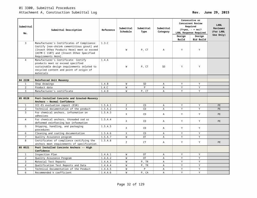
01 3300, Submittal ProceduresAttachment A, Construction Submittal Log Rev. June 29, 2015
Submittal No. Submittal Description Reference Submittal
ScheduleSubmittal
TypeSubmittal Category
Consecutive or Concurrent Review Required (Y=yes, - = no)?
LANL Response Required
LANL Reviewer
(For LANL Use Only)Design
BuildDesign Bid
Build12 Tapered insulation design 1.4.B.5 W D A - -13 Selection Samples 1.4.C X SC A - -14 Verification Samples 1.4.D X SC A - -15 Manufacturers Certificates: 1.4.E16 Evidence of complying with performance requirements 1.4.E.1 X P, CT A - -17 Product Test Reports 1.4.F X P, TR A - -18 Research/Evaluation Reports 1.4.G X P A - -19 Manufacturer’s Instructions:
published installation instructions and methods1.4.H.1 W P, II A - -
20 Qualification Data 1.4.I X P A - -21 Sustainable Design:
Product Test Reports for roof materials, indicating that roof materials comply with Solar Reflectance Index requirement
1.5.A
X TR SD - -
22 Sustainable Design:Product data for adhesives and sealants, including printed statement of VOC content
1.5.BX P SD - -
23 Sustainable Design:Submit Manufacturer’s documentation of Energy Star labeled roofing materials
1.5.CX P SD - -
24 Maintenance data: for roofing system, to include in roofing manuals
1.6.A at closeout P A - -
25 Roofing membrane Manufacturer’s warranty covering materials
1.6.B.1 at closeout P, WA A - -
26 Roofing Subcontractors Warranty covering workmanship 1.6.B.2 at closeout P, WA A - -07 5217 Styrene-Butadiene-Styrene Modified Bituminous
Membrane Roofing Cold-Applied1 Preparation instructions and recommendations 1.4.A.1 W P A - -2 Storage and handling requirements and recommendations 1.4.A.2 X P A - -3 Roof insulation product data sheets 1.4.A.3 X P A - -4 Manufacturer’s published specifications, base flashing
details for the specified system1.4.A.4 W P A - -
5 Material safety data sheets for all roofing materials to be used
1.4.A.5 W P A - -
6 Shop Drawings 1.4.B F SD A - -7 Roof system and base configuration 1.4.B.1 F D A - -8 Penetration details 1.4.B.2 F D A - -9 Termination details 1.4.B.3 F D A - -10 Fastening Patterns 1.4.B.4 F D A - -11 Tapered insulation design 1.4.B.5 F D A - -12 Selection Samples 1.4.C X SC (2) A - -13 Verification Samples 1.4.D X SC (2) A - -14 Manufacturers Certificates 1.4.E X P, CT A - -15 Evidence of complying with requirements 1.4.E.1 Y P A - -16 Product Test Reports 1.4.F X TR A - -17 Research/Evaluation Reports 1.4.G X P A - -
Page 32 of 83
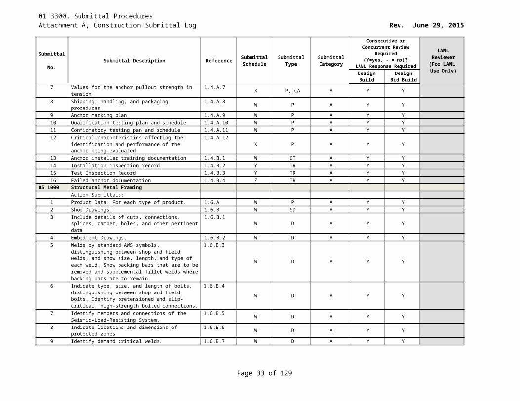
01 3300, Submittal ProceduresAttachment A, Construction Submittal Log Rev. June 29, 2015
Submittal No. Submittal Description Reference Submittal
ScheduleSubmittal
TypeSubmittal Category
Consecutive or Concurrent Review Required (Y=yes, - = no)?
LANL Response Required
LANL Reviewer
(For LANL Use Only)Design
BuildDesign Bid
Build18 Manufacturer’s Instructions 1.4.H W P, II A - -19 Qualification Data 1.4.I W P A - -20 Sustainable Design: Product Test Reports for roof
materials, indicating that roof materials comply with Solar Reflectance Index requirement
1.5.AX P, TR SD - -
21 Sustainable Design: Product data for adhesives and sealants, including printed statement of VOC content
1.5.B X P SD - -
22 Sustainable Design: Submit Manufacturer’s documentation of Energy Star labeled roofing materials
1.5.C X P SD - -
23 Maintenance data: for roofing system, to include in roofing manuals
1.6.A at closeout P, OM A - -
24 Roofing membrane Manufacturer’s warranty covering materials
1.6.B.1 at closeout P, WA A - -
25 Roofing Subcontractors Warranty covering workmanship 1.6.B.2 at closeout P, WA A - -07 5316 Chlorosulfonate-Polyethylene Roofing
Product Data: Manufacturer’s data sheets on each product to be used including:
1 Preparation instructions and recommendations. 1.4.A.1 X P A - -2 Storage and handling requirements and
recommendations.1.4.A.2 X P A - -
3 Roof insulation. 1.4.A.3 X P A - -4 Manufacturer’s published specifications, base flashing
details, for the specified system.1.4.A.4 F P A - -
5 Submit Material Safety Data Sheets on all roofing materials to be used.
1.4.A.5 U P A - -
Shop Drawings: - -6 Roof system and base flashing configuration. 1.4.B.1 F SD A - -7 Penetration details. 1.4.B.2 F SD A - -8 Termination details. 1.4.B.3 F SD A - -9 Fastening patterns. 1.4.B.4 F SD A - -10 Tapered insulation design. 1.4.B.5 F SD A - -11 Selection Samples: For each product specified, two
samples representing manufacturer’s full range of available colors and types
1.4.CX SC(2) A - -
12 Verification Samples: For each finish product specified, two samples representing actual product, color and finish
1.4.D X SC(2) A - -
13 Manufacturer’s Certificates. Submit evidence of complying with performance requirements.
1.4.E X CT A - -
14 Product Test Reports. 1.4.F X P, TR A - -15 Research/Evaluation reports 1.4.G X P A - -16 Manufacturer’s instructions: published installation
instructions and methods.1.4.H F P, II A - -
17 Qualification data: for qualified [installer] [manufacturer] [testing agency]
1.4.I W P, CD A - -
Sustainable Design Submittals: 1.518 Manufacturer’s Certificate: Certify products meet or
exceed specified sustainable design requirements.1.5.A F P, CT SD - -
Page 33 of 83
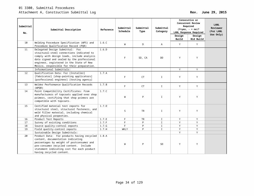
01 3300, Submittal ProceduresAttachment A, Construction Submittal Log Rev. June 29, 2015
Submittal No. Submittal Description Reference Submittal
ScheduleSubmittal
TypeSubmittal Category
Consecutive or Concurrent Review Required (Y=yes, - = no)?
LANL Response Required
LANL Reviewer
(For LANL Use Only)Design
BuildDesign Bid
Build19 Materials Resources Certificates: Certify recycled material
content for recycled content products.1.5.B.1 F P, CT SD - -
20 Materials Resources Certificates: Certify source for regional materials and distance from Project site.
1.5.B.2 F P, CT SD - -
21 Product Test Reports for roof materials, indicating that roof materials comply with Solar Reflectance Index requirement.
1.5.CF P, TR SD - -
22 Submit manufacturer’s documentation of Energy Star labeled roofing materials.
1.5.D F P SD - -
23 Product data for adhesives and sealants, including printed statement of VOC content.
1.5.E U P SD - -
24 Maintenance data: for roofing system to include in maintenance manuals.
1.6.A At closeout M C - -
25 Warranties: Submit a copy of the membrane manufacturer’s warranty covering materials.
1.6.B.1 At closeout WA C - -
26 Warranties: Submit copy of the Roofing Subcontractor’s warranty covering workmanship.
1.6.B.2 At closeout WA C - -
07 6200 Sheet Metal Flashing and Trim1 Catalog Data 1.3.A.1 X P, CD A - -2 Product Data 1.3.A X P A - -3 Shop Drawings: Include details for forming, joining,
supporting, and securing sheet metal flashing and trim, including pattern of seams, termination points, fixed points, expansion joints, expansion-joint covers, edge conditions, special conditions, and connections to adjoining work.
1.3.B.1
W D A - -
4 Samples for Initial Selection Purposes: Submit manufacturer’s color charts and texture variations for specified sheet materials to be exposed as finished surfaces
1.3.B.2
X SC A - -
5 Sustainable Design: Manufacturer’s Certificate 1.4.A X P, CT SD - -6 Sustainable Design: Material Resources Certificates:
Certify recycled material content for recycled content products
1.4.B.1X P, CT SD - -
7 Maintenance Data: For sheet metal flashing, trim and accessories to include in maintenance manuals
1.5.A at closeout P C - -
8 Sample of special warranty 1.5.B at closeout P, WA C - -07 7100 Roof Specialties
1 Product Data 1.3.A X P, ML A - -2 Shop drawings for roof accessories 1.3.B F SD A - -3 Coordination Drawings: roof plans 1.3.B.1 F SD A - -4 Samples 1.3.C X S A - -5 Manufacturer’s Installation instructions 1.3.D W P, II A - -6 Manufacturer’s Certificate 1.4.A W P, CT SD - -7 Materials Resources Certificates:
1. certify recycled material content for recycled content products.
1.4.BW P, CT SD - -
8 Operation and Maintenance Data 1.5.A At closeout P, OM C - -
Page 34 of 83
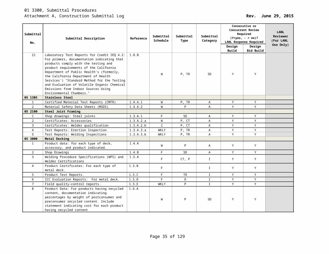
01 3300, Submittal ProceduresAttachment A, Construction Submittal Log Rev. June 29, 2015
Submittal No. Submittal Description Reference Submittal
ScheduleSubmittal
TypeSubmittal Category
Consecutive or Concurrent Review Required (Y=yes, - = no)?
LANL Response Required
LANL Reviewer
(For LANL Use Only)Design
BuildDesign Bid
Build9 Warranty 1.5.B Z P, WA C - -
07 7233 Roof Hatches1 Catalog data 1.3.A.1 X P, CD A - -2 Installation instructions 1.3.A.2 W P, II A - -3 Warranty 1.3.A.3 Z P, WA A - -
07 7600 Roof Pavers1 Catalog data 1.2.A.1 X P, CD A Y Y2 Installation instructions 1.2.A.2 W P, II A - -3 Samples 1.2.A.3 X (2)S A - -4 Warranty 1.2.A.4 Z P, WA A - -
07 8400 Firestopping1 Product data 1.4.A X P A Y Y2 Schedule 1.4.B W P, OT A Y Y3 Manufacturer’s Certificate 1.4.C W P A Y Y4 Engineering judgments 1.4.D W P, D A Y Y5 Manufacturer’s installation instructions 1.4.E W D A Y Y6 Qualification Data 1.5.A W CT I Y Y7 Product Test Reports 1.5.B X TR I Y Y8 Material Safety Data Sheets for each product supplied 1.5.C W ML I Y Y9 Materials Resources Certificates:
Certify recycled material content for recycled contents products.
Certify source for regional materials and distance from Project site.
1.6.A
At closeout CT SD Y -
10 Indoor Air Quality Certificates: Certify volatile organic compound content for
each interior [adhesive] [and] [sealant] and related primer
Certify firestopping products contain no added urea formaldehyde resins
1.6.B
At closeout CT SD Y -
11 Laboratory Test Reports 1.6.C At closeout TR SD Y -12 Complete maintenance material and detailed instructions
for repair/modifications for each product supplied1.7.A At closeout OM, SP C Y Y
13 Installer Certificates 1.7.B At closeout CT C Y Y07 9200 Joint Sealants
1 Product data 1.3.A X P, CD A - -2 Joint Sealant Schedule to include:
1. Joint sealant application, joint location, and designation.2. Joint sealant manufacturer and product name. 3. Joint sealant formulation. 4. Joint sealant color.
1.3.B
X P A - -
3 Samples for initial selection. 1.3.C X S, SC A - -4 Samples for verification 1.3.D X S, SC A - -5 Manufacturer’s Certifications 1.3.E X CT A - -6 Material Safety Data Sheets (MSDS) 1.3.F W P A - -7 Product test reports 1.3.G X P, TR A - -8 Manufacturer’s installation instructions 1.3.H W P, II A - -
Page 35 of 83
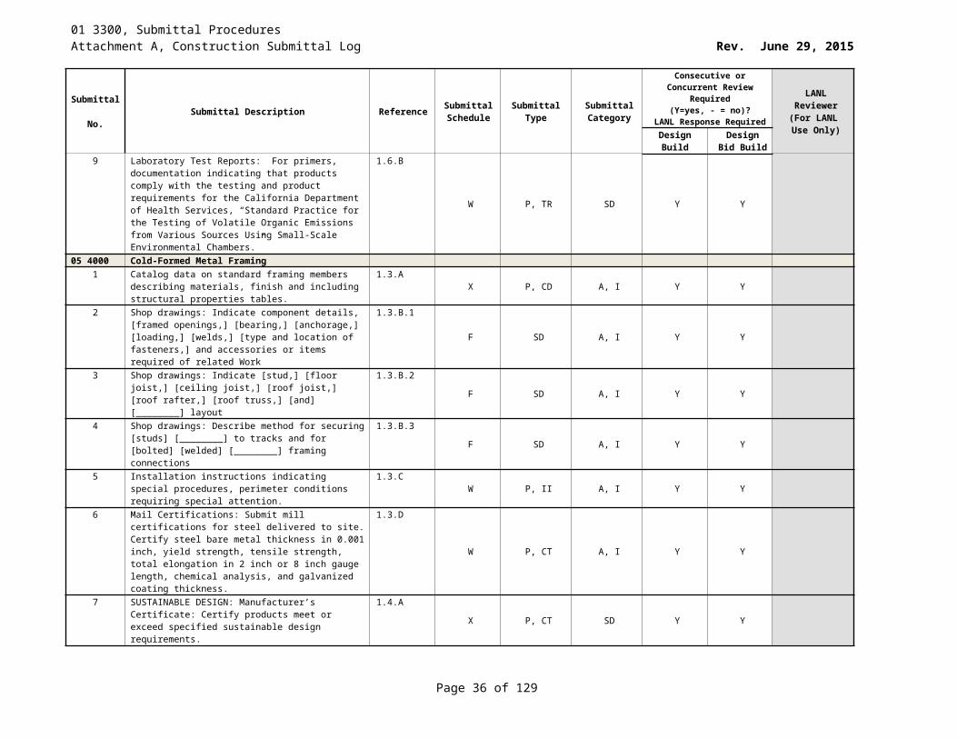
01 3300, Submittal ProceduresAttachment A, Construction Submittal Log Rev. June 29, 2015
Submittal No. Submittal Description Reference Submittal
ScheduleSubmittal
TypeSubmittal Category
Consecutive or Concurrent Review Required (Y=yes, - = no)?
LANL Response Required
LANL Reviewer
(For LANL Use Only)Design
BuildDesign Bid
Build9 Qualification data 1.3.I W P, CD A - -10 Product data 1.4.A X P, SD - -11 Manufacturer’s certificate 1.4.B X CT, P SD - -12 Volatile organic compound (VOC) compliance
certifications1.4.C X CT, P SD - -
13 Warranty 1.5.A At closeout P, WA C - -
08 1100 Metal Doors and Frames1 Catalog data 1.3.A.1 X P, CD A - -2 Certifications 1.3.A.2 W P, CT A - -3 Shop drawings for fabrication and installation of steel door
and frames.1.3.A.3 F SD A - -
08 1213 Hollow Metal Frames1 Catalog data 1.2.A.1 X P, CD A - -2 Certifications 1.2.A.2 W P, CT A - -3 Shop drawings 1.2.A.3 F D A - -
08 1400 Wood Doors1 Catalog data 1.2.A.1 X P, CD A - -2 LEED Submittals (if claiming credits) 1.2.A.2 X P SD - -3 Color and finish samples 1.2.A.3 X S,SC A Y Y4 Shop drawings 1.2.A.4 F SD A - -5 Warranty 1.2.A.5 at closeout P, WA A - -
08 3100 Access Doors and Panels1 Catalog data 1.2.A.1 X P, CD A - -2 Manufacturer’s installation instructions 1.2.A.2 W P, II A - -3 Schedule 1.2.A.3 W P A - -
08 3323 Overhead Coiling Doors1 Catalog data 1.3.A.1 X P, CD A - -2 Shop drawings 1.3.A.2 F SD A - -3 Manufacturer’s installation instructions 1.3.A.3 W P, II A - -4 Operation and maintenance data 1.3.A.4 at closeout P, OM A - -5 Manufacturer’s standard labor and material warranty 1.3.A.5 at closeout P, WA A - -
08 4113 Aluminum-Framed Entrances and Storefronts1 Catalog data 1.4.A.1 X P, CD A - -2 Calculations or load tables 1.4.A.2 F P, CA A - -3 Shop drawings 1.4.A.3 F SD A Y Y4 Samples 1.4.A.4 X (2)S A - -5 Manufacturer’s standard warranty 1.4.A.5 at closeout P A - -
08 5113 Aluminum Windows1 Catalog data 1.4.A.1 X P, CD A - -2 Shop drawings 1.4.A.2 W D A Y Y3 Warranty 1.4.A.3 Z P, WA A - -
08 7100 Door Hardware1 Catalog data 1.5.A.1 X P, CD A - -2 Materials list of final hardware schedule 1.5.A.2 X P A - -3 Final Hardware schedule 1.5.A.3 X P A Y Y
Page 36 of 83
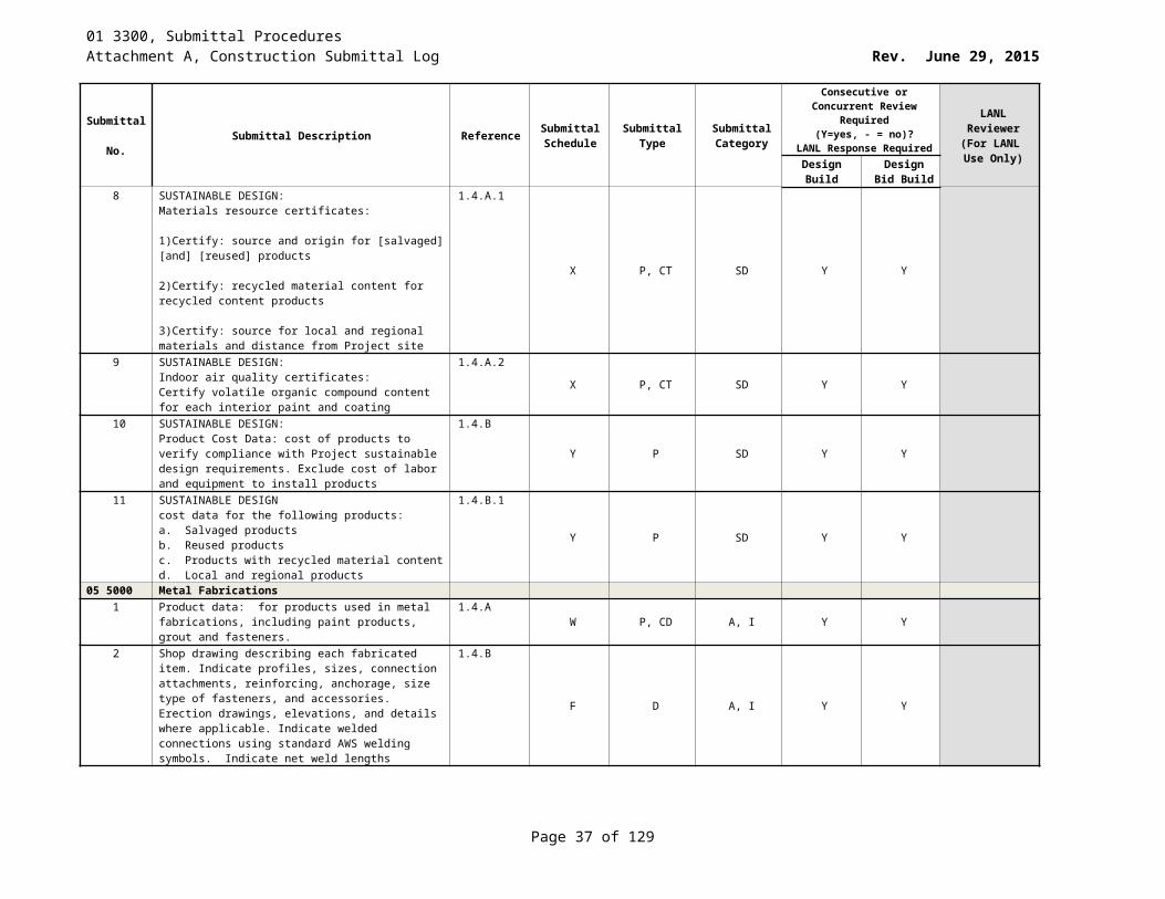
01 3300, Submittal ProceduresAttachment A, Construction Submittal Log Rev. June 29, 2015
Submittal No. Submittal Description Reference Submittal
ScheduleSubmittal
TypeSubmittal Category
Consecutive or Concurrent Review Required (Y=yes, - = no)?
LANL Response Required
LANL Reviewer
(For LANL Use Only)Design
BuildDesign Bid
Build4 Submittal sequence 1.5.A.4 F P, D A - -5 5 year warranty on materials and installation workmanship 1.5.A.5 at closeout WA A - -6 Manufacturer’s standard materials and workmanship 2 yr.
warranty 1.5.A.6 at closeout WA A - -
7 Complete set of specialized tools and maintenance instructions
1.5.A.7 Z P A - -
08 8000 Glazing1 Catalog data on glass types 1.3.A.1 X P A Y Y2 Catalog data on glazing compounds 1.3.A.2 X P A - -3 Manufacturer’s certs that glazing meets or exceeds
requirements.1.3.A.3 W P A - -
4 Glazing compound manufacturer’s installation instructions 1.3.A.4 W P A - -5 LEED: Product Data for Credit EQ 4.1 1.3.A.5 X P SD - -6 Samples of only special types of glass 1.3.A.6 Z S A - -7 Three inch long beads of glazing sealant for color
selection1.3.A.7 X (S) A - -
8 Manufacturer’s standard labor and material replacement warranty
1.3.A.8 at closeout P A - -
08 9100 Louvers1 Catalog data product criteria 1.3.A.1 X P A - -2 Manufacturer’s installation instructions 1.3.A.2 W P A - -3 Samples of color charts for metal and screen 1.3.A.3 X S A Y Y4 Shop drawings of component details, framed openings,
bearing, and anchor location of fasteners and accessories1.3.A.4 F SD A Y Y
09 2116 Gypsum Board Systems1 Catalog data 1.2.A.1 X P, CD A - -2 Gypsum manufacturer’s documentation of recycled
content for gypsum board1.2.A.2 X P A - -
3 Gypsum manufacturer’s documentation of buyback and/or recycling program
1.2.A.3 X P A - -
4 Manufacturer’s written certification that all materials are free of asbestos
1.2.A.4 W P, CT A - -
5 Manufacturer’s installation instructions 1.2.A.5 W P, II A - -6 Twelve inch square sample 1.2.A.6 Z S A - -
09 2913 Gypsum Roof Board1 Product data 1.2.A X P A - -2 Shop drawings 1.2.B F SD A - -3 Certification 1.2.C W P, CT A - -
09 3013 Ceramic Tiling1 Samples of proposed tile 1.2.A.1 X S A Y Y2 Samples of grout material 1.2.A.2 X S A Y Y3 Manufacturer’s installation instructions 1.2.A.3 W P, II A - -
09 5100 Acoustical Ceilings1 [Product Data] 1.5.A X P A - -2 Shop Drawings 1.5.B F SD A - -
Page 37 of 83
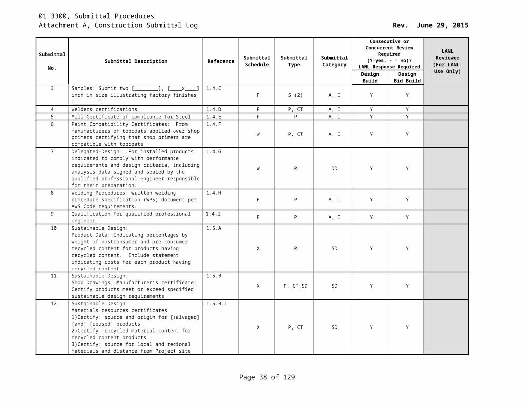
01 3300, Submittal ProceduresAttachment A, Construction Submittal Log Rev. June 29, 2015
Submittal No. Submittal Description Reference Submittal
ScheduleSubmittal
TypeSubmittal Category
Consecutive or Concurrent Review Required (Y=yes, - = no)?
LANL Response Required
LANL Reviewer
(For LANL Use Only)Design
BuildDesign Bid
Build3 [Samples: Submit two [____x___] inch in size of ceiling
grid and panel, illustrating finishes and color.]1.5.C X S(2) A Y Y
4 Manufacturer’s installation instructions 1.5.D W II, P A - -5 Manufacturer’s Certificate: Certify products meet or
exceed specified sustainable design requirements.1.6.A W CT, P SD - -
6 Materials Resources Certificates: 1. Certify source and origin for [salvaged] [and] [reused] products.2. Certify recycled material content for recycled content products.3. Certify source for local and regional materials and distance from Project site.
1.6.A.1
W CT, P SD - -
7 Indoor Air Quality Certificates: certify volatile organic compound content for each interior sealant and related primer.
1.6.A.2W CT, P SD - -
8 Operation and maintenance data 1.7.A At closeout O M C - -9 Warranty documentation 1.7.B At closeout WA C - -10 Project records documentation 1.7.C At closeout RD C - -11 Extra Stock Materials 1.8 - -12 Furnish [________] sq ft of extra [tile] [panels] [metal
pans] to the LANL Subcontract Technical Representative (STR), or
1.8.AAt closeout SP A - -
13 Furnish [________] percent of total acoustic unit area of extra [tile] [panels] [metal pans] to the LANL Subcontract Technical Representative (STR).
1.8.BAt closeout SP A - -
09 6500 Resilient Flooring1 Product data 1.3.A X P, S A Y Y2 Samples 1.3.B Z SC A Y Y3 Manufacturer’s installation instructions. 1.3.C W P, II A - -4 Sustainable Design: certification that percentage of
recovered materials will be at least equal to amount specified in Part 2 for applicable material
1.4.AX P, CT SD - -
5 Sustainable Design: Indoor air quality certificates 1.4.B X P, CT SD - -6 Closeout Submittals: Provide manufacturer’s cleaning and
maintenance information1.5 at closeout P C - -
7 Maintenance Material: At least 5% of calculated area of flooring materials of each type specified
1.6 at closeout P C - -
09 8613 Sheet Carpeting1 Catalog data 1.3.A.1 X P, CD A - -2 Manufacturer’s certificate 1.3.A.2 W P, CT A - -3 Manufacturer’s installation instructions 1.3.A.3 W P, II A - -4 Four carpet tiles 1.3.A.4 at closeout S A - -5 Shop drawings 1.3.A.5 F SD A Y Y6 Maintenance data 1.3.A.6 at closeout P C - -7 Project written warranty for all labor and materials, signed
by Subcontractor, Installer1.3.A.7 at closeout P A - Y
Page 38 of 83
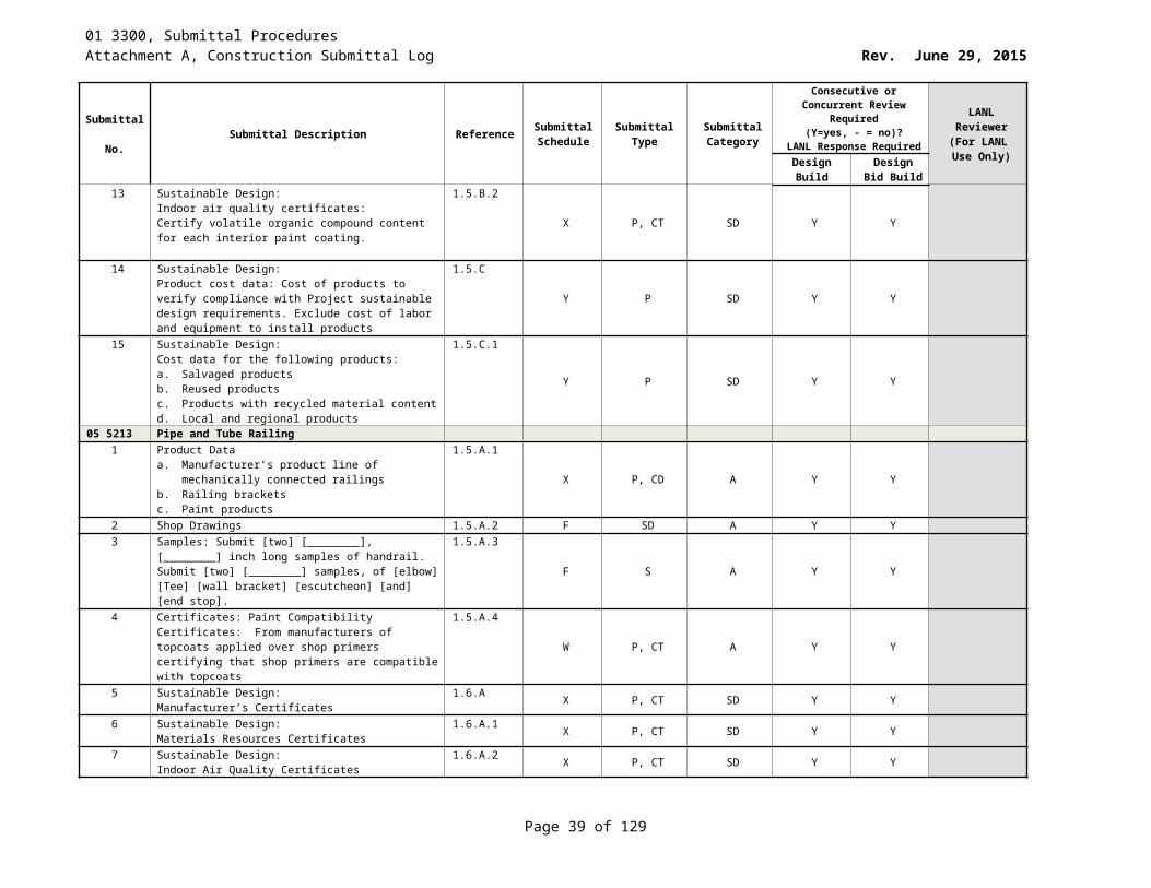
01 3300, Submittal ProceduresAttachment A, Construction Submittal Log Rev. June 29, 2015
Submittal No. Submittal Description Reference Submittal
ScheduleSubmittal
TypeSubmittal Category
Consecutive or Concurrent Review Required (Y=yes, - = no)?
LANL Response Required
LANL Reviewer
(For LANL Use Only)Design
BuildDesign Bid
Build09 6816 Sheet Carpeting A
1 Catalog data 1.2.A.1 X P, CD A - -2 Manufacturer's certificate 1.2.A.2 W P, CT A - -3 Manufacturer’s certificate 1.2.A.3 W P A - -4 Four 12 by 12 inch samples 1.2.A.4 X (4)S A - -5 Shop drawings 1.2.A.5 F SD A Y Y6 Maintenance procedures 1.2.A.6 at closeout P C - -7 Project warranty for all labor and materials, signed by
Subcontractor, Installer and Manufacturer 1.2.A.7 at closeout P A - Y
09 6900 Access Flooring1 Product Data: Unless providing exactly as specified,
submit data for grid system, panels, and accessories; electrical resistance characteristics and ground connection requirements
1.4.A
X P, CD A - -
2 Shop Drawings 1.4.B F P, CT A Y Y3 Samples: Submit two [____x____] inch in size of floor grid
and panel, illustrating finishes and color.]1.4.C X P, II A - -
4 Manufacturer's Certificate: Certify products meet or exceed specified requirements.
1.4.D W S A - Y
5 [Delegated Design Submittals: Seismic design calculations, bearing the seal of a licensed New Mexico Professional Engineer, demonstrating that the proposed floor systems meets requirements for seismic performance.]
1.4.E
F SD DD - -
6 Manufacturer's Installation Instructions: Submit special procedures, perimeter conditions requiring special attention, and [________]
1.4.FW P A - -
Sustainable Design Submittals: 1.5 X OT SD - -7 Manufacturer's Certificate: Certify products meet or
exceed specified sustainable design requirements1.5.A X P, CT SD - -
8 Materials Resources Certificates 1.5.A.1 X P, CT SD - -9 Certify source and origin for [salvaged] [and] [reused]
products1.5.A.1.a X P SD - -
10 Certify recycled material content for recycled content products.
1.5.A.1.b X P SD - -
11 Certify source for local and regional materials and distance from Project site.
1.5.A.1.c X P SD - -
12 Indoor Air Quality Certificates: Certify volatile organic compound content for each interior [adhesive] [and] [sealant] and related primer.
1.5.A.2X CT SD - -
13 Operation and Maintenance Data 1.6.A At closeout O M C - -14 Warranty Documentation 1.6.B At closeout WA C - -15 Project Records Documentation 1.6.C At closeout RD C - -
09 9100 Painting1 Catalog data 1.3.A.1 X P,SC A Y Y2 Qualification Data 1.3.A.2 W P, CD A - -
Page 39 of 83
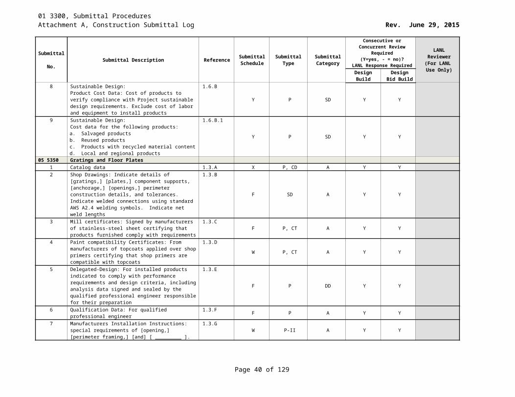
01 3300, Submittal ProceduresAttachment A, Construction Submittal Log Rev. June 29, 2015
Submittal No. Submittal Description Reference Submittal
ScheduleSubmittal
TypeSubmittal Category
Consecutive or Concurrent Review Required (Y=yes, - = no)?
LANL Response Required
LANL Reviewer
(For LANL Use Only)Design
BuildDesign Bid
Build3 Samples 1.3.A.3 X P,SC A - -4 Sustainable Design: Certificate of compliance for specified
post-consumer content1.3.B.1 X P, CT SD - -
5 Sustainable Design: List the VOC content of each product 1.3.B.2 X P SD - -6 Maintenance Material: Provide 1 extra gallon of each type,
color, and surface texture to LANL with location ID1.3.C.1.a at closeout OT C - -
10 1100 Visual Display Surfaces1 Catalog data on marker board, tack board surface
covering, trim and accessories.1.3.A.1 X P A - -
2 Tack board material color chart 1.3.A.2 X S A Y Y3 Manufacturer’s installation instructions. 1.3.A.3 W P A - -4 Maintenance information 1.3.A.4 at closeout P C - -
10 1405 Signage, Exterior1 Product Data 1.3.A X P A - -2 Shop drawings 1.3.B F SD A Y Y3 Samples 1.3.C X P,SC A - -4 Manufacturer’s recommended care and cleaning methods
including precautions against harmful cleaning materials and methods
1.4.Aat closeout P C - -
5 Manufacturer’s warranty documents 1.4.B at closeout P, WA C - -10 1410 Signage, Interior
1 Shop drawings 1.3.A F SD A Y Y2 Samples 1.3.B X P,SC A - -3 Schedule of Signs 1.3C F P A Y Y4 Manufacturer’s recommended maintenance methods 1.4.A at closeout P C - -5 Manufacturer’s warranty documentation 1.4.B at closeout P, WA C - -6 Template file to end-user as described in 2.2E.b 1.4.C at closeout OT C - -7 Maintenance Materials
template file to end-user as described in 2.2E.b below1.5.A at closeout OT C - -
8 Maintenance Materials six (6) suction cup tools for changing inserts in the aluminum frame
1.5.Bat closeout OT C - -
10 2113.13 Metal Toilet Compartments1 Product data 1.4.A.1 X P A - Y2 Shop drawings 1.4.A.2 F SD A Y Y3 Submit Samples 1.4.A.3 X P,S A - -
10 2800 Toilet & Bath Accessories1 Product Data
1. Construction details and dimensions.2. Anchoring and mounting requirements, including
requirements for cutouts in other work and substrate preparation.
3. Material and finish descriptions. 4. Features that will be included in Project. 5. Manufacturer’s warranty.
1.5.A
X P A - -
Page 40 of 83
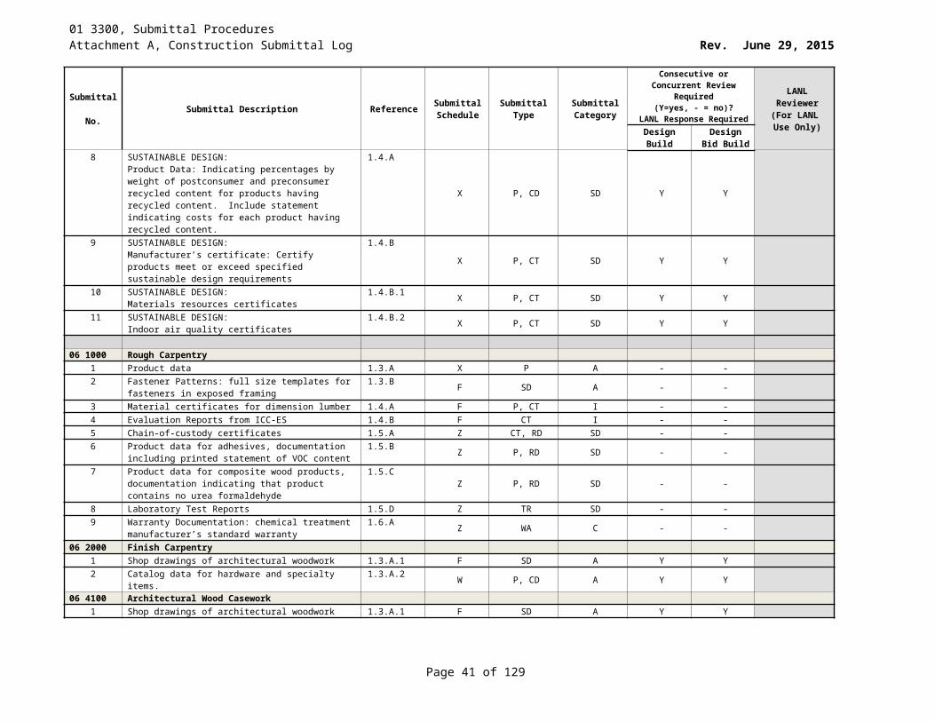
01 3300, Submittal ProceduresAttachment A, Construction Submittal Log Rev. June 29, 2015
Submittal No. Submittal Description Reference Submittal
ScheduleSubmittal
TypeSubmittal Category
Consecutive or Concurrent Review Required (Y=yes, - = no)?
LANL Response Required
LANL Reviewer
(For LANL Use Only)Design
BuildDesign Bid
Build2 [Samples: full size, for each accessory item to verify
design, operation, and finish requirements.1.5.B X S A - -
3 Product Schedule: indicating types, quantities, sizes and installation locations by room of each accessory required.
1.5.C W OT A - -
4 Manufacturer’s Certificate: certify products meet or exceed specified sustainable design requirements.
1.6.A X CT SD - -
5 Materials Resources certificates. 1.6.A.1 X P, CT SD - -6 Indoor Air Quality Certificates. 1.6.A.2 X P, CT SD - -7 Warranty: Sample of special warranty 1.7.A At closeout WA I - -8 Maintenance data: for toilet and bath accessories to
include in maintenance manuals.1.8.A At closeout M C - -
10 4400 Fire Protection Specialties1 Catalog data 1.2.A.1 X P, CD A - Y2 Shop drawings 1.2.A.2 F SD A - Y
10 5113 Metal Lockers1 Catalog data 1.2.A.1 X P, CD A - -2 Color chart 1.2.A.2 X P,SC A Y Y3 Manufacturer’s installation instructions 1.2.A.3 W P, II A - -4 Shop drawings 1.2.A.4 F SD A - -
11 1313 Loading Dock Bumpers1 Catalog data 1.2.A.1 X P A - -2 Manufacturer’s installation instructions. 1.2.A.2 W P, II A - -
11 5311.08 Glovebox Design1 Submittals listed in Att.4 and in accordance w the
requirements of Exh I – Lower Tier Services Plan 1.7.B Z P A Y Y PE
11 5311.10 Glovebox Fabrication1 Submittals listed in Att.2 1.7 & 1.8 Z P A - -
11 5311.12 Glovebox Installation1 Submittals in accordance with the requirements of Exh I 1.6.B Z P A - -2 Certified Material Test Report or Certificates of
Conformance.1.6.C W P, CT,TR A - -
3 Submittals detailed in Quality Assurance 1.6.D W P A - -4 QA Manual 1.7.A W P A Y Y5 Address the following in the supplier QA Manual. 1.7.B W P A - -6 Fabrication and Quality Control (QC) Procedures 1.7.B.1 F P A - Y7 Personnel Certifications. 1.7.B.2 F P A Y Y PE8 Test Reports. 1.7.B.3 F P, TR A Y Y PE9 Material Certifications. 1.7.B.4 F P, CT A - -10 As-Built Drawings. 1.7.B.5 Z D A - -11 QA Document Package. 1.7.B.6 w/shipment (3)P A - -12 Torque Maps. 1.7.B.7 w/shipment D A - -13 Weld Map. 1.7.B.8 w/shipment D A - -
11 5311.14 Glovebox Gloves1 Description of Quality Assurance program and procedures
to LANL 1.5.B.1 SANN P A - -
Page 41 of 83
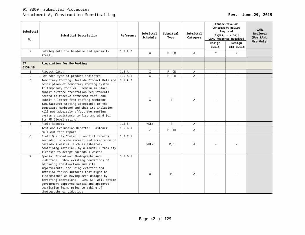
01 3300, Submittal ProceduresAttachment A, Construction Submittal Log Rev. June 29, 2015
Submittal No. Submittal Description Reference Submittal
ScheduleSubmittal
TypeSubmittal Category
Consecutive or Concurrent Review Required (Y=yes, - = no)?
LANL Response Required
LANL Reviewer
(For LANL Use Only)Design
BuildDesign Bid
Build2 Certificate of Conformance. 1.5.C.1 w/shipment P A - -3 Lot test results 1.5.D.1 w/shipment P A - -4 Material continuity 1.5.D.1.a F ML A - -5 Visual inspection 1.5.D.1.b w/shipment OT A - -6 Air tightness 1.5.D.1.c w/shipment OT A - -7 Resistance to nitric acid 1.5.D.1.d F OT A - -8 Aging tests 1.5.D.1.e F OT A - -9 Results of mechanical properties testing 1.5.D.1.f F OT A - -10 Lead equivalency measurement 1.5.D.1.g ANN OT A - -11 Certification to applicable portions of the ASTM standards
D120, F1236, F6401.5.D.2 F CT, P A - -
12 5 pairs of gloves and prototype test results per Section 2.5.A.3.
1.5.E.1 w/shipment (5)P, S A - -
13 Verify compliance with all of the inspection. 1.5.E.2 U OT A - -14 Verify that the manufacturer has ensured that the
shipment of gloves. 1.5.E.3 U OT A - -
15 Maintain records of inspections. 1.5.F.1 Z OT A - -11 5311.16 Glovebox Feedthroughs, Hermetically Sealed
1 Product data 1.5.B X P A - -2 Design Data 1.5.C.1.a F P A - -3 Material certifications 1.5.C.2.a Z P, CT A - -4 Certified Material Test Reports (CMTR’s) 1.5.C.2.b Z P, TR A Y Y PE5 Documentation for potting material. 1.5.C.2.c Z P A - -6 Quality Assurance/Quality Control: Test Reports 1.5.C.3 Z OT, TR A - -7 Documentation. 1.5.C.3.a Z P A Y Y PE8 Test reports/data sheets 1.5.C.3.b Z P, TR A Y Y PE9 Manufacturer’s Instructions 1.5.C.4.a Z P, II A - -10 Qualification Statements 1.5.C.5 Z P A Y Y PE
11 5311.17 Glovebox Instrumentation1 Provide documentation of ISO 9001 certification 1.6.A.1 N CT A Y Y PE2 Provide a copy of QA plan identifying procurement,
design, fabrication, test and inspection, material traceability and non-conformity controls for approval by LANL prior to subcontract award
1.6.A.2
N RD, P A Y Y PE
3 Catalog data and certificates of conformance (COC) for all instrumentation.
1.6.A.3 Z CD A Y Y PE
4 Provide CMTRs (alloy designations) for all process-wetted surfaces, consisting of legible copies of mill test reports indicating chemical analysis, physical test data, and heat number. COCs may be provided in lieu of CMTRs with prior LANL approval.
1.6.A.4
F P, TR A Y Y PE
5 Calibration certification traceable to NIST standards for all instrumentation
1.6.A.5 Z CT A Y Y PE
6 Detailed installation instructions for the model of instrument supplied.
1.6.A.6 Z II A - -
7 Functional test procedures and reports for all instrumentation.
1.6.A.7 Z TR A - -
Page 42 of 83
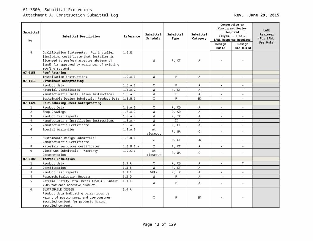
01 3300, Submittal ProceduresAttachment A, Construction Submittal Log Rev. June 29, 2015
Submittal No. Submittal Description Reference Submittal
ScheduleSubmittal
TypeSubmittal Category
Consecutive or Concurrent Review Required (Y=yes, - = no)?
LANL Response Required
LANL Reviewer
(For LANL Use Only)Design
BuildDesign Bid
Build8 Manufacturer’s operation and maintenance instructions for
the model of instrument supplied.1.6.A.8 Z O, M C - -
9 Helium leak test report for all instruments located outside the glovebox boundary and interfacing with the glovebox atmosphere. Provide test reports with signatures by personnel who either performed or witnessed the helium leak test and who hold either Level II or Level III certification in accordance with ASNT SNT-TC-1A.
1.6.A.9
Z TR A Y Y PE
10 Operating procedures, maintenance procedures, service schedules, recommended spare parts, and warranties.
1.6.A.10 Z O, M, OT, SP, WA C - -
11 Manufacturer’s assembly drawings, wiring diagrams, and electrical schematics.
1.6.A.11 Z D, ED A - -
11 5311.18 Glovebox Atmosphere Regenerable Purification Systems
1 ISO 9001 certification in accordance with Section 1.6 1.5.A.1 Z OT, CT A Y Y PE2 Uncontrolled copy of the supplier’s QA plan. 1.5.A.2 Z P A - Y3 Helium leak test 1.5.A.3 Z OT, TR A Y Y PE4 Helium leak test procedure per ASTM E498 1.5.A.4 F OT A - -5 Test reports with signatures by personnel 1.5.A.5 Z O, TR A Y Y PE6 NDE certifications for test personnel for approval, prior to
testing1.5.A.6 W CT A Y Y PE
7 CMTRs (alloy designations) 1.5.A.7 F P A - -8 Calibration data 1.5.A.8 W P A - -9 Circuit wiring diagrams and electrical schematics 1.5.A.9 Z D A Y Y PE10 Supplier's installation instructions 1.5.A.10 Z II, P A - -11 Functional test procedure 1.5.A.11 W P A - -12 Catalog data 1.5.A.12 X CD, P A Y Y PE13 Performance Data/Curves 1.5.A.13 Z PD A Y Y PE14 Documentation of cleaning techniques 1.5.A.14 Z P A - -15 Drawings 1.5.A.15 Z (3)D A Y Y PE16 Operation and maintenance instructions 1.5.A.16 S (2) P C - -
11 5311.19 Chemical Resistant Coatings for Gloveboxes1 Product Data: Manufacturer’s technical data for specified
coating.1.5.A W P A Y Y
2 Installation Instructions: Manufacturer's literature indicating installation Sections and procedures for specified coating
1.5.BW II, P A Y Y
3 Procedures: As listed under Para 1.9 Quality Assurance and Quality Control.
1.5.C W P A Y Y
4 Material Certifications: As listed under paragraph 1.9 Quality Assurance and Quality Control.
1.5.D W CT, P A Y Y
5 Samples: Three sample coupons that have been coated per this Section. The coupons must be 6" x 6" and constructed of 7 gauge 304L stainless steel. One side of the coupon must be coated with specified coating and the other side masked or polished to match original finish
1.5.E
W S A Y Y
Informational Submittals
Page 43 of 83
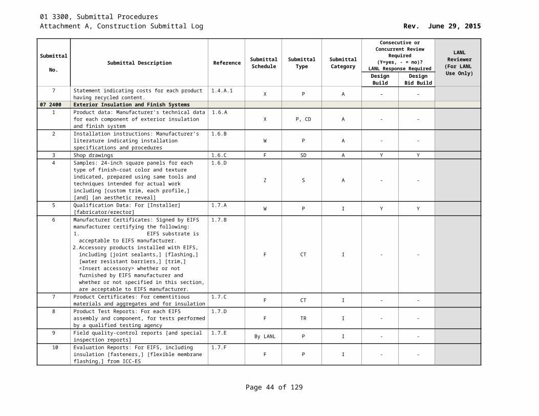
01 3300, Submittal ProceduresAttachment A, Construction Submittal Log Rev. June 29, 2015
Submittal No. Submittal Description Reference Submittal
ScheduleSubmittal
TypeSubmittal Category
Consecutive or Concurrent Review Required (Y=yes, - = no)?
LANL Response Required
LANL Reviewer
(For LANL Use Only)Design
BuildDesign Bid
Build6 As listed under paragraph 1.9 Quality Assurance and
Quality Control: Personnel certifications Test reports Inspection reports Dimensional inspection reports Supplier certifications
1.6.A
W CT, TR I Y Y
7 Certificate of Conformance: A certificate of conformance must be provided and signed by the Subcontractor. This certificate must state that the glovebox coatings have been applied and tested in accordance with this Section and, if applicable, the Subcontract documents and that the final product fully complies with all technical requirements of the Subcontract.
1.6.B
W CT I Y Y
Sustainable design submittals8 Manufacturer's Certificate: Certify products meet or
exceed specified sustainable design requirements. 1.7.A W CT SD Y Y
9 Product Data: For coating and primer, documentation including printed statement of VOC content.
1.7.B W P SD Y Y
10 Laboratory Test Reports: For coating and primer, documentation indicating that products comply with testing and product requirements of 40 CFR 59, Subpart D (EPA Method 24) National Volatile Organic Chemical Emission Standards for Architectural Coatings, if met.
1.7.C
W TR SD Y Y
Closeout Submittals11 Shop Traveler: Completed document as listed under
paragraph 1.9 Quality Assurance and Quality Control.1.8.A S OT C Y Y
12 Quality Assurance Document Package: As listed under paragraph 1.9 Quality Assurance and Quality Control.
1.8.B S RD C Y Y
12 2113 Horizontal Louver Blinds1 Catalog data 1.3.A.1 X CD, P A - -2 Samples 1.3.A.2 X P,S A - -3 Manufacturer’s installation instructions 1.3.A.3 W P, II A - -
12 3100 Manufactured Metal Casework1 Catalog data 1.3.A.1 X P, CD A - -2 Manufacturer’s installation instructions 1.3.A.4 W P, II A - -3 Samples 1.3.A.3 X P,SC A - -4 Shop drawings 1.3.A.2 F D A - -5 Sustainable Design:
Manufacturer’s Certificates1.3.B.1 X P, CT SD - -
6 Sustainable Design:Materials Resources Certificates
1.3.B.1.a X P, CT SD - -
7 Sustainable Design:Indoor Air Quality Certificates
1.3.B.1.b X P, CT SD - -
8 Sustainable Design:Product Cost Data
1.3.B.2 Y P SD - -
Page 44 of 83
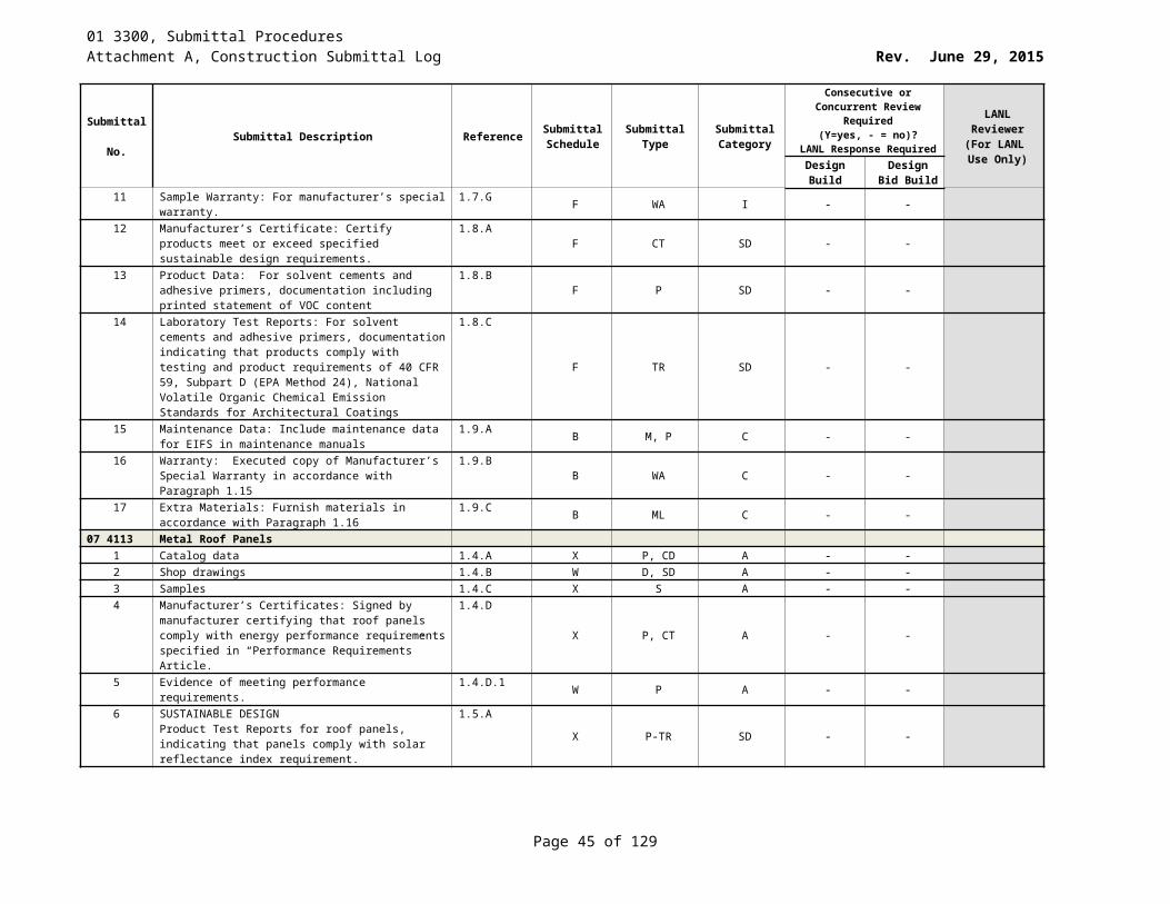
01 3300, Submittal ProceduresAttachment A, Construction Submittal Log Rev. June 29, 2015
Submittal No. Submittal Description Reference Submittal
ScheduleSubmittal
TypeSubmittal Category
Consecutive or Concurrent Review Required (Y=yes, - = no)?
LANL Response Required
LANL Reviewer
(For LANL Use Only)Design
BuildDesign Bid
Build9 Operations and Maintenance Data 1.3.C.1 at closeout OM C - -10 Manufacturer’s Warranty Documentation 1.3.C.2 at closeout P, WA C - -
13 3419 Metal Building Systems1 Product Data:
For each type of Metal Building System component. Include construction details, material descriptions, dimensions of individual components and profiles, and finished for the following: structural wall panels, metal roof panels, metal wall panels, metal liner panels, translucent panels
1.4.A
2 Shop drawings 1.4.B X P, D A Y Y3 Color samples 1.4.C.1 X P,SC A Y Y4 Samples for verification 1.4.C.2 X S A Y Y5 Certificates 1.4.D X P, CT A Y Y6 Erector Certificates: For each project, from manufacturer. 1.4.D.1 W P, CT A Y Y7 Manufacturers Certificates: For each product, from
manufacturer1.4.D.2 W P, CT A Y Y
8 Delegated Design Submittals 1.4.E W D DD Y Y9 Structural Basis document 1.4.E.1 W D DD Y Y10 Structural-Design calculations for the Metal Building, and
for the seismic design of the nonstructural components within / on it
1.4.E.2W D DD Y Y
11 Statement of Structural Tests and Special Inspections (i.e., Test and Inspection Plan per LANL ESM Chapter 16).
1.4.E.3W P DD Y Y
12 Anchor bolt placement plan, column reactions [,and] [______] in advance of erection drawings
1.4.E.4 W P DD Y Y
13 Test and evaluation Reports 1.4.F W P, TR A Y Y14 Material Test Reports 1.4.F.1 W P, TR A Y Y15 Product Test Reports 1.4.F.2 W P, TR A Y Y16 Source Quality-Control Reports 1.4.F.3 W P A Y Y17 Field Quality-Control Reports 1.4.F.4 WKLY P A Y Y18 Manufacturer’s installation instructions 1.4.G W P, II A Y Y19 Special procedures:
Surveys: Show final elevations and locations of major members. Indicate discrepancies between actual installation and the Subcontract Documents. Have surveyor who performed surveys certify their accuracy
1.4.H.1
Y P A Y Y
20 Qualification Data: For qualified [erector] [manufacturer] [professional engineer] [land surveyor] [testing agency].
1.4.I W P A Y Y
21 Sustainable Design:Manufacturer’s Certificate
1.5.A X P, CT SD Y Y
22 Sustainable Design:Sustainable Sites Certificates
1.5.A.1 X P, CT SD Y Y
23 Sustainable Design:Materials Resources Certificates
1.5.A.2 X P, CT SD Y Y
Page 45 of 83
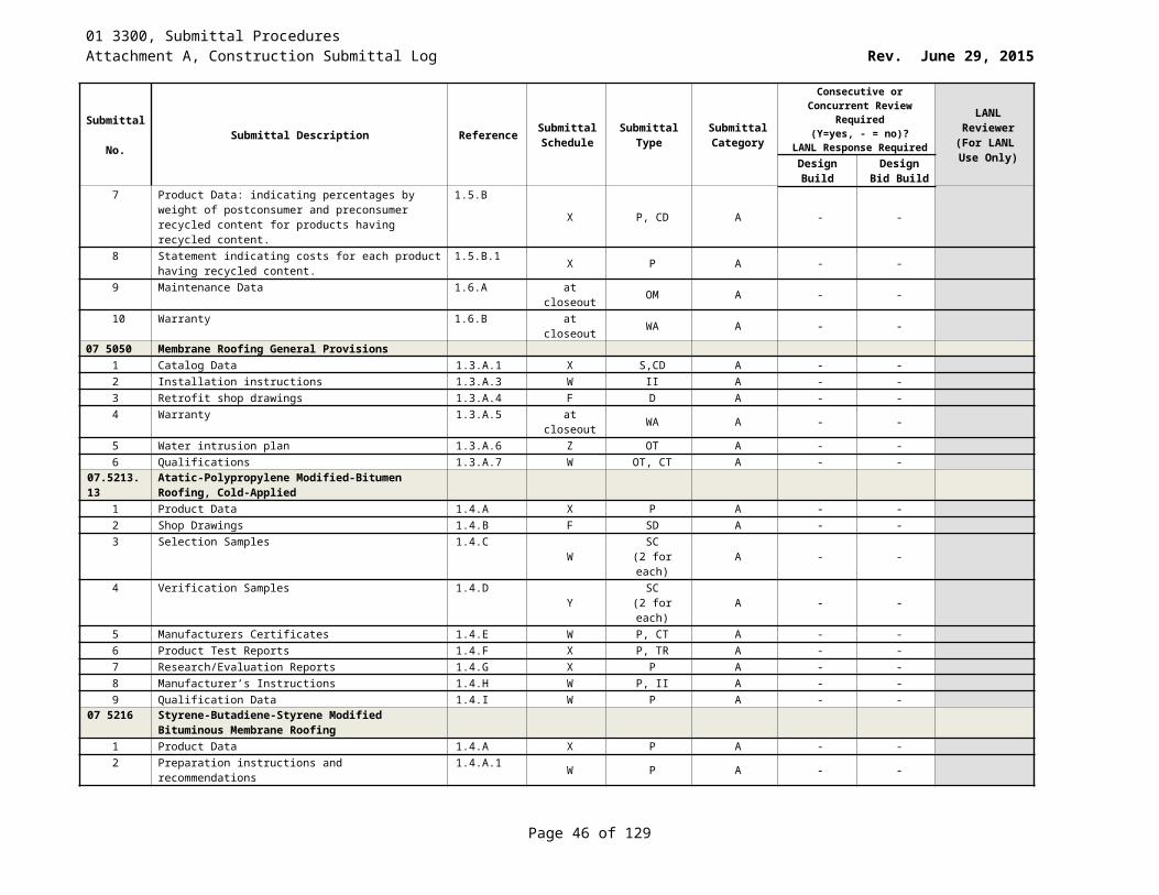
01 3300, Submittal ProceduresAttachment A, Construction Submittal Log Rev. June 29, 2015
Submittal No. Submittal Description Reference Submittal
ScheduleSubmittal
TypeSubmittal Category
Consecutive or Concurrent Review Required (Y=yes, - = no)?
LANL Response Required
LANL Reviewer
(For LANL Use Only)Design
BuildDesign Bid
Build24 Sustainable Design:
Indoor Air Quality Certificates1.5.A.3 X P, CT SD Y Y
25 Sustainable Design:Product Cost Data: Cost of products to verify compliance with Project sustainable design requirements. Exclude cost of labor and equipment to install products
1.5.B.1
Y P SD Y Y
26 Maintenance Data: for metal panel finishes, to include in maintenance manuals
1.6.A at closeout P, OM C Y Y
27 Warranties: Normal and special warranties 1.6.B at closeout WA C Y Y13 4800 Sound, Vibration, and Seismic Control
1 Catalog Data: Submit catalog data for each type of product specified. Include information substantiating equivalent corrosion resistance to zinc coated steel of alternative treatment, finish, or inherent material characteristic
1.4.A
X P, CD A Y Y
2 Certifications 1.4.B W P, CT A Y Y3 Shop Drawings: Templates, and erection and installation
details as appropriate for listed Items. Ensure details are complete, to include indication of metal thickness, type, grade, class, and dimensions. Show construction details, reinforcement, anchorage and installation with relation to building construction.
1.4.C
F D A Y Y
4 Documentation: Project Record Documents to include actual layout of supports / braces, specified certifications, and field test reports of anchorage installation
1.5.Aat closeout RD, P, D C Y Y
14 2413 Hydraulic Freight Elevators1 Catalog data: Signal and operating features 1.3.B.1 X P A - -2 Cab dimensions, layout and components 1.3.B.2 X P A - -3 Cab and hoistway doors and frames. 1.3.B.3 X P A - -4 Electrical characteristics 1.3.B.4 X P A - -5 Two samples, at least 2 inches square. 1.3.C X (2)S A - -6 Shop drawings: Motor & pump 1.3.D.1 F D A - -7 Shop drawings: car 1.3.D.2 F D A - -8 Shop drawings: rail bracket 1.3.D.3 F D A - -9 Shop drawings: weight of components. 1.3.D.4 F D A - -10 Shop drawings: loads 1.3.D.5 F D A - -11 Shop drawings: clearances 1.3.D.6 F D A - -12 Shop drawings: components 1.3.D.7 F D A - -13 Shop drawings: connections for car light and telephone. 1.3.D.8 F D A - -14 Shop drawings: locations and sizes of access doors,
doors and frames.1.3.D.9 F D A - -
15 Shop drawings: expected heat dissipation of elevator equipment
1.3.D.10 F D A - -
16 Shop drawings: applicable seismic design data 1.3.D.11 F D A - -17 Shop drawings: electrical characteristics 1.3.D.12 F D A - -18 Shop drawings: Show arrangement of equipment 1.3.D.13 F D A - -
Page 46 of 83
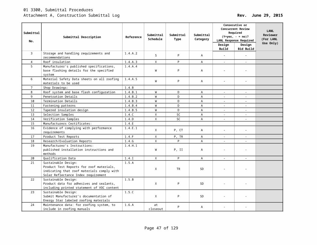
01 3300, Submittal ProceduresAttachment A, Construction Submittal Log Rev. June 29, 2015
Submittal No. Submittal Description Reference Submittal
ScheduleSubmittal
TypeSubmittal Category
Consecutive or Concurrent Review Required (Y=yes, - = no)?
LANL Response Required
LANL Reviewer
(For LANL Use Only)Design
BuildDesign Bid
Build19 Shop drawings: cab and hoist way door and frame details. 1.3.D.14 F D A - -20 Shop drawings: interface with building security system. 1.3.D.15 F D A - -21 Operation and Maintenance Data: 1.3.E22 Include a parts catalog 1.3.E.1 at closeout P C - -23 Technical information 1.3.E.2 at closeout P C - -24 Legible schematic of hydraulic piping and wiring diagrams 1.3.E.3 at closeout P C - -25 List of all of the elevator equipment with a description 1.3.E.4 at closeout P, PH C - -26 Complete sequence of operation and control 1.3.E.5 at closeout P C - -27 List with the name of the manufacturer 1.3.E.6 at closeout P C - -28 1 copy of master electric and hydraulic schematic and 1
copy of lubrication chart, each framed with clear plastic, mounted on machine room wall.
1.3.E.8at closeout (1)P, (1)P C - -
29 Test reports from independent elevator inspector per PART 3, Field Quality Control.
1.3.F Y P A Y Y PE
14 2423 Hydraulic Passenger Elevators1 Catalog data: Signal and operating features 1.3.B.1 X P A - -2 Catalog data: Cab dimensions, layout and components 1.3.B.2 X P A - -3 Catalog data: Cab and hoistway doors and frames. 1.3.B.3 X P A - -4 Catalog data: Electrical characteristics 1.3.B.4 X P A - -5 Two samples, at least 2 inches square 1.3.C X (2)S A - -6 Shop drawings: Motor and hydraulic pump 1.3.D.1 F SD A - -7 Shop drawings: Car, machine beams, guide rails, buffers 1.3.D.2 F SD A - -8 Shop drawings: rail bracket spacing 1.3.D.3 F SD A - -9 Shop drawings: individual weight of components 1.3.D.4 F SD A - -10 Shop drawings: loads 1.3.D.5 F SD A - -11 Shop drawings: clearances and overtravel of car. 1.3.D.6 F SD A - -12 Shop drawings: location of components in machine room. 1.3.D.7 F SD A - -13 Shop drawings: locations in hoistway and machine room
of connections for car light and telephone.1.3.D.8 F SD A - -
14 Shop drawings: locations and sizes. 1.3.D.9 F SD A - -15 Shop drawings: expected heat dissipation of elevator
equipment 1.3.D.10 F SD A - -
16 Shop drawings: applicable seismic design data 1.3.D.11 F SD A - -17 Shop drawings: electrical characteristics 1.3.D.12 F SD A - -18 Shop drawings: Show arrangement of equipment in
machine room 1.3.D.13 F SD A - -
19 Shop drawings: cab and hoist way door and frame details. 1.3.D.14 F SD A - -20 Shop drawings: interface with building security system. 1.3.D.15 F SD A - -21 Operation and Maintenance Data: 1.3.E at closeout OM C - -22 Include a parts catalog 1.3.E.1 at closeout P C - -23 Technical information 1.3.E.2 at closeout P C - -24 Legible schematic of hydraulic piping and wiring diagrams 1.3.E.3 at closeout P C - -25 List of all of the elevator equipment with a description, a
picture, and a current part number. 1.3.E.4 at closeout P, PH C - -
26 Complete sequence of operation and control of the elevator system
1.3.E.5 at closeout P C - -
Page 47 of 83
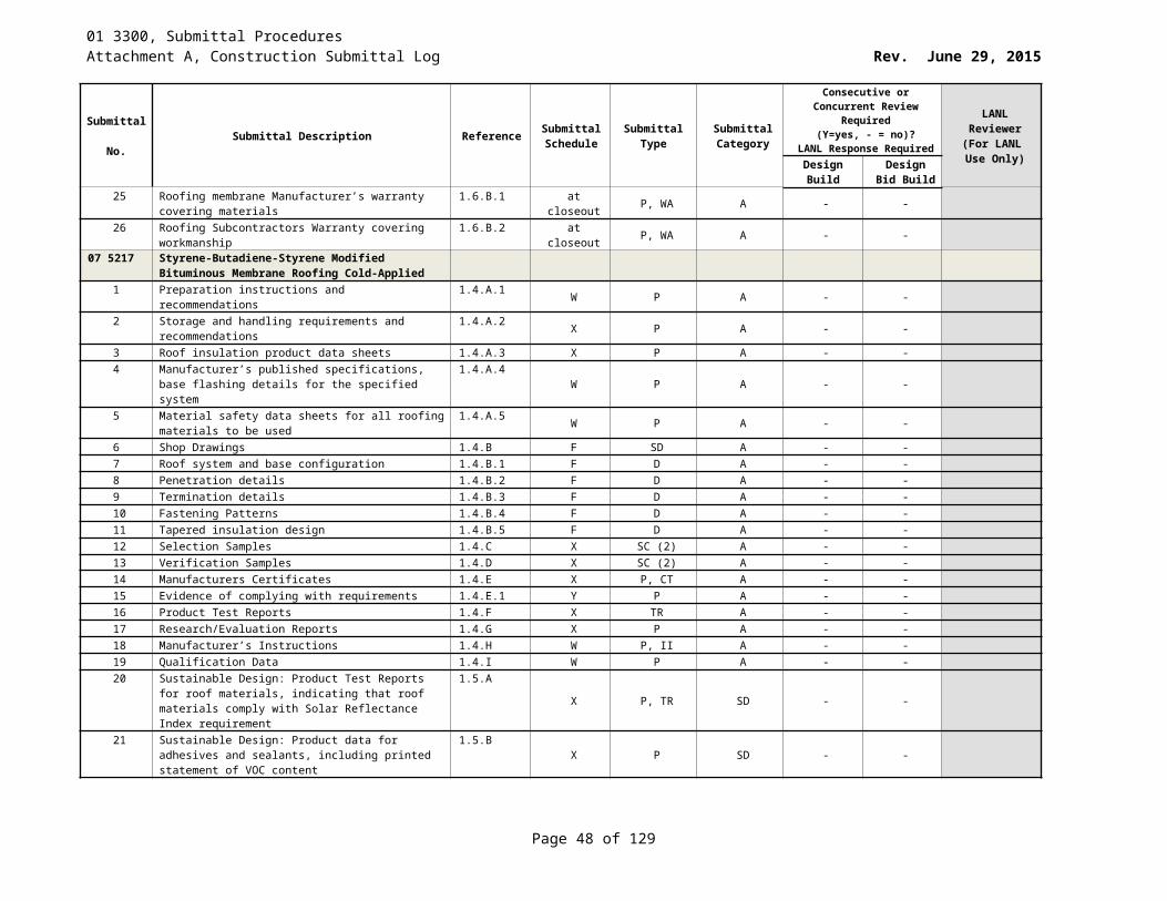
01 3300, Submittal ProceduresAttachment A, Construction Submittal Log Rev. June 29, 2015
Submittal No. Submittal Description Reference Submittal
ScheduleSubmittal
TypeSubmittal Category
Consecutive or Concurrent Review Required (Y=yes, - = no)?
LANL Response Required
LANL Reviewer
(For LANL Use Only)Design
BuildDesign Bid
Build27 List with the name of the manufacturer 1.3.E.6 at closeout P C - -28 1 copy of master electric and hydraulic schematic and 1
copy of lubrication chart, each framed with clear plastic, mounted on machine room wall.
1.3.E.8at closeout (1)P, (1)P C - -
29 Test reports from independent elevator inspector 1.3.F Y P A Y Y PE
21 1313 Wet-Pipe Sprinkler Systems1 Hydraulic Calculations with shop drawings. 1.4.A W P, D A Y Y2 Seismic Design Project Record Documents. Provide the
following:1.4.B W RD A Y Y
3 Calculations, prepared in accordance with LANL AP-341-605 or equivalent, that demonstrate compliance with 1.3.B.
1.4.B.1W P, CA A Y Y
4 Drawings, prepared in accordance with the LANL Drafting Standard, that convey the design to the constructor.
1.4.B.2 W D A Y Y
5 Test and Inspection Plan, prepared in accordance with LANL ESM Chapter 16, as necessary / applicable
1.4.B.3 W, Z OT A Y Y
6 Items a – c (above) shall be stamped and sealed by a PE licensed in the state of NM.
1.4.B.4 W O, OT A Y Y
7 Catalog Data with selected options marked. 1.4.C X P, CD A Y Y8 Certifications for welders 1.4.D F P A Y Y9 Installation Instructions 1.4.E W P, II A Y Y10 Materials Part List (Bill of Materials) 1.4.F W P A Y Y11 Shop Drawings 1.4.G F SD A Y Y12 Test Reports 1.4.H at closeout P, TR C Y Y13 Operation and Maintenance Manual: 1.4.I at closeout P, OM C Y Y14 Include in operation and maintenance manuals,
instructions, description of system, routine maintenance 1.4.I.1 at closeout P C Y Y
15 Also include in instructions, possible malfunctions 1.4.I.2 at closeout P C Y Y16 Describe function of each component or subassembly. 1.4.I.3 at closeout P C Y Y17 List recommended spare parts 1.4.I.4 at closeout P C Y Y18 Project Record Drawings (As-Built) on CD’s and prints
reflecting as-built conditions 1.4.J at closeout EM C Y Y
21 1316 Dry-Pipe Sprinkler Systems1 Hydraulic Calculations prepared in accordance with NFPA
13. Submit calculations with shop drawings.1.4.A W P, D A Y Y
Seismic Design Project Record Documents. Provide the following:
1.4.B W RD A Y Y
2 Calculations prepared in accordance with LANL AP-341-605, that demonstrate compliance with 1.3.B.
1.4.B.1 W P, CA A Y Y
3 Drawings prepared in accordance with the LANL Drafting Manual that convey the design to the constructor
1.4.B.2 W P, D A Y Y
4 Test and Inspection Plan, prepared in accordance with LANL ESM Chapter 16, as necessary / applicable.
1.4.B.3 W P A Y Y
5 Items 1-3 above shall be stamped and sealed by a PE licensed by New Mexico.
1.4.B.4 W O, OT A Y Y
Page 48 of 83
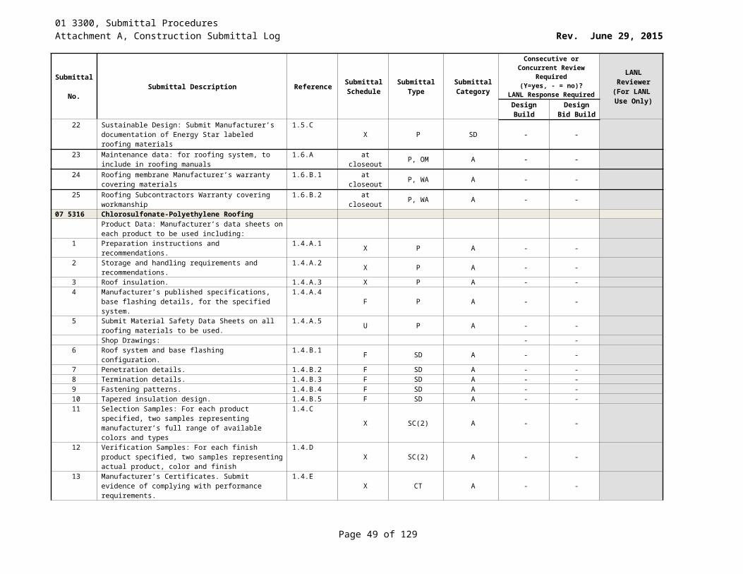
01 3300, Submittal ProceduresAttachment A, Construction Submittal Log Rev. June 29, 2015
Submittal No. Submittal Description Reference Submittal
ScheduleSubmittal
TypeSubmittal Category
Consecutive or Concurrent Review Required (Y=yes, - = no)?
LANL Response Required
LANL Reviewer
(For LANL Use Only)Design
BuildDesign Bid
Build6 Catalog Data with selected options marked. 1.4.C X P, CD A Y Y7 Certifications for welders in accordance with NFPA 13. 1.4.D W P, CT A Y Y8 Installation Instructions. 1.4.E W P, II A Y Y9 Materials Part List (Bill of Materials) with manufacturer,
model number and quantity.1.4.F W P A Y Y
10 Shop Drawings 1.4.G F SD A Y Y11 Test Reports 1.4.H at closeout P, TR A Y Y12 Operation and Maintenance Manual: Submit system
description, system final inspection, and Subcontractor’s material and test certificates
1.4.Iat closeout P C Y Y
13 Include in operation and maintenance manuals, instructions, description of system installed.
1.4.I.1 at closeout P C Y Y
14 Also include in instructions, possible malfunctions with diagnostic methods and suggested correction for each
1.4.I.2 at closeout P C Y Y
15 Describe function of each component or subassembly 1.4.I.3 at closeout P C Y Y16 List recommended spare parts 1.4.I.4 at closeout P C Y Y17 Project Record Drawings (as-builts) on CD’s and prints
reflecting as-built conditions 1.4.J at closeout P, EM C Y Y
18 Base as-built drawings on actual survey of the completed installation
1.4.J.1 at closeout D C Y Y
19 Include notes on all special systems or devices 1.4.J.2 at closeout P C Y Y20 Revised hydraulic calculations 1.4.J.3 at closeout P C Y Y
21 1319 Preaction Sprinkler Systems1 Hydraulic Calculations prepared in accordance with NFPA
13. Submit calculations with shop drawings.1.4.A.1 W P, CA A Y Y
Seismic Design Project Record Documents. Provide the following:
1.4.B. W D A Y Y
2 Calculations prepared in accordance with LANL AP-341-605, that demonstrate compliance with 1.3.B
1.4.B.1 W CA, P A Y Y
3 Drawings prepared in accordance with the LANL Drafting Manual that convey the design to the constructor
1.4.B.2 W D A Y Y
4 Test and Inspection Plan, prepared in accordance with LANL ESM Ch. 16, as necessary/applicable
1.4.B.3 W OT A Y Y
5 Items 1-3 above shall be stamped and sealed by a PE licensed by NM
1.4.B.4 W O, OT A Y Y
6 Catalog Data with selected options marked 1.4.C X P A Y Y7 Certifications for welders in accordance with NFPA 13 1.4.D W CT A Y Y8 Installation Instruction 1.4.E W P, II A Y Y9 Materials Part List (Bill of Materials) 1.4.F W P, ML A Y Y10 Shop Drawings 1.4.G F D A Y Y11 Test Reports 1.4.H WKLY P, TR A Y Y12 Operation and Maintenance Manual: Submit system
description, inspection and Subcontractor's material and test certificates
1.4.I.at closeout P C Y Y
13 Include in operation and maintenance manuals, instructions, description of system.
1.4.I.1 at closeout P C Y Y
Page 49 of 83
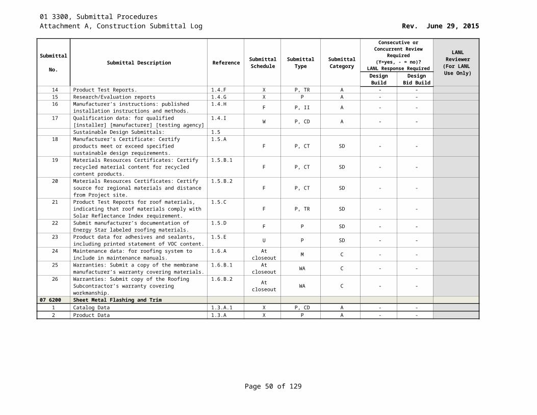
01 3300, Submittal ProceduresAttachment A, Construction Submittal Log Rev. June 29, 2015
Submittal No. Submittal Description Reference Submittal
ScheduleSubmittal
TypeSubmittal Category
Consecutive or Concurrent Review Required (Y=yes, - = no)?
LANL Response Required
LANL Reviewer
(For LANL Use Only)Design
BuildDesign Bid
Build14 Also include in instructions, possible malfunctions 1.4.I2 at closeout P C Y Y15 Describe function of each component or subassembly 1.4.I.3 at closeout P C Y Y16 Recommended spare parts 1.4.I.4 at closeout P C Y Y17 Project Record Drawings (As-Built) on CD’s and prints
indicating as-built conditions 1.4.J at closeout EM C Y Y
21 1326 Deluge Fire-Suppression Sprinkler Systems1 Hydraulic calculations, prepared in accordance with NFPA
13. Submit calculations with shop drawings.1.3.A.1 W P, CA A Y Y
2 Seismic Design Project Record documents: Provide the following:
1.3.B. W RD A Y Y
3 Calculations, prepared in accordance with LANL AP-341-605, that demonstrate compliance with 1.3.B
1.3.B.1 W CA A Y Y
4 Drawings, prepared in accordance with the LANL Drafting Manual, that convey the design to the constructor
1.3.B.2 W EM A Y Y
5 Test and Inspection Plan, prepared in accordance with LANL ESM Chapter 16, as necessary / applicable.
1.3.B.3 W P A Y Y
6 Items 1-3 above shall be stamped and sealed by a PE licensed by New Mexico.
1.3.B.4 W O, OT A Y Y
7 Catalog Data with selected options marked 1.3.C X P A Y Y8 Certifications for welders in accordance with NFPA 13 1.3.D F P A Y Y9 Installation Instructions 1.3.E W P A Y Y10 Materials Part List (Bill of Materials) 1.3.F W P A Y Y11 Shop Drawings w/ information required by NFPA 13 1.3.G F D A Y Y12 Test Reports 1.3.H WKLY P A Y Y13 Operation and Maintenance Manual with contents as
described1.3.I at closeout P C Y Y
14 Project Record Drawings (As-Built) on CD’s and prints indicating as-built conditions
1.3.J at closeout D, EM C Y Y
21 1339 Foam-Water Systems1 Hydraulic calculations, prepared in accordance with NFPA
13 and 16. Submit calculations with shop drawings.1.3.A.1 F P, CA A Y Y
Seismic design project record documents. Provide the following:
1.3.B W RD A Y Y
2 Calculations prepared in accordance with LANL AP-341-605 that demonstrate compliance with 1.3.B
1.3.B.1 W CA A Y Y
3 Drawings, prepared in accordance with the LANL Drafting Manual, that convey the design to the constructor.
1.3.B.2 F P, D A Y Y
4 Test and Inspection Plan, prepared in accordance with LANL ESM Chapter 16 as necessary/applicable.
1.3.B.3 F P A Y Y
5 Items 1-3 above shall be stamped and sealed by a PE licensed by NM
1.3.B.4 A Y
6 Catalog Data with selected options noted. 1.3.C X P, CD A Y Y7 Certifications for welders in accordance with NFPA 13 1.3.D F P, CT A Y Y8 Installation Instructions 1.3.E W P, II A Y Y9 Materials Part List (Bill of Materials) 1.3.F W P.ML A Y Y10 Shop Drawings 1.3.G F SD A Y Y
Page 50 of 83
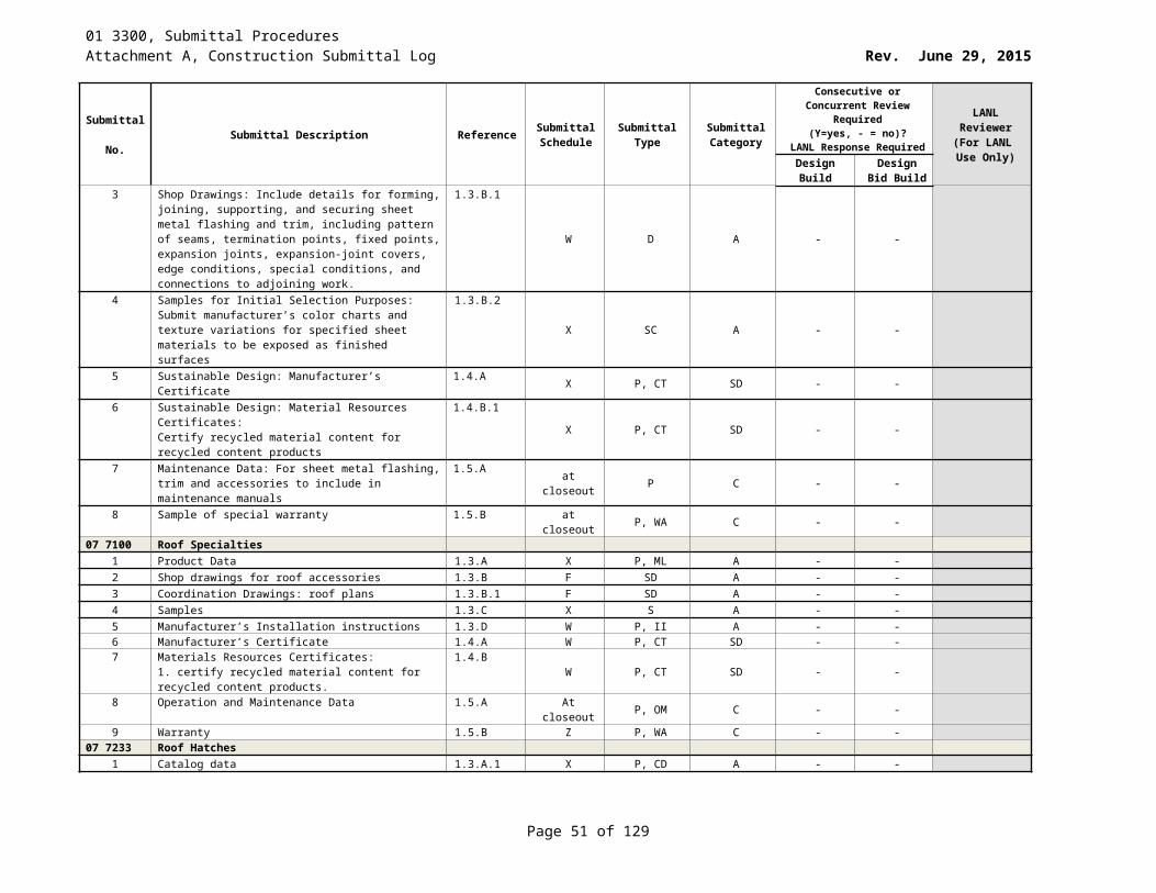
01 3300, Submittal ProceduresAttachment A, Construction Submittal Log Rev. June 29, 2015
Submittal No. Submittal Description Reference Submittal
ScheduleSubmittal
TypeSubmittal Category
Consecutive or Concurrent Review Required (Y=yes, - = no)?
LANL Response Required
LANL Reviewer
(For LANL Use Only)Design
BuildDesign Bid
Build11 Test Reports 1.3.H WKLY P, TR A Y Y12 Operation and Maintenance Manual: system description, 1.3.I at closeout P C Y Y13 Project Record Drawings (As-Built) on CD’s and prints
indicating as-built conditions 1.3.J at closeout D,EM C Y Y
21 2200 Clean Agent Fire-Extinguishing Systems1 Product data 1.3.A X P A Y Y2 Shop Drawings 1.3.B F D A Y Y3 Layout drawings 1.3.B.1 F D A Y Y4 Auxiliary details and information 1.3.B.2 F D A Y Y5 Separate layouts or drawings for mechanical and
electrical work.1.3.B.3 F D A Y Y
6 Separate layout or drawings showing isometric details 1.3.B.4 F D A Y Y7 Electrical layout drawings. 1.3.B.5 F D A Y Y8 Complete hydraulic flow calculations from a UL-listed
computer program. 1.3.B.6 F P, EM A Y Y
9 Drawings, calculations, and system component data sheets for approval before starting construction.
1.3.B.7 W P, D A Y Y
10 If seismic protection applies, then include: Seismic Calculations:
1.3.C W P A Y Y
11 Calculations based on a dynamic analysis certified by a registered professional engineer
1.3.C.1 W P A Y Y
12 Qualifications of dynamic analyst and documentation of computer software systems
1.3.C.2 W P, EM A Y Y
13 Catalog Data with selected options noted 1.3.D X P, CD A Y Y14 Materials Part List (Bill of Materials) 1.3.E W P A Y Y15 Test Reports 1.3.F WKLY P A Y Y16 Operation and Maintenance Manual: 1.4.A at closeout P C Y Y17 Project Record Drawings (As-Built): Provide updated shop
drawings on CDs and prints reflecting as-built conditions 1.4.B at closeout D,EM C Y Y
22 0529 Hangers and Supports for Plumbing Piping and Equipment
1 Catalog data of hangers and supports 1.2A.1 X P A - -2 Shop Drawings showing system layout with location
including critical dimensions, sizes, and pipe hanger and support locations and detail of trapeze hangers.
1.2A.2F SD A - -
3 Manufacturer’s installation instruction for special procedures and assembly of components if required.
1.2A.3 W P, II A - -
4 Certification of offsite welders and qualified welding procedure per Section 01 4444 (follow 01 4455 for onsite work).
1.2A.4F P, CT A - Y
22 0535 Electric Heat Tracing1 Catalog Data: Submit catalog data for heater cable,
thermostat, controls, fittings, indicator light, and pipe markers
1.2.A.1X P, CD A - -
Page 51 of 83
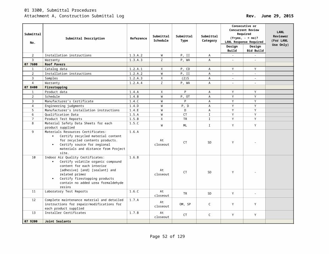
01 3300, Submittal ProceduresAttachment A, Construction Submittal Log Rev. June 29, 2015
Submittal No. Submittal Description Reference Submittal
ScheduleSubmittal
TypeSubmittal Category
Consecutive or Concurrent Review Required (Y=yes, - = no)?
LANL Response Required
LANL Reviewer
(For LANL Use Only)Design
BuildDesign Bid
Build2 Shop Drawings: composite wiring and/or schematic
diagrams of the complete system as proposed to be installed (standard diagrams will not be acceptable) as described.
1.2.A.2
F D A - -
3 Installation Instructions Indicate application conditions and limitations of use stipulated by Product testing agency specified under Regulatory Requirements. Include instructions for storage, handling, protection, examination, installation, and starting of Product.
1.2.A.3
W P, II A - -
4 Operation and Maintenance Instructions 1.2.A.4 at closeout P, OM C - -5 Warranty: Provide a 3-year parts warranty, on materials
and workmanship, and 1-year labor warranty beginning on the date of acceptance by LANL.
1.2.A.5at closeout P, WA C - -
6 Records of inspections, tests, and adjustments described under FIELD QUALITY CONTROL.
1.2.A.6 WKLY P A - -
22 0548 Vibration and Seismic Controls for Plumbing Piping and Equipment
1 Catalog data for each type of product specified 1.5.B X P A - -2 Materials List: Hanger and support schedule showing
manufacturer's figure number, size, spacing, features, and application for each required type of hanger, support, sleeve, seal, and fastener to be used
1.5.C
W P, ML A - -
3 Shop drawings showing details 1.5.D F SD A Y Y PE4 Certifications 1.5.E Z P A Y Y PE
22 0554 Identification for Plumbing, HVAC, and Fire Piping and Equipment
1 Catalog data 1.4.1 X P A Y Y PE2 Installation instructions 1.4.2 W P A - -
22 0713 Plumbing and HVAC Insulation1 Catalog data: Product description, thermal characteristics
and list of materials and thickness for each service, and location.
1.2.A.1X P, CD A Y Y PE
2 Manufacturer’s Installation Instructions 1.2.A.2 W P, II A - -22 0813 Testing Piping Systems
1 Test plan for approval that includes: material of construction, design pressure, test pressure and duration of test, test medium and method of achieving the test pressure, certification on calibration of pressure gauges, method to exclude personnel from the area containing the system to be tested, overpressurization protection/prevention.
1.3.A.1
W TR A Y Y PE
2 Test reports 1.3.A.2 DAY P, TR A Y Y PE22 0816 Disinfection of Potable Water Piping
1 Free chlorine concentration 1.3.A.1 DAY TR A Y Y2 Bacterial Quality Test 1.3.A.2 DAY TR A Y Y3 Residual chlorine concentration, after flushing chlorinated
water1.3.A.3 DAY TR A Y Y
Page 52 of 83
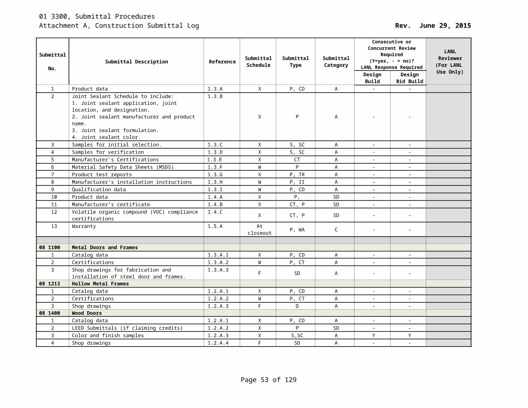
01 3300, Submittal ProceduresAttachment A, Construction Submittal Log Rev. June 29, 2015
Submittal No. Submittal Description Reference Submittal
ScheduleSubmittal
TypeSubmittal Category
Consecutive or Concurrent Review Required (Y=yes, - = no)?
LANL Response Required
LANL Reviewer
(For LANL Use Only)Design
BuildDesign Bid
Build4 Test reports 22 0816
1.3.B DAY TR A Y Y
22 1100 Facility Water Distribution1 Catalog data 1.2.A.1 X P, CD A - -2 Shop drawings showing pump type, capacity, certified
pump curves showing pump performance characteristics with pump and system operating point plotted. Include NPSH curve when applicable. Include electrical characteristics and connection requirements.
1.2.A.2
F SD A Y Y PE
3 Installation instructions 1.2.A.3 W P, II A - -22 1316 Sanitary Waste and Vent Piping
1 Catalog data 1.2.A.1 X P, CD A - -2 Manufacturer’s Instructions 1.2.A.2 W P, II A - -3 Certifications of welders 1.2.A.3 F P, CT A Y Y PE
22 1343.16 Facility Wet-Well Packaged Sewage Pumping Stations (Interior)
1 Catalog data 1.3.A.1 X P A Y Y PE2 Pump curves 1.3.A.2 X P A Y Y PE3 Operation and maintenance data 1.3.A.3 at closeout P C - -4 Theory of operation 1.3.A.3.a at closeout P C - -5 Test procedure 1.3.A.3.b Y P A - -6 Operating procedures 1.3.A.3.c at closeout P C - -7 Maintenance requirements 1.3.A.3.d at closeout P C - -8 Warranties 1.3.A.4 at closeout P C - -
22 1413 Facility Storm Drainage Piping1 Catalog data 1.2.A.1 X P, CD A - -2 Installation instructions 1.2.A.2 W P, II A - -3 Certifications of welders 1.2.A.3 F P, CT A Y Y PE
22 1500 Compressed-Air Systems1 Catalog data 1.2.A.1 X P, CD A Y Y2 Installation Instructions 1.2.A.2 W P, II A - -3 Materials/Parts list 1.2.A.3 W P, ML A Y Y4 Operational and maintenance data 1.2.A.4 at closeout P, OM C - -5 Warranties 1.2.A.5 at closeout P, WA A - -6 Certification of welders and qualified welding procedure
per Section [01 4444] [and] [01 4455].1.2.A.6 F P, CT A Y Y PE
7 Welding inspection reports 1.2.A.7 Z P A Y Y PE22 3700 Domestic Water Heaters
1 Product Data: For each type and size of water heater indicated, include rated capacities, operating characteristics, electrical characteristics, and furnished specialties and accessories. Include documentation indicating that units comply with applicable requirements in ASHRAE/IESNA 90.1, Section 7, Service Water Heating [or Energy Star]
1.3.A
X CD A Y Y PE
2 Shop Drawings: Wiring Diagrams for power, signal, and control wiring
1.3.B F SD A - -
Page 53 of 83
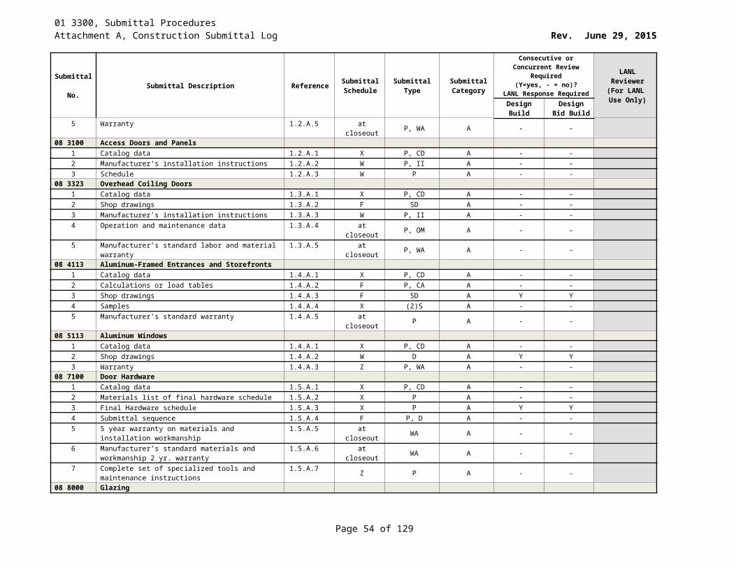
01 3300, Submittal ProceduresAttachment A, Construction Submittal Log Rev. June 29, 2015
Submittal No. Submittal Description Reference Submittal
ScheduleSubmittal
TypeSubmittal Category
Consecutive or Concurrent Review Required (Y=yes, - = no)?
LANL Response Required
LANL Reviewer
(For LANL Use Only)Design
BuildDesign Bid
Build3 Operation and Maintenance Data: Include emergency,
operation, and maintenance manuals1.3.C at closeout P, OM C - -
4 Certification of welders and qualified welding procedure per Sections [01 4444] [and] [01 4455]
1.3.D F P, CT A Y Y PE
5 Product Certificates: For each type of [electric,] [tankless,] [gas-fired] water heater from manufacturer
1.3.E X P, CT A Y Y PE
6 Warranty: Provide documentation of [One] [Three] [Five] [____] year warranty
1.3.F at closeout P, WA A - -
7 Test Reports: For each type of [electric,] [tankless,] [gas-fired] water heater. [Include factory test reports]
1.3.G WKLY P, TR A Y Y
8 Water Heater Labeling: Certified and labeled by testing agency acceptable to authorities having jurisdiction. [UL, AGA, ASME, ASHRAE, CSA, NSF]
1.3.Hat closeout P A Y Y PE
9 Indicate EER (Energy Efficiency Rating) or Energy Factor (EF) for equipment provided under work of this Section
1.3.I.1 X P, CT A Y Y PE
10 Submit documentation for Energy Star qualifications for equipment provided under work of this Section
1.3.I.2 X P, CT A Y Y PE
22 4200 Plumbing Fixtures1 Product Data 1.3.A. X S,P A Y Y PE2 Manufacturer's Installation Instructions. 1.3.B W P, II A - -3 Manufacturer's Certificate 1.3.C W P, CT A Y Y PE4 Contract Closeout 1.4.A at closeout P C - -5 Operation and Maintenance Data 1.4.B at closeout P C - -
23 0593 Testing, Adjusting, and Balancing for HVAC1 Date of expiration of AABC or NEBB certification 1.4.A.1 W P A Y Y PE2 TAB instruments that are to be used and calibration dates 1.4.A.2 W P A Y Y PE3 Proposed TAB procedures, together with the TAB
schematic drawings and Report Forms, for review.1.4.A.3 W P A Y Y PE
4 Field Reports indicating deficiencies preventing proper testing, adjusting, and balancing of systems and equipment to achieve specified performance.
1.4.A.4WKLY P A Y Y PE
5 Draft copies of test report for review prior to final acceptance TAB test result.
1.4.A.5 W P A Y Y PE
6 Final test reports 1.4.A.6 W P A Y Y PE23 1123 Facility Natural Gas Piping
1 Catalog data on pipe materials 1.2.A.1 X P, CD A - -2 Certification of welders 1.2.A.2 F P, CT A Y Y PE
23 2113 Hydronic Piping1 Catalog data on pipe materials, fittings, valves, and
accessories1.2.A.1 X P, CD A - -
2 Installation instructions for valves and accessories 1.2.A.2 W P, II A - -3 Welding procedures and qualifications. 1.2.A.3 F P A Y Y PE4 Certifications of welders and qualified welding procedures
per section [01 4444] [AND] [01 4455].1.2.A.4 F P, CT A Y Y PE
23 2215 Steam and Condensate Heating Piping and Specialties
Page 54 of 83
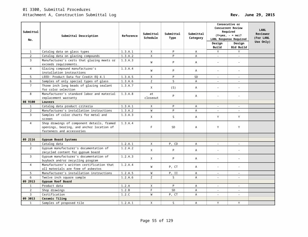
01 3300, Submittal ProceduresAttachment A, Construction Submittal Log Rev. June 29, 2015
Submittal No. Submittal Description Reference Submittal
ScheduleSubmittal
TypeSubmittal Category
Consecutive or Concurrent Review Required (Y=yes, - = no)?
LANL Response Required
LANL Reviewer
(For LANL Use Only)Design
BuildDesign Bid
Build1 Catalog data on pipe materials, pipe fittings, valves, and
piping specialties specified including electrical characteristics and connection requirements.
1.2.A.1X P, CD A Y Y PE
2 Product description, model, dimensions, component/service sizes, rough-in requirements, and finishes.
1.2.A.2X P A Y Y PE
3 Manufacturer’s catalog information with valve data and rating for each service
1.2.A.3 X P A Y Y PE
4 Certification of welders 1.2.A.4 F P, CT A Y Y PE23 2300 Refrigerant Piping
1 Catalog data: pipe materials, 1.2.A.1.a X P A Y Y2 Catalog data: Refrigerant Specialties 1.2.A.1.b X P A - -3 Manufacturer's Installation Instructions 1.2.A.2 W P, II A - -4 Operations and Maintenance Manual: operation and
maintenance instructions for refrigerant specialties1.2.A.3 at closeout P, OM C - -
5 Certification of welders 1.2.A.4 F P, CT A Y Y PE23 2500 HVAC Water Treatment
1 Catalog data of flushing and chemical water treatment 1.5.A.1 X P, CD A - -2 Shop Drawings indicating system schematic, equipment
locations, and controls schematics, electrical characteristics and connection requirements.
1.5.A.2F SD A - -
3 Manufacturer’s Installation Instructions showing placement of equipment in systems, piping configuration, and connection requirements.
1.5.A.3W P, II A - -
4 Manufacturer’s Certification of products to meet or exceed specified requirements.
1.5.A.4 X P, CT A - -
5 Operation and Maintenance data on equipment, procedures, and treatment program
1.5.A.5 at closeout P, OM C - -
6 Material list of all chemicals to be used. 1.5.A.6 W P A - -7 Manufacturer’s Field Reports: Indicate start-up of
treatment systems when completed and operating properly. Indicate analysis of system water after cleaning and after treatment.
1.5.A.7
WKLY P A - -
23 3101 HVAC Ducts1 Catalog data for duct materials, flexible duct/connectors,
sealing materials.1.2.A.1 X P, CD A Y Y PE
2 Shop drawings indicating duct layout with pressure classification and sizes, fittings, hangers and supports, [seismic restraints], seam and joint construction, connections to equipment such as coils, etc., for pressure class ducts [ ] inches and greater.
1.2.A.2
F SD A Y Y PE
3 Test Reports indicating pressure tests performed. Include date, section tested, test pressure, and leakage rate, following SMACNA HVAC Air Duct Leakage Test Manual.
1.2.A.3WKLY P, TR A Y Y PE
4 Certificates showing conformance with the applicable standards for ductwork materials, brazing materials, mill-rolled reinforcing and supporting materials, welding procedures, shop test procedures and reports.
1.2.A.4
Y P, CT A Y Y PE
Page 55 of 83
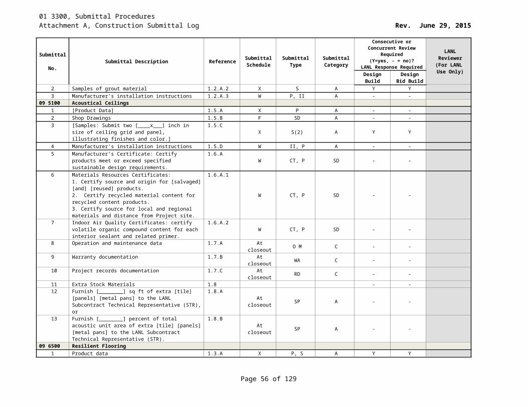
01 3300, Submittal ProceduresAttachment A, Construction Submittal Log Rev. June 29, 2015
Submittal No. Submittal Description Reference Submittal
ScheduleSubmittal
TypeSubmittal Category
Consecutive or Concurrent Review Required (Y=yes, - = no)?
LANL Response Required
LANL Reviewer
(For LANL Use Only)Design
BuildDesign Bid
Build5 Certification of welders and qualified welding procedure
per Section [01 4444] [and] [01 4455].1.2.A.5 F P, CT A Y Y PE
23 3225 Bag-in Bag-out Housings1 Fire Screen catalog data indicating materials of
construction and mesh size1.3.A.1.a X CD A Y Y PE
Prefilters 1.3.A.22 Catalog data indicating the filter efficiency and pressure
drop at rated capacity1.3.A.2.a X CD A Y Y PE
3 Certificate of Conformance (CoC) that the prefilter conforms to ASME AG-1, Section FB and to the purchase specification
1.3.A.2.bS CT A Y Y PE
Moisture Separator 1.3.A.34 Drawings giving outline and interface dimensions of the
moisture separator1.3.A.3.a Z SD A Y Y PE
5 Installation and maintenance instructions 1.3.A.3.b Z II, OM C - -6 Storage and handling instructions 1.3.A.3.c Z OM A - -7 Certificate of Conformance (CoC) that the moisture
separator conforms to AG-1, Section FA and to the purchase specifications
1.3.A.3.dS CT A Y Y PE
Chemical Absorbers 1.3.A.48 Table or drawing giving outline dimensions of the cell 1.3.A.4.a Z SD A Y Y PE9 Certified Material Test Reports (CMTRs) of materials used
in construction1.3.A.4.b Z CT A Y Y PE
10 Adsorbent type with applicable test reports 1.3.A.4.c S TR A Y Y PE11 Welding procedures and procedure qualifications 1.3.A.4.d W CT A Y Y PE12 All qualification reports (seismic and filling method) 1.3.A.4.e S TR A Y Y PE13 Certification of performance (resistance and leak test) 1.3.A.4.f S TR A Y Y PE14 Residence time 1.3.A.4.g S TR A Y Y PE15 Certification of the appropriate flow rate 1.3.A.4.h S CT A Y Y PE
Filter Train 1.3.A.516 Catalog data 1.3.A.5.a X CD A Y Y PE17 Certification of Conformance (CoC) that unit meets the
applicable ASME AG-1, Section HA [and DA](1) requirements
1.3.A.5.bS CT A Y Y PE
18 Installation instructions 1.3.A.5.c Z II A - -19 Materials / Parts lists 1.3.A.5.d Z ML A - -20 Shop Drawings 1.3.A.5.e Z SD A Y Y PE21 Test report of pressure decay leak test for the entire
housing and each sub assembly1.3.A.5.f S TR A Y Y PE
22 Test report for the airflow distribution qualification test per this specification
1.3.A.5.g S TR A Y Y PE
23 Test report for the air-aerosol mixing uniformity test per this specification
1.3.A.5.h S TR A Y Y PE
24 Test report for sampling manifold qualification test per this specification
1.3.A.5.i S TR A Y Y PE
25 Warranties 1.3.A.5.j Z WA A - -23 3300 Air Duct Accessories
1 Product data 1.2.A X P A - -
Page 56 of 83
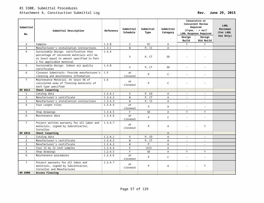
01 3300, Submittal ProceduresAttachment A, Construction Submittal Log Rev. June 29, 2015
Submittal No. Submittal Description Reference Submittal
ScheduleSubmittal
TypeSubmittal Category
Consecutive or Concurrent Review Required (Y=yes, - = no)?
LANL Response Required
LANL Reviewer
(For LANL Use Only)Design
BuildDesign Bid
Build2 Leakage, pressure drop, maximum operating [pressure]
[velocity], and maximum back pressure data1.2.A.1 Z OT A Y Y PE
3 UL ratings, dynamic ratings, and fire/smoke rating data. 1.2.A.2 Z OT A Y Y PE4 Damper pressure drop ratings based on tests and
procedures1.2.A.3 Z OT A Y Y PE
5 Shop drawings 1.2.B F D A - -6 Damper schedule 1.2.C W ML A Y Y PE7 Installation instructions 1.2.D W II A - -8 CoCs 1.2.E W CT A Y Y PE9 Welder certs 1.2.F F CT A Y Y PE10 LEED submittal 1.2.G X P SD Y Y PE
23 3400 HVAC FansProduct data for each type of product 1.4.A. X OT A - -
1 Include rated capacities, furnished specialties, and accessories for each fan
1.4.A.1 X OT A Y - PE
2 Certified fan performance curves with system operating conditions indicated
1.4.A.2 X PD A Y Y PE
3 Certified fan sound-power ratings 1.4.A.3 X CT A Y Y PE4 Motor ratings and electrical characteristics, plus motor
and electrical accessories1.4.A.4 X OT A - -
5 Material thickness and finishes, including color charts 1.4.A.5 X ML A - -6 Dampers, including housings, linkages, and operators 1.4.A.6 X OT A Y Y PE
Shop Drawings to include: 1.4.B. F D A - -7 Plans, elevations, sections, and attachment details 1.4.B.1 F D A Y - PE8 Details of equipment assemblies. Indicate dimensions,
weights, loads, required clearances, method of field assembly, components, and location and size of each field connection
1.4.B.2
F D A Y Y PE
9 Diagrams for power, signal, and control wiring 1.4.B.3 F ED A - -10 Manufacturer's Installation, Operation and Maintenance
(IOM) Instructions: Submit fan manufacturer’s IOM instructions. Include instructions for rigging, lifting, bearing lubrication, motor and drive replacement and wiring diagrams
1.4.C
at closeout OM, II C - -
11 Manufacturer's Certificate: Certify products meet or exceed specified requirements
1.4.D Y CT A Y Y PE
Delegated Design Submittal 1.4.E Z O, OT DD Y - PE12 Vibration Isolation Base Details 1.4.E.1 Z II A Y Y PE13 Design Calculations 1.4.E.2 Z CA A Y - PE
23 3816 Fume HoodsProduct data 1.5.B X P A Y Y PE
1 Catalog or manufacturer’s data 1.5.B.1 X P A Y Y PE2 Materials/parts list 1.5.B.2 W P A - -
Shop drawings 1.5.C F D A - -
Page 57 of 83
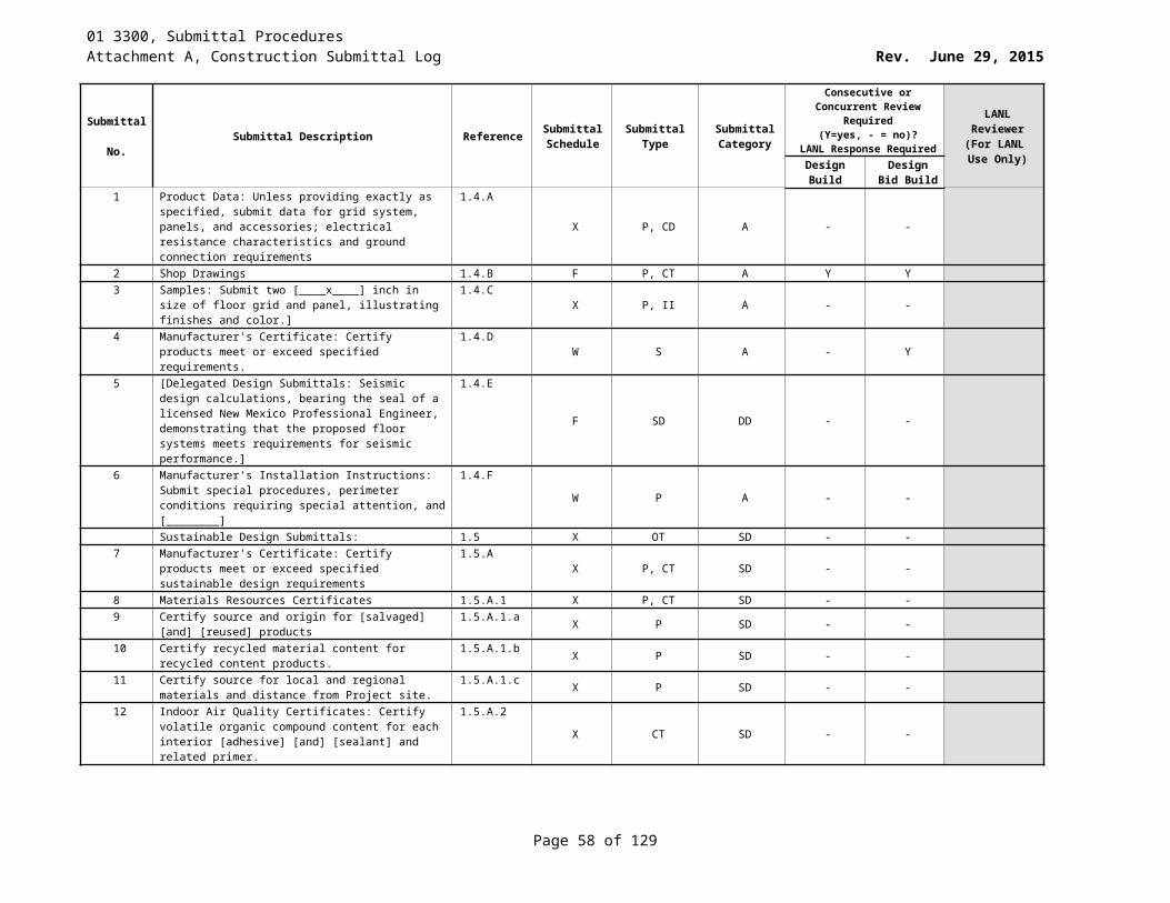
01 3300, Submittal ProceduresAttachment A, Construction Submittal Log Rev. June 29, 2015
Submittal No. Submittal Description Reference Submittal
ScheduleSubmittal
TypeSubmittal Category
Consecutive or Concurrent Review Required (Y=yes, - = no)?
LANL Response Required
LANL Reviewer
(For LANL Use Only)Design
BuildDesign Bid
Build3 Shop drawings indicating component dimensions,
tolerances, equipment locations, large scale plans, elevations, ends, cross sections, mechanical/electrical rough-in and anchor placement dimensions, clearances for maintenance and operation, size and location of field connections, construction details, utility requirements, service run spaces, and materials used
1.5.C.1
F D A Y Y PE
4 Wiring diagrams 1.5.C.2 W D A - -5 Samples (int lining, enclosure, work surfaces, other
prefinished equip, signs). Penetration portal sample with grommet [include only when specified].
1.5.DX S A Y Y PE
Test Reports and Certificates 1.5.E WKLY TR,CT A Y Y PE6 Certification (CoC or other equivalent document) 1.5.E.1 Y P A Y Y PE7 UL Standards for Safety listing 1.5.E.2 Y P A - -8 Test reports 1.5.E.3 WKLY TR A Y Y PE9 Certification 1.5.E.4 F CT A Y Y PE10 Test report 1.5.E.5 WKLY TR A Y Y PE
Manufacturer’s instructions 1.5.F W P A - -11 Manufacturer’s installation and assembly instructions 1.5.F.1 W P, II A - -12 Written instructions 1.5.F.2 W P A - -13 Submit in accordance with Sections 01 3300 and 01 7700 1.5.G.1 Closeout P C - -
23 4133 High Efficiency Particulate Filtration1 ASME AG-1, Section FC HEPA Filters 1.6.A - -2 Certification documentation 1.6.A.1 Y P-CT A Y Y PE3 Certified performance test results by the FTF 1.6.A.2 Y CT-TR A Y Y PE4 Certified performance test results by the manufacturer 1.6.A.3 Y CT-TR A Y Y PE5 QA plan (if not on IESL) 1.6.A.4 X, Z P A Y Y QA6 COC that is signed or otherwise authenticated and stating
specific information listed1.6.A.5 Y CT A Y Y PE
7 Statement indicating filters meet several specific requirements
1.6.A.6 Y CT A Y Y PE
8 Warranty documentation 1.6.A.7 Y WA A - -9 ASME AG-1, Section FK Special HEPA Filters 1.6.B - -10 Certification documentation 1.6.B.1 Y P A Y Y PE11 Certified performance test results by the FTF 1.6.B.2 Y CT-TR A Y Y PE12 Certified performance test results by the manufacturer 1.6.B.3 Y CT-TR A Y Y PE13 QA plan identifying procurement, fabrication, test &
inspection, material traceability and non-conformity controls for approval (if not on IESL)
1.6.B.4X, Z P A Y Y QA
14 CoC that is signed or otherwise authenticated and stating specific information listed
1.6.B.5 Y CT A Y Y PE
15 Statement indicating that filters meet several specific requirements
1.6.B.6 Y CT A Y Y PE
16 Warranty Documentation 1.6.B.7 Y WA A - -17 Auxiliary HEPA Filters 1.6.C - -
Page 58 of 83
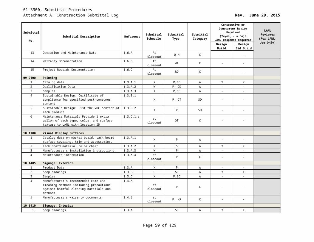
01 3300, Submittal ProceduresAttachment A, Construction Submittal Log Rev. June 29, 2015
Submittal No. Submittal Description Reference Submittal
ScheduleSubmittal
TypeSubmittal Category
Consecutive or Concurrent Review Required (Y=yes, - = no)?
LANL Response Required
LANL Reviewer
(For LANL Use Only)Design
BuildDesign Bid
Build18 CoC that is signed or otherwise authenticated by
responsible managers within the supplying organization and that certifies the conformance of end-items to several specific order requirements
1.6.C.1
Y CT A Y Y PE
19 Warranty Documentation 1.6.C.2 Y WA A - -23 6200 Packaged Compressor and Condenser Units
1 Product Data: For each air-cooled packaged compressor and condenser unit, include rated capacities, operating characteristics, furnished specialties and accessories.
1.4.AX P A Y Y PE
2 Shop Drawings: Indicate components, assembly, dimensions, weights and loading, required clearances, location and size of field connections, electrical requirements, and wiring diagrams for power, signal and control wiring. Include schematic layouts showing condenser, refrigeration compressors, cooling coils, refrigerant piping and accessories required for complete system. Include plans, elevations, sections, details, and attachments to other work
1.4.B
F SD, P A Y Y PE
3 Manufacturer's Installation Instructions1.4.C W II A - -
4 Operation and Maintenance Data: Submit instructions for lubrication, filter replacement, motor and drive replacement, spare parts lists, and wiring diagrams
1.4.Dat closeout SP, D, O M C - -
5 NOTE: Provide LEED submittals only if the project is pursuing LEED certification.
1.4 - -
6 LEED Submittals: 1.4.EX P SD Y Y PE
7 Product Data for Prerequisite EA 2: Documentation indicating that units comply with applicable requirements in ASHRAE/IESNA 90.1
1.4.E.1X P SD Y Y PE
8 Product Data for Credit EA 4: Documentation indicating that compressor and condenser units and refrigerants comply
1.4.E.2X P SD Y Y PE
9 Delegated-Design Submittal: For vibration isolation and seismic restraints indicated to comply with performance requirements and design criteria, including analysis data signed and sealed by the NM licensed professional engineer responsible for their preparation
1.4.F
F P DD Y Y PE
10 Vibration Isolation Base Details: Installation details including anchorages and attachments to structure and to supported equipment. Include auxiliary motor slides and rails and equipment mounting frames
1.4.F.1
F II, P DD Y Y PE
11 Design Calculations: Calculate requirements for selecting vibration isolators and seismic restraints, and for designing vibration isolation bases
1.4.F.2F CA DD Y - PE
23 6509 Induced-Draft Cooling Towers - -Steel1 Catalog data 1.3.A.1 X CD, P A Y Y PE2 Certifications 1.3.A.2 F CT, P A Y Y PE
Page 59 of 83
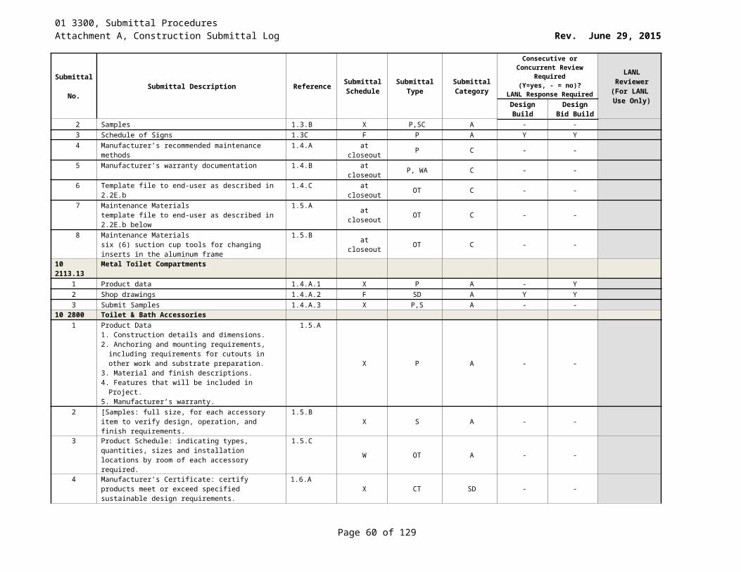
01 3300, Submittal ProceduresAttachment A, Construction Submittal Log Rev. June 29, 2015
Submittal No. Submittal Description Reference Submittal
ScheduleSubmittal
TypeSubmittal Category
Consecutive or Concurrent Review Required (Y=yes, - = no)?
LANL Response Required
LANL Reviewer
(For LANL Use Only)Design
BuildDesign Bid
Build3 Installation instructions 1.3.A.3 W II A - -4 Performance curves 1.3.A.4 X PD, P A Y Y PE5 Operations and maintenance data. 1.3.A.5 at closeout OM, P C - -6 Warranties 1.3.A.6 at closeout WA, P C - -7 Shop drawings 1.3.A.7 F SD A - -
23 6511 Induced-Draft Cooling Towers --Fiberglass1 Catalog data 1.3.A.1 X CD, P A Y Y PE2 Certifications 1.3.A.2 F CT, P A Y Y PE3 Installation instructions 1.3.A.3 W II A - -4 Performance curves 1.3.A.4 X PD, P A Y Y PE5 Operations and maintenance data 1.3.A.5 at closeout OM, P C - -6 Warranties 1.3.A.6 at closeout WA, P C - -7 Shop drawings 1.3.A.7 F SD A - -
23 7300 Indoor Central-Station Air Handling Units1 Shop Drawings 1.4.A F SD A Y Y PE2 Product Data, submit the following: 1.4.B. X CD A - -3 Published Literature 1.4.B.1 X P A Y Y PE4 Filters 1.4.B.2 X P A Y Y PE5 Fans 1.4.B.3 X P A Y Y PE6 Coils 1.4.B.4 X P A Y Y PE7 Dampers 1.4.B.5 X P A Y Y PE8 Sound Power Level Data 1.4.B.6 X P A Y Y PE9 Electrical Requirements 1.4.B.7 X D A Y Y PE10 LEED Submittal: 1.4.C X P SD - -11 Product Data for Prerequisite EQ 1 1.4.C.1 X P SD Y Y PE12 Product Data for Prerequisite EQ 2 1.4.C.2 X P SD Y Y PE13 Manufacturer’s Installation Instructions 1.4.D W II A - -14 Operation and Maintenance Data 1.4.E at closeout II, SP, D, WA C - -15 Delegated-Design Submittal 1.4.F F P DD Y - PE16 Vibration Isolation Base Details 1.4.F.1 F II DD Y Y PE17 Design Calculations 1.4.F.2 F CA DD Y - PE
23 7413 Packaged, Outdoor, Central Station1 Shop Drawings, the following: 1.2.B F SD A Y Y PE2 Assembly drawings showing unit dimensions, weight
loading, required clearances, construction details, field connection details, and electrical characteristics and connection requirements.
1.2.B.1
F D A Y Y PE
3 Product data 1.2.C X P A - -4 Published Literature indicating cooling and heating
capacities, ratings, gages, finishes of materials, electrical characteristics and connection requirements, controls, and accessories.
1.2.C.1
X P A Y Y PE
5 Data for filter media, filter performance data, filter assembly, and filter frames.
1.2.C.2 X P A Y Y PE
6 Performance and fan curves with specified operating point plotted, power, RPM.
1.2.C.3 X P, D, PD A Y Y PE
Page 60 of 83
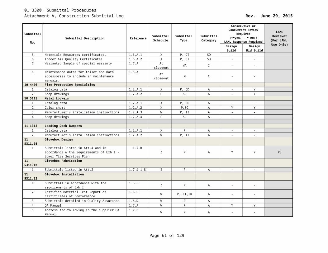
01 3300, Submittal ProceduresAttachment A, Construction Submittal Log Rev. June 29, 2015
Submittal No. Submittal Description Reference Submittal
ScheduleSubmittal
TypeSubmittal Category
Consecutive or Concurrent Review Required (Y=yes, - = no)?
LANL Response Required
LANL Reviewer
(For LANL Use Only)Design
BuildDesign Bid
Build7 Sound Power Level Data: Fan outlet and casing radiation
at rated capacity.1.2.C.4 W P A Y Y PE
8 Dampers: Include leakage, pressure drop, and sample calibration curves. Indicate materials, construction, dimensions, and installation details.
1.2.C.5W P A Y Y PE
9 Electrical requirements 1.2.C.6 W P A Y Y PE10 Test Reports Submit results of factory test at [time of unit
shipment]1.2.D S TR A Y Y PE
11 Manufacturer's Installation Instructions 1.2.E W P-II A - -12 Manufacturer's Certificate 1.2.F W CT A Y Y PE13 Manufacturer’s Field Reports: 1.2.G WKLY P A Y Y PE14 Operations and maintenance data 1.2.H at closeout P, OM C - -
23 8123 Computer-Room Air-Conditioners1 Product data: For each type of product indicated. Include
rated capacities, operating characteristics, electrical characteristics, and furnished specialties and accessories
1.4.AX OT A Y Y PE
2 Shop drawings: For computer-room air conditioners. Include plans, elevations, sections, details, and attachments to other work
1.4.BF D A - -
3 Detail equipment assemblies and indicate dimensions, weights, loads, required clearances, method of field assembly, components, and location and size of each field connection
1.4.B.1
F OT A Y Y PE
4 Wiring Diagrams: For power, signal, and control wiring 1.4.B.2 W ED A - -5 Manufacturer's Installation Instructions: Submit
procedures for rigging and making service connections1.4.C W II A - -
6 Operation and Maintenance Data: Submit installation instructions, start-up instructions, operating and maintenance instructions, parts lists, controls, and accessories
1.4.D
at closeout OM C - -
7 Manufacturer's Certificate: Certify products meet or exceed specified requirements
1.4.E Y CT A Y Y PE
8 LEED Submittals 1.4.F S P SD Y Y PE9 Product Data for Credit EA 4: Documentation indicating
that equipment and refrigerants comply1.4.F.1 S P SD Y Y PE
10 Product Data for Prerequisite IEQ 1: Documentation indicating that units comply with ASHRAE 62.1
1.4.F.2 S P SD Y Y PE
23 8239 Unit Heaters1 Product Data: for each type and size of unit heater
indicated1.3.A X P A - -
2 Shop Drawings: Detail equipment assemblies and indicate dimensions, weights, loads, required clearances, method of field assembly, components, and location and size of each field connection
1.3.B
F SD A - -
3 Plans, elevations, sections, and details 1.3.B.1 F D A - -
Page 61 of 83
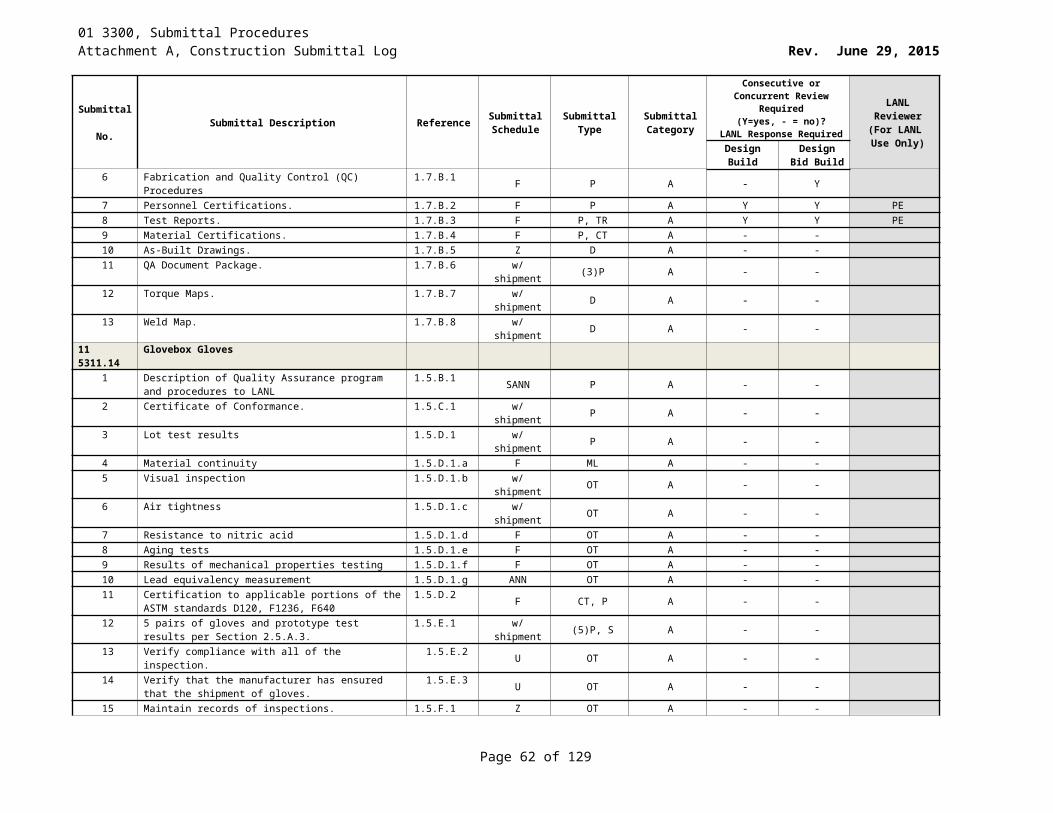
01 3300, Submittal ProceduresAttachment A, Construction Submittal Log Rev. June 29, 2015
Submittal No. Submittal Description Reference Submittal
ScheduleSubmittal
TypeSubmittal Category
Consecutive or Concurrent Review Required (Y=yes, - = no)?
LANL Response Required
LANL Reviewer
(For LANL Use Only)Design
BuildDesign Bid
Build4 Detail equipment assemblies and indicate dimensions,
weights, loads, required clearances, method of field assembly
1.3.B.2F P A Y Y PE
5 Location and size of each field connection 1.3.B.3 F P A - -6 Wiring Diagrams: Power, signal, and control wiring as
applicable1.3.B.4 F ED A - -
7 Equipment schedules to include rated capacities, furnished specialties, and accessories
1.3.B.5 F P A Y Y PE
8 Manufacturer's Installation Instructions 1.3.C F II A - -9 Warranty: Provide documentation of [Five] [Ten] [_____]
year warranty1.3.D at closeout WA A - -
10 Unit Heater Labeling: Certified and labeled by testing agency acceptable to authorities having jurisdiction. [UL, AGA, ASHRAE, CSA]
1.3.EF CT, O A - -
11 Test Reports: For each type of [electric,] [gas-fired] [hot water] unit heater. [Include factory test reports]
1.3.F W TR A Y Y PE
12 Operation and maintenance data: Include emergency, operation, and maintenance manuals
1.3.G at closeout O, M C - -
25 5000 Integrated Automated Facility Controls1 BAS system manufacturer and subcontract information 1.3.A.1 With Bid P A - -2 Submittals 1.3.A.2 W P, D A - -3 Shop drawings shall be provided that show detailed
communications 1.3.A.2.a F P, D,EM A - -
4 Electrical Ladder Diagrams 1.3.A.2.a.i F D A - -5 The sequence of operation 1.3.A.2.a.ii W P A - -6 A complete material listing shall be included 1.3.A.2.a.iii X P A - -7 Catalog data sheets shall be provided for each different
piece of equipment 1.3.A.2.b X P A - -
8 Point verification and sensor calibration forms for all points and sensors that are installed as part of the BAS.
1.3.A.2.c Y P A - -
9 All graphic slides proposed for use 1.3.A.2.d Z P A - -10 Software development parameters 1.3.A.2.e Z P A - -11 Report templates 1.3.A.2.e.i Z EM A - -12 Blank forms for completion of password information by the
LANL STR. 1.3.A.2.e.ii Z OT A - -
13 Blank schedule forms for each air-handling unit for completion by the LANL STR.
1.3.A.2.e.iii Z P A - -
14 Provide detailed operation sequences 1.3.A.2.f W P A - -
26 0519 Low Voltage Electrical Power Conductors and Cables1 Certification of the Subcontractor’s tool and instrument
calibration program1.4.A W CT A Y -
2 Field test records on tool and instrument calibration, termination torque records, cable pulling, and Field Quality Control inspection reports and tests results.
1.5.A.1WKLY TR C Y Y
Page 62 of 83
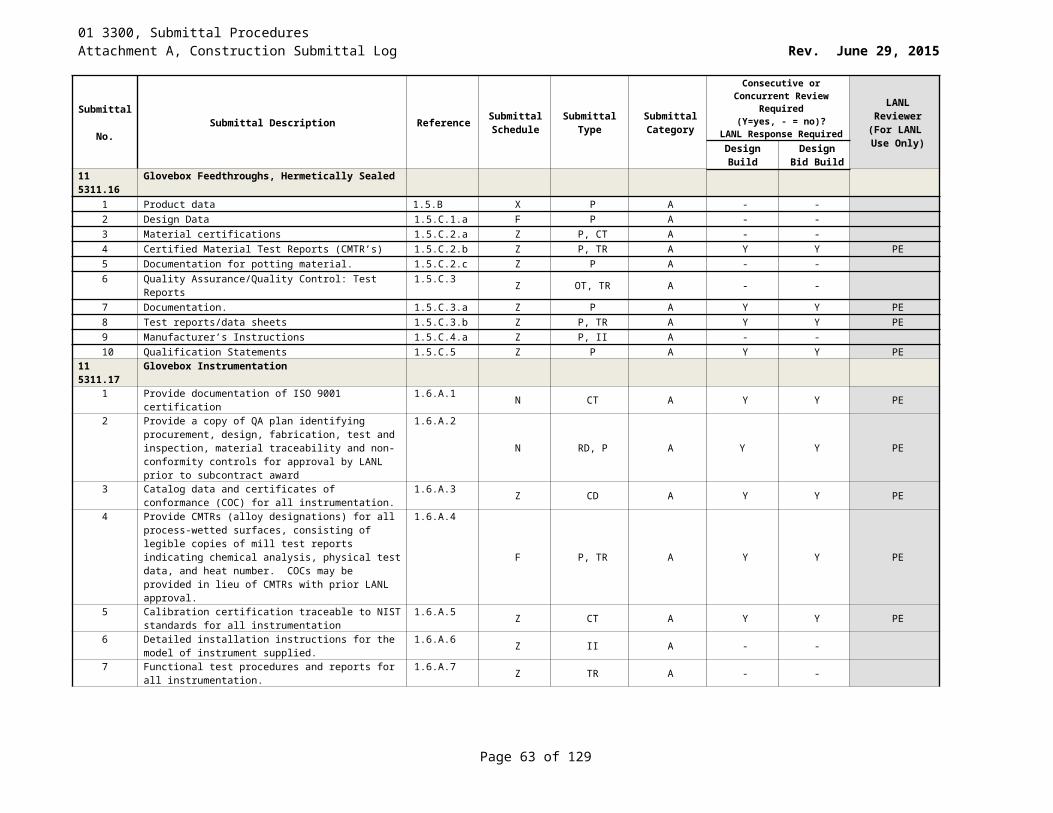
01 3300, Submittal ProceduresAttachment A, Construction Submittal Log Rev. June 29, 2015
Submittal No. Submittal Description Reference Submittal
ScheduleSubmittal
TypeSubmittal Category
Consecutive or Concurrent Review Required (Y=yes, - = no)?
LANL Response Required
LANL Reviewer
(For LANL Use Only)Design
BuildDesign Bid
Build26 0526 Grounding and Bonding for Electrical Systems
1 Catalog Data for grounding conductors 1.3.A.1 X CD A Y Y PE2 Shop Drawings: for signal reference grid fabrication and
installation.1.3.A.2 U SD A Y Y PE
3 Project Record Documents: to include specified certifications and field test reports of installed grounding systems
1.3.A.3Z RD A Y Y PE
26 0529 Hangers and Supports for Electrical Systems1 Catalog Data: for each type of product specified. 1.4.A.1 X CD, P A Y Y
26 0533 Raceway and Boxes for Electrical Systems1 Catalog Data: describing floor boxes. 1.2.A.1 Z CD, P A Y Y2 Catalog Data: describing surface metal raceway. 1.2.A.2 Z CD, P A Y Y3 Catalog Data: describing wireway. 1.2.A.3 Z CD, P A Y Y
26 0536 Cable Trays for Electrical Systems1 Catalog Data: manufacturer's data 1.3.A.1.a X CD A Y Y PE2 Manufacturer's data on smoke seal and fire stop products 1.3.A.1.b X P A Y Y3 Test Reports: results of tests performed or witnessed 1.3.A.2 WKLY TR A Y Y4 Shop Drawings: Detail fabrication and installation of cable
tray1.3.A.3 F SD A Y Y
5 Installation Instructions: Indicate application conditions and limitations of use
1.3.A.4 W II A Y Y
6 Certification Submit certification and backup information that cable tray systems with Ip greater than 1.0 can perform required functions after a design earthquake as specified in "SERVICE CONDITIONS" below. Refer to Section 26 0548 – Vibration and Seismic Controls for Electrical Systems
1.3.A.5
W CT A Y Y
26 0548 Vibration and Seismic Controls for Electrical Systems1 Catalog Data: Submit catalog data for each type of
product specified. Include information substantiating equivalent corrosion resistance to zinc coated steel of alternative treatment, finish, or inherent material characteristic
1.4.A
X CD, P A Y Y
2 Material List: Submit schedule showing manufacturer's figure number, size, spacing, features, and application for each required type of hanger, support, sleeve, seal, vibration isolator, and fastener to be used
1.4.B
F ML A Y Y
Test reports: 1.4.C3 Pre-set Concrete Anchors 1.4.C.2 X P A Y Y4 Vibration Isolators 1.4.C.3 X P A Y Y
Shop Drawings: Submit shop drawings showing details of fabricated hangers, vibration isolators, supports, and seismic control of the electrical nonstructural components listed below
1.4.D
5 Battery racks and battery cabinets 1.4.D.1 F SD A Y Y6 Cable trays 1.4.D.2 F SD A Y Y7 Enclosed bus assemblies 1.4.D.3 F SD A Y Y
Page 63 of 83
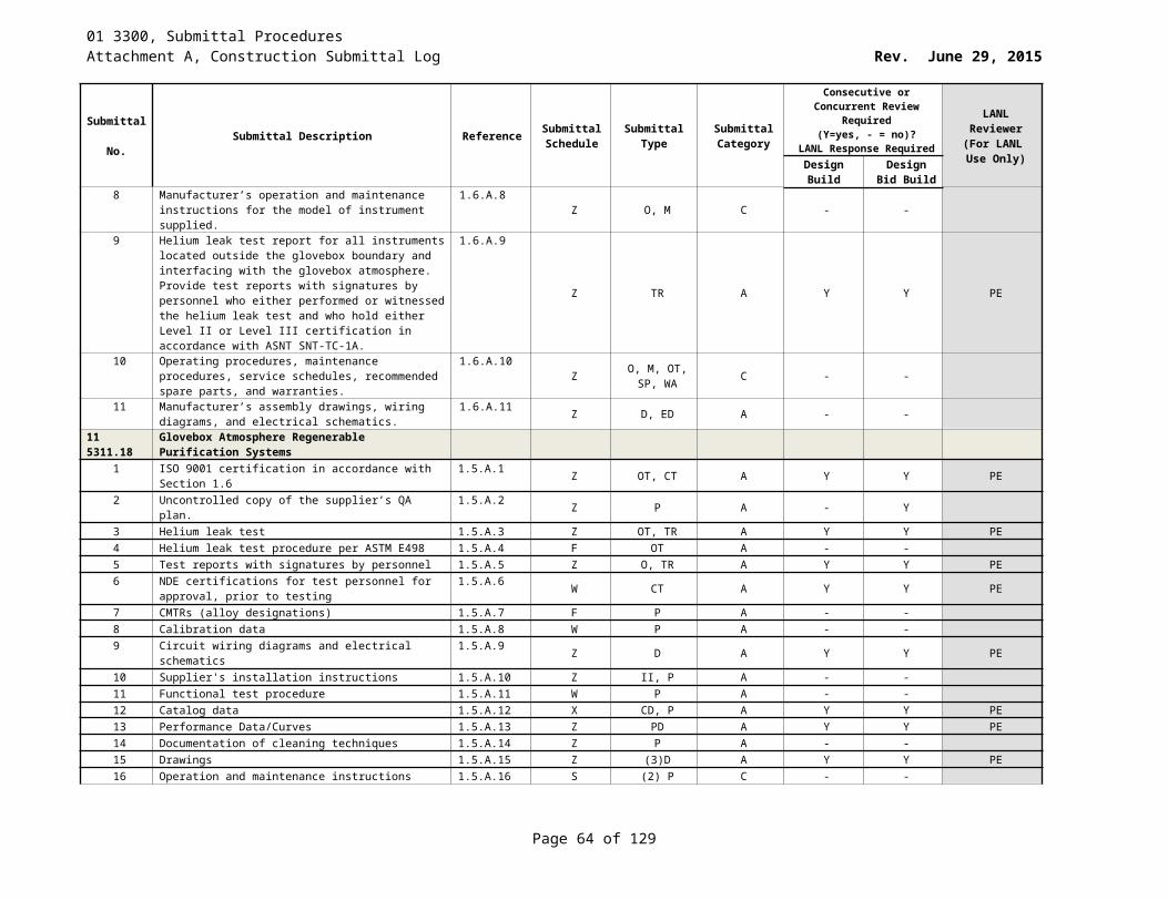
01 3300, Submittal ProceduresAttachment A, Construction Submittal Log Rev. June 29, 2015
Submittal No. Submittal Description Reference Submittal
ScheduleSubmittal
TypeSubmittal Category
Consecutive or Concurrent Review Required (Y=yes, - = no)?
LANL Response Required
LANL Reviewer
(For LANL Use Only)Design
BuildDesign Bid
Build8 Transformers 1.4.D.4 F SD A Y Y
Component Certifications: 1.4.E9 Unit substation [SUS-A] 1.4.E.1 F CT A Y Y10 Transformers [XFMR-A, XFMR-3] 1.4.E.2 F CT A Y Y11 Switchgear [SWGR-B] 1.4.E.3 F CT A Y Y12 Switchboard [SWBD-E] 1.4.E.4 F CT A Y Y13 Panelboards [EP-A, EP-1] 1.4.E.5 F CT A Y Y14 Enclosed circuit breakers and safety switches [CBE-G,
CDD-E]1.4.E.6 F CT A Y Y
15 Motor control center [MCC-D] 1.4.E.7 F CT A Y Y16 Variable frequency motor controllers [VFD-F, VFD-H] 1.4.E.8 F CT A Y Y17 Engine-generator [GDE-A] 1.4.E.9 F CT A Y Y18 Uninterruptible power supply [UPS-D] 1.4.E.10 F CT A Y Y
26 0553 Identification for Electrical Systems1 Catalog Data: for each product. 1.3.A.1 X CD, P A Y Y2 Electrical identification schedule 1.3.A.2 W P A Y Y3 Samples: [two] samples of each type of printed
identification products applicable to project.1.3.A.3.a X (2)S A Y Y
4 Samples: [two] nameplates illustrating materials and engraving quality
1.3.A.3.b X (2)S A Y Y
5 Manufacturer's Installation Instructions 1.3.A.4 W II A Y Y26 0700 Induction Motors – 500HP and Smaller
1 Catalog Data for each motor furnished loose 1.3.A.1 X CD, P A Y Y2 Motor selection calculations 1.3.A.2 X P, CA A Y Y3 Certification: motors can perform required functions after
a design earthquake as specified in "SERVICE CONDITIONS"
1.3.A.3X CT, P A Y Y
4 Certification: motors meet specified performance, efficiency, and selection requirements.
1.3.A.4 X CT, P A Y Y
5 Test Reports 1.3.A.5 W TR, P A Y Y6 Installation Instructions 1.3.A.6 W P A Y Y7 Operation and Maintenance Data 1.3.A.7 at closeout P C Y Y8 Operation data including instructions for safe operating
procedures.1.3.A.7.a Y P A Y Y
9 Maintenance Data including assembly drawings, bearing data with replacements sizes, and lubrication instructions.
1.3.A.7.b at closeout P, D C Y Y
26 0813 Electrical Acceptance Testing1 Certifications: name and qualifications of the ETA 1.5.A.1 W CT A Y Y PE2 Certifications: quality assurance program of the ETA 1.5.A.2 W CT A Y Y PE3 Certifications: instrument calibration program of the ETA 1.5.A.3 W CT A Y Y PE4 Certifications: electrical safety program of the ETA 1.5.A.4 W CT A Y Y PE5 Certifications: name and qualifications of the lead
engineer or engineering technician performing the required testing services.
1.5.A.5W CT A Y Y PE
Page 64 of 83
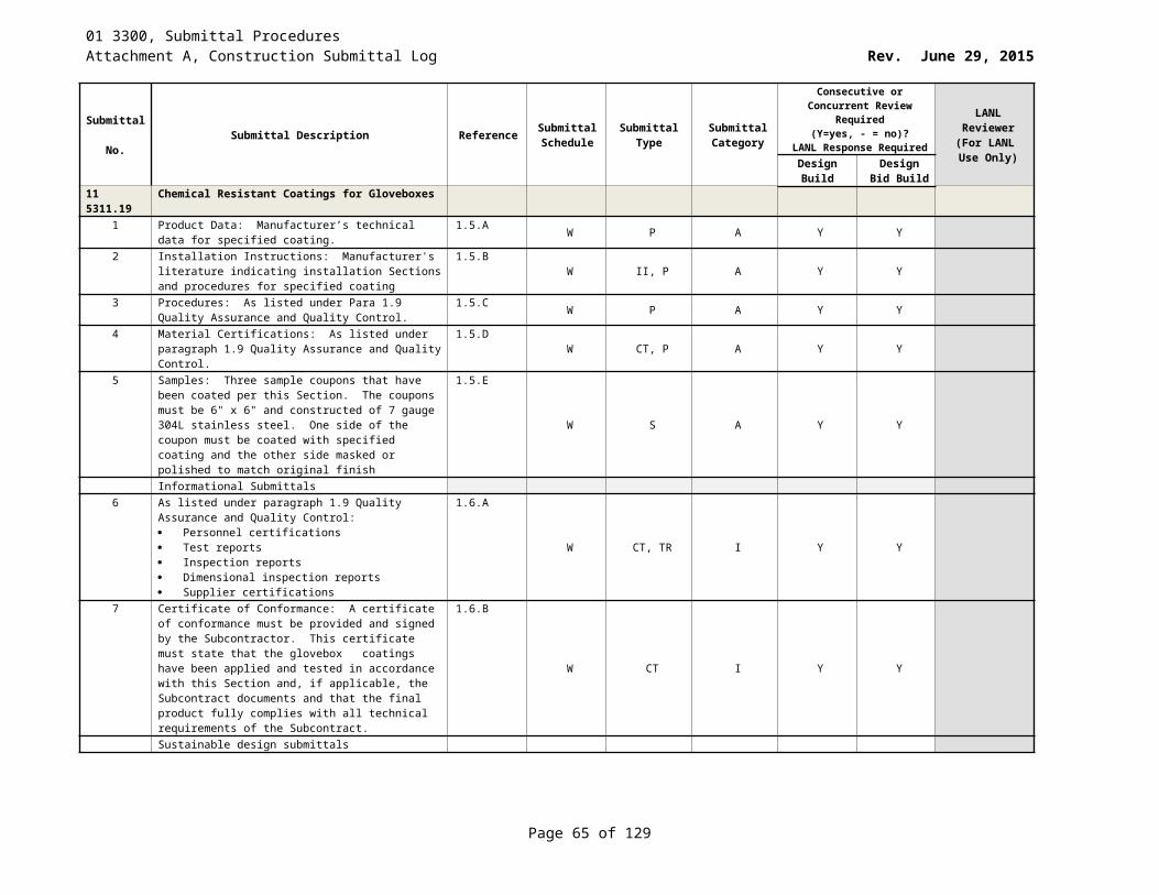
01 3300, Submittal ProceduresAttachment A, Construction Submittal Log Rev. June 29, 2015
Submittal No. Submittal Description Reference Submittal
ScheduleSubmittal
TypeSubmittal Category
Consecutive or Concurrent Review Required (Y=yes, - = no)?
LANL Response Required
LANL Reviewer
(For LANL Use Only)Design
BuildDesign Bid
Build6 Test Plans: acceptance and system functions test plan for
each item of equipment or system to be field tested at least 45 days prior to planned testing date.
1.5.A.6U P A Y Y PE
7 Test Reports: certified copies of inspection reports, test reports, and system function tests.
1.5.A.7 Z O TR A Y Y PE
Calculations: certified copies of power system studies listed below.
1.5.A.8 Z CA A Y Y PE
8 Final short circuit study 1.5.A.8.a Z CA A Y Y PE9 Final coordination study 1.5.A.8.b Z CA A Y Y PE10 Arc-flash hazard analysis 1.5.A.8.c Z CA A Y Y PE11 Load flow study 1.5.A.8.d Z CA A Y Y PE12 Stability study 1.5.A.8.e Z CA A Y Y PE13 Harmonic analysis 1.5.A.8.f Z CA A Y Y PE
26 2213 Low Voltage Distribution Transformers1 Catalog Data. 1.3.B X P, CD A Y Y PE2 Certifications signed by manufacturers 1.3.C X CT A Y Y3 Operation and maintenance instructions 1.3.D At Closeout P C Y Y
26 2300 Low Voltage Switchgear1 Catalog data showing compliance with specified
requirements1.2.B X P, CD A Y Y
2 Certification and backup information that low-voltage switchgear can perform required functions after a design earthquake as specified in "SERVICE CONDITIONS"
1.2.CX P, CT A Y Y
3 Certification by manufacturer’s field technical representative that the subcontractor has installed, adjusted, and tested the low-voltage switchgear according to the manufacturer’s recommendations.
1.2.D
Y P, CT A Y Y
4 Installation instructions indicating application conditions and limitations of use stipulated by Product testing agency specified under Quality Assurance. Include instructions for storage, handling, protection, examination, installation, and starting of Product, including equipment anchoring requirements to meet the seismic conditions specified in "SERVICE CONDITIONS”.
1.2.E
W P, II A Y Y
5 Operations and Maintenance Instructions including step-by-step inspection and maintenance test procedures and a listing of recommended spare parts. Include instructions for testing circuit breakers. [Include a test procedure for the modified differential ground fault system using high current injection equipment
1.2.F
At Closeout D C Y Y
6 Performance Data/Curves including time-current curves for each circuit breaker
1.2.G Y PD A Y Y
Page 65 of 83

01 3300, Submittal ProceduresAttachment A, Construction Submittal Log Rev. June 29, 2015
Submittal No. Submittal Description Reference Submittal
ScheduleSubmittal
TypeSubmittal Category
Consecutive or Concurrent Review Required (Y=yes, - = no)?
LANL Response Required
LANL Reviewer
(For LANL Use Only)Design
BuildDesign Bid
Build7 Shop drawings with front views and plan view of the
assembly, single line or three line diagrams, nameplate schedule, component lists, conduit space locations within the assembly, busway entry location and details, assembly ratings , major component ratings , cable terminal sizes, shipping splits, enclosure type with details for types other than NEMA type 1, bus configuration and current ratings, features, characteristics , ratings, and factory settings of individual protective devices and auxiliary components, key interlock scheme drawing and sequence of operations, connection details between close-coupled assemblies , composite front view and plan of close coupled assemblies, description of the main-tie-main automatic throw-over system to include components and operating sequences
1.2.H
W D A Y Y
8 Certified production test reports. 1.2.I W P, CT,TR A Y Y9 Letter indicating that manufacturer will issue a one year
commercial warranty 1.2.J X P A Y Y
10 Wiring Diagrams including detailed schematic wiring diagrams including device identifications and numbered terminals for power, control, communications and instrumentation systems, and differentiating between manufacturer-installed and field-installed wiring. [Include a wiring diagram of the modified differential ground fault system.]
1.2.K
W P A Y Y
26 2413 Switchboards1 Calculations 1.2.A.1 W P, CA A Y Y2 Catalog Data: describing each type 1.2.A.2 X P, CD A Y Y3 Certification: certification and backup information: certified
by the manufacturer to withstand the total lateral seismic force; certification based on shake table testing or experience data and required response spectra
1.2.A.3
W P, CT A Y Y
4 Certification: by manufacturer’s field technical representative
1.2.A.4 W P, CT A Y Y
5 Installation Instructions: Indicate application conditions and limitations of use
1.2.A.5 W P, II A Y Y
6 Operation and maintenance instructions 1.2.A.6 At Closeout P, OM C Y Y7 Time-current curves for each circuit breaker 1.2.A.7 W P A Y Y8 Shop drawings for each switchboard Including: front, side,
and plan view of the switchboards, single line or three line diagrams, nameplate schedule, component lists, conduit entry locations, busway entry locations and details, switchboard ratings, major component ratings including voltage, current, and interrupting, cable terminal sizes and types, shipping splits, enclosure type with details for types other than NEMA type 1, bus configuration and current ratings, features, characteristics, ratings, and factory settings, key interlock scheme drawing and sequence of operations
1.2.A.8
F SD A Y Y
Page 66 of 83
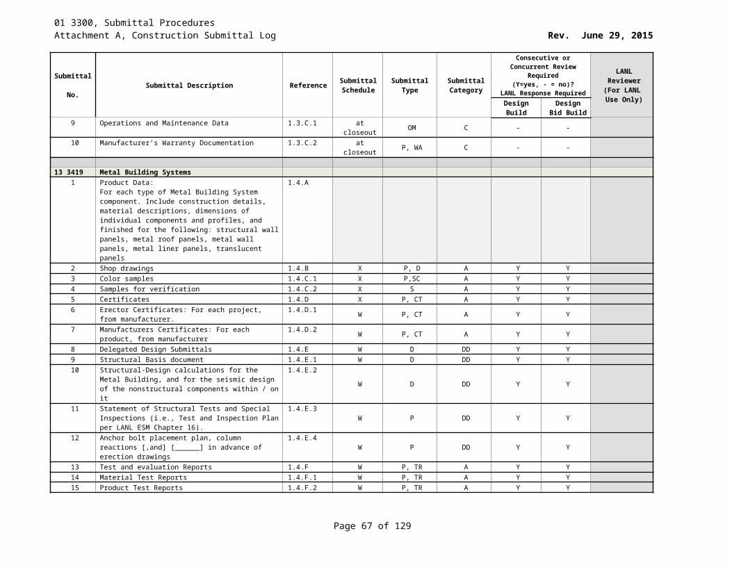
01 3300, Submittal ProceduresAttachment A, Construction Submittal Log Rev. June 29, 2015
Submittal No. Submittal Description Reference Submittal
ScheduleSubmittal
TypeSubmittal Category
Consecutive or Concurrent Review Required (Y=yes, - = no)?
LANL Response Required
LANL Reviewer
(For LANL Use Only)Design
BuildDesign Bid
Build9 Results of factory production tests 1.2.A.9 Z P A Y Y10 Warranty: Letter indicating that manufacturer will issue a
one year commercial warranty against defects in material or workmanship when the LANL has received inspected and accepted the equipment
1.2.A.10
X P, WA A Y Y
11 Detailed schematic wiring diagrams 1.2.A.11 W ED A Y Y26 2416 Panelboards
1 Catalog Data 1.2.A.1 X CD A Y Y PE2 Certification including Enclosure type with details for
types, bus configuration and current ratings, short-circuit current rating of panelboard, features, characteristics, ratings, and factory settings
1.2.A.2
X CT A Y Y PE
3 Shop drawings for each panelboard that includes enclosure type with details for types other than NEMA Type 1; bus configuration and current ratings; short-circuit current rating of panelboard; features, characteristics, ratings, and factory settings of individual protective devices and auxiliary components
1.2.A.3
X SD A Y Y PE
4 Detailed schematic wiring diagrams 1.2.A.4 X ED A Y Y PE5 Installation Instructions 1.2.A.5 X II A Y Y PE6 Operation and Maintenance Instructions 1.2.A.6 Z OM C Y Y PE
26 2419 Motor Control Centers1 Catalog Data: manufacturer’s descriptive literature
describing each MCC. Include data substantiating that materials comply with specified requirements including a full description of the arc-resistant design features
1.2.A.1
Z P, CD A Y Y
2 Shop drawings for each MCC 1.2.A.2 F SD A Y Y3 Wiring Diagrams 1.2.A.3 W D A Y Y4 MCC certification based on shake table testing or
experience data and required response spectra1.2.A.4.a Z P A Y Y
5 Certification: by manufacturer’s field technical representative that the subcontractor has installed, adjusted, and tested each MCC according to the manufacturer’s recommendations
1.2.A.5
W P, CT A Y Y
6 Installation Instructions 1.2.A.6 W P, II A Y Y7 Complete operation and maintenance instructions. Include
the manufacturer’s name, and brief description of equipment and its basic operational features.
1.2.A.7.aAt Closeout P, OM C Y Y
8 Test and Inspection Records: Records of inspections, tests, and adjustments performed under FIELD QUALITY CONTROL
1.2.A.8WKLY P, TR A Y Y
26 2500 Enclosed Bus Assemblies1 Catalog Data: manufacturer’s descriptive and technical
literature describing each type of enclosed bus assembly, fitting, bus plug-in device, and accessory item. Include data substantiating that materials and equipment comply with specified requirements
1.2.A.1
X P, CD A Y Y
Page 67 of 83
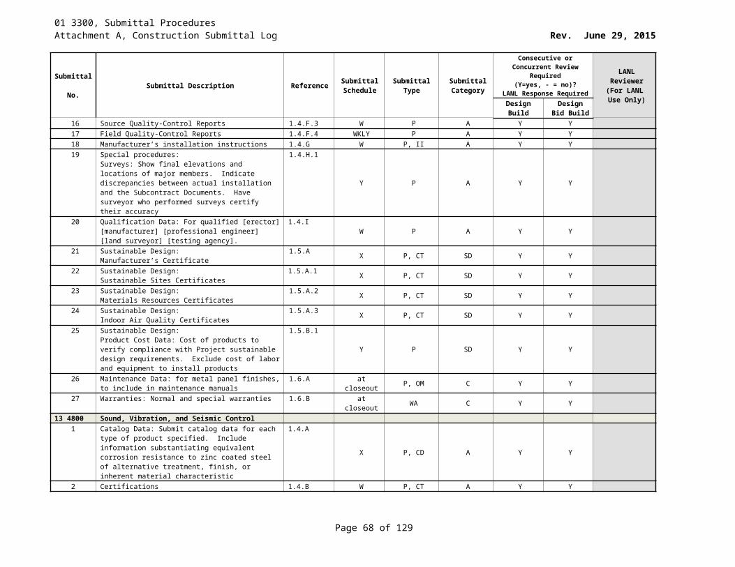
01 3300, Submittal ProceduresAttachment A, Construction Submittal Log Rev. June 29, 2015
Submittal No. Submittal Description Reference Submittal
ScheduleSubmittal
TypeSubmittal Category
Consecutive or Concurrent Review Required (Y=yes, - = no)?
LANL Response Required
LANL Reviewer
(For LANL Use Only)Design
BuildDesign Bid
Build2 Shop Drawings: For each type of assembly: Fabrication
and installation details for enclosed bus assemblies; show fittings, materials, fabrication, and installation methods; indicate required clearances; details including seismic-restraint details
1.2.A.2
F SD A Y Y
3 Wiring Diagrams: Submit power wiring diagram showing 1.2.A.3 W D A Y Y4 Coordination Drawings with Vertical and horizontal
enclosed bus-assembly runs, offsets, and transitions; Clearances for access; Vertical elevation; Support locations; Location of adjacent construction elements
1.2.A.4
W D A Y Y
5 Certification based on shake table testing or experience data and required response spectra
1.2.A.5 W P, CT A Y Y
6 Certification: certification and backup information that enclosed bus assemblies with Ip greater than 1.0 can perform required functions after a design earthquake as specified in “SERVICE CONDITIONS” below. Refer to Section 26 0548 – Vibration and Seismic Controls for Electrical Systems
1.2.A.5
F P, CT A Y Y
7 Certification: by manufacturer’s field technical representative
1.2.A.6 W P, CT A Y Y
8 Installation Instructions: Indicate application conditions and limitations of use
1.2.A.7 W P, II A Y Y
9 Operation and Maintenance Instructions: 1.2.A.8 At Closeout P, OM C Y Y10 Test reports 1.2.A.9 WKLY P, TR A Y Y
26 2713 Electricity Metering1 Catalog data and manufacturer's technical data 1.3.A.1 X P, CD A Y Y2 Installation instructions indicating application conditions
and limitations of use 1.3.A.2 W P A Y Y
3 Shop drawing of installation 1.3.A.3 F SD A Y Y4 Wiring diagram 1.3.A.4 W D A Y Y5 Operation and maintenance instructions 1.3.A.5 At Closeout P C Y Y
26 2726 Wiring Devices1 Catalog data 1.2.A.1 X P A Y Y2 Wiring Diagrams 1.2.A.2 W D A Y Y
26 2816 Enclosed Switches and Circuit Breakers1 Manufacturer's technical data for each 1.2.A.1 X P, CD A Y Y2 Installation Instructions: Indicate application conditions
and limitations of use 1.2.A.2 W P, II A Y Y
3 Certification Submit certification and backup information that safety switches and enclosed circuit breakers can perform required functions after a design earthquake as specified in "SERVICE CONDITIONS" below
1.2.A.3
F P, CT A Y Y
26 2913 Enclosed Controllers1 Catalog data: manufacturer's technical data 1.2.A.1 X CD A Y Y2 Installation instructions: Indicate application conditions
and limitations of use1.2.A.2 W P A Y Y
Page 68 of 83
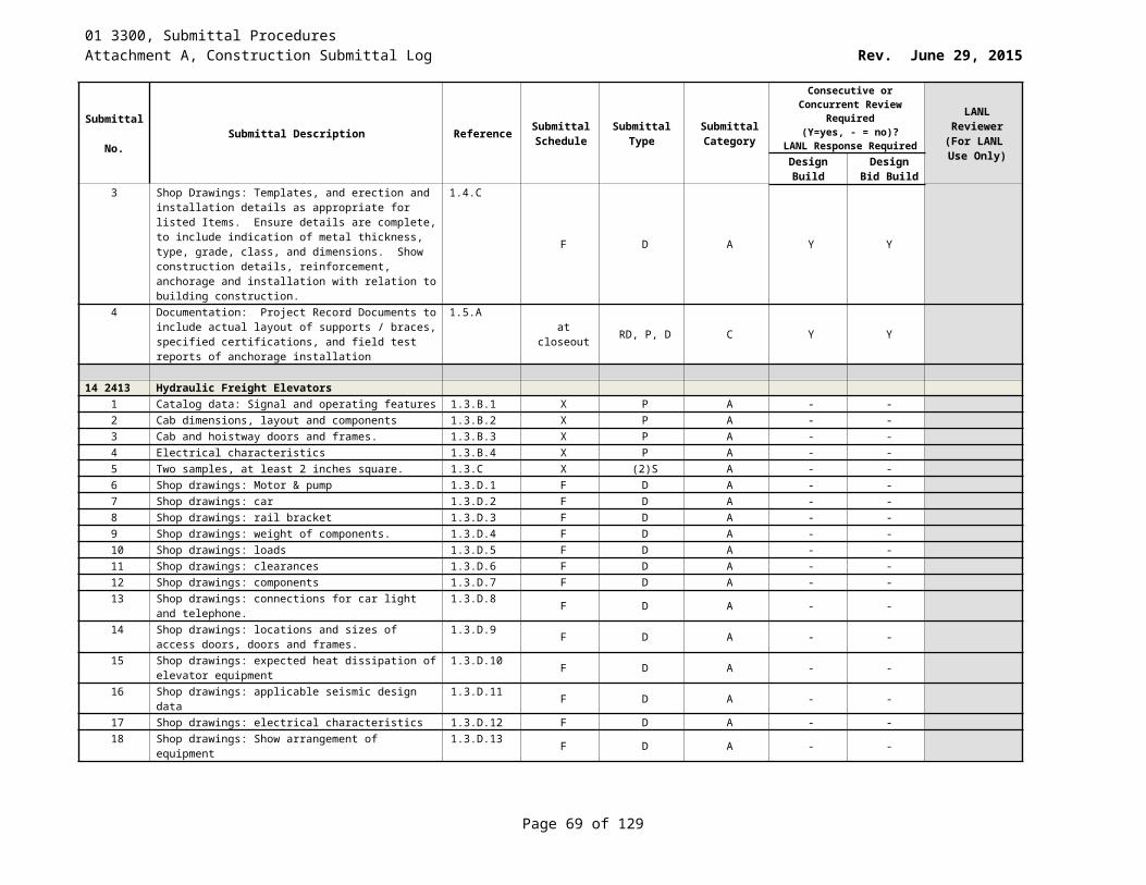
01 3300, Submittal ProceduresAttachment A, Construction Submittal Log Rev. June 29, 2015
Submittal No. Submittal Description Reference Submittal
ScheduleSubmittal
TypeSubmittal Category
Consecutive or Concurrent Review Required (Y=yes, - = no)?
LANL Response Required
LANL Reviewer
(For LANL Use Only)Design
BuildDesign Bid
Build3 Certification: Enclosed controller can perform required
functions after a design earthquake as specified in “SERVICE CONDITIONS”
1.2.A.3X CT A Y Y
4 Operation and maintenance instructions 1.2.A.4 At Closeout P, OM C Y Y5 Test and Inspection Records: Inspections, tests, and
adjustments performed under FIELD QUALITY CONTROL
1.2.A.5WKLY TR A Y Y
6 Wiring diagram 1.2.A.6 W D A Y Y26 2923 Variable Frequency Motor Controllers
1 Catalog Data: catalog data describing each type of AFC. 1.3.A.1 X P, CD A Y Y2 Calculations 1.3.A.2 F P, CA A Y Y3 Certification: that AFC can perform required functions
after design earthquake1.3.A.3 X CT A Y Y
4 Certification: that the subcontractor has installed, adjusted, and tested ea. AFC according to manufacture, recommendations
1.3.A.4X CT A Y Y
5 Shop Drawings: shop drawings for each AFC 1.3.A.5 F SD A Y Y6 Installation Instructions: Indicate application conditions
and limitations of use.1.3.A.6 W P, II A Y Y
7 Operation and Maintenance Instructions 1.3.A.7 At Closeout P, OM C Y Y8 Test Reports: results of required factory tests. 1.3.A.8 W P, TR A Y Y9 Warranty 1.3.A.9 at closeout P, WA C Y Y
26 3334 Stored Emergency Power Supply System1 Catalog Data: Submit manufacturer’s descriptive and
technical literature describing each SEPSS, battery, accessory item, and component specified. Include data substantiating that materials comply with specified requirements
1.2.A.1
X P, CD A Y Y
2 Certification: Submit certification that the supplied SEPSS complies with this specification as require by NFPA 111.
1.2.A.2 F P, CT A Y Y
3 Certification: Submit certification and backup information that SEPSS can perform required functions after a design earthquake: SEPSS will withstand the total lateral seismic force and seismic relative displacements specified in the International Building Code (IBC) or ASCE 7, Minimum Design Loads for Buildings and Other Structures.
1.2.A.3
W CT A Y Y
4 Certification: Submit certification by manufacturer’s field technical representative that the SEPSS has been installed, adjusted, and tested according to the manufacturer’s recommendations.
1.2.A.4
Y CT A Y Y
5 Installation Instructions: Indicate application conditions and limitations of use stipulated by Product testing agency specified in “Quality Assurance.” Include instructions for storage, handling, protection, examination, installation, and starting of Product, including equipment anchoring requirements to meet the seismic conditions specified in “SERVICE CONDITIONS”
1.2.A.5
W II A Y Y
Page 69 of 83

01 3300, Submittal ProceduresAttachment A, Construction Submittal Log Rev. June 29, 2015
Submittal No. Submittal Description Reference Submittal
ScheduleSubmittal
TypeSubmittal Category
Consecutive or Concurrent Review Required (Y=yes, - = no)?
LANL Response Required
LANL Reviewer
(For LANL Use Only)Design
BuildDesign Bid
Build6 Operation and Maintenance Instructions: Complete
operation and maintenance instructions including step-by-step start-up, operating, shut down, inspection, and maintenance procedures; include the manufacturer’s name, equipment model number, service manual, parts list, and brief description of equipment and its basic operational features; include possible breakdowns and repairs, troubleshooting guides, the most probable failures and the appropriate repairs. Test measurement levels shall be referenced to specific test points on the installed equipment; provide spare parts data for each different item of material and equipment specified; lesson plans and training manuals for the training phases, including type of training to be provided and proposed dates, with a list of reference materials
1.2.A.6
At closeout P, OM C Y Y
7 Shop Drawings for each including dimensioned installation plans and elevations based on field measurements; front, side, and plan view; single line or three line diagrams; component lists; conduit entry locations; ratings including short circuit, voltage, and current; cable terminal sizes and types; shipping splits.
1.2.A.7
F SD A Y Y
8 Wiring Diagrams: Submit detailed schematic wiring diagrams including device identifications and numbered terminals for power, control, communications and instrumentation systems, and differentiating between manufacturer- and field-installed wiring
1.2.A.8
F D, SD A Y Y
9 Warranty: Submit warranties for SEPSS electronics and battery
1.2.A.9 Y WA A Y Y
10 Test Reports: Submit factory test data on the completed system as required by NFPA 111
1.2.A.10 Y TR A Y Y
11 Test Reports: submit reports of installation acceptance inspections and tests required by NFPA 111.
1.2.A.11 Y TR A Y Y
26 3353 Static Uninterruptible Power Supply1 Submit battery sizing calculations 1.2.A.1.a F P, CA A Y Y2 Submit UPS selection calculations 1.2.A.1.b F P, CA A Y Y3 Submit coordination study for UPS prepared in
accordance with IEEE Std 242 1.2.A.1.c W P A Y Y
4 Catalog Data: manufacturer’s descriptive and technical literature
1.2.A.2 X P, CD A Y Y
5 Certification and backup information that UPS can perform required functions after a design earthquake as specified in “SERVICE CONDITIONS”; UPS designation, certification based on shake table testing or experience data, and required response spectra.
1.2.A.3
W P, CT A Y Y
6 Certification by manufacturer’s field technical representative that the subcontractor has installed, adjusted, and tested the UPS according to the manufacturer’s recommendations.
1.2.A.4
W P, CT A Y Y
Page 70 of 83
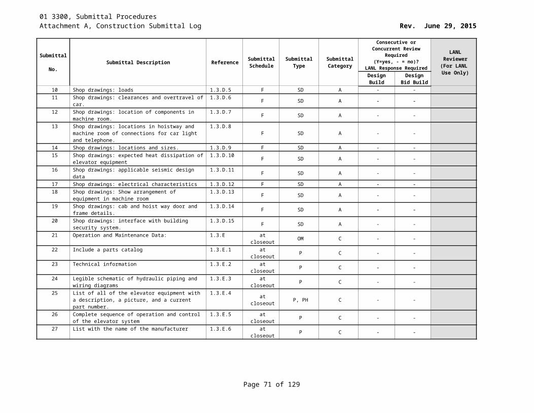
01 3300, Submittal ProceduresAttachment A, Construction Submittal Log Rev. June 29, 2015
Submittal No. Submittal Description Reference Submittal
ScheduleSubmittal
TypeSubmittal Category
Consecutive or Concurrent Review Required (Y=yes, - = no)?
LANL Response Required
LANL Reviewer
(For LANL Use Only)Design
BuildDesign Bid
Build7 Installation Instructions: Indicate application conditions
and limitations of use 1.2.A.5 W P A Y Y
8 Complete O&M instructions. Include the manufacturer’s name, and brief description of equipment and its basic operational features; include the most probable failures and the appropriate repairs; provide spare parts data for each different item of material and equipment specified; lesson plans and training manuals for the training phases
1.2.A.6.a
At Closeout P, OM C Y Y
9 Shop Drawings for each UPS: Front, side, and plan view of the UPSs; single line or three line diagrams; namplate schedule; component lists; conduit entry locations; UPS ratings including short circuit, voltage, and current; major component ratings including voltage, current, and interrupting; cable terminal sizes and types; shipping splits; bus configuration and current ratings; and features, characteristics, ratings, and factory settings.
1.2.A.7
F SD A Y Y
10 Test Reports: Detailed description of proposed factory test factory production tests specified in NEMA PE 1, and field test procedures
1.2.A.8.aU P A Y Y
11 Test Reports: Factory and field reports in booklet form 1.2.A.8.b W O,P, TR A Y Y12 Wiring Diagrams: detailed schematic wiring diagrams 1.2.A.9 W D A Y Y
26 4100 Facility Lightning Protection1 Catalog data for each component of the lightning
protection system.1.4.A.1 X CD, P A Y Y
2 Certifications demonstrating that firms meet qualifications specified in "Quality Assurance" Article.
1.4.A.2 X CT, P A Y Y
3 Bill of Materials listing lightning protection system components
1.4.A.3 W P A Y Y
4 Project record documents and drawings will all field modifications incorporated.
1.4.B.1 At Closeout RD C Y Y
5 Test reports for all inspection and testing required by this Section
1.4.B.2 At Closeout TR, P C Y Y
26 4115 Lightning Protection for Explosive Facilities1 Catalog data for each component of the lightning
protection system.1.4.A.1 X CD, P A Y Y
2 Certifications demonstrating that firms meet qualifications specified in “Quality Assurance” article.
1.4.A.2 Y CT, P A Y Y
3 Bill of Materials listing lightning protection system components
1.4.A.3 W P A Y Y
4 Project record documents and drawings with all field modifications incorporated.
1.4.B.1 At Closeout P C Y Y
5 Test reports for all inspection and testing required by this Section.
1.4.B.2 At Closeout P-TR C Y Y
26 4300 Surge Protective Devices1 Catalog Data describing SPDs. 1.3.A X P, CD A Y Y
Page 71 of 83

01 3300, Submittal ProceduresAttachment A, Construction Submittal Log Rev. June 29, 2015
Submittal No. Submittal Description Reference Submittal
ScheduleSubmittal
TypeSubmittal Category
Consecutive or Concurrent Review Required (Y=yes, - = no)?
LANL Response Required
LANL Reviewer
(For LANL Use Only)Design
BuildDesign Bid
Build2 Certifications: for Type 1 SPDs submit UL 1449 Third
Edition listing certification showing. 1) short circuit rating (SCCR)2)voltage protection ratings (VPRs)3)maximum continuous operating voltage rating (MCOV)4)type I device listing
1.3.B
X P, CT A Y Y
3 Electrical diagrams 1.3.C W ED A Y Y4 Installation Instructions 1.3.D W II A Y Y5 Operation and Maintenance Data 1.3.E At closeout OM C Y Y6 Samples 1.3.F Z S A Y Y7 Shop Drawings 1.3.G X D A Y Y8 Warranty 1.3.H At closeout P, WA C Y Y
26 5100 Interior Lighting1 Catalog data describing luminaires, lamps, and ballasts. 1.2.A.1 X P, CD A Y Y2 Performance Curves/Data: Certified photometric data for
each type of luminaire; supply-air, return-air, heat-removal, and sound performance data for air handling luminaires
1.2.A.2
X P,PD A Y Y
3 Shop drawings for non-standard luminaires. 1.2.A.3 F D A Y Y4 Warranties for luminaries and electronic ballasts per 1.6 1.2.A.4 at closeout P, WA C Y Y
26 5200 Emergency Lighting1 Catalog data describing emergency lighting. 1.2.A.1 X P, CD A Y Y2 Performance Curves/Data: certified photometric data for
each lighting unit.1.2.A.2 X P,PD A Y Y
3 Warranties for emergency lighting units and exit signs 1.2.A.3 at closeout P, WA A Y Y4 Maintenance Instructions 1.2.A.4 at closeout P, O M C Y Y
26 5600 Exterior Lighting1 Catalog Data 1.5.A.1 X CD A Y Y PE2 Performance Curves/Data 1.5.A.2 X PD A Y Y PE3 Shop Drawings 1.5.A.3 X SD A Y Y PE4 Maintenance Data 1.5.A.4 X M C Y Y PE5 Warranties 1.5.A.5 at closeout WA C Y Y PE
27 1000 Structured Cabling1 Certifications of the qualifications of the Category 6A UTP
horizontal cable1.6.A W CT, P A Y Y
2 Detailed records of cable routing 1.6.B at closeout P C Y Y3 Test reports 1.6.C at closeout P, TR C Y Y
27 1500.18 Protected Transmission System Rough-In1 Certifications of the qualifications of the fiber-optic cable
installers.1.6.A.1 W P, CT A Y Y
2 Detailed as-built documents 1.6.A.2 W D A Y Y3 As-built records of cable routing 1.6.A.3 at closeout D A Y Y
27 3000 Voice Communications1 Catalog data 1.4.A.1 X P, CD A Y Y2 Wiring diagram 1.4.A.2 W D A Y Y
Page 72 of 83
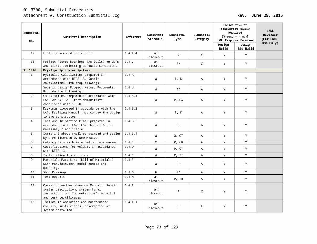
01 3300, Submittal ProceduresAttachment A, Construction Submittal Log Rev. June 29, 2015
Submittal No. Submittal Description Reference Submittal
ScheduleSubmittal
TypeSubmittal Category
Consecutive or Concurrent Review Required (Y=yes, - = no)?
LANL Response Required
LANL Reviewer
(For LANL Use Only)Design
BuildDesign Bid
Build3 Calculations 1.4.A.3 W P, CA A Y Y4 Proposed programming 1.4.A.4 W P A Y Y5 As-built documents 1.4.A.5 at closeout P, D A Y Y6 As-built records 1.4.A.6 at closeout P, D A Y Y7 Test and inspection report for the completed installation. 1.4.A.7 Y P, II A Y Y
28 0528 Pathways for Electrical Security1 Test Reports 1.5.A.1 Y P, TR A Y Y2 As-Built Drawings 1.5.A.2 at closeout D A Y Y
28 1321 Administrative Access Control System Rough-In1 Catalog Data: manufacturer's data 1.5.A.1 X P A Y Y2 Test Reports: Provide inspection and test reports 1.5.A.2 Y P, TR A Y Y3 As-Built Drawings 1.5.A.3 at closeout P, D A Y Y
28 3100 Fire Detection and AlarmNOTE: See 28 3100, Appendix A - Deliverables table to help clarify the submittal schedule
1 Certifications of the qualifications of the fire alarm installing firm
1.4.B.1 Within 30 days after Notice to Proceed
P, CT A Y Y
2 Certifications of the qualifications of the fire alarm system technician
1.4.B.2 Within 30 days after Notice to Proceed
P.CT A Y Y
3 Certification from the fire alarm control manufacturer 1.4.B.3 W P, CT A Y Y4 Calculations: Submit the following with design drawings 1.4.C.1 30 days
prior to scheduled start of fire
alarm system
installation
CA DD Y Y
5 System battery capacity calculations 1.4.C.1.a 30 days prior to
scheduled start of fire
alarm system
installation
DD Y Y
6 Voltage drop calculations 1.4.C.1.b W P, CA DD Y Y7 Design/installation drawings: 1.4.C.2 W D DD Y Y
Page 73 of 83
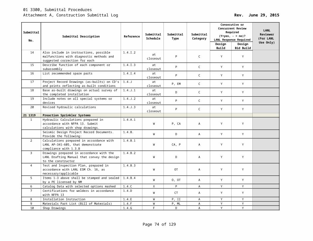
01 3300, Submittal ProceduresAttachment A, Construction Submittal Log Rev. June 29, 2015
Submittal No. Submittal Description Reference Submittal
ScheduleSubmittal
TypeSubmittal Category
Consecutive or Concurrent Review Required (Y=yes, - = no)?
LANL Response Required
LANL Reviewer
(For LANL Use Only)Design
BuildDesign Bid
Build8 Catalog Data 1.4.C.3 At least 30
days prior to
scheduled start of fire
alarm system
installation
P, CD DD Y Y
9 Installation instructions 1.4.C.4 At least 30 days prior
to scheduled start of fire
alarm system
installation
P, II DD Y Y
10 Materials and parts list 1.4.C.5 At least 30 days prior
to scheduled start of fire
alarm system
installation
P,SD DD Y Y
11 FCP Program: Submit FCP program as follows: 1.4.C.6 F DD Y Y12 FCP input/output matrix and a copy of the proposed FCP
program 1.4.C.6.a At least two
weeks prior to the
anticipated pre-test
date of the fire alarm system
P DD Y Y
13 Final FCP input/output matrix and the final FCP program 1.4.C.6.b W P DD Y Y14 O&M Manual 1.4.C.7 at closeout P, OM DD Y Y15 Submit operating and instruction manuals with the 100%
submittal of calculation and drawings1.4.C.7.a At closeout II, OM DD Y Y
16 Project-specific operating and maintenance instruction manuals
1.4.C.7.b Upon successful completion of testing
OM (5 sets) DD Y Y
17 Test Reports: as follows: 1.4.D Y TR A Y Y18 Report of the pre-final tests indicating system status and
corrective actions required before the final acceptance tests
1.4.D.1Y P, TR A Y Y
Page 74 of 83
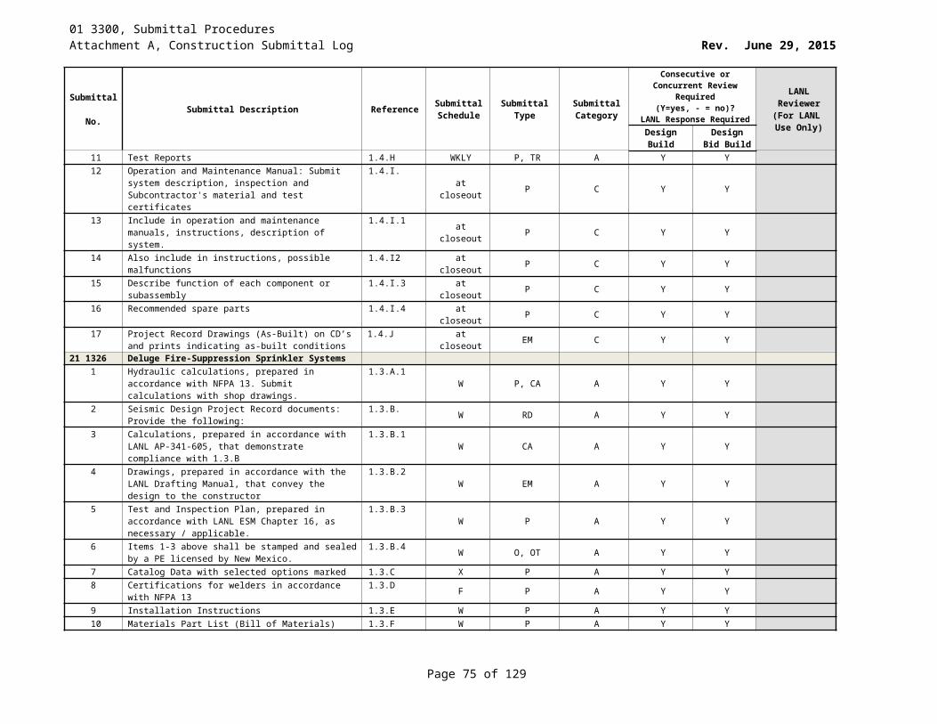
01 3300, Submittal ProceduresAttachment A, Construction Submittal Log Rev. June 29, 2015
Submittal No. Submittal Description Reference Submittal
ScheduleSubmittal
TypeSubmittal Category
Consecutive or Concurrent Review Required (Y=yes, - = no)?
LANL Response Required
LANL Reviewer
(For LANL Use Only)Design
BuildDesign Bid
Build19 Test plan for the final acceptance tests 1.4.D.2 At least 30
days prior to
scheduled final
acceptance tests.
P, TR A Y Y
20 Final “Record of Completion” and “Inspection and Testing Form” as required by NFPA 72
1.4.D.3 Upon successful completion
of acceptance
tests
A Y
21 Project record documents as follows: 1.4.E at closeout RD C Y Y22 Updated drawings reflecting as-built conditions showing
the work completed under this Section. 1.4.E.1 at closeout SD,D C Y Y
23 Updated drawings on electronic media in “.pdf” and AutoCAD -.dwg” formats.
1.4.E.2 at closeout D,EM C Y Y
24 “Record of Completion” and associated documentation for the completed system according to NFPA 72.
1.4.E.3 At closeout P, CT C Y Y
25 Warranties 1.4.F at closeout P, WA C Y Y28 3110 Fire Detection and Alarm-Addition to Existing
1 System battery capacity calculations 1.3.A.1.a F P, CA A Y Y2 Audible signal distribution calculations 1.3.A.1.b F P, CA A Y Y3 Voltage drop calculations 1.3.A.1.c F P, CA A Y Y4 Catalog data at least 30 days prior to scheduled start of
installation 1.3.A.2 W P, CD A Y Y
5 Certifications of the qualifications of the fire alarm installing firm
1.3.A.3.a W P, CT A Y Y
6 Certifications of the qualifications of the fire alarm system technician
1.3.A.3.b W P, CT A Y Y
7 Certification from the fire alarm control manufacturer 1.3.A.3.c W P, CT A Y Y8 "Certificate of Completion" and associated documentation 1.3.A.3.d Y P, CT A Y Y9 Installation instructions 1.3.A.4 W P, II A Y Y10 Materials and parts lists 1.3.A.5 W P A Y Y11 Shop drawings as follows: Floor plan drawings using a
minimum scale of 1/8" = 1-'0" for plans and 1/4" = 1'-0" for details; hand lettering ; show location of FACP, fire alarm appliances, conduit layout, quantity and type of wires in each conduit, and interface with other systems; show layout of the FACP.
1.3.A.6
F (30 days) SD A Y Y
12 Report of the pre-final tests 1.3.A.7.a WKLY P, TR A Y Y13 Test plan for the final acceptance tests 1.3.A.7.b W P, TR A Y Y14 Report of final acceptance test 1.3.A.7.c Y P, TR A Y Y15 Terminal-to-terminal wiring diagrams 1.3.A.8.a W (30 days) D A Y Y16 Operating and maintenance data. 1.3.A.9 at closeout P C Y Y17 Project Record Documents 1.3.A.10.a at closeout P,RD C Y Y
Page 75 of 83
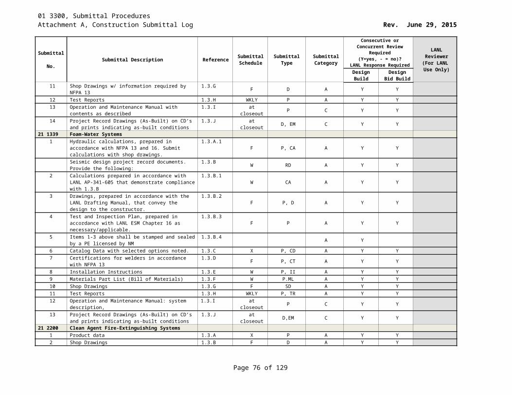
01 3300, Submittal ProceduresAttachment A, Construction Submittal Log Rev. June 29, 2015
Submittal No. Submittal Description Reference Submittal
ScheduleSubmittal
TypeSubmittal Category
Consecutive or Concurrent Review Required (Y=yes, - = no)?
LANL Response Required
LANL Reviewer
(For LANL Use Only)Design
BuildDesign Bid
Build18 Project Record Documents: Provide the updated shop
drawings 1.3.A.10.b at closeout D,EM,RD C Y Y
19 Warranties 1.3.A.11 at closeout P, WA C Y Y
31 2000 Earth Moving1 Certifications from an independent testing laboratory that
pipe bedding materials meet the specification1.4.A.1 X P, CT A - - PE
2 Certifications from an independent testing laboratory that base course materials, crushed stone or crushed or screened gravel meet the spec
1.4.A.2X P, CT A - - PE
3 Test reports of field-testing materialcompaction
1.4.A.3 Z P, TR A - - PE
4 Test reports of field-testing of tracing wire continuity 1.4.A.4 Z P, TR A - - PE5 Catalog data on identification tape and tracing wire 1.4.A.5 X P, CD A - - PE
31 2323.33 Flowable Fill1 Material certifications 1.3.A.1 W P, CT A - -2 Provide design mixes and test reports. 1.3.A.3 W ML, TR A - -3 Batch tickets. 1.3.A.2 WKLY P A - -4 Field test reports. 1.3.A.4 WKLY P, TR A - -
32 1216 Asphalt Paving1 Material certifications 1.2.A.1 W P, CT A - - PE2 Proposed design mix 1.2.A.2 W ML A - - PE3 Laboratory test reports for design mix for bituminous
pavement. 1.2.A.3 W P-TR A - - PE
4 Aggregate quality testing 1.2.A.4 W P, TR A - - PE5 Certification from the testing laboratory responsible for
material analysis and field testing1.2.A.5 W CT, P A - - PE
6 Certification that testing personnel are in compliance with ASTM D 3666
1.2.A.6 W CT, P A - - PE
7 Traffic analysis, vehicle loadings, and structural design. 1.2.A.7 W P A - - PE8 Detailed plan for temporary traffic control markings and
traffic signs1.2.A.8 W P, D A - - PE
32 3100 Fences and Gates1 Catalog data on fabric, posts, accessories, fittings, and
hardware1.3.A.1 X P, CD A - -
32 3113 Chain Link Fences and Gates1 Catalog data. 1.3.A.1 X P, CD A - -2 Copies of batch tickets for each load of concrete. 1.3.A.2 WKLY (2)P A - -
32 8400 Planting Irrigation1 Catalog data for all equipment 1.3.A.1 X P, CD A - -2 Installation instructions 1.3.A.2 W P, II A - -3 Operating and maintenance manual 1.3.A.3 at closeout P, OM C - -4 Prepare a zone chart for each controller 1.3.A.3.a F D, P A - -5 Irrigation plan 1.3.A.4 F D A - -6 Record Drawing 1.3.A.5 Z D A - -
Page 76 of 83
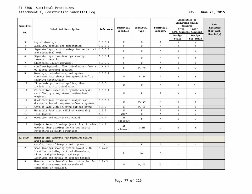
01 3300, Submittal ProceduresAttachment A, Construction Submittal Log Rev. June 29, 2015
Submittal No. Submittal Description Reference Submittal
ScheduleSubmittal
TypeSubmittal Category
Consecutive or Concurrent Review Required (Y=yes, - = no)?
LANL Response Required
LANL Reviewer
(For LANL Use Only)Design
BuildDesign Bid
Build32 9219 Seeding
1 Catalog data 1.3.A.1 X P, CD A - -2 Certification: certified seed bag tags and copies of seed
invoices identified by project name.1.3.A.2 Y S, P, CT A - -
3 Installation instructions 1.3.A.3 W P, II A - -32 9223 Sodding
1 Sod certification 1.2.A.1 W CT A - -2 Sodding schedule 1.2.A.2 W OT A - -3 Sample of materials 1.2.A.3 X S A - -
32 9300 Plants1 Planting schedule dates and type of work to be
performed. Correlate to provide specified maintenance periods. Once schedule is accepted, document reasons for delays or changes and revise dates only as approved by LANL STR.
1.3.A.1
W P, II A - -
2 Materials list with installation instructions 1.3.A.2 W P A - -3 Catalog data 1.3.A.3 X P, CD A - -
33 0513 Manholes and Structures1 Certifications; Materials 1.4.A.1 W P, CT A - -2 [NMED approved septic tank list certification number] 1.4.A.2 W P, CT A - -3 [Level alarm system product data and installation
instructions] 1.4.A.3 X P, II A - -
4 Manhole exfiltration test results 1.4.A.4 Within 5 working days of
successful test
P, TR A - -
33 1000 Water Utilities1 Catalog data 1.4.A.1 X P, CD A - -2 Installation instructions 1.4.A.2 W P, II A - -3 Existing system pressure calculations 1.4.A.3 F P A - -4 Certification of welders and qualified welding procedure 1.4.A.4 F P, CT A Y Y PE5 [Horizontal Direction Drilling] 1.4.A.5 W P A - -6 Tracing wire continuity test report 1.4.A.6 Z P, TR A - -7 Catalog data on identification tape and tracing wire 1.4.A.7 X P, CD A - -
33 3000 Sanitary Sewerage Utilities1 Catalog data 1.3.A.1 X P, CD A - -2 Certifications for Welders and Qualified Welding
Procedure1.3.A.2 W P, CT A - -
3 [Horizontal Directional Drilling] 1.3.A.3 W P A - -4 Tracing wire continuity test report 1.3.A.4 Z P, TR A - -
33 3200 Wastewater Utility Pumping Stations1 Catalog data 1.3.A.1 X P, CD A - -2 Power and Control cables 1.3.A.2 W P A - -3 Pump curves 1.3.B.1 W P A - -
Page 77 of 83
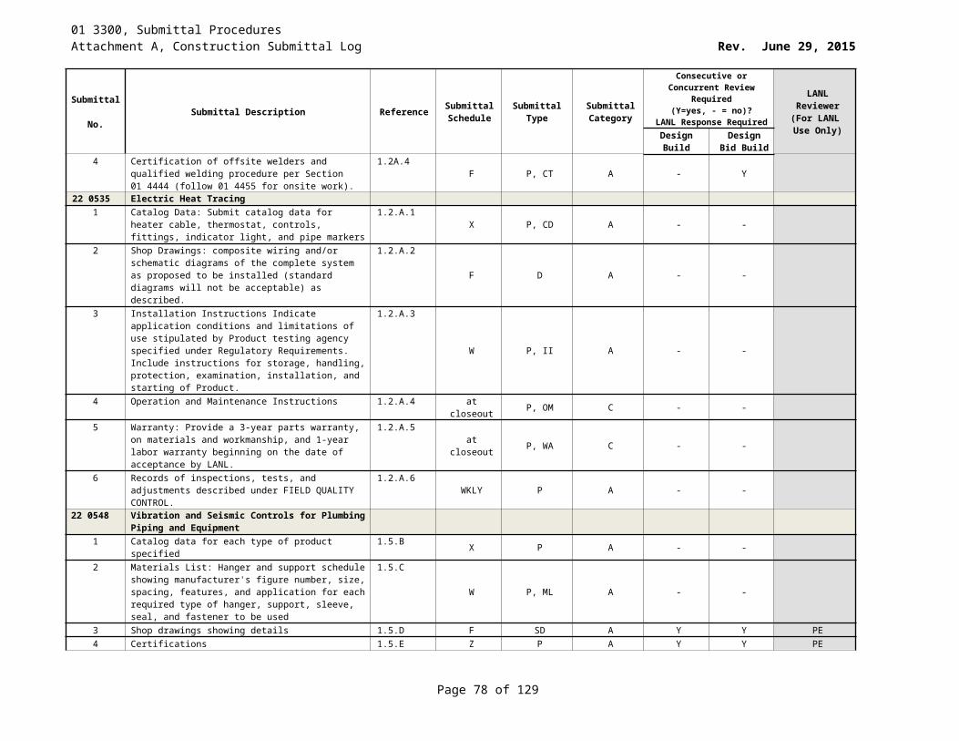
01 3300, Submittal ProceduresAttachment A, Construction Submittal Log Rev. June 29, 2015
Submittal No. Submittal Description Reference Submittal
ScheduleSubmittal
TypeSubmittal Category
Consecutive or Concurrent Review Required (Y=yes, - = no)?
LANL Response Required
LANL Reviewer
(For LANL Use Only)Design
BuildDesign Bid
Build4 Operation and maintenance data 1.3.B.2 at closeout P, OM C - -5 Theory of operation 1.3.B.2.a at closeout P C - -6 Test procedure 1.3.B.2.b at closeout P C - -7 Warranties 1.3.A.3 at closeout P, WA C - -
33 4000 Storm Drainage Utilities1 Catalog data on pipe materials, fittings, and accessories 1.3.A.1 X P, CD A - -2 Installation instructions for accessories 1.3.A.2 W P, II A - -3 Certifications for welders and qualified welding procedure 1.3.A.3 F P, CT A - -
33 5100 Natural-Gas Distribution1 Catalog data of pipe materials 1.3.A.1 X P, CD A - -2 Certified material inspection report for steel pipe 1.3.A.2 F P A - -3 Certification of welders and qualified welding procedure 1.3.A.3 F P, CT A Y Y PE4 Certified Welding Inspector (CWI) inspection report 1.3.A.4 WKLY P A - -5 [Horizontal directional Drilling] 1.3.A.5 W P A - -6 [Pipe pigging inspection report] 1.3.A.6 WKLY P A - -7 [Tracing wire continuity test report] 1.3.A.7 Z P, TR A - -8 Catalog data on identification tape [and tracing wire] 1.3.A.8 X P, CD A - -9 Total connected natural gas load in BTU’s/hr heat input
requirement for each connected device (BTU’s/hr), and pressure (psig) requirement at building wall
1.3.A.9W P, CA A - -
33 6300 Steam Energy Distribution1 Catalog data 1.4.A.1 X P, CD A - -2 Certified material test report for the pipe 1.4.A.2 F P, CT A - -3 Certification of welders and qualified welding procedures 1.4.A.3 F P, CT A Y Y PE4 Welding Process Visual Examination Report 1.4.A.4 WKLY P A Y Y PE5 Installation instructions 1.4.A.5 W P, II A - -6 Plan and profile for steam/condensate piping system 1.4.A.6 W D A - -7 Thermal Expansion calculation 1.4.A.7 W P, CA A - -
33 7119 Electrical Underground Ducts and Manholes1 Catalog Data describing pre-cast manholes, manhole
frames and lids, ladders, and cable racks1.3.A.1 Z P, CD A Y Y
2 Test Reports: duct blockage tests 1.3.A.2 Z P, TR A Y Y3 Project Record documents: Accurately record GPS-based
survey locations of ductbanks, new and existing manholes, and places where ductbanks cross other underground systems.
1.3.B.1
Y P C Y Y
33 7311 Pad-Mounted Transformer Rough-InN/A
33 7711 Pad-Mounted Switch Rough-InN/A
33 8126 Communication Underground Ducts, Manholes, and HandholesCatalog Data: Describing pre-cast manhole(s), manhole frame(s) and lid(s), ladders, and cable racks. Include data substantiating that materials comply with specified requirements
1.3.A.1
Z P, CD A Y Y
Page 78 of 83
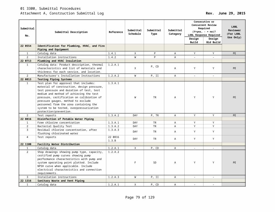
01 3300, Submittal ProceduresAttachment A, Construction Submittal Log Rev. June 29, 2015
Submittal No. Submittal Description Reference Submittal
ScheduleSubmittal
TypeSubmittal Category
Consecutive or Concurrent Review Required (Y=yes, - = no)?
LANL Response Required
LANL Reviewer
(For LANL Use Only)Design
BuildDesign Bid
BuildProject Record Documents: Accurately record GPS-based survey locations of ductbanks, new and existing manholes, and places where ductbanks cross other underground systems
1.3.B.1
Y P C Y Y
40 0511 Compression Fittings on Copper and Stainless Steel TubingN/A
40 0513 Process Piping1 For unlisted components (not listed in Table 326.1 or
Appendix A of ASME B31.3), before fabrication submit approved piping stress calculations/analyses or alternative methods that document the acceptability of the specific piping system in accordance with ASME B31.3
1.4.A.1
F CA, P A Y Y
2 Submit NDE (non-destructive examination) procedures that will be used for fabrication and examination of the piping, and pressure-leak testing and cleaning procedures
1.4.A.2F TR, P A Y Y
3 Submittals must comply with the record requirements in ASME B31.3 for welding/bonding (Section 328.2.4/A328.2.4), examination (Section 341.4.1 & 341.4.3), procedure qualification (Section 300.2), qualification (Section 328.2.4, 342.1 & A328.2.4) and test (Section 345.2.7)
1.4.A.3
F P A Y Y
40 0527 Piping and Tubing Inspection ChecklistN/A
41 2213.13 Bridge Cranes1 Certification of previous crane installations 1.3.B.1 W P, CT A - -2 Certifications for structural steel 1.3.B.2 F P, CT A - -3 Certifications for all electrical and mechanical components 1.3.B.3 F P, CT A - -4 Certification of required inspection and load testing 1.3.B.4 WKLY P, CT A - -5 Welder certifications 1.3.B.5 F P, CT A Y Y6 Certificate that the crane contains no asbestos, lead paint,
polychlorinated biphenyl’s (PCB’s), or elemental mercury. Chromates shall be avoided where feasible.
1.3.B.6W P, CT A - -
7 Product Data: Manufacturer’s catalog data for all major components. The catalog cuts shall be marked-up or supplemented with additional sheets to clearly identify the model or size, selected options, features, and/or modifications to demonstrate compliance with specification requirements. Catalog cuts which show modifications beyond the standard options and all supplemental pages shall bear original signatures and dates of the equipment manufacturer’s authorized representative. Each catalog cut and each supplemental sheet shall clearly identify the item to which it applies.
1.3.C
X P-CD A Y Y
8 Manufacturer's installation instructions 1.3.D X P, II A - -9 Performance Data 1.3.E W P,PD A - -
Page 79 of 83
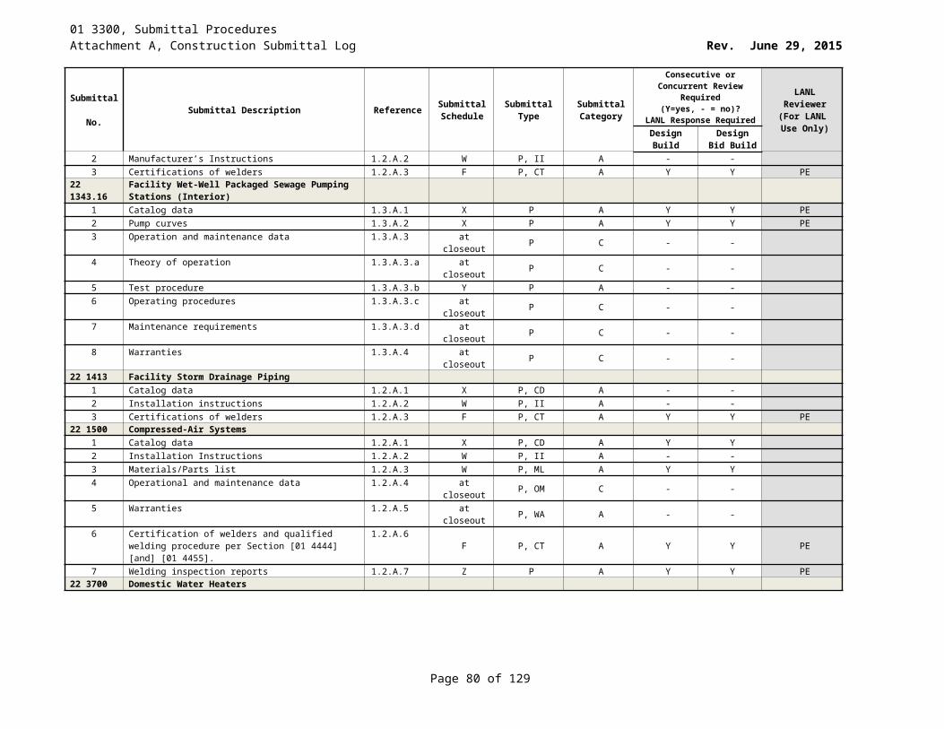
01 3300, Submittal ProceduresAttachment A, Construction Submittal Log Rev. June 29, 2015
Submittal No. Submittal Description Reference Submittal
ScheduleSubmittal
TypeSubmittal Category
Consecutive or Concurrent Review Required (Y=yes, - = no)?
LANL Response Required
LANL Reviewer
(For LANL Use Only)Design
BuildDesign Bid
BuildShop drawings: 1.3.F
10 Structural – Drawings showing the fabrication details and list of materials for the girders, trucks, and trolleys including location and size of the structural members, all weldments, fastener joints
1.3.F.1
F D A Y Y
11 Crane arrangement drawings (Plans, Sections and Elevations)
1.3.F.2 F D A Y Y
12 Bridge dive and hoist arrangement drawings (Plans, Section and Elevations)
1.3.F.3 F D A - -
13 Electrical drawings of the electrical equipment and wiring diagrams
1.3.F.4 F D A - -
Design Data: 1.3.G14 Calculations demonstrating compliance with all design
requirements, and LANL Procedure AP-341-605.1.3.G.1 F P, CA A Y Y
15 Calculations verifying compliance with Section 3 of CMAA #70 and paragraph 2.2.F.3 of this specification (Structural Design, Additional Load Combinations) for any non-commercial items.
1.3.G.2.a
F P, CA A Y Y
16 Calculations verifying design of trolley bumpers and end stops; and bridge bumpers in accordance AISE TR-06.
1.3.G.2.b F P, CA A - -
Operation and maintenance data indicating the following: 1.3.H at closeout P, OM C - -17 Information for authorized service facilities and parts
distributor1.3.H.1 at closeout P C - -
18 Parts lists 1.3.H.2 at closeout P C - -19 Recommended spare parts 1.3.H.3 at closeout P C - -20 Lubrication requirements and acceptable substitutes 1.3.H.4 at closeout P C - -21 Maintenance requirements. 1.3.H.5 at closeout P C - -22 Safety procedures 1.3.H.6 at closeout P C - -23 Proper operation of all equipment 1.3.H.7 at closeout P C - -24 Routine maintenance procedures 1.3.H.8 at closeout P C - -25 Assembly drawings and descriptive literature. 1.3.H.9 at closeout D, P C - -26 Wiring schematics 1.3.H.10 at closeout D C - -27 Written 24 month parts and labor warranty to include… 1.3.I at closeout P, WA C - -
41 2225 Hoist and Trolleys1 Quality assurance plan 1.5.A.1 Z P A Y Y2 Design data 1.5.A.2 F P A Y Y3 Weld Procedure Specifications and Procedure
Qualification Reports 1.5.A.3 F P A Y Y
4 Certification of previous hoist or trolley installations 1.5.A.4 X P, CT A Y Y5 Certified Material Test Reports and Certifications for
structural steel1.5.A.5 F P, CT A Y Y
6 Certifications for all electrical and mechanical components 1.5.A.6 F P, CT A Y Y7 Certification of required inspection and load testing 1.5.A.7 F P, CT A Y Y8 Welder certifications 1.5.A.8 F P, CT A Y Y9 Inspection Test Reports and inspector personnel
certifications1.5.A.9 WKLY P, TR A Y Y
Page 80 of 83
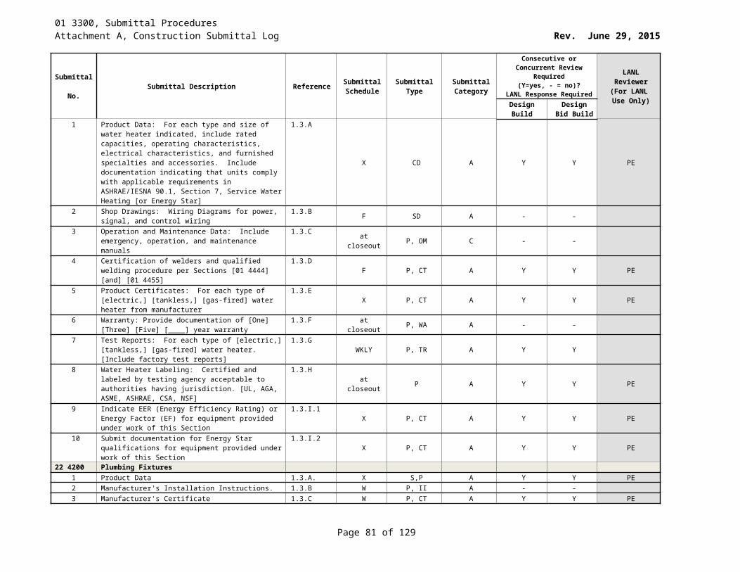
01 3300, Submittal ProceduresAttachment A, Construction Submittal Log Rev. June 29, 2015
Submittal No. Submittal Description Reference Submittal
ScheduleSubmittal
TypeSubmittal Category
Consecutive or Concurrent Review Required (Y=yes, - = no)?
LANL Response Required
LANL Reviewer
(For LANL Use Only)Design
BuildDesign Bid
BuildManufacturer’s assembly, installation, maintenance, and troubleshooting instructions including:
1.5.A.10 W P, II A Y Y
10 Information for authorized service facilities and parts distributor
1.5.A.10.a W P A Y Y
11 Parts lists 1.5.A.10.b W P A Y Y12 Recommended spare parts 1.5.A.10.c W P A Y Y13 Lubrication requirements and acceptable substitutes 1.5.A.10.d W P A Y Y14 Maintenance requirements and schedules for all
equipment1.5.A.10.e W P C Y Y
15 Safety procedures 1.4.A.10.f W P A Y Y16 Proper operation of all equipment 1.5.A.10.g W P A Y Y17 Routine maintenance procedures 1.5.A.10.h at closeout P C Y Y18 Assembly drawings and descriptive literature 1.5.A.10.i W D A Y Y19 Wiring schematics 1.5.A.10.j W D A Y Y20 [Shop Drawings, Catalog Cut sheets] 1.5.A.11 F SD A Y Y21 Structural steel fabrication drawings 1.5.A.11.a F D A Y Y22 Hoist or trolley drawings (Plans, Sections and Elevations) 1.5.A.11.b F D A Y Y23 Electrical drawings (plans, sections, elevations) 1.5.A.11.c Z D A Y Y24 Wiring diagrams: Drawings to include the following: 1.5.A.11.d Z D A Y Y25 Manufacturer’s name 1.5.A.11.d.1 Z D A Y Y26 Model number 1.5.A.11.d.2 Z D A Y Y27 Rating 1.5.A.11.d.3 Z D A Y Y28 Hook-speed/hook-load curves (hoisting and lowering) 1.5.A.11.d.4 Z D A Y Y29 Motor-speed/ torque and current curves 1.5.A.11.d.5 Z D A Y Y30 Evidence of experience 1.5.A.12 X P A Y Y31 Document inspections performed on the hoist or trolley
systems 1.5.A.13 WKLY P A Y Y
32 Certified Material Test Reports or Certificates of Conformance
1.5.A.14 Z P A Y Y
43 3113.37 High Efficiency Gas Purification Filters1 Submittal of QA plan 1.5 Z OT A - -
2 Certificate of Conformance. The CoC shall include: 1.5.A.1 F P, CT A - -3 Copy of the filter manufacturer’s QA plan 1.5.A.1.a F P, CT A Y Y4 Certification that filters and filter housing have been
designed manufactured and constructed in accordance with manufacturer’s QA plan and Section 1.6
1.5.A.1.bY P, CT A Y Y
5 Certification documentation showing that the filter meets the design requirements
1.5.A.1.c Y P, CT A Y Y
6 Certification that any custom built filter housing was fabricated and leak tested to meet the requirements of this specification.
1.5.A.1.dY P, CT A Y Y
7 Purchased item identified by model number 1.5.A.1.e Y P A Y Y8 Statement that the filter housing meets the leak test
requirements 1.5.A.1.f Y P A Y Y
Page 81 of 83
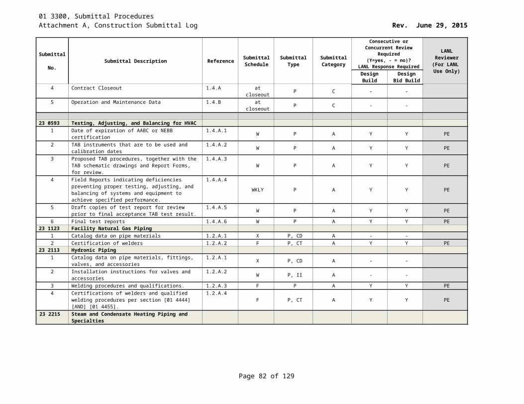
01 3300, Submittal ProceduresAttachment A, Construction Submittal Log Rev. June 29, 2015
Submittal No. Submittal Description Reference Submittal
ScheduleSubmittal
TypeSubmittal Category
Consecutive or Concurrent Review Required (Y=yes, - = no)?
LANL Response Required
LANL Reviewer
(For LANL Use Only)Design
BuildDesign Bid
Build9 Purchase Order (PO) number 1.5.A.1.g Y P A - -10 Any approved changes, waivers, or deviations from this
specification1.5.A.1.h Z P A Y Y
11 Installation Instructions 1.5.A.2 W P, II A - -12 Warranty documentation 1.5.A.3
at closeout P, WA C - -
43 4113 Gas and Liquid Pressure Vessels1 Reference to LANL Project I.D. Number, LANL
Subcontract Number. LANL may choose to waive some of these submittals if the Supplier has been granted prior approval by LANL for recent Subcontract submittals
1.5.A.1
Z P A - -
2 Design drawings, calculations, and supporting data prior to beginning pressure vessel fabrication.
1.5.B.1 F D, P, CA A Y Y
3 Quality Assurance/ Quality Control 1.5.C X OT A - -4 Uncontrolled copy of QA manual for LANL approval 1.5.C.1 X (1)P A - -5 Notifications 1.5.C.2 W P A - -6 Lower Tier Services Plan 1.5.C.3 F P A - -
7 Fabrication Schedule 1.5.C.4 F P A - -8 Material Control Procedure 1.5.C.5 X P A - -9 Material control procedure to be used in the execution of
the work. 1.5.C.5.a F P A - -
10 Heat Numbers: Note heat numbers on weld maps 1.5.C.5.b Y D, P A - -11 Fabrication Procedures: a copy of: 1.5.C.6 W A - -12 Welding Procedure Specifications (WPS) 1.5.C.6.a W P A Y Y PE13 Welding Procedure Qualification Record (PQR) 1.5.C.6.b W P A Y Y PE14 Welding & NDE Personnel Listing 1.5.C.6.c W P A Y Y PE15 Liquid Penetrant Test Procedure 1.5.C.6.d W P A Y Y PE16 Radiographic Test Procedure, and 1.5.C.6.e W P A Y Y PE17 Leak Test Procedure 1.5.C.6.f W P A Y Y PE18 Welder Performance Qualification Records 1.5.C.7.a W P, CT A Y Y PE19 NDE Personnel Certifications 1.5.C.7.b W P, CT A Y Y PE20 Material certifications for steel 1.5.C.7.c W P, CT A Y Y PE21 Supplier’s ASME “Certificate of Compliance,” 1.5.C.7.d W P, CT A Y Y PE
Test Reports: a copy of: 1.5.C.8 S TR A - -22 Liquid Penetrant Test Report 1.5.C.8.a S P, TR A Y Y PE23 Radiographic Test Report, and 1.5.C.8.b S P, TR A Y Y PE24 Hydrostatic Leak Test Report 1.5.C.8.c S P, TR A Y Y PE
Shipping Submittals: a copy of 1.5.C.9 S OT A - -25 Supplier’s vessel Cleaning Procedure 1.5.C.9.a S P A - -26 Supplier’s Packaging Procedure 1.5.C.9.b S P A - -27 Bill of Lading with shipment 1.5.C.9.c Y P A - -28 Nonconformances 1.5.D Y OT A - -29 Written request to LANL for any proposed technical
changes.1.5.D.1 W P A Y Y PE
Page 82 of 83
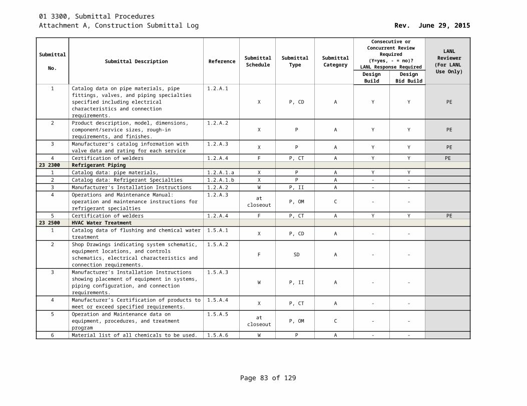
01 3300, Submittal ProceduresAttachment A, Construction Submittal Log Rev. June 29, 2015
Submittal No. Submittal Description Reference Submittal
ScheduleSubmittal
TypeSubmittal Category
Consecutive or Concurrent Review Required (Y=yes, - = no)?
LANL Response Required
LANL Reviewer
(For LANL Use Only)Design
BuildDesign Bid
Build30 Warranty 1.5.E at closeout WA A - -
43 4116 Atmospheric Tanks and Vessels1 Reference to LANL Project ID Number, LANL Subcontract
Number, Storage Tank Number, Storage Tank Title, and Drawing Number on correspondence.
1.5.BZ P A - -
2 Drawings, Calculations and Supporting Data 1.5.B.1 F D, CA A - -3 Design drawings, calculations, and supporting data prior
to beginning storage tank fabrication. 1.5.B.1.a F P, D,CA A - -
4 Quality Assurance/Quality Control 1.5.B.2 F OT A - -5 Uncontrolled copy of the Supplier’s QA manual for LANL
approval1.5.B.2.a F P A - -
6 Notifications 1.5.B.2.b W OT A - -7 Lower Tier Services Plan 1.5.B.2.c F P A - -8 Fabrication Schedule 1.5.B.2.d F P A - -9 Material Control Procedure 1.5.B.2.e F P A - -10 Welding Procedure Specifications (WPS) 1.5.B.2.f.i F P A - -11 Welding Procedure Qualification Record (PQR) 1.5.B.2.f.ii F P A - -12 Welding & NDE Personnel Listing 1.5.B.2.f.iii F P A - -13 Liquid Penetrant Test Procedure 1.5.B.2.f.iv F P A - -14 Radiographic Test Procedure 1.5.B.2.f.v F P A - -15 Leak Test Procedure 1.5.B.2.f.vi F P A - -16 Certifications: a copy of: 1.5.B.2.g F CT A - -17 Welder Performance Qualification Records 1.5.B.2.g.i F P, CT A Y Y PE18 NDE Personnel Certifications 1.5.B.2.g.ii F P, CT A Y Y PE19 Material certifications 1.5.B.2.g.iii F P, CT A Y Y PE20 Test Reports: a copy of: 1.5.B.2.h S P, TR A - -21 Liquid Penetrant Test Report 1.5.B.2.h.i S P, TR A Y Y PE22 Radiographic Test Report. 1.5.B.2.h.ii S P, TR A Y Y PE23 Leak Test Report. 1.5.B.2.h.iii S P-TR A Y Y PE24 Shipping Submittals: a copy of: 1.5.B.2.i Y OT A - -25 Supplier’s vessel Cleaning Procedure 1.5.B.2.i.i Y P A - -26 Supplier’s Packaging Procedure. 1.5.B.2.i.ii S P A - -27 Bill of Lading with the storage tank shipment. 1.5.B.2.i.iii Y P A - -28 Nonconformances 1.5.B.3 S OT A - -29 Warranty 1.5.B.4 at closeout P, WA C - -
Page 83 of 83