![[Andy Crowe PMP PgMP] the PMP Exam Quick Referen(BookZZ.org)](https://static.fdocuments.in/doc/165x107/577c79d11a28abe054940b45/andy-crowe-pmp-pgmp-the-pmp-exam-quick-referenbookzzorg.jpg)
[Andy Crowe PMP PgMP] the PMP Exam Quick Referen(BookZZ.org)

INSTRUMENTATION WITH QUALITY ENGINEERINGINSTRUMENTATION WITH QUALITY ENGINEERING
INSTRUMENTS INC INSTRUMENTS INC
reg
FREZE-PMP-gtONLOWTEMP-PMPgtOFSYSTEM OVERRIDE MESSAGES on the LOWER LCD LINE as followsFLASH
PG 4PG 3
PG 2PG 1
LCD DISPLAYThe LCD display has 2 lines of 20 characters each The first line permanently displays the COLLECTOR and the STORAGE temperatures The second line can be paged by pressing the button located just below the LCD display The following 4 pages display all system information including OVERRIDE messages
- Two industrial 400degF (204degC) rated 10 K thermistors with +- 1degF accuracy are included
- Two auxiliary thermistor inputs for optional sensors that can be located up to 1000rsquo away
- Selectable overrides for low temperature shut down or freeze protection modes for safe operation
MAIN FEATURES
- PV POWERED from 0 VDC to 22 VDC with SMART power management at very low PV power levels ldquoA mustrdquo for
soft PUMP starts and smooth controller operation
- Microprocessor accuracy and dependability with ambientoperation from -10 to 120 F
- Large easy-to-read 40 character (20x2) backlit LCD display showing every parameter measured and controlled
by the microprocessor
- PC DATA PORT with built-in transmitter allows optionaladapter and up to 500 ft cable to interface with computersfor ease in startup and remote diagnostics Or for addingan Optional large 80 character (4x20) backlit LCD display
Remote-mount up to 150 ft distances with a CAT-5 cable
- Long-term diagnostics and data logging is possible usingcommunications software that is included in Windowsrsquo OS
- Fault LED indicators for quick servicing and diagnostics
- Features for fast installation and wiring
- Electrostatic discharge protected
- Polyester coated 16 gage rugged steel enclosure with 12rdquoconduit holes for permanent wiring
deg
PR SOLR-2EDW-D2
SERVICE AND INSTALLATION INSTRUCTIONSPV POWERED
DIFFERENTIAL TEMPERATURE CONTROLLER
EAGLE D2EAGLE D2
Tel 715- 253-2801 Ver11-18-2008Fax 715- 253-2811Web wwwsolarimcinstrumentscom
468 Liberty DriveWittenberg WI 54499 USA
INSTRUMENTATION WITH QUALITY ENGINEERINGINSTRUMENTATION WITH QUALITY ENGINEERING
INSTRUMENTS INC INSTRUMENTS INC reg
IMPORTANT NOTICEThese EAGLE Series Temperature Controls are intended to control equipment under normal operating conditions Where failure or malfunction of EAGLE Series Control could lead to an abnormal operating condition that could cause personal injury or damage to the equipment or other property other devices (limit or safety controls) or systems (alarm or supervisory) intended to warn of or protect against failure or malfunction of the EAGLE Series Control must be incorporated into and maintained as part of the control system
deg deg
degdeg
degdeg
CONTROLLER OPERATION
TEMPERATURE DIFFERENCE CONTROL- When the temperature difference between the sensor on the solar collector and the sensor in the storage tank exceeds the dialed temperature difference setting (ON DIF) the PUMP relay will actuate after a 30 second delay The BLUE LED indicator will also turn ON When the temperature difference decreases and falls below 4 F (22 C) the PUMP relay and the BLUE LED indicator will turn off without delay
HIGH LIMIT CONTROL- When the temperature in the storage tank exceeds the HI-LIMIT dialed setting the PUMP relay will be turned OFF without delay regardless of the status of the temperature difference that exists between the STORAGE tank and the solar COLLECTOR The BLUE LED indicator will also turn OFF When the storage tank temperature falls 4 degrees below the setting in the HI-LIMT the controller will then resume normal operation The PUMP relay will always have a 30 second delay before switching ON and the BLUE LED will always show its STATUS condition
LOW TEMPERATURE SHUT-DOWN OVERRIDE- This feature is available to prevent the system from operating at low outdoor temperatures If this feature is enabled normal operation will stop when the COLLECTOR temperature falls below 50 F The PUMP relay will then be turned OFF Normal control operation will not resume until the COLLECTOR temperature returns to 70 F or above To enable this feature a jumper must be placed onto the jumper pins marked ldquoLOrsquo on the circuit board Only ONE of these two override features can be enabled
FREEZE PROTECTION OVERRIDE- This feature is available to prevent a non-drain back ldquowater onlyrdquo system from freezing when the outdoor temperature drops too low If this feature is enabled normal operation will stop when the COLLECTOR temperature falls below 37 F The PUMP relay will then be turned ON until the COLLECTOR temperature reaches 52 F Normal control operation will resume above this temperature To enable this feature a jumper must be placed onto the jumper pins marked ldquoFZrsquo on the circuit board Only ONE of these two override features can be enabled
STATUS INDICATION LEDS- There are four status indication LEDS The GREEN LED indicates that the microprocessor is POWERED and the SOLAR controller is running The BLUE LED indicates PUMP operation When ON the PUMP is operating and solar energy is being stored in the STORAGE tank The AMBER LED indicates if the UPPER LIMIT temperature in the storage has been exceeded The RED LED indicates when there is a fault condition The conditions that can cause the fault LED to turn ON are as follows OPEN or SHORTED or OUT of RANGE temperature SENSORS pump RELAY SWITCH NOT set to ldquoAUTrdquo (automatic) position and internal component malfunctions The RED LED will always be FLASHING when the FAULT indication is ON
SENSORS- Industrial 400degF (204degC) rated 10K IMC thermistors have +- 1degF accuracy When installed they will not exceed ONE degree of additional error for cable distances up to 1000 feet of 18ga 700 feet of 20ga or 500 feet of 22ga
SENSOR SCREW TERMINALS- There are 9 screws on a GREEN block located at the top edge of the board These terminals accept solid or stranded wire from 18ga to 22ga They are NEC class 2 circuit connections
POWER AND RELAY TERMINALS- This model operates from 475 Vdc to 22 Vdc 250 milliwatts Operationbelow 475 Vdc is prevented by the smart POWER MANAGER including initial PUMP start ups untill there is sufficient PV power for proper PUMP operation Operation above 22 Vdc could damage the controller and will void the Warranty The SOLID STATE relay is rated for 5 amps continuous load and has only NORMALY OPEN CONTACTS Its LOW SIDE contacts are internally GROUNDED The PUMP is connected between the PV PLUS and the open RELAY terminal (See suggested wiring diagram)
INSTRUMENTATION WITH QUALITY ENGINEERINGINSTRUMENTATION WITH QUALITY ENGINEERING
INSTRUMENTS INC INSTRUMENTS INC reg
COL=1741 STO= 1 10 4PKH =18 04 PKL= 6 0 1AX1=-105 AX2= 17 5 3PMP= O N UPL=ON
COL=1741 STO= 1 10 4PKH =18 04 PKL= 6 0 1AX1=-105 AX2= 17 5 3PMP= O N UPL=ON
COL=1741 STO= 1 10 4PKH =18 04 PKL= 6 0 1D I F=0 8 0 H IL= 17 5 3PMP= O N UPL=ON
COL=1741 STO= 1 10 4PKH =18 04 PKL= 6 0 1D I F=0 8 0 H IL= 17 5 3PMP= O N UPL=ON
PAGE 2
PAGE 1
An IMC LCD MASTER DIGITAL DISPLAY SOLR-RD84 can also be connected to the DATA PORT (DO NOT USE SOLR-RD80 as this display will overload the controller) The display has an RJ-45 jack and is supplied with a 3 foot long cable that can be substituted with a standard CAT5 cable up to150 feet long These ethernet cables are available at most retail stores The display panel also has a PEAK RESET button located on the side to reset previous STORAGE temperature peaks
The Information on the LCD MASTER DISPLAY PANEL is displayed as follows
COLLECTOR TEMPERATURE STORAGE TEMPERATUREDIFFERENTIAL CONTROL SETTINGHI LIMIT CONTROL SETTINGPUMP STATUSUPPER LIMIT STATUS PEAK HI= MAXIMUM TEMPERATUREPEAK LO= MINIMUM TEMPERATUREAUXILIARY SENSORS 1 AND 2
This Master LCD has a second page that will display the auxiliary sensor temperatures To display press and release the PAGERESET button on the side of the display housing The auxiliary sensors will be displayed within 2 seconds To RESET the STORED PEAK temperatures of the storage tank press and hold for 6 seconds the PAGERESET button The current temperatures will appear after the button is released The Master LCD display is updated
DATA-PORT
Requires an IMC Data-Port ADAPTER that will allow interface to a standard computerrsquos serial RS232 port The ADAPTER can also accept a serial to USB converter to connect directly to portable computers that only have USB ports If wireless operation is desired for short distances BLUE TOOTH transceiver can also be connected The rate at which the data is sent from the EAGLE solar controller is determined by a jumper in the controller as show in the CONTROLLER diagram on page 4 If the jumper is placed on position labeled ldquo2Srdquo one complete line of ldquototal system informationrdquo will be sent to the computer every 2 seconds which is necessary when performing diagnostics or a system startup If the same jumper is placed on position labeled rdquo6Mrdquo then data will be sent every 6 minutes This will allow a more suitable data-send rate for long-term DATA LOGGING specially when storing the data in a ldquoCAPTURErdquo file setup in the computerrsquos communications program such as ldquoTerminalrdquo or ldquoHyper Terminalrdquo
SAMPLE DATA PORT PRINT
RUNTIME COLL-T STOR-T DIFF-T HILI-T AUX-1 AUX-2 PUMP UPLim FAULT000 1259 737 080 1100 2122 2054 ON OFF System collecting solar HEAT006 259 737 080 1100 2122 2054 OFF OFF LO-TMP-gtOFF System in LO TEMP shut down PUMP-gtOFF012 259 737 080 1100 2128 2054 ON OFF PmpSW Pump switch ON018 OPENS 739 080 1100 2128 2054 OFF OFF SENS PmpSW Open sensor pump switch OFF024 -160 747 080 1100 259 1846 ON OFF FREZE-PMP-gtON System in Freeze protect mode PUMP-gtON030 SHRTS 749 080 1100 259 1546 OFF OFF Shorted sensor-gtSystem OFF036 1259 1737 080 1730 1122 954 OFF ON Storage reached UPPER LIMIT
INSTRUMENTATION WITH QUALITY ENGINEERINGINSTRUMENTATION WITH QUALITY ENGINEERING
INSTRUMENTS INC INSTRUMENTS INC reg
CONTROLLER RATING PRODUCT With conduit holes for permanent wiring - 5 AMP SOLR-2EDW-D2
RJ-45
HIGH LIMIT DIAL-ADJKNOB STYLE VARIES
EG- EARTH GROUND
POWER WIRING PERLOCAL CODES-USE 18 GA SLD OR18 TO 14 GA STRD
MOUNT ENCLOSURE WITH 2 10 SCREWS SPACED 525 IN
FOUR frac12rdquo CONDUITHOLES HERE amp SIDES
DIFFERENTIALDIAL-ADJKNOB STYLE VARIES
SWITCHED SUPPLYSS RLY- 5A MAX(+DC)(FUSED 7A) CONNECTTO DC PUMP OR FAN
CIRCUIT POWERNORM= 5 TO 17VDCMAX= 0 TO 22VDCAT 12 WATT MAX
CONNECT PERDIAGRAM IN INSTRUCTION MANUAL
TEMPERATURE SENSORS (4)SHD- CABLE SHIELDS COL- COLLECTOR STO- STORAGEAX1 amp 2- OPTIONAL
USE 18rdquo WIDE BLADE SCREW DRIVER TURN CCW TO OPENHOLE FOR WIRE (22 TO 18 GA)
OVERRIDE JUMPERS (ONE OR NONE)FZ- FREEZE PROTECT (37 ON 52 OFF)LO- LOW LIMIT COL (50 OFF 70 ON)
RELAY (PUMP) OVERRIDE SWITCHAUT- NORMAL SETTING
DATA PORTREMOTE DISPLAY ORCOMPUTER RS232UPDATE INTERVAL6 MIN 2 SEC
PR SOLR-2EDW-D2 REV 11-15-08
Product SOLR-2EDW-D2 With Conduit Holes for PermanentWiring
Input Power 0250 Watts 12 VDC
Relay Contact Type Normally OpenSS RLY- 5 amps DC motor 17vdc maxAction- 30 sec delay ON no delay OFF
Differential Adjustable 8 to 24 F fixed 4 F resetHigh Limit Adjustable from 110 to 200 FAccuracy +- 1 FSensors 10K 77 F (25 C) Rated to 400 FEnvironmental -10 to 120 F 0 to 95 RHDimensions 500rdquoW x 612rdquoH x 250rdquoDWeight Appx 20 lbs without power cord
0 V min to 22 VDC max Warranty is VOID if voltage exceeds 22 VDC
deg degdeg
degdeg deg degdeg
SPECIFICATIONS
INSTRUMENTATION WITH QUALITY ENGINEERINGINSTRUMENTATION WITH QUALITY ENGINEERING
INSTRUMENTS INC INSTRUMENTS INC reg
INSTALLATION
MOUNTING- The Eagle line of SOLAR controllers are designed to be mounted indoors protected from rain and condensing moisture Use two 10 screws in the enclosure ldquokeyholesrdquo for mounting
POWER WIRING- Use a and turn CCW to open the terminal hole Then insert the wire end (38rdquo) and tighten CW These terminal connections are designed for 18 ga solid copper or 18 to 14 ga stranded copper All wiring must be done in accordance with local codes Line and power wires should NOT be bundled with or placed in the same conduit with sensor or data cables
SENSOR INSTALLATION AND WIRING- Sensor installation should be in a manner as to permit proper sensor contact of the areas to be measured Shield andor insulate the sensors to prevent them from being affected by the surrounding ambient temperatures Sensor wiring installed outdoors must be rated for OUTDOOR use
It is recommended in todayrsquos Radio interference ldquoRICHrdquo environment that all sensor wiring be shielded
The cable SHIELDS must be brought to the shield grounding terminal that is the rightmost position on the GREEN terminal block See controller layout diagram For ease of shield installation insert one short wire in the shield terminal labeled ldquoSHLDrdquo and connect all the shields together with a ldquowire-nutrdquoor other reliable means Ungrounded shields may result in damage to the Solar controller circuits The shield requires grounding at the controller side ONLY DO NOT attempt to ground the collector panel with the sensor shield
For efficient and reliable wire connections strip 38rdquo (slightly shorter than block width) of insulation from an undamaged wire end Use a strip tool that will not nick the conductors If wire is solid make sure that the tip is NOT pinched or deformed so that it will fit into the terminal hole easily If the wire is stranded make sure the strands are tightly twisted Using a elect the appropriate screw and turn CCW to open the terminal hole fully Then guide the wire into the terminal hole and hold while tightening (turn CW) the screw to clamp the wire
slip off the screw and damage any circuit components If the wire is stranded make sure that ALL the strands are properly clamped in the terminal
COLLECTOR GROUNDING- The Solar collector panel array ldquomust be GROUNDEDrsquo directly to an earth ground line This is necessary to prevent damage from nearby lightening strikes which induce very DAMAGING high voltages in all nearby ungrounded metallic surfaces Please consult local state and federal codes for proper grounding
DATA LOGGING TO A COMPUTER- All the EAGLE Solar controllers can be connected to the serial port of a PC or Laptop computers An IMC DATA PORTRS232 adapter is required The maximum recommended adapter cable length is 500 feet All Windows operating systems have a communications programs such as ldquoTerminalrdquo or ldquoHyper Terminalrdquo which are used to receive andor CAPTURE data from the PCrsquos serial port This feature is ldquoEXTREMELYrdquo valuable in starting up newly installed SOLAR systems Long-term data logging is now possible which can be very useful in service and diagnostics of intermittent malfunctions Complete ldquosystem statusrdquo including temperature is presented in a line by line format including timer information In applications were the computerrsquos interface is going to be permanent it is recommended that the EAGLE WEB model be used in order to protect the connecting computer from electrical surges
Please visit our website for news or more detailed instruction at ldquowwwsolarimcinstrumentscomrdquo
18 (3mm) wide blade screwdriver
All connections exposed to the weather must be made with waterproof ldquooutdoorrdquo rated connectors
Listed below are a few suggested wire part numbers Wire selected must also meet local codes and be rated for indooroutdoor use by its manufacturer
1) ldquoPLTCrdquo Belden 9322 (22ga) or 9320 (20ga) Best specifications2) ldquoControlrdquo Belden 8761 (22ga) or 8762 (20ga) Better specifications3) ldquoAudiordquo Belden 9451-10 Black (22ga) Acceptable specifications
18 (3mm) wide blade screwdriver s
WARNING- If a 532 (4mm) wide screwdriver blade is used the screw retaining edge of the hole will be scraped off allowing the screw to fall out DO NOT reverse the screw turning directions and place the wire outside the metal CAGE creating an unreliable connection DO NOT
INSTRUMENTATION WITH QUALITY ENGINEERINGINSTRUMENTATION WITH QUALITY ENGINEERING
INSTRUMENTS INC INSTRUMENTS INC reg
PC Data-Port Adapter RS-232 SOLR-DA10
Connects directly to the EAGLE controller DATA-PORT and permits serial PC communication at 2400 BAUD rate non-isolated
Adapter has a 7 foot cable terminated with an RJ-45 plug
EAGLE ldquowebrdquo controller with a 2500 volt isolated PORT isrecommended for long-term or permanent installations Includes electronic circuits
inside the DB-9 connector housing
Immersion style4long with 14NPT fitting- SOLR-TS04
12NPT fitting- SOLR-TS248long with 14NPT fitting- SOLR-TS05
12NPT fitting- SOLR-TS25
Screw-in style SOLR-TS0312-NPT threaded plug
Bolt-on style SOLR-TS02
ACCESSORIES
THERMISTOR TEMPERATURE SENSORS-
ORATED TO 400 F
INSTRUMENTATION WITH QUALITY ENGINEERINGINSTRUMENTATION WITH QUALITY ENGINEERING
INSTRUMENTS INC INSTRUMENTS INC reg
DATE 11-18-2008
110 VACADAPTEROUTPUT 9VDC
AMPS-
++-
EAGLE Model PV POWERED SOLAR
HOT WATER SYSTEM
Supply Voltage 0 VDC to 22 VDC max
SOLR-2EDW-D2
12 VDC PUMP
SOLID STATE RELAYMAX CURRENT 5 AMPS or MAX POWER60 WATTS
FOR FREEZE PROTECTION ANDNIGHT USE
PV PANEL
ldquoABSOLUTE MAXIMUM 22 VDCrdquo
Eagle ModelSOLR-2EDW-D2
THIS ADAPTER DOES NOT PROVIDE POWER TO THE EAGLE 2 CONTROLLER ANDOR PUMP WHILE THE PV PANELIS EXPOSED TO THE DAILY SOLAR CYCLE
PV+
PV-
RELAY+
_
TO BE DETERMINED BY PUMP SIZE
If you require freeze protection as well a night viewing of the controller you can add a low power AC adapter to provide power in sun down conditions as shown above If is not required then omit AC adapter and diodes
SS RELAY AUX2
AUX1STOCOLL INTERNAL
CONNECTION
EARTH GND
RELAY
PV+PV-
POWERSENSORS
COL=801 STO=744DIF =80 HIL=843COL=801 STO=744DIF =80 HIL=843
EAGLE-D2DIFFERENTIALCONTROLLER
EAGLE-D2DIFFERENTIALCONTROLLER
SEE NOTE BELOW
INSTRUMENTATION WITH QUALITY ENGINEERINGINSTRUMENTATION WITH QUALITY ENGINEERING
INSTRUMENTS INC INSTRUMENTS INC reg
PC Data-Port Adapter RS-232 SOLR-DA10
Connects directly to the EAGLE controller DATA-PORT and permits serial PC communication at 2400 BAUD rate non-isolated
Adapter has a 7 foot cable terminated with an RJ-45 plug
EAGLE ldquowebrdquo controller with a 2500 volt isolated PORT isrecommended for long-term or permanent installations Includes electronic circuits
inside the DB-9 connector housing
Immersion style4long with 14NPT fitting- SOLR-TS04
12NPT fitting- SOLR-TS248long with 14NPT fitting- SOLR-TS05
12NPT fitting- SOLR-TS25
Screw-in style SOLR-TS0312-NPT threaded plug
Bolt-on style SOLR-TS02
ACCESSORIES
THERMISTOR TEMPERATURE SENSORS-
ORATED TO 400 F
INSTRUMENTATION WITH QUALITY ENGINEERINGINSTRUMENTATION WITH QUALITY ENGINEERING
INSTRUMENTS INC INSTRUMENTS INC reg
DATE 11-18-2008
110 VACADAPTEROUTPUT 9VDC
AMPS-
++-
EAGLE Model PV POWERED SOLAR
HOT WATER SYSTEM
Supply Voltage 0 VDC to 22 VDC max
SOLR-2EDW-D2
12 VDC PUMP
SOLID STATE RELAYMAX CURRENT 5 AMPS or MAX POWER60 WATTS
FOR FREEZE PROTECTION ANDNIGHT USE
PV PANEL
ldquoABSOLUTE MAXIMUM 22 VDCrdquo
Eagle ModelSOLR-2EDW-D2
THIS ADAPTER DOES NOT PROVIDE POWER TO THE EAGLE 2 CONTROLLER ANDOR PUMP WHILE THE PV PANELIS EXPOSED TO THE DAILY SOLAR CYCLE
PV+
PV-
RELAY+
_
TO BE DETERMINED BY PUMP SIZE
If you require freeze protection as well a night viewing of the controller you can add a low power AC adapter to provide power in sun down conditions as shown above If is not required then omit AC adapter and diodes
SS RELAY AUX2
AUX1STOCOLL INTERNAL
CONNECTION
EARTH GND
RELAY
PV+PV-
POWERSENSORS
COL=801 STO=744DIF =80 HIL=843COL=801 STO=744DIF =80 HIL=843
EAGLE-D2DIFFERENTIALCONTROLLER
EAGLE-D2DIFFERENTIALCONTROLLER
SEE NOTE BELOW
VER 11-18-08 PRINTED IN USAINSTRUMENTATION WITH QUALITY ENGINEERINGINSTRUMENTATION WITH QUALITY ENGINEERING
INSTRUMENTS INC INSTRUMENTS INC reg
COL=1741 STO= 1 10 4PKH =18 04 PKL= 6 0 1AX1=-105 AX2= 17 5 3PMP= O N UPL=ON
COL=1741 STO= 1 10 4PKH =18 04 PKL= 6 0 1AX1=-105 AX2= 17 5 3PMP= O N UPL=ON
ACTUAL SIZE DISPLAYwhen printed booklet size
ACTUAL SIZE DISPLAYwhen printed booklet size
IMPORTANT NOTICE
Do NOT attempt to connect any ETHERNET device or any other non-IMC devices to the RJ-45 DATA-PORT of any IMC CONTROLLER or accessory This will result in damage to the connected equipment Connect ONLY devices specifically designed by IMC Instruments to be connected to these ports
ACCESSORIES continued
LCD MASTER DIGITAL DISPLAY PANEL- SOLR-RD84 (very low power consumption) Displays temperature and status indication with 80 characters (4x20) 14rdquo high Supplied with a 3rsquo foot CAT-5 cable that connects directly to the EAGLE controller Data-PortHousing dimensions are 433rdquo (110mm) wide x 234rdquo (82mm) high x 173rdquo (44mm) deep

INSTRUMENTATION WITH QUALITY ENGINEERINGINSTRUMENTATION WITH QUALITY ENGINEERING
INSTRUMENTS INC INSTRUMENTS INC reg
IMPORTANT NOTICEThese EAGLE Series Temperature Controls are intended to control equipment under normal operating conditions Where failure or malfunction of EAGLE Series Control could lead to an abnormal operating condition that could cause personal injury or damage to the equipment or other property other devices (limit or safety controls) or systems (alarm or supervisory) intended to warn of or protect against failure or malfunction of the EAGLE Series Control must be incorporated into and maintained as part of the control system
deg deg
degdeg
degdeg
CONTROLLER OPERATION
TEMPERATURE DIFFERENCE CONTROL- When the temperature difference between the sensor on the solar collector and the sensor in the storage tank exceeds the dialed temperature difference setting (ON DIF) the PUMP relay will actuate after a 30 second delay The BLUE LED indicator will also turn ON When the temperature difference decreases and falls below 4 F (22 C) the PUMP relay and the BLUE LED indicator will turn off without delay
HIGH LIMIT CONTROL- When the temperature in the storage tank exceeds the HI-LIMIT dialed setting the PUMP relay will be turned OFF without delay regardless of the status of the temperature difference that exists between the STORAGE tank and the solar COLLECTOR The BLUE LED indicator will also turn OFF When the storage tank temperature falls 4 degrees below the setting in the HI-LIMT the controller will then resume normal operation The PUMP relay will always have a 30 second delay before switching ON and the BLUE LED will always show its STATUS condition
LOW TEMPERATURE SHUT-DOWN OVERRIDE- This feature is available to prevent the system from operating at low outdoor temperatures If this feature is enabled normal operation will stop when the COLLECTOR temperature falls below 50 F The PUMP relay will then be turned OFF Normal control operation will not resume until the COLLECTOR temperature returns to 70 F or above To enable this feature a jumper must be placed onto the jumper pins marked ldquoLOrsquo on the circuit board Only ONE of these two override features can be enabled
FREEZE PROTECTION OVERRIDE- This feature is available to prevent a non-drain back ldquowater onlyrdquo system from freezing when the outdoor temperature drops too low If this feature is enabled normal operation will stop when the COLLECTOR temperature falls below 37 F The PUMP relay will then be turned ON until the COLLECTOR temperature reaches 52 F Normal control operation will resume above this temperature To enable this feature a jumper must be placed onto the jumper pins marked ldquoFZrsquo on the circuit board Only ONE of these two override features can be enabled
STATUS INDICATION LEDS- There are four status indication LEDS The GREEN LED indicates that the microprocessor is POWERED and the SOLAR controller is running The BLUE LED indicates PUMP operation When ON the PUMP is operating and solar energy is being stored in the STORAGE tank The AMBER LED indicates if the UPPER LIMIT temperature in the storage has been exceeded The RED LED indicates when there is a fault condition The conditions that can cause the fault LED to turn ON are as follows OPEN or SHORTED or OUT of RANGE temperature SENSORS pump RELAY SWITCH NOT set to ldquoAUTrdquo (automatic) position and internal component malfunctions The RED LED will always be FLASHING when the FAULT indication is ON
SENSORS- Industrial 400degF (204degC) rated 10K IMC thermistors have +- 1degF accuracy When installed they will not exceed ONE degree of additional error for cable distances up to 1000 feet of 18ga 700 feet of 20ga or 500 feet of 22ga
SENSOR SCREW TERMINALS- There are 9 screws on a GREEN block located at the top edge of the board These terminals accept solid or stranded wire from 18ga to 22ga They are NEC class 2 circuit connections
POWER AND RELAY TERMINALS- This model operates from 475 Vdc to 22 Vdc 250 milliwatts Operationbelow 475 Vdc is prevented by the smart POWER MANAGER including initial PUMP start ups untill there is sufficient PV power for proper PUMP operation Operation above 22 Vdc could damage the controller and will void the Warranty The SOLID STATE relay is rated for 5 amps continuous load and has only NORMALY OPEN CONTACTS Its LOW SIDE contacts are internally GROUNDED The PUMP is connected between the PV PLUS and the open RELAY terminal (See suggested wiring diagram)
INSTRUMENTATION WITH QUALITY ENGINEERINGINSTRUMENTATION WITH QUALITY ENGINEERING
INSTRUMENTS INC INSTRUMENTS INC reg
COL=1741 STO= 1 10 4PKH =18 04 PKL= 6 0 1AX1=-105 AX2= 17 5 3PMP= O N UPL=ON
COL=1741 STO= 1 10 4PKH =18 04 PKL= 6 0 1AX1=-105 AX2= 17 5 3PMP= O N UPL=ON
COL=1741 STO= 1 10 4PKH =18 04 PKL= 6 0 1D I F=0 8 0 H IL= 17 5 3PMP= O N UPL=ON
COL=1741 STO= 1 10 4PKH =18 04 PKL= 6 0 1D I F=0 8 0 H IL= 17 5 3PMP= O N UPL=ON
PAGE 2
PAGE 1
An IMC LCD MASTER DIGITAL DISPLAY SOLR-RD84 can also be connected to the DATA PORT (DO NOT USE SOLR-RD80 as this display will overload the controller) The display has an RJ-45 jack and is supplied with a 3 foot long cable that can be substituted with a standard CAT5 cable up to150 feet long These ethernet cables are available at most retail stores The display panel also has a PEAK RESET button located on the side to reset previous STORAGE temperature peaks
The Information on the LCD MASTER DISPLAY PANEL is displayed as follows
COLLECTOR TEMPERATURE STORAGE TEMPERATUREDIFFERENTIAL CONTROL SETTINGHI LIMIT CONTROL SETTINGPUMP STATUSUPPER LIMIT STATUS PEAK HI= MAXIMUM TEMPERATUREPEAK LO= MINIMUM TEMPERATUREAUXILIARY SENSORS 1 AND 2
This Master LCD has a second page that will display the auxiliary sensor temperatures To display press and release the PAGERESET button on the side of the display housing The auxiliary sensors will be displayed within 2 seconds To RESET the STORED PEAK temperatures of the storage tank press and hold for 6 seconds the PAGERESET button The current temperatures will appear after the button is released The Master LCD display is updated
DATA-PORT
Requires an IMC Data-Port ADAPTER that will allow interface to a standard computerrsquos serial RS232 port The ADAPTER can also accept a serial to USB converter to connect directly to portable computers that only have USB ports If wireless operation is desired for short distances BLUE TOOTH transceiver can also be connected The rate at which the data is sent from the EAGLE solar controller is determined by a jumper in the controller as show in the CONTROLLER diagram on page 4 If the jumper is placed on position labeled ldquo2Srdquo one complete line of ldquototal system informationrdquo will be sent to the computer every 2 seconds which is necessary when performing diagnostics or a system startup If the same jumper is placed on position labeled rdquo6Mrdquo then data will be sent every 6 minutes This will allow a more suitable data-send rate for long-term DATA LOGGING specially when storing the data in a ldquoCAPTURErdquo file setup in the computerrsquos communications program such as ldquoTerminalrdquo or ldquoHyper Terminalrdquo
SAMPLE DATA PORT PRINT
RUNTIME COLL-T STOR-T DIFF-T HILI-T AUX-1 AUX-2 PUMP UPLim FAULT000 1259 737 080 1100 2122 2054 ON OFF System collecting solar HEAT006 259 737 080 1100 2122 2054 OFF OFF LO-TMP-gtOFF System in LO TEMP shut down PUMP-gtOFF012 259 737 080 1100 2128 2054 ON OFF PmpSW Pump switch ON018 OPENS 739 080 1100 2128 2054 OFF OFF SENS PmpSW Open sensor pump switch OFF024 -160 747 080 1100 259 1846 ON OFF FREZE-PMP-gtON System in Freeze protect mode PUMP-gtON030 SHRTS 749 080 1100 259 1546 OFF OFF Shorted sensor-gtSystem OFF036 1259 1737 080 1730 1122 954 OFF ON Storage reached UPPER LIMIT
INSTRUMENTATION WITH QUALITY ENGINEERINGINSTRUMENTATION WITH QUALITY ENGINEERING
INSTRUMENTS INC INSTRUMENTS INC reg
CONTROLLER RATING PRODUCT With conduit holes for permanent wiring - 5 AMP SOLR-2EDW-D2
RJ-45
HIGH LIMIT DIAL-ADJKNOB STYLE VARIES
EG- EARTH GROUND
POWER WIRING PERLOCAL CODES-USE 18 GA SLD OR18 TO 14 GA STRD
MOUNT ENCLOSURE WITH 2 10 SCREWS SPACED 525 IN
FOUR frac12rdquo CONDUITHOLES HERE amp SIDES
DIFFERENTIALDIAL-ADJKNOB STYLE VARIES
SWITCHED SUPPLYSS RLY- 5A MAX(+DC)(FUSED 7A) CONNECTTO DC PUMP OR FAN
CIRCUIT POWERNORM= 5 TO 17VDCMAX= 0 TO 22VDCAT 12 WATT MAX
CONNECT PERDIAGRAM IN INSTRUCTION MANUAL
TEMPERATURE SENSORS (4)SHD- CABLE SHIELDS COL- COLLECTOR STO- STORAGEAX1 amp 2- OPTIONAL
USE 18rdquo WIDE BLADE SCREW DRIVER TURN CCW TO OPENHOLE FOR WIRE (22 TO 18 GA)
OVERRIDE JUMPERS (ONE OR NONE)FZ- FREEZE PROTECT (37 ON 52 OFF)LO- LOW LIMIT COL (50 OFF 70 ON)
RELAY (PUMP) OVERRIDE SWITCHAUT- NORMAL SETTING
DATA PORTREMOTE DISPLAY ORCOMPUTER RS232UPDATE INTERVAL6 MIN 2 SEC
PR SOLR-2EDW-D2 REV 11-15-08
Product SOLR-2EDW-D2 With Conduit Holes for PermanentWiring
Input Power 0250 Watts 12 VDC
Relay Contact Type Normally OpenSS RLY- 5 amps DC motor 17vdc maxAction- 30 sec delay ON no delay OFF
Differential Adjustable 8 to 24 F fixed 4 F resetHigh Limit Adjustable from 110 to 200 FAccuracy +- 1 FSensors 10K 77 F (25 C) Rated to 400 FEnvironmental -10 to 120 F 0 to 95 RHDimensions 500rdquoW x 612rdquoH x 250rdquoDWeight Appx 20 lbs without power cord
0 V min to 22 VDC max Warranty is VOID if voltage exceeds 22 VDC
deg degdeg
degdeg deg degdeg
SPECIFICATIONS
INSTRUMENTATION WITH QUALITY ENGINEERINGINSTRUMENTATION WITH QUALITY ENGINEERING
INSTRUMENTS INC INSTRUMENTS INC reg
INSTALLATION
MOUNTING- The Eagle line of SOLAR controllers are designed to be mounted indoors protected from rain and condensing moisture Use two 10 screws in the enclosure ldquokeyholesrdquo for mounting
POWER WIRING- Use a and turn CCW to open the terminal hole Then insert the wire end (38rdquo) and tighten CW These terminal connections are designed for 18 ga solid copper or 18 to 14 ga stranded copper All wiring must be done in accordance with local codes Line and power wires should NOT be bundled with or placed in the same conduit with sensor or data cables
SENSOR INSTALLATION AND WIRING- Sensor installation should be in a manner as to permit proper sensor contact of the areas to be measured Shield andor insulate the sensors to prevent them from being affected by the surrounding ambient temperatures Sensor wiring installed outdoors must be rated for OUTDOOR use
It is recommended in todayrsquos Radio interference ldquoRICHrdquo environment that all sensor wiring be shielded
The cable SHIELDS must be brought to the shield grounding terminal that is the rightmost position on the GREEN terminal block See controller layout diagram For ease of shield installation insert one short wire in the shield terminal labeled ldquoSHLDrdquo and connect all the shields together with a ldquowire-nutrdquoor other reliable means Ungrounded shields may result in damage to the Solar controller circuits The shield requires grounding at the controller side ONLY DO NOT attempt to ground the collector panel with the sensor shield
For efficient and reliable wire connections strip 38rdquo (slightly shorter than block width) of insulation from an undamaged wire end Use a strip tool that will not nick the conductors If wire is solid make sure that the tip is NOT pinched or deformed so that it will fit into the terminal hole easily If the wire is stranded make sure the strands are tightly twisted Using a elect the appropriate screw and turn CCW to open the terminal hole fully Then guide the wire into the terminal hole and hold while tightening (turn CW) the screw to clamp the wire
slip off the screw and damage any circuit components If the wire is stranded make sure that ALL the strands are properly clamped in the terminal
COLLECTOR GROUNDING- The Solar collector panel array ldquomust be GROUNDEDrsquo directly to an earth ground line This is necessary to prevent damage from nearby lightening strikes which induce very DAMAGING high voltages in all nearby ungrounded metallic surfaces Please consult local state and federal codes for proper grounding
DATA LOGGING TO A COMPUTER- All the EAGLE Solar controllers can be connected to the serial port of a PC or Laptop computers An IMC DATA PORTRS232 adapter is required The maximum recommended adapter cable length is 500 feet All Windows operating systems have a communications programs such as ldquoTerminalrdquo or ldquoHyper Terminalrdquo which are used to receive andor CAPTURE data from the PCrsquos serial port This feature is ldquoEXTREMELYrdquo valuable in starting up newly installed SOLAR systems Long-term data logging is now possible which can be very useful in service and diagnostics of intermittent malfunctions Complete ldquosystem statusrdquo including temperature is presented in a line by line format including timer information In applications were the computerrsquos interface is going to be permanent it is recommended that the EAGLE WEB model be used in order to protect the connecting computer from electrical surges
Please visit our website for news or more detailed instruction at ldquowwwsolarimcinstrumentscomrdquo
18 (3mm) wide blade screwdriver
All connections exposed to the weather must be made with waterproof ldquooutdoorrdquo rated connectors
Listed below are a few suggested wire part numbers Wire selected must also meet local codes and be rated for indooroutdoor use by its manufacturer
1) ldquoPLTCrdquo Belden 9322 (22ga) or 9320 (20ga) Best specifications2) ldquoControlrdquo Belden 8761 (22ga) or 8762 (20ga) Better specifications3) ldquoAudiordquo Belden 9451-10 Black (22ga) Acceptable specifications
18 (3mm) wide blade screwdriver s
WARNING- If a 532 (4mm) wide screwdriver blade is used the screw retaining edge of the hole will be scraped off allowing the screw to fall out DO NOT reverse the screw turning directions and place the wire outside the metal CAGE creating an unreliable connection DO NOT
INSTRUMENTATION WITH QUALITY ENGINEERINGINSTRUMENTATION WITH QUALITY ENGINEERING
INSTRUMENTS INC INSTRUMENTS INC reg
PC Data-Port Adapter RS-232 SOLR-DA10
Connects directly to the EAGLE controller DATA-PORT and permits serial PC communication at 2400 BAUD rate non-isolated
Adapter has a 7 foot cable terminated with an RJ-45 plug
EAGLE ldquowebrdquo controller with a 2500 volt isolated PORT isrecommended for long-term or permanent installations Includes electronic circuits
inside the DB-9 connector housing
Immersion style4long with 14NPT fitting- SOLR-TS04
12NPT fitting- SOLR-TS248long with 14NPT fitting- SOLR-TS05
12NPT fitting- SOLR-TS25
Screw-in style SOLR-TS0312-NPT threaded plug
Bolt-on style SOLR-TS02
ACCESSORIES
THERMISTOR TEMPERATURE SENSORS-
ORATED TO 400 F
INSTRUMENTATION WITH QUALITY ENGINEERINGINSTRUMENTATION WITH QUALITY ENGINEERING
INSTRUMENTS INC INSTRUMENTS INC reg
DATE 11-18-2008
110 VACADAPTEROUTPUT 9VDC
AMPS-
++-
EAGLE Model PV POWERED SOLAR
HOT WATER SYSTEM
Supply Voltage 0 VDC to 22 VDC max
SOLR-2EDW-D2
12 VDC PUMP
SOLID STATE RELAYMAX CURRENT 5 AMPS or MAX POWER60 WATTS
FOR FREEZE PROTECTION ANDNIGHT USE
PV PANEL
ldquoABSOLUTE MAXIMUM 22 VDCrdquo
Eagle ModelSOLR-2EDW-D2
THIS ADAPTER DOES NOT PROVIDE POWER TO THE EAGLE 2 CONTROLLER ANDOR PUMP WHILE THE PV PANELIS EXPOSED TO THE DAILY SOLAR CYCLE
PV+
PV-
RELAY+
_
TO BE DETERMINED BY PUMP SIZE
If you require freeze protection as well a night viewing of the controller you can add a low power AC adapter to provide power in sun down conditions as shown above If is not required then omit AC adapter and diodes
SS RELAY AUX2
AUX1STOCOLL INTERNAL
CONNECTION
EARTH GND
RELAY
PV+PV-
POWERSENSORS
COL=801 STO=744DIF =80 HIL=843COL=801 STO=744DIF =80 HIL=843
EAGLE-D2DIFFERENTIALCONTROLLER
EAGLE-D2DIFFERENTIALCONTROLLER
SEE NOTE BELOW
INSTRUMENTATION WITH QUALITY ENGINEERINGINSTRUMENTATION WITH QUALITY ENGINEERING
INSTRUMENTS INC INSTRUMENTS INC reg
PC Data-Port Adapter RS-232 SOLR-DA10
Connects directly to the EAGLE controller DATA-PORT and permits serial PC communication at 2400 BAUD rate non-isolated
Adapter has a 7 foot cable terminated with an RJ-45 plug
EAGLE ldquowebrdquo controller with a 2500 volt isolated PORT isrecommended for long-term or permanent installations Includes electronic circuits
inside the DB-9 connector housing
Immersion style4long with 14NPT fitting- SOLR-TS04
12NPT fitting- SOLR-TS248long with 14NPT fitting- SOLR-TS05
12NPT fitting- SOLR-TS25
Screw-in style SOLR-TS0312-NPT threaded plug
Bolt-on style SOLR-TS02
ACCESSORIES
THERMISTOR TEMPERATURE SENSORS-
ORATED TO 400 F
INSTRUMENTATION WITH QUALITY ENGINEERINGINSTRUMENTATION WITH QUALITY ENGINEERING
INSTRUMENTS INC INSTRUMENTS INC reg
DATE 11-18-2008
110 VACADAPTEROUTPUT 9VDC
AMPS-
++-
EAGLE Model PV POWERED SOLAR
HOT WATER SYSTEM
Supply Voltage 0 VDC to 22 VDC max
SOLR-2EDW-D2
12 VDC PUMP
SOLID STATE RELAYMAX CURRENT 5 AMPS or MAX POWER60 WATTS
FOR FREEZE PROTECTION ANDNIGHT USE
PV PANEL
ldquoABSOLUTE MAXIMUM 22 VDCrdquo
Eagle ModelSOLR-2EDW-D2
THIS ADAPTER DOES NOT PROVIDE POWER TO THE EAGLE 2 CONTROLLER ANDOR PUMP WHILE THE PV PANELIS EXPOSED TO THE DAILY SOLAR CYCLE
PV+
PV-
RELAY+
_
TO BE DETERMINED BY PUMP SIZE
If you require freeze protection as well a night viewing of the controller you can add a low power AC adapter to provide power in sun down conditions as shown above If is not required then omit AC adapter and diodes
SS RELAY AUX2
AUX1STOCOLL INTERNAL
CONNECTION
EARTH GND
RELAY
PV+PV-
POWERSENSORS
COL=801 STO=744DIF =80 HIL=843COL=801 STO=744DIF =80 HIL=843
EAGLE-D2DIFFERENTIALCONTROLLER
EAGLE-D2DIFFERENTIALCONTROLLER
SEE NOTE BELOW
VER 11-18-08 PRINTED IN USAINSTRUMENTATION WITH QUALITY ENGINEERINGINSTRUMENTATION WITH QUALITY ENGINEERING
INSTRUMENTS INC INSTRUMENTS INC reg
COL=1741 STO= 1 10 4PKH =18 04 PKL= 6 0 1AX1=-105 AX2= 17 5 3PMP= O N UPL=ON
COL=1741 STO= 1 10 4PKH =18 04 PKL= 6 0 1AX1=-105 AX2= 17 5 3PMP= O N UPL=ON
ACTUAL SIZE DISPLAYwhen printed booklet size
ACTUAL SIZE DISPLAYwhen printed booklet size
IMPORTANT NOTICE
Do NOT attempt to connect any ETHERNET device or any other non-IMC devices to the RJ-45 DATA-PORT of any IMC CONTROLLER or accessory This will result in damage to the connected equipment Connect ONLY devices specifically designed by IMC Instruments to be connected to these ports
ACCESSORIES continued
LCD MASTER DIGITAL DISPLAY PANEL- SOLR-RD84 (very low power consumption) Displays temperature and status indication with 80 characters (4x20) 14rdquo high Supplied with a 3rsquo foot CAT-5 cable that connects directly to the EAGLE controller Data-PortHousing dimensions are 433rdquo (110mm) wide x 234rdquo (82mm) high x 173rdquo (44mm) deep

INSTRUMENTATION WITH QUALITY ENGINEERINGINSTRUMENTATION WITH QUALITY ENGINEERING
INSTRUMENTS INC INSTRUMENTS INC reg
IMPORTANT NOTICEThese EAGLE Series Temperature Controls are intended to control equipment under normal operating conditions Where failure or malfunction of EAGLE Series Control could lead to an abnormal operating condition that could cause personal injury or damage to the equipment or other property other devices (limit or safety controls) or systems (alarm or supervisory) intended to warn of or protect against failure or malfunction of the EAGLE Series Control must be incorporated into and maintained as part of the control system
deg deg
degdeg
degdeg
CONTROLLER OPERATION
TEMPERATURE DIFFERENCE CONTROL- When the temperature difference between the sensor on the solar collector and the sensor in the storage tank exceeds the dialed temperature difference setting (ON DIF) the PUMP relay will actuate after a 30 second delay The BLUE LED indicator will also turn ON When the temperature difference decreases and falls below 4 F (22 C) the PUMP relay and the BLUE LED indicator will turn off without delay
HIGH LIMIT CONTROL- When the temperature in the storage tank exceeds the HI-LIMIT dialed setting the PUMP relay will be turned OFF without delay regardless of the status of the temperature difference that exists between the STORAGE tank and the solar COLLECTOR The BLUE LED indicator will also turn OFF When the storage tank temperature falls 4 degrees below the setting in the HI-LIMT the controller will then resume normal operation The PUMP relay will always have a 30 second delay before switching ON and the BLUE LED will always show its STATUS condition
LOW TEMPERATURE SHUT-DOWN OVERRIDE- This feature is available to prevent the system from operating at low outdoor temperatures If this feature is enabled normal operation will stop when the COLLECTOR temperature falls below 50 F The PUMP relay will then be turned OFF Normal control operation will not resume until the COLLECTOR temperature returns to 70 F or above To enable this feature a jumper must be placed onto the jumper pins marked ldquoLOrsquo on the circuit board Only ONE of these two override features can be enabled
FREEZE PROTECTION OVERRIDE- This feature is available to prevent a non-drain back ldquowater onlyrdquo system from freezing when the outdoor temperature drops too low If this feature is enabled normal operation will stop when the COLLECTOR temperature falls below 37 F The PUMP relay will then be turned ON until the COLLECTOR temperature reaches 52 F Normal control operation will resume above this temperature To enable this feature a jumper must be placed onto the jumper pins marked ldquoFZrsquo on the circuit board Only ONE of these two override features can be enabled
STATUS INDICATION LEDS- There are four status indication LEDS The GREEN LED indicates that the microprocessor is POWERED and the SOLAR controller is running The BLUE LED indicates PUMP operation When ON the PUMP is operating and solar energy is being stored in the STORAGE tank The AMBER LED indicates if the UPPER LIMIT temperature in the storage has been exceeded The RED LED indicates when there is a fault condition The conditions that can cause the fault LED to turn ON are as follows OPEN or SHORTED or OUT of RANGE temperature SENSORS pump RELAY SWITCH NOT set to ldquoAUTrdquo (automatic) position and internal component malfunctions The RED LED will always be FLASHING when the FAULT indication is ON
SENSORS- Industrial 400degF (204degC) rated 10K IMC thermistors have +- 1degF accuracy When installed they will not exceed ONE degree of additional error for cable distances up to 1000 feet of 18ga 700 feet of 20ga or 500 feet of 22ga
SENSOR SCREW TERMINALS- There are 9 screws on a GREEN block located at the top edge of the board These terminals accept solid or stranded wire from 18ga to 22ga They are NEC class 2 circuit connections
POWER AND RELAY TERMINALS- This model operates from 475 Vdc to 22 Vdc 250 milliwatts Operationbelow 475 Vdc is prevented by the smart POWER MANAGER including initial PUMP start ups untill there is sufficient PV power for proper PUMP operation Operation above 22 Vdc could damage the controller and will void the Warranty The SOLID STATE relay is rated for 5 amps continuous load and has only NORMALY OPEN CONTACTS Its LOW SIDE contacts are internally GROUNDED The PUMP is connected between the PV PLUS and the open RELAY terminal (See suggested wiring diagram)
INSTRUMENTATION WITH QUALITY ENGINEERINGINSTRUMENTATION WITH QUALITY ENGINEERING
INSTRUMENTS INC INSTRUMENTS INC reg
COL=1741 STO= 1 10 4PKH =18 04 PKL= 6 0 1AX1=-105 AX2= 17 5 3PMP= O N UPL=ON
COL=1741 STO= 1 10 4PKH =18 04 PKL= 6 0 1AX1=-105 AX2= 17 5 3PMP= O N UPL=ON
COL=1741 STO= 1 10 4PKH =18 04 PKL= 6 0 1D I F=0 8 0 H IL= 17 5 3PMP= O N UPL=ON
COL=1741 STO= 1 10 4PKH =18 04 PKL= 6 0 1D I F=0 8 0 H IL= 17 5 3PMP= O N UPL=ON
PAGE 2
PAGE 1
An IMC LCD MASTER DIGITAL DISPLAY SOLR-RD84 can also be connected to the DATA PORT (DO NOT USE SOLR-RD80 as this display will overload the controller) The display has an RJ-45 jack and is supplied with a 3 foot long cable that can be substituted with a standard CAT5 cable up to150 feet long These ethernet cables are available at most retail stores The display panel also has a PEAK RESET button located on the side to reset previous STORAGE temperature peaks
The Information on the LCD MASTER DISPLAY PANEL is displayed as follows
COLLECTOR TEMPERATURE STORAGE TEMPERATUREDIFFERENTIAL CONTROL SETTINGHI LIMIT CONTROL SETTINGPUMP STATUSUPPER LIMIT STATUS PEAK HI= MAXIMUM TEMPERATUREPEAK LO= MINIMUM TEMPERATUREAUXILIARY SENSORS 1 AND 2
This Master LCD has a second page that will display the auxiliary sensor temperatures To display press and release the PAGERESET button on the side of the display housing The auxiliary sensors will be displayed within 2 seconds To RESET the STORED PEAK temperatures of the storage tank press and hold for 6 seconds the PAGERESET button The current temperatures will appear after the button is released The Master LCD display is updated
DATA-PORT
Requires an IMC Data-Port ADAPTER that will allow interface to a standard computerrsquos serial RS232 port The ADAPTER can also accept a serial to USB converter to connect directly to portable computers that only have USB ports If wireless operation is desired for short distances BLUE TOOTH transceiver can also be connected The rate at which the data is sent from the EAGLE solar controller is determined by a jumper in the controller as show in the CONTROLLER diagram on page 4 If the jumper is placed on position labeled ldquo2Srdquo one complete line of ldquototal system informationrdquo will be sent to the computer every 2 seconds which is necessary when performing diagnostics or a system startup If the same jumper is placed on position labeled rdquo6Mrdquo then data will be sent every 6 minutes This will allow a more suitable data-send rate for long-term DATA LOGGING specially when storing the data in a ldquoCAPTURErdquo file setup in the computerrsquos communications program such as ldquoTerminalrdquo or ldquoHyper Terminalrdquo
SAMPLE DATA PORT PRINT
RUNTIME COLL-T STOR-T DIFF-T HILI-T AUX-1 AUX-2 PUMP UPLim FAULT000 1259 737 080 1100 2122 2054 ON OFF System collecting solar HEAT006 259 737 080 1100 2122 2054 OFF OFF LO-TMP-gtOFF System in LO TEMP shut down PUMP-gtOFF012 259 737 080 1100 2128 2054 ON OFF PmpSW Pump switch ON018 OPENS 739 080 1100 2128 2054 OFF OFF SENS PmpSW Open sensor pump switch OFF024 -160 747 080 1100 259 1846 ON OFF FREZE-PMP-gtON System in Freeze protect mode PUMP-gtON030 SHRTS 749 080 1100 259 1546 OFF OFF Shorted sensor-gtSystem OFF036 1259 1737 080 1730 1122 954 OFF ON Storage reached UPPER LIMIT
INSTRUMENTATION WITH QUALITY ENGINEERINGINSTRUMENTATION WITH QUALITY ENGINEERING
INSTRUMENTS INC INSTRUMENTS INC reg
CONTROLLER RATING PRODUCT With conduit holes for permanent wiring - 5 AMP SOLR-2EDW-D2
RJ-45
HIGH LIMIT DIAL-ADJKNOB STYLE VARIES
EG- EARTH GROUND
POWER WIRING PERLOCAL CODES-USE 18 GA SLD OR18 TO 14 GA STRD
MOUNT ENCLOSURE WITH 2 10 SCREWS SPACED 525 IN
FOUR frac12rdquo CONDUITHOLES HERE amp SIDES
DIFFERENTIALDIAL-ADJKNOB STYLE VARIES
SWITCHED SUPPLYSS RLY- 5A MAX(+DC)(FUSED 7A) CONNECTTO DC PUMP OR FAN
CIRCUIT POWERNORM= 5 TO 17VDCMAX= 0 TO 22VDCAT 12 WATT MAX
CONNECT PERDIAGRAM IN INSTRUCTION MANUAL
TEMPERATURE SENSORS (4)SHD- CABLE SHIELDS COL- COLLECTOR STO- STORAGEAX1 amp 2- OPTIONAL
USE 18rdquo WIDE BLADE SCREW DRIVER TURN CCW TO OPENHOLE FOR WIRE (22 TO 18 GA)
OVERRIDE JUMPERS (ONE OR NONE)FZ- FREEZE PROTECT (37 ON 52 OFF)LO- LOW LIMIT COL (50 OFF 70 ON)
RELAY (PUMP) OVERRIDE SWITCHAUT- NORMAL SETTING
DATA PORTREMOTE DISPLAY ORCOMPUTER RS232UPDATE INTERVAL6 MIN 2 SEC
PR SOLR-2EDW-D2 REV 11-15-08
Product SOLR-2EDW-D2 With Conduit Holes for PermanentWiring
Input Power 0250 Watts 12 VDC
Relay Contact Type Normally OpenSS RLY- 5 amps DC motor 17vdc maxAction- 30 sec delay ON no delay OFF
Differential Adjustable 8 to 24 F fixed 4 F resetHigh Limit Adjustable from 110 to 200 FAccuracy +- 1 FSensors 10K 77 F (25 C) Rated to 400 FEnvironmental -10 to 120 F 0 to 95 RHDimensions 500rdquoW x 612rdquoH x 250rdquoDWeight Appx 20 lbs without power cord
0 V min to 22 VDC max Warranty is VOID if voltage exceeds 22 VDC
deg degdeg
degdeg deg degdeg
SPECIFICATIONS
INSTRUMENTATION WITH QUALITY ENGINEERINGINSTRUMENTATION WITH QUALITY ENGINEERING
INSTRUMENTS INC INSTRUMENTS INC reg
INSTALLATION
MOUNTING- The Eagle line of SOLAR controllers are designed to be mounted indoors protected from rain and condensing moisture Use two 10 screws in the enclosure ldquokeyholesrdquo for mounting
POWER WIRING- Use a and turn CCW to open the terminal hole Then insert the wire end (38rdquo) and tighten CW These terminal connections are designed for 18 ga solid copper or 18 to 14 ga stranded copper All wiring must be done in accordance with local codes Line and power wires should NOT be bundled with or placed in the same conduit with sensor or data cables
SENSOR INSTALLATION AND WIRING- Sensor installation should be in a manner as to permit proper sensor contact of the areas to be measured Shield andor insulate the sensors to prevent them from being affected by the surrounding ambient temperatures Sensor wiring installed outdoors must be rated for OUTDOOR use
It is recommended in todayrsquos Radio interference ldquoRICHrdquo environment that all sensor wiring be shielded
The cable SHIELDS must be brought to the shield grounding terminal that is the rightmost position on the GREEN terminal block See controller layout diagram For ease of shield installation insert one short wire in the shield terminal labeled ldquoSHLDrdquo and connect all the shields together with a ldquowire-nutrdquoor other reliable means Ungrounded shields may result in damage to the Solar controller circuits The shield requires grounding at the controller side ONLY DO NOT attempt to ground the collector panel with the sensor shield
For efficient and reliable wire connections strip 38rdquo (slightly shorter than block width) of insulation from an undamaged wire end Use a strip tool that will not nick the conductors If wire is solid make sure that the tip is NOT pinched or deformed so that it will fit into the terminal hole easily If the wire is stranded make sure the strands are tightly twisted Using a elect the appropriate screw and turn CCW to open the terminal hole fully Then guide the wire into the terminal hole and hold while tightening (turn CW) the screw to clamp the wire
slip off the screw and damage any circuit components If the wire is stranded make sure that ALL the strands are properly clamped in the terminal
COLLECTOR GROUNDING- The Solar collector panel array ldquomust be GROUNDEDrsquo directly to an earth ground line This is necessary to prevent damage from nearby lightening strikes which induce very DAMAGING high voltages in all nearby ungrounded metallic surfaces Please consult local state and federal codes for proper grounding
DATA LOGGING TO A COMPUTER- All the EAGLE Solar controllers can be connected to the serial port of a PC or Laptop computers An IMC DATA PORTRS232 adapter is required The maximum recommended adapter cable length is 500 feet All Windows operating systems have a communications programs such as ldquoTerminalrdquo or ldquoHyper Terminalrdquo which are used to receive andor CAPTURE data from the PCrsquos serial port This feature is ldquoEXTREMELYrdquo valuable in starting up newly installed SOLAR systems Long-term data logging is now possible which can be very useful in service and diagnostics of intermittent malfunctions Complete ldquosystem statusrdquo including temperature is presented in a line by line format including timer information In applications were the computerrsquos interface is going to be permanent it is recommended that the EAGLE WEB model be used in order to protect the connecting computer from electrical surges
Please visit our website for news or more detailed instruction at ldquowwwsolarimcinstrumentscomrdquo
18 (3mm) wide blade screwdriver
All connections exposed to the weather must be made with waterproof ldquooutdoorrdquo rated connectors
Listed below are a few suggested wire part numbers Wire selected must also meet local codes and be rated for indooroutdoor use by its manufacturer
1) ldquoPLTCrdquo Belden 9322 (22ga) or 9320 (20ga) Best specifications2) ldquoControlrdquo Belden 8761 (22ga) or 8762 (20ga) Better specifications3) ldquoAudiordquo Belden 9451-10 Black (22ga) Acceptable specifications
18 (3mm) wide blade screwdriver s
WARNING- If a 532 (4mm) wide screwdriver blade is used the screw retaining edge of the hole will be scraped off allowing the screw to fall out DO NOT reverse the screw turning directions and place the wire outside the metal CAGE creating an unreliable connection DO NOT
INSTRUMENTATION WITH QUALITY ENGINEERINGINSTRUMENTATION WITH QUALITY ENGINEERING
INSTRUMENTS INC INSTRUMENTS INC reg
PC Data-Port Adapter RS-232 SOLR-DA10
Connects directly to the EAGLE controller DATA-PORT and permits serial PC communication at 2400 BAUD rate non-isolated
Adapter has a 7 foot cable terminated with an RJ-45 plug
EAGLE ldquowebrdquo controller with a 2500 volt isolated PORT isrecommended for long-term or permanent installations Includes electronic circuits
inside the DB-9 connector housing
Immersion style4long with 14NPT fitting- SOLR-TS04
12NPT fitting- SOLR-TS248long with 14NPT fitting- SOLR-TS05
12NPT fitting- SOLR-TS25
Screw-in style SOLR-TS0312-NPT threaded plug
Bolt-on style SOLR-TS02
ACCESSORIES
THERMISTOR TEMPERATURE SENSORS-
ORATED TO 400 F
INSTRUMENTATION WITH QUALITY ENGINEERINGINSTRUMENTATION WITH QUALITY ENGINEERING
INSTRUMENTS INC INSTRUMENTS INC reg
DATE 11-18-2008
110 VACADAPTEROUTPUT 9VDC
AMPS-
++-
EAGLE Model PV POWERED SOLAR
HOT WATER SYSTEM
Supply Voltage 0 VDC to 22 VDC max
SOLR-2EDW-D2
12 VDC PUMP
SOLID STATE RELAYMAX CURRENT 5 AMPS or MAX POWER60 WATTS
FOR FREEZE PROTECTION ANDNIGHT USE
PV PANEL
ldquoABSOLUTE MAXIMUM 22 VDCrdquo
Eagle ModelSOLR-2EDW-D2
THIS ADAPTER DOES NOT PROVIDE POWER TO THE EAGLE 2 CONTROLLER ANDOR PUMP WHILE THE PV PANELIS EXPOSED TO THE DAILY SOLAR CYCLE
PV+
PV-
RELAY+
_
TO BE DETERMINED BY PUMP SIZE
If you require freeze protection as well a night viewing of the controller you can add a low power AC adapter to provide power in sun down conditions as shown above If is not required then omit AC adapter and diodes
SS RELAY AUX2
AUX1STOCOLL INTERNAL
CONNECTION
EARTH GND
RELAY
PV+PV-
POWERSENSORS
COL=801 STO=744DIF =80 HIL=843COL=801 STO=744DIF =80 HIL=843
EAGLE-D2DIFFERENTIALCONTROLLER
EAGLE-D2DIFFERENTIALCONTROLLER
SEE NOTE BELOW
INSTRUMENTATION WITH QUALITY ENGINEERINGINSTRUMENTATION WITH QUALITY ENGINEERING
INSTRUMENTS INC INSTRUMENTS INC reg
PC Data-Port Adapter RS-232 SOLR-DA10
Connects directly to the EAGLE controller DATA-PORT and permits serial PC communication at 2400 BAUD rate non-isolated
Adapter has a 7 foot cable terminated with an RJ-45 plug
EAGLE ldquowebrdquo controller with a 2500 volt isolated PORT isrecommended for long-term or permanent installations Includes electronic circuits
inside the DB-9 connector housing
Immersion style4long with 14NPT fitting- SOLR-TS04
12NPT fitting- SOLR-TS248long with 14NPT fitting- SOLR-TS05
12NPT fitting- SOLR-TS25
Screw-in style SOLR-TS0312-NPT threaded plug
Bolt-on style SOLR-TS02
ACCESSORIES
THERMISTOR TEMPERATURE SENSORS-
ORATED TO 400 F
INSTRUMENTATION WITH QUALITY ENGINEERINGINSTRUMENTATION WITH QUALITY ENGINEERING
INSTRUMENTS INC INSTRUMENTS INC reg
DATE 11-18-2008
110 VACADAPTEROUTPUT 9VDC
AMPS-
++-
EAGLE Model PV POWERED SOLAR
HOT WATER SYSTEM
Supply Voltage 0 VDC to 22 VDC max
SOLR-2EDW-D2
12 VDC PUMP
SOLID STATE RELAYMAX CURRENT 5 AMPS or MAX POWER60 WATTS
FOR FREEZE PROTECTION ANDNIGHT USE
PV PANEL
ldquoABSOLUTE MAXIMUM 22 VDCrdquo
Eagle ModelSOLR-2EDW-D2
THIS ADAPTER DOES NOT PROVIDE POWER TO THE EAGLE 2 CONTROLLER ANDOR PUMP WHILE THE PV PANELIS EXPOSED TO THE DAILY SOLAR CYCLE
PV+
PV-
RELAY+
_
TO BE DETERMINED BY PUMP SIZE
If you require freeze protection as well a night viewing of the controller you can add a low power AC adapter to provide power in sun down conditions as shown above If is not required then omit AC adapter and diodes
SS RELAY AUX2
AUX1STOCOLL INTERNAL
CONNECTION
EARTH GND
RELAY
PV+PV-
POWERSENSORS
COL=801 STO=744DIF =80 HIL=843COL=801 STO=744DIF =80 HIL=843
EAGLE-D2DIFFERENTIALCONTROLLER
EAGLE-D2DIFFERENTIALCONTROLLER
SEE NOTE BELOW
VER 11-18-08 PRINTED IN USAINSTRUMENTATION WITH QUALITY ENGINEERINGINSTRUMENTATION WITH QUALITY ENGINEERING
INSTRUMENTS INC INSTRUMENTS INC reg
COL=1741 STO= 1 10 4PKH =18 04 PKL= 6 0 1AX1=-105 AX2= 17 5 3PMP= O N UPL=ON
COL=1741 STO= 1 10 4PKH =18 04 PKL= 6 0 1AX1=-105 AX2= 17 5 3PMP= O N UPL=ON
ACTUAL SIZE DISPLAYwhen printed booklet size
ACTUAL SIZE DISPLAYwhen printed booklet size
IMPORTANT NOTICE
Do NOT attempt to connect any ETHERNET device or any other non-IMC devices to the RJ-45 DATA-PORT of any IMC CONTROLLER or accessory This will result in damage to the connected equipment Connect ONLY devices specifically designed by IMC Instruments to be connected to these ports
ACCESSORIES continued
LCD MASTER DIGITAL DISPLAY PANEL- SOLR-RD84 (very low power consumption) Displays temperature and status indication with 80 characters (4x20) 14rdquo high Supplied with a 3rsquo foot CAT-5 cable that connects directly to the EAGLE controller Data-PortHousing dimensions are 433rdquo (110mm) wide x 234rdquo (82mm) high x 173rdquo (44mm) deep

INSTRUMENTATION WITH QUALITY ENGINEERINGINSTRUMENTATION WITH QUALITY ENGINEERING
INSTRUMENTS INC INSTRUMENTS INC reg
CONTROLLER RATING PRODUCT With conduit holes for permanent wiring - 5 AMP SOLR-2EDW-D2
RJ-45
HIGH LIMIT DIAL-ADJKNOB STYLE VARIES
EG- EARTH GROUND
POWER WIRING PERLOCAL CODES-USE 18 GA SLD OR18 TO 14 GA STRD
MOUNT ENCLOSURE WITH 2 10 SCREWS SPACED 525 IN
FOUR frac12rdquo CONDUITHOLES HERE amp SIDES
DIFFERENTIALDIAL-ADJKNOB STYLE VARIES
SWITCHED SUPPLYSS RLY- 5A MAX(+DC)(FUSED 7A) CONNECTTO DC PUMP OR FAN
CIRCUIT POWERNORM= 5 TO 17VDCMAX= 0 TO 22VDCAT 12 WATT MAX
CONNECT PERDIAGRAM IN INSTRUCTION MANUAL
TEMPERATURE SENSORS (4)SHD- CABLE SHIELDS COL- COLLECTOR STO- STORAGEAX1 amp 2- OPTIONAL
USE 18rdquo WIDE BLADE SCREW DRIVER TURN CCW TO OPENHOLE FOR WIRE (22 TO 18 GA)
OVERRIDE JUMPERS (ONE OR NONE)FZ- FREEZE PROTECT (37 ON 52 OFF)LO- LOW LIMIT COL (50 OFF 70 ON)
RELAY (PUMP) OVERRIDE SWITCHAUT- NORMAL SETTING
DATA PORTREMOTE DISPLAY ORCOMPUTER RS232UPDATE INTERVAL6 MIN 2 SEC
PR SOLR-2EDW-D2 REV 11-15-08
Product SOLR-2EDW-D2 With Conduit Holes for PermanentWiring
Input Power 0250 Watts 12 VDC
Relay Contact Type Normally OpenSS RLY- 5 amps DC motor 17vdc maxAction- 30 sec delay ON no delay OFF
Differential Adjustable 8 to 24 F fixed 4 F resetHigh Limit Adjustable from 110 to 200 FAccuracy +- 1 FSensors 10K 77 F (25 C) Rated to 400 FEnvironmental -10 to 120 F 0 to 95 RHDimensions 500rdquoW x 612rdquoH x 250rdquoDWeight Appx 20 lbs without power cord
0 V min to 22 VDC max Warranty is VOID if voltage exceeds 22 VDC
deg degdeg
degdeg deg degdeg
SPECIFICATIONS
INSTRUMENTATION WITH QUALITY ENGINEERINGINSTRUMENTATION WITH QUALITY ENGINEERING
INSTRUMENTS INC INSTRUMENTS INC reg
INSTALLATION
MOUNTING- The Eagle line of SOLAR controllers are designed to be mounted indoors protected from rain and condensing moisture Use two 10 screws in the enclosure ldquokeyholesrdquo for mounting
POWER WIRING- Use a and turn CCW to open the terminal hole Then insert the wire end (38rdquo) and tighten CW These terminal connections are designed for 18 ga solid copper or 18 to 14 ga stranded copper All wiring must be done in accordance with local codes Line and power wires should NOT be bundled with or placed in the same conduit with sensor or data cables
SENSOR INSTALLATION AND WIRING- Sensor installation should be in a manner as to permit proper sensor contact of the areas to be measured Shield andor insulate the sensors to prevent them from being affected by the surrounding ambient temperatures Sensor wiring installed outdoors must be rated for OUTDOOR use
It is recommended in todayrsquos Radio interference ldquoRICHrdquo environment that all sensor wiring be shielded
The cable SHIELDS must be brought to the shield grounding terminal that is the rightmost position on the GREEN terminal block See controller layout diagram For ease of shield installation insert one short wire in the shield terminal labeled ldquoSHLDrdquo and connect all the shields together with a ldquowire-nutrdquoor other reliable means Ungrounded shields may result in damage to the Solar controller circuits The shield requires grounding at the controller side ONLY DO NOT attempt to ground the collector panel with the sensor shield
For efficient and reliable wire connections strip 38rdquo (slightly shorter than block width) of insulation from an undamaged wire end Use a strip tool that will not nick the conductors If wire is solid make sure that the tip is NOT pinched or deformed so that it will fit into the terminal hole easily If the wire is stranded make sure the strands are tightly twisted Using a elect the appropriate screw and turn CCW to open the terminal hole fully Then guide the wire into the terminal hole and hold while tightening (turn CW) the screw to clamp the wire
slip off the screw and damage any circuit components If the wire is stranded make sure that ALL the strands are properly clamped in the terminal
COLLECTOR GROUNDING- The Solar collector panel array ldquomust be GROUNDEDrsquo directly to an earth ground line This is necessary to prevent damage from nearby lightening strikes which induce very DAMAGING high voltages in all nearby ungrounded metallic surfaces Please consult local state and federal codes for proper grounding
DATA LOGGING TO A COMPUTER- All the EAGLE Solar controllers can be connected to the serial port of a PC or Laptop computers An IMC DATA PORTRS232 adapter is required The maximum recommended adapter cable length is 500 feet All Windows operating systems have a communications programs such as ldquoTerminalrdquo or ldquoHyper Terminalrdquo which are used to receive andor CAPTURE data from the PCrsquos serial port This feature is ldquoEXTREMELYrdquo valuable in starting up newly installed SOLAR systems Long-term data logging is now possible which can be very useful in service and diagnostics of intermittent malfunctions Complete ldquosystem statusrdquo including temperature is presented in a line by line format including timer information In applications were the computerrsquos interface is going to be permanent it is recommended that the EAGLE WEB model be used in order to protect the connecting computer from electrical surges
Please visit our website for news or more detailed instruction at ldquowwwsolarimcinstrumentscomrdquo
18 (3mm) wide blade screwdriver
All connections exposed to the weather must be made with waterproof ldquooutdoorrdquo rated connectors
Listed below are a few suggested wire part numbers Wire selected must also meet local codes and be rated for indooroutdoor use by its manufacturer
1) ldquoPLTCrdquo Belden 9322 (22ga) or 9320 (20ga) Best specifications2) ldquoControlrdquo Belden 8761 (22ga) or 8762 (20ga) Better specifications3) ldquoAudiordquo Belden 9451-10 Black (22ga) Acceptable specifications
18 (3mm) wide blade screwdriver s
WARNING- If a 532 (4mm) wide screwdriver blade is used the screw retaining edge of the hole will be scraped off allowing the screw to fall out DO NOT reverse the screw turning directions and place the wire outside the metal CAGE creating an unreliable connection DO NOT
INSTRUMENTATION WITH QUALITY ENGINEERINGINSTRUMENTATION WITH QUALITY ENGINEERING
INSTRUMENTS INC INSTRUMENTS INC reg
PC Data-Port Adapter RS-232 SOLR-DA10
Connects directly to the EAGLE controller DATA-PORT and permits serial PC communication at 2400 BAUD rate non-isolated
Adapter has a 7 foot cable terminated with an RJ-45 plug
EAGLE ldquowebrdquo controller with a 2500 volt isolated PORT isrecommended for long-term or permanent installations Includes electronic circuits
inside the DB-9 connector housing
Immersion style4long with 14NPT fitting- SOLR-TS04
12NPT fitting- SOLR-TS248long with 14NPT fitting- SOLR-TS05
12NPT fitting- SOLR-TS25
Screw-in style SOLR-TS0312-NPT threaded plug
Bolt-on style SOLR-TS02
ACCESSORIES
THERMISTOR TEMPERATURE SENSORS-
ORATED TO 400 F
INSTRUMENTATION WITH QUALITY ENGINEERINGINSTRUMENTATION WITH QUALITY ENGINEERING
INSTRUMENTS INC INSTRUMENTS INC reg
DATE 11-18-2008
110 VACADAPTEROUTPUT 9VDC
AMPS-
++-
EAGLE Model PV POWERED SOLAR
HOT WATER SYSTEM
Supply Voltage 0 VDC to 22 VDC max
SOLR-2EDW-D2
12 VDC PUMP
SOLID STATE RELAYMAX CURRENT 5 AMPS or MAX POWER60 WATTS
FOR FREEZE PROTECTION ANDNIGHT USE
PV PANEL
ldquoABSOLUTE MAXIMUM 22 VDCrdquo
Eagle ModelSOLR-2EDW-D2
THIS ADAPTER DOES NOT PROVIDE POWER TO THE EAGLE 2 CONTROLLER ANDOR PUMP WHILE THE PV PANELIS EXPOSED TO THE DAILY SOLAR CYCLE
PV+
PV-
RELAY+
_
TO BE DETERMINED BY PUMP SIZE
If you require freeze protection as well a night viewing of the controller you can add a low power AC adapter to provide power in sun down conditions as shown above If is not required then omit AC adapter and diodes
SS RELAY AUX2
AUX1STOCOLL INTERNAL
CONNECTION
EARTH GND
RELAY
PV+PV-
POWERSENSORS
COL=801 STO=744DIF =80 HIL=843COL=801 STO=744DIF =80 HIL=843
EAGLE-D2DIFFERENTIALCONTROLLER
EAGLE-D2DIFFERENTIALCONTROLLER
SEE NOTE BELOW
INSTRUMENTATION WITH QUALITY ENGINEERINGINSTRUMENTATION WITH QUALITY ENGINEERING
INSTRUMENTS INC INSTRUMENTS INC reg
PC Data-Port Adapter RS-232 SOLR-DA10
Connects directly to the EAGLE controller DATA-PORT and permits serial PC communication at 2400 BAUD rate non-isolated
Adapter has a 7 foot cable terminated with an RJ-45 plug
EAGLE ldquowebrdquo controller with a 2500 volt isolated PORT isrecommended for long-term or permanent installations Includes electronic circuits
inside the DB-9 connector housing
Immersion style4long with 14NPT fitting- SOLR-TS04
12NPT fitting- SOLR-TS248long with 14NPT fitting- SOLR-TS05
12NPT fitting- SOLR-TS25
Screw-in style SOLR-TS0312-NPT threaded plug
Bolt-on style SOLR-TS02
ACCESSORIES
THERMISTOR TEMPERATURE SENSORS-
ORATED TO 400 F
INSTRUMENTATION WITH QUALITY ENGINEERINGINSTRUMENTATION WITH QUALITY ENGINEERING
INSTRUMENTS INC INSTRUMENTS INC reg
DATE 11-18-2008
110 VACADAPTEROUTPUT 9VDC
AMPS-
++-
EAGLE Model PV POWERED SOLAR
HOT WATER SYSTEM
Supply Voltage 0 VDC to 22 VDC max
SOLR-2EDW-D2
12 VDC PUMP
SOLID STATE RELAYMAX CURRENT 5 AMPS or MAX POWER60 WATTS
FOR FREEZE PROTECTION ANDNIGHT USE
PV PANEL
ldquoABSOLUTE MAXIMUM 22 VDCrdquo
Eagle ModelSOLR-2EDW-D2
THIS ADAPTER DOES NOT PROVIDE POWER TO THE EAGLE 2 CONTROLLER ANDOR PUMP WHILE THE PV PANELIS EXPOSED TO THE DAILY SOLAR CYCLE
PV+
PV-
RELAY+
_
TO BE DETERMINED BY PUMP SIZE
If you require freeze protection as well a night viewing of the controller you can add a low power AC adapter to provide power in sun down conditions as shown above If is not required then omit AC adapter and diodes
SS RELAY AUX2
AUX1STOCOLL INTERNAL
CONNECTION
EARTH GND
RELAY
PV+PV-
POWERSENSORS
COL=801 STO=744DIF =80 HIL=843COL=801 STO=744DIF =80 HIL=843
EAGLE-D2DIFFERENTIALCONTROLLER
EAGLE-D2DIFFERENTIALCONTROLLER
SEE NOTE BELOW
VER 11-18-08 PRINTED IN USAINSTRUMENTATION WITH QUALITY ENGINEERINGINSTRUMENTATION WITH QUALITY ENGINEERING
INSTRUMENTS INC INSTRUMENTS INC reg
COL=1741 STO= 1 10 4PKH =18 04 PKL= 6 0 1AX1=-105 AX2= 17 5 3PMP= O N UPL=ON
COL=1741 STO= 1 10 4PKH =18 04 PKL= 6 0 1AX1=-105 AX2= 17 5 3PMP= O N UPL=ON
ACTUAL SIZE DISPLAYwhen printed booklet size
ACTUAL SIZE DISPLAYwhen printed booklet size
IMPORTANT NOTICE
Do NOT attempt to connect any ETHERNET device or any other non-IMC devices to the RJ-45 DATA-PORT of any IMC CONTROLLER or accessory This will result in damage to the connected equipment Connect ONLY devices specifically designed by IMC Instruments to be connected to these ports
ACCESSORIES continued
LCD MASTER DIGITAL DISPLAY PANEL- SOLR-RD84 (very low power consumption) Displays temperature and status indication with 80 characters (4x20) 14rdquo high Supplied with a 3rsquo foot CAT-5 cable that connects directly to the EAGLE controller Data-PortHousing dimensions are 433rdquo (110mm) wide x 234rdquo (82mm) high x 173rdquo (44mm) deep

INSTRUMENTATION WITH QUALITY ENGINEERINGINSTRUMENTATION WITH QUALITY ENGINEERING
INSTRUMENTS INC INSTRUMENTS INC reg
CONTROLLER RATING PRODUCT With conduit holes for permanent wiring - 5 AMP SOLR-2EDW-D2
RJ-45
HIGH LIMIT DIAL-ADJKNOB STYLE VARIES
EG- EARTH GROUND
POWER WIRING PERLOCAL CODES-USE 18 GA SLD OR18 TO 14 GA STRD
MOUNT ENCLOSURE WITH 2 10 SCREWS SPACED 525 IN
FOUR frac12rdquo CONDUITHOLES HERE amp SIDES
DIFFERENTIALDIAL-ADJKNOB STYLE VARIES
SWITCHED SUPPLYSS RLY- 5A MAX(+DC)(FUSED 7A) CONNECTTO DC PUMP OR FAN
CIRCUIT POWERNORM= 5 TO 17VDCMAX= 0 TO 22VDCAT 12 WATT MAX
CONNECT PERDIAGRAM IN INSTRUCTION MANUAL
TEMPERATURE SENSORS (4)SHD- CABLE SHIELDS COL- COLLECTOR STO- STORAGEAX1 amp 2- OPTIONAL
USE 18rdquo WIDE BLADE SCREW DRIVER TURN CCW TO OPENHOLE FOR WIRE (22 TO 18 GA)
OVERRIDE JUMPERS (ONE OR NONE)FZ- FREEZE PROTECT (37 ON 52 OFF)LO- LOW LIMIT COL (50 OFF 70 ON)
RELAY (PUMP) OVERRIDE SWITCHAUT- NORMAL SETTING
DATA PORTREMOTE DISPLAY ORCOMPUTER RS232UPDATE INTERVAL6 MIN 2 SEC
PR SOLR-2EDW-D2 REV 11-15-08
Product SOLR-2EDW-D2 With Conduit Holes for PermanentWiring
Input Power 0250 Watts 12 VDC
Relay Contact Type Normally OpenSS RLY- 5 amps DC motor 17vdc maxAction- 30 sec delay ON no delay OFF
Differential Adjustable 8 to 24 F fixed 4 F resetHigh Limit Adjustable from 110 to 200 FAccuracy +- 1 FSensors 10K 77 F (25 C) Rated to 400 FEnvironmental -10 to 120 F 0 to 95 RHDimensions 500rdquoW x 612rdquoH x 250rdquoDWeight Appx 20 lbs without power cord
0 V min to 22 VDC max Warranty is VOID if voltage exceeds 22 VDC
deg degdeg
degdeg deg degdeg
SPECIFICATIONS
INSTRUMENTATION WITH QUALITY ENGINEERINGINSTRUMENTATION WITH QUALITY ENGINEERING
INSTRUMENTS INC INSTRUMENTS INC reg
INSTALLATION
MOUNTING- The Eagle line of SOLAR controllers are designed to be mounted indoors protected from rain and condensing moisture Use two 10 screws in the enclosure ldquokeyholesrdquo for mounting
POWER WIRING- Use a and turn CCW to open the terminal hole Then insert the wire end (38rdquo) and tighten CW These terminal connections are designed for 18 ga solid copper or 18 to 14 ga stranded copper All wiring must be done in accordance with local codes Line and power wires should NOT be bundled with or placed in the same conduit with sensor or data cables
SENSOR INSTALLATION AND WIRING- Sensor installation should be in a manner as to permit proper sensor contact of the areas to be measured Shield andor insulate the sensors to prevent them from being affected by the surrounding ambient temperatures Sensor wiring installed outdoors must be rated for OUTDOOR use
It is recommended in todayrsquos Radio interference ldquoRICHrdquo environment that all sensor wiring be shielded
The cable SHIELDS must be brought to the shield grounding terminal that is the rightmost position on the GREEN terminal block See controller layout diagram For ease of shield installation insert one short wire in the shield terminal labeled ldquoSHLDrdquo and connect all the shields together with a ldquowire-nutrdquoor other reliable means Ungrounded shields may result in damage to the Solar controller circuits The shield requires grounding at the controller side ONLY DO NOT attempt to ground the collector panel with the sensor shield
For efficient and reliable wire connections strip 38rdquo (slightly shorter than block width) of insulation from an undamaged wire end Use a strip tool that will not nick the conductors If wire is solid make sure that the tip is NOT pinched or deformed so that it will fit into the terminal hole easily If the wire is stranded make sure the strands are tightly twisted Using a elect the appropriate screw and turn CCW to open the terminal hole fully Then guide the wire into the terminal hole and hold while tightening (turn CW) the screw to clamp the wire
slip off the screw and damage any circuit components If the wire is stranded make sure that ALL the strands are properly clamped in the terminal
COLLECTOR GROUNDING- The Solar collector panel array ldquomust be GROUNDEDrsquo directly to an earth ground line This is necessary to prevent damage from nearby lightening strikes which induce very DAMAGING high voltages in all nearby ungrounded metallic surfaces Please consult local state and federal codes for proper grounding
DATA LOGGING TO A COMPUTER- All the EAGLE Solar controllers can be connected to the serial port of a PC or Laptop computers An IMC DATA PORTRS232 adapter is required The maximum recommended adapter cable length is 500 feet All Windows operating systems have a communications programs such as ldquoTerminalrdquo or ldquoHyper Terminalrdquo which are used to receive andor CAPTURE data from the PCrsquos serial port This feature is ldquoEXTREMELYrdquo valuable in starting up newly installed SOLAR systems Long-term data logging is now possible which can be very useful in service and diagnostics of intermittent malfunctions Complete ldquosystem statusrdquo including temperature is presented in a line by line format including timer information In applications were the computerrsquos interface is going to be permanent it is recommended that the EAGLE WEB model be used in order to protect the connecting computer from electrical surges
Please visit our website for news or more detailed instruction at ldquowwwsolarimcinstrumentscomrdquo
18 (3mm) wide blade screwdriver
All connections exposed to the weather must be made with waterproof ldquooutdoorrdquo rated connectors
Listed below are a few suggested wire part numbers Wire selected must also meet local codes and be rated for indooroutdoor use by its manufacturer
1) ldquoPLTCrdquo Belden 9322 (22ga) or 9320 (20ga) Best specifications2) ldquoControlrdquo Belden 8761 (22ga) or 8762 (20ga) Better specifications3) ldquoAudiordquo Belden 9451-10 Black (22ga) Acceptable specifications
18 (3mm) wide blade screwdriver s
WARNING- If a 532 (4mm) wide screwdriver blade is used the screw retaining edge of the hole will be scraped off allowing the screw to fall out DO NOT reverse the screw turning directions and place the wire outside the metal CAGE creating an unreliable connection DO NOT
INSTRUMENTATION WITH QUALITY ENGINEERINGINSTRUMENTATION WITH QUALITY ENGINEERING
INSTRUMENTS INC INSTRUMENTS INC reg
PC Data-Port Adapter RS-232 SOLR-DA10
Connects directly to the EAGLE controller DATA-PORT and permits serial PC communication at 2400 BAUD rate non-isolated
Adapter has a 7 foot cable terminated with an RJ-45 plug
EAGLE ldquowebrdquo controller with a 2500 volt isolated PORT isrecommended for long-term or permanent installations Includes electronic circuits
inside the DB-9 connector housing
Immersion style4long with 14NPT fitting- SOLR-TS04
12NPT fitting- SOLR-TS248long with 14NPT fitting- SOLR-TS05
12NPT fitting- SOLR-TS25
Screw-in style SOLR-TS0312-NPT threaded plug
Bolt-on style SOLR-TS02
ACCESSORIES
THERMISTOR TEMPERATURE SENSORS-
ORATED TO 400 F
INSTRUMENTATION WITH QUALITY ENGINEERINGINSTRUMENTATION WITH QUALITY ENGINEERING
INSTRUMENTS INC INSTRUMENTS INC reg
DATE 11-18-2008
110 VACADAPTEROUTPUT 9VDC
AMPS-
++-
EAGLE Model PV POWERED SOLAR
HOT WATER SYSTEM
Supply Voltage 0 VDC to 22 VDC max
SOLR-2EDW-D2
12 VDC PUMP
SOLID STATE RELAYMAX CURRENT 5 AMPS or MAX POWER60 WATTS
FOR FREEZE PROTECTION ANDNIGHT USE
PV PANEL
ldquoABSOLUTE MAXIMUM 22 VDCrdquo
Eagle ModelSOLR-2EDW-D2
THIS ADAPTER DOES NOT PROVIDE POWER TO THE EAGLE 2 CONTROLLER ANDOR PUMP WHILE THE PV PANELIS EXPOSED TO THE DAILY SOLAR CYCLE
PV+
PV-
RELAY+
_
TO BE DETERMINED BY PUMP SIZE
If you require freeze protection as well a night viewing of the controller you can add a low power AC adapter to provide power in sun down conditions as shown above If is not required then omit AC adapter and diodes
SS RELAY AUX2
AUX1STOCOLL INTERNAL
CONNECTION
EARTH GND
RELAY
PV+PV-
POWERSENSORS
COL=801 STO=744DIF =80 HIL=843COL=801 STO=744DIF =80 HIL=843
EAGLE-D2DIFFERENTIALCONTROLLER
EAGLE-D2DIFFERENTIALCONTROLLER
SEE NOTE BELOW
INSTRUMENTATION WITH QUALITY ENGINEERINGINSTRUMENTATION WITH QUALITY ENGINEERING
INSTRUMENTS INC INSTRUMENTS INC reg
PC Data-Port Adapter RS-232 SOLR-DA10
Connects directly to the EAGLE controller DATA-PORT and permits serial PC communication at 2400 BAUD rate non-isolated
Adapter has a 7 foot cable terminated with an RJ-45 plug
EAGLE ldquowebrdquo controller with a 2500 volt isolated PORT isrecommended for long-term or permanent installations Includes electronic circuits
inside the DB-9 connector housing
Immersion style4long with 14NPT fitting- SOLR-TS04
12NPT fitting- SOLR-TS248long with 14NPT fitting- SOLR-TS05
12NPT fitting- SOLR-TS25
Screw-in style SOLR-TS0312-NPT threaded plug
Bolt-on style SOLR-TS02
ACCESSORIES
THERMISTOR TEMPERATURE SENSORS-
ORATED TO 400 F
INSTRUMENTATION WITH QUALITY ENGINEERINGINSTRUMENTATION WITH QUALITY ENGINEERING
INSTRUMENTS INC INSTRUMENTS INC reg
DATE 11-18-2008
110 VACADAPTEROUTPUT 9VDC
AMPS-
++-
EAGLE Model PV POWERED SOLAR
HOT WATER SYSTEM
Supply Voltage 0 VDC to 22 VDC max
SOLR-2EDW-D2
12 VDC PUMP
SOLID STATE RELAYMAX CURRENT 5 AMPS or MAX POWER60 WATTS
FOR FREEZE PROTECTION ANDNIGHT USE
PV PANEL
ldquoABSOLUTE MAXIMUM 22 VDCrdquo
Eagle ModelSOLR-2EDW-D2
THIS ADAPTER DOES NOT PROVIDE POWER TO THE EAGLE 2 CONTROLLER ANDOR PUMP WHILE THE PV PANELIS EXPOSED TO THE DAILY SOLAR CYCLE
PV+
PV-
RELAY+
_
TO BE DETERMINED BY PUMP SIZE
If you require freeze protection as well a night viewing of the controller you can add a low power AC adapter to provide power in sun down conditions as shown above If is not required then omit AC adapter and diodes
SS RELAY AUX2
AUX1STOCOLL INTERNAL
CONNECTION
EARTH GND
RELAY
PV+PV-
POWERSENSORS
COL=801 STO=744DIF =80 HIL=843COL=801 STO=744DIF =80 HIL=843
EAGLE-D2DIFFERENTIALCONTROLLER
EAGLE-D2DIFFERENTIALCONTROLLER
SEE NOTE BELOW
VER 11-18-08 PRINTED IN USAINSTRUMENTATION WITH QUALITY ENGINEERINGINSTRUMENTATION WITH QUALITY ENGINEERING
INSTRUMENTS INC INSTRUMENTS INC reg
COL=1741 STO= 1 10 4PKH =18 04 PKL= 6 0 1AX1=-105 AX2= 17 5 3PMP= O N UPL=ON
COL=1741 STO= 1 10 4PKH =18 04 PKL= 6 0 1AX1=-105 AX2= 17 5 3PMP= O N UPL=ON
ACTUAL SIZE DISPLAYwhen printed booklet size
ACTUAL SIZE DISPLAYwhen printed booklet size
IMPORTANT NOTICE
Do NOT attempt to connect any ETHERNET device or any other non-IMC devices to the RJ-45 DATA-PORT of any IMC CONTROLLER or accessory This will result in damage to the connected equipment Connect ONLY devices specifically designed by IMC Instruments to be connected to these ports
ACCESSORIES continued
LCD MASTER DIGITAL DISPLAY PANEL- SOLR-RD84 (very low power consumption) Displays temperature and status indication with 80 characters (4x20) 14rdquo high Supplied with a 3rsquo foot CAT-5 cable that connects directly to the EAGLE controller Data-PortHousing dimensions are 433rdquo (110mm) wide x 234rdquo (82mm) high x 173rdquo (44mm) deep
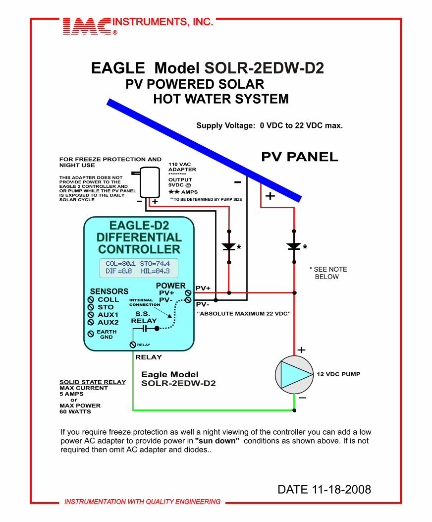
INSTRUMENTATION WITH QUALITY ENGINEERINGINSTRUMENTATION WITH QUALITY ENGINEERING
INSTRUMENTS INC INSTRUMENTS INC reg
PC Data-Port Adapter RS-232 SOLR-DA10
Connects directly to the EAGLE controller DATA-PORT and permits serial PC communication at 2400 BAUD rate non-isolated
Adapter has a 7 foot cable terminated with an RJ-45 plug
EAGLE ldquowebrdquo controller with a 2500 volt isolated PORT isrecommended for long-term or permanent installations Includes electronic circuits
inside the DB-9 connector housing
Immersion style4long with 14NPT fitting- SOLR-TS04
12NPT fitting- SOLR-TS248long with 14NPT fitting- SOLR-TS05
12NPT fitting- SOLR-TS25
Screw-in style SOLR-TS0312-NPT threaded plug
Bolt-on style SOLR-TS02
ACCESSORIES
THERMISTOR TEMPERATURE SENSORS-
ORATED TO 400 F
INSTRUMENTATION WITH QUALITY ENGINEERINGINSTRUMENTATION WITH QUALITY ENGINEERING
INSTRUMENTS INC INSTRUMENTS INC reg
DATE 11-18-2008
110 VACADAPTEROUTPUT 9VDC
AMPS-
++-
EAGLE Model PV POWERED SOLAR
HOT WATER SYSTEM
Supply Voltage 0 VDC to 22 VDC max
SOLR-2EDW-D2
12 VDC PUMP
SOLID STATE RELAYMAX CURRENT 5 AMPS or MAX POWER60 WATTS
FOR FREEZE PROTECTION ANDNIGHT USE
PV PANEL
ldquoABSOLUTE MAXIMUM 22 VDCrdquo
Eagle ModelSOLR-2EDW-D2
THIS ADAPTER DOES NOT PROVIDE POWER TO THE EAGLE 2 CONTROLLER ANDOR PUMP WHILE THE PV PANELIS EXPOSED TO THE DAILY SOLAR CYCLE
PV+
PV-
RELAY+
_
TO BE DETERMINED BY PUMP SIZE
If you require freeze protection as well a night viewing of the controller you can add a low power AC adapter to provide power in sun down conditions as shown above If is not required then omit AC adapter and diodes
SS RELAY AUX2
AUX1STOCOLL INTERNAL
CONNECTION
EARTH GND
RELAY
PV+PV-
POWERSENSORS
COL=801 STO=744DIF =80 HIL=843COL=801 STO=744DIF =80 HIL=843
EAGLE-D2DIFFERENTIALCONTROLLER
EAGLE-D2DIFFERENTIALCONTROLLER
SEE NOTE BELOW
INSTRUMENTATION WITH QUALITY ENGINEERINGINSTRUMENTATION WITH QUALITY ENGINEERING
INSTRUMENTS INC INSTRUMENTS INC reg
PC Data-Port Adapter RS-232 SOLR-DA10
Connects directly to the EAGLE controller DATA-PORT and permits serial PC communication at 2400 BAUD rate non-isolated
Adapter has a 7 foot cable terminated with an RJ-45 plug
EAGLE ldquowebrdquo controller with a 2500 volt isolated PORT isrecommended for long-term or permanent installations Includes electronic circuits
inside the DB-9 connector housing
Immersion style4long with 14NPT fitting- SOLR-TS04
12NPT fitting- SOLR-TS248long with 14NPT fitting- SOLR-TS05
12NPT fitting- SOLR-TS25
Screw-in style SOLR-TS0312-NPT threaded plug
Bolt-on style SOLR-TS02
ACCESSORIES
THERMISTOR TEMPERATURE SENSORS-
ORATED TO 400 F
INSTRUMENTATION WITH QUALITY ENGINEERINGINSTRUMENTATION WITH QUALITY ENGINEERING
INSTRUMENTS INC INSTRUMENTS INC reg
DATE 11-18-2008
110 VACADAPTEROUTPUT 9VDC
AMPS-
++-
EAGLE Model PV POWERED SOLAR
HOT WATER SYSTEM
Supply Voltage 0 VDC to 22 VDC max
SOLR-2EDW-D2
12 VDC PUMP
SOLID STATE RELAYMAX CURRENT 5 AMPS or MAX POWER60 WATTS
FOR FREEZE PROTECTION ANDNIGHT USE
PV PANEL
ldquoABSOLUTE MAXIMUM 22 VDCrdquo
Eagle ModelSOLR-2EDW-D2
THIS ADAPTER DOES NOT PROVIDE POWER TO THE EAGLE 2 CONTROLLER ANDOR PUMP WHILE THE PV PANELIS EXPOSED TO THE DAILY SOLAR CYCLE
PV+
PV-
RELAY+
_
TO BE DETERMINED BY PUMP SIZE
If you require freeze protection as well a night viewing of the controller you can add a low power AC adapter to provide power in sun down conditions as shown above If is not required then omit AC adapter and diodes
SS RELAY AUX2
AUX1STOCOLL INTERNAL
CONNECTION
EARTH GND
RELAY
PV+PV-
POWERSENSORS
COL=801 STO=744DIF =80 HIL=843COL=801 STO=744DIF =80 HIL=843
EAGLE-D2DIFFERENTIALCONTROLLER
EAGLE-D2DIFFERENTIALCONTROLLER
SEE NOTE BELOW
VER 11-18-08 PRINTED IN USAINSTRUMENTATION WITH QUALITY ENGINEERINGINSTRUMENTATION WITH QUALITY ENGINEERING
INSTRUMENTS INC INSTRUMENTS INC reg
COL=1741 STO= 1 10 4PKH =18 04 PKL= 6 0 1AX1=-105 AX2= 17 5 3PMP= O N UPL=ON
COL=1741 STO= 1 10 4PKH =18 04 PKL= 6 0 1AX1=-105 AX2= 17 5 3PMP= O N UPL=ON
ACTUAL SIZE DISPLAYwhen printed booklet size
ACTUAL SIZE DISPLAYwhen printed booklet size
IMPORTANT NOTICE
Do NOT attempt to connect any ETHERNET device or any other non-IMC devices to the RJ-45 DATA-PORT of any IMC CONTROLLER or accessory This will result in damage to the connected equipment Connect ONLY devices specifically designed by IMC Instruments to be connected to these ports
ACCESSORIES continued
LCD MASTER DIGITAL DISPLAY PANEL- SOLR-RD84 (very low power consumption) Displays temperature and status indication with 80 characters (4x20) 14rdquo high Supplied with a 3rsquo foot CAT-5 cable that connects directly to the EAGLE controller Data-PortHousing dimensions are 433rdquo (110mm) wide x 234rdquo (82mm) high x 173rdquo (44mm) deep
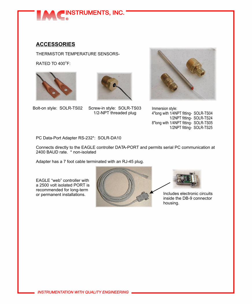
INSTRUMENTATION WITH QUALITY ENGINEERINGINSTRUMENTATION WITH QUALITY ENGINEERING
INSTRUMENTS INC INSTRUMENTS INC reg
PC Data-Port Adapter RS-232 SOLR-DA10
Connects directly to the EAGLE controller DATA-PORT and permits serial PC communication at 2400 BAUD rate non-isolated
Adapter has a 7 foot cable terminated with an RJ-45 plug
EAGLE ldquowebrdquo controller with a 2500 volt isolated PORT isrecommended for long-term or permanent installations Includes electronic circuits
inside the DB-9 connector housing
Immersion style4long with 14NPT fitting- SOLR-TS04
12NPT fitting- SOLR-TS248long with 14NPT fitting- SOLR-TS05
12NPT fitting- SOLR-TS25
Screw-in style SOLR-TS0312-NPT threaded plug
Bolt-on style SOLR-TS02
ACCESSORIES
THERMISTOR TEMPERATURE SENSORS-
ORATED TO 400 F
INSTRUMENTATION WITH QUALITY ENGINEERINGINSTRUMENTATION WITH QUALITY ENGINEERING
INSTRUMENTS INC INSTRUMENTS INC reg
DATE 11-18-2008
110 VACADAPTEROUTPUT 9VDC
AMPS-
++-
EAGLE Model PV POWERED SOLAR
HOT WATER SYSTEM
Supply Voltage 0 VDC to 22 VDC max
SOLR-2EDW-D2
12 VDC PUMP
SOLID STATE RELAYMAX CURRENT 5 AMPS or MAX POWER60 WATTS
FOR FREEZE PROTECTION ANDNIGHT USE
PV PANEL
ldquoABSOLUTE MAXIMUM 22 VDCrdquo
Eagle ModelSOLR-2EDW-D2
THIS ADAPTER DOES NOT PROVIDE POWER TO THE EAGLE 2 CONTROLLER ANDOR PUMP WHILE THE PV PANELIS EXPOSED TO THE DAILY SOLAR CYCLE
PV+
PV-
RELAY+
_
TO BE DETERMINED BY PUMP SIZE
If you require freeze protection as well a night viewing of the controller you can add a low power AC adapter to provide power in sun down conditions as shown above If is not required then omit AC adapter and diodes
SS RELAY AUX2
AUX1STOCOLL INTERNAL
CONNECTION
EARTH GND
RELAY
PV+PV-
POWERSENSORS
COL=801 STO=744DIF =80 HIL=843COL=801 STO=744DIF =80 HIL=843
EAGLE-D2DIFFERENTIALCONTROLLER
EAGLE-D2DIFFERENTIALCONTROLLER
SEE NOTE BELOW
VER 11-18-08 PRINTED IN USAINSTRUMENTATION WITH QUALITY ENGINEERINGINSTRUMENTATION WITH QUALITY ENGINEERING
INSTRUMENTS INC INSTRUMENTS INC reg
COL=1741 STO= 1 10 4PKH =18 04 PKL= 6 0 1AX1=-105 AX2= 17 5 3PMP= O N UPL=ON
COL=1741 STO= 1 10 4PKH =18 04 PKL= 6 0 1AX1=-105 AX2= 17 5 3PMP= O N UPL=ON
ACTUAL SIZE DISPLAYwhen printed booklet size
ACTUAL SIZE DISPLAYwhen printed booklet size
IMPORTANT NOTICE
Do NOT attempt to connect any ETHERNET device or any other non-IMC devices to the RJ-45 DATA-PORT of any IMC CONTROLLER or accessory This will result in damage to the connected equipment Connect ONLY devices specifically designed by IMC Instruments to be connected to these ports
ACCESSORIES continued
LCD MASTER DIGITAL DISPLAY PANEL- SOLR-RD84 (very low power consumption) Displays temperature and status indication with 80 characters (4x20) 14rdquo high Supplied with a 3rsquo foot CAT-5 cable that connects directly to the EAGLE controller Data-PortHousing dimensions are 433rdquo (110mm) wide x 234rdquo (82mm) high x 173rdquo (44mm) deep