Weaving of 3D fabrics: A Critical Appreciation
59
Textile Progress Vol. 41, No. 1, 2009, 1–58 Weaving of 3D fabrics: A critical appreciation of the developments N. Gokarneshan a∗ and R. Alagirusamy b a National Institute of Fashion Technology, Tirupur Exporter’s Association, Tirupur 641 606, India; b Department of Textile Technology, Indian Institute of Technology, New Delhi 110016, India (Received 28 January 2009; final version received 9 February 2009) The paper critically reviews the various developments that have taken place in the area of weaving 3D fabrics. Various methods have been evolved and each is unique in its own way. Each method is suited for specific end use applications. Thus, fabrics could be woven with different structures and profiles to fit specific requirements. The unique features of each method have been highlighted. The major differences between the 2D and 3D methods of weaving have been pointed out. 3D fabrics could be manufactured on the 2D conventional weaving machines with certain modifications. The 3D fabrics are basically intended for use in technical applications. Fabrics could be produced with special profiles and shapes to cater to specific applications. Methods have been evolved for producing 3D fabrics to be used as advanced composite preforms, by weaving on a conventional loom by modifying the shedding and take–up devices. Yet another interesting recent development is the utility of the 3D weaving concept to produce bifurcated vascular prosthesis. Keywords: profile; dual shedding; advanced preform; algorithm; dome; prosthesis 1. Introduction Over the years, a number of methods have been evolved in the manufacturing of three- dimensional (3D) woven fabrics. Many of the methods adopted deviate from the standard 3D weaving principle. The properties of the 3D fabrics differ according to the method of producing them. Thus, each method produces fabrics suitable for specific applications. Three-dimensional fabrics could be produced as non-interlaced or interlaced types. The earliest method has been noobing technique and the fabric so produced by the method is considered to be a non-woven fabric, even though produced on a loom. A number of methods have been developed which do not strictly conform to the 3D weaving principle, and fabric properties differ accordingly. Fabrics could accordingly be categorised as 3D woven 3D fabric and two-dimensional (2D) woven 3D fabric. A mono-directional shedding is used in 2D weaving and a dual-directional shedding is used in 3D weaving. One interesting aspect of the 3D weaving process is that it produces fabrics on a volumetric basis, whereas the 2D weaving process produces fabrics on an areal basis. Machine speed is not an important criterion, since quality of the material is of prime concern. It is essential to produce high quality in relatively low quantities. Each weaving method produces a fabric that would suit different end use applications. Newer methods have enabled weaving of preforms that are ∗ Corresponding author. Email: [email protected] ISSN 0040-5167 print/ISSN 1754-2278 online c 2009 The Textile Institute DOI: 10.1080/00405160902804239 http://www.informaworld.com
-
Upload
garmentlearner -
Category
Documents
-
view
53 -
download
1
description
The paper critically reviews the various developments that have taken place in the area of weaving 3D fabrics. Various methods have been evolved and each is unique in its own way. Each method is suited for specific end use applications. Thus, fabrics could be woven with different structures and profiles to fit specific requirements. The unique features of each method have been highlighted.
Transcript of Weaving of 3D fabrics: A Critical Appreciation
Textile ProgressVol. 41, No. 1, 2009, 1–58
Weaving of 3D fabrics: A critical appreciation of thedevelopments
N. Gokarneshana∗ and R. Alagirusamyb
aNational Institute of Fashion Technology, Tirupur Exporter’s Association, Tirupur641 606, India;bDepartment of Textile Technology, Indian Institute of Technology,
New Delhi 110016, India
(Received 28 January 2009; final version received 9 February 2009)
The paper critically reviews the various developments that have taken place in the areaof weaving 3D fabrics. Various methods have been evolved and each is unique in itsown way. Each method is suited for specific end use applications. Thus, fabrics couldbe woven with different structures and profiles to fit specific requirements. The uniquefeatures of each method have been highlighted. The major differences between the 2Dand 3D methods of weaving have been pointed out. 3D fabrics could be manufacturedon the 2D conventional weaving machines with certain modifications. The 3D fabricsare basically intended for use in technical applications. Fabrics could be produced withspecial profiles and shapes to cater to specific applications. Methods have been evolvedfor producing 3D fabrics to be used as advanced composite preforms, by weavingon a conventional loom by modifying the shedding and take–up devices. Yet anotherinteresting recent development is the utility of the 3D weaving concept to producebifurcated vascular prosthesis.
Keywords: profile; dual shedding; advanced preform; algorithm; dome; prosthesis
1. Introduction
Over the years, a number of methods have been evolved in the manufacturing of three-dimensional (3D) woven fabrics. Many of the methods adopted deviate from the standard3D weaving principle. The properties of the 3D fabrics differ according to the methodof producing them. Thus, each method produces fabrics suitable for specific applications.Three-dimensional fabrics could be produced as non-interlaced or interlaced types. Theearliest method has been noobing technique and the fabric so produced by the method isconsidered to be a non-woven fabric, even though produced on a loom. A number of methodshave been developed which do not strictly conform to the 3D weaving principle, and fabricproperties differ accordingly. Fabrics could accordingly be categorised as 3D woven 3Dfabric and two-dimensional (2D) woven 3D fabric. A mono-directional shedding is used in2D weaving and a dual-directional shedding is used in 3D weaving. One interesting aspectof the 3D weaving process is that it produces fabrics on a volumetric basis, whereas the2D weaving process produces fabrics on an areal basis. Machine speed is not an importantcriterion, since quality of the material is of prime concern. It is essential to produce highquality in relatively low quantities. Each weaving method produces a fabric that would suitdifferent end use applications. Newer methods have enabled weaving of preforms that are
∗Corresponding author. Email: [email protected]
ISSN 0040-5167 print/ISSN 1754-2278 onlinec© 2009 The Textile InstituteDOI: 10.1080/00405160902804239http://www.informaworld.com

2 N. Gokarneshan and R. Alagirusamy
found to be suitable for advanced textile composite applications. Also it has been possible tomanufacture preforms with varied profiles. The woven preforms compare well with thoseof knitted and non-woven ones. Three-dimensional fabrics have been produced on theconventional 2D weaving machine with modifications in certain loom mechanisms. Use ofcomputers has been made so as to produce complex 3D woven structures. Special yarns suchas those made from glass have been used to great advantage. Near net-shaped preforms havebeen produced. When 3D fabrics are used as preforms in composite applications, propertiessuch as high axial rigidity, flexibility, formability and stability are of prime importance.Very recently, 3D fabrics have been woven for use as vascular prosthesis, which has beendeveloped by using a simplified 3D weaving concept.
2. Three-dimensional fabric manufacturing process
Three-dimensional fabrics are basically produced for textile composite applications. Theconventional 2D weaving method is utilised in the production of interlaced 3D fabricwith two series of yarns, and non-interlaced 3D fabric with three series of yarns. Thoughthe interlaced 3D fabric is produced by the 2D weaving process, the production of non-interlaced 3D fabric cannot be considered as an actual 3D weaving process. The reasonfor this is that the 2D weaving method is intended to cause interlacement of two perpen-dicular series of yarns, but not three perpendicular series of yarns. A method has beendeveloped and this causes interlacement of three perpendicular series of yarns and cantherefore be considered as a ‘true’ 3D weaving process [1]. Though the method of pro-ducing non-interlaced 3D fabric is generally described as the 3D weaving process, it doesconform to the principle of the actual 3D weaving process in reality. Hence, clear-cut oper-ational features are to be highlighted so as to differentiate between the processes discussedherein.
2.1 Manufacturing of different types of fabrics by 2D weaving
In the case of 2D weaving, two sets of perpendicular yarns are interlaced, irrespective ofwhether it is woven as single- or multi-layer. Another set of yarns, known as pile or binderyarns, can be introduced in the direction of fabric thickness. Fabrics could be produced by2D techniques, with different sets of warp yarns in the ways mentioned below:
(1) By effective utilisation of warp and weft in single layer.(2) By the use of multi-layer warp and weft or multi-layer ground warp, binder warp and
weft.(3) Conventional 2D process can also produce pile fabrics by utilising three sets of yarns,
namely, single-layer ground warp, pile warp and weft.
2.1.1 Production of interlaced 3D fabric
The 3D fabric can be manufactured by adopting the conventional 2D weaving principle,by necessarily using a multi-layer warp. It is possible to produce interlacing type of 3Dfabrics such as warp interlock and weft interlock [2–5]. These fabrics are shown in Figure1. The various layers of the multi-layer warp could be interconnected to one another. In thecase of such 3D fabrics comprising two series of yarns, the multi-layer warp is displacedalong the direction of fabric thickness by means of shedding, and forms a shed in the width-wise direction of the fabric, so as to allow weaving principle to be known as ‘multi-layerweaving’.
Textile Progress 3
Figure 1. Interlaced 3D fabrics consisting of two series of yarns. (a) Weft interlock; (b) Warpinterlock (solid type); (c) Warp interlock (core or sandwich type).
2.1.2 Production of non-interlaced 3D fabric
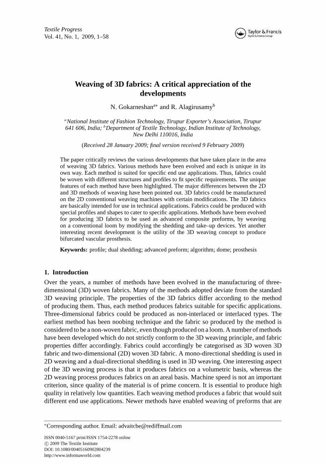
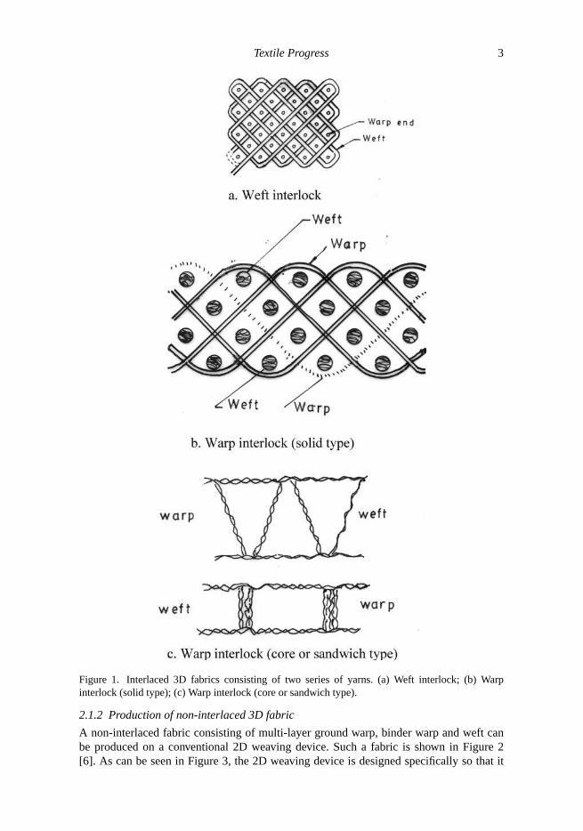
A non-interlaced fabric consisting of multi-layer ground warp, binder warp and weft canbe produced on a conventional 2D weaving device. Such a fabric is shown in Figure 2[6]. As can be seen in Figure 3, the 2D weaving device is designed specifically so that it
4 N. Gokarneshan and R. Alagirusamy
Figure 2. Non-interlaced 3D fabric (noobed) with three perpendicular sets of yarns.
Figure 3. Manufacture of non-interlaced 3D fabric (with three perpendicular sets of yarns) on aconventional 2D weaving machine.
deviates from the conventional 2D weaving concept. The shedding operation, which is themost important aspect of weaving, is altogether eliminated. A single heald frame is used forlaying the binder warp along the direction of fabric thickness to form the shed. The fillingyarn is inserted across the false shed, which is the gap between the uncrossed separatedlayers of the multi-layer warp. The binder warp binds the formed fabric in the direction ofthe fabric thickness; the weft binds the formed fabric along the direction of the fabric width.Interlacement does not take place between the three sets of yarns used. The woven structureso formed is held together by the bindings of two mutually perpendicular directions. Thus,the three series of yarns lie almost perpendicular to one another, without interlacement, inthe 3D fabric so formed. Therefore, in spite of using a modified 2D weaving device forproducing a non-interlaced 3D fabric, the manufacturing principle and the operation of themechanism cannot technically be considered as weaving.
2.2 Differentiation between 2D and actual 3D weaving processes
In the case of ‘simple’ interlaced 3D fabric, the multi-layered warp is interlaced withweft through formation of warp shed along the direction of fabric width, through theprocess of conventional 2D weaving. This is also considered as multi-layer weaving.Thus, this method is restricted in the design to displace the multi-layer warp yarns inthe fabric thickness direction only. Owing to this restriction, it is unable to interlacethe multi-layer warp yarns and the vertical set of weft yarns that are laid across thefabric thickness direction during the production of non-interlaced 3D fabric. Therefore,the conventional weaving method is unable to displace the multi-layer warp yarns in

Textile Progress 5
Figure 4. A completely interlaced 3D fabric.X, Y andZ – perpendicular sets of warp yarns.
the direction of fabric width in order to form sheds across the direction of fabric thick-ness. As a result, it cannot affect complete interlacement of three perpendicular series ofyarns.
A method has been developed [7] that causes interlacement of three perpendicularsets of yarns so as to form a completely interlaced 3D fabric, as shown in Figure 4. Thismethod conforms with the principle of weaving and thus deserves to be called a ‘true’3D weaving process, since it can cause interlacement of three series of yarns, namely,multi-layer warp yarns, vertical weft yarns, and weft. This true 3D weaving process ischaracterised by its ability to cause shedding of the multi-layer warp column-wise and row-wise (along the direction of fabric thickness and width) so as to interlace the multi-layerwarp with one series of horizontal weft and another series of vertical weft. This shed called‘dual direction’ shedding, proceeds in a successive manner but not simultaneously duringa weaving cycle. The integrity of such a structure arises due to the intense interlacementof three perpendicular series of yarns (Figures 4a and 4b). It is indeed logical to demarcatebetween 3D fabrics produced by a 2D weaving process as 2D woven 3D fabric and thoseproduced by a 3D weaving method as 3D woven 3D fabric.

6 N. Gokarneshan and R. Alagirusamy
2.3 Basic aspects of non-interlaced 3D fabric manufacturing process
Three-dimensional fabrics of the non-interlacing type (Figure 2) that could be produced byusing a modified type of 2D weaving device, can also be manufactured by using a multi-axial warp knitting machine [8], and also a special braiding device [8]. It is to be noted thatthe methods mentioned herein are deviations of the respective weaving principles used. Thenon-interlaced 3D fabric forming principle can be specifically described and characterised,just as any other fabric forming principle. The non-interlaced 3D fabric-forming processhas been utilised over a long period of time, without any specific name [9]. This method ischaracterised as a 3D weaving process probably due to its almost identical features with thecharacteristics of a weaving process and probably due to the fact that the different developeddevices [10–19] conform to the international patent classification system related to weaving[20]. However, the 3D fabric produced through this method is differently known such asorthogonal non-woven or non-interlaced or orthogonal 3D fabric, etc. [21–25]. Thus, akind of discrepancy exists between process and product, which creates ambiguities. Thus,the traditional definitions related to weaving in this aspect are incorrect and unsatisfactory[26]. Hence, a new specific definition is required in order to solve this problem of technicalambiguity. In this regard, a new definition is given after explaining the general operation ofthe non-interlaced 3D fabric-manufacturing method and related aspects.
The non-interlaced 3D fabric manufacturing method could be characterised as follows:
(1) It should be capable of assembling three series of yarns length-wise, without crimp,in an almost perpendicular orientation. It is to be noted that this method is unable tocombine two series of yarns to form a 2D fabric.
(2) It should have the ability to produce only non-interlaced 3D fabric by necessarilycombining three series of yarns by means of a method of binding. This does notinvolve weaving, knitting or braiding of the yarns used for the purpose.
(3) It should form a fabric conforming to the single-fabric system and self-supporting innature. The bonding should neither be of the thermal or adhesive type, and the fabricsystem should not be plied and stitched. The fabric should consist of yarns/filamentsbut not fibres.
The non-interlaced 3D fabric forming process is considerably simple and could beutilised to produce fabrics with solid and tubular profiles. In the case of simple solid fabricconstructions, the three series of yarns are placed like perpendicular planes, and in the case oftubular fabric constructions like cones and cylinders, the three series of yarns will be placedaxially, radially and circumferentially. It is to be noted that a 3D woven 3D fabric will havea network-like structure, whereas a non-interlaced 3D fabric will not have such a structure.
3. Classification of shedding systems
The shedding operation is the most crucial aspect of the weaving process, since it isfollowed by picking, and forms the basic operation of the weaving process. The 3D fabricforming process is identical to the weaving process in certain aspects. But even without theshedding operation, it has been considered as 3D weaving for many years. Considerabledevelopments relating to the 2D weaving process have not been given due consideration, incomparison with the different developments related to picking systems of unconventionalmachines. Developments in shuttleless weaving machines in recent years have paved theway for developing different shedding systems. It is interesting to note that the non-interlaced 3D weaving process did not originate in the textile industry, but was developedin the aerospace industry. This method has recently been characterised as a non-wovenprocess and is called ‘uni-axial noobing’ [27,28]. The 2D and 3D weaving processes could

Textile Progress 7
be basically differentiated by means of their shedding operation. They are characterised bymono- and dual-directional shedding operations, respectively [29,30].
The mono-directional shedding method has been in use over a long period of time, andconsists of reciprocatory and rotary types. The shed is formed by moving the warp yarnsalong the direction of the fabric thickness. Thus, the shed is formed in the fabric width-direction and enables picking with the filling yarn. Interlacement in 2D weaving takes placebetween two mutually perpendicular sets of yarns, i.e. either single- or multi-layer warp andweft, irrespective of whether a 2D, 2.5D or 3D fabric is produced. The 3D weaving processhas been characterised with the development of the dual direction shedding methods. Anew system of classification has been evolved, wherein seven different methods have beenidentified and presented herein [31]. The characteristics of the 3D weaving processes havebeen established with the development of dual directional shedding methods [32,33].
The new classification of the shedding methods is shown in Figure 5. It is based onthe mono- and dual-directional shedding methods. Each of these is further divided into itsrespective main types. There are seven different classes of shedding methods between these.
Classes of shedding
2D weaving Mono-directional shedding
3D weaving Dual directional shedding
(2)Multi Phase Wave shedding
(4)Multi Phase Wave Shedding
(6)Multi Phase simultaneous
Linear shedding
(7)Multi Phase
simultaneous Linear shedding
(8) Multiple Sequential Linear shedding
Rotary type Reciprocatory type Reciprocatory type
(1)Single Phase linear
Shedding
(3)Single Phase linear
SheddingLinear-linear Linear-angular
Figure 5. Classification of the shedding systems.
Rotary or reciprocatory shedding methods are used to displace the warp threads informing the shed. In the reciprocating type, the rotary shedding motion is converted intoreciprocatory motion, thereby requiring indirect control over the warp through the use ofhealds. In the case of the rotary type, healds are not used since the rotating shedding mech-anism controls the warp threads directly. The shed may be formed fully (simultaneously)or sectionally (gradually). Though only the reciprocating type of shedding is used in the3D weaving method, possibilities exist for the development of the rotary type of shedding.
8 N. Gokarneshan and R. Alagirusamy
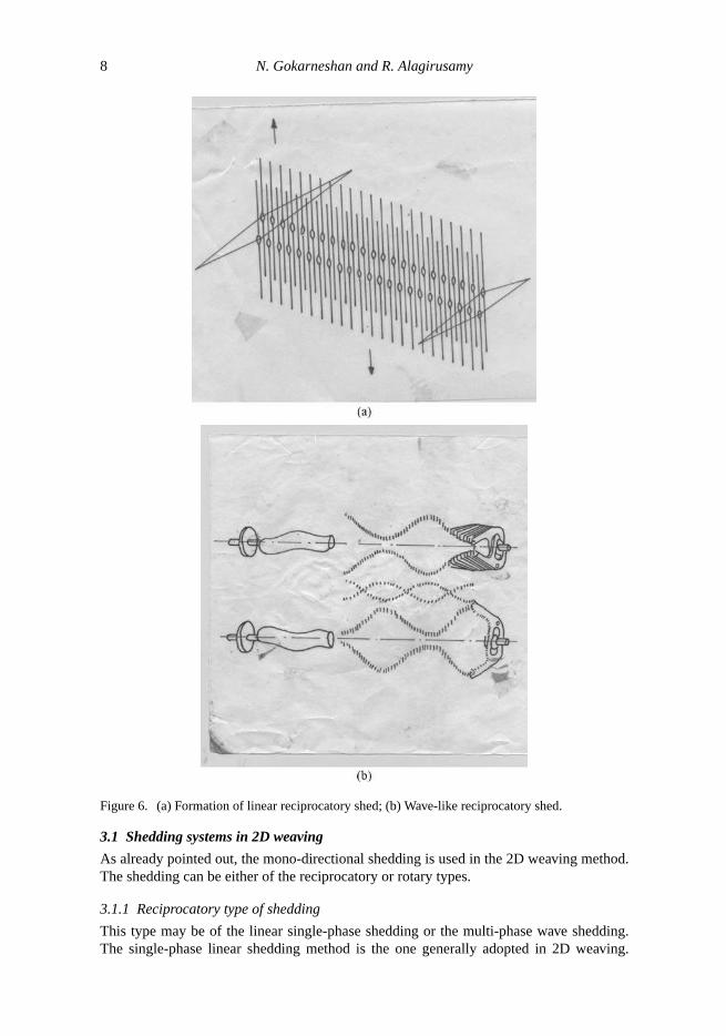
Figure 6. (a) Formation of linear reciprocatory shed; (b) Wave-like reciprocatory shed.
3.1 Shedding systems in 2D weaving
As already pointed out, the mono-directional shedding is used in the 2D weaving method.The shedding can be either of the reciprocatory or rotary types.
3.1.1 Reciprocatory type of shedding
This type may be of the linear single-phase shedding or the multi-phase wave shedding.The single-phase linear shedding method is the one generally adopted in 2D weaving.

Textile Progress 9
The shedding is accomplished through any of the mechanisms such as treadle, tappet/cam,dobby, and jacquard. This method can weave 2D fabrics such as bi-axial, tri-axial, andtetra-axial. It can also weave pile/terry 2.5D fabrics, angle-interlock, and plush 3D wovenfabrics. This system is a familiar one and is shown in Figure 6a.
The multi-phase wave shedding constitutes another type of the reciprocatory method ofshedding in 2D weaving. In this case, the shed is formed in sections successively in a phasedmanner (Figure 6b). Also, the shed moves in a wave-like pattern along the direction of weftinsertion. This kind of shedding uses healds that are in sections, and various techniqueshave been developed [34].
3.1.2 Rotary type of shedding
This method consists of three types of shedding systems, namely, the single-phase lin-ear shedding, the multi-phase wave shedding and the multiple sequential linear sheddingmechanisms. In the first type, rotating parts are used to form a complete linear shed, as theydirectly enable movement of the warp yarns, and thereby the use of healds is eliminated. Amethod of doing this is shown in Figure 7a [35]. It helps to produce a single fabric at a time.In another method that has been developed, more than one woven fabric can be producedsimultaneously [36], as shown in Figure 7b. The number of fabrics woven at a given timecorresponds to the number of working heads constituting the shedding mechanism.
Figure 7. Formation of linear rotary shed. (a) Rotating member pairs directly control the warp threadmovement; (b) Shedding mechanism directly lifts selected tape-like warp threads.

10 N. Gokarneshan and R. Alagirusamy
Figure 8. Multiple-phase wave rotary shedding.
Figure 9. Multiple sequential linear rotary shedding.
In the case of the multi-phase wave shedding, the complete shed is formed throughsuccessive sections of sheds continuously. The sections of sheds proceed in a wave-likemanner along the width-wise direction of the fabric. In this method too, as in the previousone, healds are not used. The complete shed lengths of successive sections are formed atthe same time when full length of the front-most shed is in the formation stage. Hence, ata given time, sections of more than one full shed length are formed successively to receivea corresponding number of weft picks. A method developed for the purpose [37] is shownin Figure 8.
In the next method, namely, the multiple sequential linear shedding, more than onesingle-phase linear shed is formed either successively or sequentially, and kept so for fillinginsertion. The method and its principle is illustrated in Figure 9. This method has beenfurther improved and developed [38], as shown in the figure. Subsequent developmentsinvolved a highly developed version of the method [39].
Textile Progress 11
3.2 Shedding system of 3D weaving
As compared with the 2D weaving wherein the mono-directional shedding is used, a 3Dweaving uses the dual-directional method of shedding. In the dual-directional sheddingmethod, only the reciprocatory type is available. This is of the following types, namely:
(1) Multiple simultaneous linear shedding of the linear–linear type.(2) Multiple simultaneous linear shedding of the linear–angular type.
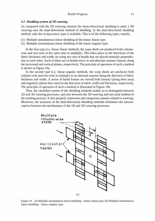
In the first type (i.e. linear–linear method), the warp sheds are produced both column-wise and row-wise at the same time in multiples. This takes place in the directions of thefabric thickness and width, by using two sets of healds that are placed mutually perpendic-ular to each other. Each of these set of healds move in and alternate manner linearly alongthe horizontal and vertical planes, respectively. The principle of operation of such a methodis shown in Figure 10a.
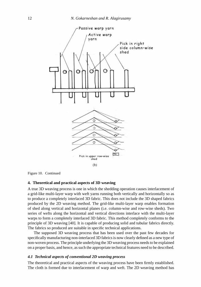
In the second type (i.e. linear–angular method), the warp sheds are produced bothcolumn-wise and row-wise in multiples in an alternate manner along the direction of fabricthickness and width. A series of heald frames are moved both linearly (along their axes)and angularly (about their axes) in the direction of fabric width and thickness, respectively.The principle of operation of such a method is illustrated in Figure 10b.
Thus, the classified system of the shedding methods enable us to distinguish between2D and 3D weaving processes, and also between the 3D weaving and uni-axial method ofthe noobing process. It also properly represents and categorises patents related to weaving.Moreover, the inclusion of the dual-directional shedding methods eliminates the miscon-ception between the mechanisms of the 2D and 3D weaving processes.
Figure 10. (a) Multiple simultaneous linear shedding – linear–linear type; (b) Multiple simultaneouslinear shedding – linear–angular type.
12 N. Gokarneshan and R. Alagirusamy
Figure 10. Continued
4. Theoretical and practical aspects of 3D weaving
A true 3D weaving process is one in which the shedding operation causes interlacement ofa grid-like multi-layer warp with weft yarns running both vertically and horizontally so asto produce a completely interlaced 3D fabric. This does not include the 3D shaped fabricsproduced by the 2D weaving method. The grid-like multi-layer warp enables formationof shed along vertical and horizontal planes (i.e. column-wise and row-wise sheds). Twoseries of wefts along the horizontal and vertical directions interlace with the multi-layerwarps to form a completely interlaced 3D fabric. This method completely conforms to theprinciple of 3D weaving [40]. It is capable of producing solid and tubular fabrics directly.The fabrics so produced are suitable in specific technical applications.
The supposed 3D weaving process that has been used over the past few decades forspecifically manufacturing non-interlaced 3D fabrics is now clearly defined as a new type ofnon-woven process. The principle underlying the 3D weaving process needs to be explainedon a proper basis, and hence, as such the appropriate technical features need to be described.
4.1 Technical aspects of conventional 2D weaving process
The theoretical and practical aspects of the weaving process have been firmly established.The cloth is formed due to interlacement of warp and weft. The 2D weaving method has

Textile Progress 13
been used for weaving with single-layer warp (such as those for producing several typesof bi-axial 2D fabrics) and multi-layer warp (such as those for producing 3D double/treblecloths, belting cloth etc.). It is interesting to note that the weaving process, more specifically,the shedding motion remains the same whether considering the production of 2D or 3Dfabric. The shedding involves cross-wise movement of the warp yarns along the directionof fabric thickness, and the warp yarns extend along the width direction of fabric, and theweft is inserted through the warp shed. Hence, it is not logical to consider the interlacementof a single-layer warp as 2D weaving and interlacement of multi-layer warp with weft as3D weaving. Therefore, the 2D weaving process can be considered as one where there isinterlacement between two mutually perpendicular sets of yarns. In other words, it is theinterlacement of one series of single-layer or multi-layer warp yarns with another series ofweft yarns. The fabrics so produced can be defined as 2D woven 2D fabric (single-layerwarp with weft) and 2D woven 3D fabric (multi-layer warp with weft).
It is important to note in the case of the 2D weaving method, the warp yarns, whethersingle- or multi-layered, lie side by side along the direction of the width of the fabric, asshown in Figures 11a and 11b. Only such an arrangement helps the warp yarns to movevertically without restriction. The movement is in one direction only and hence termed amono-directional shedding motion [31].
The 2D weaving method cannot use a multi-layer warp arranged in columns and rows(grid-like manner), as shown in Figure 12, since the mono-directional type of shedding
Figure 11. Warp arrangement in 2D weaving. (a) Single-layer warp and (b) multi-layer warp.
Figure 12. Multiple-layer warp (grid-like) arrangement.

14 N. Gokarneshan and R. Alagirusamy
cannot displace individual warp yarns of a column to form a shed. Hence, yarns of themulti-layer non-grid type can be used in the 2D weaving process. Such an arrangementenables production of 2D woven 3D fabric that incorporates the following features:
(1) The multi-layer warp move between upper and lower layers, and at the same timeoccupy the same longitudinal vertical axis along the direction of warp.
(2) Interlacement takes place between the multi-layer warp and weft yarns.
4.2 Manufacturing of 2.5D fabrics by conventional method
The 2D weaving method, besides producing 2D and 3D fabrics as explained above, canalso produce a 2.5D fabric (e.g. terry fabric). The method of production does not basicallydiffer from that of weaving 2D and 3D fabrics. It is indeed interesting to note that thecircular method of weaving is similar in its operation to that of producing a flat 2D fabric.Its 3D form does not make it a 3D fabric or 3D weaving process. So also, 3D shaped fabricssuch as spheroidally contoured, seamless 3D shells, and other types, cannot be technicallyconsidered as 3D weaving process [41–43]. In addition, the tri-axial and tetra-axial weavingmethods, are basically 2D weaving in principle [44–46].
4.3 Fundamental definitions
The different types of fabrics are considered to be 3D fabrics as they have a specificthickness besides their length and width. The following are given here:
(1) 2D fabric: it is one in which the component yarns (warp and weft) are placed in a singleplane.
(2) 2.5D fabric: it is one in which the component yarns are placed in two mutually perpen-dicular planes in relation to one another.
(3) 3D fabric: it is one in which the component yarns are placed in three mutually perpen-dicular planes in relation to one another.
A 3D fabric could not only consist of three sets of yarns, but two or even five series ofyarns.
4.4 Basic requirements for actual 3D weaving process
In order to make the 3D weaving operation effective, the following criteria needs to befulfilled:
(1) Multi-layer warps arranged in a grid-like manner.(2) Shedding is formed in rows and columns.(3) Two perpendicular series of wefts are inserted, of which one is in a horizontal direction
and the other is in a vertical direction.
It is to be noted that the 3D weaving process can be effective only by adopting thedual-directional shedding operation. This arises due to the fact the shedding is the mostcrucial operation in weaving. The next operations of picking and beat-up will be donecorrespondingly. In the case of the dual-directional shedding operation, the multi-layerwarp yarns will be moved in two directions, i.e. along the fabric thickness and width. Thisenables the formation of sheds in columns and rows.
Textile Progress 15
4.5 Shedding principle in 3D weaving method
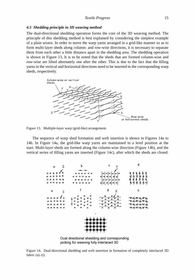
The dual-directional shedding operation forms the core of the 3D weaving method. Theprinciple of this shedding method is best explained by considering the simplest exampleof a plain weave. In order to move the warp yarns arranged in a grid-like manner so as toform multi-layer sheds along column- and row-wise directions, it is necessary to separatethem from each other a little distance apart in the shedding area. The shedding operationis shown in Figure 13. It is to be noted that the sheds that are formed column-wise androw-wise are lifted alternately one after the other. This is due to the fact that the fillingyarns in the vertical and horizontal directions need to be inserted in the corresponding warpsheds, respectively.
Figure 13. Multiple-layer warp (grid-like) arrangement.
The sequence of warp shed formation and weft insertion is shown in Figures 14a to14h. In Figure 14a, the grid-like warp yarns are maintained in a level position at thestart. Multi-layer sheds are formed along the column-wise direction (Figure 14b), and thevertical series of filling yarns are inserted (Figure 14c), after which the sheds are closed.
Figure 14. Dual-directional shedding and weft insertion in formation of completely interlaced 3Dfabric (a)–(i).

16 N. Gokarneshan and R. Alagirusamy
The interlacing structure so formed is shown in Figure 14d. In the next cycle of shedformations, the grid-like warp yarns that are in level form, multiple sheds in the directionof rows (Figure 14e), and the filling yarns are inserted in the horizontal direction (Figure14f), and the warp sheds are then closed. The interlacing structure so formed is shownin Figure 14g. Thus, the true 3D woven fabric formed at the end of the first weavingcycle is shown in Figure 14h. This kind of structure is known as the 3D woven 3D fabric(Figure 14i).
4.6 Practical significance of 3D process
The theoretical and practical aspects of the 3D weaving process enable better understandingof the same. The actual 3D weaving technology that has been developed is useful to ma-chinery manufacturers and manufacturers of technical textiles for meeting the requirementsof a variety of end use applications. The method is to be developed further.
The 3D weaving method has the following areas of applications:
(1) Filter fabrics, meshes used in cutting tools, etc.(2) Fabrics for ballistic protection.(3) Aquatic applications.(4) Medical uses such as ligaments and scaffolds.(5) High performance sports materials, such as shoe shells.(6) Advanced textile composites of flexible and rigid types.
One interesting aspect of the 3D weaving process is that it produces fabrics on avolumetric basis, whereas the 2D weaving process produces fabrics on an areal basis.Machine speed is not an important criterion, since quality of the material is of primeconcern. It is required to produce high value in relatively low quantities.
5. Noobing technique
A special type of non-woven 3D fabric manufacturing method has been designed in orderto combine three perpendicular sets of yarns without interlacing them, and this method hasbeen in vogue over the past few decades. This method is known as the noobing techniqueand is shown to differ from the 3D weaving process [28]. In this method, the operationof shedding considered to be crucial for weaving, is completely eliminated. There are twomethods of noobing, namely, uni-axial and multi-axial.
The uni-axial noobing has been specifically used for manufacturing preforms, and alsoin certain other technical applications.
5.1 Basic principle
The operating principle of the noobing technique is illustrated with the aid of the devicethat has been developed for the purpose (Figure 15). The two sets of weft carriers (Figures15a and 15b) are moved column-wise and row-wise, respectively, across the warp yarns.They follow a closed loop path. The fabric is thus formed in this way. After the two setsof weft yarns are laid, they are pushed to the fell of fabric, and the fabric formed is takenup by the device. Thus, one operating cycle of the noobing device is completed. It is to benoted that the three sets of yarns, one warp and two wefts, are almost perpendicular to eachother, and the yarns are uncrimped due to the non-interlacement.

Textile Progress 17
Figure 15. Production of noobed fabric on 2D weaving machine.
5.2 Mechanical description
The following constructional features are included with regard to the operating system ofthe noobing device:
(1) Means for arranging the warp yarns and disposing them suitably, and also ar-ranging all three series of yarns (one warp and two wefts) perpendicular to eachother.
(2) Method to provide traverse of binder weft yarn carriers of the horizontal and verticalweft yarns.
(3) Means for properly arranging the three series of yarns to form fabric.(4) Relating between the binder-yarn carriers traverse and integration of fabric.(5) Method of fixing the inserted horizontal and vertical weft yarns to the fell of cloth.(6) Means of take-up adopted for the fabric formed.

18 N. Gokarneshan and R. Alagirusamy
6. Computer-aided weaving of composite preforms
Woven fabric reinforced composites made of resins, have gained wide application andare continuing to grow since such structures are light weight combined with being highstrength. The reinforcing fabric has to be made into a preform (i.e. converted into shapeof the desired product) before impregnating it with suitable resin. The conversion of a 2Dfabric into a 3D preform is a tedious and expensive process. Hence, weaving machineshave been specifically designed for the purpose [47–50]. The draw back with these ma-chines is their high cost and specialised field of application. Hence, fabrics have beenwoven on conventional looms and have most of the required characteristics of a preform.Such a fabric can be converted into a preform by a rather simple operation of openingup or unfolding. When the geometrical configuration of the final product has been se-lected, the entire process of generating the required weaving instructions is transferredto a computer. A 2D fabric is made into a 3D fabric after removal from the loom andopening it up, since the fabric thickness matches its width. It is to be noted that the con-ventional looms can weave a wider variety of structures than unconventional weavingmachines.
In the case of a 2D or conventional loom, the manufacturing of a specific woven structurecan be divided into three major steps:
(1) Flattening process of the woven structure. This involves transferring the originaldesign onto the fabric that is sufficiently flat so as to be woven on a conventionalloom.
(2) In the flattened structure, different paths are chosen, and these are meant for thedirection of filling insertion. This is nothing but the selection of shuttle paths.
(3) In the final stage, the required weave pattern is obtained over the entire fabric structureand instructions are generated to the shedding motion and other related parts of theloom.
The method of flattening 3D preforms in order to enable them to be woven on con-ventional looms is indeed a very old one, but, has however, been restricted to very simplestructures. Recently, the same method has been utilised for weaving of more advancedstructures such as those of preforms made from fibre reinforced composites. The du-ration of designing preforms has been considerably reduced due to the utilisation ofcomputer software thus enabling us to solve several theoretical and practical problems.This has created new vistas in weaving research. With regard to the growth of fibre-reinforced composites, this area of research is expected to fetch significant economicalbenefits.
6.1 Flattening of 3D preforms
In the analysis considered here, the individual units of the preform are assumed to be straightlines whose thickness is ignored. Such a consideration enables solution of the geometricalproblems that arise during flattening. As the thickness of the fabric increases, the flatteningand folding up of the structure into individual parts presents practical difficulties. Hence,the flattening and folding of the structure can be considered for fabrics up to a certainthickness [51]. Various factors such as the type of weave, densities of warp and weft yarns,fibre and yarn properties decide the thickness limit of the fabric. In most of the cases, it isabout four–five layers in each side of the woven structure. Hence, it is possible to weave aconsiderable range of preforms using this method.

Textile Progress 19
6.1.1 Modelling and methodology
The structure considered here consists of several nodal points that are connected by straightlines known as sections. These lines represent the fabric elements. It is only after knowingthe horizontal and vertical co-ordinates of the nodes and the sections connecting them thatthe structure can be completely defined. Thus, it is necessary to know the co-ordinates ofthe nodes as well as the location of the sections.
Different methods are available to flatten a 3D textile preform into a 2D shape. Asthe fabric is flexible, it can be extended, bent and sheared. To begin with, considering thetheory of flattening, the sections of the woven structure are assumed to be rigid bodies.This implies that the sections of the structure have constant length and are kept straightduring the flattening or deformation process. Also, the changes in the orientation of eachsection can occur only at a node. Thus, the structure is first treated as a rigid mechanismand is supposed to attain the characteristic of textile material when the folding of theindividual sections is required. The mechanical approach is suitable for structures havingorientation in vertical and horizontal directions, and most of the preforms fall under thiscategory.
When the flattening process in which the horizontal and vertical directions are appliedto fabrics, the warp becomes the vertical direction and the weft becomes the horizontaldirection. Horizontal lines are drawn through all nodes where two or more sections meet andthese are called baselines. They may be of real or hypothetical types. When a hypotheticalbaseline crosses a section, a new node is formed. Sections that connect neighbouringbaselines are known as connectors. When flattening occurs, the connectors are deformedto an extent that they involve a simple rotation or a rotation combined with folding. Theprocess of flattening involves merging of all base lines with the horizontal axis. A numberof methods are available for doing this. The highest baseline is merged with the next oneand so on.
6.1.2 Development of software design
The software architecture has been developed by adopting the following steps:
(1) Reading in of the database.(2) Discretisation of the structure.(3) Identification of baseline and connectors.(4) Checking the length and orientation of the connectors.(5) Selection of the driver and direction of rotation.(6) Finding the additional nodes created by folding.(7) Merging all the baselines.
The complete system of flattening and the architecture of the software are shown inFigures 16 and 17. The numbers 1,2,3 and 4 represent the different components of theprogramme structure.
The entire structure is converted into a straight line by complete flattening. Hence,if the flattened structure is accurately presented, it would become impossible to identifyindividual sections on the monitor screen. Therefore, the flattened structure has been shownin a slightly irregular way in which all the horizontal coordinates are correct but the verticalcoordinates, instead of being zero, have a small finite value.

20 N. Gokarneshan and R. Alagirusamy
3D structure designing
3D geometry data transferring ……………………(1)
3D structure flattening …………………………….(2)
Shuttle paths optimisation …………………………. (3)
3D net shape structure weave pattern generation ……(4)
Machine code translation
Figure 16. System structure.
6.2 Option for selection of optimal flattening
Based on the size and nature of the preform, the flattening could be achieved in a numberof ways and hence it is necessary to select only optimal ones. The criteria for optimumflattening are dependent on the constraints of imposition by textile and machine parameters.These form an important part of the actual programme that has been developed and theselection of the optimum flattening procedure is done by the computer. The constraintsimposed are the loom width, maximum number of layers, and edge position of sections.The technology is versatile since a variety of target structures can be produced from theflattened structure.
Thus, the developed software enables conversion of true 3D preform designs into asubstantially 2D form that could be woven on a conventional weaving machine. The focushas been on the geometrical problems involved in weaving 3D preforms in 2D form. Furtherwork is required to provide an input of physical properties so as to define more clearly thecapabilities and limitations of the resulting CAD/CAM system.

Textile Progress 21
Judging the extent of deformation
Specify drivers of each level
Go to the level and rotate driver
Add the necessary nodes to the connectors
Displace deformation base for higher deformation levels
If there exist next level of deformation
Select practically possible flattening solutions
Figure 17. Flattening software architecture.
6.3 Analysis of flattened structure features
The path of the shuttle is not deviated from during the weaving process. Hence, anystructure can be produced by varying the position of the warp in relation to a new weft bythe shedding motion. In the case of computer analysis, however, the opposite is true. Thewarp ends remain in the given position within the flattened structure and the shuttle path isvaried. The flattened structure is the same as in the previous case. A certain combinationof shuttle paths is necessary for weaving the preform. A weave repeat in the weft directionwill only exist if two or more repeats of the same structure are woven side by side, but thispossibility has not been considered here [52].
6.3.1 Fundamental concept of flattened structures
The principle of the flattening can be explained with reference to the selection of shuttlepaths for the preform. The preform is in the form of a square that has been divided intofour equal parts. The structure considered consists of three baselines and two levels of

22 N. Gokarneshan and R. Alagirusamy
deformation and on both levels all connectors are parallel to each other so that all of themcan remain straight and retain their original length after flattening. There are a number ofnodes and sections in the structure. The nodes could be connected in different ways.
6.3.2 Analysis of weft insertion paths
In the case of shuttle looms, the weft is inserted from left to right, and back and forth. Forgenerations of weaving instructions, it is assumed that the weft is inserted from left to right.Hence, the node at the left side of the preform is considered as the starting node and thenode at the right is considered as the end node. During this point, the shuttle path is its paththrough the preform from left to right on one journey only. From the foregoing discussion, itis evident that a single-shuttle path cannot cater to the entire section of the structure. Hence,it is necessary to determine how many different shuttle paths are practically necessary.
Though the shuttle traverses the entire loom width, the start node of a shuttle path is thatwhere the weft starts to interlace with the warp, and the end node is that where interlacingends. The first step in analysing the features of the flattened structure is to find all thepossible shuttle paths that commence at a section start node that is not an end node, andwhich finish at a section end node which is not a start node.
The following criteria have to be fulfilled in choosing the combination of shuttle pathsthat are included in the repeat of the weave:
(1) Supplying weft to all sections.(2) Selecting the best shuttle path combination.(3) Shuttle path direction and sequence.(4) Creating the desired weft density in all sections.
6.3.3 Generation of weaving instructions
This is concerned with the manner of interlacement of the warp with the weft microstructure.In this regard, each of the shuttle paths must be considered as a group of shuttle paths inwhich the number of paths in the groups are determined by the repeat of the weave selected.The software so selected involves the following stages:
(1) Selection of the weave.(2) The repeat of the shuttle path is adjusted according to the weave repeat, if required.(3) The programmes for the micro and macrostructure are linked so as to form the detailed
weaving instructions.
The software-developed links for the micro and macrostructure is based on the generalprinciples of weave design and leads to the generation of complete weaving instructions.Such instructions are being used in weaving of many types of preforms.
6.4 Generation and weaving of a 3D net-shaped preform
Preforms have been woven with constant cross-section along the warp direction. Thesestructures can be completely identified by their cross-section, which is perpendicular to thewarp direction. The term ‘structure’ refers to the cross-section of the structure. It comprisesof a network of points called nodes, connected by lines known as sections. The weavepattern and weaving instructions can be generated based on the analysis discussed in theprevious sections. A specific structure has been described [53]. However, the principleinvolved in the analysis could be extended to other preforms with constant cross-section.

Textile Progress 23
6.4.1 The configuration of a flattened preform
The target structure, as well as the flattened structure, is shown in Figures 18 and 19. Thetarget structure comprises of 10 nodes and 11 sections. The flattening process causes thestructure to be folded into two sections, thereby resulting in two extra nodes and sectionseach. The flattened structure thus has 13 sections. The values of the horizontal as well as thevertical co-ordinates are stored in the software. For the sake of analysis, vertical lines aredrawn through all nodes and the spaces between these lines are referred to as areas. In order
Figure 18. The target structure.
Figure 19. The flattened structure.
24 N. Gokarneshan and R. Alagirusamy
to generate the weaving instructions, the structure has to be divided into discrete areas,since the weave pattern within each area remains constant. However, the weave patternalters between areas. This is due to the fact that the number of sections within a particulararea normally alters. In addition to knowing which sections are included in a particulararea, the relative positions they occupy with other sections also needs to be known. Hence,the analysis requires the division of each area into discrete levels. When a particular pickis inserted into a particular level in a particular area, all warp threads in higher levels mustbe lifted. The two main parameters relating to the microstructure of the preform are thebasic weave such as plain, twill, satin, etc. and the number of fabric layers. Preforms arenormally woven as multi-layer fabrics with three or four fabric layers. Multi-layer fabricscan have different types of constructions. The warp yarns of a layer interlace only withweft of the same layer. However, the layers are bound together at intervals that are largerthan the basic weave repeat, either by special binder yarn or by a local modification of theweave. When a specific warp yarn in a particular area is allocated to a particular level anda particular layer and has a particular value ofn within the weave repeat, its position (topor bottom shed) at a particular pick is completely defined.
6.4.2 Related terminologies
In order to better understand the discussion in previous sections, the following definitionswill prove useful:
Area: It is the part of the flattened preform between two adjacent vertical lines aftersuch lines have been drawn through all nodes.
Section:It is the fabric connecting two nodes.Single-layer fabric:It is a conventional fabric consisting of one layer of warp and one
layer of weft.Multi-layer fabric: It is a fabric with two or more single-layer fabric layers connected to
each other at binding points whose distance from each other in the warp and weft directionsis substantially greater than the basic weave repeat. The layers are numbered consecutivelyfrom top to bottom. A section situated within more than one area can have different levelnumbers in different areas.
Level: It is all or part of a section situated within one area. The levels are numberedconsecutively from top to bottom. A section located within more than one area can havedifferent level numbers in different areas.
Basic weave pattern:It is the weave pattern used in each level and layer.Weave pattern:It is the over-all interlacing repeat in the flattened structure.Basic warp repeat number:It is the number of warp threads in the basic weave repeat.Warp repeat number:It is the number of warp ends included in the over-all weave
repeat.
6.4.3 Warp thread arrangement
All the warp yarns are situated in one plane and are numbered consecutively from left toright, so that each end is identified by a number. The purpose of the warp arrangement isto allocate to each warp end its position within the micro and macrostructure. The positionwithin the microstructure is expressed in terms of the value of consecutive numbers of eachwarp end in basic weave repeat, which determines the position within the basic weave andthe value of the consecutive number of each layer within a level.
Textile Progress 25
The number of times the area weave repeat is actually repeated within the particulararea depends on the desired size of that area. The value of the number of area weave repeatswithin an area is one of the parameters that decides the value of the weave repeat numberfor the whole structure. It is to be noted that the number of structures woven side by sideis irrelevant in relation to the overall weave pattern. To generate the weave pattern, thesoftware requires a quantitative input concerning the location of the individual warp endsin a particular layer and a particular level. A 2D array is set up to store the information aboutthe warp end arrangement in the flattened structure, and is used in further computations.
6.4.4 Algorithm for calculation of yarn interlacing sequence
The algorithm has been developed in the following stages:
(1) Areas in which the weft picks commence and terminate.(2) Level position of shuttle path in each area.(3) The yarn interlacing sequence.
In order to identify a shuttle path’s commencement and ending zone, the computerhas been programmed to compare the horizontal co-ordinates at the start node of the firstsection and the horizontal co-ordinate of the end node of the of the last section of a path.With regard to the weaving, the weft yarn interlaces with the warp yarn a specific area toanother. In the other areas, the pick is only laid above the warp ends without interlacing.When the shuttle flies to the opposite direction at the next pick, the weft laid on top of thewarp ends of the non-interlacing areas is taken back.
For determining the level that a specific path traverses a specific area, it is primarilyrequired to take into account the sections covered by that path and then to determine thelevel of these sections in their respective areas. A series of procedures are followed by thesoftware in carrying out the analysis. On the basis of this path-level allocation, each shuttleand each shuttle path can be followed from start to end and placed in the appropriate levelin each area.
With regard to the yarn interlacing sequence, the number of shuttle paths in the weaverepeat and the sequence of shuttle paths are to be considered.
The final weaving instructions are taken from a point-paper design that is stored in adisk and can either be used for cutting the cards of a jacquard machine or be fed directly toan electronic jacquard. The entire information pertaining is available in the form of differentarrays, which consists of the information about the shuttle paths, the warp arrangement,the basic weave, the number of layers, etc. Primarily, the weaving instruction for a specificweft pick is restricted to the interlacement with the warp threads in the level and layerwhere that pick is inserted. Then the warp ends of various layers and corresponding levelsare considered in the method explained previously.
7. Weaving of advanced composite preforms
In the case of preforms used in advanced composite materials, the integrity of the structureis considered to be the main criteria, as the reinforcements made out of these become acrucial factor in deciding the mechanical characteristics of the composites. Hence, textilereinforcements have found varied applications in composites owing to their adaptability,which enables them to meet a wide range of reinforcing requirements.
Textile reinforced structures can be manufactured by different methods, such as thosemade from chopped fibres, filament yarns, simple fabrics and advanced fabrics [54]. The
26 N. Gokarneshan and R. Alagirusamy
3D textile reinforcements can be made by weaving, knitting, braiding and stitching [55].The 3D woven fabrics are superior to their 2D counterpart with respect to interlaminarand through-thickness characteristics due to the integrity in their structure, which arisesdue to perpendicular or angular constructions. Various methods of weaving are used tomanufacture 3D preforms with different structures. Angular interlock and perpendicularmulti-layer fabrics could be woven by using the multi-warp weaving methods. Other typesof woven preforms, such as those with cylindrical profiles, can be woven on looms speciallydesigned for the purpose [56–58].
7.1 Available methods
Non-crimped types of 3D fabrics have been produced by the warp- and weft-knittingmethods, wherein the fibre tufts are made to lie flat and then straightened and completelystretched, followed by knitting using fine filamental yarns, so as to keep the tows in position.They can be made into either single- or multi-layered structures, with each layer havinga particular orientation of fibres. Three-dimensional preforms are also produced througha braiding technique using different mechanisms [59–61]. They are also produced by astitching technique, which is simple and economical. The fabrics are bound by chain orinterlock stitching methods. Three-dimensional structures of complex shapes are not easyto produce economically, and very few machines have been developed at commercial level.The multi-axial warp knit and the structural core lamination techniques are effective in thisregard. The structures so produced, however, do not conform to the complex 3D structure.
7.2 Underlying concept
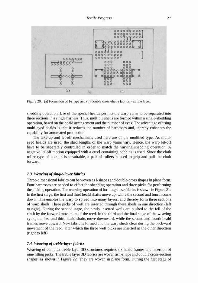
Three-dimensional woven fabrics of the I-shape and double cross-sectional shapes havebeen woven on a conventional loom by modifying its mechanisms [62]. Since the techniqueis simple owing to the simplicity of the weaving mechanisms, it is likely to suit automatedmanufacturing. The interlacement of the warp and weft yarns is done in the usual way usingthe primary and secondary motions [63]. The warp yarns have to be placed as a flat sheetform, as producing 3D fabrics of almost net-shape with I-shape and double-cross shapes isnot easy on a loom. The schematic diagrams of the fabrics of the I-shape and double-crossshapes are shown in Figures 20a and 20b. The warp yarns are arranged into three sectionsby using healds with many eyelets or openings, which enable formation of the main frameand flanges of the fabric. One series of warp yarns move between adjacent two sectionsto form the joint of the main frame and the flanges. The typical specifications of the 3Dfabrics woven are given below:
Type of fabric – Single layer (I and double-cross shapes)Type of material – CarbonWarp thread density – 2.8 ends/cmWeft thread density – 3.5 picks/cmType of fabric – Treble layerWarp thread density – 3.1 ends/cmWeft thread density – 4.3 picks/cm.
As already mentioned, more harnesses are needed to control the shedding operation forproducing complex weave patterns. Accordingly, the warp yarns are separated into threesections so as to produce the plane type of I-shape and double-cross woven structures.Special healds with many eyelets are used to separate the warp yarns in order to effect the
Textile Progress 27
Figure 20. (a) Formation of I-shape and (b) double cross-shape fabrics – single layer.
shedding operation. Use of the special healds permits the warp yarns to be separated intothree sections in a single harness. Thus, multiple sheds are formed within a single-sheddingoperation, based on the heald arrangement and the number of eyes. The advantage of usingmulti-eyed healds is that it reduces the number of harnesses and, thereby enhances thecapability for automated production.
The take-up and let-off mechanisms used here are of the modified type. As multi-eyed healds are used, the shed lengths of the warp yarns vary. Hence, the warp let-offhave to be separately controlled in order to match the varying shedding operation. Anegative let-off motion equipped with a creel containing bobbins is used. Since the clothroller type of take-up is unsuitable, a pair of rollers is used to grip and pull the clothforward.
7.3 Weaving of single-layer fabrics
Three-dimensional fabrics can be woven as I-shapes and double-cross shapes in plane form.Four harnesses are needed to effect the shedding operation and three picks for performingthe picking operation. The weaving operation of forming these fabrics is shown in Figure 21.In the first stage, the first and third heald shafts move up, while the second and fourth comedown. This enables the warp to spread into many layers, and thereby form three sectionsof warp sheds. Three picks of weft are inserted through these sheds in one direction (leftto right). During the second stage, the newly inserted wefts are pushed to the fell of thecloth by the forward movement of the reed. In the third and the final stage of the weavingcycle, the first and third heald shafts move downward, while the second and fourth healdframes move upward. New fabric is formed and the warp sheds clear during the backwardmovement of the reed, after which the three weft picks are inserted in the other direction(right to left).
7.4 Weaving of treble-layer fabrics
Weaving of complex treble layer 3D structures requires six heald frames and insertion ofnine filling picks. The treble layer 3D fabrics are woven as I-shape and double cross-sectionshapes, as shown in Figure 22. They are woven in plane form. During the first stage of

28 N. Gokarneshan and R. Alagirusamy
Figure 21. Weaving cycle of single-layer I-shape and double cross-shaped fabrics.
the weaving cycle, in the case of weaving I-shaped fabrics, the heald frames 1,3,4,5 and6 move upward, while heald frame 2 moves downward. In the case of weaving double-cross shaped fabrics, the heald frames 1,3 and 4 move upward, while the heald frames2,5 and 6 move downward. The warp yarns are thus divided into many layers, and henceform nine open warp sheds. Subsequently, nine filling picks are inserted from the left toright side of the loom. During the second stage of the weaving cycle, the reed pushes thejust inserted picks of weft to the fell of the cloth. In the final stage, the heald shafts shiftin the opposite direction, and thus the new fabric is formed. The warp sheds open duringthe backward motion of the reed. The filling picks are now inserted from the right tothe left hand side of the loom. The warp yarns in each section move to and fro betweenadjacent sections, and thus form an interlacing structure, which is a joint of the web andflanges.
7.5 Technical aspects of woven preforms
Considerable developments have taken place in the manufacturing of 3D woven preformsand this has led to the production of preforms with fibres oriented in different directions[64]. Table 1 gives relative description of the various preforming techniques regardingthe direction of yarn and fabric manufacturing principles. Two-dimensional woven textilestructures are generally formed into shape by moulding or stitching. They have goodin-plane properties and drapability. Two-dimensional preforms are suited for large areacoverage and extensive databases. Three-dimensional textile preforms are shaped into net-shaped thicker structures [65]. The 3D woven preforms have innumerable advantages,such as, very good drapability, ability to form into complex shapes without any gap andeconomical cost of manufacturing. They also have moderate in-plane and out of planeproperties. The simplest structure (plain) has good stability and porosity. However, thedrawback with this structure is its poor drapability and also higher levels of fibre crimp,

Textile Progress 29
Figure 22. Weaving cycle of treble layer I-shape and double cross-shaped fabrics.
which results in low mechanical properties in comparison with other weaves. The plainstructure gives higher crimp with thicker fibres, and therefore cannot be used for heavierfabrics. Twilled fabrics result in better drapability than plain ones due to the floating ofthe warp ends over two or more filling picks in a regular order. Also, the twilled structurehas a smoother surface and slightly better mechanical properties due to reduced crimp.The stability of the structure is only slightly reduced. Satin weaves are given even lower

30 N. Gokarneshan and R. Alagirusamy
Table 1. Comparison of different techniques of fabric production [64].
Parameter Direction of yarn feed Principle of fabric production
Knitting One (0◦/90◦) Interlooping (by drawing loops of yarns overprevious loops)
Weaving Two (0◦/90◦) Interlacing (by selective insertion of 90◦ yarns into 0◦
yarn system)Non-woven Three or more (orthogonal) Mutual fibre placementBraiding One (machine direction) Intertwining (position displacement)
crimp due to lesser intersections and hence have better mechanical properties compared totwill weaves. Matt weave is an extension of plain weave and two or more warp yarns floatover corresponding weft yarns. Hence, this weave is flatter than the plain weave due toless crimp. Though the former one exhibits higher strength than the latter, it shows poorerstability. Matt weaves are normally used for heavier fabrics constructed with thicker yarnsso as to reduce crimping. Leno weaves can give better stability using coarse yarn counts.However, since these weaves have an open structure and are not suitable for compositepreforms, they are used in combination with other weaves. Tri-axial weaves exhibit highlevels of isotropy and dimensional stability even at low fibre volume fraction [65,66]. Thecharacteristics of woven preforms are shown in Table 2.
Weaving is extensively used in the composite industry, as it produces the vast majorityof single layer, broad cloth fabric, which can be used as reinforcement. The poor impactperformance reduces in-plane shear properties, and the poor delamination resistance of suchstructures has led to the use of stitching techniques. In addition to weave crimp, stitchingis often considered a factor that reduces the mechanical efficiency of reinforcing fibres[67]. With some modifications, the standard industry machines can be used to manufactureflat, multi-layer fabrics of a wide variety of structures that have a highly improved impactperformance [68]. Multi-axial 3D weaving apparatus has also been reported. Bias yarnssandwiched between weft yarns and the resulting assemblies bound together by warp yarnshave produced unique structures. However, the main disadvantage of these multi-layerfabrics is that the standard looms cannot produce fabric that contains in-plane yarns atangles other than 0
◦and 90◦. This results in structures having very low shear and torsion
properties, thereby making them unsuitable in many aircraft structures where materialswith anisotropic properties are required. To overcome this problem, a great deal of efforthas been made for the development of looms that can produce fabric with± 45◦ [69].
Table 2. Comparison of the characteristics of woven preforms [64].
Type of weave of the preform
Characteristic Plain Twill Satin Basket Leno Mock leno
Drape B D E C E BCrimp B C E B E BStability D C B B A EPorosity C D E B A CBalance D D B D B DSmoothness B C E B A B
Note:A: Very poor; B: Poor; C: Good; D: Very good; E: Excellent.

Textile Progress 31
Multi-axial multi-layer 3D preforms have been produced by special weaving techniquessuch as tri-axial weaving, lappet weaving and pile weaving [67, 69–71] as shown in Table 3.In lappet weaving, surplus threads are introduced to develop isolated design motifs on anopen weave background. Ordinary weaving machines can be attached with a lappet systemsuitable for producing integrally woven multi-axial multi-layered preform structures forcomposites. The surplus yarns can be made to run at any angle between 0◦ and 90◦. The useof a jacquard shedding mechanism to manufacture multi-layer textile preforms has beendescribed in a patent [72,73], which explains a method to develop stress oriented T-shapedpreforms for composites.
The typical examples of 3D woven fabrics are simple interlock, orthogonal and com-plex shaped structures [74,75]. Different multi-layer 3D woven structures and multi-axialpile fabrics are shown in Figures 23 and 24, respectively. Using the multi-warp weavingmethod, various fibre structures can be developed, including solid orthogonal panels, vari-able thickness solid panels and core or truss like structures. Orthogonal cross-lapped fabricscan be formed by the placement of yarns at right angles to each other, typically in eitherrectangular or cylindrical spaces. There is no interlacing or other form of entanglementto hold the structure. Yarn is alternately laid between the edges in alternating orthogonaldirections to create a thick structure. Table 3 shows comparisons between some multi-axialweaving techniques.
7.6 Characterisation of woven preforms
When preforms are to be used in composite applications, properties such as high axial rigid-ity, flexibility, formability and stability are of prime importance. The important propertiesof woven preforms are shown in Table 4.
Figure 23. Types of multi-layer 3D woven structures. (a) Multi-layer 3D weave; (b) Change of angle;(c) Angle-interlock; (d) Variable thickness panel; (e) Near net-shaped preform.

32 N. Gokarneshan and R. Alagirusamy
Table 3. Comparison among different multi-axial weaving techniques [69].
Bias fibre Uniformity of bias Through-the-thicknessplacement fibre layers reinforcement Multiple layers
Rapier No Yes YesLappet Yes No NoScrew shaft No Yes YesSplit reed Yes Yes YesGuide block Yes Yes YesBobbin (polar) Yes Yes Yes
Figure 24. Pile interlacing patterns. (a) V-interlacing; (b) W-interlacing.
When designing the preforms, their geometrical properties are to be considered, asit would enable us to predict the resistance of preforms to mechanical deformation suchas initial extension, bending and shear in terms of resistance to deformation of individualfibres. It also gives information about the maximum packing that can be achieved in a fabric.
Textile preforms are subjected to a wide range of complex deformations during man-ufacturing of composites. Some serious problems have been observed during composite
Textile Progress 33
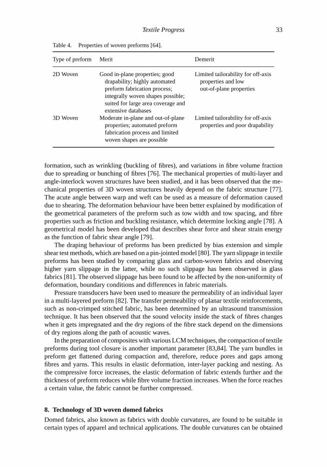
Table 4. Properties of woven preforms [64].
Type of preform Merit Demerit
2D Woven Good in-plane properties; gooddrapability; highly automatedpreform fabrication process;integrally woven shapes possible;suited for large area coverage andextensive databases
Limited tailorability for off-axisproperties and lowout-of-plane properties
3D Woven Moderate in-plane and out-of-planeproperties; automated preformfabrication process and limitedwoven shapes are possible
Limited tailorability for off-axisproperties and poor drapability
formation, such as wrinkling (buckling of fibres), and variations in fibre volume fractiondue to spreading or bunching of fibres [76]. The mechanical properties of multi-layer andangle-interlock woven structures have been studied, and it has been observed that the me-chanical properties of 3D woven structures heavily depend on the fabric structure [77].The acute angle between warp and weft can be used as a measure of deformation causeddue to shearing. The deformation behaviour have been better explained by modification ofthe geometrical parameters of the preform such as tow width and tow spacing, and fibreproperties such as friction and buckling resistance, which determine locking angle [78]. Ageometrical model has been developed that describes shear force and shear strain energyas the function of fabric shear angle [79].
The draping behaviour of preforms has been predicted by bias extension and simpleshear test methods, which are based on a pin-jointed model [80]. The yarn slippage in textilepreforms has been studied by comparing glass and carbon-woven fabrics and observinghigher yarn slippage in the latter, while no such slippage has been observed in glassfabrics [81]. The observed slippage has been found to be affected by the non-uniformity ofdeformation, boundary conditions and differences in fabric materials.
Pressure transducers have been used to measure the permeability of an individual layerin a multi-layered preform [82]. The transfer permeability of planar textile reinforcements,such as non-crimped stitched fabric, has been determined by an ultrasound transmissiontechnique. It has been observed that the sound velocity inside the stack of fibres changeswhen it gets impregnated and the dry regions of the fibre stack depend on the dimensionsof dry regions along the path of acoustic waves.
In the preparation of composites with various LCM techniques, the compaction of textilepreforms during tool closure is another important parameter [83,84]. The yarn bundles inpreform get flattened during compaction and, therefore, reduce pores and gaps amongfibres and yarns. This results in elastic deformation, inter-layer packing and nesting. Asthe compressive force increases, the elastic deformation of fabric extends further and thethickness of preform reduces while fibre volume fraction increases. When the force reachesa certain value, the fabric cannot be further compressed.
8. Technology of 3D woven domed fabrics
Domed fabrics, also known as fabrics with double curvatures, are found to be suitable incertain types of apparel and technical applications. The double curvatures can be obtained
34 N. Gokarneshan and R. Alagirusamy
by the use of moulds during the production of textile composites. In the process, additionalstrain will be imparted to the textile reinforcement and this is unavoidable. The importantareas of application include military and police helmets, bra cups used in fashion andclothing, female body armour, car door lining material, etc. In the case of helmets, seamlessfabrics are used with double curvature so as to improve protection and enhance the efficiencyin manufacturing.
8.1 Review of earlier method
The dome shaped fabrics have been normally produced by the cut-and-sew method. How-ever, the seams have a serious demerit in technical applications, due to the discontinuityof the fibres. The seams reduce the level of reinforcement and protection. In the case ofthicker fabrics such as female body armour, the seams pose serious problems. Also, thecut-and-sew method results in surplus waste of materials and labour. Fabrics with doublecurvatures have also been produced by moulding. This method results in changes in orien-tation of the fibre layers and yarns, which results in loss of crimp, sliding of fibres, sheardeformation, extension in the yarns and local wrinkles [85]. These could be very objec-tionable in technical applications. The fabrics can be made more mouldable by the use ofelastic yarns in certain technical applications. Even though Busgen has made significantattempts in manufacturing 3D domed fabrics [86], the fabric so produced is very expensivedue to the high cost of the weaving machine. Hence, recent attempts have been directed toevolve a simple and cheaper method of producing 3D domed fabrics.
8.2 Technical aspects of 3D domed fabrics
The latest method of manufacturing 3D domed fabrics has been done by using a combinationof weaves having long as well as short float lengths [87]. Patchy designs have been developedwith different weaves in different parts in the design. Weaves such as plain, 5-end satinand 2/2 twill have been used for the patchy design. The plain being the firmest of weaves,occupies the uppermost layer, and 2/2 twill occupies the middle layer, and the 5-end satin,which has the longest float length and has the least firmness, occupies the innermost layer.The dome effect is the most pronounced in the case of fabrics with identical warp and weftdensities. Then, the difference in height between the lower and higher planes leads to domeformation. The patches are then to be arranged across the fabric width in a varied formation,so as to improve the dome effect. The most favourable condition is to supply warp endsfrom a creel through controlling the yarn tension individually. The method, however, is notcompletely effective in obtaining the required dome shapes in fabrics. Nevertheless, it is asimple, fast and economical method of producing fabrics that comparatively require minordomed effects. As the method depends on the combination of weaves, it offers practicaldifficulties in weaving fabrics with larger domed effects. The problem has been overcomeby incorporating an add-on device to the loom, so as to vary the take-up rate across thefabric width.
Under normal weaving conditions, it is necessary to maintain a balance between theinput and output of the weaving machine [88]. Any variation between the ratios of inputand output will create a disturbance in the weaving process, which results in variation infilling density of fabric. However, such a disturbance is deliberately necessary in weavingof domed fabrics. This is achieved by varying the ratio between take-up and let-off. Inthe weaving of domed fabrics, they are split up into a number of sections and individualsections are balanced in their own way in a well-controlled manner. The technique involves
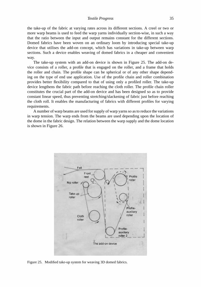
Textile Progress 35
the take-up of the fabric at varying rates across its different sections. A creel or two ormore warp beams is used to feed the warp yarns individually section-wise, in such a waythat the ratio between the input and output remains constant for the different sections.Domed fabrics have been woven on an ordinary loom by introducing special take-updevice that utilises the add-on concept, which has variations in take-up between warpsections. Such a device enables weaving of domed fabrics in a cheaper and convenientway.
The take-up system with an add-on device is shown in Figure 25. The add-on de-vice consists of a roller, a profile that is engaged on the roller, and a frame that holdsthe roller and chain. The profile shape can be spherical or of any other shape depend-ing on the type of end use application. Use of the profile chain and roller combinationprovides better flexibility compared to that of using only a profiled roller. The take-updevice lengthens the fabric path before reaching the cloth roller. The profile chain rollerconstitutes the crucial part of the add-on device and has been designed so as to provideconstant linear speed, thus preventing stretching/slackening of fabric just before reachingthe cloth roll. It enables the manufacturing of fabrics with different profiles for varyingrequirements.
A number of warp beams are used for supply of warp yarns so as to reduce the variationsin warp tension. The warp ends from the beams are used depending upon the location ofthe dome in the fabric design. The relation between the warp supply and the dome locationis shown in Figure 26.
Figure 25. Modified take-up system for weaving 3D domed fabrics.

36 N. Gokarneshan and R. Alagirusamy
Figure 26. Dome location and warp yarns.
8.3 Design aspects of 3D domed fabrics
A woven structure should necessarily comprise of various structural aspects, such as numberof layers, weave types and thread densities, so as to design fabrics for technical textiles.Three-dimensional domed shaped fabrics can be designed by the use of single-layer fabricswith plain, 2/2 twill, 4-end, and 6-end sateen. Double, treble and angle-interlock fabricswith two and three layers of weft yarns can also be used. The requirement of the warp andweft densities for various fabrics are shown in Table 5.
Table 5. Type of weaves and thread densities [87].
Type of weave *Warp sett/cm *Weft sett/cm
Plain 10,12,14 8,10,11,13,14,162/2 twill 16,17,18 10,11,13,14,16,18,194-end sateen 16,17,18 10,11,13,14,16,18,196-end sateen 16,17,18 10,11,13,14,16,18,19Double cloth 24 16,19,22,26,29,32Treble cloth 36 24,29,34,38,432-layer angle-interlock 24,27 13,1619,223-layer angle-interlock 24,27 19,24,29,34
*The warp and weft yarns in all the weaves are 66 tex.

Textile Progress 37
8.4 Testing and evaluation of dome effect
The dome effect has been evaluated by using two methods. The first method involvescalculation of dome index as follows:
Dome index= weft density of flat section− weft density at top of dome
weft density of flat section× 100.
As no surplus weft yarns have been included in the dome formation, the dome indexindicates the relative change in weft density, and is therefore useful to indicate the domeeffect. The dome index takes into consideration only the change in weft density but not thewarp, as they are firmly held by the reed and do not much affect the dome formation.
In the second method, the dome effect is measured by using the mouldability tester[89]. The dome effect is measured in terms of its depth/height under various conditions ofloading, and is therefore used to indicate the dome effect and also the fabric mouldability.
8.5 Dome index for single-layer fabrics
The density of weft yarn has been found to have significant effect on the dome formation,and the lower the weft density, the better is the formation of dome effect. It is to be notedthat the dome effect is due to the uneven take-up of the fabric and let-off by a multiplewarp beam. Such an arrangement enables only the weft yarns to be displaced and take on acurved outline to form the dome. This, however, is possible with only lower weft density,which enables movement of the filling yarns, resulting in dome formation. Such a freemovement is restricted in the case of higher weft densities. On the other hand, the type ofweave also influences the dome formation. In the case of plain weaves, the dome formationis the most difficult due to its minimum float length. Sateen weaves produce the best domeeffect due to longest average float length. The higher the value of the dome index, the betterthe dome effect, and hence sateen weaves give the highest value of dome effect. Domeeffect is more pronounced in looser woven structures due to greater mobility between warpand weft yarns.
8.6 Dome index for multi-layer fabrics
Double and treble cloths are included in this category. Plain weave is used in each layer,and also angle-interlock structures are used with two and three weft layers. In the case offabrics with identical warp density and different weft densities, the greater the number offabric layers, the smaller the dome index values. In other words, fabrics with more layerswill have poorer dome formation. In the case of fabrics with angle-interlock structures,the dome index value decreases with higher weft densities per weft layer. This is valid forfabrics with two and three weft layers. It also implies that a greater number of weft layersin the angle-interlock fabrics reduces the dome index values. This also holds good in thecase of multi-layer fabrics.
8.7 Dome depth for single-layer fabrics
A number of methods can be used to measure the depth of the dome by means of thedeformation tester. In one method, a metal probe with a mass of about 190 grams is used.The fabric to be tested is held between the groove of the top and bottom rings. The methodenables the dome effect to be tested, as well as the mouldability of the fabric. In anothermethod, contrastingly, a very light plastic tube probe with a mass of about 12 grams is used.

38 N. Gokarneshan and R. Alagirusamy
The fabric is supported by a board having a hole with identical diameter as the rings, and isheld between the top and bottom rings. This method measures the dome depth but not themouldability, owing to the small mass of the probe.
In the case of both the methods of testing dome depth, it is found to decrease withincrease in weft density. This is valid for fabrics of various weaves woven as a single layer.The dome depth measured by the first method is found to be higher than that measuredby the second method. In both cases, the dome depth generally increases with the increasein the average float length of the weave, which confirms the fact that fabrics with looserstructures are more dome formable in weaving.
8.8 Dome depth for multi-layer fabrics
In the case of multi-layer fabrics, the tests for dome depth reveal that a higher number offabric layers reduces the dome depth. In the case of fabrics with angle-interlock structures,the increase in weft density reduces the dome depth. This is found to be valid for boththe test methods. The case of multi-layer fabrics is dealt with more elaborately in Tayyar’sdoctoral thesis [90].
8.9 Comparison of dome index and depth
The two parameters, namely, dome index and dome depth, have been correlated and evalu-ated for single as well as multi-layer plain woven fabrics. The correlations have been foundto be highly significant at 95% confidence level. Both the test methods have been foundvalid for both the test methods for dome effect. The dome index method is useful in caseswhere the mouldability tester is not available. However, the dome depth method gives muchfaster results with the help of a mouldability tester.
9. Use of glass yarns in 3D preforms
Nowadays, 3D fabrics are being more widely used as reinforcing medium in compositeapplications [91]. Three-dimensional fabrics are manufactured by various methods [92–96] so as to overcome or reduce the problem of delamination of composite materials,particularly during bending [97,98]. The introduction of a through-the-thickness elementprovides considerable resistance to crack propagation and this would appear to be the mainsource of breakdown in composites [99]. The advantage of using 3D fabric in compositesis that it enables reduction of manufacturing costs by reducing the duration of manuallabour for laying up the layers of the reinforcement manually. Thus, a new generationof reinforcing fabrics have been developed in composite manufacture. A major problemarises in the waste disposal during trimming, particularly in the mass production such asthe automotive industries. An attempt has therefore been made to manufacture reinforcingmaterials that are almost net-shaped so as to reduce the waste as far as possible at thecomposite manufacturing stage.
In the manufacture of 3D fabrics, the internal stresses that are created within thereinforcement have to be considered. This produces a bowing or curving effect in the 3Dfabric after it is impregnated with resin and cured. In the conventional method, this problemis overcome by building the layers of impregnated fabric in a symmetrical way. This is,however, difficult to achieve in the manufacture of 3D woven preforms.

Textile Progress 39
Figure 27. Warp linkage between fabric layers.
But the problem has been overcome to an extent by uniformly constructing fabricsabout their mid-plane. An almost net-shaped 3D preform has been produced on a computer-controlled dobby loom using glass yarn [100].
Besides texturised glass yarns, flat continuous filament glass yarns have also beenused. The flat continuous filament glass yarn is found to be stronger than its texturisedcounterpart and is also more compact [101]. Thinner and stronger preforms that are moredensely compacted are also produced. Thus, for a given construction, the 3D reinforcementproduced with continuous filament glass yarns exhibit better inter-plane strength with alower proportion of fibre in the through-the-thickness together with higher volume fractions,than its texturised glass counterpart.
9.1 Manufacturing of textured glass yarn reinforcement
Texturised glass yarn has been used in the manufacturing of 3D reinforcement. The advan-tage of using the yarn is that it has greater bulk than uncrimped filament yarns, and alsoenables easier penetration of the resin into the tight reinforcement structures. The yarn hasbeen woven into a four-layered interlinked structure in such a way that it permitted openingup of the structure to form a T section, where the warp yarns lie along the direction ofthe length of stem. Earlier research [102] revealed that selvedges had a considerable influ-ence on the performance of structural reinforcements, and hence fabrics woven with glassyarns had selvedges as an important component of the fabric. Such a fabric reinforcementwith different layers connected together integrally are considered here as 3D fabrics orcomponents.
A number of preforms have been woven with a T section, wherein the stem covered fourfabric layers and the flanges covered two layers. Each layer of the fabric reinforcement hasbeen woven as a plain structure and the individual warp ends connected together the fabriclayers. Since the woven structure in each fabric layer is plain, two heald shafts have beenused for each layer, and thus eight healds have been used. The individual fabric layers havebeen connected together by shifting warp yarns of the first layer to the third layer and thatof the second layer to the fourth and vice versa, for one pick before returning them to theiroriginal position. A type of such linkage between fabric layers is shown in Figure 27. Thislinkage formation over a pick has been found to give the best performance characteristicsof the corresponding structural components. Such a construction is designed to eliminate orreduce spring back in the finished 3D component. Every warp yarn in the structure is utilisedto provide the through-the-thickness element of reinforcement. A variety of preforms couldbe produced using this method.

40 N. Gokarneshan and R. Alagirusamy
Table 6. Technical specifications of reinforcements [100].
Threads/cm/layerFabric thickness Weight g/m3 × 100
Reinforcement Ends Picks (mm) g/m2 density of glass
Type 1 3 2 4.5 3405 29.8Type 2 3 2 4.6 3425 29.3Type 3 3 2 4.7 3398 28.4Type 4 3 2 4.8 3410 28.0Type 5 3 2 4.2 3403 31.9Type 6 3 2 4.3 3400 31.1
A typical T section of the preform produced by folding up of the woven structure isshown in the Figure 28. The preforms have been woven with varying proportions of yarnin theZ direction. This has been achieved by forming links between layers. The technicalspecifications of the reinforcements are given in Table 6.
The structures shown in the table are almost of equal mass. The ratio of the weight ofthe structure in grams/cubic metre to the weight of a cubic metre of glass gives an indicationof the volume of the fibre in the fabric and enables us to assess the possibility of producingcomposites of a given thickness with a specific fibre volume fraction.
Figure 28. A T section.
9.2 Manufacturing of flat continuous filament glass yarn reinforcement
The strength of the flat continuous filament yarn has been found to be roughly double thatof the texturised yarn. However, with regard to tenacity, the yarn is approximately halfthe value quoted in the literature [103]. Such a trend has also been observed in other testsexamining tensile strength of strong, brittle continuous filament yarns [104]. It has been

Textile Progress 41
Table 7. Technical specifications of reinforcements [101].
Threads/cm/layerg/m3× 100
Reinforcement Ends Picks Fabric thickness (mm) Weight g/m2 density of glass
Type 1 3 2 2.5 2501 29.8Type 2 3 2 2.4 2616 29.3Type 3 3 2 2.6 2668 28.4Type 4 3 2 2.6 2566 28.0Type 5 3 2 2.6 2686 31.9Type 6 3 2 2.75 2553 31.1
noted that in many instances the strength of these types of yarn are measured with the fibreembedded in a resin [105].
The yarn has been woven into six types of preform structure, as in the previous case.Out of these, three were woven similar to those of the corresponding texturised yarnsand the remaining three have been woven with constructions that are selected to give abalanced spread of through-the-thickness elements [101]. The technical details of the 3Dreinforcements are given in Table 7.
9.3 Evaluation and results
An attempt has been made to establish the relation between the properties of yarn, fabricand composite. A test method has been developed for the purpose and can be used fortesting of fabric, preform and composite samples. The method provides useful informationon the properties of the composites. It is also a measure of the effectiveness of the through-the-thickness element as a barrier to delamination. This is also known as the inter-planestrength and is the force required to separate the connected layers between the fabric layersof the reinforcement.
Tests conducted on the inter-plane strength using a computer-controlled instron tensileinstrument (grab method) have shown that as the proportion of the through-the-thicknessyarn is increased, the inter-plane strength is increased. The inter-plane strength increaseswith an increase in the proportion of yarn in theZ direction, and as many parallel yarns aspossible should be woven into the juncture of the flanges and web.
The weight of the fabrics is found to be 25% lighter than that of the ones produced withtextured yarns. The greatest difference is found to be in the thickness, as can be seen fromthe two tables (textured and flat yarns). The bulk of the texturised yarn makes the averagethickness of the structures 4.5 mm, while the average thickness of the continuous filamentstructures is 2.6 mm. The differences reflect in the densities of the two reinforcements.The density of the textured type is 75% that of the flat filament type. When comparing thevolume of fibre in a given volume of fabric, the continuous filament reinforcement is about20% higher.
Just as in the case of texturised reinforcements, the relation between the proportionof yarn in theZ direction and the inter-plane strength, which has been measured by thegrab method, has been found to be a linear one. The inter-plane strengths of the texturisedT sections are similar to that of the continuous filament sections, despite the fact that thestrength of texturised yarn is about half that of continuous filament yarns. While the lineartensile strength of texturised yarn is nearly half that of continuous yarn, the loop strengths

42 N. Gokarneshan and R. Alagirusamy
of both yarns are almost equal. The inter-plane strength in the case of texturised T sectionsis higher than those for continuous filament sections even though the tensile strengths differ.Studies show that the influence of the through-the-thickness parameter on the inter-planestrength is complex. They are affected by factors such as type of construction, and also bythe type of yarn used to construct the component.
10. Weaving of medical textiles
Three-dimensional fabrics have recently entered the medical field. Their specific area ofapplication is in the weaving of vascular prosthesis. Vascular prosthesis are surgicallyimplantable materials. They are used to replace the defective blood vessels in patientsso as to improve blood circulation. Conventional types of prosthesis were made from aircorps parachute cloth, vignon sailcloth and other types of clothing materials. Materialssuch as nylon, Teflon, orlon, stainless steel, glass and Dacron polyester fibre have beenfound to be highly suitable for the manufacture of prosthesis. These materials were foundto be significantly stable with regard to resistance to degradation, strength and were notadversely affected by other factors [106]. Dacron polyester, which has bio-compatibilityand high tensile strength, is being used over a period of time as suture thread or artificialligaments [107–109].
10.1 Comparison of woven and knitted grafts
Vascular grafts are manufactured on a very small scale as woven and knitted grafts, andalso as velour and Gore Tex. Knitted grafts may be of warp or weft knitted types [110].Velour is a fabric made from texturised yarns, wherein the filaments are exposed on eitheror both sides of the velour grafts. The woven grafts have been used earlier. Gore Tex graftsare made of polytetrafluoroethylene and moulded as one single piece. Woven grafts havea good bursting strength and resistance to fatigue. They can be woven compact enough tomake them least permeable to water and blood. They are manufactured as seamless tubeson special tape looms with shuttles.
Knitted grafts are comparatively more porous than woven grafts. In the case of graftswith weft-knitted structures, the mobility of yarn is higher in the course direction than inthe wale direction. This is a drawback since it leads to increase in diameter with time. Sucha problem ultimately leads to rupture of the graft. Hence, weft-knitted structures are notpreferred in the manufacture of grafts. Conversely, warp-knitted fabrics are highly versatilesince they can imitate woven- or weft-knitted with regard to mechanical performance.Also, they are dimensionally stable comparatively and show higher compliance in thecourse direction than in the wale direction.
Woven grafts are manufactured on tape looms with shuttle, specially designed forvascular prosthesis. The grafts are made as tubes without seams. Single jersey grafts aremanufactured on flat knitting machines with very fine gauge and specifically designed forproducing grafts. Tubular warp-knitted structures are produced on warp knitting machinesequipped with two needle bars.
10.2 Manufacturing technology
A prototype of a manually operated loom has been developed, which is suitable for weavingstraight as well as bifurcated vascular prosthesis [110]. It is based upon the principle of3D weaving. A separate warp yarn selection device is incorporated. The main trunk of the
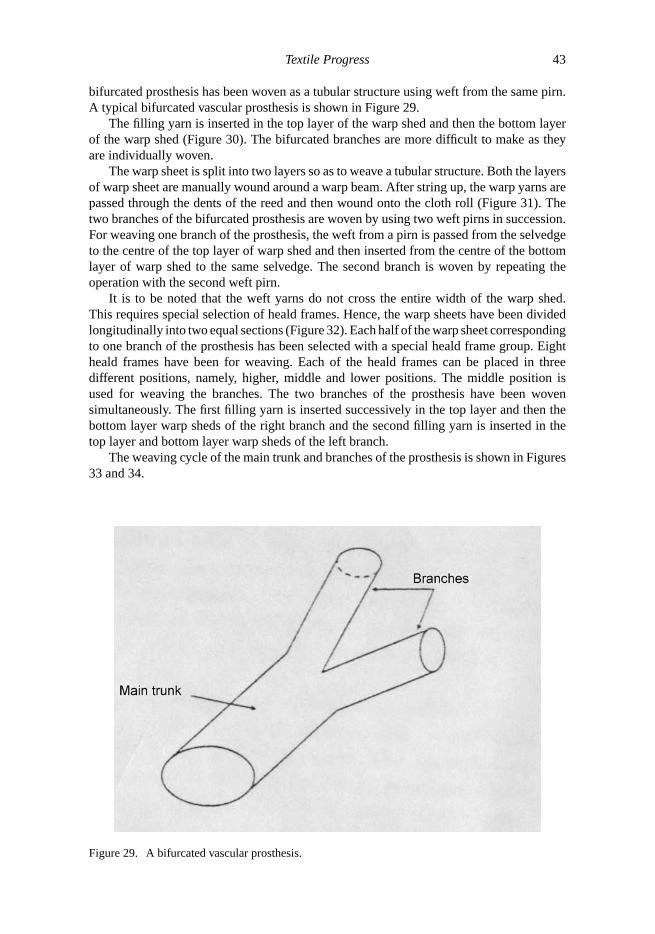
Textile Progress 43
bifurcated prosthesis has been woven as a tubular structure using weft from the same pirn.A typical bifurcated vascular prosthesis is shown in Figure 29.
The filling yarn is inserted in the top layer of the warp shed and then the bottom layerof the warp shed (Figure 30). The bifurcated branches are more difficult to make as theyare individually woven.
The warp sheet is split into two layers so as to weave a tubular structure. Both the layersof warp sheet are manually wound around a warp beam. After string up, the warp yarns arepassed through the dents of the reed and then wound onto the cloth roll (Figure 31). Thetwo branches of the bifurcated prosthesis are woven by using two weft pirns in succession.For weaving one branch of the prosthesis, the weft from a pirn is passed from the selvedgeto the centre of the top layer of warp shed and then inserted from the centre of the bottomlayer of warp shed to the same selvedge. The second branch is woven by repeating theoperation with the second weft pirn.
It is to be noted that the weft yarns do not cross the entire width of the warp shed.This requires special selection of heald frames. Hence, the warp sheets have been dividedlongitudinally into two equal sections (Figure 32). Each half of the warp sheet correspondingto one branch of the prosthesis has been selected with a special heald frame group. Eightheald frames have been for weaving. Each of the heald frames can be placed in threedifferent positions, namely, higher, middle and lower positions. The middle position isused for weaving the branches. The two branches of the prosthesis have been wovensimultaneously. The first filling yarn is inserted successively in the top layer and then thebottom layer warp sheds of the right branch and the second filling yarn is inserted in thetop layer and bottom layer warp sheds of the left branch.
The weaving cycle of the main trunk and branches of the prosthesis is shown in Figures33 and 34.
Figure 29. A bifurcated vascular prosthesis.

44 N. Gokarneshan and R. Alagirusamy
Figure 30. Tubular woven structure.
During the first selection, the odd numbered warp threads are lifted, and during thesecond selection, the even numbered warp threads are lifted.
The woven bifurcated prosthesis thus has the following technical particulars:
Type of material – Texturised Dacron polyester yarns (circular cross-section).Linear density – warp and weft – 16 tex (34 fibres per yarn cross-section).Number of yarns per warp sheet – 160 (for right branch).160 (for left branch).Reed particulars – 20 dents/cm.4 ends/dent – 2 yarns for top warp sheet.2 yarns for bottom warp sheet.
Dacron polyester yarn has been found suitable as it has sufficient resistance to be wovenwithout ruptures. Mechanical treatments comprising of compaction and crimping and also
Figure 31. Warp shed arrangement.
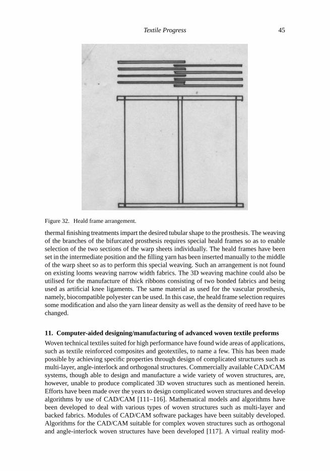
Textile Progress 45
Figure 32. Heald frame arrangement.
thermal finishing treatments impart the desired tubular shape to the prosthesis. The weavingof the branches of the bifurcated prosthesis requires special heald frames so as to enableselection of the two sections of the warp sheets individually. The heald frames have beenset in the intermediate position and the filling yarn has been inserted manually to the middleof the warp sheet so as to perform this special weaving. Such an arrangement is not foundon existing looms weaving narrow width fabrics. The 3D weaving machine could also beutilised for the manufacture of thick ribbons consisting of two bonded fabrics and beingused as artificial knee ligaments. The same material as used for the vascular prosthesis,namely, biocompatible polyester can be used. In this case, the heald frame selection requiressome modification and also the yarn linear density as well as the density of reed have to bechanged.
11. Computer-aided designing/manufacturing of advanced woven textile preforms
Woven technical textiles suited for high performance have found wide areas of applications,such as textile reinforced composites and geotextiles, to name a few. This has been madepossible by achieving specific properties through design of complicated structures such asmulti-layer, angle-interlock and orthogonal structures. Commercially available CAD/CAMsystems, though able to design and manufacture a wide variety of woven structures, are,however, unable to produce complicated 3D woven structures such as mentioned herein.Efforts have been made over the years to design complicated woven structures and developalgorithms by use of CAD/CAM [111–116]. Mathematical models and algorithms havebeen developed to deal with various types of woven structures such as multi-layer andbacked fabrics. Modules of CAD/CAM software packages have been suitably developed.Algorithms for the CAD/CAM suitable for complex woven structures such as orthogonaland angle-interlock woven structures have been developed [117]. A virtual reality mod-

46 N. Gokarneshan and R. Alagirusamy
First heald frame selection – Opening of top and bottom layers of sheds
Insertion of weft on the top layer of warp shed
Beat up of reed
Second heald frame selection – Opening of top and bottom layers of warp shed
Insertion of filling yarn in lower shed
Beat up of reed
Movement of warp sheet
Figure 33. Flow chart indicating weaving of prosthesis main trunk.
elling language has been used. Such models enable visualisation of the complicated wovenstructures and evaluation of their physical and other properties.
11.1 Orthogonal structures
An orthogonal structure comprises of three sets of yarn, namely, the straight warp yarn,straight weft yarn and the binding warp yarn. The first two types of yarns constitute thenon-interlaced body structure, which is followed by the binding weave through the bindingwarp yarns. The number of layers of either the straight warp or weft yarns determines thethickness of the structure. Based on the nature of the binding weave, two types of orthogonalstructures can be woven, namely the ordinary and the improved types [118]. In the firsttype, only a single-binding warp set is used, and in the second type, two binding warp sets

Textile Progress 47
Left branch: Intermediate position
Left branch: First selection
Left weft insertion: top shed
Reed operation
Left branch: intermediate position
Right branch: First selection
Right weft insertion: Top shed
Reed operation
Right weft insertion: Bottom shed
Reed operation
Right branch: intermediate position
Right branch: Second selection
Right weft insertion: top shed
Reed operation
Left branch: Second selection
Left weft insertion: top shed
Reed operation
Left weft insertion: bottom shed
Reed operation
Right weft insertion: Bottom shed
Reed operation
Right branch: intermediate position
Movement of warp sheet
Figure 34. Flow chart indicating weaving cycle of prosthesis branches.

48 N. Gokarneshan and R. Alagirusamy
with inverted binding weaves are used. The number of layers of straight warp yarns,N1,and the number of layers of straight weft,N2, can be related as shown below:
N2 = N1 + 1.
The weaves used in orthogonal structures are shown in Figure 35.The warp and weft repeats of an orthogonal structure can be calculated based upon
the numbers of layers of straight warp and weft and the warp repeat and weft repeat of thebinding weave. A binary matrix has been used for the mathematical representation of theweave. Every component of the matrix is assigned to either 0 or 1, corresponding to a blankor a mark on the design paper. The method of creation of weave pattern used in the case ofsingle-layer fabrics can be used for generation of the binding weave [119].
The orthogonal weave can be generated by knowing the number of straight warp or weftlayers, the binding weave, and the type of orthogonal structure, i.e. ordinary or improved.Thus, by knowing these parameters, the matrix for the non-interlaced body structure can begenerated. The non-interlaced body structure is held together by introduction of the bindingweave. The weft repeats of the binding weave and the inverse binding weave should beextended so as to suit the straight weft repeat before the introduction by use of specialequation. A number of parameters are used to create the matrix for the non-interlaced bodystructure.
11.2 Angle-interlock structures
In the case of these structures, the warp threads get interlaced with many weft threads alongthe direction of fabric thickness. The geometry of the structures can be varied by changingthe number of weft yarn layers, and also by changing the manner in which the weft yarnsare interlaced by the warp threads [120]. The number of weft yarn layers is greater than orequal to the number of weft layers interlaced by the warp yarns.
The different types of angle-interlock structures are shown in Figure 36. An integratedstructure is formed through interlacement of the interlocking warp yarns with weft yarns ina diagonal manner, which reduces the undue bending of the warp threads. All the warp yarnsneed not necessarily interlace with weft yarns in the same manner. The number of weftlayers and the interlocking depth should be odd numbers and should be greater than three[121]. They can also be even numbers, resulting in perfectly acceptable angle-interlockstructures [122]. In this case, the number of weft layers should be equal to the number ofweft layers locked by warp ends. The warp yarns in the angle-interlocking structure areof two types, viz., the interlocking and the non-interlocking warp yarns. The numbers ofoverall, interlocking, and non-interlocking warp yarns are calculated as shown below:
N1 = N2 + 1
N3 = N2 − N4 + 1,
whereN1 = number of overall warp ends,N2 = number of weft layers,N3 = number of non-interwarp locking ends,N4 = number of interlocking warp ends.The matrix for the angle-interlock structures can be generated from the structural factors,
namely, the number of weft layers and the number of weft layers locked by the warp ends,and the calculated parameters mentioned above.
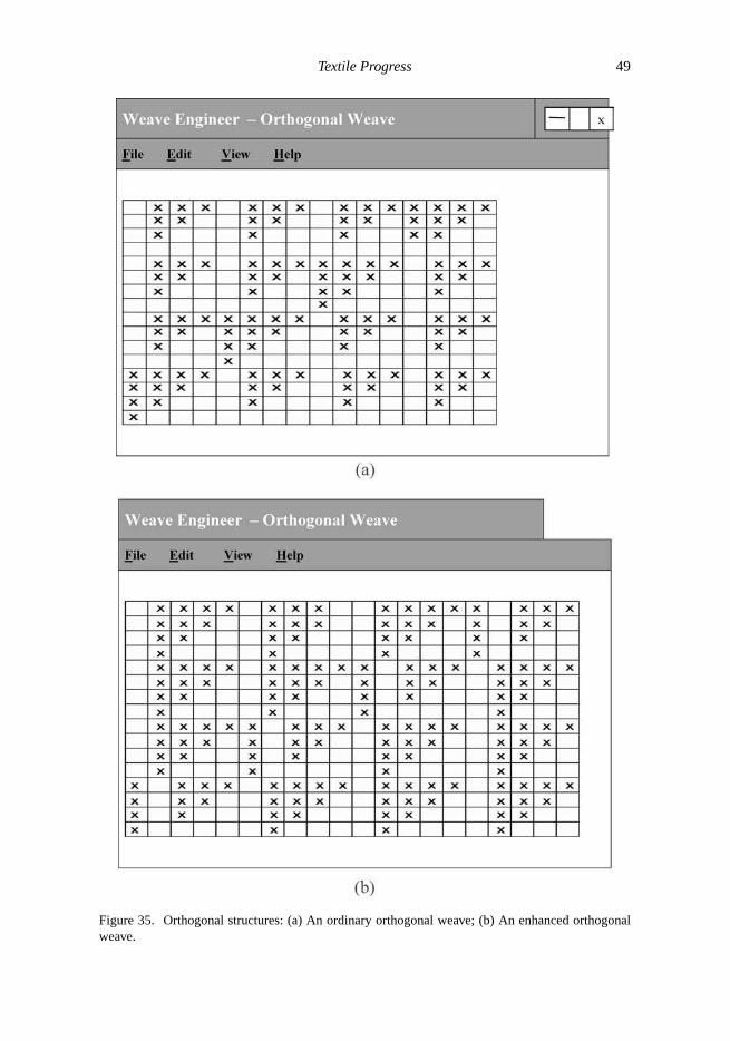
Textile Progress 49
Figure 35. Orthogonal structures: (a) An ordinary orthogonal weave; (b) An enhanced orthogonalweave.

50 N. Gokarneshan and R. Alagirusamy
Figure 36. Types of angle-interlock structures.
11.3 Automatic generation of lifting plans and requirements of weaver’s beams
The computer-aided manufacturing technology has been effectively implemented in theweaving of advanced woven structures. The shedding mechanism is controlled by thegeneration of instruction codes, which are termed as the lifting plan. By knowing the typeof weave and the draft plan, the lifting plan for weaving the fabric can be automaticallygenerated.
In the case of weaving advanced 3D woven fabrics, the warp yarns are consumed atdifferent rates based on the nature of the weave. A number of weaver’s beams is used tosupply the warp. The correlation of individual warp yarns to a weaver’s beam in the caseof advanced 3D woven structure is a very tedious job and could be erroneous too. Use ofCAD/CAM software enables us to calculate the minimum number of weaver’s beams andalso easily correlate individual warp yarns to a weaver’s beam.
Three series of warp yarns, namely, the straight warp yarns, binding warp yarns, andinverse binding warp yarns make up the orthogonal structure. The straight warp yarns areunder a different tension compared with the other two series of warp yarns. The bindingwarp yarns and inverse binding warp yarns have the same yarn consumption rate from beam,though moving in opposite directions in the fabric. Hence, two weaver’s beams would beadequate for weaving an orthogonal structure. The angle-interlock structure can have amaximum of two series of warp yarns, namely, binding warp yarns and unbinding warpyarns. In this case, the structure merely requires a single or a maximum of two weaver’sbeams based on the use of non-interlacing yarns.
11.4 Programming implementation
The models and algorithms used here have been implemented with the use of two MicrosoftWindows based programs for both angle-interlock and orthogonal woven structures. Theprograms easily enable the user to give the necessary input structural parameters. The

Textile Progress 51
Figure 37. Windows program showing draft and lifting plans.
programs then automatically generate the weaves. The draft and lifting plans have beencreated for both types of the woven structures so as to enable the computer-aided weavingof the same. The draft and lifting plan of the improved type of orthogonal woven structureis shown in Figure 37. The programs also enable us to view the cross-sections of thestructures (Figure 38). Moreover, both the structures can be visualised so as to provide 3Dviews of the structures that would be useful in a number of ways such as assessment oftheir physical and mechanical properties. The standard Windows convention is used for theprogram interface and are hence user-friendly. Provision is available to save and load theweaves whenever necessary. Also, the data can be shared between applications in MicrosoftWindows.
11.5 Three-dimensional visualisation
As discussed previously, both the types of 3D woven structures can be visualised in three-dimensions. The VRML has proved to be a useful tool in this case [122], which alsouses the general concept of computer graphics. A VRML file contains the description of3D objects and 3D environments termed as the “world”. A three-dimensional coordinatesystem is used for indicating the space in the world, in which all the three axes,X, Y andZ, pass through the source point. In the case of VRML, theX-axis is directed rightwards,the Y -axis upwards, and theZ-axis towards the operator. The three changes that occurin a 3D world are translation, rotation and scaling. The translation involves moving anobject from one point to another, while the rotation turns around objects in the three axes,

52 N. Gokarneshan and R. Alagirusamy
Figure 38. Cross-sectional views: (a) Orthogonal interlock structure; (b) Angle-interlock structure.
Figure 39. Lenticular cross-section.
Textile Progress 53
and scaling alters the size of the objects. The 3D image of a yarn can be created byspecifying the yarn cross-section and yarn path within the 3D woven structures. The imagethat is generated for each component yarn is then transformed to the specific point. Thecomponent yarns are combined together so as to create the 3D image of the complex wovenstructure. The cross-section of the yarn is assumed to be lenticular in shape, as shown inthe Figure 38. It is formed by joining two similar arcs facing each other. The radius ofthe lenticular cross-section can be calculated by considering its width and height as givenbelow (Figure 39):
Radius= (width2 + height2)/(4 × height).
A parametric representation of an origin-centred circle is used so as to generate the arc[123].
12. Application areas of 3D woven fabrics
As already pointed out, 3D woven fabrics have wide areas of application. The areas ofapplication depend upon the method of manufacture adopted. Various methods of weavingare used to manufacture 3D preforms with different structures. Angular interlock andperpendicular multi-layer fabrics could be woven by using the multi-warp weaving methods.Other types of woven preforms, such as those with cylindrical profiles, can be woven onlooms specially designed for the purpose. The non-interlaced 3D fabric forming process isconsiderably simple and could be utilised to produce fabrics with solid and tubular profiles.In the case of simple solid fabric constructions, the three series of yarns are placed asperpendicular planes, and in the case of tubular fabric constructions like cones and cylinders,the three series of yarns will be placed axially, radially and circumferentially. The actual3D weaving technology that has been developed is useful to machinery manufacturers andmanufacturers of technical textiles for meeting the requirements of a variety of end useapplications. The method is to be developed further.
The 3D weaving method has the following areas of applications:
� Filter fabrics, meshes used in cutting tools, etc.� Fabrics for ballistic protection.� Aquatic applications.� Medical uses such as ligaments and scaffolds.� High performance sports materials, such as shoe shells.� Advanced textile composites of flexible and rigid types.
One interesting aspect of the 3D weaving process is that it produces fabrics on avolumetric basis, whereas the 2D weaving process produces fabrics on an areal basis.Machine speed is not an important criterion, since quality of the material is of primeconcern. It is required to produce high value in relatively low quantities. Domed fabrics,also known as fabrics with double curvatures, are found to be suitable in certain typesof apparel and technical applications. The double curvatures can be obtained by the useof moulds, during the production of textile composites. In the process, additional strainwill be imparted to the textile reinforcement and this is unavoidable. The important areasof application include military and police helmets, bra cups used in fashion and clothing,female body armour, car door lining material, etc. In the case of helmets, seamless fabricsare used with double curvature so as to improve protection and enhance the efficiency inmanufacturing. Three-dimensional fabrics have recently entered the medical field. Their

54 N. Gokarneshan and R. Alagirusamy
specific area of application is in the weaving of vascular prosthesis. Vascular prosthesisare surgically implantable materials. They are used to replace the defective blood vesselsin patients so as to improve blood circulation. Conventional types of prosthesis were madefrom air corps parachute cloth, vignon sailcloth, and other types of clothing materials.Materials such as nylon, Teflon, orlon, stainless steel, glass, and Dacron polyester fibrehave been found to be highly suitable for the manufacture of prosthesis. These materialswere found to be significantly stable with regard to resistance to degradation, strength, andwere not adversely affected by other factors. Dacron polyester, which has bio-compatibilityand high tensile strength, is being used over a period of time as suture thread or artificialligaments.
13. Summary
Three-dimensional fabrics are generally manufactured for composite applications. Theycould be produced by different methods such as weaving, knitting and braiding. Funda-mental aspects underlying the weaving of 3D fabrics are discussed and their differences,as compared with their 2D counter part, are highlighted. The shedding system for weav-ing 3D fabrics differs from that of 2D weaving. Conversion of 2D into 3D fabrics hasbeen possible by means of computer-aided weaving on conventional looms in systematicstages. A true 3D woven fabric is one in which the component yarns are placed in threemutually perpendicular planes in relation to one another. Other types of 3D fabrics coulddeviate from this principle such as those produced by the noobing technique. In the caseof preforms used in advanced composite materials, the integrity of the structure is con-sidered to be the main criteria, as the reinforcements made out of these become a crucialfactor in deciding the mechanical characteristics of the composites. Hence, textile rein-forcements have found varied applications in composites owing to their adaptability, whichenables them to meet a wide range of reinforcing requirements. Three-dimensional fabricswoven for advanced composite preforms can be of I-shapes and double-cross shapes inplane form. Multi-axial multi-layer 3D preforms has been produced by special weavingtechniques such as tri-axial weaving, lappet weaving and pile weaving. Domed fabrics,also known as fabrics with double curvatures, are found to be suitable in certain types ofapparel and technical applications. An almost net-shaped 3D preform has been producedon a computer-controlled dobby loom using glass yarn, complicated structures such asmulti-layer, angle-interlock and orthogonal structures. Commercially available CAD/CAMsystems, though able to design and manufacture a wide variety of woven structures, are,however, unable to produce complicated 3D woven structures such as multi-layer, angle-interlock, and orthogonal structures. Mathematical models and algorithms have been de-veloped to deal with such types of woven structures. Modules of CAD/CAM softwarepackages have been suitably developed. Algorithms for the CAD/CAM suitable for com-plex woven structures, such as orthogonal and angle-interlock woven structures, have beendeveloped.
References[1] N. Khokar, J. Textil. Inst. 87 Part I (1996), p.97.[2] D.P. Calamito et al.,Woven Multi-layer angle interlock fabrics and methods of making same,
HITCO USA EP 0 422 293, (GB: 11 Oct 1989).[3] Thick woven fabrics, HITCO, USA, BP 1 296 369 (USA: 6 Jan. 1989).[4] D.P. Calamito and R.H. Pusch,Integrally woven multi-apertured multi-layer angle interlock
fabrics, HITCO, USA, USP 5 080 142 (6 April 1989).
Textile Progress 55
[5] K. Takenaka and E. Sato,Woven fabric having multi-layer structure and composite materialcomprising the woven fabric, AKKK Kaisha, USP 5 021 283 (Japan: 31 March 1987).
[6] K. Greenwood,‘Loom’, the secretary of state for defence, England USP 3 818 951 (Div. Ser.No. 92 982, Nov 1970).
[7] K. Fukuta et al.,Three-dimensionally latticed flexible structure composite. Agency of industrialscience and technology and ministry of international trade and industry, Japan USP 4 336 296(Japan: 27 Dec, 1978).
[8] S. Raz,Warp Knitting Production, Verlag Melliand Textilberichte GmBH, Heidelberg, Ger-many, 1987, p.451.
[9] D.S. Brookstein,Multi-layer interlock braiding – A new method for producing textile reinforc-ing preforms, 3rd International Tech-Textile Symposium 1991.
[10] P. D. Emerson,Modern developments in 3 dimensional fabrics, in Modern Textiles, 1969, p.50.[11] Improvements in and relating to weaving, Monsanto Company, USA, BP 1 292 970 (USA: 31
Dec.1968).[12] K. Fukuta et al.,Three-dimensional fabric, and method and loom construction for 3 834 424,
(Japan: 19 May 1972).[13] R.W. King, Apparatus for fabricating three-dimensional fabric material, Avco Corporation,
USA, USP 3955 602 (Division of Ser. No. 5=675 367, 16 Oct. 1967, which is a continuationof Ser. No. 220 510: 24 Jan., 1972).
[14] J. Banos et al.,Method and machine for three-dimensional weaving for obtaining woventhree-dimensional reinforcements of revolution, Societe Nationale Industriale Aero-Spatiale,France, USP 4 183 232 (France 20 June 1977).
[15] F.E. Schultz,Orthogonally woven reinforcing structure, General Electric Company, USA, USP3 993 812 (USA, 4 Jan, 1974).
[16] H.A. Holman, et al.,Loom for producing three dimensional weaves, McDonnell DouglasCorporation, USA, USP 4 019 540 (12 March 1976).
[17] Y. Sakatani, et al.,Profiled cross-section three-dimensional woven fabric, MJKK Kaisha andSCK Kaisha, Japan, EP 0331 310 (Japan, 29 Feb. 1988).
[18] Y. Yasui et al.,Three dimensional fabric and method of making the same, KKTJ Seisakusho,Japan, EP 0 426 878 (Japan. 26 May 1989).
[19] M.H. Mohmmed and Z.H. Zhang,Method of forming variable cross-sectional shaped threedimensional fabrics, North Carolina State University, USA WO 92/04489 (USA: 29 Aug.1990).
[20] M. Anahara et al.,Three dimensional textile and method of producing the same, KKTJSeisakusho, Japan. EP 0426 878 (Japan.26 May 1989).
[21] World Intellectual Property Organization,International Patent Classification,4th Ed., Hey-manns Verlag KG, Germany.
[22] F.K. Ko. Three-dimensional fabrics for composites, T.W. Chou and F.K. Ko, eds., ElsevierScience, Amsterdam, The Netherlands, 1989, p.1.
[23] F. Scardino,An introduction to textiles and their behaviour, T.W. Chou and F.K. Ko, eds.,Elsevier Science, Amsterdam, The Netherlands, 1989, p.129.
[24] M.H. Mohammed, Am. Sci. 78 (1990), p.530.[25] R. Robbins,Structural Components Produced by Modified Weaving Techniques, Text. Inst.
Industry, March (1970), p.71.[26] J.W.S. Hearle and G.W. Du. J. Textil. Inst. 81 (1990), p.360.[27] N. Khokar and E. Peterson,Khokar’s doctoral dissertation, 3D-weaving and noobing: Char-
acterization of interlaced and non-interlaced 3D fabric forming principles: Paper 2, A studyof the uniaxial noobing process, Department of polymeric materials, Chalmer’s university oftechnology, Gothenburg, Sweden, ISBN 91 7197- 492X, 1997.
[28] N. Khokar and E. Peterson,3D-weaving and noobing: Characterization of interlaced andnon-interlaced 3D fabric forming principles: Paper 3, An experimental unixaial noobingdevice: Working Design, construction and related aspects,Phd. Diss., Department of polymericmaterials, Chalmer’s University of Technology, Gothenburg, Sweden, ISBN 91 7197- 492X,1997.
[29] N. Khokar, and E. Peterson,3D-weaving and noobing: Characterization of interlaced andnon-interlaced 3D fabric forming principles: Paper 4, Introductory aspects of the 3D weavingprocess, Phd. Diss., Department of polymeric materials, Chalmer’s University of Technology,Gothenburg, Sweden, ISBN 91 7197- 492X, 1997.

56 N. Gokarneshan and R. Alagirusamy
[30] N. Khokar and E. Peterson,3D fabrics through the ‘True’ 3D-weaving process, Paper presentedat the world textile congress 1998, Huddersfield, UK, 1998.
[31] N. Khokar, J. Textil. Inst. 90 Part I (1999), p.570.[32] N. Khokar,Woven 3D fabric material and the method of producing the same, Biteam AB,
Sweden, Intl. Patent Application No. PCT/SE97/00356, 1997.[33] N. Khokar,Network-like 3D woven fabric material and the method of producing the same,
Biteam AB, Sweden, Intl. Patent Application No. PCT/SE97/00355, 1997.[34] H. Mzyk, and M. Tille, Deutsche Textiltechnik 18(4) (1968), p.225.[35] W.B. Pink,Improvements in weaving looms. BP 1 459 917, 1976.[36] N. Khokar,Woven material comprising tape-like warp and weft and the method of producing
the same, Biteam AB, Sweden, Swedish Patent Application No. 9701374-2, 1997.[37] R. Sulzer, Bulletin (periodical), Sulzer Ruti Ltd, Switzerland, Issue 33, April, 1998.[38] H. Mzyk and Tille, Deutsche Textiltechnik 18(4) (1968), p.225.[39] Ruti machinery works,Improvements in or relating to looms, Ruti Machinery Works Ltd.,
Switzerland, BP 365 000, 1974.[40] N. Khokar, J. Textil. Inst. 92(2) Part 1 (2001), p.193.[41] G.A. Fleury, R.L. Lavalle, and T.S. Ohnstad,Apparatus for weaving spheroidally contoured
fabric, Ciba-Geigy AG, Switzerland, EP 00302 012 B1, 1991.[42] A. Busgen, Tech. Textil. Int. (1995) p.18.[43] A. Busgen,Woven fabric having a bulging zone and method and apparatus of forming same,
USP. 3 446 251, 1999.[44] N.F. Dow,Triaxial Fabric, N.F. Doweave, USA, USP 3 446 251, 1969.[45] K. Oghara, R. Tsuboi, and M. Oghara,Tetra-axial woven fabrics and tetra-axial weaving
machine, Meidai Chemical Co. Ltd., Japan, EP 0263392 B1, 1994.[46] A. Weinberg,Method of shed opening of planar warp for high density three-dimensional
weaving, Jhonkar College of Textile Technology & Fashion, Israel, USP 5 449 025, 1995.[47] K. Fukuta, R. Onooka, A. Aoiki, and S. Isvmuraya,Three dimensionally latticed flexible
structure composites, US Patent 4,336,396.[48] R.W. King,Three dimensional fabric-material, US Patent 4,038,440 (July 26 1977).[49] H. Mohammed Mansour, Am. Sci., (1990), p.530.[50] W.E. Kruse and D. Rossello,Three dimensional reinforced structure, US Patent 3,834,424,
(Sept. 10 1974).[51] K. Greenwood, L. Zhao, and I. Porat, J. Textil. Inst. 1 Part 1, (1996), p.183.[52] K. Greenwood, L. Zhao, and I. Poat, J. Textil. Inst. 1 Part 1, (1996), p.195.[53] L. Zhao, I. Porat, and K. Greenwood, J. Textil. Inst. 2 Part 1, (1998), p.355.[54] F. Scardino,An introduction to textile structures and their behaviour, in Textile Structural
Composites, T.W. Chou and F.K. Ko, eds., Elsevier, Amsterdam, The Netherlands, 1988, p.1.[55] F.K. Ko, Three-dimensional fabrics for composites, in Textile Structural Composites, T.W.
Chou and F.K. Ko, eds., Elsevier, Amsterdam, The Netherlands, 1988, p.129.[56] A.P. Mouritz, M.K. Bannister, P.J. Falzon, and K.H. Leong, Composite 30 Part A (1999),
p.1445.[57] C.H. Chiu, and C.C. Cheng,Weaving mechanisms for spiral woven fabrics, SAMPE. J. (5/6)
(2001) p.44.[58] S. Chou, and H.E. Chen, Compos. Struct. 33 (1995), p.159.[59] R.A. Florentine,Apparatus for weaving three- dimensional,US Patent 4,312,261, 1982.[60] P. Popper and R.F. McConnell,Complex shaped braided structures, US patent 4,719,837,
1988.[61] R.M. Dow, New concept for multiple directional fabric formation, presented to 21st Interna-
tional SAMPE Technical Conference, Sept. 25–28, 1989.[62] C. Chang-Hsuan, and C. Chao-Chuan, Textil. Res. J. 73(1) (2003), p.37.[63] R. Marks, and A.T.C. Robinson,Principles of Weaving. Textile Institute, Manchester, UK,
1976.[64] O. Vinayak and R. Alagirusamy, Indian J. Fiber Textil. Res. 29 (2004) p.366.[65] W.S. Sondhelm, inHand Book of Technical Textiles, S.C. Anand ed., Woodhead Cambridge,
2000, p.62.[66] S.K. Punj, A. Mukhopadhyay, and A. Pattnayak, Textil. Asia, 33(6) (2002), p.33.[67] A.P. Mouritz, M.K. Bannister, P.J. Falzon, and K.H. Leong, Composite 30(12) Part. A (1999),
p.1445.
Textile Progress 57
[68] A.P. Mouritz, C. Boini, and I. Herszberg, Composite 30(7) Part. A (1999), p.859.[69] R. Kmaiya, B.A. Cheeseman, P. Popper, and T.W. Chou, Compos. Sci. Tech. 60(1) (2000),
p.33.[70] F.K. Ko and J. Kutz,Multiaxial warp knit for advanced composites, Proceedings of the Fourth
Annual Conference on Advanced Composites (ASM international), 1988, p.367.[71] J.I. Curiskis, A. Durie, A. Nicolaids and I. Herszberg,Developments in multiaxial weaving
for advanced composite materials, Proceedings, ICCM-11, Vol V-Textile Composites andcharacterization (Australian composite structure society, Melbourne), 1997, p.V86.
[72] G.I. Mood and Mahoubian Jones MGB, International Patent, Wo 9214876, 3 (To BonasMachine Co. Ltd), 3 September 1992.
[73] K. Greenwood, L. Zhao, and I. Porat, J. Textil. Inst. 84(2) (1993), p.255.[74] F.K. Ko, in Textile Structural Composites, T.W. Chow and F.K. Ko, eds., Elsevier, Tokyo,
1989, p.129.[75] G.S. Bhat and V. Sharma, J. Miner Metal. Mater. Soc. USA (1994), p.313.[76] J.W.S. Hearle, P. Grosberg, and S. Backer,Structural Mechanics of Fibres, Yarns and Fabrics,
Wiley Interscience, New York, 1969, p.339.[77] B. Chen, and T.W. Chou, Compos. Sci. Tech. 60(12–13) (2000), p.2223.[78] A.G. Prodromou and J. Chen, Compos. 28(5) Part. A (1997), p.431.[79] A.C. Long, C.D. Rudd, M. Blagdon, and P. Smith, Composite 27(4) Part. A (1996), p.247.[80] J. Wang, J.R. Page, and R. Paton, Compos. Sci. Tech. 58(2) (1988), p.229.[81] J. Page, and J. Wang, Compos. Sci. Tech. 60(7) (2000), p.977.[82] K.K. Han, C.W. Lee, and B.P. Rice, Compos. Sci. Tech. 60(12–13) (2000), p.2435.[83] T. Stoven, F. Werauch, P. Mitchang, and M. Neitzel, Composite 34(6) Part. A (2003), p.475.[84] S. Bickerton, M.J. Buntain, and A.A. Somashekar, Composite 34(6) Part. A (2003), p.431.[85] P. Potluri, S. Sharma, and I. Porat,Moulding analysis of 3D woven composite preforms:
Mapping algorithms, Paper presented to ICCM12, Paris, July 1999.[86] A. Busgen, Tech. Textil. 38 (1995).[87] X. Chen and A.E. Tayyar, Textil. Res. J. 73(5) (2003), p.375.[88] X. Chen, Master’s thesis, North West Institute of Textile Science and Technology, Xian China,
1984.[89] X. Chen, W.Y. Lo, A.E. Tayyar, and R.J. Day, Textil. Res. J. 72(3) (2002), p.195.[90] A.E. Tayyar, Doctoral Thesis, UMIST, Manchester, UK, 2002.[91] B. Wurlfhorst, A. Busgen, and M. Weber, Kunstoffe 81 (1991), p.1027.[92] J. Brandt, K. Drechsler, and H. Richter,The application of 2D and 3D thermoplastic fibre
preforms for aerospace components. 36th International SAMPE Symposium, April 15–18,1991, p.92.
[93] F.J. Ardents, J. Brandt, and K. Drechsler,Manufacturing and mechanical performance of com-posites with three-dimensional woven fibre reinforcement. 4th Textile Structural CompositesSymposium, Philadelphia, 1989.
[94] D.J. Williams,Knitted preforms for composite structures. 25th International Chemiefaserta-gung Dornbirn 1986, Chemiefaserverstarkte Kunststoffe-Composites, Vortage and Diskussio-nen S p.277.
[95] W. Li, M. Hammad, and A. El-Sheik, J. Textil. Inst. 81(4) (1990), p.491.[96] W. Li, M. Hammad, and A. El-Sheik, J. Textil. Inst. 81(4) (1990), p.515.[97] M. Luger, Fibre substrates in fabric composites, 29th National SAMPE Symposium, 1984,
592.[98] S. Temple, J. Mech. Eng. C41/86 (1986), p.133.[99] J.S. Brooks, B.J. Hill, R. Mcllhagger, and P. Mclaughlin,Controlled failure in composite
materials, in Proceedings of the 4th Conference of Irish Durability and Fracture Committee,Belfast, 1986, p.554.
[100] B.J. Hill, R. Mcllhagger, and C.M. Harper, J. Textil. Inst. 86(1) (1995), p.96.[101] B.J. Hill, R. Mcllhagger, and C.M. Harper, J. Textil. Inst. 86(1) (1995), p.104.[102] B.J. Hill, R. Mcllhagger, C.M. Harper, W. Wenger, and M. Goksoy,Manufacturing engineering
preforms, in Proceedings of the International Conference on Fibre and Textile Science, 1991,Ottawa, Canada, p.47.
[103] A.J. Hall,A Student’s Handbook of Textile Science, 106, Allman & Son, London, 1969.[104] C.M. Harper,The production of preforms for mass produced components, D. Phil. Thesis,
University of Ulster, 1994.
58 N. Gokarneshan and R. Alagirusamy
[105] E.I. du Ponte de Nemours,Specification for Kevlar— Engineering Fiber Systems.[106] B. Pourdehyemi, J. Textil. Inst. 15 (1986), p.1.[107] E. Kieffer, Le Remplacement arterial: Principles et applications (AERCV editions, Paris),
1992, p.3.[108] S. Ben Abdessalem, B. Durand, S. Akesbi, N. Chakfe, J.F. Lemagnen, M. Beaufigeau, B.
Geny, G. Riepe, and J.G. Kretz, Eur. J. Vasc. Endovasc. Surg. 18 (1999), p.1.[109] S. Rajendran and S. Anand, J. Textil. Inst. 32 (2002), p.1.[110] S. Ben Abdessalem, S. Mokhtar, B. Durand, and N. Chakte, Indian J. Fiber Textil. Res. 31
(2006), p.573.[111] X. Chen, R.T. Knox, D.F. McKenna, and R.R. Mather, J. Textil. Inst. 87(2) Part 1 (1996),
p.356.[112] X. Chen, R.T. Knox, D.F. McKenna, and R.R. Mather,Solid modeling and integrated man-
ufacturing of textile interlinking structures, in Proceedings of the International Conference:Design to Manufacture in Modern Industry, Part 2, Bled-Slovenia, 1993, p.682.
[113] X. Chen, and P. Potiyaraj, J. Textil. Inst. 89(3) Part 1 (1998), p.532.[114] X. Chen, and P. Potiyaraj, J. Textil. Inst. 90(1) Part 1 (1999), p.73.[115] P. Potiyaraj and X. Chen,An innovative software system for complex woven structures, in
Proceedings of 78th World Conference of the Textile Institute, Thessaloniki, Greece, 1997,Vol. 3, p.245.
[116] X. Chen and P. Potiyaraj, Textil. Res. J. 69(9), p.648.[117] X. Chen, R.T. Knox, D.F. Mckenna, and R.R. Mather,Solid modelling and integrated man-
ufacturing of textile interlinking structures, in Proceedings of the International Conference:Design to Manufacture in Modern Industry, Part 2, Bled-Slovenia, 1993, p.682.
[118] X. Chen, R.T. Knox, D.F. McKenna, and R.R. Mather, J. Textil. Inst. 87(2) Part 1 (1996),p.356.
[119] D. Goerner,Woven Structure and Design: Part 2 Compound Structures. British Textiles Tech-nology Group, Leeds, 1989.
[120] J.H. Byun and T.W. Chou, J. Textil. Inst. 81(4) (1990), p.538.[121] A.L. Ames, D.R. Nadeau, and J.L. Moreland,VRML 2.0 Source book, 2nd ed., Wiley, Toronto,
1996.[122] Netscape Communications Corp., Beginners Guide to VRML (1996). Available at
http://www.netscape.com/eng/live3d/howto, 1996.[123] D.F. Rogers and J.A. Adams,Mathematical Elements for Computer Graphics, 2nd ed., Mc-
Graw Hill, NY, 1990.