Wear mechanisms of silicon carbide-whisker-reinforced ...
18
Wear mechanisms of silicon carbide-whisker-reinforced alumina (Al2O3-SiCw) cutting tools when high-speed machining aged Alloy 718 Bushlya, Volodymyr; Zhou, Jinming; Avdovic, Pajazit; Ståhl, Jan-Eric Published in: International Journal of Advanced Manufacturing Technology DOI: 10.1007/s00170-013-4899-8 2013 Link to publication Citation for published version (APA): Bushlya, V., Zhou, J., Avdovic, P., & Ståhl, J-E. (2013). Wear mechanisms of silicon carbide-whisker-reinforced alumina (Al2O3-SiCw) cutting tools when high-speed machining aged Alloy 718. International Journal of Advanced Manufacturing Technology, 68(5-8), 1083-1093. https://doi.org/10.1007/s00170-013-4899-8 Total number of authors: 4 General rights Unless other specific re-use rights are stated the following general rights apply: Copyright and moral rights for the publications made accessible in the public portal are retained by the authors and/or other copyright owners and it is a condition of accessing publications that users recognise and abide by the legal requirements associated with these rights. • Users may download and print one copy of any publication from the public portal for the purpose of private study or research. • You may not further distribute the material or use it for any profit-making activity or commercial gain • You may freely distribute the URL identifying the publication in the public portal Read more about Creative commons licenses: https://creativecommons.org/licenses/ Take down policy If you believe that this document breaches copyright please contact us providing details, and we will remove access to the work immediately and investigate your claim.
Transcript of Wear mechanisms of silicon carbide-whisker-reinforced ...

LUND UNIVERSITY
PO Box 117221 00 Lund+46 46-222 00 00
Wear mechanisms of silicon carbide-whisker-reinforced alumina (Al2O3-SiCw) cuttingtools when high-speed machining aged Alloy 718
Bushlya, Volodymyr; Zhou, Jinming; Avdovic, Pajazit; Ståhl, Jan-Eric
Published in:International Journal of Advanced Manufacturing Technology
DOI:10.1007/s00170-013-4899-8
2013
Link to publication
Citation for published version (APA):Bushlya, V., Zhou, J., Avdovic, P., & Ståhl, J-E. (2013). Wear mechanisms of silicon carbide-whisker-reinforcedalumina (Al2O3-SiCw) cutting tools when high-speed machining aged Alloy 718. International Journal ofAdvanced Manufacturing Technology, 68(5-8), 1083-1093. https://doi.org/10.1007/s00170-013-4899-8
Total number of authors:4
General rightsUnless other specific re-use rights are stated the following general rights apply:Copyright and moral rights for the publications made accessible in the public portal are retained by the authorsand/or other copyright owners and it is a condition of accessing publications that users recognise and abide by thelegal requirements associated with these rights. • Users may download and print one copy of any publication from the public portal for the purpose of private studyor research. • You may not further distribute the material or use it for any profit-making activity or commercial gain • You may freely distribute the URL identifying the publication in the public portal
Read more about Creative commons licenses: https://creativecommons.org/licenses/Take down policyIf you believe that this document breaches copyright please contact us providing details, and we will removeaccess to the work immediately and investigate your claim.

Bushlya, V., Zhou, J., Avdovic, P., Ståhl, J.-E. Wear mechanisms of silicon carbide-whisker-reinforced alumina (Al 2O3-SiCw) cutting tools when high-speed machining aged Alloy 718 (2013) International Journal of Advanced Manufacturing Technology, 68 (5-8), pp. 1083-1093.
http://link.springer.com/article/10.1007%2Fs00170-013-4899-8
Wear mechanisms of silicon carbide-whisker-reinforced alumina (Al2O3-SiCw) cutting tools when high speed machining aged Alloy 718
Volodymyr Bushlya 1, Jinming Zhou 1, Pajazit Avdovic 2, Jan-Eric Ståhl 1
1 Division of Production and Materials Engineering, Lund University, Ole Römers väg 1, 22100, Lund, Sweden
2 Siemens Industrial Turbomachinery AB, SE-61283, Finspång, Sweden
Tel: +46 046 222 4607
Fax: +46 046 222 8504
E-mail: [email protected]
Abstract
The paper is aimed on identification and characterization of wear mechanisms of SiC whisker reinforced alumina when turning aged Alloy 718 under different cutting conditions and when machining dry and with coolant. Secondary and back-scatter electron microscopy accompanied by focus ion beam milling and EDX techniques were used for analysis of worn-out tools. Notch wear on the major cutting edge was found to consist of two notches: depth-of-cut notch and secondary notch located outside the chip area. The last was found to be governed by adhesion and attrition associated with adverse chip flow conditions. Formation of minor notch was related to attrition by the defects found on the machined surface. Diffusion of Ni, Fe and Cr into SiC whiskers was found to degrade them and facilitate adhesion. Chemical wear mechanisms were found to be responsible for degradation and decomposition of whiskers and formation of tribolayer on tool surfaces, which in turn was related to the reduced adhesion of Alloy 718 on the tool. Cracking on the tool rake and localized plastic deformation were found to further accelerate tool deterioration.
Keywords: Alloy 718; whisker reinforced alumina; notch wear; diffusion; chemical wear
1 Introduction Tool wear and associated tool life is a key criterion of performance of a tool material in question. Recognized importance draws extensive attention of researchers [1-3] where the investigated aspects can be grouped into studies of morphology of worn out tools, chemical stability of tool materials, aspects of strength, etc. Severity of tool wear as a whole depends on the intensity of individual wear mechanisms or their combinations.
Alloy 718 is a heat resistant superalloy which retains mechanical strength at temperatures up to 650 °C, fracture toughness down to -40 °C and possesses high oxidation and corrosion resistance [4]. Low thermal conductivity, adhesiveness, chemical affinity to many tool materials as well as
1

highly abrasive and work-hardenable microstructure lead to short tool life and low production efficiency of machining operations. Application of ceramic tools offers a significant increase in production efficiency [1], yet new issues related to tool wear arise. Notch wear is the dominant wear mechanism which limits tool life of pure alumina ceramics and often leads to tool failure [5]. While application of SiC whisker reinforced or silicon nitride based ceramics may reduce notching, new issues of adhesion [6], diffusion [2] and chemical wear [7] arise.
Two principal areas of notch formation are observed when machining Alloy 718: depth-of-cut (DOC) notch on the major cutting edge and notch on the minor cutting edge [2]. DOC notch is typically used as the tool life criterion since its large values may result in tool fracture [8], while minor notch controls generated surface quality [9]. Formation of the DOC notch is considered to be determined by high gradient of thermal and mechanical stresses [10]. Other mechanisms involve adhesive wear associated with micro welds accompanied by tool material pluck out [11] and attrition wear, both by work-hardened edges of chips [12] and burrs formed at DOC line [13]. Minor notch is also an inherent wear mode when turning Alloy 718 with pure and whisker reinforced alumina [8], mixed alumina and Si3N4 based ceramics [1]. Brandt et al. [2] found that intensity of minor notch is speed dependent and suggested chemical wear as notch formation mechanism. High temperatures of above 1200-1400º C required for chemical reactions in Al2O3 - SiC system [14]. Significantly lower temperatures on the tool flank [1] especially in the surface formation region [15] suggest that chemical wear is not the dominant contributor to the wear mechanisms in the minor notch.
Several types of chemical wear of ceramic tools are recognized: reactions of the workpiece material or environment with alumina matrix (Al2O3) and reactions with strengthening phases (TiC, SiC, Si3N4, TiB2, etc.). Alumina cutting tools when machining steels are known to react with formation of iron based spinels of Fe2O3-Al2O3 [16] and FeO-Al2O3 [17]. Extensive use of magnesia as deoxidizer in steels and Alloy 718 [2] can lead to formation of MgO-Al2O3 or more complex spinel of Fe–Mg–Al–O system [18]. Most of the reaction products become either plastic or liquefy under the cutting temperature thus forming tribolayer on the tool surfaces. Advantage of the tribolayer is that in liquid state it supresses tool/workpiece adhesion and reduces friction coefficient [19]. Use of SiC whisker reinforcement in ceramics is expected to additionally intensify the formation of tribolayer through oxidation of whiskers. Silica is known to form on Al2O3 and SiC interface [20]. Liquid at cutting temperatures SiO2 phase may react with alumina and form either alumosilicate glass or crystalline mullite [21].
Diffusion on the contrary to tribolayer leads to intensification of adhesive process as well as reduces tool life by changing tool material properties. Brandt et al. [2] identified intensive counterdiffusion of Ni, Fe and Cr into silicon-containing phases and diffusion of Si into workpiece material when high speed machining with Al2O3-SiCw and Si3N4 tools. Similar processes with replacement of silicon by chromium were observed by Narutaki et al. [9] when machining Alloy 718 with Si3N4 composite.
Besides notching, diffusional and chemical wear other issues of cracking, plastic deformation, tool fracture, etc. require detailed study and understanding of their formation mechanisms. The objective of the present investigation is to identify wear mechanisms intrinsic to high speed turning of aged Alloy 718 with whisker reinforce alumina (Al2O3-SiCw) tools and to characterize their formation mechanisms. Intensity and specifics of the detected wear mechanisms was analyzed in view of effect from cutting conditions and coolant application.
2 Experimental details Machining tests were run on a 70 mm in diameter bar workpiece of Alloy 718 supplied in solution annealed and aged (precipitation hardened) conditions (HRC 45±1). Chemical composition is listed in Tab. 1. Longitudinal turning operation was performed on 70 kW SMT 500 CNC lathe with up to 4000 rpm in spindle speed. All tests employed CC670 whisker reinforced alumina
2

(Al2O3-SiCw) DNGN150712T0120 inserts with 1.2 mm nose radius and 0.1×20 ° chamfer. When installed on the CDJNL3025P11 toolholder they provided -6 ° back and -6 ° side rake angles and 93 ° major cutting edge angle. Two series of tests (see Tab. 2) were run in order to evaluate tool wear/life of the ceramics under variation of feed, depth-of-cut and cutting speed, where the conditions were selected based upon recommendations from the industry. Third series investigated influence of speed and coolant application (Tab. 2) on tool life and wear mechanisms. If otherwise not stated, tests were run under application of 5% semi-synthetic coolant at 5 bar and 40 l/min. Size of flank wear land (VB) was used as the criterion of tool life due to intensive notching of the tools and large variation of its magnitude. All other types of wear were observed upon reaching the criteria value of VBmax=0.3 mm.
Initial observation and measurements of worn-out inserts were performed with Leica MZ16 optical stereomicroscope. HRSEM LEO/Zeiss 1560 was used in back-scatter electron mode for detailed observations of worn tools. HRSEM FEI Nova NanoLab 600 was used for secondary electron imaging and focused ion beam (FIB) cross-sectioning and lamella preparation. EDX quantitative analysis was done on ISIS 300 Microanalysis System.
3 Results and discussion Irrespective of cutting conditions or coolant application the morphology of the worn-out tools comprises (see Fig. 1) of a notch on the major cutting edge (hereinafter major notch); crater; flank wear land (VB); notch on the minor cutting edge (hereinafter minor notch). Term major notch is used because the discovered morphology and formation mechanisms cannot be fully represented by a common term “depth-of-cut notch”, as shown in section 3.1.
Alongside with flank wear land, which has uniform character, strong increase in the size of the wear land in the minor edge region (VBmax) was identified as well. Location of this characteristic wear zone in the surface formation region of the tool stipulated its use as a tool life criterion VBmax=0.3 mm. While the described wear zones were present on all worn tools, their extent and intensity is strongly influenced by cutting data and coolant application through the control of mechanical, thermal and chemical influences which are discussed in details below.
3.1 Major notch formation mechanisms
Thangaraj et al. [7] reported formation of three notches: at depth-of-cut (DOC) notch, the minor notch and another on the minor cutting edge but outside the chip/tool contact. Similarly, Xiao et al. [13] also detected generation of a notch in the region outside chip area but on the major cutting edge. The phenomenon was attributed to the formation of burrs and their extension outside the cutting zone. It was concluded that of the saw-tooth burrs possessing high hardness inflict mechanical damage and cause a localized heating of the tool. High frequency periodic nature of the contact initiates thermal and mechanical fatigue leading to tool cracking and failure.
The present study has revealed existence of two notches formed on the major cutting edge. As seen in the Figure 2 the first notch is located at the depth-of-cut extremity (DOC notch), while the other, secondary notch, is located outside the chip area. Both crater and DOC notch exhibited smooth surface with low surface roughness (see Fig. 4.b). Distinguished feature of the secondary notch is its fracture-like appearance and high roughness (see Fig. 2) but it has minimum whisker exposure and limited bridging and pull out of whiskers which are intrinsic to an actual fracture surface.
Considering the location of DOC notch, it can be assumed that its formation may be called forth by several factors: thermal and mechanical stress gradients and attrition by burrs formed at depth-of-cut line. Only minor adhesion of the workpiece material was observed in this tool region. Formation of the secondary notch, which is located outside of chip contact area, on the opposite, has a major contribution from adhesive wear mechanism. Notch model by Xiao et al. [13] on the burrs being responsible for the formation of notch outside chip area didn’t find support in the current experiments. Formation of the secondary notch in this study is attributed solely to the
3

effect of chip curl-back. As seen from the Figure 3.a, the chips, when curling back towards the edge adhere to and abrade against the cutting edge. Fig. 3.b shows presence of severe adhesion of Alloy 718 on the flank surface of the tool. High temperature and high relative velocity of the chip and tool surfaces during their contact together with chemical affinity of silicon carbide whiskers and Alloy 718 can be seen as factors leading to adhesion. Tool/chip contact stresses are also expected to change their acting direction in presence of adhesion and therefore facilitate the wear. In overall, the discontinuous nature of the thermal and mechanical contact between the tool and the serrated edges of the chip (see Fig. 4.a) is expected to contribute to microfracture, fatigue cracking and pluck-out of the tool material.
When machining with coolant, the amount of adherent material is less profound (see Fig. 4.b) and is limited to microwelding. Figure 4.b presents clear evidence that burrs do not influence the formation of the secondary notch since it is limited to the tool rake only. Furthermore limited amount of adherent material imply attrition wear mechanism. While the cause behind notch formation was found different, the acting mechanisms of adhesion and attrition comply with finding by Xiao et al. [13].
Merger of DOC and secondary notches was found to lead to formation of a single major notch (see Fig. 3.a), which is governed by other combination of wear mechanisms. Formation of build-up edge (BUE) in the notch was observed on the regular basis, which complies with finding of other studies [6, 22]. Back scatter electron microscopy has revealed zones on the tools which are completely covered by adherent material and areas of fleshly fractured surfaces. These fracture surfaces imply removal of tool aggregates due to delamination or removal of BUE. Figure 5.a shows a BUE removed from the major notch of a tool worn-out under vc=300 m/min, f=0.25 mm/rev, ap=0.53 mm and machining with coolant. The inner surface of the BUE contains significant amount of tool material, as confirmed by EDX (Fig. 5.b). Analysis of major notch formation under different cutting conditions revealed significant presence of macrocracks which can be prompted by mechanical and thermal fatigue due to a periodic removal of BUE. Whisker pull-out and microcracking of the Al2O3 matrix were also observed in majority of machining tests. These are expected to additionally decrease strength of the tool material and accelerate notch wear.
The above results on the notch formation mechanisms when machining Alloy 718 with Al2O3-SiCw ceramics allow reaching the following conclusions. High thermal and mechanical stress gradients promote nucleation of DOC notch which expands due to stresses, abrasive and adhesive action of burrs formed at DOC line. Secondary notch formation is governed by adverse chip flow conditions with chips curling back towards the edge. In this case the adhesion between the chips and the tool is believed to lead to a dynamic stresses and fatigue followed by adhesive pluck out of Al2O3 matrix and SiC whiskers. This process is accompanied by attrition by work-hardened serrated chip edges. Merger of both notches leads to formation of build-up edge, periodic removal of which is associated with cracking, microfracture and pull out of tool material aggregates. It was observed that accelerated notch wear upon such merger may lead to its expansion into crater zone and tool failure.
3.2 Minor notch formation mechanisms
It was found in this study that minor notch is related to the defects left on the surface during machining. Two types of related surface defects were identified: severe plastic flow and side-flow. Presence of severe material plastic flow (Fig. 6.a) was observed under both dry and wet conditions. Similar surface defect was registered by Kitagawa et al. [1] and Narutaki et al. [9] when machining Alloy 718 with whisker reinforced, mixed alumina and Si3N4 tooling at cutting speed around 150 m/min. In current study presence of material plastic flow was observed under majority of test conditions, yet intensity of this surface defect varied with process conditions. Increase in feed, speed and application of coolant strongly reduces presence of this type of damage up to the full disappearance. Machining under dry conditions and with slightly worn tools promotes formation of this damage. It was observed that as the tool wear progresses (VB>0.1-0.15
4

mm) the material plastic flow is suppressed and replaced by formation of side-flow in its typical understanding (see Fig. 6.b).
Appearance of material plastic flow can be explained through the findings of Gatto and Iuliano [12] who have reported the presence of transverse material flow when machining Alloy 718 with ceramic tools. Such transverse flow, along with dramatic increase in ductility of Alloy 718 at temperature around 1000 ºC up to 160 % [23] may facilitate separation of the chip at thickness higher than its otherwise minimum value h1min. The remaining chip element is then ploughed to a side towards minor edge and left on the surface in the form of a continuous or discontinuous scale (Fig. 6.a).
Both plastic flow scale and side-flow left on the machined surface dramatically increase its roughness leading to a contact between tool flank and these asperities. Measurement of microhardness on these surface defects has shown an increase up 590-620 HV as compared to ∼470 HV of the bulk. Abrasion of the tool flank against these surface defects leads to formation of the notch. Multiple minor notch found on the tool flank (see Fig. 7) with uniform spacing between individual notches equaling to the feed value of f=0.15 mm/rev presents a clear evidence on the suggested wear mechanism. Traces of adhered Alloy 718 found on the minor notch surfaces suggest a combined abrasive and adhesive mechanism of tool wear.
3.3 Diffusion, chemical and oxidation wear
EDX mapping (see Fig. 8) on a lamellae removed from the rake of worn-out insert via focused ion beam (FIB) milling allowed to identify diffusion of Ni, Cr, Fe and to some extent Nb into SiC whiskers while no diffusional attack on alumina was evident. Previously reported diffusion of Ti [17], Mo and Co [24] was not observed. It can be seen that silicon is not present in a near-surface region which can be explained by counterdiffusion of silicon and Alloy 718 with replacement by diffusing elements. It is also noted that Ni and Fe diffuse markedly deeper than Cr (Fig. 8) due to an ease of formation of chromium carbides with free carbon left in the whiskers after replacement of Si. Intensive carbide-formation tendency of niobium can be similarly attributed to its limited diffusion into the near-surface region.
Decomposition of the whiskers and replacement of silicon in them reduces mechanical properties of both whiskers and the ceramic as a whole therefore enhancing susceptibility to mechanical damage. The back-scatter electron image of SiC whiskers on the tool rake (Fig. 9) shows that they completely or partially degrade due to diffusion of Ni, Cr, Fe. Weakening of tool material accompanied by intensive adhesion of Alloy 718 has been observed to lead to fracture, cracking and pluck out of both whiskers and Al2O3 matrix (see Fig. 9). This particular type of degradation was observed to have the highest intensity in the area of DOC notch and on minor cutting edge where unstable tribolayer intensifies adhesion.
Figure 10 presents the variation of thickness of diffusion zone (DZ), measured along the edge line via FIB sectioning. Intensity of diffusion, which is temperature dependent, has its maximum in h1max region of the tool and correlates well with the thermal load distribution on the rake of nose-radiused tools [15]. FIB cross section along the wear land on the flank has shown that thickness of diffusion zone is the highest in the middle of VB land. This behavior has a good correlation with the temperature distribution on the flank of worn-out ceramic tools [25].
Chemical etching of worn-out tools with Kalling’s No 2 etchant, which leads to dissolution of build-up and adherent layer of Alloy 718, allowed to identify presence of a film or a layer on tool surfaces. Such layer is known to form on ceramic tools during machining as a result of chemical reactions with workpiece material or environment [16, 19]. Two separate zones of tribolayer (see Fig. 11.a): on the crater and on the flank wear land were found on the worn tools, both varying in morphology and chemical composition. A deposit which consists of wear products and products of their reactions with coolant was also observed on the tool rake but outside the crater. It is seen (Fig. 11.a) that layer on the flank is not continuous and is concentrated in the lower part of wear
5
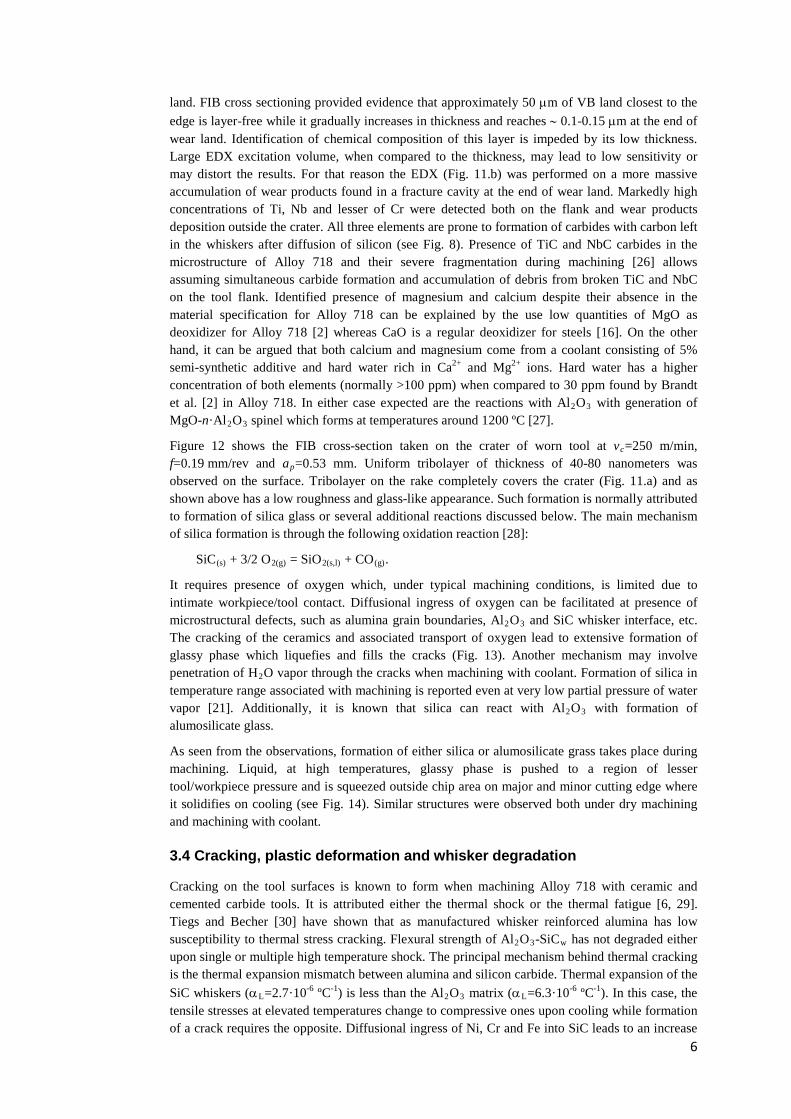
land. FIB cross sectioning provided evidence that approximately 50 µm of VB land closest to the edge is layer-free while it gradually increases in thickness and reaches ∼ 0.1-0.15 µm at the end of wear land. Identification of chemical composition of this layer is impeded by its low thickness. Large EDX excitation volume, when compared to the thickness, may lead to low sensitivity or may distort the results. For that reason the EDX (Fig. 11.b) was performed on a more massive accumulation of wear products found in a fracture cavity at the end of wear land. Markedly high concentrations of Ti, Nb and lesser of Cr were detected both on the flank and wear products deposition outside the crater. All three elements are prone to formation of carbides with carbon left in the whiskers after diffusion of silicon (see Fig. 8). Presence of TiC and NbC carbides in the microstructure of Alloy 718 and their severe fragmentation during machining [26] allows assuming simultaneous carbide formation and accumulation of debris from broken TiC and NbC on the tool flank. Identified presence of magnesium and calcium despite their absence in the material specification for Alloy 718 can be explained by the use low quantities of MgO as deoxidizer for Alloy 718 [2] whereas CaO is a regular deoxidizer for steels [16]. On the other hand, it can be argued that both calcium and magnesium come from a coolant consisting of 5% semi-synthetic additive and hard water rich in Ca2+ and Mg2+ ions. Hard water has a higher concentration of both elements (normally >100 ppm) when compared to 30 ppm found by Brandt et al. [2] in Alloy 718. In either case expected are the reactions with Al2O3 with generation of MgO-n·Al2O3 spinel which forms at temperatures around 1200 ºC [27].
Figure 12 shows the FIB cross-section taken on the crater of worn tool at vc=250 m/min, f=0.19 mm/rev and ap=0.53 mm. Uniform tribolayer of thickness of 40-80 nanometers was observed on the surface. Tribolayer on the rake completely covers the crater (Fig. 11.a) and as shown above has a low roughness and glass-like appearance. Such formation is normally attributed to formation of silica glass or several additional reactions discussed below. The main mechanism of silica formation is through the following oxidation reaction [28]:
SiC(s) + 3/2 O2(g) = SiO2(s,l) + CO(g).
It requires presence of oxygen which, under typical machining conditions, is limited due to intimate workpiece/tool contact. Diffusional ingress of oxygen can be facilitated at presence of microstructural defects, such as alumina grain boundaries, Al2O3 and SiC whisker interface, etc. The cracking of the ceramics and associated transport of oxygen lead to extensive formation of glassy phase which liquefies and fills the cracks (Fig. 13). Another mechanism may involve penetration of H2O vapor through the cracks when machining with coolant. Formation of silica in temperature range associated with machining is reported even at very low partial pressure of water vapor [21]. Additionally, it is known that silica can react with Al2O3 with formation of alumosilicate glass.
As seen from the observations, formation of either silica or alumosilicate grass takes place during machining. Liquid, at high temperatures, glassy phase is pushed to a region of lesser tool/workpiece pressure and is squeezed outside chip area on major and minor cutting edge where it solidifies on cooling (see Fig. 14). Similar structures were observed both under dry machining and machining with coolant.
3.4 Cracking, plastic deformation and whisker degradation
Cracking on the tool surfaces is known to form when machining Alloy 718 with ceramic and cemented carbide tools. It is attributed either the thermal shock or the thermal fatigue [6, 29]. Tiegs and Becher [30] have shown that as manufactured whisker reinforced alumina has low susceptibility to thermal stress cracking. Flexural strength of Al2O3-SiCw has not degraded either upon single or multiple high temperature shock. The principal mechanism behind thermal cracking is the thermal expansion mismatch between alumina and silicon carbide. Thermal expansion of the SiC whiskers (αL=2.7·10-6 ºC-1) is less than the Al2O3 matrix (αL=6.3·10-6 ºC-1). In this case, the tensile stresses at elevated temperatures change to compressive ones upon cooling while formation of a crack requires the opposite. Diffusional ingress of Ni, Cr and Fe into SiC leads to an increase
6
in thermal expansion coefficient for whiskers and therefore promotes cracking (see Fig. 15.a) through formation of tensile stresses upon cooling.
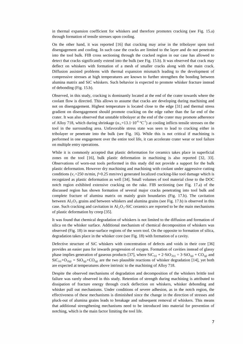
On the other hand, it was reported [16] that cracking may arise in the tribolayer upon tool disengagement and cooling. In such case the cracks are limited to the layer and do not penetrate into the tool bulk. FIB cross sectioning through the cracked region in our case has allowed to detect that cracks significantly extend into the bulk (see Fig. 15.b). It was observed that crack may deflect on whiskers with formation of a mesh of smaller cracks along with the main crack. Diffusion assisted problems with thermal expansion mismatch leading to the development of compressive stresses at high temperatures are known to further strengthen the bonding between alumina matrix and SiC whiskers. Such behavior is expected to promote whisker fracture instead of debonding (Fig. 15.b).
Observed, in this study, cracking is dominantly located at the end of the crater towards where the coolant flow is directed. This allows to assume that cracks are developing during machining and not on disengagement. Highest temperature is located close to the edge [31] and thermal stress gradient on disengagement should promote cracking on the edge rather than the far end of the crater. It was also observed that unstable tribolayer at the end of the crater may promote adherence of Alloy 718, which during shrinkage (αL=13.1·10-6 ºC-1) at cooling inflicts tensile stresses on the tool in the surrounding area. Unfavorable stress state was seen to lead to cracking either in tribolayer or penetrate into the bulk (see Fig. 16). While this is not critical if machining is performed in one engagement over the entire tool life, it can accelerate crater wear or tool failure on multiple entry operations.
While it is commonly accepted that plastic deformation for ceramics takes place in superficial zones on the tool [16], bulk plastic deformation in machining is also reported [32, 33]. Observations of worn-out tools performed in this study did not provide a support for the bulk plastic deformation. However dry machining and machining with coolant under aggressive cutting conditions (vc=250 m/min, f=0.25 mm/rev) generated localized cracking-like tool damage which is recognized as plastic deformation as well [34]. Small volumes of tool material close to the DOC notch region exhibited extensive cracking on the rake. FIB sectioning (see Fig. 17.a) of the discussed region has shown formation of several major cracks penetrating into tool bulk and complete fracture of alumina matrix on mainly grain boundaries (Fig. 17.b). The cavitation between Al2O3 grains and between whiskers and alumina grains (see Fig. 17.b) is observed in this case. Such cracking and cavitation in Al2O3-SiC ceramics are reported to be the main mechanisms of plastic deformation by creep [35].
It was found that chemical degradation of whiskers is not limited to the diffusion and formation of silica on the whisker surface. Additional mechanism of chemical decomposition of whiskers was observed (Fig. 18) in near-surface regions of the worn tool. On the opposite to formation of silica, degradation takes place in the whisker core (see Fig. 18) with formation of a cavity.
Defective structure of SiC whiskers with concentration of defects and voids in their core [36] provides an easier pass for inwards progression of oxygen. Formation of cavities instead of glassy phase implies generation of gaseous products [37], where SiC(s) + 2·SiO2(s) = 3·SiO(g) + CO(g) and SiC(s)+O2(g) = SiO(g)+CO(g) are the two plausible reactions of whisker degradation [14], yet both are expected at temperatures above intrinsic to the machining of Alloy 718.
Despite the observed mechanisms of degradation and decomposition of the whiskers brittle tool failure was rarely observed in this study. Retention of strength during machining is attributed to dissipation of fracture energy through crack deflection on whiskers, whisker debonding and whisker pull out mechanisms. Under conditions of severe adhesion, as in the notch region, the effectiveness of these mechanisms is diminished since the change in the direction of stresses and pluck-out of alumina grains leads to breakage and subsequent removal of whiskers. This means that additional strengthening mechanisms need to be introduced into material for prevention of notching, which is the main factor limiting the tool life.
7

4 Conclusions The present work reflects the results of a comprehensive study on wear mechanisms of SiC
whisker reinforced alumina tools used for machining of aged Alloy 718 under a wide range of cutting data and under dry and wet cuts. Scanning electron microscopy was used for characterization of morphology of worn-out tools. Focused ion beam cross sectioning and lamellae preparation accompanied by EDX were applied for detection of mechanisms of chemical wear and diffusion.
Wear in the major notch was found to consist of two zones with different wear mechanisms. DOC notch is governed by the tool stress state and burr formation while secondary notch was attributed to adhesive wear associated with adverse chip flow. Wear by attrition against defects generated on the machined surface was identified as the principal mechanism of formation of minor notch.
Identified diffusion of Ni, Fe and Cr into SiC whiskers led to their partial or complete degradation. Furthermore, diffusion-assisted thermal expansion mismatch in the tool material is responsible for cracking of the tool rake. Chemical reactions of Al2O3-SiCw ceramics with workpiece material and environment and formation of Ti, Nb and Cr carbides were observed. Abrasive removal of these reaction products was found to govern wear mechanisms on the flank. Together with the above mechanisms, oxidation of whiskers and formation of glassy silica or alumosilicate phase was found to be the dominant wear mechanism on the tool rake. Localized plastic deformation of the tool material was detected under conditions of high thermal and mechanical loads.
Acknowledgements
This work has been done as a part of the research project ShortCut, SSF/Proviking as well as a part of the Sustainable Production Initiative (SPI). Support of Siemens Industrial Turbomachinery AB is greatly appreciated. One of the authors wishes to acknowledge research scholarship granted by Swedish Institute.
References
1. Kitagawa T, Kubo A, Maekawa K (1997) Temperature and wear of cutting tools in high-speed machining of Inconel 718 and Ti-6Al-6V-2Sn. Wear 202:142-148
2. Brandt G, Gerendas A, Mikus M (1990) Wear mechanisms of ceramic cutting tools when machining ferrous and non-ferrous alloys. J European Ceramic Society 6:273-290
3. Ezugwu EO, Bonney J, Olajire KA (2002) Evaluation of the machinability of nickel-base, Inconel 718, alloy with nano-ceramic cutting tools. Tribology Transactions 45:506-511
4. Slama C, Abdellaoui M (2000) Structural characterization of the aged Inconel 718. J Alloys and Compounds 306:277-284
5. Vigneau J, Boulanger JJ (1982) Behaviour of ceramic tools during the machining of nickel base alloys. Annals CIRP 31:35-39
6. Altin A, Nalbant M, Taskesen A (2007) The effects of cutting speed on tool wear and tool life when machining Inconel 718 with ceramic tools. Materials and Design 28:2518-2522
7. Thangaraj AR, Weinmann KJ (1991) On the wear mechanisms and cutting performance of silicon carbide whisker-reinforced alumina. J Engineering for Industry 114:301-308
8

8. Coelho RT, et al. (2004) Some effects of the cutting edge preparation and geometric modifications when turning Inconel 718TM at high cutting speeds. J Mater Proces Technol 148:147-153
9. Narutaki N, Yamane Y, Hayashi K, Kitagawa T (1993) High-Speed Machining of Inconel 718 with ceramic tools. Annals CIRP 42:103-106
10. Sharman ARC, Hughes JI, Ridgeway K (2004) Workpiece surface integrity and tool life issues when turning Inconel 718TM nickel based superalloy. Machining Science Technol 8:399-414
11. Vigneau J, Bordel P, Leonard A (1987) Influence of the microstructure of the composite ceramic tools on their performance when machining nickel alloys. Annals CIRP 36:13-16
12. Gatto A, Iuliano L (1994) Chip formation analysis in high speed machining of a nickel base supperalloy with silicon carbide whisker-reinforced alumina. Int J Mach Tools Manufact 34:1147-1161
13. Xiao M, He N, Li L (2010) Modeling notch wear of ceramic tool in high speed machining of nickel-based superalloy. J Wuhan University Technol 25:78-83
14. Garnier V, et al. (2005) Influence of SiC whisker morphology and nature of SiC/Al2O3 interface on thermomechanical properties of SiC reinforced Al2O3 composites. J Eur Cer Soc 25:3485-3493
15. Chou YK, Song H (2004) Tool nose radius effects on finish hard turning. J Mater Proces Technol 148:259–268
16. Barry J, Byrne G (2001) Cutting tool wear in the machining of hardened steels. Part I: alumina/TiC cutting tool wear. Wear 247:139-151
17. Barrett R, Page TF (1990) The interactions of an Al2O3-SiC-whisker-reinforced composite ceramic with liquid metals. Wear 138:225-237
18. Brandt G, Mikus M (1987) An electron microprobe and cathodoluminescence study of chemical reactions between tool and workpiece when turning steel with alumina-based ceramics. Wear 115:243-263
19. Jahanmir S (2002) Wear transitions and tribochemical reactions in ceramics. Proc Instn Mech Engrs: J. Eng Tribology 216:371-385
20. Yang J-M, Tiegs TN (1995) Strength and Toughness of Ceramic Composites at Elevated Temperatures. In: Nair S, Jakus K (ed) High Temperature Mechanical Behaviour of Ceramic Composites, Butterworth-Heinemann, pp. 87–119
21. Kim H-E, Moorhead AJ (1991) Corrosion and Strength of SiC-whisker-reinforced alumina exposed at high temperatures to H2-H2O atmospheres. J Am Ceram Soc 74:1354-1359
22. Devilez A, et al. (2007) Cutting forces and wear in dry machining of Inconel 718 with coated carbide tools. Wear 262:931-942
23. Arunachalam R, Mannan MA (2000) Machinability of Nickel-based high temperature alloys. Machin Science Technol 4:127-168
24. Jianxin D, et al. (2005) Failure mechanisms of TiB2 particle and SiC whisker reinforced Al2O3 ceramic cutting tools when machining nickel-based alloys. Int J Mach Tools Manufact 45:1393-1401
25. Goh GKL, Lim LC, Rahman M, Lim SC (1997) Effect of grain size on wear behaviour of alumina cutting tools. Wear 206:24-32
26. Zhou JM, Bushlya V, Stahl JE (2011) Investigation on surface damage in high speed turning of Inconel 718 with whisker reinforced ceramic tool. J Mater Proces Technol 212:372-384
27. Lin CC, et al. (2004) Phase evolution in silicon carbide-whisker-reinforced mullite/zirconia composite during long-term oxidation at 1000° to 1350° C. J Am Ceram Soc 83:1797-1803
9

28. Luthra KL, Park HD (1990) Oxidation of silicon carbide-reinforced oxide-matrix composites at 1375° to 1575° C. J Am Ceram Soc 73:1014-1023
29. Thakur DG, Ramamoorthy B, Vijayraghavan L (2009) Machinability investigation of Inconel 718 in high-speed tuning. Int J Adv Manuf Technol 45:421-429
30. Tiegs TN, Becher PF (1987) Thermal shock behavior of an Alumina-SiC whisker composite. J Am Ceram Soc 70:109-111
31. Smart EF, Trent EM (1975) Temperature distribution in tools used for cutting iron, titanium and nickel. Int J Prod Res 13:265-290
32. Goh GKL, Lim LC, Rahman M, Lim SC (1996) Transitions in wear mechanisms of alumina cutting tools. Wear 201:199-208
33. Lo Casto S, et al. (1999) Ceramic materials wear mechanisms when cutting nickel-based alloys. Wear 225-229:227-233
34. Zhao J, et al. (1997) Failure mechanisms of a whisker-reinforced ceramic tool when machining nickel-based alloy. Wear 208:220-225
35. De Arellamo-Lopez AR, et al. (1993) Plastic deformation mechanisms in SiC-whisker-reinforced alumina. J Am Ceram Soc 76:1425-1432
36. Nutt SR (1984) Defects in Silicon Carbide Whiskers. J Am Ceram Soc 67:428-431
37. Karunanithy S (1989) Chemical processes that degrade composites of alumina with SiC whiskers. Mater Science Eng A112:225-231
10

Figures
Fig. 1 Typical morphology of worn-out insert (vc=250 m/min, f=0.19 mm/rev, ap=0.53 mm)
Fig. 2 Formation of two notches on the major cutting edge (vc=250 m/min, ap=0.53 mm, f=0.3 mm/rev)
Fig. 3 (a) Formation of major notch and (b) Chip adhesion on the tool flank (vc=250 m/min, dry machining)
11

Fig. 4 (c) Segmented chips (vc=250 m/min, VBmax=0.17 mm, coolant) and (b) Formation of the secondary notch by chip attrition (vc=200 m/min, coolant)
Fig. 5 (a) Build-up edge of Alloy 718 with removed tool material and (b) respective EDX
Fig. 6 (a) Formation of plastic flow and (b) Side flow on the machined surface
12

Fig. 7 Minor notch due to abrasion between tool flank and machined surface (vc=300 m/min, f=0.15 mm/rev, ap=0.53 mm)
Fig. 8 EDX map of diffusion of elements from Alloy 718 into the tool material
Fig. 9 Diffusional degradation of SiC whiskers on the crater
13

Fig. 10 Variation in thickness of diffusion zone along the crater (vc=250 m/min, f=0.3 mm/rev)
Fig. 11 (a) Adherent layer on the tool flank after chemical etching (vc=250 m/min, f=0.13 mm/rev) and (b) EDX spectra on the wear products accumulated in the fracture on the flank wear (vc=250 m/min, f=0.17 mm/rev)
Fig. 12 FIB cross-section of the tribolayer on the crater of worn tool
14

Fig. 13 Formation of glassy phase in the near-surface region of the crater
Fig. 14 Liquefied tribolayer on the minor cutting edge side of the crater (vc=250 m/min, f=0.25 mm/rev)
Fig. 15 (a) Cracking on the crater and (b) propagation of the crack into the tool bulk
15

Fig. 16 Adherent Alloy 718 on the crater and associated cracking
Fig. 17 (a) FIB cross-section of plastically deformed zone with (b) Crack network of in the alumina matrix
Fig. 18 Chemical decomposition in the core of SiC whiskers
16

Tables
Table 1 Chemical composition of Alloy 718 in wt.%
Elem. Ni Cr Mo Nb Ti Al Co Mn Si Cu C Ta Fe min 50.0 17.0 2.8 4.75 0.65 0.2 - - - - - -
bal max 55.0 21.0 3.3 5.50 1.15 0.8 1.0 0.35 0.35 0.3 0.08 0.05
Table 2 Cutting conditions for identification of speed and coolant influence
Type of test vc [m/min] ap [mm] f [mm/rev] Coolant f and ap effect 250 0.22-0.53 0.11-0.27 With coolant vc and f effect 200, 250, 300 0.53 0.11, 0.15, 0.22 With coolant Coolant effect 250, 300 0.31 0.13, 0.17, 0.21 Dry and with coolant
17