
“We Freeze to Please” - NASA · NASA SP-2002-4226 “We Freeze to Please” A History of...
202
NASA SP-2002-4226 “We Freeze to Please” A History of NASA’s Icing Research Tunnel and the Quest for Flight Safety William M. Leary The NASA History Series National Aeronautics and Space Administration Office of External Relations NASA History Office Washington, DC 2002
-
Upload
doannguyet -
Category
Documents
-
view
225 -
download
2
Transcript of “We Freeze to Please” - NASA · NASA SP-2002-4226 “We Freeze to Please” A History of...
NASA SP-2002-4226
“We Freeze to Please”A History of NASA’s Icing Research Tunnel
and the Quest for Flight Safety
William M. Leary
The NASA History Series
National Aeronautics and Space AdministrationOffice of External Relations
NASA History OfficeWashington, DC
2002

Library of Congress Cataloging-in-Publication Data
Leary, William M. (William Matthew), 1934–We freeze to please: a history of NASA’s icing research tunnel and the quest for flight
safety / by William M. Leary.p. cm.—(The NASA history series) (NASA SP ; 2002-4226)
Includes bibliographical references and index.1. Airplanes—Ice prevention—Research—United States—History. 2. Wind tunnels.
3. United States. National Aeronautics and Space Administration—Research. I. Title. II.Series. III. Series: NASA SP ; 2002-4226.
TL557.I3 L43 2002629.132’5214—dc21 2002025511
ii

Contents
Foreword . . . . . . . . . . . . . . . . . . . . . . . . . . . . . . . . . . . . . . . . . . . . . . . . . . . . . . . . . . .v
Preface . . . . . . . . . . . . . . . . . . . . . . . . . . . . . . . . . . . . . . . . . . . . . . . . . . . . . . . . . . . .x
1. The Beginning of Icing Research . . . . . . . . . . . . . . . . . . . . . . . . . . . . . . . . . . . . . .1
2. The IRT Takes Shape . . . . . . . . . . . . . . . . . . . . . . . . . . . . . . . . . . . . . . . . . . . . .19
3. A Golden Age . . . . . . . . . . . . . . . . . . . . . . . . . . . . . . . . . . . . . . . . . . . . . . . . . . .39
4. Industry in the IRT . . . . . . . . . . . . . . . . . . . . . . . . . . . . . . . . . . . . . . . . . . . . . . . .63
5. Back in Business . . . . . . . . . . . . . . . . . . . . . . . . . . . . . . . . . . . . . . . . . . . . . . . .81
6. Full Speed Ahead . . . . . . . . . . . . . . . . . . . . . . . . . . . . . . . . . . . . . . . . . . . . . . .105
7. New Challenges . . . . . . . . . . . . . . . . . . . . . . . . . . . . . . . . . . . . . . . . . . . . . . . .131
8. The 1990s . . . . . . . . . . . . . . . . . . . . . . . . . . . . . . . . . . . . . . . . . . . . . . . . . . . .149
Essay on Sources . . . . . . . . . . . . . . . . . . . . . . . . . . . . . . . . . . . . . . . . . . . . . . . . . .179
NASA History Series . . . . . . . . . . . . . . . . . . . . . . . . . . . . . . . . . . . . . . . . . . . . . . . .183
Index . . . . . . . . . . . . . . . . . . . . . . . . . . . . . . . . . . . . . . . . . . . . . . . . . . . . . . . . . . . .193
iii

FOREWORD
In 1978, something wholly unexpected happened at what was then the NASA Lewis(now Glenn) Research Center—a “new” aircraft icing program was started. The storygoes something like this: Milt Beheim, chief of the Wind Tunnel and Flight Division,was put in charge of the nearly defunct Icing Research Tunnel (IRT). It was in a state ofserious disrepair, and no NASA program needed it. Industry used it sporadically. Apropulsion and power laboratory, Lewis Research Center (LeRC) no longer had muchinterest in aircraft icing. Many influential people at LeRC were veterans of the success-ful NACA icing program of the 1940s and 1950s, and thus thought they had solved theicing problem a long time ago.
So what should Milt do with the IRT? In typical Beheim fashion, he researched air-craft icing, studied reports, and contacted U.S. aerospace companies and other civil andmilitary government agencies. With encouragement and help from those contacts, heorganized an International Workshop in Aircraft Icing in July 1978 at LeRC.
As you will read in this book, the workshop fully endorsed NASA’s getting back intoaircraft icing. Times had changed, the participants said. Growing commuter marketsinsisted on dependable flight schedules; an expanding private aircraft fleet wanted“all weather” capability for their expensive investment; military and civilian helicoptersneeded rotor-blade ice protection; the large transport aircraft sought more energy-efficient systems; and it was time to apply modern computers and instrumentation to theicing problem. Milt became a believer, and, to the surprise of many old “icingologists,”he won the day by gaining approval to form a new Aircraft Icing Section in his division.Through the competitive process, I was selected to head this new section.
Over the next couple of years, we spent many hours visiting the offices at NASAHeadquarters seeking funding for the new section. When the opportunity later arose,Milt organized a successful effort to finance the first major upgrade of the IRT. With thatupgrade, the IRT went from LeRC’s most humble facility to its most modern wind tun-nel, a prototype for future upgrades to its other tunnels.
That first IRT upgrade could not have been more timely. On 13 January 1982, theAir Florida flight 90 accident at Washington National Airport alerted the nation to thelethal hazards of ground icing and influenced NASA’s decision to approve the first
v

upgrade to the IRT. Shortly after the upgrade was complete, the Boeing Airplane Co.,the FAA, the Association of European Airlines, and the fluids manufacturers approachedus about conducting an extensive joint test program in the IRT to evaluate the effects ofground de-icing/anti-icing fluids on takeoff aerodynamics. We eagerly agreed to this cru-cial international safety program. We knew that the upgraded IRT, with its moderncontrol systems, could do the job. The IRT and its test crews performed flawlessly,prompting the Boeing engineers to remark that the IRT productivity was at least as highas their best performing wind tunnels. The IRT test results formed the basis for newground de-icing regulations, which the FAA promptly promulgated to the air trans-portation industry. That winter, following the IRT tests, the airline industry was usingthe newly tested and approved fluids.
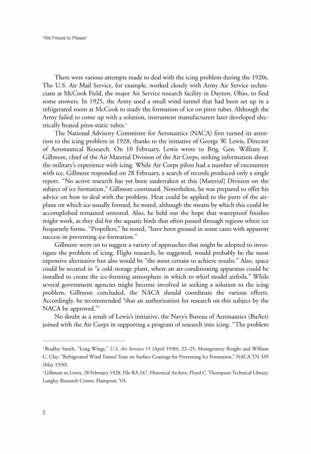
The aerospace community came to regard the IRT as a unique nationalresource. In 1987, the American Society of Mechanical Engineers designated the IRT an“International Historic Mechanical Engineering Landmark” for its leading role in mak-ing aviation safer for everyone. When I retired from NASA in 1994, the IRT had longbeen one of NASA’s most heavily used windtunnels. Its annual test time of about 1,000hours was divided nearly equally between government research and industrial develop-ment. In 2002, nearly 24 years after its “new” start, the IRT is now NASA’s busiest windtunnel. The new icing program began with three NASA-funded study contracts, in which theU.S. aerospace industry told us what it needed. We, in turn, set up a program to addressall of those needs. Its key objectives were as follows: 1. Develop computer codes that would: a) predict water droplet collection on air-
craft surfaces, b) model the ice buildup on aircraft surfaces, and c) provide design tools for various ice-protection systems.
2. Assess and, where appropriate, experimentally evaluate some recently proposed ice-protection systems, such as microwave systems and electro-impulse systems. Fund the development of new ice-protection concepts through the proof of principle stage.
3. Assess and, where appropriate, experimentally evaluate new icing instruments for the detection of ice on aircraft and the measurement of super-cooled cloud properties in flight. Fund the development of new icing instruments and their calibration procedures through the proof of principle stage.
4. Upgrade the IRT to provide improved control of the air speed, air temperature, and super-cooled cloud properties.
5. Conduct aircraft flight tests to assess the effects of ice accretion on aircraft per-formance, to ensure that IRT test results accurately simulate natural icing, and to extend the existing database on the physical properties of super-cooled icing clouds. The aircraft should be fully instrumented for aircraft performance measurements and for cloud property measurements.
vi
“We Freeze to Please”

Although the three study contracts formed the foundation of our icing program, itevolved further through frequent NASA-industry workshops and peer reviews. Industryor other government agencies often proposed programs to address urgent technology orsafety needs. With such a diverse and extensive list of objectives, it was clear that NASAcould not singlehandedly support this large effort in either funding or staff. So we did itby coordinating personnel, test equipment, and experimental facilities within the U.S.government, industry, universities, and, on occasion, within other countries. We wroteinteragency agreements with the FAA, Army, Navy, and Air Force. We also forged inter-national agreements in icing with Canada, France, and the United Kingdom. Some ofthese interagency agreements were accompanied by fund transfers to NASA, and thesewere an important part of our total funding picture. Another important source of fundswas the SBIR (small business innovative research) program at LeRC, through whichnearly all of our advanced ice-protection concepts were funded.
A good example of coordination that required both national and internationalresources was the program to evaluate pneumatic boots for helicopter rotors. TheBFGoodrich Company supplied pneumatic boots and system hardware for IRT modeltests and helicopter flight tests, and participated in all tests. The U.S. Army supplied aUH-1H helicopter, its pilots, and its support crews for all flight tests. The Bell HelicopterCompany supplied experienced test engineers to assess any safety hazards and to followall tests. Canada supplied its Hover Icing Spray Rig. The U.S. Army supplied their in-flight icing simulator Helicopter Icing Spray System (HISS), a custom CH-47 heavy-lifthelicopter fitted with water tanks and spray bars, and all the support aircraft and crews.NASA helped calibrate the HISS by flying its heavily instrumented Twin Otter in thesuper-cooled cloud behind the HISS. The program began with NASA testing severalboot configurations in the IRT to determine the best tube arrangement for effective iceremoval and minimal drag increase. Then Army personnel flew the UH-1H in clear airto evaluate the effects of the inflated boots on helicopter handling qualities. Next theyflew hover tests in Canada’s Hover Icing Spray Rig. Then they flew behind the HISS atEdwards Air Force Base in California. Again they flew in natural icing in Minnesota.Finally, the Army tested the boots on a UH-1H in its special rain and sand erosion facil-ity at Fort Rucker, Alabama.
By coordinating and sharing our resources, we became a close-knit icingcommunity in which good communications flourished. Industry and government agen-cies got test results promptly, because they participated in the tests. Master’s and doctoralstudents worked closely with industry to ensure their NASA grant research was relevantand that our new NASA computer codes gained wide distribution.
With our “new” program came the heavy development of computer codes.These included droplet trajectory codes, ice-accretion modeling codes, and ice-protection system design codes. These highly useful codes have been distributed widely
vii
Foreword

throughout industry and government. Hundreds of engineers use the LEWICE ice-accretion modeling code, and the FAA now accepts it as part of their icing certificationprocess. NASA continues to improve these codes and verify them against experimentaldata. Because of our close ties with the European icing community, they too are familiarwith LEWICE and our other codes—a favorable situation for those U.S. airplane man-ufacturers who must certify their products in Europe.
Although we developed several new ice-protection and ice-detection conceptsearly on, mainly through SBIR contracts, industry did not adopt any initially. But afterI retired and Tom Bond became the branch chief, his team succeeded, via an SBIR con-tract, in getting a new aircraft ice-protection system approved by the FAA in 2001. It wasthe first new ice-protection system approved by the FAA in 40 years! The system, builtby Cox & Company, Inc., New York, NY, is a hybrid that uses both thermal anti-icingand electro-mechanical expulsion de-icing. The system is adaptable and uses much lessenergy than other systems that provide equivalent protection. The system is in produc-tion for Raytheon Aircraft’s Premier I business jet.
Another internationally recognized contribution of Tom Bond’s branch is pilot edu-cation for improved flight safety in icing conditions. NASA has made three pilot trainingvideos and one training CD (compact disk). These widely distributed videos and CDsaddress the icing environment, flight preparedness and strategies for avoiding icing con-ditions, stall due to tailplane ice, and loss of control due to wing ice. According to TomBond, “The tail stall recovery techniques developed in the Tailplane Icing Program haveresulted in averted accidents and saved lives. NASA has received numerous accounts ofpilots who have used these operational procedures and successfully prevented a loss ofcontrol due to a tail stall.”
For 10 years, Tom Ratvasky has been the technical program manager and lead flightresearch engineer on NASA’s icing flight research aircraft. The American Institute ofAeronautics and Astronautics recognized Mr. Ratvasky’s leadership in conceiving andproducing these instructional materials by awarding him the prestigious 2002 LoseyAtmospheric Science Award.
I believe that we can say with pride that the “new” aircraft icing program at GlennResearch Center has continued the tradition of the “old” program by contributing valu-able technological and safety support to the aircraft industry.
One final note: the title of this book, “We Freeze to Please,” was the brainchild ofMr. Al Dalgleish, a branch chief in the Test Installations Division. He used to answer thetelephone by saying “Icing Research Tunnel, where we freeze to please.” Besides being aplay on words, it was Al’s way of saying “we will cooperate with you to get your jobdone.” The “We Freeze to Please” logo made its way onto the IRT baseball caps. Nearlyeveryone who tested in the IRT went home with an IRT baseball cap. Visitors from othercountries took them home. The logo sent the message far and wide that the IRT staff was
viii
“We Freeze to Please”

there to help. As you read this book, you will surely be struck by the pride and esprit ofthe IRT operators, operations engineers, and research engineers. This hardworking andproductive staff made my association with icing a pleasure. I thank you one and all.
-John J. (Jack) ReinmannCleveland, OhioApril 2002
ix
A part of the NASA History Series

Preface
Icing research has received only limited attention from historians. Yet the problemof icing has challenged aviators and aircraft manufacturers since the earliest days of pow-ered flight—and continues to do so. At various times in the past, victory has beendeclared over the menace of icing, but these claims have always proved premature.Despite more than seven decades of research into the phenomena, much remains to belearned about the nature of icing and how best to respond to it.
In the United States, the National Advisory Committee for Aeronautics(NACA) and its successor, the National Aeronautics and Space Administration(NASA), have led the way in investigating the interaction between aircraft and theicing environment, as well as in developing various means to protect fixed- androtary-wing machines. To be sure, icing research has never been given a high priority.When the NACA began to investigate icing during the 1930s, most of the engineersat the Langley Memorial Aeronautical Laboratory were far more interested inadvances in aerodynamics than they were in icing. When work shifted to the newAircraft Engine Research Laboratory in Cleveland in the 1940s, icing research rep-resented only a minor interest of a laboratory that was devoted to enginedevelopment. Later, the demands of the space age overshadowed NASA’s work onaeronautics. Within this limited context, icing investigations usually ranked low onthe aeronautical research agenda.
Perhaps because of their lack of status in the NACA/NASA world, icing researcherstended to form a close-knit group. Untroubled by distinctions between fundamentalresearch and practical engineering, they believed that they were doing important workand were making a significant contribution to safety. They found other icing enthusi-asts in industry, academia, and government agencies, both in the United States andabroad, and eventually came together in an international “icing community.”
Esprit de corps among individuals concerned with icing problems tended to be high.Over and over again during the course of my research for this study, interviewees wouldtell me that their association with icing research was the highpoint of their careers. Theirattitude was infectious, making my work not only a learning experience, but also anenjoyable one.
In telling the story of NACA/NASA icing research, I have focused on the role of theIcing Research Tunnel (IRT) at the Cleveland laboratory. Because the experiments thatwere conducted in the IRT formed only part of a broader investigation into icing whichencompassed flight research and computer simulation, I have included informationabout these topics while keeping the tunnel at the center of my study. Also, I haveattempted to place the work of the NACA/NASA in the broader context of the icingproblems faced by the international aviation community.
x
“We Freeze to Please”

I have been assisted by many people along the way. Kenneth E. Zaremba, now man-agement analyst at the Glenn Research Center, first had the idea for a book on icingresearch and persuaded NASA Headquarters to support the project. Susan L. Kevdzija,IRT facility manager and enthusiastic supporter from the beginning, hosted my first visitto Glenn and opened many doors for me. William P. Sexton conducted a tour of theicing tunnel and shared with me his deep affection for the facility. Robert F. Ide kindlyallowed me to observe the operation of the tunnel during a calibration run.
Kevin P. Coleman, history coordinator at Glenn, looked after my care and feedingduring visits to the laboratory, and I am grateful to him. Laura M. Bagnell and Mary E.Carson of the Imaging Technology Center opened to me the rich photographic collec-tion at Glenn. During a visit to the NASA History Office in Washington, Jane H. Odomfacilitated my access to icing records and made my brief stay in the office a most pleas-ant one. Also at Headquarters, NASA chief historian Roger D. Launius extended his fullsupport to the project, and I am grateful to him.
Edmund Preston, historian at the Federal Aviation Administration (FAA) and anold friend, always promptly responded to my requests for FAA material. Another oldfriend, Michael H. Gorn, took time during a personal tragedy to send me a draft of hisnow published study of flight research at the NACA and NASA. H. Garland Gougerand Erik Conway made my visit to the archives at the Langley Research Center a mostrewarding experience.
Bonita S. Smith, InDyne, Inc., employee and archivist/historian at the Glenn Center,has been my strong right arm throughout the research for this book. An accomplishedarchivist, she has searched for documents, located obscure technical reports, arranged inter-views, located retired employees, and cheerfully responded to a thousand and one requests.Without her assistance, this study would have taken far longer—and might never have beenfinished. I cannot thank her enough.
Thanks are also due to the professionals at NASA Headquarters who made this bookphysically possible. In the NASA History Office, Louise Alstork edited the manuscriptand prepared the index. In the Printing and Design Office, Joel Vendette and SteveOberti expertly laid out the book, Michelle Cheston carefully edited it, and David Dixonhandled the printing. My sincere appreciation goes out to all these people.
The many individuals who submitted to interviews, wrote letters and e-mails, pro-vided material from their personal files, and generally contributed substantially tomaking their study possible are listed in the Essay on Sources. While I am grateful to allof them, I should note that John J. Reinmann took a special interest in the project andspent a great deal of time attempting to educate me on the nature of icing research. As Imanaged to avoid physics and chemistry in high school, this was no small task.
In writing this book, my fondest hope is that I have done justice to the efforts ofthe many men and women who have devoted a substantial portion of their lives todefeating the menace of icing and making the skies safer for us all.
William M. LearyAthens, Georgia xi
A part of the NASA History Series

xii
“We Freeze to Please”

xiii
A part of the NASA History Series

Chapter 1
The Beginning of Icing Research
The dangers posed by icing rarely concerned aviators during the first two decades of poweredflight. Lacking the instruments necessary to fly without visual references, pilots did their best toavoid clouds. As a result, encounters with icing seldom happened and were always inadvertent. Thesituation changed in the mid-1920s when the intrepid aviators of the U.S. Air Mail Serviceattempted to maintain scheduled day-and-night operations between New York and Chicago. Theseinstrument-flying pioneers were the first group of flyers to face the icing menace on a regular basis.As one of their pilots noted at the time about the hazards of the New York-Chicago route, “thegreatest of all our problems is ice.”1
A typical encounter took place during the early morning hours of 23 December 1926.Pilot Warren Williams was en route from Cleveland to Chicago with 321 pounds of mail. Hewas flying underneath an overcast sky until low clouds at Woodville blocked his way. Hedecided to fly on top, as the cloud layer seemed only 1,000-feet thick. He went on instru-ments, monitoring his gyroscopic turn indicator, ball-bank indicator, and airspeed. As theDouglas M4 biplane began to climb, Williams felt his controls grow “mushy.” His turn indi-cator malfunctioned; his compass began to spin; his altimeter unwound. Williams fought thecontrols, but without success. As the ground approached, he cut the throttle and jumped. Hepulled the rip cord on his recently issued parachute and floated down safely from 300 feet.2
Williams was lucky to have survived his encounter with icing. Fellow pilot John F.Milatzo was not as fortunate. Shortly after midnight on 22 April 1927, while en routefrom Chicago to New York with the mail, Milatzo crashed into a field during a severesnow and sleet storm. He was killed.3
1
1 Wesley L. Smith, “Weather Problems Peculiar to the New York-Chicago Airway,” Monthly Weather Review 57
(December 1929): 503–06.2 William M. Leary, Aerial Pioneers: The U.S. Air Mail Service, 1918–1927 (Washington, DC: Smithsonian
Institution Press, 1985), p. 234.3 Ibid., pp. 234–35.
There were various attempts made to deal with the icing problem during the 1920s.The U.S. Air Mail Service, for example, worked closely with Army Air Service techni-cians at McCook Field, the major Air Service research facility in Dayton, Ohio, to findsome answers. In 1925, the Army used a small wind tunnel that had been set up in arefrigerated room at McCook to study the formation of ice on pitot tubes. Although theArmy failed to come up with a solution, instrument manufacturers later developed elec-trically heated pitot-static tubes.4
The National Advisory Committee for Aeronautics (NACA) first turned its atten-tion to the icing problem in 1928, thanks to the initiative of George W. Lewis, Directorof Aeronautical Research. On 10 February, Lewis wrote to Brig. Gen. William E.Gillmore, chief of the Air Material Division of the Air Corps, seeking information aboutthe military’s experience with icing. While Air Corps pilots had a number of encounterswith ice, Gillmore responded on 28 February, a search of records produced only a singlereport. “No active research has yet been undertaken at this [Material] Division on thesubject of ice formation,” Gillmore continued. Nonetheless, he was prepared to offer hisadvice on how to deal with the problem. Heat could be applied to the parts of the air-plane on which ice usually formed, he noted, although the means by which this could beaccomplished remained untested. Also, he held out the hope that waterproof finishesmight work, as they did for the aquatic birds that often passed through regions where icefrequently forms. “Propellers,” he noted, “have been greased in some cases with apparentsuccess in preventing ice formation.”
Gillmore went on to suggest a variety of approaches that might be adopted to inves-tigate the problem of icing. Flight research, he suggested, would probably be the mostexpensive alternative but also would be “the most certain to achieve results.” Also, spacecould be secured in “a cold storage plant, where an air-conditioning apparatus could beinstalled to create the ice-forming atmosphere in which to whirl model airfoils.” Whileseveral government agencies might become involved in seeking a solution to the icingproblem, Gillmore concluded, the NACA should coordinate the various efforts.Accordingly, he recommended “that an authorization for research on this subject by theNACA be approved.”5
No doubt as a result of Lewis’s initiative, the Navy’s Bureau of Aeronautics (BuAer)joined with the Air Corps in supporting a program of research into icing. “The problem
“We Freeze to Please”
2
4 Bradley Smith, “Icing Wings,” U.S. Air Services 15 (April 1930): 22–25; Montgomery Knight and William
C. Clay, “Refrigerated Wind Tunnel Tests on Surface Coatings for Preventing Ice Formation,” NACA TN 339
(May 1930).5 Gillmore to Lewis, 28 February 1928, File RA 247, Historical Archive, Floyd C. Thompson Technical Library,
Langley Research Center, Hampton, VA.
The Beginning of Icing Research
3
1,60
0
1,40
0
1,20
0
1,00
0
800
600
400
200 0
5055
6065
7075
8085
9095
Hours Run Per Year
Yea
r (
CY
)
Lew
is I
cing
Res
earc
h Tu
nnel
Ann
ual U
sage
Figu
re 1
–1.
Lew
is Ic
ing
Res
earc
h Tu
nnel
ann
ual u
sage
.

is one of great interest to Naval aeronautics,” Rear Adm. William A. Moffett, chief ofBuAer, wrote to Lewis on March 12, “and one in which very little data is available. Asolution to this problem is considered to be one of great importance.” Moffett went onto request that the NACA “undertake research on this problem with a view of deter-mining the conditions under which ice forms on the structures of aircraft; second,possible preventative means; and third, the development of an instrument or instrumentswhich would indicate to the pilot conditions of temperature and humidity under whichice formation takes place.”6
One day later, citing Gillmore’s request and anticipating the letter from BuAer,Lewis told the NACA’s Langley Memorial Aeronautical Laboratory (LMAL) inHampton, Virginia, to begin planning an investigation into the icing problem. He notedthat the Department of Commerce, which also had an interest in the subject, had at firstsuggested that the Bureau of Standards erect a small wind tunnel in their altitudechamber and devise a system to control temperature and humidity in order to investigateconditions under which ice would form on metal and fabric surfaces. Upon further con-sideration, however, it had been decided to conduct the preliminary investigation at theLangley laboratory. “This investigation,” Lewis continued, “could be made in the 6-inch wind tunnel, using a small metal airfoil section. The temperature of the airfoil sec-tion could be controlled by the expansion of CO2 . . . and the humidity controlled eitherby water spray in the air stream or by admitting steam in the air stream. [If ] the tem-perature of the air stream could also be controlled by the expansion of the CO2, bylagging the small tunnel with Cellotex or cork, and by placing a box or chamber aroundthe test section, fairly constant conditions could be obtained.”
Lewis hoped that the investigation would produce information on the temperatureand humidity at which ice will form on metal and fabric surfaces, develop an instrumentto alert pilots to conditions under which icing could be expected, and suggest methodsof preventing ice formation “such as heating the wings or coating the wing or surfacewith some material which will prevent deposition of water.”7
Two weeks later, on 28 March, William P. MacCracken, Jr., assistant secretary ofcommerce for aeronautics, called a special conference of representatives of the Army AirCorps, Navy Bureau of Aeronautics, Weather Bureau, Bureau of Standards, and theNACA to study “the causes and prevention of ice formation on aircraft.” Lewis was ableto report at this meeting that the NACA had already begun such a study. Reports frompilots who had experienced icing conditions were being reviewed, and research flightsinto icing were underway. Also, the NACA had plans for tests “in a special wind tunnel
“We Freeze to Please”
4
6 Moffett to Lewis, 12 March 1928, File RA 247, Langley Library.7 Lewis to LMAL, 13 March 1928, RA 247, Langley Library.

in which atmospheric conditions will be simulated.” The day after this meeting, Lewisinformed Langley “that in as much as the National Advisory Committee for Aeronauticshad undertaken this problem and was working on it, [it was agreed that] all activitiesalong this line should be coordinated and should be reported to [the NACA].”8
The final step necessary to formalize the NACA’s investigation into the icingproblem came on 28 June 1928, when the organization’s Executive Committee approvedResearch Authorization (RA) 247, “Ice Formation on Aircraft.” RA 247 declared thepurpose of the investigation was: “To determine the conditions under which ice formson the structures of aircraft; to develop possible means of prevention; and to develop aninstrument or instruments which will indicate to the pilot conditions of temperature andhumidity under which ice formation takes place.”9
Even before approval of the research authorization, NACA chief pilot ThomasCarroll had laid the groundwork for a flight investigation of icing. Carroll had beeninterested in the problem ever since Air Mail Service pilots had begun to report their dif-ficulties with icing. “The most difficult aspect of the matter,” he wrote to Henry J. E.Reid, engineer-in-charge at the Langley Laboratory, on 17 March 1928, “appears to liein an almost total ignorance of the conditions which must exist to produce the phe-nomena and . . . the double difficulty of artificially reproducing the conditions.” Herecommended that the NACA’s Flight Operations section conduct a research programinto inflight icing on a priority basis. To accomplish the task, he wanted “a superchargedairplane” that would be equipped with automatically recording air temperature ther-mometers that also would be visible to the pilot. In addition, he sought “an automaticallydriven motion picture camera placed and focused at short range on certain struts and sur-faces on the airplane to be controlled by the pilot or observer to provide additional datato visual observation.” He proposed to seek out cloud formations with a range of tem-peratures that were conducive to icing. Together with investigating the phenomena oficing, Carroll also wanted to experiment with preventive measures, such as “heat control,oiling, etc.”10
RA 247 meant that Carroll would get his opportunity to investigate icing. TheNACA equipped a Vought VE-7 with small auxiliary surfaces and aerodynamic shapesthat were similar to the struts, wires, pitot heads, and other areas that were vulnerable toicing. Research pilots Carroll and William H. McAvoy set out in search of cloud forma-tions where ice was likely to be encountered. They recognized and described the different
The Beginning of Icing Research
5
8 “Conference at Department of Commerce Regarding Formation of Ice on Aircraft,” 28 March 1928; Lewis
to LMAL, 29 March 1928; both in RA 247, Langley Library.9 Research Authorization 247, copy in RA 247, Langley Library.10 Carroll to H. J. E. Reid, 17 March 1928, RA 247, Langley Library.

types of ice that they found. Glaze ice, which formed at temperatures just below freezing,was clear and tended to protrude from the leading edge of airfoils. Rime ice, on the otherhand, which occurred at lower temperatures and was opaque, usually took on a stream-line shape. Performance penalties, they noted, were caused more by distortions to theshape of the airfoil than by the weight of the ice. Engineers knew, of course, that a cubicfoot of water weighed 62.5 pounds. When water expanded on freezing, the weightdecreased to 56 pounds per cubic foot. Even a biplane, with its wires and struts, wasunlikely to accrete more than seven cubic feet of ice, or some 400 pounds, during themost severe icing conditions. While the added weight would cause some performancepenalties, it would not constitute a dangerous overload.
Aeronautical engineers also knew that air flowing over the upper surface of a wingproduced lift. To ensure that nothing disturbed the even flow of air, the airfoil surfacewas gently rounded. When ice formed on this surface, especially on the leading edge ofthe airfoil, turbulence and eddy currents caused by the non-streamlined shape destroyedlift. At some point, the airfoil would stall, and the airplane would fall out of the sky.
Carroll and McAvoy pointed out that a number of means of preventing or removingthe ice formations had been suggested. The most frequently tried method had been theuse of oil or grease to reduce the adhesion of the ice to vulnerable parts of the airplane.To date, however, the application of oil and grease had failed to produce worthwhileresults. In fact, it seemed that the use of these substances might even hasten the forma-tion of ice. Suggestions had also been made so that engine exhaust heat might be pipedthrough the leading edge of the wing to melt the ice or prevent it from forming—amethod that might be worth further investigation. But given the current state of ice pre-vention, Carroll and McAvoy concluded, “safety . . . obviously lies in avoidance.”11
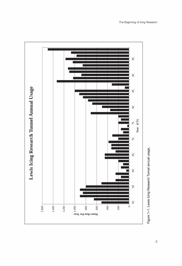
The NACA’s laboratory research also began in 1928 when it placed into operation arefrigerated wind tunnel at Langley. The facility consisted of a metal shell that was insu-lated by layers of cork and wood. Air temperature inside the tunnel was lowered andregulated by brine, which was cooled by a commercial refrigerating apparatus that flowedthrough hollow metal guide vanes. A propeller circulated the air. Water droplets, their sizeregulated by air and water pressure, came through four spray nozzles. Double glass doorsand windows permitted observation and photographs of models in the test chamber.
This first refrigerated icing research tunnel had two main problems. One was itssmall size—the air stream was only 6 inches in diameter. The other major difficultyrelated to the formation of small water droplets. “Considerable time,” the NACA’s
“We Freeze to Please”
6
11 Carroll and McAvoy, “The Formation of Ice Upon Exposed Parts of an Airplane,” NACA TN 293 (1928),
and “The Formation of Ice Upon Airplanes in Flight,” TN 313 (1929). See also Bradley Jones, “Icy Wings,”
U.S. Air Services 15 (April 1930): 22–25.

The Beginning of Icing Research
7
Figu
re 1
–2.
The
NA
CA’
s fir
st R
efrig
erat
ed Ic
ing
Tunn
el,
1930
.

Annual Report for 1929 noted, had been devoted “to means for controlling the amountof water sprayed into the air stream, the size of water particles, and the temperatures ofthe air and water.” Commercial spray nozzles simply could not produce the small waterdroplets that were found in natural icing. Nonetheless, it was possible to use the facilityfor some icing research; although fuller experimental capabilities would come only afterthe construction of an icing research tunnel in the 1940s.12
The first tests in the tunnel employed a section of a Clark Y mahogany airfoil.Widely used in the design of wings for aircraft during the 1920s, the high-lift airfoil fea-tured a 3-inch chord and a 12-inch span. Researchers Montgomery Knight and WilliamC. Clay left half the airfoil bare and brushed the other half with a thin coating of sub-stances designed to retard the formation of ice. They first investigated six insolublecompounds: light and heavy lubricating oil, cup grease, Vaseline, paraffin, and simonizewax. None of the coatings prevented ice from accreting on the model. “The dropsadhered to the surface,” they reported, “especially at the stagnation point of the leadingedge, and [they] froze quite readily as on the bare wing.”
The researchers next tried five soluble substances: glycerin, glycerin and calciumchloride, molasses and calcium chloride, a hardened sugar solution, and a hardened glu-cose solution. The first three were brushed on the airfoil, but the sugar and glucose hadto be boiled down and applied while hot. When they hardened, Knight and Clay noted,they had the consistency of “taffy candy.” The solubles were supposed to dissolve withwater as it struck the airfoil and lower the freezing point so that ice would not form.The glycerin and calcium chlorate solutions, however, immediately blew back from theleading edge and left it bare. The sugar and glucose solutions remained on the airfoil,but ice built up on top of them.
Knight and Clay also tested corn syrup, honey, glycerin soap, commercial paint,and goose grease. All proved disappointing except the White Karo corn syrup, whichseemed to provide some protection against ice accretion and merited further study.Perhaps the most useful information derived from the first of what would prove alengthy quest for ice-phobic materials was the observation that ice formed only on theleading edge of the airfoil in all tests. “Any preventive compound,” they concluded,“need be applied only to that part of the wing to be effective.”13
Flight tests brought more promising results. In June 1931, famed physicistTheodore Theodorsen and researcher William C. Clay reported on the use of engine
“We Freeze to Please”
8
12 Fifteenth Annual Report of the National Advisory Committee for Aeronautics, 1929 (Washington, DC:
Government Printing Office, 1930), pp. 25–26.13 Knight and Clay, “Refrigerated Wind Tunnel Tests on Surface Coatings for Preventing Ice Formation,”
NACA TN 339 (1930).

exhaust heat as a means to prevent ice from forming. They mounted a modified ClarkY airfoil of approximately full-scale dimensions on a Fairchild F-17 monoplane andinserted a small boiler in the engine’s exhaust pipe. Steam passed through a con-ducting pipe and entered the leading edge of the airfoil by means of a distributionpipe equipped with small holes. The researchers mounted spraying jets 4 feet in frontof the airfoil. As the airplane was flown into temperatures as low as 18 °F, water wassprayed on the airfoil.
“The most essential result obtained in this study,” Theodorsen and Clay wrote,“is the fact that ample heat is available in the exhaust and in the cooling water for thepurpose of ice prevention.” The successful design of an airplane immune from thedangers of ice accumulation, they confidently but erroneously predicted, was now“only a matter of technical development.”14
Theodorsen and Clay also used the refrigerated wind tunnel at Langley for theiricing research. After the NACA received reports about gasoline tank vents freezing inflight, the two researchers developed a program to test various configurations in therefrigerated wind tunnel. The primary function of the vents was to maintain the pres-sure inside the gasoline tank approximately equal to that of the atmosphere. The size,position, and location of the vent pipes differed with different types of aircraft, andthe designs seemed “more or less at random.”
The researchers positioned eleven different vent pipes in the test section of therefrigerated wind tunnel. The pipes varied in tube diameter from 0.125-inch to 0.5-inch and in shape from straight to L-shaped to U-shaped. They were subjected to theicing spray until the ends froze over and plugged the vent. Experiments showed thattubes perpendicular to the airstream consistently froze over, with the time required toplug the vent varying with the diameter of the tube. The opening of the tubes pointedaft, however, did not accrete ice.
As a result of their investigation, Theodorsen and Clay were able to make a spe-cific recommendation to manufacturers and operators. A 0.75-inch tube, bent at aright angle and placed with the open end pointed downstream, they concluded,would be “the safest arrangement for gasoline tank vents . . . and also the most prac-tical, with respect to gas tank pressure.” Harry A. Sutton, chief engineer for AmericanAirways, who earlier had reported a problem with the icing of gasoline tank ventpipes, expressed his appreciation to Dr. Lewis for the investigation and reported inOctober 1931 that “we are installing the type of vent recommended in your report.”15
The Beginning of Icing Research
9
14 NACA Report 403 (1933). Although published in 1933, this report was written on 12 June 1931.15 “The Prevention of Ice Formation on Gasoline Tank Vents,” NACA TN 394; Sutton to Lewis, 16 March and
17 October 1931, RA 247, Langley Library.

While the NACA believed that the application of heat eventually would solvethe problem of inflight icing, a more immediate solution seemed at hand during theearly 1930s, thanks primarily to the work of William C. Geer. A retired scientist,Geer had graduated from Cornell University in 1905 with a doctorate in chemistryand joined the BFGoodrich Company of Akron, Ohio, in 1907 as their chiefchemist. In 1927, two years after he had retired from Goodrich due to ill health,Geer became interested in the airplane icing problem. He knew that there had beensporadic research since 1922 on ice-phobic liquids and wing fabrics, but these earlyefforts had produced no satisfactory results. Geer decided to try his own experi-ments. He built a small research laboratory and began to test chemical methods toprevent the formation of ice.16
By 1929, Geer’s work had showed sufficient promise to attract the attention ofthe Daniel Guggenheim Fund for the Promotion of Aeronautics. As part of its grantprogram to enhance aeronautical safety, the Guggenheim Fund gave Geer $10,000 toconduct further research. Working with Dr. Merit Scott of Union College, Geerarranged with the Department of Physics at Cornell to build a small icing researchtunnel. The facility featured a 7-inch by 7-inch test section and a 3-inch circularthroat, with the temperature lowered by ice.17
Tests in the tunnel suggested that oiled rubber sheets that covered the vulnerableparts of the airplane showed considerable promise. Coated with a mixture of 4 partspine, 4 parts diethylthalate, and 1 part castor oil, the rubber sheet retarded the accu-mulation of ice. The major problem was to get rid of the ice that managed to formon the sheet. Working with B. F. Goodrich, Geer came up with an “expanding rubbersheet” or “ice-removing overshoe.” The coated rubber sheet was placed on the leadingedge of an airfoil in the tunnel, and air pressure was used to inflate the sheet andremove the ice.
Practical tests of the device were conducted in late March and April of 1930. WesleySmith, a former Air Mail Service pilot who was now operations manager for National AirTransport, flew three test runs with the overshoe or boot. The test section consisted oflaced-on overshoes that were 36 inches long by 15 inches wide. Two tubes, 2 inches indiameter, supplied air to inflate the boots. During the flights, Goodrich engineer RussellS. Colley sat on an orange crate in the mail compartment of the airplane and used abicycle pump to deliver air into the tubes, alternating from one tube to the other bymeans of a manually operated valve. The boot worked well on a flight from Cleveland to
“We Freeze to Please”
10
16 William C. Geer, “The Ice Hazard on Airplanes,” Aeronautical Engineering 4 (1932): 33–36.17 Ibid.; Richard P. Hallion, Legacy of Flight: The Guggenheim Contribution to American Aviation (Seattle:
University of Washington Press, 1977), pp. 109–10.

Buffalo in heavy icing conditions. The main problem was ice forming on the unprotectedpropeller, which Smith removed by violent sideslips.18
Goodrich was so impressed with the flight tests that he decided to build a large icingresearch tunnel at Akron. By far the largest facility of its kind in the world, the tunnelmeasured 10 feet by 40 feet, with a test chamber 3 feet by 7 feet by 6 feet. Two standard36-inch propellers drew air through cooling pipes, across the test section, and into an exitcone. The propellers were on the same shaft, which extended outside the tunnel to a 15-horsepower motor. Refrigeration was achieved by passing the air over coils—780 feet of1.25-inch pipe—that were cooled by a flood system of liquid ammonia. Airbrush noz-zles used 80 pounds of compressed air to atomize water into a fine mist and simulate anicing cloud. Designed with the assistance of NACA engineers from the Langley labora-tory, the Goodrich tunnel could produce temperatures as low as 0 °F and wind speeds of85 miles per hour.19
The first test in the tunnel took place on 22 August 1930. A Clark Y airfoil,equipped with a prototype two-tube boot, was placed in the test chamber. Withammonia flowing through the coils and the fan turned off, the temperature in the tunnelreached 26 ° after 1.5 hours. The propeller was then started. As the wind speed reached60 miles per hour, the temperature rose slightly. Water, with a temperature of 43 °, wasintroduced into the airstream, producing a slush-type ice. The boot successfully removedseveral coats of ice before the spray nozzles became clogged.20
Although the spray system was never able to produce the small droplets found in anatural icing cloud, the tunnel nonetheless proved a useful research tool. The best wayto deal with accumulated ice, Goodrich discovered following numerous tests in thetunnel, was to inflate the boots three times a minute. Engineers developed a lightweightair pump that was equipped with a valve that would open automatically and inflate theboots. Other work in the tunnel led to overshoes that would protect tail surfaces, strutsand other parts of the airplane that would be vulnerable to icing.21
Early in 1931, Goodrich equipped a Lockheed Vega—Miss Silvertown—with theprotective system that had been developed in the tunnel. Tailored boots were snappedonto the leading edge of the wing, zippered to struts, and laced to tail surfaces. An aircompressor installed on the motor automatically supplied air to the inflatable boots. On
The Beginning of Icing Research
11
18 Geer, “Ice Hazard;” Ben Kastein, “Russell S. Colley, Inventor,” Rubber World, June 1982, pp. 38–40.19 Colley, “Problem #4825: Goodrich Refrigerated Wind Tunnel,” 13 September 1930, The Records of
BFGoodrich Aerospace, Akron, Ohio. The author is indebted to David Sweet of BFGoodrich’s Ice-Protection
Systems Division for this memorandum and for other material relating to Goodrich’s icing research.20 Ibid.21 New York Times, 29 October 1933.

30 March 1931, Charles Meyers flew Miss Silvertown through icing clouds that extendedfrom 2,000 to 8,000 feet over Akron. The system worked perfectly. This flight, the NewYork Times announced the next day, marked “victory” over “one of aviation’s most dan-gerous enemies.”22
Most airlines quickly adopted the Goodrich boots. TWA equipped its NorthropAlpha 4-As with boots on wings and tails in the winter of 1932–33. In the summer of1933, United Airlines ordered boots for its Boeing 247s, while TWA put them on itsDouglas transports during the winter of 1934–35. The airlines encountered and over-came numerous installation problems. The rubber boots, for example, refused to remainattached to airfoil surfaces at high speeds. Goodrich engineer Russell Colley solved thisproblem by inventing a hollow threaded rivet called a Riv-Nut that could be installedfrom outside the wing.23
Goodrich, working in cooperation with I. R. Metcalf of the Bureau of AirCommerce and Walter R. Hamilton of TWA, also used the icing tunnel to develop a pro-peller de-icing system. It consisted of a circular trough of inverted U-section that wasbolted to the rear face of the propeller hub and fitted with short tubes that opened at thebase of the propeller blade. De-icer fluid, usually a mixture of glycerin and alcohol, wasproduced at a pressure of 4–9 pounds from a storage tank inside the cockpit and thendripped into the U-section on the propeller hub. Centrifugal force then carried the fluidalong the bare aluminum alloy blades. Following a long series of flight tests by TWA pilotD. W. Tomlinson, this “slinger ring” arrangement became standard equipment on thenation’s air transports.24
By the winter of 1935–36, most airlines had retrofitted their fleets with the modi-fied Goodrich de-icing system. The total weight of the system, at least on TWA’s Douglastransports, was 177 pounds, and it cost $65,000. This seemed a small price to pay forthe protection against icing. In August 1936, TWA President Jack Frye proclaimed thatresults during the past winter proved that the new de-icing equipment “has served virtu-ally to eliminate ice formation as a danger to scheduled flight.”25
Frye’s optimistic comment would soon come back to haunt him. On 26 March 1937,the front page of the New York Times announced the crash of “a giant TranscontinentalAirways skyliner” the previous evening while attempting to land in Pittsburgh. All thir-
“We Freeze to Please”
12
22 “Goodrich Airplane De-Icers,” Aero Digest 18 (May 1931): 66; New York Times, 13 March 1931.23 Kastein, “Colley.”24 S. Paul Johnson, “Ice,” Aviation 35 (May 1936): 15–19; Jerome Lederer, Safety in the Operation of Air
Transportation (Norwich University, 1939).25 Fred L. Hattoom, “Installation of De-Icer Equipment for Winter Airline Service,” Aero Digest 29 (November
1936): 38, 86; Jack Frye, “No Ice Today,” U.S. Air Services 21 (August 1936): 13–14.

teen passengers and three crewmembers had perished when the DC-2 dove nose first intoa small gully near Clifton, Pennsylvania, 10 miles from Pittsburgh. It did not take inves-tigators long to establish the cause of the accident. Observers who reached the scene of thecrash reported that 1.5 inches of ice remained on the leading edge of the ailerons and onthe wing tips of the shattered airplane, which had not burned. A report of the AccidentBoard of the Bureau of Air Commerce confirmed the initial findings—ice had broughtdown one of TWA’s new transports.26
The TWA crash set in motion a chain of events that would bring the NACA backinto icing research. The committee had done little in this area since 1931. The smallicing tunnel at Langley had rarely been used. The last experiment in the tunnel—a testof an ice-phobic substance—had taken place in August 1935, and there had been noplans for any further use of the facility. The aerodynamicists at Langley did not thinkhighly of the pneumatic boot system, which they believed caused drag. As far as theywere concerned, researchers Theodorsen and Clay had demonstrated in 1931 that theapplication of heat was the answer to the icing problem. The fact that manufacturers hadbeen slow to engineer such a system was not the concern of the NACA.27
In the wake of the TWA accident, however, icing became an issue that the NACAcould not ignore. On 8 April 1937, Paul E. Richter, vice president in charge of opera-tions for TWA, wrote to Rear Adm. A. B. Cook, chief of the Bureau of Aeronautics,seeking his assistance in persuading the NACA “to proceed at the earliest instant with aninvestigation of ice formations which must produce solutions to every aspect of theproblem.” No transport company, Richter emphasized, had “the personnel or facilities toundertake the scientific program necessary to solve this vital problem.”28
Cook was quick to lend his support to Richter’s request. Two weeks later, heinformed Dr. Lewis that despite the NACA’s earlier work, the problem of icing “has notbeen completely solved.” The NACA, therefore, should “continue these investigations,particularly in reference to formations [of ice] on wings and control surfaces.” A suc-cessful solution to the icing problem, he emphasized, had both commercial and militaryvalue and should be given “the highest priority.”29
Lewis forwarded Cook’s letter to engineer-in-charge Reid at Langley. Reid, in turn,sought the views of Smith J. DeFrance, senior aeronautical engineer at the laboratory.
The Beginning of Icing Research
13
26 New York Times, 26 and 27 March and 5 May 1937.27 William C. Clay to Chief, Aerodynamics Division, 28 August 1935; H. J. E. Reid to NACA, 8 April 1937;
Smith J. DeFrance to Engineer-in-Charge, 20 May 1937; all in RA 247, Langley Library.28 Richter to Cook, 8 April 1937, RA 247, Langley Library. In his letter to Cook, Richter noted that he had
sent a similar request to General A. W. Robbins, commanding officer of the Air Corps’ Materiel Division.29 Cook to Lewis, 24 April 1937, RA 247, Langley Library.

DeFrance recommended that any icing tests be conducted in flight. A model airfoil couldbe attached to a research airplane together with a water-spray system so that photographscould be taken of ice formations. Because of the size of the model, the tests could not bedone in the existing refrigerated wind tunnel, and he would not recommend “that alarger tunnel be constructed.” The water-spray method on an airfoil attached to an air-plane, he concluded, would produce better results than tunnel research and would be farmore economical. Reid endorsed DeFrance’s views, which he passed along to Lewis as theposition of the Langley laboratory.30
The Langley laboratory, however, would not have the last word on the matter oficing research. Edward P. Warner, influential chairman of the NACA’s AerodynamicsCommittee, not only wanted the NACA to proceed with an investigation of icing, butalso believed that it should be done with the assistance of a new and larger refrigeratedwind tunnel. With Warner’s strong support, the Aerodynamics Committee recom-mended that a refrigerated wind tunnel be built. Icing, Warner told his colleagues, wasconsidered by many commercial pilots to be their worst problem. The NACA’s ExecutiveCommittee endorsed the recommendation of the Aerodynamics Committee, which wasthen approved by the full Committee on 6 June 1937.31
In mid-June, Lewis visited Langley to discuss “the problem” of a large refrigeratedwind tunnel. The proposed facility, he told DeFrance and Eastman N. Jacobs, wouldaccomplish two purposes. Not only would it be used for icing experiments, but it wouldbe the model for Jacobs’s long-desired low-turbulence variable-density wind tunnel(VDT) as well. Appropriations had been provided in funds for 1939 to build the pres-surized two-dimensional, low-turbulence facility that Jacobs needed for his work withlaminar-flow airfoils. The Bureau of the Budget, however, required complete plans andspecifications for the VDT tunnel by 1 July 1938. Jacobs could use the icing tunnel ashis model to secure the necessary information to design the VDT.32
Construction of the icing tunnel began early in 1938. W. Kemble Johnson recallsbeing asked by construction administrator Edward Raymond Sharp to head a majorproject to build a new wind tunnel at Langley and to modify existing tunnels and otherfacilities. The money for the project, Sharp said, would come from “post-account” funds
“We Freeze to Please”
14
30 DeFrance to Reid, 30 April 1937; Reid to Lewis, 4 May 1937; both in RA 247, Langley Library.31 Lewis to Joseph S. Ames, 26 April 1938, RA 247, Langley Library.32 Lewis to Ames, 26 June 1937, and 26 April 1938; both in RA 247, Langley Library. James R. Hansen,
Engineer in Charge: A History of the Langley Memorial Laboratory, 1917–1958 (NASA SP-4305, 1987),
p. 110, contends that Lewis had always intended the tunnel to be used as a variable-density facility and that
labelling it an icing tunnel had been “a necessary political subterfuge.” There is no indication of this in the
material in RA 247.

and would involve internal resources. The first priority would be the construction of anicing tunnel. Aircraft had been encountering icing problems, Sharp explained toJohnson, and the NACA needed more information about how and when ice formed andwhat could be done to get rid of it.33
Putting up the 100-foot by 200-foot structure to house the icing research tunnel,which would be located behind the Technical Services Building at the Langley laboratory,was no easy task. “We built that from scratch,” Johnson remembered; “I mean, we werepoor people.” He went to nearby Fort Eustis and located steel, trusses, and supportcolumns from a building that had been torn down. The materials were lying in the weeds“with practically trees growing through them.” He had welders straighten out the trusses,then cut off the ends of columns and attach them to other columns in order to get therequired height for the new building.
For insulation, Johnson secured surplus life preservers from the Navy Yard inWashington, DC. He then hired half the local high school football team to open the pre-servers and fluff up the kapok which would be used to insulate the tunnel. “That wasquite a nasty mess,” Johnson noted; “[the workers] had to wear face masks and respira-tors to keep from breathing in dust and fluff from the kapok.”
A simple refrigeration system was devised. Johnson purchased carloads of dry icethat would be used to cool an open tank of ethylene glycol. A fan circulated air throughthe 7-foot by 3-foot test section, while adjustable spray nozzles put water into theairstream.
The cooling system was tried out for the first time on a hot summer’s night in 1938.High schoolers were again on hand— this time to chop up the dry ice. A fog of dry icequickly rose up on the floor of the tunnel to a depth of about 2 feet, with a layer of CO2
on top. Above that was a 0.5-inch-thick layer of mosquitoes. “It was a very weird thing,”Johnson recalled. Nonetheless, the system worked, and the facility had cost only 100,000depression-era dollars.
In April 1938, as the new refrigerated wind tunnel neared completion, Warner andother senior NACA officials had visited Langley to inspect the work that was being doneat the laboratory. As part of their tour, the group was taken to the test chamber of theicing tunnel and treated to a lecture by Jacobs about how the facility would be used as amodel for the new two-dimensional tunnel. This came as news to Warner, who promptlyexpressed his concern to Lewis, “lest the non-turbulent qualities of the icing tunnelobscure the fact that it is an icing tunnel. I appreciate Jacobs’s desire to do in that tunnelthe work for which he finds it so exceptionally well fitted; air transport, at least, needs a
The Beginning of Icing Research
15
33 Interview with W. Kemble Johnson by Michael D. Keller, 27 June 1967, copy in the NASA History Office,
Washington, DC.
solution to the icing problem just now much more than it needs further increases in effi-ciency.” Warner suggested that transport lines be asked for suggestions about the type ofresearch that would be most urgent for them.34
Lewis assured Warner that the work that Jacobs was doing in the tunnel was onlyfor the purpose of obtaining data for the two-dimensional wind tunnel and was not inany way holding up the operation of the icing tunnel, which was set to be ready in July.“I concur with you 100 percent,” Lewis told Warner, “in your remarks concerning theicing tunnel and its use.” The air transport companies would be contacted, and aschedule of icing research would be drawn up.35
Lewis made good on his promise to Warner and solicited suggestions from the air-lines through the Air Transport Association. The airlines responded with a lengthy list ofpossible areas for investigation. American Airlines, for one, envisioned airplane icing teststhat would encompass wings, windshields, struts, propellers, control surfaces, airplaneskin, engines, cabin windows, exterior lights, and ventilating system inlets and outlets.36
As it turned out, the Langley laboratory had its own agenda for tests in the new icingtunnel, and this agenda had little to do with what the airlines wanted to accomplish.Lewis A. Rodert, a junior aeronautical engineer who had joined the NACA in September1936, took the lead in formulating the laboratory’s icing research program. For Rodert,as well as for most of his engineering colleagues at Langley, the answer to the airlineindustry’s icing problems lay in thermal de-icing systems. Existing data indicated thatsufficient exhaust heat was available for de-icing. The problem, Rodert noted, was “oneof distribution.” In order to investigate this aspect of a thermal de-icing system, Rodertwanted to test models in the new icing tunnel. Securing the approval of his superiors, heused three models of 6-foot sections of NACA 23012 airfoils with a 72-inch chord, eachwith a different duct system. An electric heater and three small electric fans circulated hotair through the ducts. With temperatures from 20° to 28°F and a wind speed of 80 milesper hour, he adjusted the spray nozzles to produce water droplets that varied from 0.002to 0.05 inches in diameter. He found that ice could be removed or prevented from
“We Freeze to Please”
16
34 Warner to Lewis, 23 April 1938, RA 247, Langley Library. Jacobs responded to Warner’s criticism. “I must
admit,” he wrote, “I was discouraged and disheartened over learning Mr. Warner’s reaction toward our efforts
to advance wind-tunnel technique as indicated by this new equipment. To me, it appears to represent in many
ways a successful attempt to keep ahead of foreign countries in our research methods, but evidently to him it
inspired a comment no more eloquent than it is an icing tunnel.” Jacobs to Chief, Aerodynamics Division, n.d.
[May 1938], RA 247, Langley Library.35 Lewis to Warner, 28 April 1938, RA 247, Langley Library.36 Lewis to Edgar S. Gorrell, 7 May 1938; William Littlewood, vice president, engineering, American Airlines,
to Fowler W. Barker, 20 May 1938; both in RA 247, Langley Library.

forming by heating the skin of the leading 10 percent of the airfoil to a temperature thatwas approximately 200 degrees above tunnel air temperature. The required gas tempera-ture in the duct to produce this skin temperature varied from 360° to 834°F.37
Although Rodert also used the icing tunnel to conduct experiments with electricallyheated windscreen panels, he saw no future for tunnel-based research. He believed icingtunnels could not create conditions that resembled natural icing and far more could beaccomplished with flight research. His colleagues at Langley agreed. When the Glenn L.Martin Company asked for the NACA’s assistance to run icing tests on a cowling, engi-neer-in-charge Reid recommended that the request be turned down. The icing tunnel,he wrote to NACA headquarters in the fall of 1939, was not being used for icing research“because of the fact that we are obtaining excellent results in our flight tests, which arebeing pushed at this time by all the personnel available.” Also, Reid continued, the icingtunnel “is in constant use in the further study of low-drag airfoils.” The Langley labora-tory had obviously won the battle over the use of the refrigerated wind tunnel.38
As Reid had noted, Rodert had moved on to flight tests of thermal systems. Initially,this involved mounting a model of a NACA 0012 airfoil, with a span of 4 feet and achord of 3 feet, between the wings of an XBM Navy biplane. He wanted to determinethe amount of heat that could be extracted from the exhaust gas of the airplane’s engine.An exhaust tube was placed inside the model along the interior of the leading edge tocarry the hot gas. Flying in temperatures between 17° and 25°F, he turned on a spraynozzle that was mounted in front of the airfoil to test both ice prevention and iceremoval. The system, he found, could melt 0.5–1 inch of ice in 10 to 30 seconds.
“In view of the favorable results of the NACA investigations on the application ofheat in de-icing,” Rodert concluded, “and also in consideration of the reports that havebeen received describing the successful application of exhaust-heat de-icing on numerousfour-engine transport airplanes in Germany, it is believed that full-scale application ofthis method should be undertaken at an early date in the United States.”39
Upon his recommendation, NACA Headquarters approved the purchase of aLockheed 12A for icing studies. Working with chief engineer Hall L. Hibbard of
The Beginning of Icing Research
17
37 Rodert, “A Preliminary Study of the Prevention of Ice on Aircraft by Use of Engine-Exhaust Heat,” NACA
TN 712 (June 1939).38 Reid to NACA, 23 February and 11 September 1939, RA 247, Langley Library.39 Rodert and Alun R. Jones, “A Flight Investigation of Exhaust-Heat De-Icing,” NACA TN 783 (1940).
Rodert obtained information on German exhaust-heating deicing in 1939. See BuAer to NACA, 29 June 1939,
RA 247, Langley Library. He later had an opportunity to examine and admire the anti-icing systems of a
Junkers JU-88. See Rodert and Richard Jackson, “A Description of the Ju 88 Airplane Anti-Icing Equipment,”
NACA Restricted Bulletin, September 1942.

Lockheed, Rodert and Alun Jones modified the aircraft with a “hot wing,” using valvesin the engine exhaust stack to divert hot gas into a 4-inch-diameter tube that ran closeto the leading edge. By the time the aircraft was ready in January 1941, the NACA hadtransferred Rodert and his icing research program to the new Ames AeronauticalLaboratory in Moffett Field, California. During the war years, Rodert and his teamworked to perfect a thermal de-icing system, first with the Lockheed and later with a B-24 and a B-17. In 1943, he converted a Curtiss C-46 into a flying laboratory andcontinued the flight-test program at the Army Air Forces’s Ice Research Base atMinneapolis. Although Rodert opposed the use of chemically heated air for his thermalde-icing system, aircraft manufacturers distrusted the use of exhaust gas, which theyfeared would corrode aluminum and was potentially dangerous. At the end of the war,many manufacturers turned to chemically heated air for their de-icing systems. TheDouglas DC-6, for example, used gasoline-burning heaters that were built into theengine nacelles. Rodert’s work, nonetheless, was hailed as pioneering and would be rec-ognized by the award of the 1946 Collier Trophy.40
Rodert and the aerodynamicists at the Langley laboratory never had any confidencein the utility of a refrigerated wind tunnel as a research tool, but others in the NACAwere not as pessimistic. Indeed, while Rodert was conducting his flight experiments atAmes, work was beginning on another icing tunnel at the new NACA Aircraft EngineResearch Laboratory in Cleveland.
“We Freeze to Please”
18
40 See Glenn E. Bugos, “Lew Rodert, Epistemological Liaison, and Thermal De-Icing at Ames,” in Pamela E.
Mack, From Engineering Science to Big Science: The NACA and NASA Collier Trophy Research Project Winners
(Washington, DC: NASA SP-4219, 1998), pp. 29–58.

19
Chapter 2
The IRT Takes Shape
Existing documentation does not include a record of the discussions which led tothe NACA’s decision to build a new refrigerated icing tunnel after the Langley facilitywas converted to other use, but the sequence of events is clear. In December 1938, inthe face of an increasingly tense international situation, the NACA responded withplans to build two new research laboratories. One would be located on the West Coastand would emphasize flight research. The other would be built in the central part of thecountry and would focus on engine research. Congress approved funding for the twofacilities in June 1940, and construction began for the new NACA Aircraft EngineResearch Laboratory (AERL) in Cleveland in January 1941.1
The centerpiece for the AERL would be an Altitude Wind Tunnel (AWT), whichwould allow engines to be tested at high altitudes and high speeds. The AWT wouldrequire a revolutionary refrigeration system to simulate the low temperatures found athigh altitudes. It was the presence of this system, with its excess capacity, that permittedthe possibility of building a tunnel next to the AWT that could be used for icing research.
The first document that discusses an icing research tunnel is dated 16 February1942. It is clear that a decision in favor of constructing what became the IcingResearch Tunnel (IRT) had been made by that point in time, but that oppositionremained. A conference was held on that date with three Langley engineers: John W.Crowley, Jr., chief of research; Carleton Kemper, head of engine research; and RobertT. Jones, a distinguished aerodynamicist. Crowley argued—as Langley aerodynami-cists had been arguing for a decade—that the icing problem had become one ofengineering, not research. The icing tunnel at Cleveland should therefore be designedwith aerodynamic requirements in mind. Kemper agreed. Although there was a needfor icing tests of scoops, radiators, pitot tubes, and other components, the tunnel
1 On the AERL, see Virginia P. Dawson, Engines and Innovation: Lewis Laboratory and American Propulsion
Technology (Washington, DC: NASA SP-4306), 1991.

should not be limited by design to icing tests. Jones believed that some types of icingresearch were still needed because of the limitations of flight testing. The three menfinally agreed “that the most desirable course of action would be to take the present7 x 10 tunnel design of Moffett Field and adapt same with a minimum of change forthe Cleveland Ice Tunnel.”2
Eleven days later, NACA Langley wrote the design specifications for a large refrig-erated wind tunnel. The tunnel, it began, should simulate flight conditions as closely aspossible. The test section, which should permit the testing of at least medium-sizewings, should be 10 feet wide and 7 feet high. The tunnel should be capable of pro-ducing wind speeds of at least 300 miles per hour and temperatures as low as –20°F. Inorder to save time in designing the tunnel and preparing the necessary working draw-ings, the Cleveland facility could use the plans for the 7 x 10-foot tunnel at Ames, with
“We Freeze to Please”
20
Figure 2–1. General George Brett, with shovel, and Dr. George W. Lewis, with pick, break
ground for the AERL, 23 January 1941. (NACA C-88-3574)
2 Charles N. Zelenko, “Cleveland Ice Tunnel: Conference with Crowley, Kemper and Jones,” 16 February
1942, History Office, Glenn Research Center (GRC), Cleveland, OH.

only minor modifications. Also, the tunnel could be used for aerodynamic research inthe event that enemy air attack damaged the NACA’s coastal laboratories.
Turning to specifics, the plans called for a closed, continuous airtight passagethrough which air would be circulated by a six-bladed propeller, driven by an electricmotor. The motor would be placed in a faired nacelle and located in the airstream. Thefacility would cover an area of approximately 230 feet by 85 feet, with tunnel passagevarying from 30 feet by 33 feet at maximum cross-section to 7 feet by 10 feet at the testsection. The test chamber, 45 feet long, would include a hinged access door at the topand observation windows at the sides. Refrigeration would be supplied by a heatexchanger that would consist of banks of four or five rows of round pipes, evenly spaced,with a gap of 2 feet between each bank. The plans were vague about the spray system inthe tunnel, merely noting that a “means” would be provided for injecting water into theair stream. The tunnel should cost approximately $690,000, a figure that was based onthe cost of the Ames tunnel, plus adjustments.3
The IRT Takes Shape
21
Figure 2–2. Construction begins for the AERL, 8 May 1942. (NACA C-8289)
3 NACA, Langley, “Design Specifications for Cleveland Ice Tunnel,” 27 February 1942, History Office, GRC.

Using Langley’s specifications as a basis for their plans, the design and constructionteam at Cleveland began work on the tunnel in the spring of 1942. Four individualsplayed key roles in the creation of the new facility. Edward R. Sharp, as constructionadministrator (later, manager) of AERL, was in overall charge of the project. His chieflieutenants were Ernest G. Whitney, head of the design group at AERL, and mechan-ical engineer Alfred W. Young. Charles N. Zelenko, an assistant aeronautical engineer,had responsibility for translating plans into reality.
From the beginning, the design team at AERL had questions about Langley’s orig-inal specifications. Economic factors argued strongly for a somewhat smaller facilitythan the 7-foot by 10-foot tunnel. Information from Goodrich had pointed out that thestarting point for the design of any icing tunnel should be the selection of the maximumwater density to be sprayed across the throat. This spray places the heaviest load on therefrigeration system, causes ice deposits on turning vanes, creates ice removal problems,and causes possible icing of the heat exchanger. When simulating icing conditions at300 miles per hour, the maximum refrigeration load for a 7 x 10-foot tunnel would beapproximately 2,000 tons. Achieving this would require a total of 8,645 horsepower perhour. With Cleveland’s high power costs, this would translate into $25.80 per hour.
If the tunnel could be scaled down to 6 feet by 6 feet, the savings would be con-siderable. Goodrich indicated that the smaller tunnel would be suitable for icingexperiments. The construction costs would go down from $650,000 to $458,000. Thesmaller tunnel would require only 4,490 horsepower to produce simulated icing condi-tions, lowering operating costs to $13.40 per hour.4
In July 1942, Young and Whitney approved an amended set of design specifications forthe tunnel. The overall shell would be 200 feet by 75 feet, containing a test section that wouldbe 6 feet by 9 feet by 25 feet long, which would permit the testing of at least medium-sizewings. Its “basic throat” would accommodate wind speeds of 300 miles per hour, with asmaller auxiliary throat that would allow speeds of 400 miles per hour. “The tunnel,” notedthe specifications, “shall be a low turbulence tunnel suitable for aerodynamic tests.”
As originally planned, the tunnel would be a closed continuous passage facilitythrough which air would be circulated by means of a propeller driven by an electricmotor that would be placed in a faired nacelle. A temperature of -40°F would beachieved by using the refrigeration equipment of the Altitude Wind Tunnel. As in ear-lier specifications, the nature of the spray system was left vague. The construction costfor the 6 x 9-foot tunnel was estimated at $559,138.5
“We Freeze to Please”
22
4 Zelenko to Whitney, “Design Consideration for the Refrigeration Tunnel,” 24 March 1942, History Office,
GRC.5 Zelenko, “Design Specifications for Ice Tunnel,” 9 July 1942, History Office, GRC.

Construction of the basic tunnel posed no particular problems for the NACA, asthe committee had extensive experience in building wind tunnels. The Pittsburgh-DesMoines Steel Company had been selected as the general contractor for both the AltitudeWind Tunnel and Icing Research Tunnel, and the company’s only challenge related towartime priorities for materials. The real challenge came with the design and construc-tion of the refrigeration unit that would be used for both tunnels.6
When Willis Haviland Carrier, known as the “father of air conditioning,” sawthe original plans for refrigerating the NACA facility, his reaction was “impossible.”The NACA wanted 10 million cubic feet of air per minute to be cooled to -67°Ffor the Altitude Wind Tunnel. Nothing of this magnitude had ever been donebefore. Furthermore, Carrier believed that NACA engineers would fail in their
The IRT Takes Shape
23
Figure 2–3. Shell framing for the Icing Research Tunnel, with Altitude Wing Tunnel in back-
ground, 21 July 1943. (NACA C-IRT-4)
6 Pittsburgh-Des Moines Steel Company, “Invitation for Bids for Ice Tunnel Heat Exchanger and Equipment,”
21 September 1942, History Office, GRC.
attempts to accomplish this cooling objective by using an experimental coil withstreamlined tubes.7
Carrier recalls a luncheon meeting in Washington, DC, with Drs. Vannevar Bush,Jerome Hunsaker (chairman of the NACA), and George Lewis. At the time, NACA engi-neers were testing the streamlined coils at Langley. Lewis asked Carrier if theexperimental coils had any value. Carrier’s reply was blunt. “I told Dr. Lewis,” he remem-bered, “that the boys conducting the tests did not know what it was all about, and thattoo much money and, of more importance, too much time had been wasted already.” Itwas Carrier’s outburst, together with disappointing results from early tests with thestreamlined coils, that likely led to a meeting with Carrier, representatives of his com-pany, and high officials from Langley on 6 November 1941. At the beginning of themeeting, Carrier announced that his company had decided not to bid on the contractfor the refrigeration plant at Cleveland. As an executive of the Carrier Corporation, L.L. Lewis later explained, the company was “loaded with work in familiar fields,”whereas the NACA project would involve “great risk and great effort.” It was suspectedthat Willis Carrier, having been ignored by the NACA at the outset of the project, nowwanted to be courted.8
Russell G. Robinson, a senior NACA official, was prepared to be the suitor. “Iexplained the urgency of the project in the interests of national defense,” Robinson said,“and pointed out that the highest priorities could be obtained wherever advantageous.”The end of the day’s discussion had persuaded Carrier. His company would bid on theproject. Robinson was pleased. “I was impressed,” he wrote, “by the confidence withwhich Carrier [Corporation] approached this problem; they seem entirely capable ofcarrying out a project such as ours.”9
After its bid was approved in March 1942, the Carrier Corporation created a spe-cial department, headed by Maurice J. Wilson, to undertake the challenging task.There were several major problems to be overcome to create the cooling system forCleveland. “Calculations indicated,” Willis Carrier pointed out, “that we would needa direct expansion coil with a face area of approximately 8,000 square feet.” But thewind tunnel, 51 feet in diameter, had only 2,000 square feet of cross-sectional area.Carrier solved this problem by folding the coils “like a collapsed accordion until theyfitted into the tunnel.”10
“We Freeze to Please”
24
7 Margaret Ingels, Willis Haviland Carrier: Father of Air Conditioning (Country Life Press, 1952), pp. 96–101.8 Ibid.9 Russell G. Robinson, “Conference with Representatives of Carrier Corporation,” 6 November 1941, History
Office, GRC.10 Ingels, Carrier.

A system to supply refrigerant to the coils also challenged Carrier’s engineers. Freon-12 had been specified as the refrigerant needed to produce a temperature of -67°F. ButFreon-12 had never been used in such a large system. Engineers redesigned their cen-trifugal compressors to handle a maximum of 7,150 tons of Freon-12.11
“Much was not standard,” Willis Carrier observed, “nor could it be, for such anunusual installation.” After numerous shakedown difficulties and false starts, the systemwas ready on 24 April 1944 for a formal run-in test. Carrier was present to watch theinnovative system come to life. It worked as designed. Carrier later was to hail thissystem as his company’s greatest engineering feat.12
In the summer of 1943, as work on the IRT and the refrigerating system con-tinued, AERL created a new division to conduct icing research and hired Willson H.Hunter to take charge of it. Hunter brought extensive icing experience to the task. After
The IRT Takes Shape
25
Figure 2–4. Construction of balance frame supporting piers for the IRT, with ventilating tower
framing in left background, 5 August 1943. (NACA C-IRT-9)
11 L. L. Lewis, “Carrier in World War II Wind Tunnel Air Conditioning,” 26 September 1956, Records of the
Carrier Corporation, 1875–1964, Box 16, Cornell University Library; Ingels, Carrier.12 Ingels, Carrier; L. L. Lewis to E. T. Murphy, “Wind Tunnel Activity,” 21 April 1944, and W. H. Carrier to
Maurice J. Wilson, 3 March 1945, Records of the Carrier Corporation, Box 16.

receiving his bachelor’s degree in mechanical engineering from Yale University in 1930,Hunter had joined the Goodyear Zeppelin Corporation in Akron as a power plantdesign engineer for the Navy’s rigid airships Akron and Macon. Four years later, he wentto work for the BFGoodrich Company as an aircraft wheel and brake developmentengineer. In 1938, he became aeronautical research supervisor, and later manager, of de-icer research and development.13
Hunter’s first task at AERL was to design the spray system for the IRT. Whileusing nozzles similar to the ones employed in the Goodrich icing tunnel, he came upwith a novel way to arrange them. His aim was to concentrate the spray around themodel that was to be tested and thereby reduce icing in the tunnel to a minimum.The Goodrich tunnel had nozzles mounted on horizontal spray bars. Working withHalbert E. Whitaker, Hunter had the Cleveland nozzles mounted on a rotating air-foil that was located 30 feet in front of the test section. There were in fact two sets ofnozzles. One set consisted of the end of a 0.25-inch-diameter stainless steel tube thathad been flattened to a gap of 0.01 inches and would produce a fine spray. Behindthe water nozzles were air nozzles, which were supposed to regulate the size of thewater droplets and the dispersal of the spray. At the time, Hunter’s arrangement washailed as “ingenious.”14
Calibration tests for the IRT began on 22 March 1944. To accomplish this task, ametal grid was placed in the center of the test section, and the tunnel was brought to agiven temperature and airspeed (about 30° and 200 miles per hour). The tunnel oper-ator then would set the water and air pressure of every spray nozzle to produce a dropletsize and liquid water content that would result in a uniform accretion of ice on all por-tions of the grid. If successful, tunnel operators would know that these nozzle settingsunder these conditions would produce the uniform icing cloud that would be found innature. Different temperature and airspeed combinations would require different air-and water-pressure settings; and nozzles, despite their similar design, had individualpeculiarities. Calibration was a tedious but essential process.
From the beginning of the calibration runs, it was clear that Hunter’s spray systemhad problems. Distribution of the icing cloud was uneven. The spray tended to concen-trate in the middle of the test section, with little if any water around the periphery.Whitaker tried several commercially available spray nozzles to correct the situation.While the new nozzles tended to produce a more uniform cloud, the water droplet sizewas far too large. Also, the nozzles kept plugging up. It turned out that the system’s
“We Freeze to Please”
26
13 Undated obituary [1983] for Willson H. Hunter, NASA History Office.14 J. K. Hardy, “The N.A.C.A. Icing Tunnel at the A.E.R.L. - Cleveland,” 17 December 1943, NASA History
Office.

The IRT Takes Shape
27
Figu
re 2
–5.
Sid
e vi
ew o
f th
e re
frig
erat
ion
heat
exc
hang
er in
the
IRT.
(NA
CA
CD
-86-
1889
2)
plumbing had used copper with galvanized steel; this caused a battery reaction that con-taminated the spray water and plugged up the nozzles. Engineer Harold Christenson hadto tear out the original plumbing due to corrosion and substitute copper plumbing witha stainless steel two-stage pump to keep the water clean.15
Adding to Hunter’s woes was a major explosion in the tunnel. On the morning of29 December 1944, W. F. Morse of General Electric was testing the Phantom 4,160-hpmotor that powered the tunnel’s twelve-bladed fan. During the shutdown procedure,the motor exploded. Apparently, the explosion was caused when a spark from the shortcircuit area ignited fumes from the insulation of an overheated rotor. AERL’s fire depart-ment quickly responded. No IRT personnel were injured, but several firemen sufferedminor burns and bruises. The motor suffered extensive damage and had to be scrapped.It took two months to repair the damage to the IRT.16
Even before the explosion, the first experiments had taken place in the new tunnel. On31 August 1944, work had begun on bare-blade propeller icing. A second project, lastingfrom 27 November to 1 December and using 29 hours and 24 minutes of tunnel time,involved antenna icing. After the tunnel reopened following the motor explosion, aerody-namic and icing tests were conducted on C-46 engine air scoops from 27 February to 21April 1945. Another project, lasting from 21 June to 8 October, involved tests of electri-cally heated propellers. In all, the IRT was used for a total of 405 hours from 22 March1944 through 30 June 1945. Research projects accounted for 264 hours and 32 minutes,while 140 hours and 28 minutes were devoted to calibration and demonstrations.17
Among these early tests in the IRT, one of the most significant involved the devel-opment of a protected air scoop for C-46s. The Army Air Forces had been experiencinghigh losses of C-46s that were flying the treacherous “Hump” air route between Indiaand China, especially during the monsoon season. At the high altitudes that were fre-quently required to cross the Himalayas, the pilots had little engine heat to spare toprotect the induction system of their engines against icing. Even the slightest loss ofpower meant a loss of altitude amongst the towering mountains, creating a hazardousand often fatal situation.
Researchers Uwe von Glahn and Clark E. Renner tested C-46 air scoops in the IRTbetween 27 February and 21 April 1945. They installed the upper half of a C-46 enginecowling in the test section of the tunnel and conducted experiments of a standard scoop
“We Freeze to Please”
28
15 Halbert E. Whitaker to William Olsen, 6 March 1986, copy provided to the author by Mr. Whitaker; inter-
view with Harold Christenson by William M. Leary, 22 September 2000.16 Edward R. Sharp, “Report of Accident in Icing Tunnel, 29 December 1944,” 3 February 1945, History
Office, GRC.17 Carleton Kemper to NACA Headquarters, 6 November 1945, History Office, GRC.
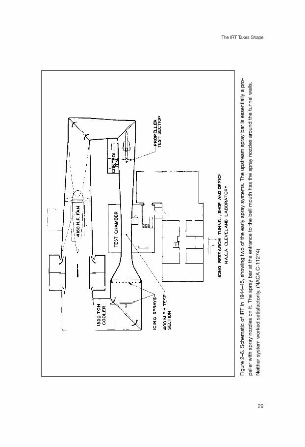
The IRT Takes Shape
29
Figu
re 2
–6.
Sch
emat
ic o
f IR
T in
194
4–45
, sh
owin
g tw
o of
the
ear
ly s
pra
y sy
stem
s. T
he u
pst
ream
sp
ray
bar
is e
ssen
tially
a p
ro-
pel
ler
with
sp
ray
nozz
les
on it
. Th
e sp
ray
bar
at
the
entr
ance
to
the
bel
l mou
th h
as t
he s
pra
y no
zzle
s ar
ound
the
tun
nel w
alls
.
Nei
ther
sys
tem
wor
ked
sat
isfa
ctor
ily.
(NA
CA
C-1
1274
)

and three modified scoops at flight angles of 0°, 4°, and 8°. There were two sets of tests,one for water ingestion and the other for icing.
During their 120 hours of testing, von Glahn and Renner discovered that theproblem with the C-46s was more one of water ingestion than ice. Scoops designedby Willson Hunter and Leo B. Kimball effectively prevented the entry of rain bymeans of inertia separation. Although these results came too late to be useful for theIndia-China air route, they provided the basis for the redesign of C-46s, and laterConvair 240s, that would be used after the war by the military services and commer-cial operators.
The icing tests of the C-46 scoops were less successful. As the researchers noted intheir report, “true cloud conditions were not simulated in the tunnel.” In most naturalimpact-icing conditions, they pointed out, the diameter of cloud droplets varied between10 and 30 microns, while the water content ranged between 0.5 and 1.5 grams per cubicmeter. The size of the drops in freezing mist and drizzle varied between 50 and 400microns, while freezing raindrops could attain a size of 2,000 microns. The spray systemin the IRT could produce droplets whose sizes were intermediate between an icing cloudand freezing rain. The NACA obviously had more work to do on the IRT’s spray system.18
Despite the problems with replicating a natural icing cloud, the IRT was kept busywith a variety of projects, most of which were generated by the military services. In1945, for example, the Air Material Command of the Army Air Forces asked the NACAto test a promising thermal-pneumatic wing de-icing system. The standard pneumaticboot system had several drawbacks. A certain amount of ice had to be tolerated in orderto permit cyclic removal. This inter-cycle ice created drag and was difficult to remove.The Air Material Command hoped that a thermal-pneumatic system would eliminatethe inter-cycle ice without requiring a large power supply.
The system tested in the IRT featured an electrically heated strip, 3 inches wide and33.5 inches long, that was cemented symmetrically about the leading chord line of theairfoil. Thirty-two inflatable tubes extended span-wise, sixteen on either side of the air-foil, adjacent to the electrically heated area. The tubes, made from neoprene-coveredstretchable nylon fabric, were 0.75 inches wide and extended rearward to approximately25 percent chord. They required an air pressure of 25 to 30 pounds for inflation.
Researchers William H. Gowan, Jr., and Donald R. Mulholland installed thesystem on a NACA 0018 airfoil, having a chord of 42 inches and a span of 36 inches.They mounted the airfoil from the ceiling of the test section, approximately 11 feetdownstream of a spray strut that atomized water to produce an icing cloud. The
“We Freeze to Please”
30
18 von Glahn and Renner, “Development of a Protected Air Scoop for the Reduction of Induction-System
Icing,” NACA TN 1134 (September 1946); interview with von Glahn by William M. Leary, 17 June 2000.

The IRT Takes Shape
31
Figure 2–7. Willson Hunter’s shirling spray arm, 9 July 1944. (NACA C-5312)
researchers first conducted aerodynamic tests on the model, with and without the de-icer installed, to obtain drag measurements. For the icing runs, they used angles ofattack of 0° and 4°, with airspeeds of 150 to 300 miles per hour and air temperaturesof 0°, 10°, and 20°F. The icing cloud contained an effective droplet size of approxi-mately 35 microns and a liquid water content of 2 grams per cubic meter. Ice coveredthe entire area of the de-icer system, Gowan and Mulholland noted, “and is consideredan extreme maximum icing condition, which probably would be experienced in theatmosphere only intermittently.” This condition, thus, could be considered “a severetest” of the de-icer.
The aerodynamic tests showed that when the de-icer was installed with no tubesinflated, drag increased 140 percent over a bare airfoil. This increased to a maximum of620 percent with tube inflation. The thermal-pneumatic system, however, when oper-ated on a 2-minute inflation cycle and with continuous electric heating of the leadingedge, prevented excessive ice formation. Small scattered residual ice remained after infla-tion, but was removed intermittently during later cycles. The system showed a good dealof promise and merited further development.19
Another major project in the tunnel involved experiments on two systems thatwere designed to prevent ice from forming on propellers. The slinger rings currentlyin use, which delivered de-icing fluid to the propellers by means of centrifugal force,worked under only limited conditions. The application of heat held out better possibilities.
Researchers Vernon E. Gray, Donald R. Mulholland, and Porter J. Perkins testedthree types of gas-heated hollow-steel propeller blades that had been mounted on a cut-off P-39 Bell Airacoba fuselage in the first diffuser section of the tunnel. To simulateicing, they used a ring of water spray with an average droplet size of 55 microns and anaverage liquid water content of 0.5 grams per cubic meter. Temperatures in the tunnelranged from -9° to 23°F. They found that a minimum heat input of 40,000 Btu perhour per blade would afford adequate ice protection.20
Researcher James P. Lewis used the same test apparatus to examine two electro-thermal systems for propeller ice protection. One method used external rubber-clad
“We Freeze to Please”
32
19 Gowan and Mulholland, “Effectiveness of Thermal-Pneumatic Airfoil Ice-Protection System,” NACA RM
E50K10a (1951). The authors noted that the research, which was done in 1945, was being published in 1951
“because of the inquiries that have been received regarding this type system.”20 NACA TN 1586 (May 1948), TN 1587 (May 1948), and TN 1588 (May 1948); Vernon H. Gray, “Propeller
Ice Protection by Means of Hot Gases in Hollow Blades,” NACA Conference on Aircraft Ice Prevention,
26–27 June 1947, pp. 119–27.

blade heaters with small chromel heating ribbons, while the other featured internalelectro-thermal heat. Tests in the IRT showed that both systems worked.21
On 23 January 1947, the focus of icing research shifted dramatically. Investigation ofpropellers came to an end. “Our experimental work on the simple air-heated blades,”Hunter noted, “has been completed to the point where reports can now be written on eachof the three-blade configurations.” Effective immediately, he informed his staff, the scheduleof the IRT would be changed to expedite research on jet engine inlet ice protection.22
Hunter was responding to the demands of the new jet age. As Arthur A. Brown ofPratt & Whitney stated, icing of turbine air induction systems posed “a very seriousproblem” for the industry. Engine manufacturers needed basic research on the inertialseparation of water and ice particles as a means to prevent icing. Some local surfaceheating may be necessary, but this would impose a large handicap on overall perform-ance. Experiments in Pratt & Whitney’s laminar flow wind tunnel had provedinconclusive because models had been tested at low airspeeds with only rough controlof droplet size. The results of an investigation by the NACA would be of “tremendousvalue in our efforts to design and build non-icing turbine power plant installations.”23
The NACA launched a three-phase investigation into the problem. It began withflight research. A Westinghouse 24C-2 turbojet engine with a ten-stage axial flow com-pressor was mounted below the wing of a B-24 bomber for tests in natural icingconditions. In March 1948, the B-24 spent one hour in an icing environment with theturbojet engine operating at a speed of 9,000 rpm. The liquid water of the icing cloud washighest during the first 15 minutes, reaching a peak of 0.38 grams per cubic meter. After45 minutes in the cloud, tail pipe temperature had increased from 761° to 1,065°, whilethrust had decreased from 1,234 to 910 pounds. The engine did not have to be shutdown, researcher Loren W. Acker noted, but a reduction in engine speed would have beenmandatory if it operated at a takeoff power of 12,000 rpm.
A second flight took place in April, this time with the turbojet engine operating at anormal cruising speed of 11,000 rpm. Again, the B-24 spent an hour in a natural icing envi-ronment. Upon entering the icing cloud, there was a sudden drop in engine thrust as icecollected on the cowl lip, disrupting airflow and destroying pressure recovery at the com-
The IRT Takes Shape
33
21 NACA TN 1520 (February 1948) and TN 1691 (August 1948); Lewis, “Electro-Thermal Methods of
Propeller Ice Protection. I - Cyclical De-Icing by External and Internal Blade Heaters,” NACA Conference on
Aircraft Ice Prevention, pp. 128–36.22 Hunter, “Revised Schedule for Icing Research Tunnel to Expedite Jet Engine Inlet Icing Research,”
23 January 1947, History Office, GRC.23 Brown, “Report of Pratt & Whitney Aircraft Subcommittee on Icing Problems,” 29 April 1948, NASA
History Office.

pressor inlet. After 18 minutes, however, a low liquid water content of 0.077 grams per cubicmeter and a high free air temperature of 25°F caused the inlet ice to melt and allowed theengine to return to normal operation. Seventeen minutes later, the liquid water content roserapidly to 0.49 grams. Fuel flow had to be increased to maintain engine speed, resulting in anincrease in tail pipe temperature and a rapid decrease in thrust from 1,950 to 1,700 pounds.After 45 minutes in the cloud, the engine was accelerated to the takeoff power of 12,000 rpmand held there for 2 minutes. At this point, the tail pipe temperature stabilized. “No generalconclusions may be drawn from these data,” Acker warned, “but no serious reduction inengine performance would be experienced in a icing condition similar to the one discussed.”24
In the next phase of the research program, William A. Fleming mounted theWestinghouse engine in a wing nacelle in the test section of the Altitude Wind Tunnel.The engine was equipped with an experimental ice protection system that bled hot gasfrom the turbine inlet and injected it into the air stream ahead of the compressor inlet,heating the air to above freezing. Tests were conducted at simulated altitudes of 5,000and 20,000 feet, with air temperatures that ranged from 0° to 35°F.
In an effort to simulate icing, Fleming placed a tower with five spray nozzles a distanceof 7 feet in front of the duct inlet. The nozzles, which had been designed by Hunter, injectedwater into a supersonic airstream through holes that were 0.010-inch in diameter. Hunteracknowledged that the spray system represented only “an intermediate makeshift design,”but he hoped to obtain droplets that were 10 to 15 microns in diameter. Unfortunately, hissystem failed to achieve this objective. While the water spray did not replicate natural icing,researcher Fleming reported, the system was adequate for his experiments.
Fleming found that ice formed so rapidly at the compressor inlet under severe icingconditions that the engine would flame out within 1 to 2 minutes. A hot-air bleedbacksystem could be used to prevent ice formation, but under severe conditions it wouldrequire that some 4 percent of the gas be bled to the engine inlet. This would reduce thrustby 18.8 percent (at 12,000 rpm) and increase fuel consumption by 16.5 percent.Obviously, additional research would be required to develop a less costly de-icing system.25
The third phase of the investigation was conducted in the IRT by researchers von Glahn,Edmund E. Callaghan, and Vernon H. Gray. The inlet guide vanes, previous studies hadrevealed, posed the greatest danger to the operation in icing conditions of an axial-flow tur-bojet engine. The researchers set out to test three systems that would protect the vulnerablevanes: surface heating, hot-gas bleedback, and inertia-separation inlets. Local heating could be
“We Freeze to Please”
34
24 Acker, “Natural Icing of an Axial-Flow Turbojet Engine in Flight for a Single Icing Condition,” NACA RM
E8F01a (1948).25 Fleming, “Hot-Gas Bleedback for Jet-Engine Ice Protection,” NACA Conference on Aircraft Ice Prevention,
pp. 86–92.

accomplished by passing heated gases through passages within the component walls, byinternal or external electrical heating pads, or by electrical eddy currents induced by a pul-sating magnetic field in the elements to be protected. The hot-gas bleedback system operatedby injecting hot gas into the air stream at the inlet, which protected the engine and most com-ponents in the inlet duct from icing. Finally, inertia separation of super-cooled water dropletsout of the engine inlet air stream would be accomplished by a special inlet and duct design.
Using scaled mockups of the engine inlet components, the researchers tested theeffectiveness of various ice-protection methods in simulated icing conditions with tem-peratures as low as -30°F and airspeeds up to 300 miles per hour. Measuring clouddroplet size and liquid water content in the tunnel by the rotating cylinder method, theywere satisfied that the simulated cloud was “in the range” of natural icing conditions.
The IRT Takes Shape
35
Figure 2–8. Aerial view of the Flight Propulsion Research Laboratory, Cleveland, Ohio, 1946.
(NACA C-15680)
Their investigation revealed that only the surface heating and hot-gas bleedback systemsafforded adequate ice protection. “Surface heating,” the researchers concluded, “either by gasheating or electrical means, appeared to be the most acceptable icing-protection method withregard to performance losses. Hot-gas bleedback, although causing undesirable thrust losses,offers an easy means of obtaining icing protection for some installations. The final choice ofan icing-protection system would depend upon the supply of heated gas and electrical poweravailable and on allowable performance and weight penalties associated with each system.”26
On 26 and 27 June 1947, AERL hosted its first conference on aircraft ice preven-tion. The meeting had been organized to convey the latest research results to individualsand organizations responsible for the design, development, and flight application of air-craft ice-protection equipment. It was an opportunity to showcase the work thatCleveland’s icing division had accomplished over the past three years.27
After reports by researchers at Ames on the progress of their work to develop a prac-tical thermal system, Hunter led off the AERL contingent with an optimistic summaryof Cleveland’s progress with induction system icing protection. It was not possible, heobserved, to design an efficient and ice-free system that would not require the pilot tocontrol heating nor apply alcohol for emergency de-icing.28 Fleming and von Glahn fol-lowed with progress reports on this work to protect jet inlets from icing. Gray and Lewisthen spoke about their propeller de-icing experiments. Finally, Callaghan reported onengine-cooling fan de-icing tests that had been conducted in the IRT.29
While the conference provided an excellent forum for discussion of the icingresearch that had been conducted at AERL over the past three years, all was not wellwith the Cleveland experimenters. Despite a substantial amount of effort and expense,the creation of a proper icing cloud in the IRT remained a vexing problem. AbeSilverstein, chief of the Wind Tunnels and Flight Division, was growing increasinglyimpatient with the situation. Never known for his even temper, Silverstein communi-cated his concern to Hunter in the clearest possible language.30
The problem faced by the icing division had been spelled out in April 1947 in a reportby professor H. G. Houghton of the NACA’s Subcommittee on De-Icing Problems. “Evenwith our incomplete knowledge of the properties of natural icing clouds,” Houghton had
“We Freeze to Please”
36
26 von Glahn, Callaghan, and Gray, “NACA Investigations of Icing-Protection Systems for Turbojet-Engine
Installations,” NACA RM E51B12 (1951).27 Wing Tips, 11 July 1947. Wing Tips was the house organ of the Lewis Research Center; copies are on file in
the History Office, GRC.28 Hunter, “Summary of Induction-System Ice-Protection Requirements for Reciprocating-Engine Power
Plants,” NACA Conference on Ice Prevention, pp. 71–85.29 NACA Conference on Aircraft Ice Prevention, pp. 86–112, 119–136.30 Interview with Vern G. Rollin by William M. Leary, 23 September 2000.
written, “it is obvious that present techniques for simulating icing conditions are entirelyinadequate.” Researchers needed suitable instruments for measuring the properties of theartificial cloud in the tunnel. Also, there had to be better control of drop-size distribution.The main problem was the production and distribution of a suitable spray. “I am forced toconclude,” Houghton had reported, “that it will not be possible to produce uniform icingconditions over more than a small fraction of cross-section of the measuring section of thepresent icing tunnel at AERL.”31
Despite Houghton’s pessimism, the next year, during which the name of theCleveland facility was changed to the Lewis Flight Propulsion Laboratory, saw substan-tial progress in developing a spray nozzle that would produce the needed droplet sizes.Given carte blanche by Silverstein to solve the problem, engineer Glen Hennings puttogether a team that modified the Hunter-designed nozzle that had been used earlier byFleming in the Altitude Wind Tunnel tests. Instead of a 0.010-inch diameter hole in thewater tube, Hennings substituted a 0.020-inch-diameter hypodermic tubing (internaldiameter about 0.010-inch) and soldered it into each nozzle. The resulting droplets couldthen be atomized by air flowing around the tubing, and much less compressed air wasrequired. In November 1948, Vern G. Rollin, Hunter’s deputy, reported, “water spraynozzles capable of producing narrow and wide ranges of droplet size and distributionfrom 5 to 200 microns have now been developed.”32
There still remained the problem of producing a uniform 4-foot by 4-foot icing cloud.Some 40 to 50 of the new nozzles were placed on six horizontal spray bars, and test runsbegan. Although the nozzles were built to the same specifications, they tended to act dif-ferently. In addition, some of the water tube holes would periodically plug up due to smallparticles in the water because the Cleveland water contained numerous minerals. EngineerChristenson solved this problem by purchasing a demineralizer and designing a system thatcould handle the demineralized water. Still, the air flow in the tunnel was not uniform. Asa result, calibration of the new spray system became a time-consuming, often frustratingprocess. “We worked for months,” researcher Thomas F. Gelder recalled, “experimentingwith different nozzle locations and with a range of air and water pressure levels.” By 1950,however, it had become possible to produce a uniform icing cloud in the tunnel. It hadtaken over five years, and it represented a significant technological achievement for theCleveland icing team. The way was now clear to accelerate research efforts in the IRT.33
The IRT Takes Shape
37
31 Houghton, “Progress Report for Meeting of Sub-Committee on De-Icing Problems,” 9 April 1947, NASA
History Office.32 Christenson interview; Rollin interview; Rollin, “Progress Report of Lewis Propulsion Research Laboratory,”
8 November 1948, NASA History Office.33 Christenson interview; interview with Thomas F. Gelder by William M. Leary, 18 June 2000.

39
Chapter 3
A Golden Age
While work on perfecting the spray system in the IRT was taking place,Cleveland’s role as the center for the NACA’s icing research was enhanced with thedecision to close the ice-prevention program at the Ames Research Center and transferflight research to AERL/Lewis. Ever since its opening in October 1940, Ames had ledthe way in developing a practical thermal de-icing system. Emphasizing flight research,the experimenters at Ames, under the driving leadership of Lewis Rodert, had flight-tested various thermal de- and anti-icing designs. The results had led to thedevelopment of a complete thermal system, covering the wings, tail surfaces, enginenacelles, windscreen, and other vulnerable parts of the airplane. In the spring of 1948,however, NACA Headquarters decided to consolidate icing research. As it was fareasier to move the aircraft than the IRT, the C-46 and B-24 that were being used forflight tests at Ames were transferred to Cleveland, together with meteorologist WilliamLewis of the Weather Bureau.1
The NACA’s flight research program never missed a beat with the move to theMidwest. One area of continuing interest concerned the physics of icing clouds.Researchers wanted to know how liquid water content and droplet size varied withtemperature, pressure, geographic location, synoptic conditions, and topography. Thework on this subject that was begun at Ames continued at Cleveland. Numerousflights were made over Lake Erie during which ice was collected on cylinders of dif-ferent diameters that rotated on a common axis and were exposed outside thethermal-protected C-46. The multicylinders were retracted after a flight through icingconditions, disassembled, and the ice was weighed. Comparing the weight of the icewith calculated values of collection efficiency (obtained theoretically) produced dataon liquid water content, average droplet size, and droplet-size distribution. Althoughthe data obtained from the rotating cylinder collection system was reliable, the
1 Bugos, “Rodert;” Sharp to NACA Headquarters, 25 May 1948, History Office, GRC.
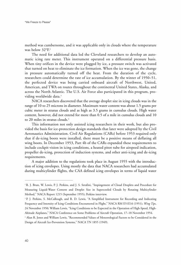
method was cumbersome, and it was applicable only in clouds where the temperaturewas below 32°F.2
The need for additional data led the Cleveland researchers to develop an auto-matic icing rate meter. This instrument operated on a differential pressure basis.When tiny orifices in the device were plugged by ice, a pressure switch was activatedthat turned on heat to eliminate the ice formation. When the ice was gone, the changein pressure automatically turned off the heat. From the duration of the cycle,researchers could determine the rate of ice accumulation. By the winter of 1950–51,the perfected device was being carried onboard aircraft of Northwest, United,American, and TWA on routes throughout the continental United States, Alaska, andacross the North Atlantic. The U.S. Air Force also participated in this program, pro-viding worldwide data.3
NACA researchers discovered that the average droplet size in icing clouds was in therange of 10 to 25 microns in diameter. Maximum water content was about 1.5 grams percubic meter in stratus clouds and as high as 3.5 grams in cumulus clouds. High watercontent, however, did not extend for more than 0.5 of a mile in cumulus clouds and 10to 20 miles in stratus clouds.4
This information not only assisted icing researchers in their work, but also pro-vided the basis for ice-protection design standards that later were adopted by the CivilAeronautics Administration. Civil Air Regulations (CARs) before 1953 required onlythat if de-icing boots were installed, there must be a positive means of deflating allwing boots. In December 1953, Part 4b of the CARs expanded these requirements toinclude cockpit vision in icing conditions, a heated pitot tube for airspeed indication,propeller de-icing, protection of induction systems, and other anti-icing and de-icingrequirements.
A major addition to the regulations took place in August 1955 with the introduc-tion of icing envelopes. Using mostly the data that NACA researchers had accumulatedduring multicylinder flights, the CAA defined icing envelopes in terms of liquid water
“We Freeze to Please”
40
2 R. J. Brun, W. Lewis, P. J. Perkins, and J. S. Serafini, “Impingement of Cloud Droplets and Procedure for
Measuring Liquid-Water Content and Droplet Size in Supercooled Clouds by Rotating Multicylinder
Method,” NACA Report 1215 (September 1955); Perkins interview.3 P. J. Perkins, S. McCullough, and R. D. Lewis, “A Simplified Instrument for Recording and Indicating
Frequency and Intensity of Icing Conditions Encountered in Flight,” NACA RM E51E16 (1951); Wing Tips,
24 November 1950; William Lewis, “Icing Conditions to be Expected in the Operation of High-Speed, High-
Altitude Airplanes,” NACA Conference on Some Problems of Aircraft Operation, 17–18 November 1954.4 Alun R. Jones and William Lewis, “Recommended Values of Meteorological Factors to be Considered in the
Design of Aircraft Ice-Prevention Systems,” NACA TN 1855 (1949).

content, mean effective diameter of droplets, temperature, and horizontal and verticalextent of the super-cooled icing cloud environment.5
When Part 4b was re-codified into Part 25 in February 1965, these icing envelopeswere incorporated into the new CAR as Appendix C. Part 25 provided that transport air-craft must be able to operate safely through forecasted continuous and intermittentmaximum icing conditions as determined by the icing envelopes in Appendix C. It fur-ther specified that the effectiveness of ice-protection systems had to be shown by flighttests in natural and simulated conditions and by icing tunnel tests.6
The flight research into thermal systems that had begun at Ames applied primarily toreciprocating-engine aircraft. Until 1950, with the exception of the research on jet engineinlet protection, work in the IRT also had been weighed heavily in the direction of piston-engine airplanes. But the NACA was well aware that the successful flight of the firstturbojet aircraft on 14 May 1941 had marked the beginning of a new era in the history
A Golden Age
41
Figure 3–1. Ice formed on the butterfly valves of an aircraft engine carburetor during tests in
the IRT, 28 July 1944. (NACA C-5690)
5 W. H. Weeks, CAA, to R. V. Rhode, NACA, 15 April 1954, NASA History Office, discussed the change in
regulations.6 D. T. Bowden, A. E. Gensemer, and C. A. Skeen, “Engineering Summary of Airframe Technical Icing Data,”
Technical Report ADS-4, Federal Aviation Agency Contract FA-WA-4250 (March 1964). ADS-4 was consid-
ered to be the “Icing Bible” until the appearance of the Aircraft Icing Handbook in 1991.

of aviation. Thin-winged interceptor aircraft, the NACA concluded, with their high ratesof climb and descent and high cruising altitudes, might not require airframe icing protec-tion. Jet transports, on the other hand, would need such protection during climb anddescent. Both interceptors and transports had to have complete engine protection.7
By the early 1950s, Cleveland’s focus had shifted to jet aircraft icing protection.Tunnel usage shot up dramatically, as researchers sought solutions to the icing problemsof high-altitude, high-speed aircraft. At the beginning of the decade, researchers workedin the IRT about 500 hours a year. In 1951, however, usage increased to 651 hours. TheIRT operated for 917 hours in 1953, 871 hours in 1954, and 817 hours in 1955. Peak
“We Freeze to Please”
42
Figure 3–2. Propellor with internal heaters after icing run, 15 September 1944. (NACA C-6599)
7 von Glahn, “Some Considerations of the Need for Icing Protection of High-Speed High-Altitude Airplanes,”
NACA Conference on Some Problems of Aircraft Operation.

staffing of the facility came in June 1954 with thirteen professionals, six other personnel,and twelve supporting personnel.8
Management of the branch also changed, as von Glahn replaced Hunter, who becamechief of research at Lewis.9 Born in Germany in 1919, von Glahn’s family had moved to the
A Golden Age
43
Figure 3–3. James P. Lewis inspects fuselage of a P-39 mounted in IRT for study of ice forma-
tion on propellors. (NACA C-10186)
8 C. S. Moore, “Research Facilities Operation Summary, 1944–1955,” n.d., History Office, GRC.9 The circumstances and exact date of Hunter’s departure are uncertain, although the change in leadership
appeared to take place in late 1950 or early 1951. In the early 1960s, Hunter became director of conferences
in NASA’s Public Affairs Office in Washington, DC. In 1966, he was appointed NASA’s senior scientific rep-
resentative to Australia. He retired in 1979 and died in 1983. The information on his career is taken from the
obituary clipping in the NASA History Office.

United States in 1926 due to the instability of the Weimar Republic. Von Glahn was raisedin Pennsylvania, New Jersey, and New York. In 1942, he graduated from RensselaerPolytechnic Institute with a degree in aeronautical engineering. He remained at RPI until1944 as an instructor in the aeronautics department, teaching and doing wind tunnelresearch. Gordon Campbell of BFGoodrich, who also was an RPI alumnus, told von Glahnabout a position in icing research that was opening at the new NACA laboratory in Cleveland.Von Glahn was hired by NACA just prior to the beginnings of IRT operations.10
In designing ice-protection systems for large jet transports, manufacturers firstneeded information on what happened when super-cooled water droplets struck an air-
“We Freeze to Please”
44
Figure 3–4. Gerald H. H. Arnold views an icing experiment during a visit to AERL, 9 November
1944. Dr. George Lewis is on the far left; Willson Hunter is between Arnold; and the Colonel is
on the right. (NACA C-7491)
10 von Glahn interview.
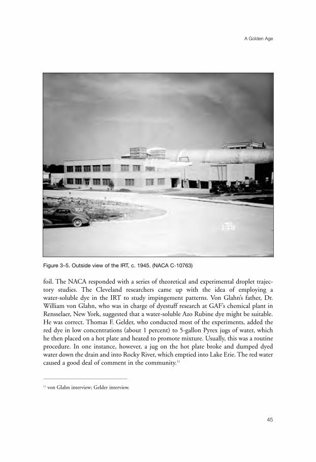
foil. The NACA responded with a series of theoretical and experimental droplet trajec-tory studies. The Cleveland researchers came up with the idea of employing awater-soluble dye in the IRT to study impingement patterns. Von Glahn’s father, Dr.William von Glahn, who was in charge of dyestuff research at GAF’s chemical plant inRensselaer, New York, suggested that a water-soluble Azo Rubine dye might be suitable.He was correct. Thomas F. Gelder, who conducted most of the experiments, added thered dye in low concentrations (about 1 percent) to 5-gallon Pyrex jugs of water, whichhe then placed on a hot plate and heated to promote mixture. Usually, this was a routineprocedure. In one instance, however, a jug on the hot plate broke and dumped dyedwater down the drain and into Rocky River, which emptied into Lake Erie. The red watercaused a good deal of comment in the community.11
A Golden Age
45
Figure 3–5. Outside view of the IRT, c. 1945. (NACA C-10763)
11 von Glahn interview; Gelder interview.

“We Freeze to Please”
46
Figure 3–6. Rig for testing propellor ice-protection systems, 1946. (NACA C-15254)

The dyed water was placed in 20-gallon tanks, which were connected to six spraynozzles in the IRT. Gelder then taped blotting paper to the airfoil that was to be tested.After the tunnel was operating, a 5- to 10-second spray of water was released into theairstream. The blotter strip was then removed, and a special punch was used to cut outrectangular strips, 0.125 of an inch wide by 1.5 inches long. Each strip was placed in anumbered test tube on a long rack, and distilled water was added. A light beam passingthrough the mixture would determine the dye concentration in the water.12
The dye impingement research involved a good deal of tedious work for theresearchers, and, later, the women who usually did the required hand calculations werebrought in to handle the task. Jane Gavlak recalls that Gelder’s strips had to be placed inboiling water to remove the dye. She then had to match the resultant dye against a com-parison chart to determine concentration. Although the work was hard on both eyes andhands, the results were worth the effort. For the first time, the researchers could deter-mine where the droplets were striking and in what concentration. Thus, the principalproblem areas that needed icing protection could be identified.13
Although the trajectory studies provided information on the rate that ice wouldaccumulate on an airfoil, NACA researchers still needed reliable data on the shape of theice formations. Initially, flight tests had been made to measure the aerodynamic penaltiescaused by various ice shapes. Researchers found that rime icing, primarily associated withlow temperatures, had a streamlined shape and did not greatly affect performance.However, heavy glaze icing, associated with high water content and temperatures nearfreezing, was a different story. Glaze ice formations protruded into the airstream andcaused significant aerodynamic penalties.14
The controlled conditions of the IRT allowed researchers to test airfoils of differentsizes, thicknesses, and shapes over a wide range of angles of attack and icing conditions.Work done in the early 1950s by von Glahn and Vernon Gray produced drag curves forNACA 63A-009 (6.9-foot chord, 36-inch sweep) and NACA 65-212 (8-foot chord) air-
A Golden Age
47
12 Gelder interview; Gelder, W. H. Smyers, and von Glahn, “Experimental Droplet Impingement on Several
Two-Dimensional Airfoils with Thickness Ratios of 6 to 16 Percent,” NACA TN 3839 (1956).13 von Glahn, Gelder, and W. H. Smyers, “A Dye-Tracer Technique for Experimentally Obtaining Impingement
Characteristics of Arbitrary Bodies and Method for Determining Droplet Size Distribution,” NACA TN 3338
(1955); Leary interview with Jane Gavlak Zager, 27 June 2001.14 For an excellent summary of the NACA’s icing research during this period, see von Glahn, “The Icing
Problem - Current Status of NACA Techniques and Research,” originally presented at the Ottawa AGARD
Conference, 10–17 June 1955, and reproduced in “Select Bibliography of NACA-NASA Aircraft Icing
Publications,” NASA TM 81651 (1981), pp. 1–10, together with microfiche copies of all important technical
papers.

“We Freeze to Please”
48
Figu
re 3
–7.
Icin
g R
esea
rch
Tunn
el in
vest
igat
ion
of t
he e
ffect
iven
ess
of v
ario
us p
rop
ello
r an
ti-ic
ing
dev
ices
, 19
46.
(NA
CA
C-1
5557
)

foils under a variety of icing conditions. For example, at high angles of attack (8 °), iceformations on the upper surface near the leading edge of the NACA 65-212 airfoilcaused large increases in drag and incipient stalling.15
The data points for these—and all other—experiments were obtained with the assis-tance of a corps of young women who were known as “computers.” During experiments,researchers would take about 100 data points during an evening’s test run. A bank ofsome 100 manometer tubes, 0.75 of an inch apart and with a 0.1-inch scale between thetwo tubes, recorded pressure, strain gauge readings, and other information. Cameraswould take photographs of the manometers at different stages of the experiment. Thenext day, a stack of these photographs would appear in the NACA’s computing section,located on the second floor of the 8 x 6-foot tunnel building. There were three offices inthe section: a “big office” which contained some thirty-five young women; a middleoffice, with twenty to twenty-five women; and a small office, with ten women withadvanced mathematical skills. Jane Gavlak, who worked in the “big office” between 1948and 1954, was one of the “computers” who would read and plot the measurements fromthe tubes. Reading and plotting one manometer board of 100 tubes would yield 1 datapoint. As the experiments would take 100 data points in an evening, the researcherswould not get the readings for two or three weeks.
It took “hours and hours” of tedious work to read and plot the results, Gavlakremembered. Nonetheless, it was a good job for a high school graduate. It paid well($1,900 a year for a 40-hour week), and there was little turnover in the section. Womenusually left only for marriage and pregnancy. Morale was high, as researchers often wouldinvolve the women in their work. An experienced “computer” could often identify prob-lems with the data and alert researchers that there might have been a mistake in takingthe information. Such an alert could save weeks of efforts for a researcher.16
During the 1940s, NACA research had established the feasibility and design basisfor a thermal anti-icing system that continuously applied sufficient heat to critical air-craft components to maintain impinging super-cooled droplets in a liquid state over theentire surface. This was the research, based on studies of propeller-driven aircraft, thathad won Rodert the Collier Trophy for 1946. In 1950, however, Gelder and Lewis pre-sented a paper at a meeting of the Institute of Aeronautical Sciences (the predecessor ofthe American Institute of Aeronautics and Astronautics) that called into question the via-
A Golden Age
49
15 von Glahn and Gray, “Effect of Ice Formations on Section Drag of Swept NACA 63A-009 Airfoil with Partial
Span Leading Edge Slat for Various Modes of Thermal Ice Protection,” NACA RM E53J30 (1954); Gray and
von Glahn, “Effect of Ice and Frost Formations on Drag of NACA 65-212 Airfoil for Various Modes of
Thermal Ice Protection,” NACA TN 2962 (1953).16 Jane Gavlak Zager interview.

bility of a continuous heat system for large high-speed, high-altitude jet aircraft. Heatingrequirements for jet transports, they found, could be enormous—up to 7,500,000 Btuper hour under certain conditions, or 10 percent bleed of the engine airflow.Performance penalties and excessive fuel consumption of this magnitude could precludethe use of continuous heating on jet aircraft.17
The alternative to continuous heating would be cyclic de-icing. In a cyclic system,ice would be allowed to accrete on an airfoil for a short period of time. A short butintense application of heat would then be applied to melt the bond of ice to the surfaceof the airfoil and allow it to be removed by aerodynamic forces. The heat would be ter-
“We Freeze to Please”
50
Figure 3–8. First icing conference at Lewis, 26 June 1947. (NACA C-19051)
17 The 1950 paper evolved into Gelder, Lewis, and Stanley L. Koutz, “Icing Protection for a Turbojet Transport
Airplane: Heating Requirements, Methods of Protection, and Performance Penalties,” NACA TN 2866
(1953).

minated and the surface allowed to cool and re-ice before another application of heatwould be necessary. Although cyclic de-icing previously had been studied for propellersand jet engine guide vanes, the results of these investigations did not apply to the airfoilsthat were found on the wings and empennages of jet aircraft. In order to obtain infor-mation on cyclic de-icing systems that could be used by jet transports, the NACAlaunched a major investigation of the various types of heaters and methods of heating inthe early 1950s.
The investigation began with an examination of the characteristics and require-ments of de-icing a NACA 62 (2)-216 airfoil by using an external electric heater.Researchers Lewis and Bowden mounted the airfoil, which had an 8-foot chord and a6-foot span, vertically in the test section of the IRT. Technicians installed an externalelectric heater on the forward section of the model, extending chordwise a distance of14.1 percent chord on the upper surface and 23.4 percent cord on the lower surface.The heater consisted of 0.125-inch-wide Nichrome resistance strips, each 0.001-inchthick and spaced 0.0313 of an inch apart. The heating ribbons, enclosed between twolayers of neoprene, were connected to a variable cycle timer that allowed researchers tocontrol the heat-on and heat-off periods. A recording wattmeter measured total powerinput to each heater element.
The airfoil also featured a parting strip to facilitate ice removal. The parting stripconsisted of a 1-inch-wide spanwise area located near the airfoil stagnation region thatwas continuously heated. During icing tests, researchers found that quick and completeice removal, when cyclic heat was applied to the airfoil, could only be achieved with theassistance of the parting strip.
In conducting the icing tests, Lewis and Bowden used a variety of air temperatures,airspeeds, angles of attack, droplet sizes, and liquid water content. Their aim was todetermine the minimum power output that was required for complete and consistent iceremoval. They found that the most important variables in determining power require-ments were temperature and heat-on time. Heat-off time, droplet size, and liquid watercontent had only a secondary effect, while angle of attack had no appreciable effect. Highlocal application of power and short—less than 15 seconds—heating periods providedthe most efficient removal of ice, with a maximum total energy output of only 490,000Btu per hour.18
While an electric de-icing system accomplished the task of removing ice with lowenergy outputs, it had numerous disadvantages. It added to the weight of the aircraft, wassusceptible to failure by damage to the heating circuits, was costly to maintain, and posed
A Golden Age
51
18 Lewis and Bowden, “Preliminary Investigation of Cyclic De-Icing of an Airfoil Using an External Electric
Heater,” NACA RM E51J30 (1952).

“We Freeze to Please”
52
Figure 3–9. Water spray test in the IRT, 22 September 1947. (NACA C-19747)
a potential fire hazard if the system failed because of heater burnout. The alternative wasa hot-gas system. If the large heating requirements associated with continuous hot-gasheating could be reduced by a cyclical system, ice could be removed without an increasein aircraft weight. A hot-gas cyclical system also had the advantages of integral designwith the aircraft structure, low maintenance costs, and no fire hazards.
For tests of the hot-gas cyclical de-icing system, researchers Gray, Bowden, and vonGlahn used a NACA 65(1)-212 airfoil of 8-foot chord. The leading edge of the airfoilwas heated by gas flow through chordwise passages in a double-skin construction similarto that found in a continuous gas-heating system. The airfoil also incorporated theparting strip that had been employed in the electric de-icing system experiments.
The researchers subjected the model to a wide range of conditions. They used air-speeds of 180 and 280 miles per hour, angles of attack from 2° to 8°, air temperatures of-11° to 20°F, and liquid water content of 0.3 to 1.2 grams per cubic meter. To melt theice, they employed high-pressure heated air, regulating the temperature by adding coldair, and controlling the pressure by means of a pressure-regulating valve. Gas temperatureat the inlet of the supply duct ranged from 200° to 510°F.
Their investigation revealed that the ice could be removed satisfactorily withcycle ratios (total cycle time divided by heat-on periods) of 10 to 26. “For minimumrunback, efficient ice removal, and minimum total heat input,” they concluded,“short heat-on periods of about 15 seconds with heat-off periods of 260 seconds gavethe best results.” Savings in heat over continuous anti-icing system requirements wereconsiderable.19
The final phase of the investigation involved a comparative study of several methodsof cyclic gas-heating systems. Researchers Gray and Bowden again used as their model aNACA 65(1)-212 airfoil with a 6-foot span, 8-foot chord, and a maximum thickness of11.5 inches. They tested three systems that differed mainly in the way that they obtainedelevated gas temperatures at the leading edge and in their use of parting strips. Onesystem used a double-duct return-flow gas supply arrangement with spanwise and chord-wise parting strips. A second system was similar to the first one but without the partingstrips. The third system featured a single-duct non-return gas supply arrangement and noparting strips.
The first system gave the best results. Gray and Bowden found that 50 percentlonger heat-on periods were required for systems without parting strips. They also dis-covered that the single-passage gas-supply duct system needed an 85 percent longerheat-on period than did the dual-duct systems. Overall, heat source requirements for
A Golden Age
53
19 Gray, Bowden, and von Glahn, “Preliminary Results of Cyclical De-Icing of a Gas-Heated Airfoil,” NACA
RM E51J29 (1952).
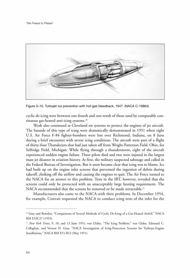
cyclic de-icing were between one-fourth and one-tenth of those used by comparable con-tinuous gas-heated anti-icing systems.20
Work also continued at Cleveland on systems to protect the engines of jet aircraft.The hazards of this type of icing were dramatically demonstrated in 1951 when eightU.S. Air Force F-84 fighter-bombers were lost over Richmond, Indiana, on 8 Juneduring a brief encounter with severe icing conditions. The aircraft were part of a flightof thirty-four Thunderjets that had just taken off from Wright-Patterson Field, Ohio, forSelfridge Field, Michigan. While flying through a thunderstorm, eight of the aircraftexperienced sudden engine failure. Three pilots died and two were injured in the largestmass jet disaster in aviation history. At first, the military suspected sabotage and called inthe Federal Bureau of Investigation. But it soon became clear that icing was to blame. Icehad built up on the engine inlet screens that prevented the ingestion of debris duringtakeoff, choking off the airflow and causing the engines to quit. The Air Force turned tothe NACA for an answer to this problem. Tests in the IRT, however, revealed that thescreens could only be protected with an unacceptably large heating requirement. TheNACA recommended that the screens be removed or be made retractable.21
Manufacturers also came to the NACA with their problems. In December 1954,for example, Convair requested the NACA to conduct icing tests of the inlet for the
“We Freeze to Please”
54
Figure 3–10. Turbojet ice prevention with hot-gas bleedback, 1947. (NACA C-19864)
20 Gray and Bowden, “Comparisons of Several Methods of Cyclic De-Icing of a Gas-Heated Airfoil,” NACA
RM E53C27 (1953).21 New York Times, 9, 10, and 13 June 1951; von Glahn, “The Icing Problem;” von Glahn, Edmund C.
Callaghan, and Vernon H. Gray, “NACA Investigation of Icing-Protection Systems for Turbojet-Engine
Installations,” NACA RM E51-B12 (May 1951).

General Electric J-79-GE-1 turbojet engine that would power their advanced super-sonic B-58 Hustler. The stainless-steel cowl of the engine was heated by internalelectric heating elements manufactured by BFGoodrich, while a gas-heat system thatwas designed and manufactured by Convair protected the center body and supportstruts. The NACA’s plan called for researchers to secure aerodynamic and dropletimpingement data, which would be followed by tests of the ice-prevention systems forinlet components.
Convair provided two inlet models for tests in the IRT—one unheated and oneheated. The unheated model arrived in April 1955. The research scheduled called for twelveaerodynamic runs, followed by nine dye runs, with an average time of 6 hours per run.Icing studies with the heated model would take place from mid-June to mid-July.
While the dry air aerodynamic and droplet impingement studies were satisfactorilyconcluded, problems showed up during the icing runs. The gas-heated center body andsupport structure performed well in the icing tests, but the electrically heated cowlproved unsatisfactory. Researchers found that the cowl lip could not be protected com-pletely at air temperatures below 25°F because the heater installation left a cold area atthe cowl leading edge. As an alternative to the electric-heat system, the NACA suggestedthat Convair adopt a gas-heated cowl.22
In addition to airframes and engines, radome ice protection also attracted the atten-tion of NACA researchers. By the early 1950s, radar had become an importantcomponent of commercial transports and all-weather military aircraft. U.S. Air Forceinterceptors employed radar not only for weather information, but also for targettracking and fire control. In order to evaluate the icing and icing protection of radomes,two Northrop F-89 Scorpion domes were tested in the IRT. The APG-33 radar of the F-89C was housed in a narrow, parabolic dome with a nose radius of 6.955 inches, whilethe larger APG-40 radar used by F-89Ds occupied a blunt, hemispherical dome that hada nose radius of 13.91 inches. Both radomes (0.375-inch thick) were constructed ofmolded fiberglass that had been impregnated with synthetic resin and coated with arubber-like material to resist erosion and abrasion.
Researchers James P. Lewis and Robert J. Blade began their three-phase investiga-tion by determining the rate and location of water-droplet impingement, and themanner in which the radome accreted ice. Using a dye-tracing technique, they wrappedstrips of absorbent paper around the radome surface, which they then exposed to awater-dye spray solution for 1–10 seconds. A spectrophotometer determined the quan-tity of dye collected in the strips. As they knew the dye concentration in the spray cloud,
A Golden Age
55
22 Silverstein to Convair, 7 January 1955, and 2 April 1955; von Glahn to Silverstein, 22 August 1955; all in
History Office, GRC.
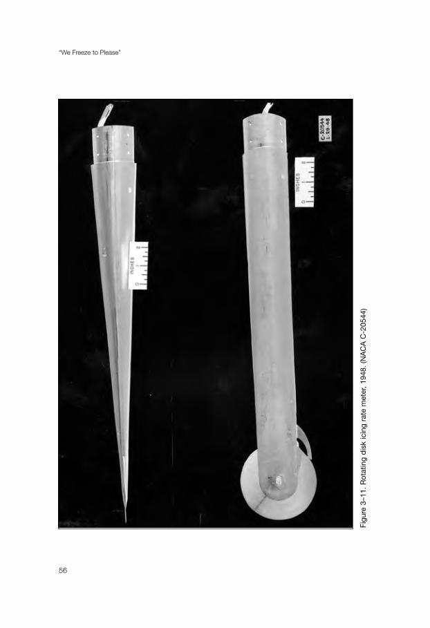
“We Freeze to Please”
56
Figu
re 3
–11.
Rot
atin
g d
isk
icin
g ra
te m
eter
, 19
48.
(NA
CA
C-2
0544
)

they could establish the local rate of deposition of water on the radome and the localcollection efficiency.
After acquiring the impingement information, Lewis and Blade next subjected theradomes for 15 minutes to an icing cloud with air temperatures of -5° to 12°F, a liquidwater content of 0.9 grams per cubic meter, and droplet diameters of 10 to 12 microns.They conducted the tests at airspeeds of 168 and 275 miles per hour and with angles ofattack of 0° and 4°. At the end of the exposure period, they took photographs of the iceformations and measured the ice thickness.
The second phase of the program involved tests of the interference to the radar sig-nals that were caused by icing. Lewis and Blade first tuned the radar system for 100percent transmission, and then they checked the values against previously obtained meas-urements in dry-air static tests. After icing the radome for 15 minutes, the researchersagain measured transmissions at various scan angles.
In the final phase of the radome experiments, Lewis and Blade assessed the effec-tiveness of the F-89’s fluid-protection system. The system consisted of a spray nozzlelocated in the radome nose that sprayed a mixture of ethylene glycol and water ahead ofthe radome. The mixture was swept back on the radome surface by the airstream toremove or prevent icing. The researchers tested several types of air-atomizing and fluid-atomizing nozzles in various spray locations.
The radome investigation determined that the extent of impingement covered mostof the radome area scanned by the radar beam in normal operations. Ice formations weretypical for similar shapes, while the icing rate varied from 1.25 to 3 inches per hourunder test conditions. Radome icing, they found, had a serious effect on the operationof the radar, with significant losses in transmission with ice formations as small as 0.125-inch thick and for an icing period of less than 5 minutes. Provided that a deflecting typeof air-atomizing nozzle was used, the fluid-protection system would afford satisfactoryde-icing of the radomes with flow rates of less than 4 gallons an hour and for de-icingperiods of less than 5 minutes.
As little had been known previously about radome icing, especially the effect of icingon radar transmissions, the NACA study made an especially significant contribution toan area of growing interest by both military and commercial operators.23
High-speed, high-altitude jet interceptors generally operated at altitudes of about20,000 feet, where icing encounters were rare. The aircraft, however, were exposed toicing during the climb and descent phases of flight. In order to obtain data on the fre-quency and severity of these icing encounters, the NACA and the U.S. Air Force
A Golden Age
57
23 Lewis and Blade, “Experimental Investigation of Radome Icing and Icing Protection,” NACA RM E52J31
(1953).
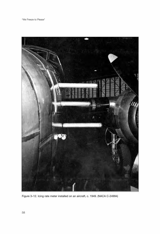
“We Freeze to Please”
58
Figure 3–12. Icing rate meter installed on an aircraft, c. 1949. (NACA C-24994)
conducted a one-year program during which interceptors were equipped with pressure-type icing rate meters. Five Air Defense Command F-89s at Duluth, Minnesota, wherepolar air masses predominated, would carry NACA-designed icing rate meters,mounted near the nose and 7 inches out from the fuselage, from August 1955 to June1956. Another five F-89s, flying from Seattle, Washington, would sample icing condi-tions in the maritime air masses of the Pacific Northwest from November 1955 toSeptember 1956.
Researcher Porter Perkins, who analyzed the data, found that the F-89s encoun-tered icing fifty-nine times in 1,178 flights in both areas. In Duluth, 70 percent of theseicing incidents took place below 10,000 feet, while in Seattle, 75 percent occurredbelow 15,000 feet. Ice thickness on the small sensing probe averaged less than 0.0313of an inch and did not exceed 0.5 of an inch during steep angles of flight for shortperiods through generally thin cloud layers. Although Perkins cautioned that the lim-ited information from the surveyed areas could be used only as “a very rough estimateof the probabilities of occurrence for icing for other locations and periods,” the studydid add to the growing body of data that suggested that icing protection equipmentmight not be necessary for interceptors.24
While interceptors could expect only brief exposures to icing, little information wasavailable on the performance penalty that even small amounts of ice might exact. TheNACA’s research on the aerodynamic effects of icing had been conducted on airfoil sec-tions that were used by large transports and bombers. The high-speed, high-altitudeinterceptors, however, featured a thin airfoil with a thickness ratio of the order of 4 per-cent. Clearly, a study of this type of airfoil would be necessary in order for manufacturersand operators to assess the need for icing protection equipment on lifting and controlsurfaces for high-speed interceptors.
Researchers Gray and von Glahn set out to investigate this problem, using as theirmodel a NACA 65A004 airfoil section of 6-foot chord. They equipped the stainless steelmodel with a 42-inch-span removable wooden leading-edge section, extending to 27 per-cent of the chord, that would enable researchers to install a variety of ice-protectionsystems. They attached the airfoil section to a balance frame in the test section. Theframe was connected to a six-component force-balance system. Lift, drag, and pitchingmoment would be recorded simultaneously on tape by an electrically controlled printingmechanism at each balance scale.
The researchers tested the airfoil at airspeeds of 109 and 240 miles per hour, air tem-peratures of 0°, 10°, and 25°F, and angles of attack of 0° to 12°. The model was allowed
A Golden Age
59
24 Perkins, “Icing Frequencies Experienced During Climb and Descent by Fighter-Interceptor Aircraft,” NACA
TN 4314 (1958).
to collect ice for a period of 3 to 17 minutes, while data was recorded at intervals of 0.5–2minutes. Gray and von Glahn used an icing spray with a liquid water content of 0.45 to2.0 grams per cubic meter, as measured with a pressure-type icing rate meter. Droplet sizeranged from 11 to 19 microns. The researchers could adjust droplet size by changing thespray nozzle pressure settings. These settings had been determined from a previous cali-bration of droplet size obtained from tests with water droplets that carried a dye solution.At the end of the icing period, the researchers took photographs to record the shape andsize of the ice formations.
Following the lift, drag, and pitching moment studies, technicians removed thetrailing edge of the airfoil at the 82 percent chord and modified it to incorporate a simplehinged flap. Researchers then conducted additional icing tests with angles of attack from3.3° to 8.8° and flap angles up to +/- 15°. Ice formations on the leading edge, theyobserved, produced no significant changes on the control-surface hinge movements.
An analysis of the aerodynamic data and ice formation photographs showed that themagnitude of aerodynamic penalties was primarily a function of the shape and size of theice formations near the leading edge of the airfoil. And the shape and size of these ice for-mations, Gray and von Glahn noted, were functions “of such variables as water content,droplet size, air temperature, icing time, airfoil angle of attack, and airspeed.” Theresearchers drew no conclusion from the data about the need of interceptor aircraft foricing protection systems. Rather, the purpose of the investigation was to provide the AirForce and manufacturers with a sufficient body of data that would enable them to reacha decision on the matter.25
Addressing a conference in Ottawa in June 1955, branch chief von Glahn pro-claimed: “Aircraft are now capable of flying in icing clouds without difficulty . . . becauseresearch by the NACA and others has provided the engineering basis for ice-protectionsystems.” Ironically, the very success of the NACA’s icing research led administrators toquestion the need to continue the program. If, as von Glahn had indicated, the majorproblems that remained were engineering in nature, there seemed little need for funda-mental research. And the NACA’s mission was to do research on the cutting edge oftechnology; engineering was best left to manufacturers.26
Abe Silverstein, now chief of research at Lewis, concluded in the mid-1950s thatthe NACA’s icing research program should be terminated. He believed the icing staffcould be better employed elsewhere, as the agency’s mission came to emphasize thespace program. Although von Glahn and other members of his staff believed that fur-ther work remained to be done, they could not quarrel with the basic premise that their
“We Freeze to Please”
60
25 Gray and von Glahn, “Aerodynamic Effects Caused by Icing of an Unswept NACA 65A004 Airfoil,” NACA
TN 4155 (1958).26 von Glahn, “The Icing Problem.”
fundamental research had succeeded. In any event, Silverstein had made up his mind.At one point, the chief of research offered a heroic solution to terminate work in theIRT when he suggested that a bomb be placed under the tunnel. Although a joke, thecomment nonetheless clearly conveyed Silverstein’s position on the future of icingresearch at Lewis.27
The IRT’s level of activity decreased in 1956 to 555 hours. The next year, usageplummeted to 257 hours. By the end of 1957, all of the NACA’s research activity in theIRT had ended, and the icing section’s talented staff were transferred to other dutieswithin the renamed (in 1958) National Aeronautics and Space Administration (NASA).Icing research had come to an end—or so it seemed.28
A Golden Age
61
27 von Glahn interview.28 C. S. Moore, “Major Test Facilities, 1955–1962,” n.d., History Office, GRC.

63
Chapter 4
Industry in the IRT
The IRT, despite NASA’s decision to terminate research programs that used thefacility, remained attractive to industry as the largest refrigerated icing tunnel in theworld. In January and February 1958, Convair tested the wing and tail of its new 880 jettransport in the IRT. Later in the year, Grumman came to the facility to examine waysto protect the large radome of its W2F (Hawkeye) Airborne Early Warning aircraftagainst icing. Total tunnel usage, however, amounted only to 150 hours in 1958. Activityincreased slightly in 1959 with the tunnel running for 200 hours, most of this time beingspent on tests of slotted wings for the Douglas DC-8. There were no tests at all in theIRT for the first eleven months of 1960, and only 45 hours of running time inDecember. As industry seemed finished with the tunnel, NASA placed the IRT instandby status and considered deactivating the facility. Indeed, the IRT might well havebeen torn down had it not been for the interest of a young engineer from the VertolDivision of the Boeing Company.1
In March 1960, the helicopter division of Boeing asked for a volunteer to test the engineinlet of the CH-47 Chinook in the natural icing facility atop Mount Washington. Althoughhe had no experience with icing, Andrew A. Peterson of Vertol’s Internal AerodynamicsGroup decided that the assignment might be an interesting adventure. After two weeks oftests on the windy 6,250-foot mountain, it was clear that more work was necessary on asystem to redistribute engine bleed air to prevent icing. As the Air Force was in charge of theChinook project, he sought advice from the technical staff at Wright-Patterson Air Force Base.The Air Force recommended that he use the IRT for further tests. Peterson, who had neverheard of the facility, was given Uwe von Glahn’s name as a contact at Lewis.2
1 “Models and Run Days for Major Facilities: Icing Research Tunnel, 1950–1986,” n.d.; Ronald J. Blaha,
“Completed Schedules of NASA-Lewis Wind Tunnels, Facilities and Aircraft, 1944 to 1990,” February 1991;
both documents are in the History Office, GRC.2 Interview with Andrew A. Peterson by William M. Leary, 22 October 2000.

Von Glahn, Peterson discovered, was not enthusiastic about the prospect ofreopening the tunnel. The IRT, he said, would soon be torn down. Peterson, however,managed to convince him that helicopter icing needs were unique. Flight tests were pro-hibitively expensive and dangerous. A good deal of valuable work could beaccomplished in the icing tunnel. Von Glahn told Peterson that he would take thematter up with his superiors.
NASA finally agreed to allow Peterson to run tests in the IRT. The Boeing researcherthen obtained Air Force sponsorship, which meant that no extra money would berequired to use the government facility. Peterson went to Cleveland at the beginning ofJune 1961. When NASA’s technicians turned on the tunnel, all the circuit breakers blew.It took three days to check the electrical circuits and get the tunnel running.
Tests of the engine inlet began on 5 June and lasted until 23 June 1966. As a resultof this work, Boeing was able to qualify the Chinook’s bleed-air anti-icing system.Pleased with the usefulness of the facility, Peterson returned in August for two monthsof work that resulted in certification by the FAA of the electro-thermal and bleed-air
“We Freeze to Please”
64
Figure 4–1. B-24 with Westinghouse 24C-2 turbojet engine mounted under wing, 1948.
(NACA C-20866)

anti-icing systems of the V-107, a turbine-powered machine that was destined for com-mercial service with New York Airways.3
Peterson used the IRT frequently over the next four years. When he wanted toarrange tests, he would call Lewis and ask for a meeting to review the proposed test plan.He then would draft a letter for a government agency to send to NASA for sponsorship.After contacting Vernon Gray at Lewis, he would set up a schedule for the tests in thetunnel. Initially, NASA conducted the experiments. After the first few tests, however,Boeing’s staff ran the tests, while Lewis technical personnel operated the IRT.
Between 1962 and 1964, Peterson conducted tests to qualify the electro-thermalanti-icing system for the engine inlet of the CH-46 (Sea Knight) and CH-113, bothderivatives of the V-107. While he was by far the leading user of the facility, he was not
Industry in the IRT
65
Figure 4–2. Westinghouse 24C-2 turbojet engine under wing of B-24, 1949. (NACA C-23705)
3 Peterson, “Component Icing Tests Conducted at the NASA Lewis (Glenn) Research Center, Icing Research
Tunnel,” 2 August 2000. Copy provided to the author by Mr. Peterson.

“We Freeze to Please”
66
Figure 4–3. Ice formed on spray nozzles during test, 2 September 1949. (NACA C-23984)

the only one. In 1964, Aerocommander and Learjet tested engine inlets in the tunnel.Indeed, by the mid-1960s, the IRT had become a favorite testing site not only for heli-copters, but also for general aviation and large transports. Douglas tested the wing oftheir DC-9 in the tunnel. Other experiments involved the engine inlet of the DC-10, theradome of the Lockheed C5A, the wing of the Gulfstream G1159, the Beech King Airengine inlet, and the refueling probe of a Sikorsky helicopter.4
As part of the FAA certification program for the icing protection system for theslotted wing of the L-1011, Lockheed used the tunnel for a major series of the tests thatran from 5 November through 30 December 1968. A full-scale model of an L-1011 wingsection (near the tip) was put through a series of icing conditions to simulate cruise,high-speed hold, descent, and low-speed hold. In all, ninety-five tests were conducted todemonstrate the ability of the system to deliver bleed air to the four outboard leading-edge slats of the L-1011 wing and satisfy FAA certification requirements.5
Heavy tunnel usage by industry continued into the 1970s, with Piper, GE, Douglas,Sikorsky, Deutsche Airbus, LTV, Boeing, Learjet, Teledyne, and other companies testingtheir products under icing conditions. By 1978, companies were competing for tunneltime. That year saw the IRT in operation for 750 hours during 124 days.6
It was clear by the late 1970s that icing remained a major concern for aviation. Whenthe Society of Automotive Engineers (SAE) met in Dallas in October 1972, the individualsin the organization who focused on aeronautics decided to set up a panel to investigate iceaccretion prediction methods and to identify deficiencies in the current technology.Chaired by Vinod K. Rajpaul of Boeing, the panel reported in May 1978 that little signif-icant work on icing had been done since the NACA research of the 1950s. It concludedthat there was an urgent need for a new icing research program to deal with aircraft tech-nology that had changed significantly over the past 20 years. Commercial transportmanufacturers were especially interested in developing more fuel-efficient systems in lightof rising fuel prices due to the actions of the oil-producing nations (OPEC).7
In addition to commercial aviation, the U.S. Army was growing concerned abouticing problems. In the late 1960s, as the war in Vietnam wound down, Army aviationhad begun to focus on operational difficulties in Europe. One of the major problems wasthe inability of helicopters and some fixed-wing aircraft to operate in icy conditions. In
Industry in the IRT
67
4 Blaha, “Completed Schedules.”5 Lockheed-California Company, “Full Scale Wing Slat Model Anti-Icing Test Program Conducted in NASA
6’ x 9’ Icing Tunnel,” n.d. [1970]; copy in the History Office, GRC.6 Blaha, “Completed Schedules;” “Models and Run Days.”7 Rajpaul, “Aircraft Icing Research Panel Report to SAE AC-9 Committee,” May 1978; copy in NASA
Conference Publication 2086 (1978), pp. 129–31.

1970, Richard I. Adams, as lead engineer for environmental technology, became respon-sible for aircraft icing research and development programs at the U.S. Army’s AppliedTechnology Laboratory in Fort Eustis, Virginia.8
Adams launched an R & D program to establish meteorological criteria for helicopterice-protection systems. The major technological shortcoming, he early determined, was rotorblade protection. A UH-1H (Huey) was modified to act as a test bed, incorporating experi-mental ice-protection systems. Initially, the redesigned UH-1N flight-tested a cyclicelectro-thermal de-icing concept that the Army had developed. Results proved disappointing,primarily due to excessive weight requirements for the system. “There is a pressing need,” heconcluded, “to develop advanced concepts for rotor blade ice protection to provide militaryand civil operators a cost-effective, light-weight means of protecting rotor blades.”9
“We Freeze to Please”
68
Figure 4–4. Unprotected propeller spinning after icing run, 1948. (NACA C-34635)
8 Adams to Leary, 9 November 2000.9 Adams, “Overview of Helicopter Ice Protection System Development,” NASA Conference Report 2086, pp.
39–65; Adams to Leary, 19 June 2001.
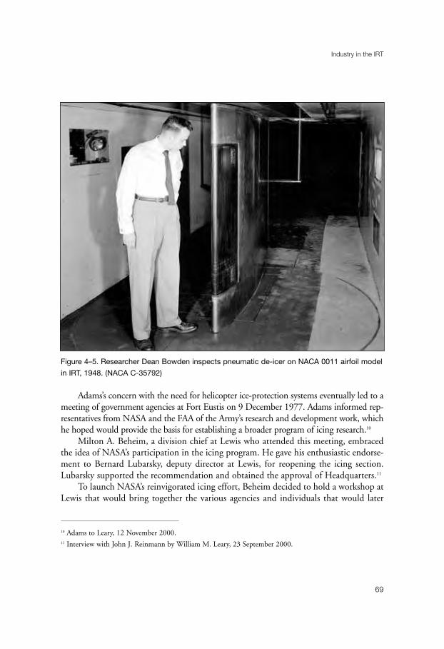
Adams’s concern with the need for helicopter ice-protection systems eventually led to ameeting of government agencies at Fort Eustis on 9 December 1977. Adams informed rep-resentatives from NASA and the FAA of the Army’s research and development work, whichhe hoped would provide the basis for establishing a broader program of icing research.10
Milton A. Beheim, a division chief at Lewis who attended this meeting, embracedthe idea of NASA’s participation in the icing program. He gave his enthusiastic endorse-ment to Bernard Lubarsky, deputy director at Lewis, for reopening the icing section.Lubarsky supported the recommendation and obtained the approval of Headquarters.11
To launch NASA’s reinvigorated icing effort, Beheim decided to hold a workshop atLewis that would bring together the various agencies and individuals that would later
Industry in the IRT
69
Figure 4–5. Researcher Dean Bowden inspects pneumatic de-icer on NACA 0011 airfoil model
in IRT, 1948. (NACA C-35792)
10 Adams to Leary, 12 November 2000.11 Interview with John J. Reinmann by William M. Leary, 23 September 2000.
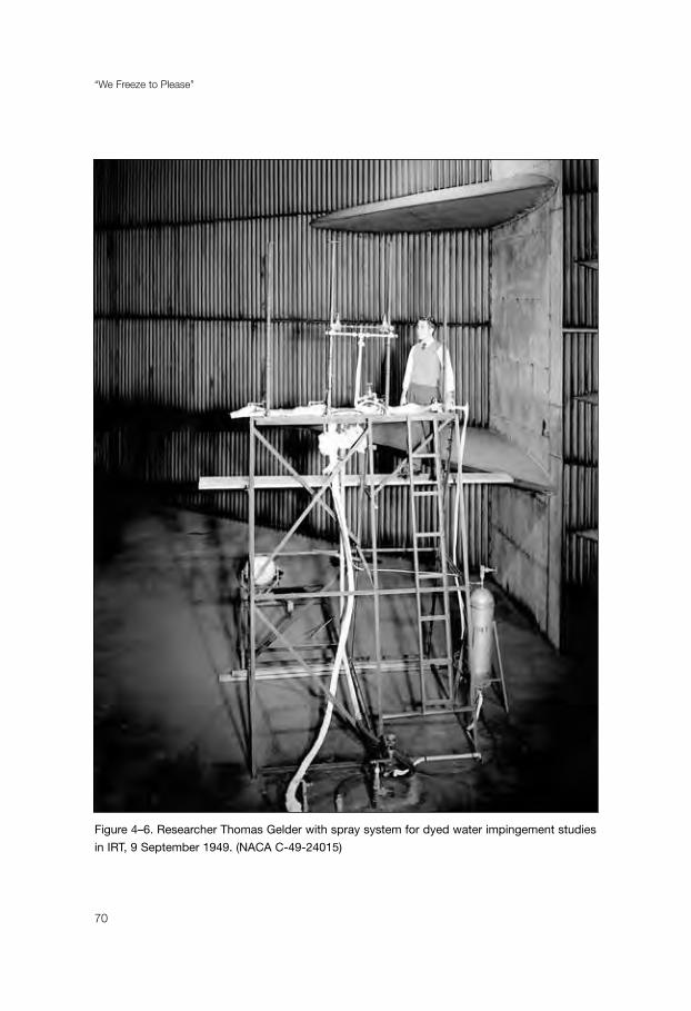
“We Freeze to Please”
70
Figure 4–6. Researcher Thomas Gelder with spray system for dyed water impingement studies
in IRT, 9 September 1949. (NACA C-49-24015)

constitute the “in flight icing community.” Sponsored jointly with the FAA, and withplanning assistance from the Department of Defense, the workshop met on 19–21 July1978. Participation exceeded all expectations. In all, 113 individuals from industry, themilitary, and government agencies attended, including representatives from theNetherlands, United Kingdom, France, Sweden, and Norway.
Had this meeting been held a few years earlier, Lubarsky observed in his welcomingremarks, “I believe we could have all sat around a card table.” But this had changed.Requests for testing in the IRT had reached a point where they were difficult to satisfy. Thisrenewed interest in icing, Lubarsky said, was being driven by new requirements and by theopportunities offered by new technologies. Commercial transport manufacturers wantedmore efficient equipment. General aviation interests wanted to certify their aircraft to flyinto forecast icing conditions. There was a similar need for helicopters, stemming from mil-itary requirements to operate throughout Europe during the winter, and from commercialneeds to service oil rigs in the North Sea and off the Alaskan coast.12
John H. Enders, from the Safety Office in NASA Headquarters, then made theintroduction. The intent of the workshop, he noted, was to share information from awide range of specialist groups, most of whom normally have little or no regular contactwith one another. The participants in the workshop then toured the IRT and theAltitude Wind Tunnel. Enders told them that NASA was considering a proposal tomodify the AWT into a large subsonic propulsion and icing test facility.13
Conference participants were then assigned to committees on meteorologicalresearch, icing forecasting, systems development, civil operations, military operations,and icing research and facilities. Over the next day and a half, the committees consid-ered all aspects of their area of responsibility, and then they rendered a final report ofrecommendations.
Beheim delivered the executive summary of the workshop. He began by reviewingthe past, and then he looked to future developments in icing research. Between 1940 and1955, he said, industry and government laboratories, especially the NACA, had made asignificant effort to define the natural icing environment, determine its effect on aircraftcomponents, and design technologies for ice protection. The results of this work estab-lished the basis for certification requirements for large transports. This effort had endedin the late 1950s, as transports shifted to jet power and had ample supplies of engine-bled air to cope with icing during ascents and descents.
Although it is clear that the old NACA research was held in high regard, Beheim con-tinued, the lack of serious efforts to advance the state of the art since 1957 had resulted in
Industry in the IRT
71
12 Lubarsky, “Welcoming Remarks,” NASA Conference Publication 2086, pp. iii–iv.13 Enders, “Introduction,” ibid., pp. vii–ix.
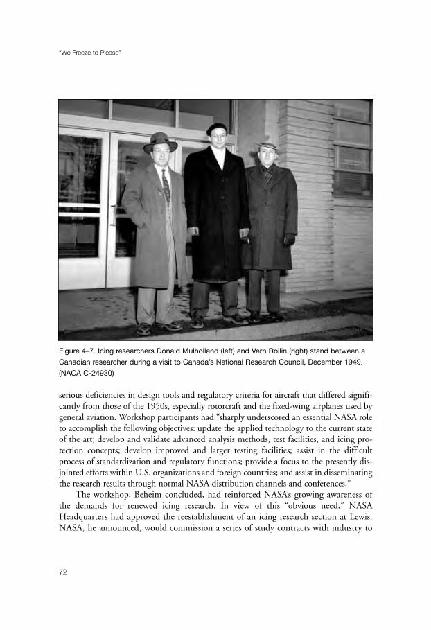
serious deficiencies in design tools and regulatory criteria for aircraft that differed signifi-cantly from those of the 1950s, especially rotorcraft and the fixed-wing airplanes used bygeneral aviation. Workshop participants had “sharply underscored an essential NASA roleto accomplish the following objectives: update the applied technology to the current stateof the art; develop and validate advanced analysis methods, test facilities, and icing pro-tection concepts; develop improved and larger testing facilities; assist in the difficultprocess of standardization and regulatory functions; provide a focus to the presently dis-jointed efforts within U.S. organizations and foreign countries; and assist in disseminatingthe research results through normal NASA distribution channels and conferences.”
The workshop, Beheim concluded, had reinforced NASA’s growing awareness ofthe demands for renewed icing research. In view of this “obvious need,” NASAHeadquarters had approved the reestablishment of an icing research section at Lewis.NASA, he announced, would commission a series of study contracts with industry to
“We Freeze to Please”
72
Figure 4–7. Icing researchers Donald Mulholland (left) and Vern Rollin (right) stand between a
Canadian researcher during a visit to Canada’s National Research Council, December 1949.
(NACA C-24930)

define the program for a larger research effort in the future. Also, plans to modernizethe IRT had been initiated. Finally, feasibility studies were underway for the design ofa much larger icing tunnel with higher speeds and variable altitude capability; although,the eventual outcome of these studies to convert the AWT “will be highly dependent onbudgetary restraints.”14
To manage the IRT, Beheim selected Harold Zager. Already a section head inBeheim’s Wind Tunnel and Flight Division, Zager’s responsibilities included the 8’ x 6’,9’ x 15’, and 10’ x 10’ wind tunnels. But he had never before seen an icing tunnel. Hisfirst look at the facility was not encouraging. The IRT had been used rarely and was notbeing maintained. Fred Murray, an experienced mechanic, had been looking after thetunnel, but he had lacked the authority to get much done. The ceiling had rotted andhad fallen down on the air exchange doors, which could not be moved. Zager toldBeheim that he was not prepared to take responsibility for the IRT until repairs had beenmade so that it could be safely operated. It was “a good time” to make such a request,Zager recalled, and Beheim agreed to the necessary expenditures.15
Beheim, with the assistance of branch chief Roger Luidens, also recruited the firstfour researchers to staff the tunnel. To form the core group of researchers, Beheim usedhis power of “persuasion” on William A. Olsen, Jr., a talented experimentalist; BernardJ. Blaha, an accomplished wind tunnel research engineer; Peggy Evanich, an experiencedaeronautical engineer who had worked for Lockheed before joining NASA; and RobertJ. Shaw. Shaw’s experience was more-or-less typical of what happened. Shaw recalls thatBeheim called him into the office shortly before the workshop concluded and asked himto become part of the icing research group that was being formed. There was no moneyat present, Beheim allowed, and the decision had been made to start out as a sectionrather than at the higher level of branch. (The section would become a branch in 1987.)Shaw, who was working on V-STOL inlets, was not exactly excited at the prospect of atransfer. Icing was not in the mainstream at Lewis. During the 1970s, however, one didnot turn down “requests” by management. “You did what you were told,” Shaw com-mented. As it turned out, the transfer to icing research became “one of the best breaks ofmy career.” It was “a fascinating experience,” he recalled in 2001, and “the most fabulousten years of my thirty-one-year career with NASA.”16
Beheim still had to find someone to head the section. Advertisements for the positionproduced a number of applicants. In the end, he opted for John J. Reinmann. This wouldprove a happy choice. After graduating from Case Institute with a B.S. (1954) and M.S.
Industry in the IRT
73
14 Beheim, “Executive Summary of Aircraft Icing Specialists Workshop,” ibid., pp. 1–12.15 Leary interview with Zager, 27 June 2001.16 Leary interview with Robert J. Shaw, 26 June 2001.

(1957) in mechanical engineering, Reinmann went on to receive an M.S. in physics fromJohn Carroll University. He then took a position with the New Devices Laboratory of TRW,Inc., attaining the position of project engineer while working on the development of Rankinepower conversion systems for space satellites. Reinmann joined NASA in 1961 and spent“seventeen glorious years” doing research into plasma physics and thermonuclear fusion forspace propulsion, with fifteen of those years serving as head of the High Temperature PlasmaSection. In 1978, however, the Lewis laboratory experienced the worst reduction in force inthe history of the facility. Bruce T. Lundin, director of Lewis, announced that he was notinterested in any research that did not pay off in five years. As a result, Reinmann and otherresearchers in his section were soon out of a job—and without “bumping” rights.
NASA offered Reinmann only one option: to join a new computational fluidmechanics training program. Although this would mean a reduction in salary, the needto support a large family left Reinmann with no choice but to accept. On a more posi-tive note, he looked forward to acquiring expertise in the field of computational fluid
“We Freeze to Please”
74
Figure 4–8. Carrier components and condensors of the refrigeration plant, 5 February 1950.
(NACA C-25219)

mechanics. Just as he completed the nine-month program, Reinmann saw the announce-ment for a section head of icing research. “After looking into it a bit further,” he recalled,“I became excited about it. First, it was a field in which I felt very comfortable: thermo-dynamics, fluid mechanics, and heat transfer. It was like coming home. Second, it hadthe Icing Research Tunnel, which meant I could bring analysis and experiments alongtogether. Third, I felt that with my previous analytical and experimental research experi-ence, and with my newly acquired capabilities in computational fluid mechanics, I waseminently qualified.” Finally, the position would mean a return to his previous pay gradeas section head. “I had nine children to feed, clothe, and send to college,” he pointed out.“So, believe me, I didn’t take this lightly.”17
Part of the Low-Speed Aerodynamics Branch (Luidens) of the Wind Tunnel andFlight Division (Beheim), the new section’s first task was to write the specifications for
Industry in the IRT
75
Figure 4–9. Refrigeration plant for the IRT and AWT, 1 March 1951. (NACA C-27262)
17 Reinmann interview; Reinmann to Leary, 1 April 2001.
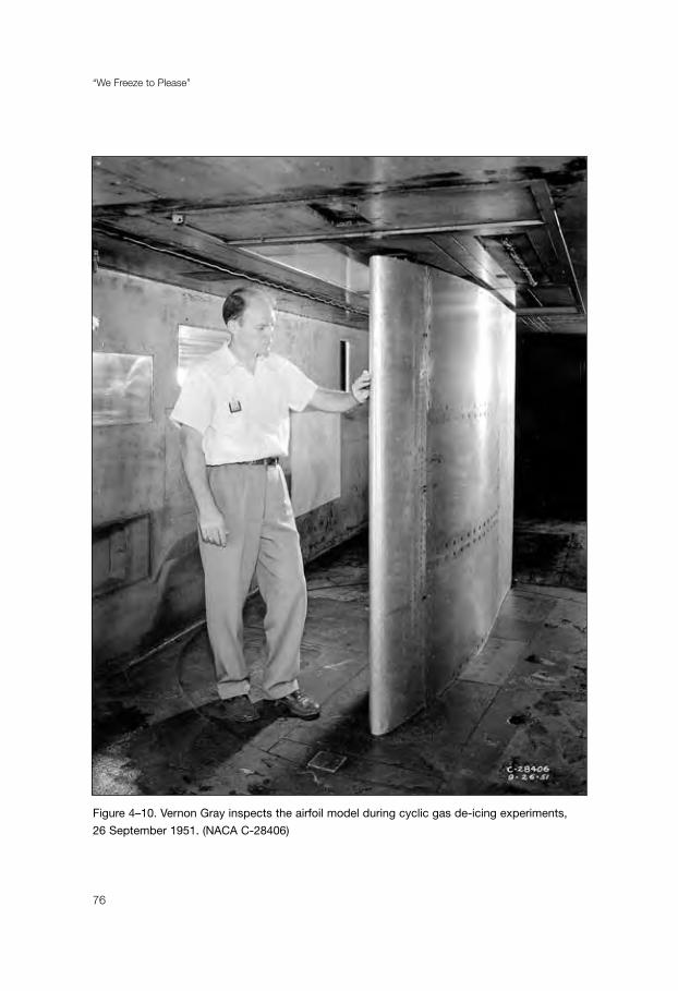
“We Freeze to Please”
76
Figure 4–10. Vernon Gray inspects the airfoil model during cyclic gas de-icing experiments,
26 September 1951. (NACA C-28406)

the three study contracts that Beheim wanted to commission. Larry P. Koegeboehn ofthe Douglas Aircraft Company was selected to write the report on the icing researchrequirements of commercial aviation. B. K. Breeze and G. M. Clark of RockwellInternational would survey the light transport and general aviation icing researchrequirement. Finally, Peterson, Leo Dadone, and David Bevan of Boeing Vertol wouldhandle rotorcraft icing needs.18
Breeze and Clark were the first to finish. General aviation and light transport air-craft, they pointed out in their report, had a higher exposure to icing conditions thanlarge transports. Furthermore, they paid greater penalties for ice-protection systems dueto their smaller dimensions. A major effort was needed to resolve the icing problem withthe aid of new technologies. “It becomes increasingly apparent that in order to obtain thewind tunnel database required to solve general aviation aircraft problems,” the authorscontinued, “the NASA icing wind tunnels will have to be used to a greater degree, andimprovements will have to be made to expand the applicability of these tunnels, increasethe accuracy of test measurements, and reduce the turnaround time between tests.”
Breeze and Clark recommended that the IRT be improved with modern recordingand data-processing equipment, and that the AWT be converted into an icing tunnel.The report went on to list thirty-three areas of desired research. Although there was noindustry consensus on research priorities, there was general agreement that a training filmfor flight in icing conditions would be beneficial. Finally, there was a consensus thatNASA Lewis should be “the center of aircraft icing expertise for basic research and con-sultation, and should act as a clearing house for exchange of information for industryinvolvement.”19
Koegeboehn next weighed in with the views of the commercial aircraft industry. Heagreed with the previous report’s recommendation that the IRT be modernized with anautomated control system and that the AWT be converted into an icing tunnel. Notingthat rising fuel prices in recent years had encouraged aircraft designers to seek ice-protection systems that would save weight and fuel, he proposed, in order of priority,four research goals that should be reached within four years. First, NASA should developand test an electro-impulse de-icing system that would save fuel and be low in cost.Second, super-critical airfoils should undergo ice accretion tests in the IRT, with meas-urement of drag and lift coefficients. Third, NASA should test various devices to measurecloud properties and recommend acceptable types to the military and FAA. Finally, anew computer program for ice-protection analysis should be developed.
Industry in the IRT
77
18 Reinmann interview.19 Breeze and Clark, “Light Transport and General Aviation Aircraft Icing Research Requirements,” NACA
Contractor Report (CR) 165290 (March 1981).
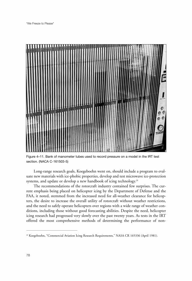
Long-range research goals, Koegeboehn went on, should include a program to eval-uate new materials with ice-phobic properties, develop and test microwave ice-protectionsystems, and update or develop a new handbook of icing technology.20
The recommendations of the rotorcraft industry contained few surprises. The cur-rent emphasis being placed on helicopter icing by the Department of Defense and theFAA, it noted, stemmed from the increased need for all-weather clearance for helicop-ters, the desire to increase the overall utility of rotorcraft without weather restrictions,and the need to safely operate helicopters over regions with a wide range of weather con-ditions, including those without good forecasting abilities. Despite the need, helicoptericing research had progressed very slowly over the past twenty years. As tests in the IRToffered the most comprehensive methods of determining the performance of non-
“We Freeze to Please”
78
Figure 4–11. Bank of manometer tubes used to record pressure on a model in the IRT test
section. (NACA C-161503-5)
20 Koegeboehn, “Commercial Aviation Icing Research Requirements,” NASA CR 165336 (April 1981).

rotating ice-protection systems under varied conditions, the report recommended thatthe “upgrading of existing major icing test facilities must continue as rapidly as fundspermit.” The IRT could be modernized to improve the range of liquid water content anddroplet size to meet civil and military helicopter requirements. Also, the AWT should bereactivated as an icing tunnel.
The report emphasized that the helicopter rotor was the “key area” requiring amajor effort. Although the IRT was not large enough to accommodate a full-scalerotating main rotor, work was already underway to test an OH-58 tail rotor rig in thetunnel. These tests offered the opportunity to determine the feasibility of using scale-model rotors for testing.21
Reinmann was pleased with the three studies, which generated tremendous interestboth at Lewis and at NASA Headquarters. They not only enabled NASA to put togethera responsive program with well-defined objectives, but they also made everyone awarethat NASA “was back in the icing business.” The main problem with implementing theprogram, however, was lack of funds.22
For the first three years, Reinmann had to work with a limited annual budget of only$500,000. But the situation improved in 1981, thanks largely to the interest of Allen R.(“Dick”) Tobiason. Trained as an engineering test pilot and a retired Master ArmyAviator, Tobiason became the manager of aviation safety technology at NASAHeadquarters in 1980. “I found many low-funded programs,” he recalled, “that did notappear to have the potential for improving safety in the short term, nor were thereprospects to increase total funding.” He decided to cancel several of the smaller programsand use the money to increase funding for programs which had more immediateprospects for improving safety and which used unique NASA facilities. One of the majorrecipients of Tobiason’s largess was icing research.23
Tobiason not only quadrupled icing funding, but he also arranged for the transferto Lewis of a Twin Otter research aircraft. “I wanted,” he noted, “some test airplanesinvolved to prove theory, wind tunnel results, and analytical models.” The Langley lab-oratory, where the Twin Otter was based, was reluctant to part with the airplane.Tobiason, however, had the necessary “clout” to override Langley’s objections. Thetransfer included an agreement between Lewis and Langley to share data.
Finally, Tobiason wanted closer relations between Lewis and the FAA, which wasin the process of revising icing standards for certification. Largely through his
Industry in the IRT
79
21 Peterson, Dadone, and Bevan, “Rotorcraft Aviation Icing Research Requirements,” NASA CR 165344
(May 1981).22 Reinmann interview.23 Lewis News, 10 April 1981; Tobiason to Leary, 10 July 2001.

efforts, a cooperative agreement was signed, resulting in the transfer of funds fromthe FAA to Lewis and the assignment of an FAA staff representative to the Clevelandlaboratory.
Tobiason’s efforts were certainly appreciated by Reinmann. One of the fewpeople at Headquarters to “put his money where his mouth was,” Tobiason repre-sented “a breath of fresh air” for icing researchers. And his emphasis on safety issuesproved fortuitous, as a dramatic accident would soon focus national attention onicing problems.24
“We Freeze to Please”
80
24 Reinmann to Leary, 11 July 2001.

81
Chapter 5
Back in Business
On the morning of 13 January 1982, Washington, DC, was in the midst of a majorsnowstorm that would dump 6 inches on the nation’s capital. Schools and businessesclosed; Congress recessed early; and National Airport was shut down. By noon, as thesteady snowfall gave way to scattered showers, the airport reopened. Just before 1:40 P.M.,however, it closed again to allow plows to clear the instrument runway (18/36). It wasscheduled to resume operations at 2:30 P.M.
As the plows did their work, passengers boarded Air Florida flight 90, a Boeing 737-222B, that was bound for sunny Ft. Lauderdale. Captain Larry Wheaton asked forde-icing as the seventy-four passengers, no doubt happy at the prospect of escaping thenorthern winter, found their seats. The de-icing was started, but then it stopped afterWheaton was informed that there would be a further delay, and that he would beeleventh in line for departure. At 3:00 P.M., the airplane was de-iced for 10 minutes.Thirteen minutes after that, Wheaton was cleared to push back from the gate. The tug,however, its tires spinning in the snow, could not move the Boeing 737. Wheaton sug-gested that he use the aircraft’s thrust reversers to gain some momentum. Althoughengaged for about 1.5 minutes, the reversers succeeded only in throwing up slush andsnow. The aircraft remained immobile. Finally, a second tug, equipped with chains on itstires, managed to push back the 737.
Palm 90, the aircraft’s call sign, then taxied out behind a New York Air DC-9 andbecame number seventeen in line for takeoff. A light snow continued to fall as Palm 90waited to depart on runway 36. Finally, at 3:59 P.M., the control tower gave Wheatonclearance to take the runway. Visibility at this time was down to 0.25 of a mile.
Seconds later, the tower gave Palm 90 permission to depart. As the aircraft reachedrotation speed, the nose of the 737 pitched up sharply. “Forward, forward, easy,”Wheaton told copilot Roger Pettit. But the aircraft did not respond. “Come on.Forward, forward,” Wheaton exclaimed. “Larry, we’re going down,” copilot Pettitresponded. “I know it,” were Wheaton’s last words, just before Palm 90 slammed intothe 14th Street Bridge.

The Boeing 737 crushed four automobiles on the busy bridge, killing five people.The airplane then hit the ice-covered Potomac River, sinking up to its tail. Seventy pas-sengers and four crewmembers died in the crash. Only one flight attendant and fourpassengers were pulled from the wreckage in a dramatic rescue that received full televi-sion coverage.
The National Transportation Safety Board listed a number of causes for the acci-dent, but assigned major responsibility to icing. The NTSB report faulted the flight crewfor failing to turn on engine anti-ice during ground operations and takeoff, their deci-sion to take off with snow and ice on the airfoil surfaces of the 737, and the prolongedground delay between de-icing and receipt of takeoff clearance, during which the aircraftwas exposed to constant precipitation.1
This tragic and dramatic accident, which received the widest possible media cov-erage, thrust the dangers of icing to the forefront of national attention. It certainly hada major impact on NASA’s icing research program. Reinmann, who had been hardpressed to show icing as an important safety issue, now had a vivid example of the needfor additional research for safety purposes. It became easier for him to argue for funds forthe icing section. Eventually, the impact of the Air Florida accident eased the way forReinmann to obtain approval for a major renovation of the IRT.2
Even before the Air Florida accident, Reinmann had begun research programs thatresponded to the needs of industry for better methods of ice protection. For a time, itappeared that the answer to the vexing problem of helicopter rotor blade de-icing mightwell lie in an improved version of the Goodrich de-icer boot. One of the oldest ice-protection methods, the pneumatic boot was attractive as a low-weight, low-cost, andlow-power method of ice removal. It had been studied by Lockheed Aircraft under anArmy contract during the 1970s. The concept had been rejected, however, because theneoprene rubber of the boot could not withstand heavy rain and could be damaged orcompletely torn off by centrifugal force.3
Goodrich investigated a variety of materials to improve the durability of theboots. The company finally became convinced that polyurethane (trade name,Estane) would solve the problems that had been associated with neoprene. In 1979,Goodrich and NASA conducted a joint program to test the polyurethane boot in theIRT. Placing a 6-foot segment of a full-scale Bell UH-1H (Huey) rotor blade in the
“We Freeze to Please”
82
1 National Transportation Safety Board Report NTSB-AAR-82-8, 10 August 1981.2 Reinmann interview.3 Robert J. Shaw, John J. Reinmann, and Thomas L. Miller, “NASA’s Rotorcraft Icing Research Program,”
preprint for the NASA/Army Rotorcraft Technology Conference, NASA Ames Research Center, 17–19 March
1987; copy in the History Office, GRC.
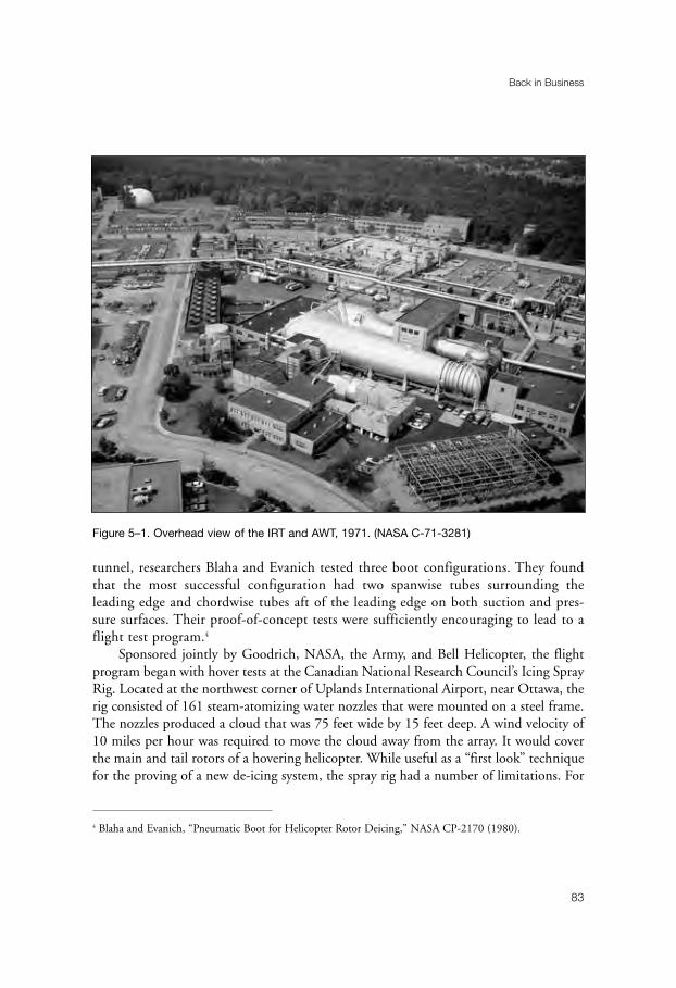
tunnel, researchers Blaha and Evanich tested three boot configurations. They foundthat the most successful configuration had two spanwise tubes surrounding theleading edge and chordwise tubes aft of the leading edge on both suction and pres-sure surfaces. Their proof-of-concept tests were sufficiently encouraging to lead to aflight test program.4
Sponsored jointly by Goodrich, NASA, the Army, and Bell Helicopter, the flightprogram began with hover tests at the Canadian National Research Council’s Icing SprayRig. Located at the northwest corner of Uplands International Airport, near Ottawa, therig consisted of 161 steam-atomizing water nozzles that were mounted on a steel frame.The nozzles produced a cloud that was 75 feet wide by 15 feet deep. A wind velocity of10 miles per hour was required to move the cloud away from the array. It would coverthe main and tail rotors of a hovering helicopter. While useful as a “first look” techniquefor the proving of a new de-icing system, the spray rig had a number of limitations. For
Back in Business
83
Figure 5–1. Overhead view of the IRT and AWT, 1971. (NASA C-71-3281)
4 Blaha and Evanich, “Pneumatic Boot for Helicopter Rotor Deicing,” NASA CP-2170 (1980).
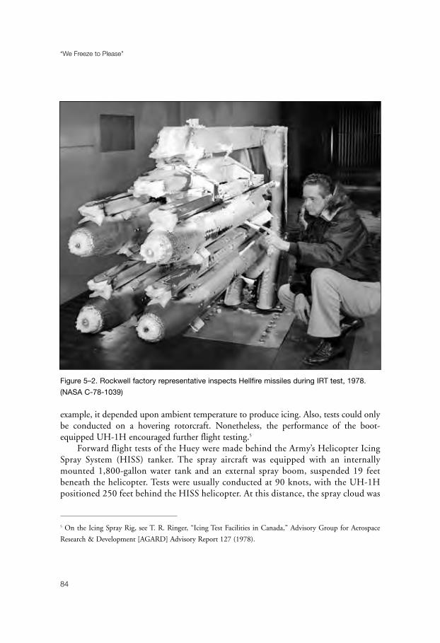
example, it depended upon ambient temperature to produce icing. Also, tests could onlybe conducted on a hovering rotorcraft. Nonetheless, the performance of the boot-equipped UH-1H encouraged further flight testing.5
Forward flight tests of the Huey were made behind the Army’s Helicopter IcingSpray System (HISS) tanker. The spray aircraft was equipped with an internallymounted 1,800-gallon water tank and an external spray boom, suspended 19 feetbeneath the helicopter. Tests were usually conducted at 90 knots, with the UH-1Hpositioned 250 feet behind the HISS helicopter. At this distance, the spray cloud was
“We Freeze to Please”
84
5 On the Icing Spray Rig, see T. R. Ringer, “Icing Test Facilities in Canada,” Advisory Group for Aerospace
Research & Development [AGARD] Advisory Report 127 (1978).
Figure 5–2. Rockwell factory representative inspects Hellfire missiles during IRT test, 1978.
(NASA C-78-1039)
35 to 40 feet wide. Although it was difficult to maintain the correct liquid watercontent and droplet size with the HISS system, the tests still provided significantinformation about the inflight performance of the de-icing system. Perhaps the mostimportant result of the HISS tests related to the durability of the Estane boots. After6 hours of artificial rain testing behind the tanker, there was no detectable erosionof the Estane6.
Erosion testing continued at Fort Rucker, Alabama, where the Estane boots withstood10 hours of sand erosion. However, 10 hours of flying in natural rain required four sepa-rate blade repairs due to the pitting and chunking of the Estane. By 1987, the conclusionhad been reached that the Goodrich boot was a feasible rotor-protection system, but thatadditional field tests were required to gain more experience with the erosion problem.7
Far more promising than the Goodrich boot as an innovative ice-protection systemfor both helicopters and fixed-wing aircraft was the Electro-Impulse De-Icing (EIDI)system that occupied a good deal of NASA’s attention during the 1980s. The use ofelectro-magnetic energy as an impulse force to remove ice had been first suggested in1937 by Rudolf Goldschmidt, a German national who was living in London. AlthoughGoldschmidt had obtained a patent for his concept, he apparently had never attemptedto build a device to test his ideas. The concept had emerged again in the mid-1960s inthe Soviet Union. I. I. Levin of the Ministry of Power and Electricity had published apaper on the possibility of employing electro-impulse force to remove frozen and stickymaterial from bunkers, transformer boxes, and other surfaces.8
The Soviets had installed the system on an Ilyushin IL-18 transport in the 1970s,then sent salesmen to Western nations to market the concept. They had shown a film ofa wing with heavy icing. In an instant, the ice had disappeared. Although it had beenimpossible to tell whether the wing was attached to an airplane in flight or had been pho-tographed in a wind tunnel, viewers had nonetheless been impressed. The Soviets hadrefused to provide any further details, had referred interested parties to Levin’s article,and had asked for $500,000 to develop the system for any aircraft.
The Russians had not gotten their $500,000, but their visit had sparked interest inthe system in Western Europe and in the United States. The French had attempted toput an electro-impulse system on an Alpha Jet, but it had not worked well. The British
Back in Business
85
6 “NASA’s Rotorcraft Icing Research Program.” The HISS system is described in the FAA’s Aircraft Icing
Handbook, vol. 2, ch. IV.7 “NASA’s Rotorcraft Icing Research Program.”8 For the EIDI story, see G. M. Zumwalt, R. L. Schrag, W. E. Bernhart, and R. A. Friedberg, “Electro-Impulse
De-Icing: Testing, Analysis and Design,” NACA CR 4175 (September 1988); and Zumwalt to Leary, 30
August 2000.

“We Freeze to Please”
86
Figure 5–3. Technician Fred Murray with traverse rig in IRT, 1979. (NASA C-79-1686)

Aircraft Corporation had tried the system in a wind tunnel, but they had found that theforce required to remove ice also destroyed the wing structure. In the United States, BellHelicopter and Lockheed had looked into the concept. Lockheed’s experiments hadappeared especially promising, but the company’s decision to leave the commercial trans-port business had ended work on the project.
Aware of Lockheed’s apparent success, NASA invited McDonnell Douglas to testEIDI in the IRT in 1981. In November, a semi-trailer arrived in Cleveland fromCalifornia with fourteen technicians and engineers, impressive capacitor banks, multiplerecording devices, and a DC-10 wing section with removable leading edges and variable-location pads for the copper coils that would carry the electro-magnetic energy.McDonnell Douglas tested the EIDI-equipped wing section in the IRT for six weeks.Sometimes the system worked, and sometimes it did not. No one knew why. With theresults deemed negative, the McDonnell Douglas people packed up and went back toCalifornia. The data from the experiments were never reduced, so NASA learned nothingfrom the tests. In any event, most individuals connected with the tests came away withthe conviction that EIDI was a fluke.
Reinmann, on the other hand, continued to see promise in EIDI. He sought tointerest a Lewis colleague, who was an expert in electro-magnetic theory, in undertakingfurther research into the system, but he was turned down. Reinmann next approached aprofessor at MIT who had published extensively on the interaction of electro-magneticwaves with various media. After talking to several of his graduate students, the professorsaid that no one was interested in pursuing research in this area. Work on the systemseemed at a dead end.9
Shortly after these disappointing results, however, EIDI again came to NASA’s atten-tion—this time during a meeting of the General Aviation Advisory Committee at Lewis.A representative of a small aircraft company complained about the limitations of pneu-matic boots and asked if NASA could come up with a better de-icing system forpiston-engine aircraft. Icing researcher Harold W. Schmidt, who was an avid privatepilot, said that EIDI might be the answer. But, he went on, NASA was reluctant to workwith the large transport manufacturers on developing the system because of the recentexperience with McDonnell Douglas. Representatives from Cessna and Beech, aircraftcompanies in Wichita, Kansas, then suggested that a study might be done through a localuniversity, with the results made public.
Following this meeting, Schmidt called Professor Glen W. Zumwalt at Wichita StateUniversity (WSU) and told him that NASA might be prepared to work with Cessna andBeech if they were partners in a quick feasibility study of EIDI that was proposed by a
Back in Business
87
9 Reinmann to Leary, 22 April 2001.

university.10 Zumwalt was at first hesitant to become involved. He reminded Schmidtthat he was an aerodynamicist who was familiar with wind tunnels, but that he had nobackground in electro-dynamics or structural dynamics. Schmidt, however, would not befended off. In the end, Zumwalt agreed to explore the idea with the two individuals whohad brought up the subject at the Advisory Committee meeting—David Ellis of Cessna
“We Freeze to Please”
88
10 David Ellis, who was chief of advanced design at Cessna, has a somewhat different recollection of these
events. He recalls that his first knowledge of the EIDI project was the result of a telephone call from
Reinmann about this “Russian system.” Reinmann told Ellis that NASA had tried to interest Boeing,
Douglas, and Lockheed in a joint project with NASA to develop EIDI, but they were not interested.
Reinmann wondered if a general aviation manufacturer might wish to join such a project. Ellis told Reinmann
that Cessna would indeed be interested. Ellis then contacted Zumwalt, who set up the WSU team. Leary tele-
phone interview with Ellis, 1 September 2000. Zumwalt, however, responded to Ellis’s recollection in caps:
“I AM QUITE SURE THAT I HEARD FIRST FROM SCHMIDT, THEN CONTACTED DAVE ELLIS.”
Zumwalt to Leary, 23 May 2001.
Figure 5–4. Inspecting IRT fan blades, 1979. (NASA C-79-324)
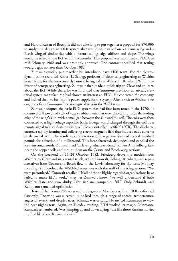
and Harold Reisen of Beech. It did not take long to put together a proposal for $70,000to study and design an EIDI system that would be installed on a Cessna wing and aBeech wing of similar size with different leading edge stiffness and shape. The wingswould be tested in the IRT within six months. This proposal was submitted to NASA inmid-February 1982 and was promptly approved. The contract specified that testingwould begin no later than October 1982.
Zumwalt quickly put together his interdisciplinary EIDI team. For the electro-dynamics, he recruited Robert L. Schrag, professor of electrical engineering at WichitaState. Next, for the structural dynamics, he signed on Walter D. Bernhart, WSU pro-fessor of aerospace engineering. Zumwalt then made a quick trip to Cleveland to learnabout the IRT. While there, he was informed that Simmons-Precision, an aircraft elec-trical system manufacturer, had shown an interest an EIDI. He contacted the companyand invited them to furnish the power supply for the system. After a visit to Wichita, twoengineers from Simmons-Precision agreed to join the WSU team.
Zumwalt adopted the basic EIDI system that had first been tested in the 1970s. Itconsisted of flat-wound coils of copper ribbon wire that were placed just inside the leadingedge of the wing’s skin, with a small gap between the skin and the coil. The coils were thenconnected to a high-voltage capacitor bank. Energy was discharged through the coil by aremote signal to a solid-state switch, a “silicon-controlled rectifier” (SCR). The dischargecreated a rapidly forming and collapsing electro-magnetic field that induced eddy currentsin the metal skin. The result was the creation of a repulsive force of several hundredpounds for a fraction of a millisecond. This force shattered, debonded, and expelled theice—instantaneously. Zumwalt had “a clever graduate student,” Robert A. Friedberg, fab-ricate the copper coils and mount them on the Cessna and Beech wing sections.
On the weekend of 23–24 October 1982, Friedberg drove the models fromWichita to Cleveland in a rental truck, while Zumwalt, Schrag, Bernhart, and repre-sentatives from Cessna and Beech flew to the Lewis laboratory for the tests. Mondaymorning, 25 October, the WSU-led team met with the staff of the icing section. “Wewere patronized,” Zumwalt recalled. “If all of the so highly regarded organizations havefailed to make EIDI work,” they let Zumwalt know, “we will understand if littleWichita State and two dinky light airplane companies fail.” Only Schmidt andReinmann remained optimistic.
Tests of the Cessna 206 wing section began on Monday evening. EIDI performedflawlessly. The wing was successfully de-iced through a range of speeds, temperatures,angles of attack, and droplet sizes. Schmidt was ecstatic. He invited Reinmann to viewthe next night’s tests. Again, on Tuesday evening, EIDI worked its magic. Reinmann,Zumwalt remembered, “was jumping up and down saying ‘Just like those Russian movies. . . Just like those Russian movies!’”
Back in Business
89

“We Freeze to Please”
90
Figure 5–5. Researcher Peggy Evanich holds a Cessna wing section in the IRT, 1980.
(NASA C-80-4021)

A second week of testing involved the Beech Bonanza wing section. Again, therewere only positive results. Two weeks of IRT testing had shown that EIDI could de-icetwo different general aviation wings with a low-energy expenditure of 800 joules per footof span during the de-icing cycle. The key to designing EIDI, Zumwalt later recalled,proved to be “getting the electro-dynamicist and the structural-dynamicist to talk to eachother,” as there were strict time interval requirements for both phenomena, and they hadto interact correctly.11
Zumwalt had met with NASA officials in the midst of these successful tests and hadsuggested a three-year program during which WSU would install and test in the IRT theEIDI system on a variety of fixed- and rotor-wing aircraft. In addition, there would beflight tests of the system on the NASA Twin Otter and on a Cessna 206. WithReinmann’s enthusiastic endorsement, NASA speedily approved Zumwalt’s proposal.Zumwalt would be project director with Schmidt as project manager. The initial mem-bers of the consortium of manufacturers were Beech, Cessna, Gates-Learjet, LearFan,Boeing, McDonnell Douglas, and Simmons-Precision. They later were joined by Rohr,Sikorsky, Bell, and Boeing-Vertol.
The first series of tests in the IRT for the new program took place between 18 and 22April 1983. There were thirty-one runs made to compare different coil-and-mount designson a Cessna 206 wing section. In August, a 6-foot section of Twin Otter wing was used forthirty-five icing runs. Some runs were made with continuous icing for up to 21 minutes, withEIDI impulses 3 to 6 minutes apart. De-icing improved after the first impulse sequence in allcases. November brought additional tests of the Twin Otter wing, plus a 38-inch section froma LearFan wing that was made of Kevlar epoxy composite. By this point in time, the energyrequired to de-ice a general aviation wing had dropped dramatically from 800 joules a foot to180 joules—comparable to the amount of energy required to power the landing lights.
The next year, 1984, saw a series of four test periods in the IRT during which EIDIwas observed on a Learjet wing, Cessna tail section, Boeing 767 slat, Falcon Fanjet engineinlet, and Bell Cobra helicopter blade. In all cases, EIDI successfully removed ice withouta problem. Flight tests during the year were equally satisfactory. In January, the NASATwin Otter, flown by Richard J. Ranaudo and Robert McKnight, made twenty-oneflights over Lake Erie while WSU’s Friedberg operated the EIDI equipment. EIDI, thepilots reported, worked better than adjacent pneumatic boots. In February and March,an EIDI-equipped Cessna 206 made fifteen flights over Wichita, following a Cessna 404tanker with spray gear. Again, the EIDI system worked without a hitch.
Results from all the EIDI tests were so promising that Reinmann decided to host asymposium at Lewis in June 1985 to review the conclusions of the three-year
Back in Business
91
11 Zumwalt to Leary, 23 May 2001.
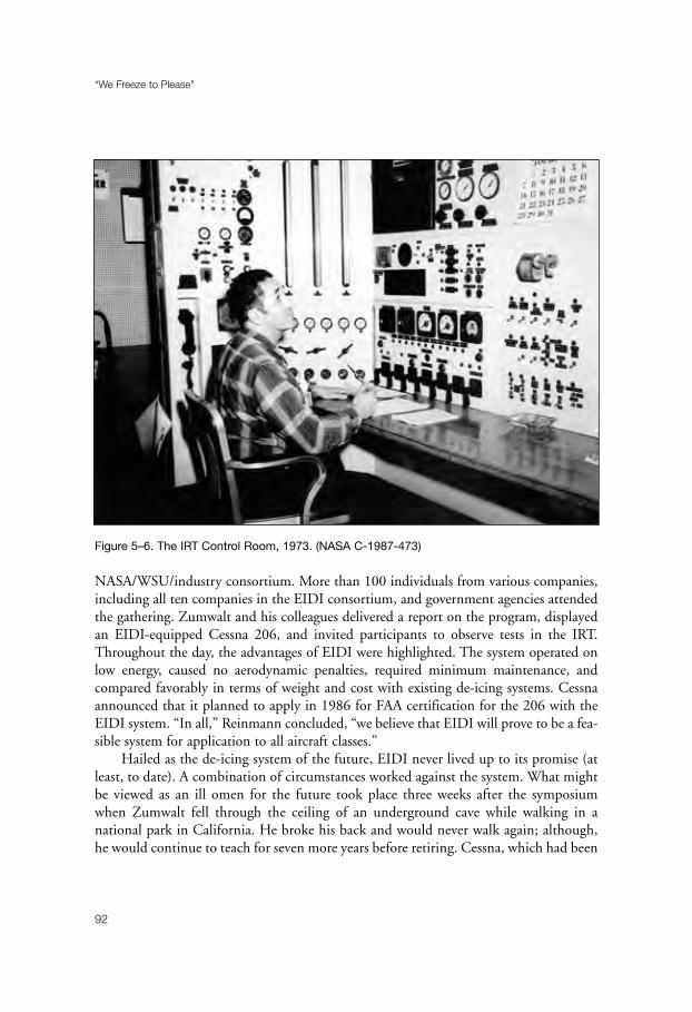
NASA/WSU/industry consortium. More than 100 individuals from various companies,including all ten companies in the EIDI consortium, and government agencies attendedthe gathering. Zumwalt and his colleagues delivered a report on the program, displayedan EIDI-equipped Cessna 206, and invited participants to observe tests in the IRT.Throughout the day, the advantages of EIDI were highlighted. The system operated onlow energy, caused no aerodynamic penalties, required minimum maintenance, andcompared favorably in terms of weight and cost with existing de-icing systems. Cessnaannounced that it planned to apply in 1986 for FAA certification for the 206 with theEIDI system. “In all,” Reinmann concluded, “we believe that EIDI will prove to be a fea-sible system for application to all aircraft classes.”
Hailed as the de-icing system of the future, EIDI never lived up to its promise (atleast, to date). A combination of circumstances worked against the system. What mightbe viewed as an ill omen for the future took place three weeks after the symposiumwhen Zumwalt fell through the ceiling of an underground cave while walking in anational park in California. He broke his back and would never walk again; although,he would continue to teach for seven more years before retiring. Cessna, which had been
“We Freeze to Please”
92
Figure 5–6. The IRT Control Room, 1973. (NASA C-1987-473)
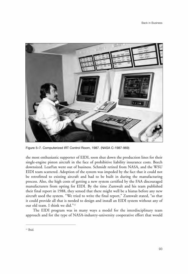
the most enthusiastic supporter of EIDI, soon shut down the production lines for theirsingle-engine piston aircraft in the face of prohibitive liability insurance costs. Beechdownsized. LearFan went out of business. Schmidt retired from NASA, and the WSUEIDI team scattered. Adoption of the system was impeded by the fact that it could notbe retrofitted to existing aircraft and had to be built in during the manufacturingprocess. Also, the high costs of getting a new system certified by the FAA discouragedmanufacturers from opting for EIDI. By the time Zumwalt and his team publishedtheir final report in 1988, they sensed that there might well be a hiatus before any newaircraft used the system. “We tried to write the final report,” Zumwalt stated, “so thatit could provide all that is needed to design and install an EIDI system without any ofour old team. I think we did.”12
The EIDI program was in many ways a model for the interdisciplinary teamapproach and for the type of NASA-industry-university cooperative effort that would
Back in Business
93
Figure 5–7. Computerized IRT Control Room, 1987. (NASA C-1987-969)
12 Ibid.

“We Freeze to Please”
94
Figure 5–8. Raymond Sotos (kneeling) and David Justavick with Hughes A-64 inlet after icing
test, 1980. (NASA C-80-1729)

become the standard for the post-1978 IRT. With limited funding, the icing branchwas compelled to seek a variety of partnership arrangements in order to obtain themaximum results from minimum expenditures. “As I look back,” Reinmann pointedout, “I now consider our limited support a blessing in disguise. It forced us to developjoint programs with a wide spectrum of industry and with other government agencies(the FAA, Air Force, Army Navy, British RAE, French, and Canadian). It forced us toavoid duplication of equipment, facilities, and expertise. We learned to bring inter-ested parties together and to get them to put their resources on the table. And finallyit forced us to go out and find more funding from other sources, by understandingindustry’s and other government agency’s needs, by showing them the advantages ofnot duplicating efforts.” Long before the approach became a Headquarter’s mantra,Reinmann emphasized, “we were already engaged in the ‘better, faster, cheaper’ way ofdoing applied research.”13
Facility manager Zager had the responsibility for scheduling the IRT. His first pri-ority was to obtain maximum usage of the tunnel. “My job,” he emphasized, “was tokeep the tunnel busy.” Zager had instructions from deputy director J. M. Klineberg andassociate director Seymour C. Himmel “that I was to make the companies happy.”Although contractors did not receive priority on scheduling, once their experiments hadbegun, Zager usually would extend their tunnel time in order to complete the tests. Thiscaused schedules to slip and gave rise to complaints. Zager and Reinmann clashed morethan once over scheduling priorities, but the facility manager rarely gave way. On oneoccasion, Zager recalled, he had to go the laboratory’s top management for support—which he received.14
Thanks in large part to Zager’s determined efforts, IRT usage reached 1,134 hoursin 1985, the first time it had exceeded 1,000 hours since reopening. Indeed, asReinmann observed at the time, the IRT had become “one of the most heavily scheduledtunnels within NASA.” The facility, however, was badly in need of renovation.Furthermore, it had become clear that plans to convert the Altitude Wind Tunnel intoan icing research facility were going to fall through.
When NASA resumed its program of icing research in 1978, officials at Lewis, aswell as potential users, had agreed that conversion of the unused AWT would be a fine
Back in Business
95
13 Reinmann to Leary, 22 April 2001.14 Zager interview. Reinmann has a somewhat different recollection. “I had a lot of support from Beheim,” he
commented, “but I don’t think I ever had to go to him to counter Zager’s scheduling. I emphasized teamwork,
and we met regularly with Zager and the IRT operators to constantly optimize the scheduling process. In any
highly scheduled facility there was bound to be some squabbling about getting time in the facility.” Reinmann
to Leary, 17 July 2001.

“We Freeze to Please”
96
Figure 5–9. Ice-phobic test rig designed by Raymond Sotos, 1980. (NASA C-80-685)

idea, allowing needed work to be done in a variety of new areas. Aircraft icing research,everyone knew, was severely hampered by the limitations of ground icing simulationfacilities such as the Canadian spray rig. While the IRT was the largest refrigerated icingtunnel in the world, it lacked the size to test many full-scale components that requiredicing protection. Also, it was limited to speeds under 300 miles per hour at sea level.Conversion of the AWT, which had not be used since 1970, would allow more accuratestudies to be made of icing problems that were encountered by high-speed fixed- androtor-wing aircraft.15
The appointment of a new director for the Lewis laboratory in 1982 seemed to offeran opportunity to persuade Headquarters to authorize the conversion. After Lewis plan-ners recommended to Andrew J. Stofan that he use the usual “honeymoon” periodaccorded to new directors to pursue five major programs, including refurbishment of theAWT, Stofan selected Brent Miller to form an AWT project office. Reinmann, in turn,was told to add an icing group to the planning office.16
Over the next three years, the scope of the project grew significantly. It was diffi-cult to “sell” the conversion of the AWT into an icing research facility when it wouldcost $10 to $20 million to support a program with an annual budget of $1 to $2 mil-lion. Under the circumstances, it was not surprising that the project office began toemphasize the many uses to which a refurbished AWT could be put. By 1985, plannerswere arguing that the AWT conversion would provide the aeronautical industry with “aneeded, truly unique, and diverse wind tunnel for future propulsion system integrationand icing R & D.” Endorsed by the Department the Defense, the FAA, and industry,the new facility would “play a major role in maintaining U.S. superiority in aeronauticswell into the 21st century.”17
It all sounded fabulous. The cost for the conversion, however, had also become fab-ulous. The original $10 to $20 had risen to $150 million—and was growing. As Beheimhad warned earlier, the decision to go ahead with the renovations would be “highlydependent on budgetary restraints.” He was proved correct; the project priced itself outof existence.18
The three years had not been wasted for the icing group in the project office. A greatdeal had been learned about icing systems for wind tunnels. Researchers William Olsen
Back in Business
97
15 B. J. Blaha and R. J. Shaw, “The NASA Altitude Wind Tunnel—Its Role in Advanced Icing Research and
Development,” a paper presented at the 23rd Aerospace Sciences Meeting of the AIAA, Reno, Nevada, 14–17
January 1985.16 Dawson, Engines and Innovation, pp. 213–14.17 Blaha and Shaw, “The NASA Altitude Wind Tunnel.” 18 Reinmann interview.

“We Freeze to Please”
98
Figure 5–10. Raymond Sotos (left) and David Justavick during U.S. Air Force ice-phobic tests,
1980. (NASA C-80-2923)

and James Newton, for example, had undertaken a major study to find out where thewater went after it left the spray nozzles and passed through the test section as an icingcloud. By collecting and weighing the ice that froze on the turning vanes, fan blades, andbetween the fins of the heat exchanger, Olsen and Newton were able to determine whereand how much water was deposited at various points along the tunnel loop. “Nothinglike this had ever been attempted before,” Reinmann pointed out. “This was a very phys-ically difficult job, and I always considered it a highlight of the history of our icingprogram.”19
Although not prepared to spend the large amount of money to refurbish the AWT,NASA Headquarters did approve a major modification program for the heavily used IRT.In February 1986, the tunnel was shut down. It would not reopen until January 1988.Manager Zager was in charge of this modernization project. Under his watchful eye,improvements were made in the following six major areas:
1. New spray nozzles and an aerodynamically designed spray bar that had beendeveloped for the AWT were placed in the IRT. Instead of the previous six spray bars andseventy-seven nozzles, the new arrangement featured eight bars. In addition to the stan-dard air-assisted nozzles with a tube diameter of 0.025 inches, the new system alsoincluded a modified nozzle (mod-1) that had been designed by Olsen and featured a tubediameter of 0.0155 inches. When using standard nozzles, the bars contained ninety-fournozzles. With the mod-1 configuration, an additional nozzle was added. At 145 miles perhour, the standard nozzles produced a uniform icing cloud that measured 3 feet by 4 feet.With the mod-1 nozzles, the size of the cloud was 2 feet by 3 feet, but it more closelyapproximated the lower liquid content of natural icing clouds. Cloud uniformity variedwith airspeed. At 70 miles per hour with standard nozzles, the cloud was uniform overmuch of the test area; at 220 miles per hour, the cloud shrank to 1.5 feet to 2.5 feet.
2. A new 5,000-hp drive motor replaced the motor that had been installed in 1944. 3. Most noticeable of all the innovations was a Westinghouse Distributed Process
Control System, which provided programmable, digital control of the drive motor,refrigeration system, spray bar system, and other support systems. Prior to this, the IRThad used analog controls with a huge bank of manometers and paper recorders. Watercame into the tiny control room, where flow rates and pressures were set by flow controlvalves. Three to four people crowded into the room to take data and to photograph themanometer board. It was a laborious, time-consuming process.
The computerized control system, the first time such a system was used at Lewis,brought the IRT up to state of the art. Operators now controlled water and air pressure,wind speed, and temperature by pressing keys on a keyboard, while they observed con-
Back in Business
99
19 Reinmann to Leary, 1 June 2001.

“We Freeze to Please”
100
Figure 5–11. Raymond Sotos views an A-10 inlet in the IRT, 1981. (NASA C-81-177)

ditions in the tunnel on a computer screen. Whereas it was possible to take only about20 data points per hour (excluding manometers) with the analog system, researcherscould now obtain up to 250 bits of information about the IRT and the model eachsecond and display the data or record it for later analysis. Zager, however, retained amanometer board in the back room of the new control room to watch the compressorprofile. He was apprehensive about the effect on the new system of a sudden loss ofpower. If not careful in handling the airflow when starting up and shutting down thetunnel, the compressor could wipe out the blades. (The manometer board was promptlyremoved upon Zager’s retirement.)20
4. The new computerized control system was housed in a room that not only wasthree times larger than the old room, but it also featured vastly improved acoustics.
5. All wooden floors were replaced with concrete flooring. After construction was completed, the tunnel underwent nearly seven months of
calibration. This was a crucial process, as the ability of the IRT to simulate flight throughnatural icing clouds depended upon the calibration of airspeed, temperature, turbulencelevel, liquid water content, and droplet size. Calibration of the spray nozzles increasedthe upper limit of mean effective drop diameter from 20 to 40 microns, therebyincreasing the range of natural icing conditions that could be simulated. By the timeeverything was finished, NASA had the finest icing research facility in the world.21
NASA’s refurbished tunnel also served as a model in many ways for two new icingresearch tunnels. BFGoodrich Aerospace had dismantled its original icing tunnel in the1970s. In 1986, the company decided to build a new tunnel for its Ice ProtectionSystems Division at Uniontown, Ohio. Goodrich wanted to test and develop new ice-protection products, especially the Pneumatic Impulse Ice Protection System (PIIP). Thegoals for this advanced system, which employed a 10-millisecond pulsed inflation to dis-tort the surface of the boot momentarily, were to minimize boot intrusion into theairstream, require less ice thickness for removal, and better resist erosion.
“We called our friends at NASA Lewis to help,” facility manager David Sweetrecalled. “They openly shared with us the icing spray technology used in the IRT thatallowed them to best replicate a natural icing cloud.” Completed in 1988, the Goodrichtunnel had a subsonic, closed-loop configuration, with a refrigeration system in thecenter of the loop that could lower temperatures to –25°F. The test section, 5 feet in
Back in Business
101
20 Zager interview.21 John J. Reinmann, Robert J. Shaw, and Richard J. Ranaudo, “NASA’s Program on Icing Research and
Technology,” NASA TM-101989 (1989), first delivered as a paper for the Symposium on Flight in Adverse
Environmental Conditions, Sponsored by the Flight Mechanics Panel of AGARD, Gol, Norway, 8–12 May
1989.

length, measured 44 inches high and 22 inches wide. An 80-inch-diameter fan, drivenby a 200-horsepower rotary motor, produced airspeeds of up to 210 miles per hour. Fivespray bars used twenty NASA-designed standard and mod-1 nozzles.22
NASA technology also assisted in the construction of a new Boeing icing tunnel.The existing tunnel at Boeing had an 18-inch by 30-inch test section and was used onlyfor development work. With an upcoming program for the advanced 777 transport,Boeing decided that the company could save a good deal of money by building a largerfacility to help with the airplane’s icing certification in 1986. George E. Cain was respon-sible for designing and building a new tunnel with 4-foot by 6-foot and 5-foot by 8-foottest sections. And the job had to be done within three years. “My first action,” he
“We Freeze to Please”
102
Figure 5–12. Electro-impulse de-icing equipment for McDonnell Douglas tests in the IRT, 1981.
(NASA C-81-6007)
22 David Sweet to Leary, 24 May 2000.

recalled, “was to tour icing tunnel facilities in the U.S. and see what was out there andwhere their problems were.”
Cain contacted Zager and arranged to visit the IRT. He spent several days at thefacility, “finding out what their problems were and what would they change if they weregoing to build a new tunnel.” As a result of his discussions with Zager, Cain included inthe design concept for the Boeing Research Aerodynamic Icing Tunnel (BRAIT) signifi-cant modifications of the heat exchanger and spray bar system. The BRAIT facility, whichopened in 1989, saw improvements on the Lewis facility, especially in the areas of nozzlecontrol and airflow. Boeing would later share these advances with NASA. “Ever since thebeginning of our relationship with NASA,” Cain observed, “we have maintained an open-door policy to discuss operational problems with each of our facilities . . . . We have anexcellent relationship with NASA.”23
While NASA’s new tunnel was taking shape, the old tunnel was being recognized for itscontribution to icing research by the American Society of Mechanical Engineers (ASME).In 1985, Robert Graham, NASA Lewis liaison with the ASME, had suggested to Reinmannthat the IRT might be a good candidate for designation as a historic engineering landmark.At the time, Reinmann had taken no action on Graham’s proposal and stuffed the ASMEbrochure on engineering landmarks in his desk drawer. Two years later, however, after notingthe extensive historical work that William Olsen had done in support of the AWT modifi-cation program, especially on the Carrier system, Reinmann pulled out the ASME brochure,handed it to Olsen, and suggested that he undertake the project. Olsen was delighted withthe assignment. “Bill,” Reinmann recalled, “poured his heart into this.”24
Assisted by Virginia P. Dawson, a contract historian, Olsen put together a packageof documents and photographs in support of the nomination. He listed three reasonswhy the IRT should be considered historically significant. First, he observed that most ofthe current aircraft icing technology had been researched, developed, and tested in theIRT. Second, the IRT was the largest refrigerated icing tunnel in the world. Finally, at21,000 tons capacity, the refrigeration plant used by the IRT remained the largest directexpansion refrigeration system in the world. The heat exchanger in the IRT featured arevolutionary design that Willis Carrier considered to be his greatest engineering achieve-ment. Olsen also included a diagram of the IRT’s innovative spray nozzles.25
The ASME accepted Olsen’s nomination and agreed to add the IRT to such otherlandmarks as the Five-Foot Wind Tunnel at Wright Field, the Link Trainer, and the
Back in Business
103
23 George E. Cain to Leary, 3 November 2000.24 Reinmann to Leary, 1 June 2001.25 Olsen and Dawson to ASME, “Nomination for Designation of Historical Engineering Landmark,” n.d.,
NASA History Office.

Sikorsky VS-300 Helicopter. The ceremony took place at Lewis on 20 May 1987. Manyof the individuals who were responsible for the design and construction of the IRT werepresent, along with the researchers who had worked in the facility during the 1940s and1950s. The ASME formally designated the IRT as the 21st International HistoricMechanical Engineering Landmark and placed a plaque on the building that proclaimedthe following:
The icing research tunnel is the oldest and largest refrigerated icingwind tunnel in the world. The world’s aircraft fly safely through icingclouds because of the technology developed in this tunnel. Two importantachievements of the installation are the unique heat exchanger and thespray system that simulates a natural icing cloud of tiny droplets.26
“We Freeze to Please”
104
26 Program, “An International Historic Mechanical Engineering Landmark: Icing Research Tunnel,” 20 May
1987, History Office, GRC.
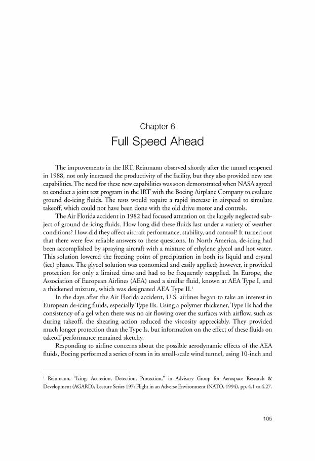
105
Chapter 6
Full Speed Ahead
The improvements in the IRT, Reinmann observed shortly after the tunnel reopenedin 1988, not only increased the productivity of the facility, but they also provided new testcapabilities. The need for these new capabilities was soon demonstrated when NASA agreedto conduct a joint test program in the IRT with the Boeing Airplane Company to evaluateground de-icing fluids. The tests would require a rapid increase in airspeed to simulatetakeoff, which could not have been done with the old drive motor and controls.
The Air Florida accident in 1982 had focused attention on the largely neglected sub-ject of ground de-icing fluids. How long did these fluids last under a variety of weatherconditions? How did they affect aircraft performance, stability, and control? It turned outthat there were few reliable answers to these questions. In North America, de-icing hadbeen accomplished by spraying aircraft with a mixture of ethylene glycol and hot water.This solution lowered the freezing point of precipitation in both its liquid and crystal(ice) phases. The glycol solution was economical and easily applied; however, it providedprotection for only a limited time and had to be frequently reapplied. In Europe, theAssociation of European Airlines (AEA) used a similar fluid, known at AEA Type I, anda thickened mixture, which was designated AEA Type II.1
In the days after the Air Florida accident, U.S. airlines began to take an interest inEuropean de-icing fluids, especially Type IIs. Using a polymer thickener, Type IIs had theconsistency of a gel when there was no air flowing over the surface; with airflow, such asduring takeoff, the shearing action reduced the viscosity appreciably. They providedmuch longer protection than the Type Is, but information on the effect of these fluids ontakeoff performance remained sketchy.
Responding to airline concerns about the possible aerodynamic effects of the AEAfluids, Boeing performed a series of tests in its small-scale wind tunnel, using 10-inch and
1 Reinmann, “Icing: Accretion, Detection, Protection,” in Advisory Group for Aerospace Research &
Development (AGARD), Lecture Series 197: Flight in an Adverse Environment (NATO, 1994), pp. 4.1 to 4.27.
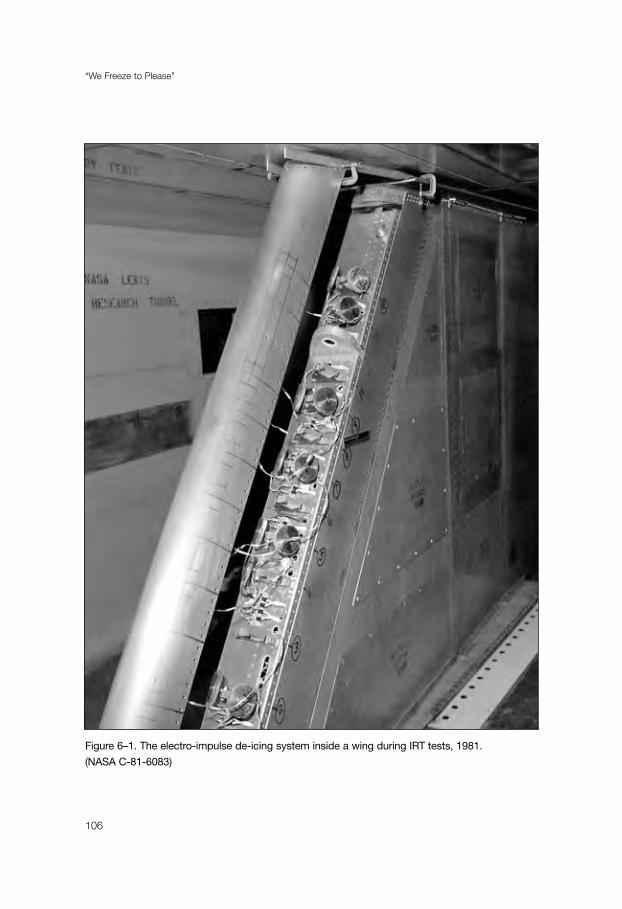
“We Freeze to Please”
106
Figure 6–1. The electro-impulse de-icing system inside a wing during IRT tests, 1981.
(NASA C-81-6083)

24-inch airfoils in 1982. Results of this investigation indicated that both the undilutedType I and Type II fluids failed to completely flow off the wing prior to reaching liftoffvelocity. The remaining residue, the researchers noted, formed a rough, reticulated sur-face, causing a measurable loss in lift and an increase in drag.2
Concerned about the results of the Boeing tests, the AEA sponsored a research pro-gram in 1984 with the von Karman Institute for Fluid Dynamics of Brussels, Belgium,to further investigate the possibility of aerodynamic penalties caused by the fluids. Usinga 4.92-foot-chord two-dimensional model, the Institute conducted a series of experi-ments on the effect of the fluids on takeoff performance during subfreezingtemperatures. The results of these tests generally agreed with Boeing’s findings. In thewake of this troubling conclusion, AEA asked Boeing to perform a flight test investiga-tion of the fluid effects.
Before the flight tests could take place, however, two major accidents made the dan-gers of improper de-icing dramatically clear. At 5:34 A.M. on 12 December 1985, anArrow Air DC-8 landed at Gander, Newfoundland, for refueling on a flight with U.S.military personnel from Europe to the United States. Although light freezing drizzle wasfalling during the refueling process, the pilot did not request de-icing. Taking off at 6:45A.M., the aircraft pitched up after rotation, banked to the right, and struck the ground3,000 feet beyond the end of the runway. The crash killed all 248 passengers and eightcrew members. Although the investigation of the accident took place amidst controversyabout the possibility that the plane had been brought down by a bomb, a majority of theCanadian investigating board and a judicial review concluded that the DC-8 had stalleddue to ice contamination of the leading edges and upper surfaces of the wing.3
A second major accident took place on 15 November 1987. Moderate snow wasfalling as a Continental DC-9 prepared to depart Denver. The airplane was de-iced, but27 minutes elapsed before the flight received takeoff clearance. Although company proce-dures called for additional de-icing if delays exceeded 20 minutes, the pilot elected tocontinue. The results were similar to the Arrow Air crash. The DC-9 stalled after rotationand impacted upon the right side of the runway. Twenty-eight people lost their lives.4
Full Speed Ahead
107
2 The work on de-icing fluids is summarized in Reinmann, Shaw, and Ranaudo, “NASA’s Program on Icing
Research and Technology,” NASA TM 101989 (1989), and Eugene G. Hill and Thomas A. Zierton, “Flight
and Wind Tunnel Tests of the Aerodynamic Effects of Aircraft Ground Deicing/Anti-Icing Fluids,” a paper pre-
sented at the 29th Aerospace Sciences Meeting of the American Institute of Aeronautics and Astronautics,
Reno, Nevada, 7–10 January 1991.3 See New York Times, 9 December 1988; Toronto Star, 15 March 1989, and 19 July 1989.4 For an excellent summary of icing-related accidents between 1946 and 1996, see the special issue of Flight
Safety Digest, “Protection Against Icing: A Comprehensive Overview,” June/September 1997.

“We Freeze to Please”
108
Figure 6–2. IRT spray bars, 1982. (NASA C-82-4308)
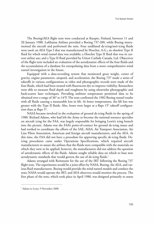
The Boeing/AEA flight tests were conducted at Kuopio, Finland, between 11 and20 January 1988. Lufthansa Airlines provided a Boeing 737-200, while Boeing instru-mented the aircraft and performed the tests. Four undiluted de-icing/anti-icing fluidswere used: an AEA Type I that was manufactured by Hoechst, A.G.; an obsolete Type IIfluid for which wind tunnel data was available; a Hoechst Type II fluid that was in cur-rent airline use; and a Type II fluid provided by Union Carbide Canada, Ltd. Objectivesof the flight tests included an evaluation of the aerodynamic effects of the four fluids andthe accumulation of a database for extrapolating data from a more comprehensive windtunnel investigation in the future.
Equipped with a data-recording system that monitored gross weight, center ofgravity, engine parameters, airspeed, and acceleration, the Boeing 737 made a series oftakeoffs in various configurations as video and photographic records were made of thefour fluids, which had been treated with fluorescent dye to improve visibility. Researcherswere able to measure fluid depth and roughness by using ultraviolet photographic andback-scatter laser techniques. Prevailing ambient temperature permitted data to beobtained over a range of 36° to 14°F. The tests confirmed the 1982 Boeing tunnel resultswith all fluids causing a measurable loss in lift. At lower temperatures, the lift loss wasgreater with the Type II fluids. Also, losses were larger at a flaps 15° takeoff configura-tion than at flaps 5°.
NASA became involved in the evaluation of ground de-icing fluids in the spring of1988. Richard Adams, who had left the Army to become the national resource specialiston aircraft icing for the FAA, was largely responsible for bringing Lewis’s icing branchinto the picture. Adams was the FAA’s point-of-contact for ground de-icing issues andhad worked to coordinate the efforts of the SAE, AIAA, Air Transport Association, AirLine Pilots Association, American and foreign aircraft manufacturers, and the AEA. Atthis time, the FAA did not have a procedure for approving specific de-icing fluids. De-icing procedures came under Operations Specifications, which required aircraftmanufacturers to assure the airlines that the fluids were compatible with the materials onwhich they were to be applied; however, the manufacturers did not address the questionof aerodynamic effects of the fluids. Adams sought reliable data on which to base newaerodynamic standards that would govern the use of de-icing fluids.5
Adams arranged with Reinmann for the use of the IRT following the Boeing 737flight tests. The experiments would be a joint effort by NASA, Boeing, the AEA, and var-ious fluid manufacturers. Boeing would provide the wind tunnel models and conduct thetests; NASA would operate the IRT; and AEA observers would monitor the process. Thefirst phase of the tests, which took place in April 1988, was designed primarily to assess
Full Speed Ahead
109
5 Adams to Leary, 9 November 2000.
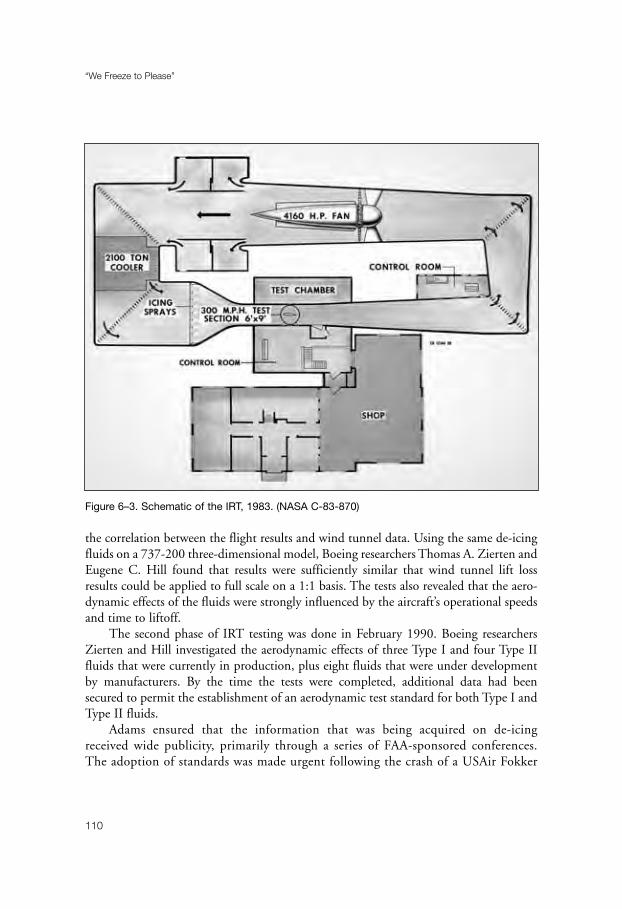
the correlation between the flight results and wind tunnel data. Using the same de-icingfluids on a 737-200 three-dimensional model, Boeing researchers Thomas A. Zierten andEugene C. Hill found that results were sufficiently similar that wind tunnel lift lossresults could be applied to full scale on a 1:1 basis. The tests also revealed that the aero-dynamic effects of the fluids were strongly influenced by the aircraft’s operational speedsand time to liftoff.
The second phase of IRT testing was done in February 1990. Boeing researchersZierten and Hill investigated the aerodynamic effects of three Type I and four Type IIfluids that were currently in production, plus eight fluids that were under developmentby manufacturers. By the time the tests were completed, additional data had beensecured to permit the establishment of an aerodynamic test standard for both Type I andType II fluids.
Adams ensured that the information that was being acquired on de-icingreceived wide publicity, primarily through a series of FAA-sponsored conferences.The adoption of standards was made urgent following the crash of a USAir Fokker
“We Freeze to Please”
110
Figure 6–3. Schematic of the IRT, 1983. (NASA C-83-870)

F-28 on 22 March 1992. The aircraft had been de-iced twice before leaving the gateat New York’s LaGuardia Airport, but 35 minutes had elapsed between the last de-icing and takeoff. The Fokker stalled after rotation and came to rest in Flushing Bay(at the end of the runway). There were twenty-seven fatalities in an accident that wasgiven extensive publicity.6
Full Speed Ahead
111
Figure 6–4. Fairchild SF340 in IRT, 1983. (NASA C-83-1160)
6 New York Times, 23 March 1992. Following this accident, Reinmann was asked to appear on a local TV show
in Cleveland, together with a survivor of the crash. “I used some graphics and a model airplane to illustrate
how ice buildup on the wings degrades aerodynamic performance and the consequences,” he recalled. “The
next day, a captain from one of the major airlines called me from California, his home base. He said that he
had watched the show while he was on a holdover in Cleveland, and he wanted me to know that it was the first
time that he really understood how icing affected takeoff performance. He said that when he got on the air-
plane he mentioned the show to his copilot, and he too had watched it and found it helpful. The captain talked
to me for about an hour, telling me about his experiences in icing.” Reinmann to Leary, 22 April 2001.

While the NTSB faulted the pilot for early rotation, the accident investigators leviedtheir major criticism at the FAA. The probable cause of the accident, the NTSB con-cluded, was the failure of the FAA and the airline industry to provide flight crews withprocedures, requirements, and criteria for de-icing when facing delayed departures.7
In the wake of the USAir accident, the FAA moved rapidly to formulate new ruleson aircraft icing before the winter of 1992–93. Effective 1 November, the new regula-tions specified the maximum allowable time between de-icing and takeoff. Additionalinformation followed on the characteristics of various de-icing fluids, largely based on thetesting that had been done between 1982 and 1990.8
“We Freeze to Please”
112
Figure 6–5. Icing section in 1985. Standing: (L/R) John Reinmann, Nikola Juhasz, Andrew
Reehorst, Sandy Kosakowski, Robert Ide, Gary Ruff, Peggy Evanich, Kevin Mikkelson, James
Newton. Kneeling: (L/R) Mark Potapczuk, Thomas Miller, Robert Shaw, Gary Horsham, William
Olsen, Kevin Leffler. (NASA C-85-3120)
7 Washington Post, 21 September 1992.8 FAA Press Release, 25 September 1992.

Reinmann took considerable pleasure in NASA’s contribution to the developmentof ground de-icing standards. The modernized IRT had performed superbly, allowing theresults of scale-model tests to be extrapolated to full size. Even Boeing researcher Ziertenseemed impressed and told Reinmann that the IRT’s productivity was at least as high asthat of the Seattle manufacturer. Years later, when asked about the major accomplish-ments during his sixteen years as head of icing research, Reinmann placed the work onground de-icing near the top of his list.9
NASA also participated in a joint program with McDonnell Douglas Aerospace(MDA) to study the effect of icing on the performance of advanced, high-lift airfoils. Inorder to compete with Airbus, U.S. manufacturers were working on a simplified three-element wing design that would improve performance and consume less fuel. Early in
Full Speed Ahead
113
Figure 6–6. Sikorsky PFM awaiting installation in the IRT, 1986. (NASA C-86-4570)
9 Reinmann interview.

“We Freeze to Please”
114
Figure 6–7. John Reinmann (L) and Thomas Bond with Sikorsky PFM in the IRT, 1989.
(NASA C-1989-9699)

1992 when NASA and MDA discussed possible icing programs of mutual interest, thethree-element wing design was a natural candidate for investigation.10
MDA designed and fabricated a model of the three-element wing specifically forvertical installation in the IRT. It consisted of a slat with a hot-air de-icing system,a main element assembly, and a large-chord single-segment flap. Tests began in thesummer of 1993 under the direction of project leader Jaiwon Shin. They revealedthat the slat reacted to icing much like the leading edge of a single-element airfoil,whereas the main element assembly and flap were much less sensitive. Also, theentire lower surface of the flap accreted ice under all icing conditions, with signifi-cant buildups on the trailing edge in most cases. Finally, the gaps between theelements did not suffer any ice contamination for the icing conditions and flap set-tings used in the tests.11
Alan Kehlet, vice president for advanced program and technology/transport air-craft at MDA, considered the tests “very productive.” The quality and amount ofdata that had been collected, he wrote to NASA, “is due in large part to the workingrelationship established between the NASA team and McDonnell Douglas per-sonnel, and the quality support received from the NASA engineers and techniciansinvolved in this test.”12
Additional testing took place in the summer of 1994 to add to the database on thethree-element system and to explore at greater length the possible effects of gap sizes. In some177 icing runs, Shin and his team found that slat-ice accretion was more sensitive to angle-of-attack changes than the main element or flap. Also, changing flap settings had a smallereffect on ice accretion than did changing the angle of attack. Work in the IRT ended at thispoint; although, additional experiments were performed in Langley’s Low-TurbulencePressure Tunnel using ice shapes that had been generated during the IRT tests.13
NASA’s cooperation with McDonnell Douglas and Boeing were the types of devel-opmental programs that generated a good deal of favorable publicity for the space agency.Unlike the pre-1958 era, the post-1978 years saw far more time devoted to this kind ofprogram than to more basic research. By early 1990s, with the IRT in use over 1,000
Full Speed Ahead
115
10 Reinmann, “Cooperative NASA/Industry/Agency/University Programs,” NASA-Industry Workshop on
Aircraft Icing, NASA Lewis Research Center, 27–29 July 1993.11 Dean Miller, Jaiwon Shin, and David Sheldon (NASA); Abdolah Khodadoust and Peter Wilcox (MDA); and
Tammy Langhals (NYMA, Inc.), “Further Investigations of Icing Effects on an Advanced High-Lift Multi-
Element Airfoil,” NASA TM 106947 (1995).12 Lewis News, 12 August 1994.13 Ibid.; Miller, et al., NASA TM 106947.

hours a year, approximately 60 percent of tunnel time was being spent in direct supportof civilian and military manufacturers.14
Reinmann, however, also ensured that his section made a strong effort to betterunderstand the phenomena of icing and to develop better tools to predict its effects. Theadvent of high-speed computers, for example, opened up the possibility of developing acomputer program to predict ice-accretion shapes, design aircraft de-icing systems, andanalyze performance degradation due to icing. The increasing cost of flight tests for icingcertification certainly provided strong motivation to employ aircraft icing analysesmethods wherever possible. Reinmann assigned primary responsibility for this area ofresearch to his deputy, Robert J. Shaw. “I gave him a lot of freedom,” Reinmann recalled,“and he loved it.”15
“We Freeze to Please”
116
Figure 6–8. NASA’s Twin Otter behind Army’s HISS, 1988. (NASA C-88-1728)
14 Les Dorr, Jr., “We Freeze to Please . . .,” NASA Magazine, spring 1993, pp. 26–30.15 Reinmann interview.
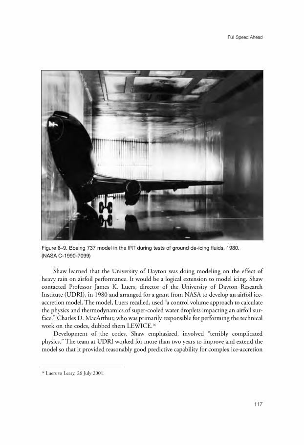
Shaw learned that the University of Dayton was doing modeling on the effect ofheavy rain on airfoil performance. It would be a logical extension to model icing. Shawcontacted Professor James K. Luers, director of the University of Dayton ResearchInstitute (UDRI), in 1980 and arranged for a grant from NASA to develop an airfoil ice-accretion model. The model, Luers recalled, used “a control volume approach to calculatethe physics and thermodynamics of super-cooled water droplets impacting an airfoil sur-face.” Charles D. MacArthur, who was primarily responsible for performing the technicalwork on the codes, dubbed them LEWICE.16
Development of the codes, Shaw emphasized, involved “terribly complicatedphysics.” The team at UDRI worked for more than two years to improve and extend themodel so that it provided reasonably good predictive capability for complex ice-accretion
Full Speed Ahead
117
Figure 6–9. Boeing 737 model in the IRT during tests of ground de-icing fluids, 1980.
(NASA C-1990-7099)
16 Luers to Leary, 26 July 2001.
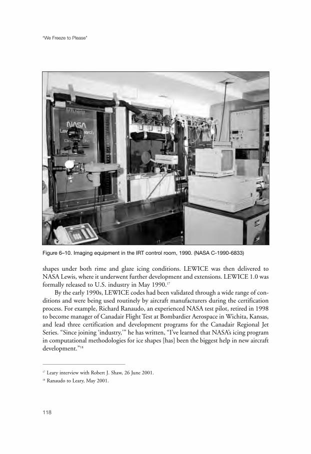
shapes under both rime and glaze icing conditions. LEWICE was then delivered toNASA Lewis, where it underwent further development and extensions. LEWICE 1.0 wasformally released to U.S. industry in May 1990.17
By the early 1990s, LEWICE codes had been validated through a wide range of con-ditions and were being used routinely by aircraft manufacturers during the certificationprocess. For example, Richard Ranaudo, an experienced NASA test pilot, retired in 1998to become manager of Canadair Flight Test at Bombardier Aerospace in Wichita, Kansas,and lead three certification and development programs for the Canadair Regional JetSeries. “Since joining ‘industry,’” he has written, “I’ve learned that NASA’s icing programin computational methodologies for ice shapes [has] been the biggest help in new aircraftdevelopment.”18
“We Freeze to Please”
118
Figure 6–10. Imaging equipment in the IRT control room, 1990. (NASA C-1990-6833)
17 Leary interview with Robert J. Shaw, 26 June 2001.18 Ranaudo to Leary, May 2001.

Work on LEWICE continued during the 1990s, with releases of versions 1.6 inJune 1995 and 2.0 in February 1999. The codes, Shaw noted, work well in certainareas but not in warm temperature icing, due to the icing physics associated with thoseconditions. But the future of computer simulations remains bright. The developmentof three-dimensional codes has brought new challenges to scientists—and promisesgreat rewards.19
Validation of computer codes during the 1980s and 1990s involved flight tests andexperiments in the IRT. Reinmann appreciated the value of flight testing and lent hissupport to the work of the group, although not as much as the section sometimes desired.For one thing, flight testing was expensive, costing about one-third of the icing branch’s$1 to $2 million annual budget. Also, Reinmann noted, the flight group usually wantedto build a program around the airplane, whereas Reinmann wanted to use it as part of a broader icing effort, such as the validation of computer codes, testing advanced ice-protection concepts, and assessing the effects of ice on airplane performance.
Certainly, the Twin Otter that was used for icing research had proved an extremelyuseful tool for the work of the icing section. The airplane was equipped with electro-thermal anti-icers on its propellers, engine inlets, and windshields. It had non-standardpneumatic boots on the vertical stabilizer, wing struts, and landing struts, and standardboots on wings and engine nacelles. Researchers measured leading edge ice shapes with astereo photographic system. A wake survey probe mounted on the wing behind the areawhere the photos were taken recorded wing section drag, while a noseboom providedinformation on airspeed, angle of attack, and sideslip.
Averaging about thirty missions a year since 1981, the Twin Otter, usually flown byRanaudo, had numerous encounters with natural icing clouds, during which ice wasallowed to build up on the leading edge of the wing. The aircraft was then flown intoclear air so that stereo photographs could be taken of the ice shapes and performancedegradation measured. This inflight data was then used both to validate computer codesand to confirm that the IRT was adequately simulating natural icing.20
In addition to validating computer codes, the IRT also was used extensively in scalemodeling programs, especially for helicopters. The rotorcraft industry was one of thefastest growing segments of civil aviation during the 1980s, and demands increased forall-weather capability. Helicopter companies, as noted earlier, had been using the IRTsince the early 1960s to test engine inlets and ice-protection systems on stationary rotorblades, but full-scale main rotors could only be tested in actual icing conditions. With
Full Speed Ahead
119
19 Shaw interview.20 For an example of this work, see R. J. Ranaudo, et al., “The Measurement of Aircraft Performance and
Stability and Control After Flight Through Natural Icing Conditions,” NASA TM 87265 (1986).
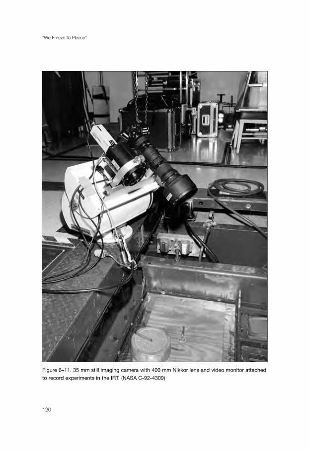
“We Freeze to Please”
120
Figure 6–11. 35 mm still imaging camera with 400 mm Nikkor lens and video monitor attached
to record experiments in the IRT. (NASA C-92-4309)

their short range and slow speed, helicopters usually had to wait until suitable icing con-ditions were available close to their home base; that is to say, they had to wait for theweather to come to them, whereas fixed-wing aircraft could fly to icing weather. Flighttesting was both dangerous and expensive. And it could take years to acquire the dataneeded for FAA certification or military qualification. A possible answer to this problemwould be the testing of a properly scaled model in the IRT.
In 1985, NASA and the Army sponsored the formation of the Rotor IcingConsortium, which included the four major helicopter manufacturers and Texas A & MUniversity. The consortium selected a model one-sixth of the size of a Sikorsky UH-60Blackhawk helicopter for testing in the IRT. Heavily instrumented, the Blackhawk wasdesignated a Powered Force Model (PFM). NASA’s responsibility would be to providethe facility and develop testing techniques.
Thomas H. Bond, the icing section’s lead researcher for the project, suggested that thebest way to explore rotor icing test procedures for the PFM would be to first test a simplermodel rotor in the IRT. The Lewis laboratory, he told the consortium, had designed andbuilt a rugged and heavy instrumented Bell OH-58 Kiowa tail rotor rig in 1980. Themodel, however, had never been tested and was in storage. He proposed that the rig berefurbished and serve as a test case for the PFM experiments. The consortium agreed.
The OH-58 rig was an ingenious creation of the Lewis model shop. It consisted ofthe tail shaft, hub, teetering components, and rotor blades for an OH-58. This assembly,5 feet in diameter, was then mated to a NASA-designed drive force by a 40-horsepowerelectric motor. A 7-foot drive shaft allowed the rotor blades to turn in the middle of theIRT test section while the drive system remained underneath the tunnel turntable. Ahydraulically operated center tube controlled the collective pitch of the rotor blades andenabled the blade angle to be changed quickly, if desired.21
Tests of the OH-58 rig took place in August, September, and November 1988.Concerned about the potential failure of the rotating hardware, Lewis technicians puttogether a set of armor plates on rails that was designed to protect vulnerable areas of thetunnel wall. Because these plates blocked the normal viewing area for tests, video cam-eras were installed to monitor the procedure and collect data.
As the tests began, the rig operator brought the tail rotor up to speed. Next, thetunnel’s fan was turned on. Once tunnel conditions had stabilized, the operator adjustedthe collective pitch to a 5°-forward tilt to simulate forward flight and started the data acqui-sition hardware. The spray was then introduced, the icing cloud formed, and the data wasrecorded on the rate of ice accretion. After the test run, photographs were taken of theresultant ice formation, the shape of the formation was traced, and ice molds were made.
Full Speed Ahead
121
21 For a detailed description of the scale model helicopter experiments, see Lewis News, 30 March 1990.

The OH-58 tests proceeded without incident. As Bond had hoped, they paved the wayfor the PFM experiments. Lessons had been learned about coordination procedures formodel and tunnel, and the best methods for observing and documenting rotor ice accretionand shedding. Also, the tests had led to establishing safety and emergency procedures.
PFM testing took place over a ten-week period in the fall of 1989. The Sikorsky-built Blackhawk model was a far more sophisticated creation than the OH-58 rig. Itfeatured a six-component internal force balance from which measurements of main rotorperformance could be made. The four-bladed main rotor consisted of generic NACA0012 airfoils, 6 feet in diameter. (A true one-sixth-scale model of the Blackhawk mainrotor would have been 9 feet in diameter, but the IRT test section could not accommo-date a blade of this length.) With the PFM, a pilot sat in the control room of the IRTand “flew” the model with a joystick during icing tests. Bond collected performance datafirst with a clean model to establish a baseline, and then he gathered information undericing conditions.
“We Freeze to Please”
122
Figure 6–12. Metal template melting ice accretion for profile check, 1990.
(NASA C-1990-13574)

The tests were promising, but it was clear that additional experiments would be nec-essary. A second series of tests were run in 1993. This time, the PFM was equipped withfour 6-foot sections of SC 2110 main rotor blades—the same type of airfoil used on theBlackhawk. Exceptional model reliability, a faster data-acquisition system, and improvedtunnel and model operational procedures led to high productivity. In 208 icing runs overa wide range of conditions, researchers obtained over 400 ice shape tracings and photo-graphs. Also, they made eight sets of molds of ice accretion on the rotor blades. Theexperiments met Bond’s highest expectations. Not only did they produce sizeableamounts of useful data, but they also demonstrated that a model rotor could be success-fully tested in the IRT.22
Results of the PFM tests promised to supply major improvements in predictingrotorcraft performance in icing conditions. “The new experimental database resultingfrom these tests,” Bond stated, “will be used to refine and validate a computer code thatSikorsky and NASA developed in earlier testing.” The code could be used to predict full-scale helicopter performance in icing after it had been further validated in flight tests.Also, the molds constructed of ice shapes that had been formed on the PFM would beattached to scale-model rotors for tests in a conventional wind tunnel, and the resultswould be compared with IRT data. “We hope,” Bond concluded, “that the code predic-tions and artificial ice shapes ultimately can be accepted as an alternative to some of theicing flight testing now required by the Federal Aviation Agency to certify a helicopterfor flight into forecasted icing.”23
It was during the PFM tests that Bond came to Reinmann’s attention as a tenaciousresearcher. Even during routine testing, work in the IRT could be physically demanding.Researchers and technicians had to endure extreme cold temperatures and a noisy con-trol room. Because the control room was operated at the same pressure as the test section,every time IRT speed increased, pressure in the test chamber dropped, causing their earsto pop in the control room. Not only was this annoying, but some people could not tol-erate the continual increases and decreases in pressure. Helicopter rotor testing broughtunique dangers. Although the walls of the test section had been armored, a shed bladecould damage the Freon-filled heat exchangers. “A massive Freon leak,” Reinmannpointed out, “could be catastrophic.”
After several weeks of PFM testing at night and analyzing the data the next day, theresearch crew had become exhausted. At this point, a problem with the model developed. “Iremember going over the IRT one evening,” Reinmann recalled, “to discuss the possibility ofterminating the test and sending the PFM back to Sikorsky to get it fixed. Tom and the
Full Speed Ahead
123
22 Randall K. Britton (Sverdrup Technology), “Model Rotor Testing in the IRT,” NASA-Industry Workshop on
Aircraft Icing, NASA Lewis Research Center, 27–29 July 1993.23 NASA press release, 13 August 1993; Bond interview.
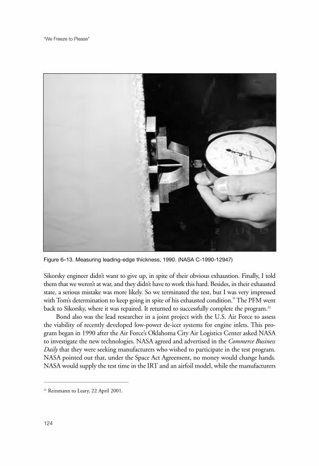
Sikorsky engineer didn’t want to give up, in spite of their obvious exhaustion. Finally, I toldthem that we weren’t at war, and they didn’t have to work this hard. Besides, in their exhaustedstate, a serious mistake was more likely. So we terminated the test, but I was very impressedwith Tom’s determination to keep going in spite of his exhausted condition.” The PFM wentback to Sikorsky, where it was repaired. It returned to successfully complete the program.24
Bond also was the lead researcher in a joint project with the U.S. Air Force to assessthe viability of recently developed low-power de-icer systems for engine inlets. This pro-gram began in 1990 after the Air Force’s Oklahoma City Air Logistics Center asked NASAto investigate the new technologies. NASA agreed and advertised in the Commerce BusinessDaily that they were seeking manufacturers who wished to participate in the test program.NASA pointed out that, under the Space Act Agreement, no money would change hands.NASA would supply the test time in the IRT and an airfoil model, while the manufacturers
“We Freeze to Please”
124
Figure 6–13. Measuring leading-edge thickness, 1990. (NASA C-1990-12947)
24 Reinmann to Leary, 22 April 2001.
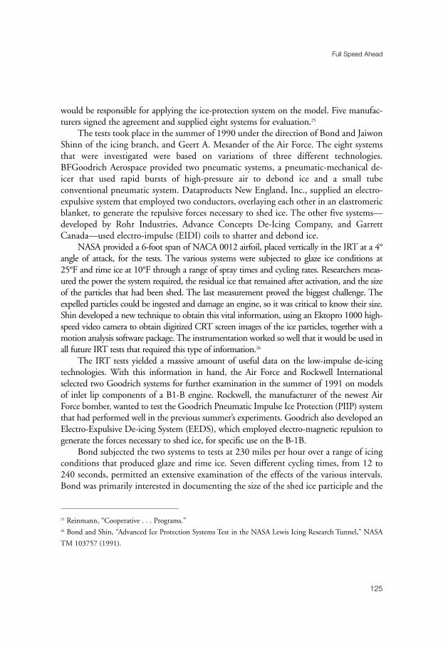
would be responsible for applying the ice-protection system on the model. Five manufac-turers signed the agreement and supplied eight systems for evaluation.25
The tests took place in the summer of 1990 under the direction of Bond and JaiwonShinn of the icing branch, and Geert A. Mesander of the Air Force. The eight systemsthat were investigated were based on variations of three different technologies.BFGoodrich Aerospace provided two pneumatic systems, a pneumatic-mechanical de-icer that used rapid bursts of high-pressure air to debond ice and a small tubeconventional pneumatic system. Dataproducts New England, Inc., supplied an electro-expulsive system that employed two conductors, overlaying each other in an elastromericblanket, to generate the repulsive forces necessary to shed ice. The other five systems—developed by Rohr Industries, Advance Concepts De-Icing Company, and GarrettCanada—used electro-impulse (EIDI) coils to shatter and debond ice.
NASA provided a 6-foot span of NACA 0012 airfoil, placed vertically in the IRT at a 4°angle of attack, for the tests. The various systems were subjected to glaze ice conditions at 25°F and rime ice at 10°F through a range of spray times and cycling rates. Researchers meas-ured the power the system required, the residual ice that remained after activation, and the sizeof the particles that had been shed. The last measurement proved the biggest challenge. Theexpelled particles could be ingested and damage an engine, so it was critical to know their size.Shin developed a new technique to obtain this vital information, using an Ektopro 1000 high-speed video camera to obtain digitized CRT screen images of the ice particles, together with amotion analysis software package. The instrumentation worked so well that it would be used inall future IRT tests that required this type of information.26
The IRT tests yielded a massive amount of useful data on the low-impulse de-icingtechnologies. With this information in hand, the Air Force and Rockwell Internationalselected two Goodrich systems for further examination in the summer of 1991 on modelsof inlet lip components of a B1-B engine. Rockwell, the manufacturer of the newest AirForce bomber, wanted to test the Goodrich Pneumatic Impulse Ice Protection (PIIP) systemthat had performed well in the previous summer’s experiments. Goodrich also developed anElectro-Expulsive De-icing System (EEDS), which employed electro-magnetic repulsion togenerate the forces necessary to shed ice, for specific use on the B-1B.
Bond subjected the two systems to tests at 230 miles per hour over a range of icingconditions that produced glaze and rime ice. Seven different cycling times, from 12 to240 seconds, permitted an extensive examination of the effects of the various intervals.Bond was primarily interested in documenting the size of the shed ice participle and the
Full Speed Ahead
125
25 Reinmann, “Cooperative . . . Programs.”26 Bond and Shin, “Advanced Ice Protection Systems Test in the NASA Lewis Icing Research Tunnel,” NASA
TM 103757 (1991).

distribution, texture, quantity, and thickness of the remaining ice. Data from the testsshowed that the PIIP system performed slightly better than the EEDS. However, neithersystem had been optimized for the complex geometry of the B-1B inlet. Bond concludedthat further tests would be necessary to determine the efficiency of the systems.27
Bond registered his satisfaction with the results of the two-year program with the AirForce. “The tests were the first of their kind in terms of placing identical constraints ona range of new ice-protection systems,” he emphasized. “As a result, an extensive databasefor residual ice, particle size, and input power and pressure information had been assem-bled. One of the outcomes of the tests has been the development of a set of testtechniques, including a methodology that allows the capture and analytical post-test pro-cessing of ice-shedding events.”28
“We Freeze to Please”
126
Figure 6–14. John Reinmann in the IRT control room, 1992. (NASA C-92-8515)
27 Bond and Shin, “Results of Low Power Deicer Tests on the Swept Inlet Component in the NASA Lewis Icing
Research Tunnel,” NASA TM 105968 (1993).28 Bond, “Low-Power Deicer Program,” NASA-Industry Workshop on Aircraft Icing, NASA Lewis Research
Center, 27–29 July 1993.
As Reinmann neared retirement in the early 1990s, he had the pleasure of witnessingthe IRT become an even more attractive research facility when its ability to simulate highspeeds was increased by over 25 percent. This unexpected improvement came in the wakeof the “Great Fan Blade Crisis” of the mid-1980s.
On 9 July 1985, the wooden fan blades in NASA’s 7 x 10-foot High-Speed WindTunnel at Langley suffered a catastrophic failure. To say that this caused great concern atNASA Headquarters would be an understatement. There were ten NASA tunnels thatused wooden fan blades, six at Langley, three at Ames, and the IRT. Committees toreview the condition of the fan blades were formed at all three centers, together with anational committee on structural integrity of wooden fan blades.
At Lewis, James H. Diedrich was appointed to head the local committee. Other mem-bers included Thomas O. Cressman for structural design and analysis; John L. Shannon,Jr. for fracture mechanics and fatigue; Kerry L. Remp for systems safety; and David A.Spera for wooden blade structures. The committee reviewed the history of the IRT blades.In operation since 1944, the fan system had not needed any major components replaced.The fan, 25.4 feet in diameter, consisted of twelve blades of Sitka spruce, each weighing250 pounds. At maximum revolutions per minute of 460 and a tip speed of 612 feet persecond, the fan produced an airspeed of 300 miles per hour without a model in the tunnel.Unlike the fan blades in NASA’s other tunnels, the IRT blades had been subject to icedamage. This damage, however, was easily repaired by use of a structural adhesive. The IRTblades also were attached to the hub by bolts and clamping. In the Langley tunnel thatexperienced the failure, the blades had been secured by bolts alone.
The Lewis review committee reported in December 1986 that the IRT fan bladeswere not in any danger of failing. The hub attachment system provided “high margins ofsafety against fatigue failure,” and no significant loss of structural integrity could beexpected in the next five to ten years of operation at the design speed of 460 revolutionsper minute. From the standpoint of fatigue life analysis, the committee concluded, theIRT blades were judged to have “an indefinite life” at 460 revolutions per minute.29
NASA Headquarters was not convinced and wanted to shut down the tunnel untilmetal fan blades were installed. Facility manager Zager countered that the Lewis reviewhad demonstrated that the wooden blades were perfectly safe and argued strongly againsta shutdown. Finally, upon the recommendation of the national wood fan blade com-mittee, Headquarters directed Lewis to purchase (for $200,000) and install a new set ofblades. After further discussions with the experts at Lewis, however, Headquartersallowed Zager to keep the original blades in operation and store the new blades. At the
Full Speed Ahead
127
29 Diedrich, et al., “Report of the NASA-LeRC Review Committee Regarding the Structural Integrity of the
Icing Research Wind Tunnel Fan,” 22 December 1986, History Office, GRC.

same time, Headquarters insisted that the fan blades in the IRT be inspected before andafter every test.30
The inspection dictat, Zager contends, contributed to an accident in the tunnel.Inspection of the fan blades was performed with the aid of a fiberglass ladder. Once, at shiftchange, the ladder was left in front of the blades and was destroyed when the fan was turnedon. Word soon reached Headquarters about a “major accident” in the tunnel. General BillieJ. McGarvey, in charge of all facilities, called Zager and wanted to know how long thetunnel would be shut down and how much repairs would cost. Zager told him that theLewis wood shop would repair the damage to the blades in three or four days—at no costto Headquarters. McGarvey could not have been more pleased. In the end, it took twoweeks for Headquarters to approve the repairs, which were done in four days.31
The fan blade study that had been done by the Diedrich committee yielded someunexpected results. Spera, who had assisted in the analysis that had certified the originalblades for continued use, had discovered during his calculations that there might be away to increase the efficiency of the fan. At 460 revolutions per minute, the fan used only2,800 of the motor’s 5,000-horsepower potential to produce a maximum test sectionvelocity of 300 miles per hour. Spera’s analysis showed that if the blades were re-machined with a 5° increase in pitch, the same 460 revolutions per minute wouldincrease test section velocity to 385 miles per hour.
In 1993, what Reinmann described as “Spera’s great idea” was brought about throughin-house work at Lewis. The new fan blades were taken out of storage and modified by theLewis model development and machining branch. Supports were added to the turningvanes in the diffusing sections of the tunnel. Spera’s calculations proved accurate, giving theIRT the higher range of speed that many customers had been requesting.32
Reinmann, who in 1988 received NASA’s Exceptional Service Medal for his man-agement of the aircraft icing program, retired in May 1994. Reflecting on the majoraccomplishments of his sixteen years as head of NASA’s icing research, he believed thathis association with the FAA’s Richard Adams on the testing of ground de-icing fluidshad contributed significantly to the resolution of an important safety issue. Reinmannalso pointed to his support of the flight testing, the modernization of the IRT, the devel-opment of cooperative programs with industry, and a grant program to universities thatresulted in the training of engineers for icing research, many of whom were subsequently
“We Freeze to Please”
128
30 Zager interview.31 Ibid.32 David Sheldon, “Work Plan: Blade Pitch Modification to the Icing Research Tunnel Drive Fan,” 24 February
1993, History Office, GRC.
hired by private companies. In addition, Reinmann had fostered cooperation amongresearchers, facilitating the exchange of ideas.
One area stood out. During his sixteen years in the icing branch, Reinmann hadseen NASA become a key member of an emerging icing community. Together with hisdeputy, Shaw, he had worked closely with the icing committees in SAE, AIAA, andNATO’s Advisory Group for Aerospace Research & Development (AGARD). NASAresearchers had served on these committees, presented papers at meetings, and promotedthe exchange of information and ideas about developments in icing. Lewis had hosted anumber of symposiums and workshops that brought together individuals from privatecompanies and government agencies, both in the United States and abroad, who shareda common interest in icing. Reinmann, of course, had not been alone in these efforts.Adams of the FAA, for example, vigorously had promoted the same objectives.Nonetheless, NASA had been a powerful moving force in creating a close-knit group ofthe icing experts that formed the heart of the icing community.33
Clearly, NASA’s icing research program had come a long way since 1978. Comparedto the propulsion programs at the Lewis laboratory, it remained modestly funded andmanned. “I think management tolerated it,” Reinmann recalled, “because it producedthe type of publicity that the public and Headquarters could understand—flight safety.And the IRT’s uniqueness and its heavy usage by industry added to [Lewis’s] value whenCongress was looking to eliminate some of the NASA centers.” Indeed, by the time ofReinmann’s retirement, the IRT was being used more than a thousand hours a year, onaverage. “That high usage rate,” Reinmann emphasized, “says a lot for our tunnel oper-ators, our operations engineers, and our research engineers.” Important work had beendone in developing advanced ice-protection systems and in formulating computer codesto predict the response of any aircraft to an icing encounter. Much had been accom-plished under Reinmann’s leadership, but new challenges lay ahead.34
Full Speed Ahead
129
33 Reinmann interview.34 Interview with Reinmann in Lewis News, 26 March 1993; Reinmann to Leary, 12 April 2001.

131
Chapter 7
New Challenges
While the major icing safety issue of the 1980s had centered on the ground de-icingproblems of large transports, the 1990s saw the focus shift to inflight icing difficultiesthat were encountered by the smaller airplanes of the booming commuter aviationindustry. The Airline Deregulation Act of 1978 had provided the legal foundations for asharp rise in short-haul traffic between large metropolitan areas. This had been followedby “code-sharing” agreements in the mid-1980s, under which commuter carriers acted as“feeders” for major airlines. As a result, passengers carried by the commuters had risenfrom 11 million in 1978 to 38 million in 1990.1
American Eagle, a feeder for American Airlines, had emerged during the 1980s asone of the larger commuters. Starting out in 1979 as Simmons Airlines, a small com-muter based in Marquette, Michigan, the company had concluded a code-sharingagreement with American Airlines in April 1986 and had begun flying as AmericanEagle. Two years later, Simmons was purchased by the parent company of AmericanAirlines. By the early 1990s, American Eagle was a major airline in its own right, oper-ating a fleet of seventy-nine aircraft and flying to thirty cities from American Airlines’sChicago hub and thirty-one cities from the parent’s Dallas-Fort Worth hub.2
Prominent in American Eagle’s fleet were forty-seven aircraft that had been builtspecifically for the commuter market by Avions de Transport Regional (ATR). Formedin 1980 by Aerospatiale of France and Aeritalia of Italy to jointly develop regional air-liners, ATR had first produced the model 42 in 1984. The ATR 42 was a twin-engineturboprop, with a T-tail and high straight wing that carried forty-six passengers and crew.
1 On the rise of the commuter industry, see R. E. G. Davies and I. E. Quastler, Commuter Airlines of the United
States (Smithsonian Institution Press, 1995).2 “Aircraft Accident Report: In-Flight Icing Encounter and Loss of Control, Simmons Airlines, d.b.a. American
Eagle Flight 4184, Avions de Transport Regional (ATR) Model 72-212, 31 October 1996,” NTSB/AAR-96/01,
adopted 9 July 1996.
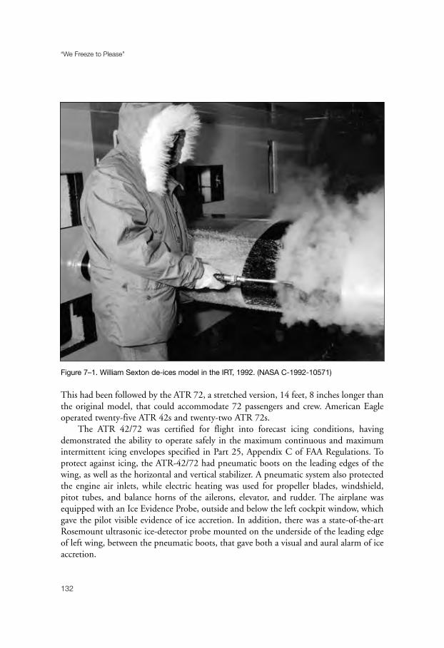
This had been followed by the ATR 72, a stretched version, 14 feet, 8 inches longer thanthe original model, that could accommodate 72 passengers and crew. American Eagleoperated twenty-five ATR 42s and twenty-two ATR 72s.
The ATR 42/72 was certified for flight into forecast icing conditions, havingdemonstrated the ability to operate safely in the maximum continuous and maximumintermittent icing envelopes specified in Part 25, Appendix C of FAA Regulations. Toprotect against icing, the ATR-42/72 had pneumatic boots on the leading edges of thewing, as well as the horizontal and vertical stabilizer. A pneumatic system also protectedthe engine air inlets, while electric heating was used for propeller blades, windshield,pitot tubes, and balance horns of the ailerons, elevator, and rudder. The airplane wasequipped with an Ice Evidence Probe, outside and below the left cockpit window, whichgave the pilot visible evidence of ice accretion. In addition, there was a state-of-the-artRosemount ultrasonic ice-detector probe mounted on the underside of the leading edgeof left wing, between the pneumatic boots, that gave both a visual and aural alarm of iceaccretion.
“We Freeze to Please”
132
Figure 7–1. William Sexton de-ices model in the IRT, 1992. (NASA C-1992-10571)

The ATR 42/72 ice-protection system was designed to be operated at three levels.Level I, which activated all probes and the windshield heating system, was turned on atall times. When a pilot encountered atmospheric conditions that were conducive toicing, he went to Level II, which turned on the engine intake boots and the electricalsystem for propellers and aileron/elevator/rudder horns. At the first visual indication oficing, the pilot went to Level III and activated the pneumatic boots for the wings andhorizontal and vertical stabilizers.
On 31 October 1994, American Eagle Flight 4184 departed Chicago’s O’HareAirport on schedule at 11:39 A.M. for a round-trip flight to Indianapolis. The ATR 72reached its destination without incident. The flight left Indianapolis at 2:55 P.M. for the45-minute return to Chicago—the pilot having been informed that icing might beencountered en route. At 3:13 P.M., Captain Orlando Aguiar received clearance for hisapproach into Chicago and began to descend from 16,000 feet to 10,000 feet. Duringthe descent, he activated the Level III ice-protection system.
Upon reaching 10,000 feet, Chicago Approach Control directed flight 4184 to entera holding pattern, 18 miles south of the Chicago Heights VOR. As the airplane wentaround in its racetrack holding pattern, everything seemed normal. A flight attendantvisited the cockpit and discussed “both flight and non-flight-related information with thepilots.” At 3:30 P.M., Captain Aguiar remarked to first officer Jeffrey Gagliano, “we’re justwallowing in the air right now.” Three minutes later, Aguiar set the flaps to the 15° posi-tion, but icing did not seem to be a major concern. “That’s much nicer, flaps fifteen,”Gagliano commented to Aguiar. At 3:49 P.M., Aguiar departed the cockpit and went aftto use the restroom. When he returned, Gagliano remarked, “we still got ice.”
At 3:56 P.M., flight 4184 was cleared to descend to 8,000 feet and to expect clear-ance into Chicago in 10 minutes. As the aircraft approached 9,000 feet, it commencedto roll rapidly to the right, and the autopilot disconnected. The cockpit voice recorderpicked up “brief expletive remarks,” followed by “intermittent heavy breathing.” At 77°right wing down, the ATR 72 started to roll left toward wings level, then right again ata rate in excess of 50° per second. Captain Aguiar’s control column force exceeded 22pounds as the airplane made a complete roll through an inverted position to wings level.The ATR 72 then began another roll excursion to the left. At this point, the airspeed reg-istered 300 knots with 73° nose down, as both pilots pulled on the control column.
As the airplane reached 1,700 feet, the “Whoop! Whoop!” of the ground proximitywarning system sounded. First officer Gagliano made “an expletive comment” as the air-speed increased to 375 knots, 38° nose down. The crew continued to fight for control ofthe aircraft until the ATR 72 crashed into a wet soybean field near Roselawn, Indiana, at3:59 P.M. The two pilots, two flight attendants, and all 64 passengers died instantly.
New Challenges
133
On 8 November 1994, the National Transportation Safety Board (NTSB) contactedthe icing branch at Lewis and asked for technical support in its investigation of theRoselawn tragedy. The NTSB was especially interested in obtaining information on iceaccretion, ice-protection systems, and data on iced airplane stability and control. NASAresponded to assigning researchers Jaiwon Shin and Thomas P. Ratvasky to the NTSB’sAirplane Performance Group.3
Shin and Ratvasky traveled with the group to Toulouse, France, on 12 November.For a week, the group met with the ATR engineering staff to review icing certificationdocuments and test procedures, and to discuss previous roll-control anomalies due toicing. Shortly after Shin and Ratvasky returned to the United States in early December,the NTSB asked NASA to conduct tests in the IRT of an MS-317 airfoil, which had asimilar cross-section profile to the outboard portion of an ATR 72 wing. The tests, con-ducted on 8–10 and 12–14 December, showed that large super-cooled water droplets,which had been detected in the vicinity of the Roselawn accident, could accrete beyondthe area that was protected by pneumatic boots. Even before the tests were completed,the FAA had sufficient concern about the problem to prohibit ATR 42/72s from flyingin “known or forecast” icing conditions.
While NASA developed a program to look more carefully in the phenomenon oflarge droplet icing, an FAA special certification review team arranged with the U.S. AirForce to use their KC-135 spray tanker for flight tests with an ATR 72. Again, the Boardrequested the technical assistance of the icing section. This time, Richard Ranaudo, anexperienced Twin Otter research pilot, accompanied Ratvasky to Edwards Air Force Base,California, the site of the tests.
The tanker flights began on 14 December. Ranaudo’s experience soon proved valu-able to the test team. For example, he suggested using tufts on the upper surface of theATR 72 wing to help detect flow separation. At the same time, Ratvasky held discussionswith Air Force personnel about icing cloud characteristics and measuring techniques.
The tanker tests demonstrated that in large droplet conditions with flaps at 15°, a ridgeof ice could form at the 9 percent chord position of the ATR 72’s wings, whereas the air-craft’s pneumatic boots covered only to the 7 percent chord. This problem no doubt causedthe uncommanded roll event at Roselawn. On 11 January 1995, the FAA withdrew itsblanket prohibition against flight into icing conditions for the ATR 42/72, pending the fit-ting of new pneumatic boots to cover a larger wing area and new training for pilots.
The Roselawn investigation marked the beginning of a major program at Lewis tostudy the icing conditions found in freezing drizzle and freezing rain, collectively known
“We Freeze to Please”
134
3 Icing Technology Branch to the director of aeronautics, “Summary of NASA LeRC Involvement in the ATR-72
Accident in Roselawn, IN,” 5 January 1995. The author is indebted to Mr. Ratvasky for a copy of this document.
as super-cooled large droplet (SLD) icing. Up to this point, the goal of the IRTresearchers had been to simulate the natural icing conditions that had been defined bythe flight research of the late 1940s. These conditions, as noted earlier, had been incor-porated into Appendix C of FAR Part 25 and set the parameters that aircraft had to dealwith to be certified for flight into forecast icing conditions. One component of the icingenvironment was droplet size. The great majority of icing involved drops with a meaneffective diameter of 15 to 50 microns. The early challenge for the nozzle designers of theIRT had been to produce these small diameter droplets.4
Icing conditions, of course, had always existed in nature beyond the Appendix Cenvelope. The FAA, however, assumed that the probability of aircraft flying into theseextreme conditions was one in a thousand. Even before the Roselawn accident, questionshad been raised about the continued acceptability of the Appendix C standards. Theappearance of a new generation of turboprop airliners in the 1980s made these questionsmore urgent, as their advanced, highly efficient wings were less tolerant of icing than pre-vious airfoils. Even a small amount of ice could make these turboprops difficult tocontrol—without the warning signs that pilots had come to expect.5
NTSB investigators estimated that the American Eagle ATR 72 had flown intosuper-cooled water droplets in the size range of 100 to 400 microns. These conditions,FAA safety engineer John P. Dow, Sr., pointed out, “may challenge contemporary under-standing of the hazards of icing.” While the FAA launched its own program to study thesafety and certification implications of SLD icing, NASA researchers Harold E. Addy, Jr.,and Dean R. Miller, together with Robert F. Ide of the Army Research Laboratories,began a series of experiments in the IRT to determine the effect of SLD ice accretion onTwin Otter and NACA 23012 wing sections.6
New Challenges
135
4 Whereas Appendix C used “mean effective droplet diameter” (MED) as a standard of measurement, researchers
in the 1990s with their superior measurement tools used “median volumetric diameter” (MVD). Both MED and
MVD divided total water volume present in the droplet distribution in half, with half the water volume in larger
drops and half in smaller drops, but MED was based on assumed droplet distribution while MVD measured
actual droplet size.5 For the problems facing pilots, see Jan W. Steenblik, “Inflight Icing: Certification vs. Reality . . . Where the
Difference Can Mean Life or Death.” This article first appeared in Air Line Pilot in August 1995 and was reprinted
in Flight Safety Foundation, “Protection Against Icing: A Comprehensive Overview,” a special issue of Flight
Safety Digest (June–September 1997), pp. 154–60.6 For Dow’s remarks and the FAA’s program, see “Proceedings of the FAA International Conference on Aircraft
Inflight Icing,” DOT/FAA/AR-96/81,l (August 1996), vol. I, pp. 7–11. NASA’s program is detailed in HaeOk
Skarda Lee, “NASA’s Aircraft Icing Research in Supercooled Large Droplet Conditions,” in ibid., pp. 83–100.

“We Freeze to Please”
136
Figure 7–2. Technician Dan Gideon with AH-64 (Apache) Longbow fire control radar during icing
tests, 1993. (NASA C-1993-4831)

Using a droplet size of 160 microns, Ide, who was responsible for calibrating thetunnel’s icing cloud for droplet size, liquid water content, and cloud uniformity, ran aspecial series of calibration tests. Although he did not have time to calibrate the 160-micron-diameter cloud at various liquid water contents for given airspeeds, he wassatisfied that the tunnel simulation would produce accurate results.7
The first series of experiments employed a Twin Otter wing section. Researcherssubjected the aluminum airfoil with a constant chord of 77.25 inches to an array of largedroplet icing conditions, including variations in temperature, airspeed, droplet size, angleof attack, pneumatic boot cycle interval, and flap settings. They found that an ice ridgeformed aft of the de-icer boot on every experimental icing run. The ridge was sensitiveto changes in temperature, reaching a maximum size at 28°F for 125 miles per hour and30°F for 195 miles per hour. Variations in boot cycling time did not have a significanteffect on the residual ice accretion.
A second series of IRT tests were performed on a NACA 23012 wing section. Thistapered airfoil was mounted vertically in the test section and had a chord length whichvaried from 73.8 inches at the floor to 65.2 inches at the ceiling. Technicians outfittedthe leading edge of the model with a full-span pneumatic de-icer boot that extended to6 percent of the chord on the suction surface and to 11 percent on the pressure surfaceof the airfoil.
Researchers Addy and Miller selected the following “anchor points” for the tests: 32°F,160 microns, 0.82 grams per cubic meter LWC, 195 miles per hour, 0° angle of attack,3 minutes boot cycle, and 18 minutes spraying time. They then investigated the effectsof each one of the anchor points while holding the other points steady. For example,what would be the effect on the airfoil of lowering the temperature to 28°F while allother conditions remained unchanged for the anchor points?
As in the previous Twin Otter study, researchers discovered that temperature had themost significant impact on ice accretion. While holding the other parameters constant attheir anchor points, the researchers ran tests at temperature ranges of 5°F to 37°F. At37°F, all impinging water ran back to the trailing edge and was blown off the airfoil. Icebegan to form at 34°F, with a distinct ridge just aft of the active portion of the boots onboth suction and pressure surfaces. At temperatures below 30°F, the ridge appeared toharden and become more resistant to shedding. The largest ice ridge—over 1 inch inheight—occurred in temperature ranges of 24°F through 28°F.
Tests on the Twin Otter and NACA 23012 airfoils, the researchers concluded,yielded “valuable information, as well as a substantial database on large droplet ice accre-
New Challenges
137
7 Harold E. Addy, Jr., Dean R. Miller, and Robert F. Ide, “A Study of Large Droplet Ice Accretion in the NASA
Lewis IRT at Near Freezing Conditions; Part 2,” NASA TM 107424 (1996).

tions.” Nonetheless, there remained a great deal of work to be done. The next phase ofresearch into the phenomenon of SLD icing, they believed, should be “a fairly rigorousflight program.” Because so little data was available to characterize naturally occurringlarge droplet icing conditions, flight tests were necessary “to generate a realistic largedroplet cloud envelope for the IRT and to help define tests to investigate the effects ofvarying LWC on large droplet ice accretions.”
Following the IRT tests, NASA and the FAA agreed to co-sponsor a three-year pro-gram of flight research to develop a database to document atmospheric large dropleticing, improve weather forecasting tools, extend icing simulation capabilities of the IRTand LEWICE, and provide educational information to pilots to help them deal withlarge droplet icing encounters. Joining NASA and the FAA in this program was theNational Center for Atmospheric Research (NCAR), which would provide weather fore-casts and inflight guidance. In addition, Atmospheric Environmental Services, RoboticVision Systems Incorporated, and BFGoodrich Aerospace provided special equipmentfor NASA’s Twin Otter.8
Target areas for the research program would be the Great Lakes region. Not only didthis location have conditions that were conducive to large droplet icing, but it also wasseeing an increasing number of commuter flights. NCAR scientists examined meteoro-logical data for the Cleveland area for the years 1961 to 1990 and concluded that thehighest probability for encountering SLD conditions occurred during the months ofDecember through March.
NASA conducted research flights in 1997 between 13 January and 5 February, andbetween 6 March and 3 April. In all, twenty-nine flights took place. Four flights wereconducted in clear air in order to establish an ice-free baseline. Most of the flights intoicing encountered a mixture of small and large droplets. Three flights, however, weremade in prolonged large droplet conditions.
A typical mission for this program began with preflight checks of the aircraft andinstrumentation at 6 A.M. This was followed by a weather briefing from NCAR at 7 A.M.Forecasters used a variety of information in an attempt to locate icing areas. Infraredsatellite imagery determined cloud locations, cloud top temperature, cloud top altitude,and the likelihood of liquid water versus ice crystals, while radar identified areas of pre-cipitation. Forecasters also had surface observations, surface and upper air charts, andpilot reports. They integrated this information to identify large droplet and other icingareas, then suggested a flight location, strategy for sampling the clouds, and an escape
“We Freeze to Please”
138
8 Dean Miller, Thomas Ratvasky, Ben Bernstein, Frank McDonough, and J. Walter Strapp, “NASA/FAA/NCAR
Supercooled Large Droplet Icing Flight Research: Summary of Winter 96–97 Flight Operations,” NASA TM
206620 (1998).
route. Researchers were especially impressed with the forecasting talents of meteorologistBen C. Bernstein. “Ben’s knowledge and skill,” Ratvasky has emphasized, “were the mainreasons we were able to get into SLD.” After discussing the proposed flight plan withNCAR, the flight crew would prepare for a takeoff between 8 and 9 A.M.
Climbing out of Cleveland, the Twin Otter would head toward the target area at analtitude prescribed in the weather briefing. While en route, the crew would be in contactwith NCAR meteorologists via a satellite communications link to discuss the most recentinformation. When the aircraft reached the area of forecast large droplet icing, the crewwould attempt to perform a “sounding” of the cloud. They wanted to know the cloud topand base, as well as the altitudes of the freezing level, liquid water, and large droplet icing.
With the sounding completed, the aircraft entered the icing cloud at which it wasmost likely to find SLD conditions. Researchers would then sample the cloud during aseries of horizontal transects. At some point, the crew would decide to exit the cloud todocument icing accretion with a stereo photographic system and to test its effect on air-craft performance.
At the conclusion of the flight, a debriefing session would be held with NASA’spilots, operations staff, researchers, and NCAR meteorologists. Participants would reviewhow the flight had been conducted, identify areas for improvement, and discuss instru-mentation problems. Researcher Dean Miller would then analyze the cloud physicsdata—droplet spectra, liquid water content, temperature—and send the results to theFAA’s Technical Center, where Richard K. Jeck was reviewing Appendix C criteria inorder to expand the icing certification envelope to include SLD conditions.
The second phase of the flight research program, which took place betweenNovember 1997 and March 1998, turned out to be the most successful icing season ofthe three-year program. Researchers made a total of fifty-four flights, encountering icingconditions during twenty-eight of eighty-three flight hours. The high point of the pro-gram occurred on 4 February 1998, when the Twin Otter experienced a prolongedexposure to freezing rain. Whereas most SLD icing had focused on freezing drizzle, littlewas known about the effects of larger droplet freezing rain on aircraft performance. Inone previous encounter with the phenomena by a research aircraft, ice accretion hadadhered smoothly to the airfoil surface and had not caused any significant degradationof performance. It was a far different story, however, for the SLD researchers.
While flying in the vicinity of Parkersburg, West Virginia, the Twin Otter had a 90-minute exposure to freezing rain, during which droplet sizes exceeded 1,000 microns. Evenwith de-icing equipment turned to “auto-fast,” in which the boots cycled every 60 seconds,clear ice remained on and aft of the boots, while ice ridges built up on the wings and tail.Climbing out of the cloud deck, the Twin Otter conducted three performance sweeps.They showed that maximum airspeed had declined from a clear airspeed of 150 knots to115 knots, while buffet speed went from 68 knots to 90 knots. While the flight envelope
New Challenges
139

“We Freeze to Please”
140
Figure 7–3. IRT renovation, 1993. (NASA C-93-7170)

decreased by 70 percent, coefficients of drag increased by 60 to 200 percent (depending onangle of attack), and maximum coefficient of lift was reduced by 30 percent.
“This case study,” the report of the flight emphasized, “clearly demonstrates thatexposure to classical FZRA [freezing rain] can cause significant ice to accrete on the TwinOtter airframe, including ice ridges and nodules on unprotected surfaces.” Subsequentperformance tests revealed “a dramatic increase in aircraft drag and decrease in lift thatdecreased the size of the Twin Otter’s safe operating window.” Freezing rain, theresearchers concluded, “can pose a significant flight icing hazard and should not beignored when considering SLD issues.”9
The third year of flight research proved anticlimactic. The program started late, inFebruary 1999, due to a Headquarters-mandated safety inspection in January, and itlasted only until March. A total of twelve flights were conducted with 15 flight hours.Instrument problems plagued most missions, and little useful data was obtained.Whereas Miller had been able to send 828 data points to Jeck during the previous twophases of the SLD flight program, he was unable to pass along any useful data from thefinal effort.10
Overall, the SLD flight program was an outstanding success. Thanks to the effortsof researchers, pilots, NCAR meteorologists, electrical engineers, avionics technicians,and fabrication, imaging, and data-processing specialists, a great deal had been learnedabout SLD icing conditions. At the FAA’s Technical Center, Jeck took the data from theNASA flights, along with information from the Meteorological Service of Canada andother sources, to produce a combined set of SLD data for review by the Ice ProtectionHarmonization Working Group (IPHWG), an international body that was chartered bythe FAA’s Aviation Rulemaking Advisory Committee. “The IPHWG is still working withthe issue of SLD icing conditions in the certification process,” Ratvasky noted in May2001, “but the data that has been provided by NASA and MSC has enabled the policy-makers to make decisions based on solid research.”11
Tailplane icing ranked with large droplet icing as the most notable icing safety issueof the 1990s. The problem, itself, like SLD icing, was not entirely new. For example,undetected ice on the horizontal stabilizer of a Continental Airlines Vickers Viscount810 had caused the airplane to pitch down during an attempted night landing in freezingprecipitation at Kansas City on 29 January 1963. The aircraft had struck the groundshort of the runway, causing eight fatalities. The problem, however, became more urgent
New Challenges
141
9 Ben C. Bernstein, Thomas P. Ratvasky, Dean R. Miller, and Frank McDonough, “Freezing Rain as an In-Flight
Icing Hazard,” NASA TM-2000-210058 (June 2000).10 Ratvasky to Leary, 11 May 2001.11 Ibid.

with the appearance of the new generation of turboprop commuter airplanes in the1980s. These aircraft had advanced airfoils that were unforgiving when it came to icecontamination and featured non-powered reversible control surfaces and pneumatic bootde-icing systems. With their short-haul routes that were generally flown at lower alti-tudes, the commuters had a greater exposure to icing than long-haul jet transports. Thiscombination of factors made them vulnerable to tailplane icing.12
Research into the problem had first been undertaken during the late 1970s and early1980s by a Swedish-Soviet working group in the wake of the crash to a Linjeflyg VickersViscount on 15 January 1977, near Stockholm. Their wind tunnel and flight tests thatstudied the tailplane stall phenomenon had failed to produce definite results, but hadprovided insights that would assist later researchers. In the early 1990s, NASA had con-ducted a preliminary flight investigation into control anomalies that were caused bytailplane contamination. Researchers found that an ice casting placed on the Twin Otter’shorizontal tail had caused decreased longitudinal stability, a condition that had worsenedwhen flaps had been lowered 10° or more.13
To promote greater awareness of the problem, NASA and the FAA sponsored anInternational Tailplane Icing Workshop at Lewis in early November 1991 that wasattended by more than 100 representatives of industry and government from theUnited States and eight foreign countries. It soon became clear that the phenomenonof ice accretion on the horizontal tailplane of turboprop commuters was widespreadbut not well understood, especially in the United States, by either manufacturers oroperators. The Europeans seemed somewhat better acquainted with the problem. TheEuropean Joint Airworthiness Authority, for example, required manufacturers todemonstrate a specific pushover maneuver during certification for tailplane icing,whereas the FAA did not.
Captain Stephen Ormsbee of Henson Airlines, chairman of the Air Line PilotsAssociation’s Regional Airline Committee, pointed out that the chances of a turbopropflight crew experiencing tailplane icing were far greater than their chances of encounteringsevere wind shear. “We need to educate pilots about the hazards associated with tailplaneicing and provide them with a reliable means of detecting its presence,” he noted in thefinal report of the workshop. Also, he continued, “we need to require that turboprop air-planes demonstrate their ability to handle tailplane icing during certification.”14
“We Freeze to Please”
142
12 Porter J. Perkins and William J. Rieke, “Aircraft Icing Problems—After 50 Years,” a paper prepared for the 31st
Aerospace Sciences Meeting, Reno, NV, 11–14 January 1993; copy courtesy of Mr. Perkins.13 T. P. Ratvasky and R. J. Ranaudo, “Icing Effects on Aircraft Stability and Control Determined from Flight Data,
Preliminary Results,” NASA TM 105977 (1993).14 Ormsbee is quoted in Jan W. Steenblik, “Turboprop Tailplane Icing,” Air Line Pilot, January 1992, pp. 30–33.

Following a second workshop in April 1993, the FAA made a formal approach toNASA for assistance “to conduct research into the characteristics of ice-contaminatedtailplane stall (ICTS) and develop techniques or methodologies to minimize this hazard.”Tailplane icing, Thomas E. McSweeney, director of the FAA’s Aircraft CertificationServices, wrote to NASA, was “strongly suspected” as the cause of sixteen accidents duringthe past years that resulted in 139 fatalities. Most of these accidents had involved turbo-prop-powered transport and commuter aircraft, of which there were now 1,500 operatingin the United States. Because of the implications for flight safety, McSweeney proposedthat the FAA and NASA undertake a joint program to assure that the problems associatedwith tailplane icing were identified and corrected before an airplane entered service.15
The FAA’s request led to the signing of an interagency agreement under whichNASA’s Lewis Research Center and the FAA Technical Center at Atlantic City co-sponsored a Tailplane Icing Program (TIP). Thomas Ratvasky was given the task ofdrawing up a work plan for the program. He would prove an excellent choice for theassignment. A graduate of Case Western Reserve University in 1988, he had joinedNASA’s icing branch in 1990 after receiving his master’s degree in aeronautics fromGeorge Washington University. His first project had been a stability and control programto observe the effects of artificial ice shapes on the tail of the Twin Otter. Later researchhad involved flights into natural icing conditions. The TIP work would be a natural con-tinuation of these earlier research efforts.16
Early in 1994, representatives from Lewis, the FAA Technical Center, FAACertification Services, and Ohio State University met to discuss the work plan thatRatvasky had developed. They confirmed the NASA/FAA Tailplane Icing Program whichwould be funded by both agencies. Also, they endorsed Ratvasky’s proposal to enter into acooperative agreement between NASA and Ohio State University for dry air testing.Finally, they concurred on a four-year program that would involve both icing and dry airtunnel tests, followed by flight tests. Test facilities included the IRT, Ohio State’s Low-Speed Wind Tunnel, and NASA’s Twin Otter. Ratvasky would be the lead NASA researcher.Richard Ranaudo, a former U.S. Air Force fighter pilot who had joined NASA in 1974 andhad flown in the subsonic and supersonic engine test programs as well as in icing research,was designated as the lead pilot for the flight program. James T. Riley of the FAA TechnicalCenter would monitor the program and lend his expertise where needed.17
New Challenges
143
15 McSweeney to Wesley L. Harris, 21 April 1994; copy courtesy of Mr. Ratvasky.16 Interview with Thomas P. Ratvasky by William M. Leary, 22 September 2000.17 Ratvasky, “NASA/FAA Tailplane Icing Program Work Plan,” 8 April 1994, revised 1 May 1995; copy cour-
tesy of Mr. Ratvasky. Ratvasky presented this plan at the third FAA-sponsored International Tailplane Icing
Workshop, held in Toulouse, France, September 1994.
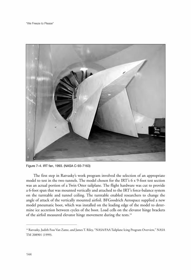
The first step in Ratvasky’s work program involved the selection of an appropriatemodel to test in the two tunnels. The model chosen for the IRT’s 6 x 9-foot test sectionwas an actual portion of a Twin Otter tailplane. The flight hardware was cut to providea 6-foot span that was mounted vertically and attached to the IRT’s force-balance systemon the turntable and tunnel ceiling. The turntable enabled researchers to change theangle of attack of the vertically mounted airfoil. BFGoodrich Aerospace supplied a newmodel pneumatic boot, which was installed on the leading edge of the model to deter-mine ice accretion between cycles of the boot. Load cells on the elevator hinge bracketsof the airfoil measured elevator hinge movement during the tests.18
“We Freeze to Please”
144
Figure 7–4. IRT fan, 1993. (NASA C-93-7163)
18 Ratvasky, Judith Foss Van Zante, and James T. Riley, “NASA/FAA Tailplane Icing Program Overview,” NASA
TM 208901 (1999).

A different model was developed for Ohio State’s 7 x 10-foot tunnel. Model makersused machinable plastic (Ren Shape) to construct a 2-D airfoil with a 4.75-foot chordand 7-foot span. It was intended to replicate the two-section geometry of the Twin Otterand included an elevator that could be set at various angles.
Ratvasky next turned to selecting accurate ice shapes for testing. He wanted to beginin the IRT, but the NASA facility was so heavily scheduled that he decided to use OhioState’s tunnel for the initial aero-performance tests. One ice shape to be attached to themodel had been developed from one of NASA’s icing flights in 1984. Another wasderived from LEWICE predictions. The two shapes were machined from Ren Shape,then sanded smooth and painted.
Initial tests at Ohio State began in September 1994. Data on the model was firsttaken without ice shapes in order to establish a baseline. The two ice shapes were thenattached to the airfoil, and measurements were made at various airspeeds, elevatorangles, and angles of attack. Just as the Ohio State tests concluded, the American Eagleaccident at Roselawn occurred, focusing attention on the more urgent problem of largedroplet icing. As noted earlier, Ratvasky joined the NTSB team that investigated theATR 72 accident.
Ratvasky was not able to turn his attention to the Tailplane Icing Program until thefall of 1995. The next phase of the program involved flight tests to establish a baselineagainst which to measure the effects of tailplane contamination. In September andOctober, the Twin Otter made seventeen flights. While pilots Ranaudo and DennisO’Donoghue confirmed the operation of the airplane’s hydraulic system during low-gravity maneuvers, Ratvasky measured tail-flow conditions and elevator settings forcruise, hold, and approach, as these conditions would be simulated in impending IRTtests. They determined the range of tailplane inflow angles for the flap, speed, thrust, andnormal accelerations to be tested with ice shapes.
Ratvasky was able to conduct TIP tests in the IRT in February 1996. The TwinOtter airfoil was subjected to a variety of icing cloud conditions, while different air-speeds, angles of attack, and elevator deflections simulated the cruise, holding, andapproach phases of flight. Following each test run, technicians made ice tracings andtook photographs of the resultant ice shapes. At the end of the night, they made a moldof a 15-inch span of the final ice accretion. Skilled craftsmen in the model shop thenextracted multiple polyurethane castings from the mold to have a full-span ice accretionfor later aero-performance tests in the Ohio State tunnel in August 1996.
Finally, everything was ready for flight tests with the various ice shapes that had beendeveloped in the IRT and Ohio State tunnel. The climax of the test program camebetween July and September 1997. Researchers Ratvasky and Judith Foss Van Zante tookdata as pilots Ranaudo, Robert McKnight, and William Rieke searched for the bound-aries of tailplane stalls with various ice shapes. On 17 September, Ranaudo passed the
New Challenges
145

boundary. The Twin Otter experienced a full tail stall, pitched nose down, and lost 300feet before Ranaudo recovered control, despite immediate corrective action.
A dozen flight tests with three ice shapes revealed that the paths to tailplane stallincreased with ice shape severity, flap deflection, airspeed, and thrust. Tactile clues thatpreceded stall events were difficulty (or inability) to trim the airplane, pitch excursions,and a buffeting of the controls. To recover from the stall, the pilot had to reduce power,pull back on the yoke, and raise flaps.
Tail stall recovery procedure, researchers emphasized, was the opposite of a recoveryfrom a wing stall. Ever since the early days of flight, pilots had been taught that theproper way to recover from a stall was to push down on the yoke and add power. Buttailplane stall was different. In a wing stall, airflow separates from the upper surface ofthe airfoil; whereas, with a tailplane stall, the flow separates from the lower surface of thetail. “Because of these differences in the stalling mechanism and recovery procedures,”Ratvasky and his colleagues concluded, “it was determined that pilots should be madeaware of the clues that may occur prior to a tailplane stall.”19
NASA quickly set out to spread the word. In October 1997, the icing branch con-ducted a guest pilot workshop for fifteen pilots and engineers from the FAA, TransportCanada, Bombardier, Cessna, Raytheon, Airline Pilot, Aviation Week & SpaceTechnology, Commercial & Business Aviation, Flying Magazine, and Professional Pilot.Each pilot had the opportunity to fly the Twin Otter with a tailplane ice casting,together with a NASA safety pilot. The guest pilots experienced the handling qualitiesof an aircraft with an ice-contaminated tailplane and practiced the pushover maneuverused in icing certification flight tests.
“The guest pilot program,” Ratvasky emphasized, “is important for building goodrelationships with aircraft manufacturers that in turn allow NASA to provide themwith appropriate design tools. The program enables us to get the word out that NASALewis is performing relevant aviation safety programs that will impact the wholeindustry, ranging from the aircraft manufacturers that make the airplanes to the oper-ators who fly them.”20
The following year, the icing branch produced a 23-minute video on tailplane icingthat described why and how tailplane icing occurred, the warning signs of an imminentstall, and the proper recovery procedures. The dramatic highlight of the video came withcockpit film of Ranaudo’s full tailplane stall of September 1997. Widely distributed, thevideo received such an enthusiastic reception from the aviation community that NASA
“We Freeze to Please”
146
19 Ratvasky, Van Zante, and Alex Sim, “NASA/FAA Tailplane Icing Program: Flight Test Report,” NASA TP
209908.20 Lewis News, December 1997.
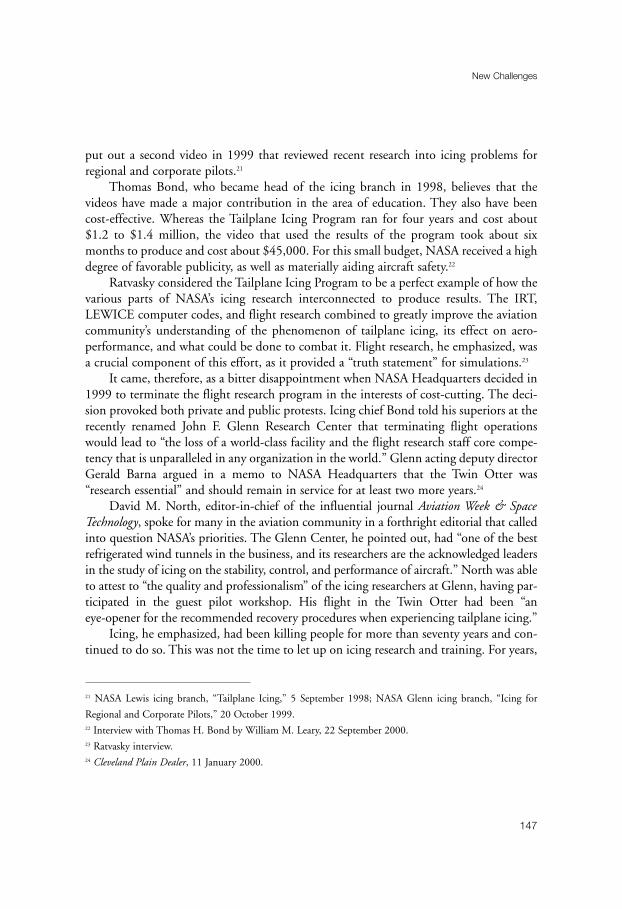
put out a second video in 1999 that reviewed recent research into icing problems forregional and corporate pilots.21
Thomas Bond, who became head of the icing branch in 1998, believes that thevideos have made a major contribution in the area of education. They also have beencost-effective. Whereas the Tailplane Icing Program ran for four years and cost about$1.2 to $1.4 million, the video that used the results of the program took about sixmonths to produce and cost about $45,000. For this small budget, NASA received a highdegree of favorable publicity, as well as materially aiding aircraft safety.22
Ratvasky considered the Tailplane Icing Program to be a perfect example of how thevarious parts of NASA’s icing research interconnected to produce results. The IRT,LEWICE computer codes, and flight research combined to greatly improve the aviationcommunity’s understanding of the phenomenon of tailplane icing, its effect on aero-performance, and what could be done to combat it. Flight research, he emphasized, wasa crucial component of this effort, as it provided a “truth statement” for simulations.23
It came, therefore, as a bitter disappointment when NASA Headquarters decided in1999 to terminate the flight research program in the interests of cost-cutting. The deci-sion provoked both private and public protests. Icing chief Bond told his superiors at therecently renamed John F. Glenn Research Center that terminating flight operationswould lead to “the loss of a world-class facility and the flight research staff core compe-tency that is unparalleled in any organization in the world.” Glenn acting deputy directorGerald Barna argued in a memo to NASA Headquarters that the Twin Otter was“research essential” and should remain in service for at least two more years.24
David M. North, editor-in-chief of the influential journal Aviation Week & SpaceTechnology, spoke for many in the aviation community in a forthright editorial that calledinto question NASA’s priorities. The Glenn Center, he pointed out, had “one of the bestrefrigerated wind tunnels in the business, and its researchers are the acknowledged leadersin the study of icing on the stability, control, and performance of aircraft.” North was ableto attest to “the quality and professionalism” of the icing researchers at Glenn, having par-ticipated in the guest pilot workshop. His flight in the Twin Otter had been “aneye-opener for the recommended recovery procedures when experiencing tailplane icing.”
Icing, he emphasized, had been killing people for more than seventy years and con-tinued to do so. This was not the time to let up on icing research and training. For years,
New Challenges
147
21 NASA Lewis icing branch, “Tailplane Icing,” 5 September 1998; NASA Glenn icing branch, “Icing for
Regional and Corporate Pilots,” 20 October 1999.22 Interview with Thomas H. Bond by William M. Leary, 22 September 2000.23 Ratvasky interview.24 Cleveland Plain Dealer, 11 January 2000.

NASA had shortchanged research and development in aeronautics in favor of the spaceprogram. “While the International Space Station and Mars research may be glitzy andglamorous,” he wrote, “NASA should not abandon an established effort that has savedlives and promises to save many more.” If NASA could spend billions of dollars on theInternational Space Station, then surely the agency could spare the $300,000 that ithoped to save by terminating the flight research program.25
In January 2000, NASA’s Office of Inspector General announced that it wouldreview the decision to end flight research. The ultimate fate of the program remained tobe seen as NASA’s icing research faced the challenges of a new millennium.26
“We Freeze to Please”
148
25 David M. North, “Reinstate NASA Icing Research,” Aviation Week & Space Technology, 152 (31 January
2000): 68.26 Cleveland Plain Dealer, 29 January 2000.

149
Chapter 8
The 1990s
The icing branch underwent a number of senior personnel changes during the1990s. Following Reinmann’s retirement in 1994, there were a series of acting branchchiefs for some nine months before Hao Ok Lee took over the job in 1995. Two yearslater, after Lee moved to a more senior position in the Lewis Base Program Office,Thomas Bond became acting chief, then permanent head of the branch in 1998. A one-time airplane mechanic on Twin Otters in Alaska, Bond received his B.S. in mechanicalengineering from Penn State in 1983. He joined NASA upon graduation and startedwork in the internal combustion engine section. In 1986 Bond moved to the icingbranch, where he gained a reputation as a “hands-on” individual who enjoyed experi-mental work.1
IRT facility managers also changed, beginning with Harold Zager’s retirement in1988. Several months before Zager left NASA, David W. Vincent was brought in to relievehim of responsibility for the IRT. A graduate of the University of West Virginia in 1963with a degree in aeronautical engineering, Vincent had worked in a variety of assignmentsduring his twenty-five-year career at NASA-Lewis, but he had limited tunnel managementexperience. “Not knowing anything about Dave,” Reinmann recalled, “we were a bit con-cerned when he was assigned to the IRT.” Reinmann’s apprehension soon vanished,however. Although just as committed as Zager to maximum productivity for the tunnel,Vincent’s style of management was less confrontational than his predecessors. With respectto scheduling, for example, Vincent adopted a cooperative approach, with weekly meetingsto review and adjust time allocations. Also, he had not been instructed, as had Zager, tomake contractors “happy.” On the contrary, there was a new emphasis on having manu-facturers pay for tunnel time except when they agreed to share data or participate in a jointprogram with NASA researchers. Vincent would not allow contractors to have additionaltime in the tunnel to complete experiments, although he would expand daily tunnel oper-
1 Bond interview; Reinmann interview.
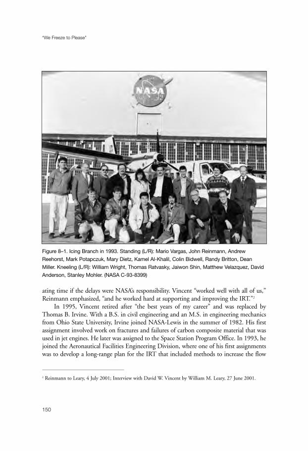
ating time if the delays were NASA’s responsibility. Vincent “worked well with all of us,”Reinmann emphasized, “and he worked hard at supporting and improving the IRT.”2
In 1995, Vincent retired after “the best years of my career” and was replaced byThomas B. Irvine. With a B.S. in civil engineering and an M.S. in engineering mechanicsfrom Ohio State University, Irvine joined NASA-Lewis in the summer of 1982. His firstassignment involved work on fractures and failures of carbon composite material that wasused in jet engines. He later was assigned to the Space Station Program Office. In 1993, hejoined the Aeronautical Facilities Engineering Division, where one of his first assignmentswas to develop a long-range plan for the IRT that included methods to increase the flow
“We Freeze to Please”
150
Figure 8–1. Icing Branch in 1993. Standing (L/R): Mario Vargas, John Reinmann, Andrew
Reehorst, Mark Potapczuk, Mary Dietz, Kamel Al-Khalil, Colin Bidwell, Randy Britton, Dean
Miller. Kneeling (L/R): William Wright, Thomas Ratvasky, Jaiwon Shin, Matthew Velazquez, David
Anderson, Stanley Mohler. (NASA C-93-8399)
2 Reinmann to Leary, 4 July 2001; Interview with David W. Vincent by William M. Leary, 27 June 2001.
quality in the test section and settling chamber, an upgrade to the spray system with the useof modern electronic control technology, and replacement of the aging heat exchanger.When Vincent retired, Irvine applied for and secured the position of IRT facility manager.
Irvine continued Vincent’s cooperative approach to the job. In part, this was aproduct of Irvine’s personality and management style. It was also the result of a changein NASA’s program management and funding stream that caused the need to create pro-gram offices separate from research organizations. In the icing world, this led to theestablishment of an ad hoc icing management team to determine overall program direc-tion. Team members included an aircraft icing program manager (first Jaiwon Shin, thenMary F. Wadel), the facility manager (Irvine), and the technology branch chief (Bond).Mark G. Potapczuk, as senior research engineer in the Icing Technology Branch, wouldbe brought in on an as-needed basis. This ad hoc arrangement, Irvine pointed out,worked extremely well, “primarily because of the individuals involved.”3
Irvine, like Vincent, thoroughly enjoyed his years with the IRT. Both men wereimpressed with the high esprit de corps among tunnel personnel. This was importantbecause facility managers, as Irvine soon learned, had management responsibility for thefacility—the “care and feeding” of the tunnel—but lacked direct responsibility for theresearchers, engineers, mechanics, technicians, and other individuals who worked in theIRT and reported to different branches at NASA. But it did not matter. Everyone workingin the tunnel, Irvine pointed out, had a sense that the IRT “was truly a national asset andthat their work was making an important contribution to aircraft safety.” When Irvine waspromoted in June 1999 to the position of chief of the Facility Management PlanningOffice, with responsibility for all the tunnels at Lewis/Glenn, he was replaced by Susan L.Kevdzija. A graduate of Ohio Northern University with an M.S. in industrial engineeringfrom Cleveland State University, Kevdzija joined NASA in 1990. Before taking over theIRT, she had held various engineering positions in space environmental testing, rocket andpropulsion testing, and space and aeronautical facility management.4
Essential to the operation of the IRT since the beginning, as Zager, Vincent, Irvine,and Kevdzija emphasized, was a talented and dedicated technical support staff. The careerof William P. Sexton can be seen in many ways as typical of this group, whose names rarelyfound their way into the reports generated by tunnel research. A Cleveland native, Sextongraduated from Brooklyn High School in 1960, then served two years in the Army. NASAemployed him in June 1963 as an apprentice mechanical technician. During his four yearsof apprenticeship, Sexton moved into different areas at Lewis about every six months. Healso attended evening classes for nine months a year that covered everything from safety to
The 1990s
151
3 Interview with Thomas B. Irvine by William M. Leary, 22 September 2000.4 Ibid.

physics. In 1979, he had his first tour in the IRT as a mechanical technician/tunnel oper-ator. He spent four years on this assignment, working under Raymond G. Sotos, and wasinvolved in all phases of tunnel operations, from maintenance to model buildup.
After a tour in the Zero-Gravity facility, Sexton returned to the IRT in 1988, one ofabout a dozen mechanical technicians, electronic technicians, and electricians who sup-ported tunnel operations. These were the people who maintained the aging spray barsand controls, patched ice-damaged fan blades, integrated models into the test section,and performed thousands of other tasks that made the work of the researchers possible.Because of individuals like Sexton, who brought to their job not only a pride in work-manship but also a deep affection for the tunnel, the IRT ranked as NASA’s mostproductive large-scale wind tunnel.5
“We Freeze to Please”
152
Figure 8–2. Lightning generator and radome in IRT, 1955. (NASA C-1995-4467)
5 Interview with William P. Sexton by William M. Leary, 18 June 2000.

The IRT was at the center of a wide range of icing investigations during the 1990s,most of which involved cooperative efforts with industry or government agencies. In1995, for example, NASA joined with the FAA in a program to document the ice shapesthat were occurring on airfoils on aircraft currently in service and to record the effects onaerodynamic performance. The database from the Modern Airfoils Program could beused for both airfoil design and in the development of icing simulation codes.
At the beginning of the program, NASA asked aircraft manufacturers to suggest air-foils sections to be used for the tests. Researchers at Lewis selected three designs—oneeach for commercial transports, business jets, and general aviation. The business jet andgeneral aviation airfoils approximated the airfoil sections found on the main wing, whilethe commercial airfoil section came from the horizontal tailplane. The Lewis model shopdesigned and fabricated three models for the IRT tests, each with a span of 6 feet and achord of 3 feet. Technicians fabricated the commercial transport and business jet modelsfrom fiberglass, and the general aviation model primarily from laminated mahogany.
Sexton and his associates mounted the models vertically in the test section of theIRT, attaching them to an external force balance on both top and bottom, with the lowerportion mounted on a turntable. The force balance was a three-component system thatmeasured lift, drag, and pitching moment. The airfoils were then subjected to icing con-ditions for short (2 minutes), medium (6 minutes), and long (22.5 and 45 minutes)periods. The shorter exposures provided data on initial ice buildup and resultant aero-dynamic performance, while the longer periods corresponded to FAA certificationrequirements for flight through known icing conditions with a failed ice-protectionsystem (22.5 minutes) and no system (45 minutes).
Lead researcher Harold E. Addy, Jr., described a typical test run: “First, the tunnel andmodel were cooled to the desired temperature by operating the tunnel’s fan and cooler. Thefan was then brought to a stop so that a zero reading for the force balance could be taken.After restarting the fan, tunnel airspeed was brought to the desired level. At this point, forcebalance and wake survey measurements were made for the clean model. Then the icing por-tion of the test was executed for the set icing time period. Once the icing spray wasterminated, force balance and wake survey measurements were taken for the iced model atthe test point attitude. The model was rotated, and force balance measurements were madeover a range of model attitudes. The typical attitude range was -4° to stall. Attempts torotate the model past stall were not made due to heavy model buffeting. The model wasreturned to its set point attitude, and the fan was shut off. Another force balance zero meas-urement was made. Photographs of the ice were taken, and cuts were made in the ice sothat tracings of the ice shape could be made. Normally, three tracings were made of the iceshape: one at the tunnel centerline, one 6 inches below, and one 6 inches above. Finally, thethickness of the ice at the cuts was measured using a depth gauge. The ice was then cleanedoff the model, and preparations were made for the next test run.”
The 1990s
153

In all, there were eighty-four runs with the business jet model, forty-nine with thegeneral aviation airfoil, and thirty-three with the commercial transport model.
Because the IRT had a relatively high level of turbulence, the Modern AirfoilsProgram also included tests in Langley’s Low-Turbulence Pressure Tunnel (LTPT) toverify the performance measurements that had been made in the icing tunnel. The LTPT,a closed-loop tunnel with a test section that measured 3 feet wide by 7.5 feet high by 7.5feet long, had a turbulence level of 0.1 percent or lower and could be operated at Machnumbers as high as 0.4.
For the LTPT tests, the Lewis model shop fabricated a general aviation airfoil out ofsolid aluminum that had a span of 3 feet and a chord of 3 feet. The model was installedhorizontally in the test section of the Langley tunnel. Selected artificial ice shapes werethen attached to the model between the 10- and 14-percent chords by means of flatheadscrews. The screws were covered with dental plaster and then smoothed to match the sur-rounding surface. After the instrumentation was checked, the tunnel was pressurized and
“We Freeze to Please”
154
Figure 8–3. Lightning strikes on radome in IRT, 1995. (NASA C-1995-4457)
the fan started. When the desired Mach number was reached, the model was rotatedthrough a range of attitudes, using from -4° to several degrees past stall, while perform-ance data was recorded. Researchers found that the LTPT tests supported theperformance trends that had been found in the IRT tests.
The IRT data showed that exposure periods as short as 2 minutes had a significantimpact on lift coefficient, especially at high angles of attack, for all three airfoils. Theangle of stall also was adversely affected, particularly by glaze ice. Larger exposures toicing continued to degrade performance.
“With this data in hand,” Addy concluded, “hypotheses may be formed about thephysical mechanisms that play significant roles in the observed behavior of iced airfoils.Detailed investigations into these mechanisms are needed to gain physical understandingand to produce better aircraft icing tools for prediction of critical ice shapes for airfoils.”6
The 1990s also witnessed a new effort in the decades-long search for an effective chem-ical compound to prevent ice from adhering on airfoil surfaces. As noted earlier, one of theearliest experiments in the NACA’s first icing tunnel had tested the ice-phobic qualities ofvarious oils, greases, waxes, and soluble compounds. The results had been disappointing.Chemist William Geer also had searched during the 1920s for an ice-phobic coating, buthis tests of a number of paints and varnishes had proved equally unsuccessful.
Experiments in both the United States and abroad continued over the years. In1969, for example, the FAA tested 100 ice-phobic coatings in the IRT. While manyreduced the adhesion force of ice to the test sample, none could be used for aircraft appli-cations. The Army’s Applied Technology Laboratory also searched for a substance thatmight reduce the adhesion force of ice to helicopter rotor blades. In 1974, the laboratoryplaced an advertisement in the Commerce Business Daily, seeking ice-phobic coatings, andreceived twenty replies. Six substances were selected for tests, which were conducted bythe U.S. Army Cold Regions Research and Engineering Laboratory at Hanover, NewHampshire. Two coatings showed promise—a silicone grease manufactured by GESilicone Products Division and a silicone oil from the Dow Chemical Company. TheU.S. Army Aviation Flight Activity conducted limited flight tests of the Dow coating atSpokane International Airport during the winter of 1977–78. Applied to the rotor bladesof a UH-1H Huey, the Dow oil lasted for 77 minutes under test conditions. The Armyconcluded that the ice-phobic coating certainly had possibilities for rotor ice protectionbut that more testing was needed.7
The 1990s
155
6 Addy, “Ice Accretions and Icing Effects for Modern Airfoils,” NASA TP-2000-210031 (April 2000).7 Richard I. Adams, “Overview of Helicopter Ice Protection System Developments,” Aircraft Icing: A
Workshop Sponsored by the National Aeronautics and Space Administration and the Federal Aviation
Administration, Lewis Research Center, 19–21 July 1978.

When NASA resumed icing research in the late 1970s, the reports on industry require-ments that had been commissioned to set the research agenda for the icing branchrecommended that ice-phobics be given a high priority. Reinmann was receptive. “Withoutdoubt,” he told the press in 1981, “the ideal anti-icing agent is the ‘ice-phobic’ one that couldbe permanently applied to critical surfaces, adding little weight, being low in cost and neverreplaced. The search for that miracle is a high-risk venture with high pay-off potential.”8
Reinmann put together a joint program with the Army and U.S. Air Force to testice-phobic coatings in the IRT. Using an interfacial shear rig that had been developed byoperations engineer Sotos, researcher Peggy Evanich examined a number of substances,including GE silicone greases, that gave good results. Reinmann, however, became dis-
“We Freeze to Please”
156
Figure 8–4. Super-cooled large droplet experiment with Twin Ottenberg, 1995: technicians (L/R)
Timothy Hawk, David Justavick, Richard Flasig; researchers (L/R) Gene Addy, Dean Miller, and
Colin Bidwell. (NASA C-1995-4010)
8 Lewis News, 10 April 1981.

trustful of the shear rig measurements. “So,” he recalls, “we got the bright idea ofapplying silicone grease to the leading edge of an airfoil and testing it in the IRT.” Theresults, he found, “were wholly unexpected.” Ice quickly built up on the airfoil, beingheld in place by aerodynamic forces. After the test, it was possible to move the ice “withour little finger.” At this point, Reinmann concluded, “we lost faith in the concept of anice-phobic for preventing ice buildup on an airfoil or an engine inlet.”9
Ice-phobics, nonetheless, continued to exert its powerful lure. By the early 1990s,Reinmann had become willing to look beyond the traditional sources for ice-phobiccoatings and allow amateur inventors to test their products in the IRT. This programgrew out of NASA’s outreach efforts, wherein NASA personnel would man booths at airshows, state fairs, and other public gatherings. It was not uncommon for the IRT peopleto be approached by individuals who claimed to have developed ice-phobic fluids, andReinmann decided to give them a chance. The program would surely generate favorablepublicity for NASA. And, who knows? Perhaps some did have the long-sought ice-phobic miracle liquid. He selected David N. Anderson, a talented engineer with adoctorate from the University of London, to supervise this effort.
Initially, the evaluations of the coatings were simply intended to indicate if ice didor did not stick to the treated surface. One night about every six months, groups of indi-viduals—sometimes as many as three or four—were brought to Lewis to test their fluidsin the IRT. The earliest tests often used aluminum plates or other samples supplied bythe inventor and mounted in the tunnel while another experiment was in progress. Later,two aluminum poles were set up in the test section. The enthusiastic inventor wasallowed to coat one of the poles with his fluid, while the other pole was left bare. Thespray was then turned on to produce an icing cloud.
A colorful group of individuals usually showed up for amateur night. One time, aformer racecar driver appeared in a wheelchair. After his injury in an auto crash, he haddeveloped coatings to reduce friction in racecar engines. The coatings may have workedin racecars, but they did not keep ice from sticking. Perhaps the most memorable of theamateurs was a dentist from California, who had developed a coating for children’s teeth.He arrived at the tunnel in shorts and sandals, causing raised eyebrows on the part of thestaff both for the informality and inappropriateness of his dress for icing tests. He nextproduced a bottle of “magic fluid,” which he proceeded to rub on his teeth. After invitingthe tunnel operators to feel how slippery it was, he confidently applied the liquid to thealuminum pole. He was crestfallen to see ice build up on it.
None of the amateur-produced coatings proved viable. They would work well in afreezer, but super-cooled water droplets traveling at 100 miles per hour was a different
The 1990s
157
9 Interview with Raymond G. Sotos by William M. Leary, 17 June 2000; Reinmann to Leary, 30 April 2001.

“We Freeze to Please”
158
Figure 8–5. Predator fuselage in IRT, August 1996. (NASA C-96-3356)
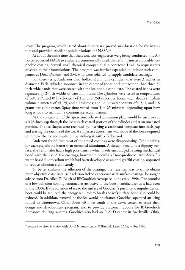
story. The program, which lasted about three years, proved an education for the inven-tors and provided excellent public relations for NASA.10
At about the same time that these amateur-night tests were being conducted, the AirForce requested NASA to evaluate a commercially available Teflon paint as a possible ice-phobic coating. Several small chemical companies also contacted Lewis to request testsof some of their formulations. The program was further expanded to include such com-panies as Dow, DuPont, and 3M, who were solicited to supply candidate coatings.
For these tests, Anderson used hollow aluminum cylinders that were 3 inches indiameter. Each cylinder, mounted in the center of the tunnel test section, had three 3-inch-wide bands that were coated with the ice-phobic candidate. The coated bands wereseparated by 2-inch widths of bare aluminum. The cylinders were tested at temperaturesof 30°, 25°, and 0°F; velocities of 100 and 250 miles per hour; water droplet medianvolume diameters of 15, 25, and 40 microns; and liquid water content of 0.5, 1, and 1.8grams per cubic meter. Spray time varied from 5 to 25 minutes, depending upon howlong it took to maintain a constant ice accumulation.
At the completion of the spray run, a heated aluminum plate would be used to cuta 0.25-inch gap through the ice at each coated portion of the cylinder and at an uncoatedportion. The ice shapes were recorded by inserting a cardboard template into each gapand tracing the outline of the ice. A subjective assessment was made of the force requiredto remove the ice accumulation by striking it with a Teflon rod.
Anderson found that most of the tested coatings were disappointing. Teflon paints,for example, did no better than uncoated aluminum. Although providing a slippery sur-face, the Teflon also had a high pore density which likely encouraged a strong mechanicalbond with the ice. A few coatings, however, especially a Dow-produced “Anti-Stick,” awater-based fluorocarbon which had been developed as an anti-graffiti coating, appearedto reduce adhesion significantly.
To better evaluate the adhesion of the coatings, the next step was to try to obtainmore objective data. Because Anderson lacked experience with surface coatings, he soughtadvice from Dr. Allen D. Reich of BFGoodrich Aerospace in the early 1990s. The promiseof a low-adhesion coating remained as attractive to the boot manufacturer as it had beenin the 1930s. If the adhesion of ice to the surface of Goodrich’s pneumatic impulse de-icerboot could be reduced, the energy required to break the ice’s surface bond also could bereduced. In addition, removal of the ice would be cleaner. Goodrich operated an icingtunnel in Uniontown, Ohio, about 40 miles south of the Lewis center, to assist theirdesign and development program, and to provide customer support for BFGoodrichAerospace de-icing systems. Goodrich also had an R & D center in Brecksville, Ohio,
The 1990s
159
10 Sexton interview; interview with David N. Anderson by William M. Leary, 23 September 2000.
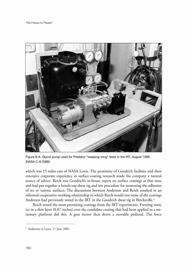
which was 15 miles east of NASA Lewis. The proximity of Goodrich facilities and theirextensive corporate experience in surface-coating research made the company a naturalsource of advice. Reich was Goodrich’s in-house expert on surface coatings at that timeand had put together a bench-top shear rig and test procedure for measuring the adhesionof ice to various surfaces. The discussions between Anderson and Reich resulted in aninformal cooperative working relationship in which Reich would test some of the coatingsAnderson had previously tested in the IRT in the Goodrich shear rig in Brecksville.11
Reich tested the most promising coatings from the IRT experiments. Freezing staticice in a thin layer (0.07 inches) over the candidate coating that had been applied to a sta-tionary platform did this. A gear motor then drove a movable pedestal. The force
“We Freeze to Please”
160
Figure 8–6. Glycol pump used for Predator “weeping wing” tests in the IRT, August 1996.
(NASA C-9-3380)
11 Anderson to Leary, 11 June 2001.

required to remove the ice was measured with a load cell. Reich could calculate adhesionforce with a simple mathematical formula. In these tests, the Dow coating also came outon top, displaying fairly repeatable adhesive strength that increased only slightly with anumber of ice removals.
While the Goodrich tests were encouraging, Anderson knew that impact ice had dif-ferent physical characteristics than static ice. In an attempt to obtain quantifiable resultswith impact ice in the IRT, he employed in the next series of tests a shear rig that hadbeen developed at the University of Akron by R. L. Scavuzzo and M. L. Chu. Based onthe earlier NASA device, it used a 1-inch-diameter cylinder that would be coated withtest material and mounted inside a thin sleeve. A window that was cut from the sleeveexposed a portion of the cylinder to the icing cloud. Ice accreting on the sleeve bondedthe cylinder to the sleeve at the window. Once the ice had accreted, the cylinder-sleeveassembly was removed and placed on a stand. The cylinder was then forced through thesleeve by a hydraulic press acting through a load cell. The force required to free thecylinder was recorded on a strip chart.
Anderson soon found that the mechanism suffered from two major problems. Icesometimes caused adjoining cylinder-sleeve assemblies to stick together, making disas-sembly difficult. Also, the cylinder often separated from the sleeve when removed fromthe test stand, especially with low adhesion coatings. As a result, no measurements couldbe obtained. In the end, Anderson considered the data that he obtained from the shearrig tests to be unreliable.
NASA technicians managed to devise a test stand that permitted shear-force meas-urements to be made in the tunnel without disturbing the coating specimens. Twocoatings stood out in the subsequent tests. Both the Dow “Anti-Stick” coating and a fluoropolymer-based DuPont coating reduced adhesive strength by 30 to 50 percent.These results were confirmed in the Goodrich tunnel. At this point, NASA concluded itswork on the ice-phobic project, leaving Goodrich and the chemical companies todevelop further a practical low-adhesive coating.12
One of the most innovative uses of the IRT during the 1990s came with tests of theeffects of lightning strikes on radomes. Because radomes were constructed from non-electrically conducting materials, they were vulnerable to being punctured or shatteredby lightning strikes. To minimize this danger, radomes initially had been fitted with anarrangement of solid metal bars, called diverters, that would conduct the lightning safelyto the airframe. Newer protection devices—segmented diverters—accomplished thesame purpose but caused less interference with radar performance. Verification of the
The 1990s
161
12 Anderson interview; David N. Anderson and Allen D. Reich, “Tests of the Performance of Coatings for Low
Ice Adhesion,” NASA TM 107399 (1997).

effectiveness of these devices was accomplished by simulated lightning strikes, usuallyconducted within indoor high-voltage laboratories. Even after having passed these certi-fication tests, however, the radomes continued to be vulnerable to lightning strikes,suggesting that atmospheric conditions—rain, ice, airflow—might influence the per-formance of the designs.13
Late in 1993, a consortium of government agencies and commercial companies inthe United States and Europe formed a joint program on the improvement of lightningand static protection of radomes. One of the objectives of the multi-year program was totest the segmented diverter system under simulated environmental conditions. The FAAsought the assistance of NASA-Lewis to conduct these tests. After an inspection of theIRT in February 1995 determined that the tunnel could accommodate the experiment,the tests were scheduled for October 1995.
“We Freeze to Please”
162
Figure 8–7. Predator icing test, Duluth, MN. (NASA C-97-01251)
13 Irvine to Michael S. Glynn, program manager, FAA Technical Center, 20 September 1995, records of the
icing branch, Glenn Research Center.

The lightning generator of the tests would be provided and operated by LightningTechnologies, Inc. The 500-kilovolt Marx-type impulse generator, standing 8 feet tall ona 3-foot metal base, produced high-voltage impulses reaching a peak amplitude of 500to 700 kilovolts in times selectable from 1 to 50 microseconds. This voltage could flashover between 0.5 and 1.5 meters of air. For the IRT tests, it was installed in the diffusersection of the tunnel, downstream from the usual test section. This larger area, in whichairstream velocities of up to 200 miles per hour could be reached, was necessary to con-tain the lightning generator and radome models.
IRT technicians went to great lengths to ensure that the experiments did not damagethe tunnel or its sensitive equipment. Just to be sure that no unforeseen effects occurred,the generator was operated at low voltage levels when tests began, and then it was slowlyincreased to normal test voltage amplitude. As it turned out, the visually impressiveweeklong tests took place without incident. A good deal of useful data was recorded toassist the FAA in the development of new certification standards.
Urgent projects generated by the military services always commanded a high priorityin the IRT. One such program during the 1990s involved the development of an ice-protection system for the Predator Unmanned Aerial Vehicle (UAV). Designated theRQ-1 by the Air Force, the Predator was manufactured by General Atomics AeronauticalSystems, Inc., without ice protection. It appeared in the mid-1990s as an effective recon-naissance platform that could be operated over high-risk areas without the danger ofhuman loss. Equipped with four state-of-the-art sensors, Predators could fly over targetedareas for nearly 40 hours. Essentially a powered glider, the air vehicle was a mid-wingmonoplane with a slender fuselage that housed the payload and fuel. It featured a highaspect ratio wing and an inverted-V tail.
A prototype Predator participated with great success in the annual air defense exer-cises that were held in the southwestern United States in the spring of 1995. Its firstoperational deployment came in July 1995. Based in Albania, the Predator flew surveil-lance missions over the Balkans until November 1995. A second European deploymenttook place in March 1996, with the Predators being based in Hungary.
These early missions proved successful, although the military became concernedover the vehicle’s lack of ice protection. The Predator’s natural laminar flow wing was sen-sitive to any form of contamination. Rain, for example, would cause it to descend. Itcould not operate at all in an icing environment, which limited its usefulness.
The Department of Defense’s Joint Project Office called upon NASA for assistancein the spring of 1996. The Air Force quickly fabricated three models for testing in theIRT. Researcher Andrew L. Reehorst began the test program on 5 August. He first placedin the tunnel a truncated half-fuselage model of the Predator that was complete withinlets and antenna. The main purpose of these experiments was to identify a suitablelocation for a Rosemount ultrasonic ice detector. The tests showed that the planned loca-
The 1990s
163
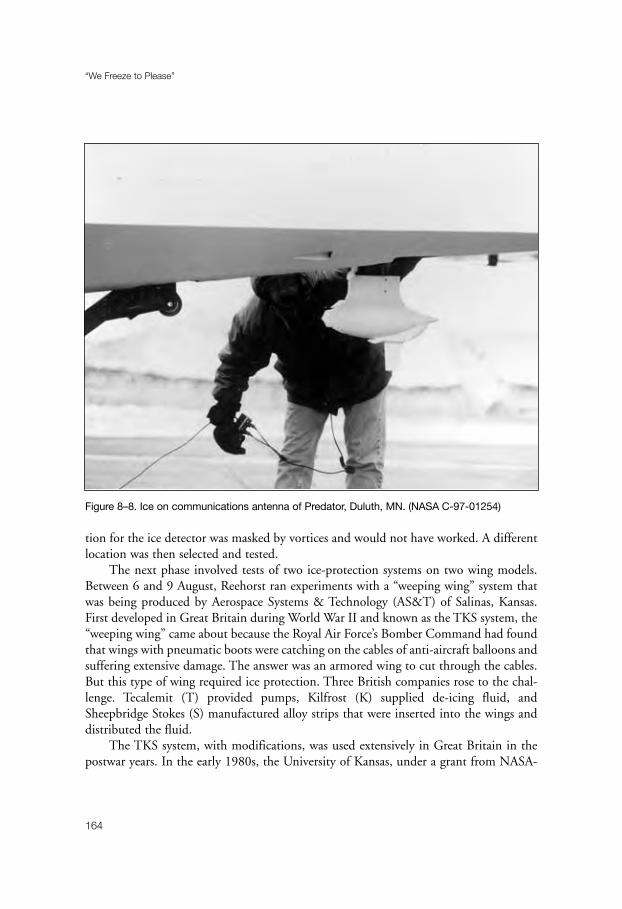
tion for the ice detector was masked by vortices and would not have worked. A differentlocation was then selected and tested.
The next phase involved tests of two ice-protection systems on two wing models.Between 6 and 9 August, Reehorst ran experiments with a “weeping wing” system thatwas being produced by Aerospace Systems & Technology (AS&T) of Salinas, Kansas.First developed in Great Britain during World War II and known as the TKS system, the“weeping wing” came about because the Royal Air Force’s Bomber Command had foundthat wings with pneumatic boots were catching on the cables of anti-aircraft balloons andsuffering extensive damage. The answer was an armored wing to cut through the cables.But this type of wing required ice protection. Three British companies rose to the chal-lenge. Tecalemit (T) provided pumps, Kilfrost (K) supplied de-icing fluid, andSheepbridge Stokes (S) manufactured alloy strips that were inserted into the wings anddistributed the fluid.
The TKS system, with modifications, was used extensively in Great Britain in thepostwar years. In the early 1980s, the University of Kansas, under a grant from NASA-
“We Freeze to Please”
164
Figure 8–8. Ice on communications antenna of Predator, Duluth, MN. (NASA C-97-01254)

Lewis, tested the system in the IRT. Using two general aviation airfoils, the Kansasresearchers examined two distribution methods—one that employed a stainless steelmesh and the other made from porous composite material.14
AS&T was formed in 1990 to build leading-edge TKS structures for general avia-tion aircraft. It grew rapidly and soon acquired the British manufacturers of the product.The TKS system tested on the Predator featured porous, laser-drilled titanium panels todistribute a glycol-based fluid to wings and horizontal and vertical stabilizers. A smallelectrically driven pump and storage tank completed the system, which weighed only 40pounds (without liquid) and consumed little power.15
Between 12 and 16 August 1996, Reehorst used the second wing section for experi-ments with the more innovative electro-mechanical de-icing system that was underdevelopment by Innovative Dynamics, Inc., (IDI) of Ithaca, New York. IDI’s Sonic PulseElectro-Expulsive De-icer (SPEED) had evolved from earlier work on Electro-ImpulseDe-Icing (EIDI) (see chapter five). As with EIDI, SPEED featured actuator coils that wereplaced behind the leading edge of the airfoil and applied impulsive loads directly to theaircraft skin. The rapid electrical acceleration debonded the ice, which was carried awayin the airstream. With major improvements in the activator coil and electronics, SPEEDhad performed well in earlier IRT tests, shedding ice as thin as 0.050 inches. As with theTKS system, SPEED offered a low-weight, low-power system of ice protection.16
Reehorst obtained excellent results with both the TKS and SPEED systems.Although SPEED was the more technologically advanced method of ice protection, theAir Force opted for the more proven TKS system. Flight tests of the Predator with the“weeping wing” took place at the Army’s test facility at Duluth, Minnesota, during thewinter of 1996–97. This was followed by a second series of flight tests in the winter of1997–98, leading to a decision to incorporate the TKS system on the “Block 2” (RQ-1B) series of Predators.17
The need for the ice-protected Predators was made abundantly clear to the Air Force whena RQ-1A crashed near Tuzla Air Base, Bosnia, due to icing on 18 April 1999. The Departmentof Defense removed the aircraft from the Balkans in the fall of 1999, due to the dangers from
The 1990s
165
14 On the University of Kansas tests, see Reinmann, R. J. Shaw, and W. A. Olsen, Jr., “Aircraft Icing Research
at NASA,” NASA TM 82919 (1982).15 David K. Henry, “TKS Ice Protection,” 4 May 2001. The author is indebted to Mr. Henry of AS&T for put-
ting together this historical account of the TKS system.16 Interview with Andrew L. Reehorst by William M. Leary, 22 September 2000; Reehorst to Leary, 4 May
2001; Innovative Dynamics, Inc., “Sonic Pulse Electro-Impulsive De-Icer.” The author is indebted to Mr.
Joseph J. Gerardi of IDI for information on the SPEED system.17 Reehorst to Leary, 4 May 2001.
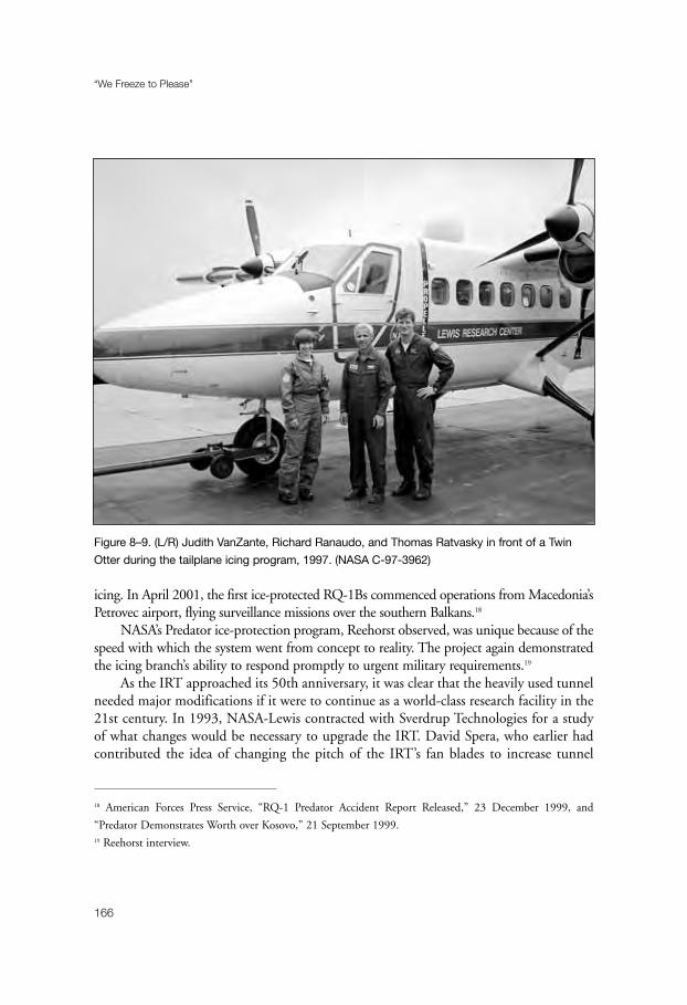
icing. In April 2001, the first ice-protected RQ-1Bs commenced operations from Macedonia’sPetrovec airport, flying surveillance missions over the southern Balkans.18
NASA’s Predator ice-protection program, Reehorst observed, was unique because of thespeed with which the system went from concept to reality. The project again demonstratedthe icing branch’s ability to respond promptly to urgent military requirements.19
As the IRT approached its 50th anniversary, it was clear that the heavily used tunnelneeded major modifications if it were to continue as a world-class research facility in the21st century. In 1993, NASA-Lewis contracted with Sverdrup Technologies for a studyof what changes would be necessary to upgrade the IRT. David Spera, who earlier hadcontributed the idea of changing the pitch of the IRT’s fan blades to increase tunnel
“We Freeze to Please”
166
Figure 8–9. (L/R) Judith VanZante, Richard Ranaudo, and Thomas Ratvasky in front of a Twin
Otter during the tailplane icing program, 1997. (NASA C-97-3962)
18 American Forces Press Service, “RQ-1 Predator Accident Report Released,” 23 December 1999, and
“Predator Demonstrates Worth over Kosovo,” 21 September 1999.19 Reehorst interview.
speed, was the principal investigator for Sverdrup. He suggested that significant improve-ments be made in flow quality, water spray uniformity, load balance accuracy, and thedrive fan system. These modifications would allow the effects of icing and de-icing onlift and drag to be measured more accurately under a wider range of conditions. He esti-mated that the project would cost $20 million.20
Spera sent his plan to facility manager Vincent, who submitted it up the NASA chain-of-command as a national facilities study project. As it turned out, the Spera plan becamethe basis for an even more extensive tunnel modification program that had been developedby Irvine while he was working in the Aeronautical Facilities Engineering Division. Workbegan late in 1993 with structural repairs of the IRT’s pressure shell and supports.21
Work on the spray bar system got underway in September 1996. Under the existingarrangement, the uniform icing cloud covered approximately 30 percent of the test sec-tion area. The goal of the new system was to cover at least 60 percent. Relying uponempirical data from the existing system, the design team concluded that adding twospray bars would produce the desired icing cloud. With a total of ten bars, the newsystem could produce spray from up to 540 locations. In addition, a second water linethat was connected to each nozzle holder permitted rapid changes between two sets ofliquid water content/median volume diameter test conditions.
Two other important spray system changes were based on the experiences of theBoeing Research Aerodynamic Icing Tunnel (BRAIT). Each spray nozzle in the Boeingfacility had a solenoid valve for electrical control. With this valve, it was possible toachieve exact air and water set points, and stabilized flow within 15 seconds. The settlingtime for NASA’s existing system, which used a supply valve located upstream on thewater header, was between 30 and 90 seconds, with a typical pressure overshoot of 10 to15 percent of the desired set points. NASA concluded an agreement with Boeing for theuse of their superior controls for the new IRT spray bar system.22
Boeing’s experience also influenced the selection of an aerodynamic shape for thespray bars. The flow quality in the Boeing tunnel was superior to that in the existing IRTin part because of Boeing’s use of aerodynamically shaped spray bars. NASA’s design teamadopted a modified NACA 0024 airfoil shape for the new spray bars in hope ofimproving flow quality.
The 1990s
167
20 David W. Vincent, “Upgrade of the Icing Research Tunnel (IRT) at the Lewis Research Center,” 9 July 1993.
The author is indebted to Mr. Spera for a copy of this document.21 Lewis News, 3 December 1993.22 Thomas B. Irvine, John R. Oldenburg, and David W. Sheldon, “New Icing Cloud Simulation System at the
NASA Glenn Research Center Icing Research Tunnel,” NASA TM-1999-208891 (June 1999); George E. Cain
to Leary, 3 November 2000.
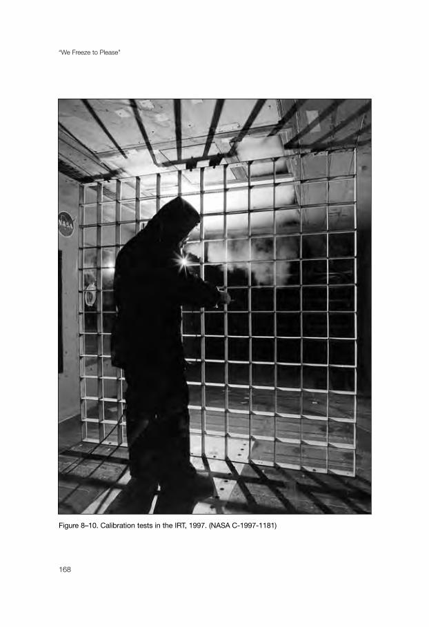
“We Freeze to Please”
168
Figure 8–10. Calibration tests in the IRT, 1997. (NASA C-1997-1181)

Construction of the new spray bar system took until January 1997. At this point,Robert Ide and Jose Gonzalez assumed responsibility for icing cloud and aerodynamiccalibration. Gonzalez showed that test section aerodynamic flow quality was not meas-urably different with the new system, with the exception of an overall decrease inturbulence. Ide’s cloud calibration produced a set of calibration curves that would beused by tunnel operators to set spray bar conditions to achieve the desired icing cloudcharacteristics. He also was able to achieve a uniform icing cloud covering 60 percent ofthe test section.
The IRT reopened with the new spray bar system in May 1997. All went well atfirst, but then the facility became “unstable,” that is, icing cloud uniformity becameimpossible to achieve. Facility manager Irvine, who had replaced Vincent in March 1995,promptly launched an investigation, checking the aging heat exchanger, new spray bars,and everything else that he could think about. “Nothing,” Irvine recalled, “could befound.” Finally, he brought in Edward J. Zampino from the Safety Office. Zampinodeveloped a fault tree analysis and systematically investigated all possible root causes ofthe problem. He never managed to identify the reason for the instability; although, agood deal was learned about the operation of the tunnel during the investigation. Afterfour or five frustrating months, the problem simply cleared up. It then took another fourmonths to recalibrate the tunnel. When this tedious job was finished, the IRT’s stafffaced months of overwork to complete critical tunnel projects that had been delayed.Irvine recalls this as a difficult period in the operation of the facility when it was hard tokeep up morale.23
With the IRT scheduled to shut down in the spring of 1999 for replacement of theheat exchanger, work in the heavily used facility intensified during the first part of the year.January began with a continuation of the Tailplane Icing Program. “We were looking togain a broader understanding of the aero-performance effects of icing on a business jethorizontal tail,” researcher Ratvasky pointed out, “and to develop test methods using sub-scale models with artificial ice shapes to obtain useful data for full-scale comparison.”With the support of engineers from Learjet, Ratvasky ran 45.1 hours of icing tests of afull-scale horizontal tail of a Lear business jet that produced realistic ice shapes. Moldswere made of two shapes, which were subsequently made into casts that were used for full-scale empennage tests in the 40 x 80-foot wind tunnel at the Ames laboratory.24
David Loe of Bell Helicopter Textron followed Ratvasky in the tunnel. Loe spent 79hours in the IRT, collecting ice shapes on the empennage of the Bell Agusta 609 tilt rotor.
The 1990s
169
23 Irvine interview.24 Ratvasky to Leary, 24 July 2001; Icing Research Tunnel, “1999 Schedule and Model Information Report,”
copy in the files of the icing branch, Glenn Research Center.
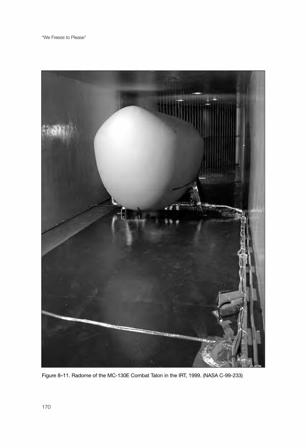
“We Freeze to Please”
170
Figure 8–11. Radome of the MC-130E Combat Talon in the IRT, 1999. (NASA C-99-233)

The casts resulting from these shapes would be attached to the innovative civil tilt rotor forthe Zero-G pushover tests that the FAA now required as part of icing certification.25
The month ended with 27.9 hours of tests that had been requested by the U.S. Air Force,which had been experiencing difficulties with the hot air anti-ice system used for radomes onMC-130 Combat Talons. The radome for the aircraft used by Air Force special forces hadbeen redesigned from the one on standard C-130 transports in order to accept new terrainfollowing radar. When the anti-ice system had been turned on, however, the radome had atendency to overheat and implode. In three inflight tests behind an ice tanker, a modifiedanti-ice system had failed to meet specifications. Rather than remove the aircraft from opera-tional status for further tests, the Air Force decided to continue testing in the IRT.26
With the assistance of personnel from Lockheed-Martin, IRT technicians built a rigto hold a Combat Talon radome for icing experiments. It turned out that the anti-icevalving system was putting out too much hot air, causing cracks in the radome. The solu-tion to the problem was simply to adjust the valving system so that enough hot air wasgenerated to keep ice off the radome without cooking it.27
February brought a month-long series of droplet impingement studies that wereconducted in partnership with Wichita State University (WSU). A total of 147.3 hoursof tunnel time was devoted to experiments with models of several wing sections and aninlet that had been selected following consultation with the aircraft industry. The pur-pose of the tests was to expand the droplet impingement database that was used to designice-protection systems on new aircraft and to validate ice-prediction computer codes.
The technique used for the droplet impingement experiments was a modern versionof the dye tests of the 1950s. Areas of interest on a model would be covered with blotterstrips, then sprayed with a dye of known concentration. Measuring the amount of dyeon each of the strips would determine the rate of water impingement for the region. Themore recent version, however, used a high-performance spray system that had been devel-oped at Wichita State. Mounted on the IRT spray bars, it generated short, stable spraysof less than 10 seconds. Unlike the previous red dye, the WSU system sprayed blue dye.This was because the measurement of dye concentration on the blotter strips was accom-plished by bouncing a laser beam off the surface of the strips. The intensity of thereflected light could be measured and correlated to the amount of dye on the strips. Theblue gave the best reflective results for the red laser beam.
Although the 1950s system, as noted earlier, was both labor intensive and time con-suming, the newer version also posed challenges for the experimenters. “The impingement
The 1990s
171
25 Leary telephone interview with Roger E. Aubert, 24 July 2001.26 “Anti-Ice Test Plan,” 25 November 1998, icing branch files.27 Sexton interview.

tests are rather lengthy and grueling,” researcher Colin S. Bidwell explained, “because ofthe time required to install the customized spray system and the number of models tested.The spray system takes several weeks to install and calibrate. A typical model is tested forone to three days and involved [in] aero-testing (for model surface pressures) and impinge-ment tests for various attitudes and spray droplet diameters. Each of the conditionsrequires three to five repeats to generate a useful statistical average. A typical model mightgenerate 300 blotter strips.”
The 1999 impingement experiments were the third set of tests that had been con-ducted since 1985. Funded by the FAA and Boeing, and with manpower and modelsupport from a variety of manufacturers, the program was scheduled to conclude withthe final series of tests in September 2001.28
“We Freeze to Please”
172
Figure 8–12. Icing tests of Sikorsky S-92 inlet in the IRT, 1998. (NASA C-98-1348)
28 Bidwell to Leary, 23 July 2001; Michael Papadakis, Marlin D. Breer, Neil C. Craig, and Bidwell, “Experimental
Water Droplet Impingement Data on Modern Aircraft Surfaces,” AIAA Paper 91-0445 (January 1991).

March saw 44 hours of tests performed on the wing section of the Bell 609 tiltrotor—this time to demonstrate the operation of the de-icing system and to collect iceshapes for tests of performance degradation between de-icing cycles. In addition, exper-iments were conducted with the horizontal tail sections of two business jets. Over 14hours of tunnel time involved icing tests for the certification of the Sino SwearingenSJ30-2, a seven-place, twin jet engine business aircraft. Icing certification tests of theRaytheon Premier 1, another twin jet business airplane, required 72 hours of tunneltime. The low-energy ice-protection system for the Premier 1, developed by Cox &Company of New York City with support from Glenn’s Small Business InnovativeResearch funding program, featured an imaginative combination of thermal anti-icingfor the leading edge of the airfoil and electro-mechanical expulsion de-icing for the areapast the heated edge. Further along in the certification process, the Premier 1 went on toreceive icing approval from the FAA in May 2001. All tests in March involved reim-bursable funding—with $130,354 for Bell Textron, $54,556 for Swearingen, and$215,242 for Raytheon.29
The period between March 31 and April 20 witnessed 128.3 hours of testing thatwas designed to provide rotorcraft airfoil ice-accretion data for correlation with theLEWICE code and to evaluate de-icing systems for application to rotorcraft airfoils. TheNational Rotorcraft Technology Center (NRTC) of the Rotorcraft Industry Associationhad initiated in 1997 a project to develop rotor blade ice-protection systems for conven-tional helicopters and tilt-rotor aircraft. NRTC researchers began by evaluating anextensive list of ice-protection methods. Ice-phobic material, they concluded, lacked theability to shed ice and to withstand rain and other sources of erosion. They then wrotegeneric specifications for selecting manufacturers to have their ice-protection systemstested. Three suppliers responded with an electro-expulsive and two electro-thermal sys-tems. In April 1999, the systems were installed on a Sikorsky SC2110 airfoil (15-inchchord) in the IRT. Under the direction of Robert J. Flemming, chief of experimentalaeromechanics and icing at the Sikorsky Aircraft Corporation, the NRTC team acquiredice-accretion and de-icing data for the test models, along with airfoil lift, drag, andpitching moment measurements. The tests revealed that the ice-shedding capabilities ofthe electro-thermal systems were superior to the electro-expulsive system for rotor bladeapplications. As a result of the IRT tests, Sikorsky selected an electro-thermal system forits S-97 helicopter.30
The 1990s
173
29 IRT, “1999 Schedule.”30 Flemming to Leary, 23 July 2001, enclosing “Rotor Ice Protection Systems Development Tests in the Icing
Research Tunnel.”

In all, the IRT operated for an impressive total of 639.2 hours and generated$726,008 in reimbursable funds before the tunnel was released to East/WestConstruction on 10 May 1999.31
While the Carrier heat exchanger had been an engineering marvel when installed inthe early 1940s, it had deteriorated badly over the years. Leaks were commonplace. Thesystem held 60,000 pounds of R-12 refrigerant, plus a small reserve. It would lose theentire supply of R-12 over a year’s time, and the cost of the refrigerant had risen from 50cents to $3 a pound. Technicians controlled the leaks by pinching off tubes, which meantthat the temperature of the air flowing over the exchanger became less uniform.Maintaining the Carrier unit was accounting for approximately 100 hours of tunneldowntime per year by the 1990s. “Although a new heat exchanger made sense,” facility
“We Freeze to Please”
174
Figure 8–13. Bell Augusta 609 tilt rotor empennage during icing tests, 1999: (L/R) technicians
Tom Lawrence and Michael Lupton. (NASA C-99-204)
31 IRT, “1999 Schedule.”
manager Irvine recalled, “there was still the thought that it would mean tearing apart anational treasure that was operational.” Nonetheless, it had to be done.32
Once the decision was made, everyone connected with the project worked hard toensure that they got it right. Again, as Irvine pointed out, “the Boeing experience wasindispensable.” The BRAIT heat exchanger was a state-of-the-art flat face unit that meas-ured 19’8” by 34’8”. Using environmentally friendly R-134a refrigerant, it was locatedbetween corners “C” and “D” in the tunnel. (Boeing used the designation #3 and #4.)Air from the fan flowed around corner C, passed over the heat exchanger, then exited viacorner D toward the spray bars and test chamber.
Dr. Seetharam H. Chintamani, a talented Boeing aerodynamicist, recognized thatthe design of the turning vanes in corner C was crucial. In order for the heat exchangerto maintain temperature uniformity of +/- 1°F in the test section, the manufacturerneeded an approach velocity of no more than 15 feet per second, with a maximum vari-ation of +/- 10 percent. Using a combination of computational fluid mechanics andempirical methods, Chintamani selected various turning vane designs for one-fifth-scalemodel tests. He found that a simple cambered flat plate with a 90° turning vane offeredthe desired flow qualities; however, it suffered from periodic flow separation. Chintamanicame up with a unique leading-edge addition that solved the problem. He also fine-tuned the turning vanes at the D corner to ensure velocity uniformity for the air as itapproached the spray bars.33
The Boeing innovations produced a far superior distribution of temperature andflow quality than was found in the IRT. “Without the Boeing model and experience,”Irvine pointed out, “it is unlikely that NASA would have had the engineering insight—or courage—to go ahead with the redesign of the heat exchanger.”34
NASA also selected the flat-face heater exchanger, configured as two side-by-side units,each with its own coolant supply of R-134a refrigerant and return pipes. Because the existingheat exchanger and surrounding steel structure were so closely connected, this meant thatthe Carrier unit could not be replaced without major structural modifications. The width ofthe tunnel duct between corners C and D had to be increased from 29.2 to 49.2 feet. Thisadded width necessitated new turning vanes in both corners. There would be sixteen aero-dynamically designed vanes at each corner. The shape of the vanes in corner C slowed down
The 1990s
175
32 Sexton interview; Irvine interview.33 Chintamani to Leary, 29 September 2000; Chintamani and R. Steven Sawyer, “Experimental Design of the
Expanding Third Corner for the Boeing Research Aerodynamic Icing Tunnel,” AIAA paper 92-0031, presented
at the 30th Aerospace Sciences Meeting and Exhibit, 6–9 January, Reno, NV. The author is indebted to Dr.
Chintamani for a copy of this paper and other material relating to the design of the Boeing tunnel.34 Irvine interview.

“We Freeze to Please”
176
Figure 8–14. Ice shapes, 1999. (NASA C-99-191)

the air flow as it passed over the heat exchanger, while the vanes in corner D speeded up theflow as it approached the spray bars. Unlike the Boeing tunnel, which used the Chintamani-designed closely spaced curved steel plates as turning vanes, the IRT’s designers selected thickcambered airfoils, both for reasons of accessibility and aerodynamic performance.35
A design contract for the modification was awarded to Aero System Engineering,Inc., of St. Paul, Minnesota. The company developed project design criteria, producedfinal design drawings and specifications for the new C–D leg of the tunnel, and devel-oped subcontractor specifications. Cloudy & Britton, Inc., of Mountlake Terrace,Washington, the builder of the BRAIT heat exchanger, contributed the preliminarydesign for the IRT replacement unit. Frigid Coil/Imeco, Inc., of Santa Fe Springs,California, did final design and fabrication of the two side-by-side heat exchangers.36
Irvine vividly recalls the morning of 10 May 1999, when demolition work began. Alarge hydraulic cutter (“the jaws of death”) was brought in to cut up the old heatexchanger. It was an emotional experience to witness the destruction of a nationaltreasure. He remembers thinking, “I hope that we were doing the right thing.”37
The construction went smoothly, and the tunnel was ready for reactivation tests on23 November 1999. Cloud calibration proved a major challenge for Robert Ide. Becauseof the changes made to the quality of the airflow entering the spray bar section, hundredsof nozzles had to be repositioned in order to obtain maximum uniformity in ice accre-tion in the test section. As it turned out, the improved flow quality of the air approachingthe spray bars had a small negative effect on the uniformity of the icing cloud, as the tur-bulence produced by the previous system had actually helped to mix the water dropletsinto a more uniform cloud. Tunnel activation, with its startup challenges, took 571.1hours. Finally, all was ready and the tunnel went back on line in July 2000. As of 17November 2000, the modified facility had operated for 978 hours without incident.38
Icing branch chief Bond has pronounced himself “very satisfied” with the construc-tion results. In 1994, a peer review had pointed out that poor airflow quality was one ofthe tunnel’s major drawbacks. This had now been remedied. The airflow qualities, Bondnoted, had been significantly improved, as had temperature uniformity.39
The 1990s
177
35 Irvine, Susan L. Kevdzija, David W. Sheldon, and David A. Spera (Dynacs Engineering Company),
“Overview of the Icing and Flow Quality Improvements Program for the NASA Glenn Icing Research Tunnel,”
NASA TM-2001-210686 (February 2001).36 Ibid.37 Irvine interview.38 Irvine et al., TM-2001-210686.39 Douglas J. Silva to Reinmann, enclosed copy of the NASA-LeRC Icing Research Peer Report, 23 March
1994, History Office, GRC; Bond interview.

Bond sees a bright future for the IRT. Outside requests for use of the facility aregreater than ever, and there is a backlog of nearly two years. A decision by Boeing to shutdown its icing tunnel will only increase the competition for IRT time. Pressure on theaircraft industry to develop new regional transports will generate significant work for thetunnel. Demands to investigate large droplet icing continue. The rotorcraft industry’ssearch for ice-protection systems means work for the IRT, as does all-weather require-ments for unmanned reconnaissance vehicles. NASA will continue to develop newprotection technologies and improve computer prediction codes. Without a doubt, theIRT will remain the nation’s premier icing research facility for the foreseeable future.
“We Freeze to Please”
178
Figure 8–15. Demolition of Corner D and original Carrier heat exchanger, 1999.
(NASA C-99-1452)

179
Essay on Sources
A central body of records on the icing research that has been conducted at theNACA/NASA Lewis-Glenn laboratory does not exist. While seeking to identify materialto support this study, historians and archivists at the Glenn Research Laboratory searchedthrough stored record collections, as well as long-unopened file cabinets at the IcingResearch Tunnel, in an effort to locate pertinent documents. They uncovered only ahandful of letters, memoranda, and other primary sources, which are now located in theHistory Office at Glenn. Inspection of the holdings of the History Office at NASAHeadquarters also revealed only a limited collection of documents bearing on icingresearch. Icing material in Record Group 255 at the National Archives and RecordsAdministration proved neither easy to identify nor especially helpful. No doubt, addi-tional material is buried in the collection. The best documentary source on icing researchis in file RA 247 at the Langley Historical Archive, Floyd L. Thompson TechnicalLibrary, Langley Research Center, Hampton, Virginia. This rich collection, however,covers only icing research prior to 1944.
Secondary sources on icing research are few and far between. There is a fine essay byGlenn E. Bugos, “Lew Rodert, Epistemological Liaison, and Thermal De-Icing at Ames,”in Pamela E. Mack (ed.), From Engineering Science to Big Science: The NACA and NASACollier Trophy Research Project Winners (NASA SP-4219, 1998), pp. 29–58. Bugos, how-ever, has little to say about events in Cleveland due to the focus of his study. There is alsoa chapter on icing research in George W. Gray, Frontiers of Flight: The Story of NACAResearch (New York: Alfred A. Knopf, 1948), but, again, the spotlight is on Rodert.Michael H. Gorn kindly supplied me with a draft chapter on icing flight research fromhis now published study, Expanding the Envelope: Flight Research at the NACA and NASA,1915–1988 (Lexington: University Press of Kentucky, 2001), which proved mosthelpful. Finally, Virginia P. Dawson’s excellent Engines and Innovation: Lewis Laboratoryand American Propulsion Technology (NASA SP-4306, 1991), not only provided the con-text in which icing research took place at Lewis, but also briefly discussed theconstruction of the IRT and its subsequent use.

Two published sources in icing that are aimed at the manufacturers, operators, andregulators of aircraft contain much useful information, much of it technical in character.Known as “the icing bible,” Federal Aviation Administration Technical Center, AircraftIcing Handbook (DOT/FAA/CT-88/8-1, 3 vols., 1991), is a rich source of material on thetopic. Also helpful is Flight Safety Foundation, Protection Against Icing: A ComprehensiveOverview, a special issue of Flight Safety Digest, vol. 16 (June–September 1997).
With only sparse documentation in terms of letters, memoranda, journals, and the like,the story of icing research at the Cleveland laboratory has had to rely primarily on technicalreports, plus oral history and correspondence with people who were there. Lewis-Glennresearchers published hundreds of technical notes, research reports, research memoranda, anda variety of other documents on icing research. Although mainly highly technical in nature,these reports also usually contained descriptive information on the background of variousprojects. Several of these reports merit special mention. Selected Bibliography of NACA-NASAAircraft Icing Publications, NASA Technical Memorandum 81651 (August 1981), not onlysurveys the literature for the 1944–1958 era of icing research, but also contains microfichecopies of all important technical documents. It is a gold mine of information. Also, John J.Reinmann and his colleagues issued a series of reports on the state of icing research at NASA.They are Reinmann, R. J. Shaw, and W. A. Olsen, Jr., Aircraft Icing Research at NASA, NASATechnical Memorandum 82919 (1982); Reinmann, Shaw, and Olsen, NASA Lewis ResearchCenter’s Program on Icing Research, NASA Technical Memorandum 83031 (1983); Reinmann,Shaw, and Richard J. Ranaudo, NASA’s Program on Icing Research and Technology, NASATechnical Memorandum 101989 (1989); Reinmann, NASA’s Aircraft Icing TechnologyProgram, NASA Technical Memorandum 104518 (1991); and Reinmann, “Icing: Accretion,Detection, Protection,” in Advisory Group for Aerospace Research and Development,AGARD Lecture Series 197: Flight in an Adverse Environment (NATO, 1994), section 4, pp.1–27. Copies of the NACA/NASA technical documents can be found in most major researchlibraries. Also, a number of the reports are now available on the Worldwide Web athttp://naca.larc.nasa.gov and http://techreports.larc.nasa.gov. The Glenn Research Center has aWeb site at http://www.grc.nasa.gov. For the icing branch, see http://icebox.grc.nasa.gov. TheIRT has its own Web site at http://www.grc.nasa.gov/WWW/IRT/
While the technical reports document the nature of the NACA/NASA icingresearch, they have to be supplemented by oral history in order to understand the con-text in which they were done. A list of individuals who contributed to this study follows.An * indicates that a taped interview was conducted and a copy is located in the NASAHistory Office in Washington, DC, along with pertinent correspondence.
Richard I. AdamsDavid N. Anderson*Roger J. AubertColin S. Bidwell
“We Freeze to Please”
180

Bernard J. BlahaThomas H. Bond*George E. CainSeetharam H. ChintamaniHarold H. ChristensonDavid EllisJohn H. EndersRobert J. FlemmingThomas F. Gelder*Joseph GerardiUwe von GlahnDavid K. HenryEugene G. HillThomas B. Irvine*Susan L. KevdzijaJames K. LuersPorter J. Perkins*Andrew A. PetersonRichard J. RanaudoThomas P. Ratvasky*Andrew L. Reehorst*John J. Reinmann*Robert J. Shaw*Jaiwon ShinRaymond G. Sotos*David A. SperaDavid SweetAllen R. TobiasonDavid W. Vincent*Halbert WhitakerHarold Zager*Jane Gavlak Zager*
Essay on Sources
181
183
NASA History Series
Reference Works, NASA SP-4000:
Grimwood, James M. Project Mercury: A Chronology. NASA SP-4001, 1963.
Grimwood, James M., and C. Barton Hacker, with Peter J. Vorzimmer. Project GeminiTechnology and Operations: A Chronology. NASA SP-4002, 1969.
Link, Mae Mills. Space Medicine in Project Mercury. NASA SP-4003, 1965.
Astronautics and Aeronautics, 1963: Chronology of Science, Technology, and Policy. NASASP-4004, 1964.
Astronautics and Aeronautics, 1964: Chronology of Science, Technology, and Policy. NASASP-4005, 1965.
Astronautics and Aeronautics, 1965: Chronology of Science, Technology, and Policy. NASASP-4006, 1966.
Astronautics and Aeronautics, 1966: Chronology of Science, Technology, and Policy. NASASP-4007, 1967.
Astronautics and Aeronautics, 1967: Chronology of Science, Technology, and Policy. NASASP-4008, 1968.
Ertel, Ivan D., and Mary Louise Morse. The Apollo Spacecraft: A Chronology, Volume I,Through November 7, 1962. NASA SP-4009, 1969.
Morse, Mary Louise, and Jean Kernahan Bays. The Apollo Spacecraft: A Chronology,Volume II, November 8, 1962–September 30, 1964. NASA SP-4009, 1973.

Brooks, Courtney G., and Ivan D. Ertel. The Apollo Spacecraft: A Chronology, Volume III,October 1, 1964–January 20, 1966. NASA SP-4009, 1973.
Ertel, Ivan D., and Roland W. Newkirk, with Courtney G. Brooks. The Apollo Spacecraft:A Chronology, Volume IV, January 21, 1966–July 13, 1974. NASA SP-4009, 1978.
Astronautics and Aeronautics, 1968: Chronology of Science, Technology, and Policy. NASASP-4010, 1969.
Newkirk, Roland W., and Ivan D. Ertel, with Courtney G. Brooks. Skylab: A Chronology.NASA SP-4011, 1977.
Van Nimmen, Jane, and Leonard C. Bruno, with Robert L. Rosholt. NASA HistoricalData Book, Volume I: NASA Resources, 1958–1968. NASA SP-4012, 1976, rep. ed. 1988.
Ezell, Linda Neuman. NASA Historical Data Book, Volume II: Programs and Projects,1958–1968. NASA SP-4012, 1988.
Ezell, Linda Neuman. NASA Historical Data Book, Volume III: Programs and Projects,1969–1978. NASA SP-4012, 1988.
Gawdiak, Ihor Y., with Helen Fedor, compilers. NASA Historical Data Book, Volume IV:NASA Resources, 1969–1978. NASA SP-4012, 1994.
Rumerman, Judy A., compiler. NASA Historical Data Book, 1979–1988: Volume V,NASA Launch Systems, Space Transportation, Human Spaceflight, and Space Science. NASASP-4012, 1999.
Rumerman, Judy A., compiler. NASA Historical Data Book, Volume VI: NASA SpaceApplications, Aeronautics and Space Research and Technology, Tracking and DataAcquisition/Space Operations, Commercial Programs, and Resources, 1979–1988. NASASP-2000-4012, 2000.
Astronautics and Aeronautics, 1969: Chronology of Science, Technology, and Policy. NASA SP-4014, 1970.
Astronautics and Aeronautics, 1970: Chronology of Science, Technology, and Policy. NASASP-4015, 1972.
“We Freeze to Please”
184
Astronautics and Aeronautics, 1971: Chronology of Science, Technology, and Policy. NASASP-4016, 1972.
Astronautics and Aeronautics, 1972: Chronology of Science, Technology, and Policy. NASASP-4017, 1974.
Astronautics and Aeronautics, 1973: Chronology of Science, Technology, and Policy. NASASP-4018, 1975.
Astronautics and Aeronautics, 1974: Chronology of Science, Technology, and Policy. NASASP-4019, 1977.
Astronautics and Aeronautics, 1975: Chronology of Science, Technology, and Policy. NASA SP-4020, 1979.
Astronautics and Aeronautics, 1976: Chronology of Science, Technology, and Policy. NASA SP-4021, 1984.
Astronautics and Aeronautics, 1977: Chronology of Science, Technology, and Policy. NASA SP-4022, 1986.
Astronautics and Aeronautics, 1978: Chronology of Science, Technology, and Policy. NASA SP-4023, 1986.
Astronautics and Aeronautics, 1979–1984: Chronology of Science, Technology, and Policy.NASA SP-4024, 1988.
Astronautics and Aeronautics, 1985: Chronology of Science, Technology, and Policy. NASA SP-4025, 1990.
Noordung, Hermann. The Problem of Space Travel: The Rocket Motor. Edited by ErnstStuhlinger and J. D. Hunley, with Jennifer Garland. NASA SP-4026, 1995.
Astronautics and Aeronautics, 1986–1990: A Chronology. NASA SP-4027, 1997.
Astronautics and Aeronautics, 1990–1995: A Chronology. NASA SP-2000-4028, 2000.
NASA History Series
185

Management Histories, NASA SP-4100:
Rosholt, Robert L. An Administrative History of NASA, 1958–1963. NASA SP-4101,1966.
Levine, Arnold S. Managing NASA in the Apollo Era. NASA SP-4102, 1982.
Roland, Alex. Model Research: The National Advisory Committee for Aeronautics,1915–1958. NASA SP-4103, 1985.
Fries, Sylvia D. NASA Engineers and the Age of Apollo. NASA SP-4104, 1992.
Glennan, T. Keith. The Birth of NASA: The Diary of T. Keith Glennan. J. D. Hunley, edi-tor. NASA SP-4105, 1993.
Seamans, Robert C., Jr. Aiming at Targets: The Autobiography of Robert C. Seamans, Jr.NASA SP-4106, 1996.
PPrroojjeecctt HHiissttoorriieess,, NNAASSAA SSPP--44220000::
Swenson, Loyd S., Jr., James M. Grimwood, and Charles C. Alexander. This New Ocean: A History of Project Mercury. NASA SP-4201, 1966; rep. ed. 1998.
Green, Constance McLaughlin, and Milton Lomask. Vanguard: A History. NASA SP-4202, 1970; rep. ed. Smithsonian Institution Press, 1971.
Hacker, Barton C., and James M. Grimwood. On Shoulders of Titans: A History of ProjectGemini. NASA SP-4203, 1977.
Benson, Charles D., and William Barnaby Faherty. Moonport: A History of Apollo LaunchFacilities and Operations. NASA SP-4204, 1978.
Brooks, Courtney G., James M. Grimwood, and Loyd S. Swenson, Jr. Chariots for Apollo:A History of Manned Lunar Spacecraft. NASA SP-4205, 1979.
Bilstein, Roger E. Stages to Saturn: A Technological History of the Apollo/Saturn LaunchVehicles. NASA SP-4206, 1980, rep. ed. 1997.
SP-4207 not published.
“We Freeze to Please”
186

Compton, W. David, and Charles D. Benson. Living and Working in Space: A History ofSkylab. NASA SP-4208, 1983.
Ezell, Edward Clinton, and Linda Neuman Ezell. The Partnership: A History of the Apollo-Soyuz Test Project. NASA SP-4209, 1978.
Hall, R. Cargill. Lunar Impact: A History of Project Ranger. NASA SP-4210, 1977.
Newell, Homer E. Beyond the Atmosphere: Early Years of Space Science. NASA SP-4211,1980.
Ezell, Edward Clinton, and Linda Neuman Ezell. On Mars: Exploration of the Red Planet,1958–1978. NASA SP-4212, 1984.
Pitts, John A. The Human Factor: Biomedicine in the Manned Space Program to 1980.NASA SP-4213, 1985.
Compton, W. David. Where No Man Has Gone Before: A History of Apollo LunarExploration Missions. NASA SP-4214, 1989.
Naugle, John E. First Among Equals: The Selection of NASA Space Science Experiments.NASA SP-4215, 1991.
Wallace, Lane E. Airborne Trailblazer: Two Decades with NASA Langley’s Boeing 737Flying Laboratory. NASA SP-4216, 1994.
Butrica, Andrew J., editor. Beyond the Ionosphere: Fifty Years of Satellite Communication.NASA SP-4217, 1997.
Butrica, Andrew J. To See the Unseen: A History of Planetary Radar Astronomy. NASA SP-4218, 1996.
Mack, Pamela E., editor. From Engineering Science to Big Science: The NACA and NASACollier Trophy Research Project Winners. NASA SP-4219, 1998.
Reed, R. Dale, with Darlene Lister. Wingless Flight: The Lifting Body Story. NASA SP-4220, 1997.
NASA History Series
187

Heppenheimer, T. A. The Space Shuttle Decision: NASA’s Search for a Reusable SpaceVehicle. NASA SP-4221, 1999.
Hunley, J. D., editor. Toward Mach 2: The Douglas D-558 Program. NASA SP-4222,1999.
Swanson, Glen E., editor. “Before this Decade is Out . . .”: Personal Reflections on the ApolloProgram. NASA SP-4223, 1999.
Tomayko, James E. Computers Take Flight: A History of NASA’s Pioneering Digital Fly-by-Wire Project. NASA SP-2000-4224, 2000.
Morgan, Clay. Shuttle-Mir: The U.S. and Russia Share History’s Highest Stage. NASA SP-2001-4225, 2001.
Leary, William M. “We Freeze to Please”: A History of NASA’s Icing Research Tunnel andthe Quest for Flight Safety. NASA SP-2002-4226, 2002.
Mudgway, Douglas J. Uplink-Downlink: A History of the Deep Space Network1957–1997. NASA SP-2001-4227, 2001.
CCeenntteerr HHiissttoorriieess,, NNAASSAA SSPP--44330000::
Rosenthal, Alfred. Venture into Space: Early Years of Goddard Space Flight Center. NASASP-4301, 1985.
Hartman, Edwin P. Adventures in Research: A History of Ames Research Center,1940–1965. NASA SP-4302, 1970.
Hallion, Richard P. On the Frontier: Flight Research at Dryden, 1946-1981. NASA SP-4303, 1984.
Muenger, Elizabeth A. Searching the Horizon: A History of Ames Research Center,1940–1976. NASA SP-4304, 1985.
Hansen, James R. Engineer in Charge: A History of the Langley Aeronautical Laboratory,1917–1958. NASA SP-4305, 1987.
“We Freeze to Please”
188
Dawson, Virginia P. Engines and Innovation: Lewis Laboratory and American PropulsionTechnology. NASA SP-4306, 1991.
Dethloff, Henry C. “Suddenly Tomorrow Came . . .”: A History of the Johnson Space Center.NASA SP-4307, 1993.
Hansen, James R. Spaceflight Revolution: NASA Langley Research Center from Sputnik toApollo. NASA SP-4308, 1995.
Wallace, Lane E. Flights of Discovery: 50 Years at the NASA Dryden Flight Research Center.NASA SP-4309, 1996.
Herring, Mack R. Way Station to Space: A History of the John C. Stennis Space Center.NASA SP-4310, 1997.
Wallace, Harold D., Jr. Wallops Station and the Creation of the American Space Program.NASA SP-4311, 1997.
Wallace, Lane E. Dreams, Hopes, Realities: NASA’s Goddard Space Flight Center, The FirstForty Years. NASA SP-4312, 1999.
Dunar, Andrew J., and Stephen P. Waring. Power to Explore: A History of the MarshallSpace Flight Center. NASA SP-4313, 1999.
Bugos, Glenn E. Atmosphere of Freedom: Sixty Years at the NASA Ames Research CenterNASA SP-2000-4314, 2000.
GGeenneerraall HHiissttoorriieess,, NNAASSAA SSPP--44440000::
Corliss, William R. NASA Sounding Rockets, 1958–1968: A Historical Summary. NASA SP-4401, 1971.
Wells, Helen T., Susan H. Whiteley, and Carrie Karegeannes. Origins of NASA Names.NASA SP-4402, 1976.
Anderson, Frank W., Jr. Orders of Magnitude: A History of NACA and NASA, 1915–1980.NASA SP-4403, 1981.
NASA History Series
189
Sloop, John L. Liquid Hydrogen as a Propulsion Fuel, 1945–1959. NASA SP-4404, 1978.
Roland, Alex. A Spacefaring People: Perspectives on Early Spaceflight. NASA SP-4405,1985.
Bilstein, Roger E. Orders of Magnitude: A History of the NACA and NASA, 1915–1990.NASA SP-4406, 1989.
Logsdon, John M., ed., with Linda J. Lear, Jannelle Warren-Findley, Ray A. Williamson,and Dwayne A. Day. Exploring the Unknown: Selected Documents in the History of the U.S.Civil Space Program, Volume I, Organizing for Exploration. NASA SP-4407, 1995.
Logsdon, John M., editor, with Dwayne A. Day and Roger D. Launius. Exploring theUnknown: Selected Documents in the History of the U.S. Civil Space Program, Volume II,Relations with Other Organizations. NASA SP-4407, 1996.
Logsdon, John M., ed., with Roger D. Launius, David H. Onkst, and Stephen J. Garber.Exploring the Unknown: Selected Documents in the History of the U.S. Civil Space Program,Volume III, Using Space. NASA SP-4407, 1998.
Logsdon, John M., gen. ed., with Ray A. Williamson, Roger D. Launius, Russell J. Acker,Stephen J. Garber, and Jonathan L. Friedman. Exploring the Unknown: SelectedDocuments in the History of the U.S. Civil Space Program, Volume IV, Accessing Space.NASA SP-4407, 1999.
Logsdon, John M., general editor, with Amy Paige Snyder, Roger D. Launius, Stephen J.Garber, and Regan Anne Newport. Exploring the Unknown: Selected Documents in theHistory of the U.S. Civil Space Program, Volume V, Exploring the Cosmos. NASA SP-2001-4407, 2001.
Siddiqi, Asif A. Challenge to Apollo: The Soviet Union and the Space Race, 1945–1974.NASA SP-2000-4408, 2000.
MMoonnooggrraapphhss iinn AAeerroossppaaccee HHiissttoorryy,, NNAASSAA SSPP--44550000::
Launius, Roger D. and Aaron K. Gillette, comps. Toward a History of the Space Shuttle:An Annotated Bibliography. Monograph in Aerospace History, No. 1, 1992.
“We Freeze to Please”
190

Launius, Roger D., and J. D. Hunley, comps. An Annotated Bibliography of the ApolloProgram. Monograph in Aerospace History, No. 2, 1994.
Launius, Roger D. Apollo: A Retrospective Analysis. Monograph in Aerospace History, No.3, 1994.
Hansen, James R. Enchanted Rendezvous: John C. Houbolt and the Genesis of the Lunar-Orbit Rendezvous Concept. Monograph in Aerospace History, No. 4, 1995.
Gorn, Michael H. Hugh L. Dryden’s Career in Aviation and Space. Monograph inAerospace History, No. 5, 1996.
Powers, Sheryll Goecke. Women in Flight Research at NASA Dryden Flight Research CenterFrom 1946 to 1995. Monograph in Aerospace History, No. 6, 1997.
Portree, David S. F. and Robert C. Trevino.Walking to Olympus: An EVA Chronology.Monograph in Aerospace History, No. 7, 1997.
Logsdon, John M., moderator. Legislative Origins of the National Aeronautics and SpaceAct of 1958: Proceedings of an Oral History Workshop. Monograph in Aerospace History,No. 8, 1998.
Rumerman, Judy A., comp. U.S. Human Spaceflight, A Record of Achievement1961–1998. Monograph in Aerospace History, No. 9, 1998.
Portree, David S. F. NASA’s Origins and the Dawn of the Space Age. Monograph inAerospace History, No. 10, 1998.
Logsdon, John M. Together in Orbit: The Origins of International Cooperation in the SpaceStation. Monograph in Aerospace History, No. 11, 1998.
Phillips, W. Hewitt. Journey in Aeronautical Research: A Career at NASA Langley ResearchCenter. Monograph in Aerospace History, No. 12, 1998.
Braslow, Albert L. A History of Suction-Type Laminar-Flow Control with Emphasis onFlight Research. Monograph in Aerospace History, No. 13, 1999.
Logsdon, John M., moderator. Managing the Moon Program: Lessons Learned From Apollo.Monograph in Aerospace History, No. 14, 1999.
NASA History Series
191

Perminov, V. G. The Difficult Road to Mars: A Brief History of Mars Exploration in theSoviet Union is Monograph in Aerospace History, No. 15, 1999.
Tucker, Tom. Touchdown: The Development of Propulsion Controlled Aircraft at NASADryden. Monograph in Aerospace History, No. 16, 1999.
Maisel, Martin D., Demo J. Giulianetti, and Daniel C. Dugan. The History of the XV-15 Tilt Rotor Research Aircraft: From Concept to Flight. NASA SP-2000-4517, 2000.
Jenkins, Dennis R. Hypersonics Before the Shuttle: A Concise History of the X-15 ResearchAirplane. NASA SP-2000-4518, 2000.
Chambers, Joseph R. Partners in Freedom: Contributions of the Langley Research Center toU.S. Military Aircraft in the 1990s. NASA SP-2000-4519, 2000.
Waltman, Gene L. Black Magic and Gremlins: Analog Flight Simulations at NASA’s FlightResearch Center. NASA SP-2000-4520, 2000.
Portree, David S. F. Humans to Mars: Fifty Years of Mission Planning, 1950–2000. NASA SP-2001-4521, 2001.
Thompson, Milton O., with J. D. Hunley. Flight Research: Problems Encountered andWhat They Should Teach Us. NASA SP-2000-4522, 2000.
Tucker, Tom. The Eclipse Project. NASA SP-2000-4523, 2000.
“We Freeze to Please”
192