WDM/ DWDM Systems & Components - · PDF fileWDM/ DWDM Systems & Components J.K.Chhabra, Ex...
47
Transcript of WDM/ DWDM Systems & Components - · PDF fileWDM/ DWDM Systems & Components J.K.Chhabra, Ex...


POSSIBLE SOLUTIONS
Install more optical fiber
Increase TDM speed (shorter pulses)
Wavelength Division Multiplexing (WDM)
Optical Code Division Multiplexing(OCDMA)

4
OVERVIEW
Digital Transceiver
Digital Transceiver
Digital Transceiver
Digital Transceiver
Digital Transceiver
Digital Transceiver
Digital Transceiver
Digital Transceiver
Single Pair of Fibers
Single Pair of Fibers
Single Pair of Fibers
Single Pair of Fibers
Digital Transceiver
Digital Transceiver
Digital Transceiver
Digital Transceiver
Digital Transceiver
Digital Transceiver
Digital Transceiver
Digital Transceiver
WDM MUX WDM MUX
Single Pair of Fibers
Traditional Digital Fiber Optic Transport
Digital Fiber Optic Transport using WDM

5
OVERVIEW
WDM COMPONENTS
Optical Multiplexer
Optical De-multiplexer
Optical Add/Drop Multiplexer
(OADM)
l1
l2
l3
l1
l2
l3
Transponder
850/1310 15xx
l1
l2
l3
l1...n
l1...n

MULTIPLEXING
Time-division multiplexing
• Interleaves signals at slower rates
Frequency-division multiplexing
• Combines signals at different frequencies electronically to make composite signal
Wavelength-division multiplexing
• Sends signals at different wavelengths
• Like frequency multiplexing of radio spectrum
6

Problem:
Demand for massive increases in capacity
Immediate Solution:
Dense Wavelength Division Multiplexing
Longer term Solution:
Optical Fibre Networks
PROBLEMS AND SOLUTIONS

Multiple channels of information carried over the same fibre, each using an
individual wavelength
Attractive multiplexing technique
High aggregate bit rate without high speed electronics or modulation
Low dispersion penalty for aggregate bit rate
Very useful for upgrades to installed fibres
Realisable using commercial components, unlike OTDM
Loss, crosstalk and non-linear effects are potential problems
Wavelength
Division
Multiplexer
Wavelength
Division
Demultiplexerl
1A
l
2l
3
B
C
l
1X
l
2l
3
Y
Zl1 + l2 + l3
Fibre
WDM Overview
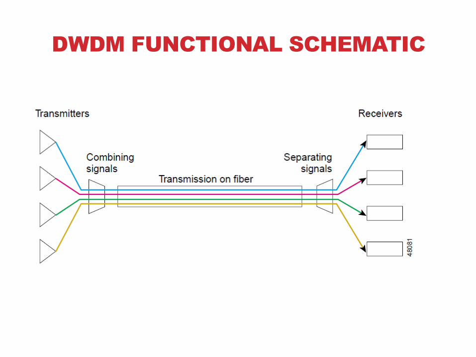
DWDM FUNCTIONAL SCHEMATIC

Transmitters
DWDM
Multiplexer
Power
AmpLine
Amp
Receive
Preamp
200 km
DWDM
DeMultiplexe
r
Each wavelength still behaves as if it has it own "virtual fibre"
Wavelengths can be added and dropped as required at
some intermediate location
ReceiversAdd/Drop
Mux/Demux
Optical
fibre
DWDM SYSTEM WITH ADD-DROP

Trend is toward smaller channel spacings, to incease the channel count
ITU channel spacings are 0.4 nm, 0.8 nm and 1.6 nm (50, 100 and 200 GHz)
Proposed spacings of 0.2 nm (25 GHz) and even 0.1 nm (12.5 GHz)
Requires laser sources with excellent long term wavelength stability, better than 10
pm
One target is to allow more channels in the C-band without other upgrades
Wavelength in nm
1550 15541551 1552 15531553
0.8 nm
Channel Spacing

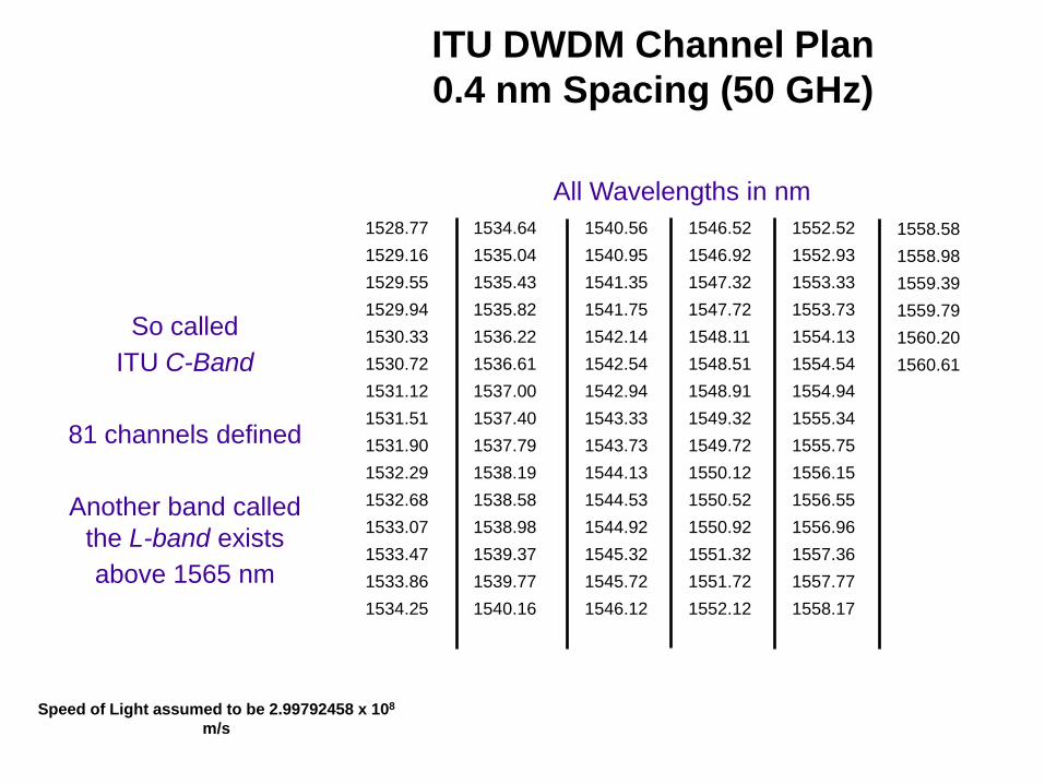
Speed of Light assumed to be 2.99792458 x 10⁸ m/s
1552.52
1553.33
1554.13
1554.94
1555.75
1556.55
1557.36
1558.17
1546.52
1547.32
1548.11
1548.91
1549.72
1550.52
1551.32
1552.12
1540.56
1541.35
1542.14
1542.94
1543.73
1544.53
1545.32
1546.12
1534.64
1535.43
1536.22
1537.00
1537.79
1538.58
1539.37
1540.16
1528.77
1529.55
1530.33
1531.12
1531.90
1532.68
1533.47
1534.25
1558.98
1559.79
1560.61
All Wavelengths in nm
ITU DWDM Channel Plan
0.8 nm Spacing (100 GHz)
Speed of Light assumed to be 2.99792458 x 10⁸
m/s
All Wavelengths in nm
1552.52
1552.93
1553.33
1553.73
1554.13
1554.54
1554.94
1555.34
1555.75
1556.15
1556.55
1556.96
1557.36
1557.77
1558.17
1546.52
1546.92
1547.32
1547.72
1548.11
1548.51
1548.91
1549.32
1549.72
1550.12
1550.52
1550.92
1551.32
1551.72
1552.12
1540.56
1540.95
1541.35
1541.75
1542.14
1542.54
1542.94
1543.33
1543.73
1544.13
1544.53
1544.92
1545.32
1545.72
1546.12
1534.64
1535.04
1535.43
1535.82
1536.22
1536.61
1537.00
1537.40
1537.79
1538.19
1538.58
1538.98
1539.37
1539.77
1540.16
1528.77
1529.16
1529.55
1529.94
1530.33
1530.72
1531.12
1531.51
1531.90
1532.29
1532.68
1533.07
1533.47
1533.86
1534.25
1558.58
1558.98
1559.39
1559.79
1560.20
1560.61
So called
ITU C-Band
81 channels defined
Another band called
the L-band exists
above 1565 nm
ITU DWDM Channel Plan
0.4 nm Spacing (50 GHz)

WDM Components

Components
Dispersion Shifted fiber
Special Stable Sources
Wave Guide or Fiber Couples Splitters/ Combiners
Optical Amplifiers
Add Drop Switches
Demultiplexers

WDM OPTICS
Multiplexing: combine optical channels
Demultiplexing: separating optical channels
• Detectors can't tell wavelengths apart
Separate optical channels
• When closely spaced
• Maintain low crosstalk
Separated channels may be switched
Wavelengths may be converted17

MULTIPLEXING
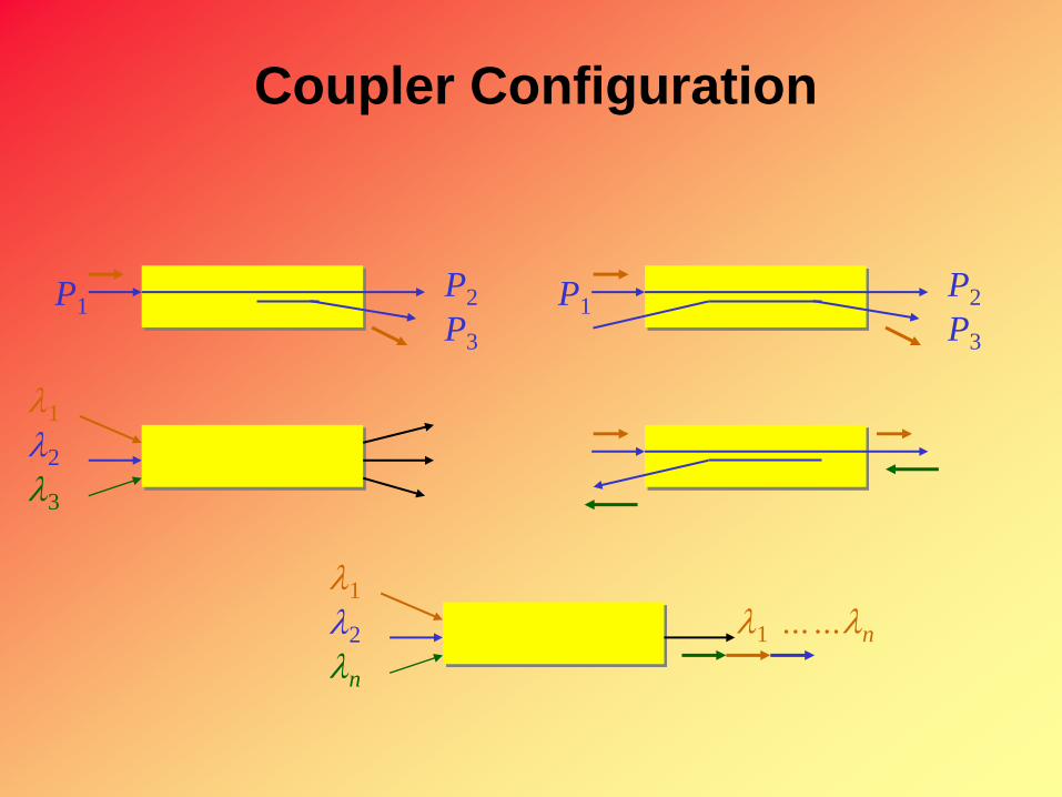
Coupler Configuration
P1P2
P3
P1P2
P3
l1
l2
l3
l1
l2
ln
l1 ……ln

Integrated Optics
20

WDM DEMUX TECHNOLOGIES
Interference filters
• Interference filters for DWDM
• Diffraction gratings
Fiber Bragg gratings
Mach-Zehnder interferometers
Planar waveguide arrays
21

INTERFERENCE FILTERS FOR WDM
Multiple filters needed for WDM
Pick-off one wavelength at a time
Pick bands, then individual wavelengths
High resolution possible
Many components
Scalable in increments
22
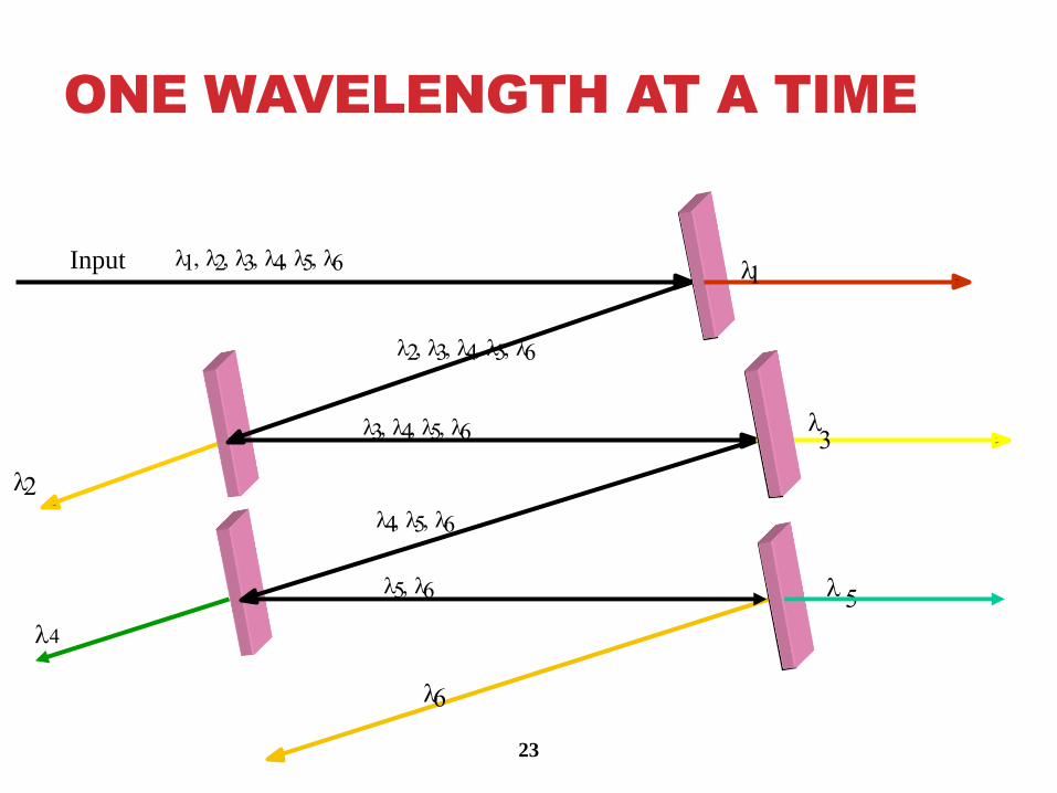
ONE WAVELENGTH AT A TIME
23
l1, l2, l3, l4, l5, l6 l1
l2, l3, l4, l5, l6
l2
l3, l4, l5, l6 l3
l4, l5, l6
l4
l5, l6 l 5
l6
Input
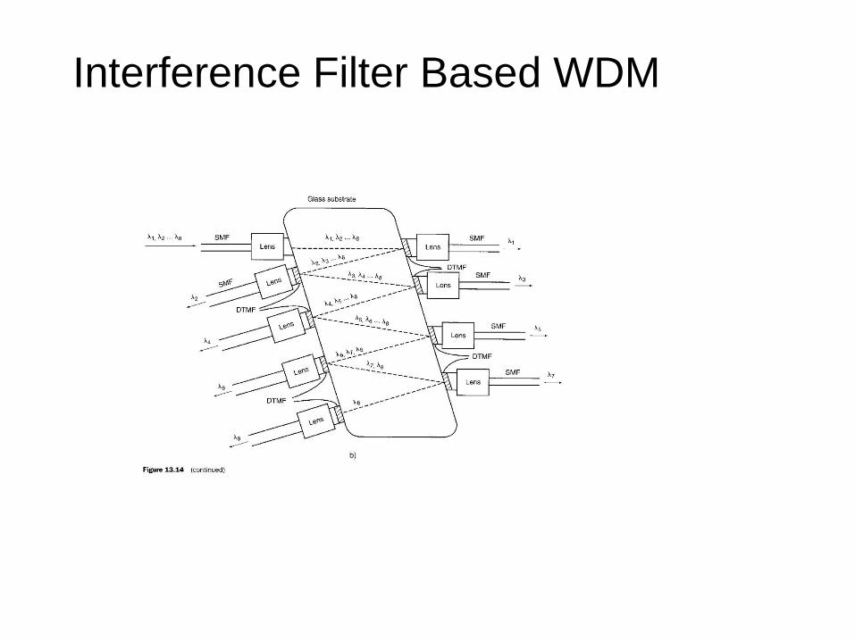
Interference Filter Based WDM

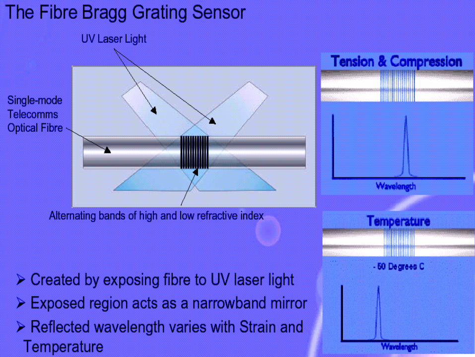
FIBER BRAGG GRATINGS
Function analogous to interference filters
Zones of high refractive index scatter light
Selectively reflect one wavelength
• Transmit other wavelengths
Like filters, can be grouped to drop one wavelength at a time
Require an optical circulator
Fiber components
25

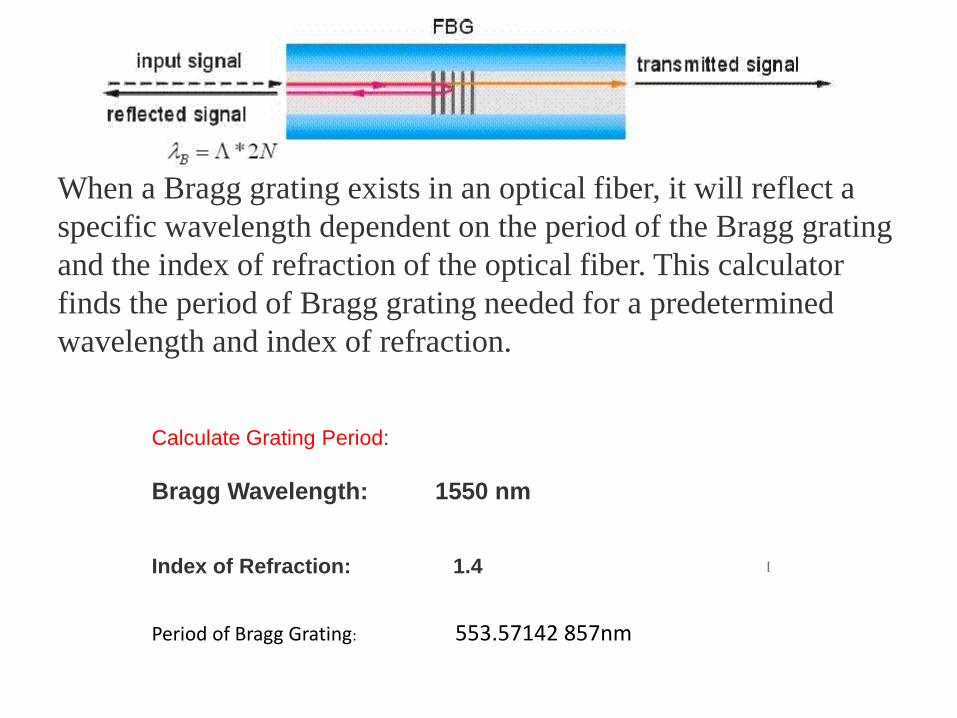
Calculate Grating Period:
Bragg Wavelength: 1550 nm
Index of Refraction: 1.4 [
Period of Bragg Grating: 553.57142 857nm
When a Bragg grating exists in an optical fiber, it will reflect a
specific wavelength dependent on the period of the Bragg grating
and the index of refraction of the optical fiber. This calculator
finds the period of Bragg grating needed for a predetermined
wavelength and index of refraction.

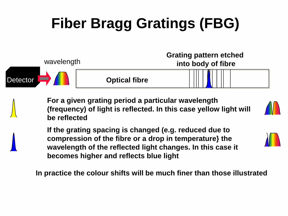
wavelength
For a given grating period a particular wavelength
(frequency) of light is reflected. In this case yellow light will
be reflected
If the grating spacing is changed (e.g. reduced due to
compression of the fibre or a drop in temperature} the
wavelength of the reflected light changes. In this case it
becomes higher and reflects blue light
In practice the colour shifts will be much finer than those illustrated
Optical fibre
Grating pattern etched
into body of fibre
Detector
Fiber Bragg Gratings (FBG)

ADD/DROP WITH FIBER GRATING
31
Fiber Bragg grating
Reflects l8
Multichannel input
Reflected channel only
Optical
circulator
l1-l7
l1-l8
l1-l8
l8
l8l8
l1-l8
Transmits
Circulator directs reflected
light to third port

With DWDM the aggregate optical power on a single fibre is
high
With the use of amplifiers the optical power level can rise to
point where non-linear effects occur:
Four wave mixing (FWM): spurious components are created
interfering with wanted signals
Stimulated Raman Scattering (SRS)
Non-linear effects are dependent on optical power levels,
channels spacing etc:
DWDM PROBLEMS

INITIAL WDM SIGNAL
33
All channels roughly equal power

FINAL WDM SIGNAL
34
After a series of amplifiers
Signal to noise reduced
Some channels stronger than others

GAIN TILT AND GAIN
SLOPE

OPTICAL AMPLIFIERS
1/8/2015 36
J.K.Chhabra, Scientist, CSIO
Chandigarh

Optical Amplifier
Pout = GPinPin
• EDFA amplifiers
• Separate amplifiers for C-band and L-band
• Source of optical noise
• Simple
G

EDFA

Erbium Doped Fiber Amplifier
“Simple” device consisting of four parts:
• Erbium-doped fiber
• An optical pump (to invert the population).
• A coupler
• An isolator to cut off backpropagating noise
Isolator Coupler IsolatorCoupler
Erbium-Doped
Fiber (10–50m)
Pump
Laser
Pump
Laser


Bidirectional Transmission using
WDM
Source: Master 7_4

TRANSMITTE
R
A
Fibre, connectors and splices
RECEIVER
B
TRANSMITTE
R
B
RECEIVER
A
WDM
Mux/Demux
WDM
Mux/Demux
1330 nm
1550 nm
Transmitter A communicates with Receiver A using a signal on 1330 nm
Transmitter B communicates with Receiver B using a signal on 1550 nm
WDM Mux/Demux filters out the wanted wavelength so that for example
Receiver A only receives a 1330 nm signal
Bi-directional Transmission using
WDM

To avoid interference red and blue bands must be separated
This separation is called a "guard band"
Guard band is typically about 5 nm
Guard band wastes spectral space, disadvantage of bi-directional
DWDM
Blue
channel
band
Red
channel
band
1528 nm 1560 nm
G
u
a
r
d
B
a
n
d
The need for a Guard Band

WDM SUMMARY
Several viable technologies
Can be used in conjunction
• Interleavers for fine resolution
• Filters for coarser resolution
Each has attractions for some applications
Costs hard to pin down
A real technology horse race
45

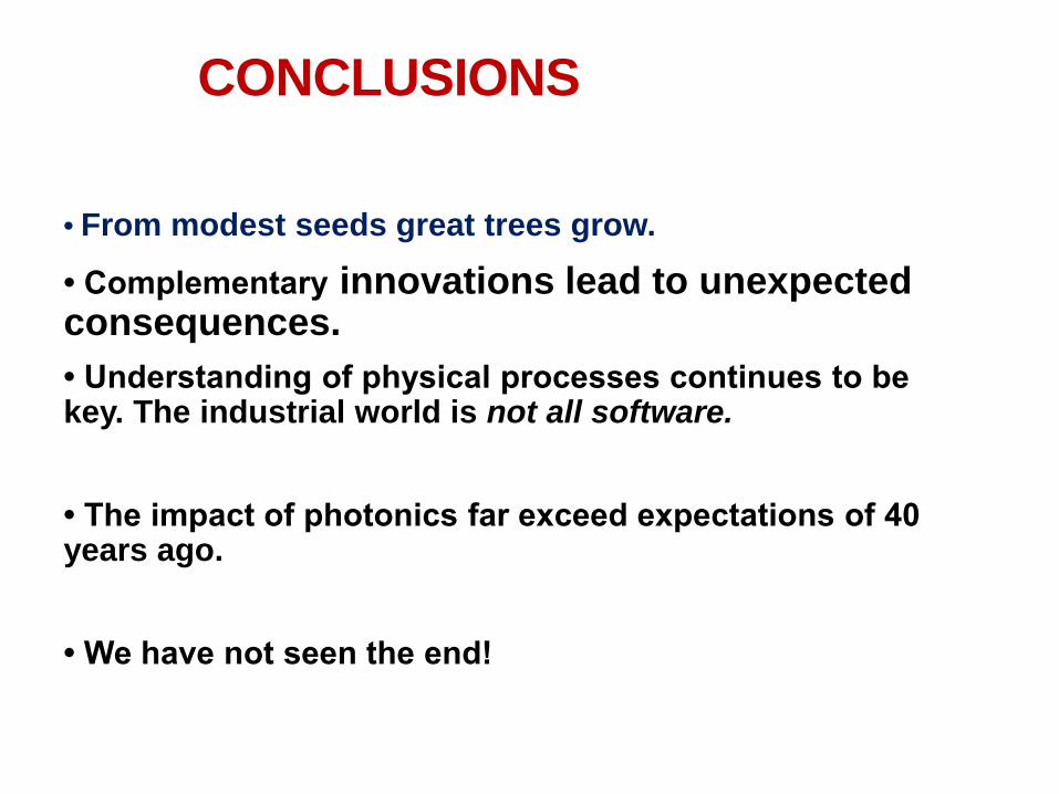
CONCLUSIONS
• From modest seeds great trees grow.
• Complementary innovations lead to unexpected consequences.
• Understanding of physical processes continues to be key. The industrial world is not all software.
• The impact of photonics far exceed expectations of 40 years ago.
• We have not seen the end!

Thank you