WDM and DWDM Multiplexing
113
Source: Master 7_4 WDM and DWDM Multiplexing
-
Upload
tonzkosgei -
Category
Documents
-
view
44 -
download
2
Transcript of WDM and DWDM Multiplexing
Source: Master 7_4
WDM and DWDM Multiplexing
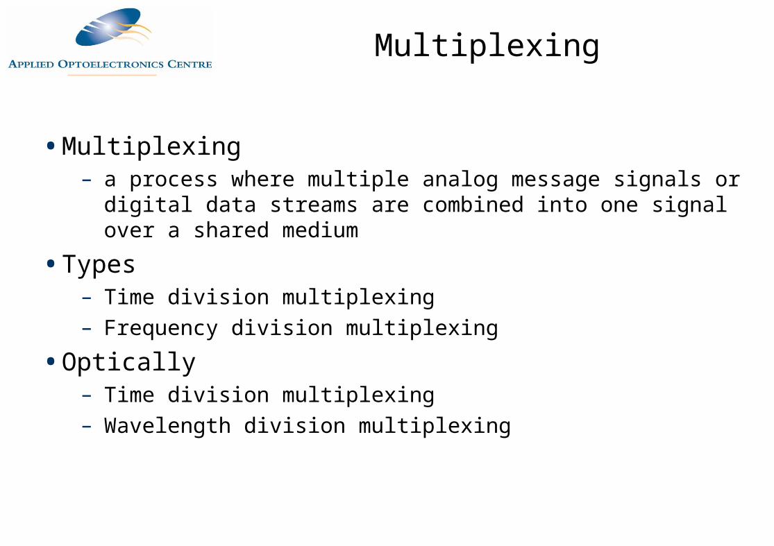
Multiplexing
• Multiplexing– a process where multiple analog message signals or digital data
streams are combined into one signal over a shared medium
• Types– Time division multiplexing– Frequency division multiplexing
• Optically– Time division multiplexing– Wavelength division multiplexing
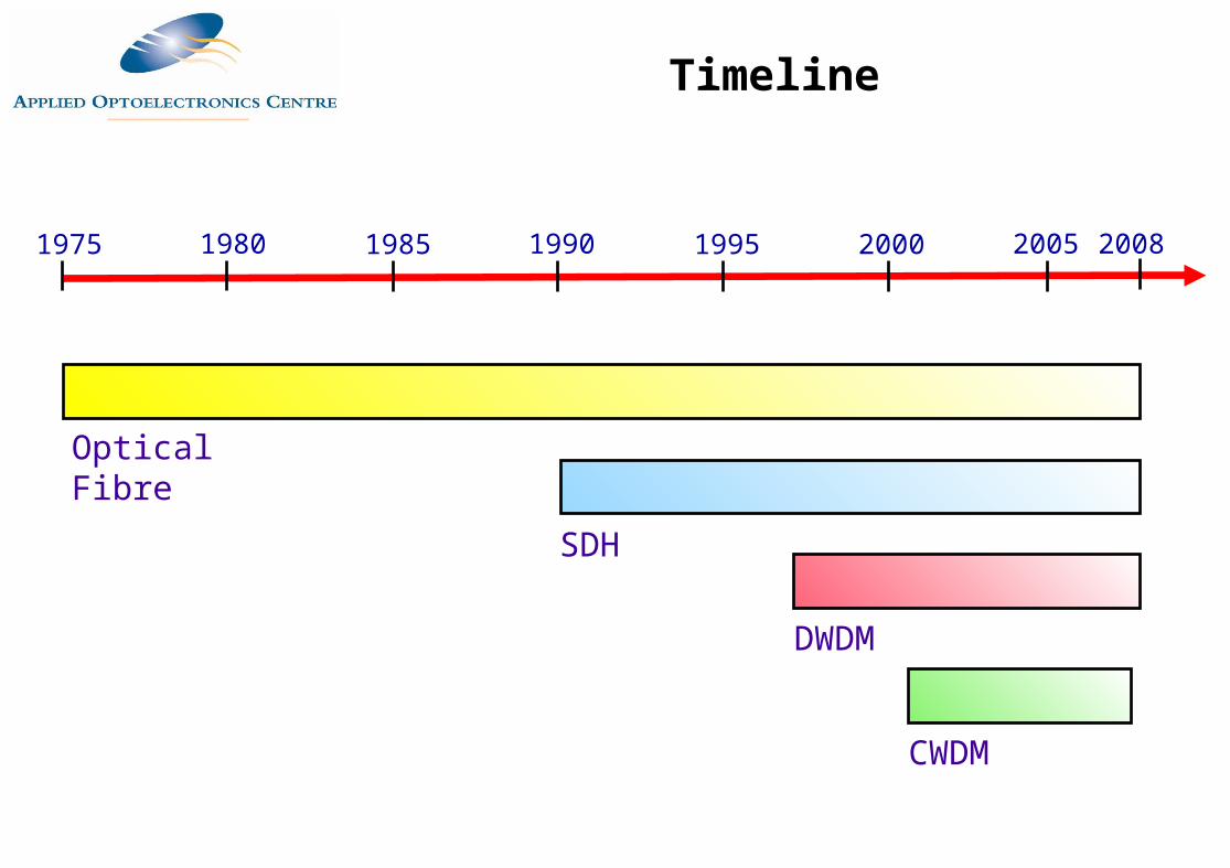
1975 1980 1985 1990 1995 2000
Optical Fibre
SDH
DWDM
Timeline
2005
CWDM
2008
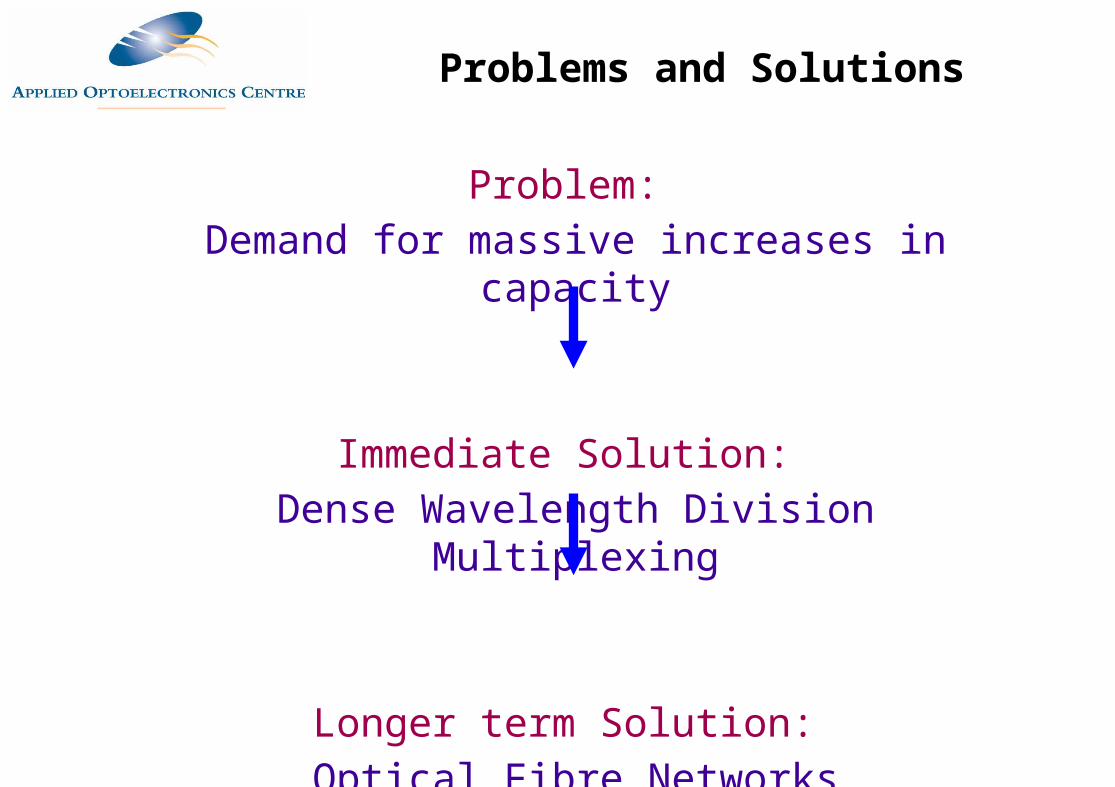
Problem: Demand for massive increases in capacity
Immediate Solution: Dense Wavelength Division Multiplexing
Longer term Solution: Optical Fibre Networks
Problems and Solutions
Wavelength Division Multiplexing
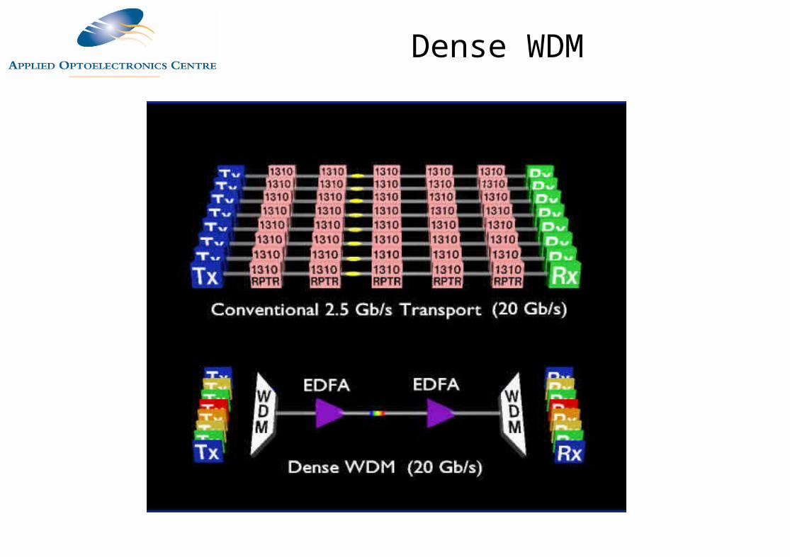
Dense WDM
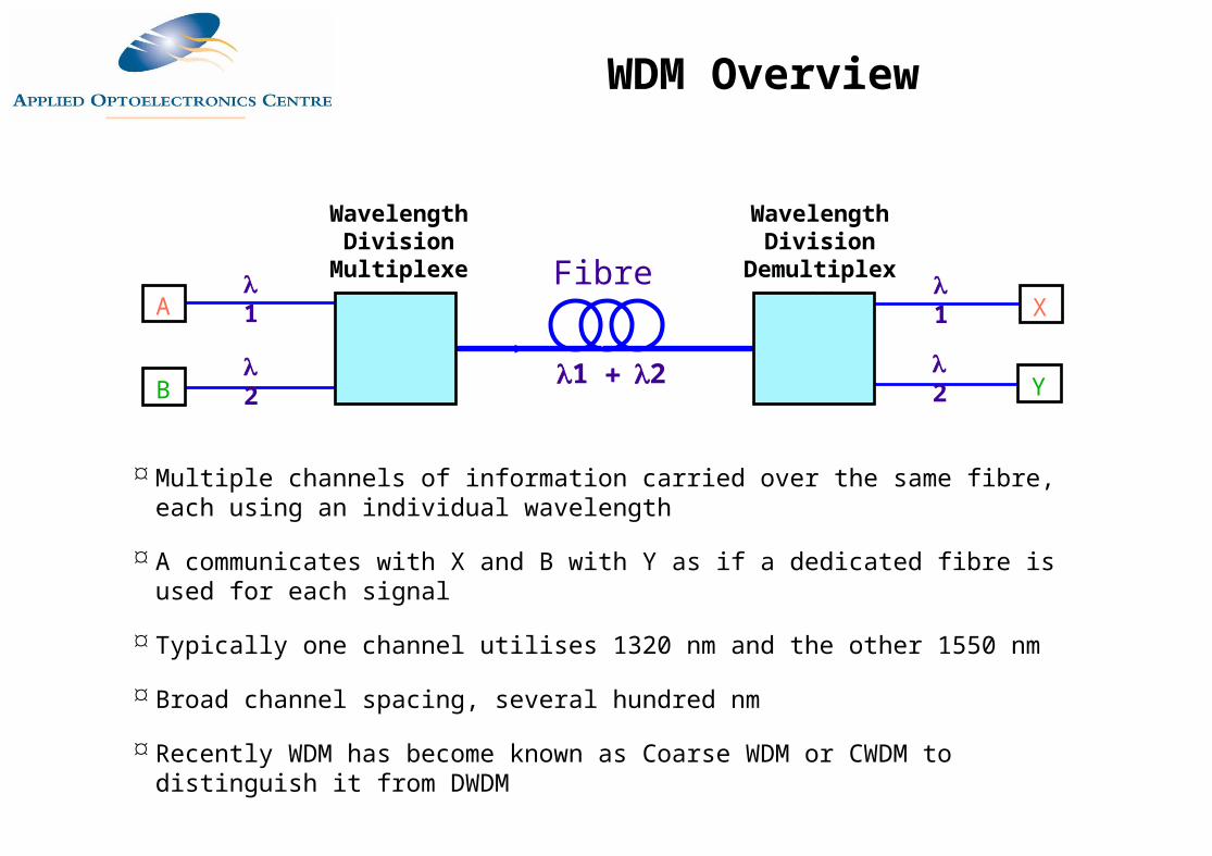
Multiple channels of information carried over the same fibre, each using an individual wavelength
A communicates with X and B with Y as if a dedicated fibre is used for each signal
Typically one channel utilises 1320 nm and the other 1550 nm
Broad channel spacing, several hundred nm
Recently WDM has become known as Coarse WDM or CWDM to distinguish it from DWDM
Wavelength Division
Multiplexer
Wavelength Division
Demultiplexer1
A
2B
1X
2Y1 2
Fibre
WDM Overview
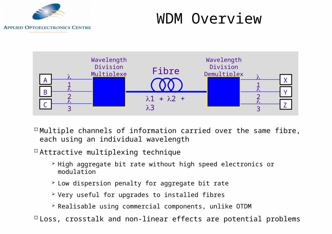
Multiple channels of information carried over the same fibre, each using an individual wavelength
Attractive multiplexing technique High aggregate bit rate without high speed electronics or modulation Low dispersion penalty for aggregate bit rate Very useful for upgrades to installed fibres Realisable using commercial components, unlike OTDM
Loss, crosstalk and non-linear effects are potential problems
Wavelength Division
Multiplexer
Wavelength Division
Demultiplexer1A2
3B
C
1 X2
3Y
Z1 2 + 3
Fibre
WDM Overview
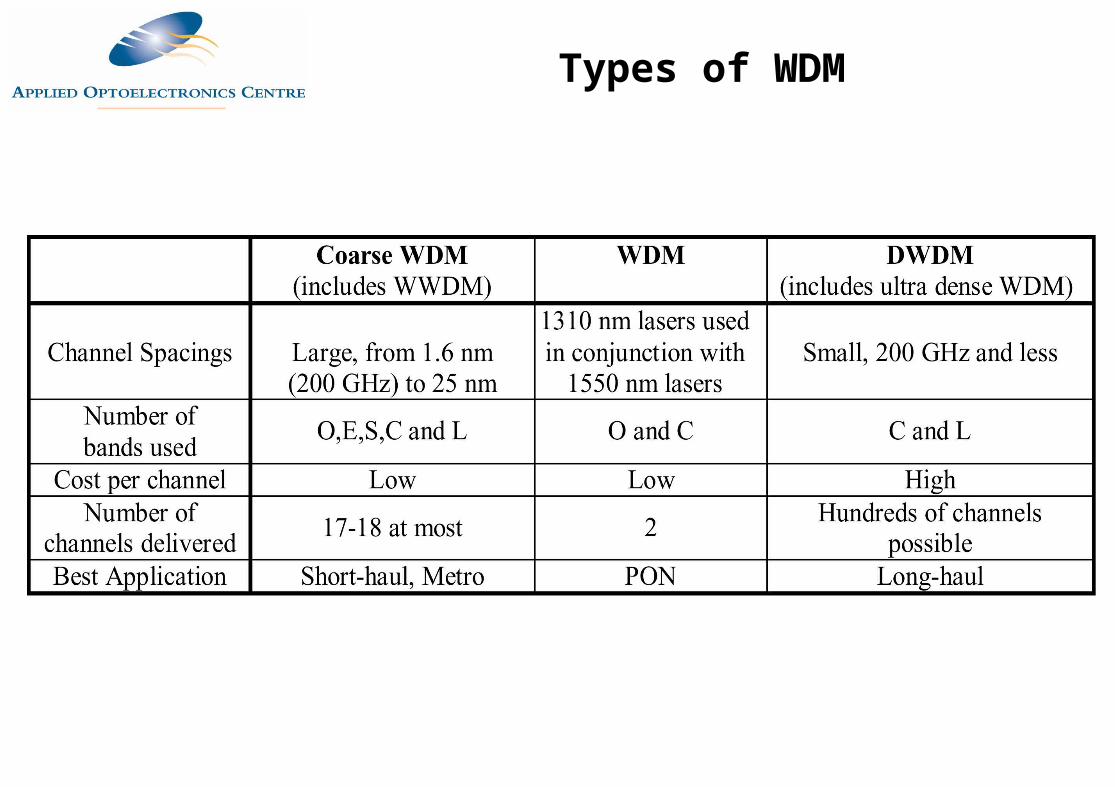
Types of WDM
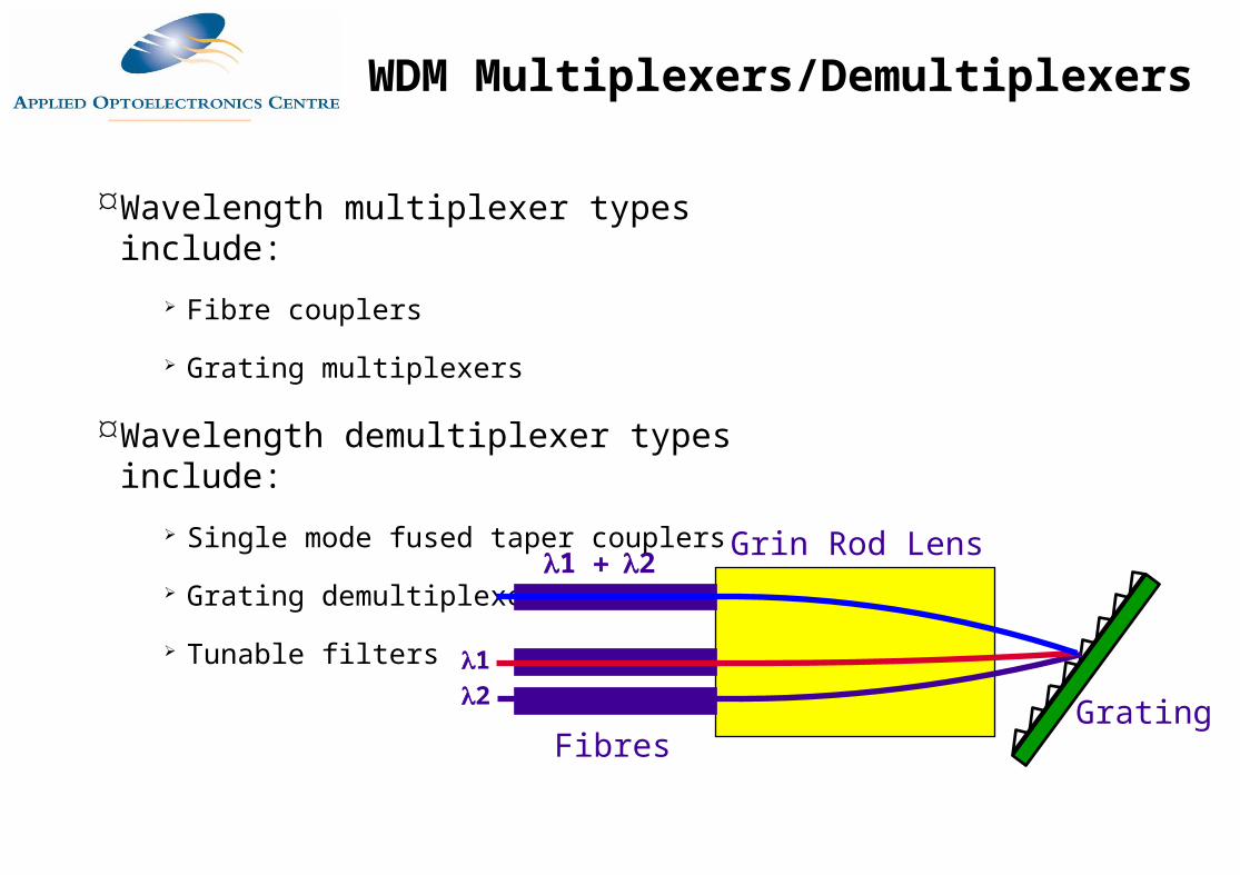
Wavelength multiplexer types include: Fibre couplers
Grating multiplexers
Wavelength demultiplexer types include: Single mode fused taper couplers
Grating demultiplexers
Tunable filtersGrating
Multiplexer Demultiplex
erGrating
Grin Rod Lens
Fibres
12
1 2
WDM Multiplexers/Demultiplexers
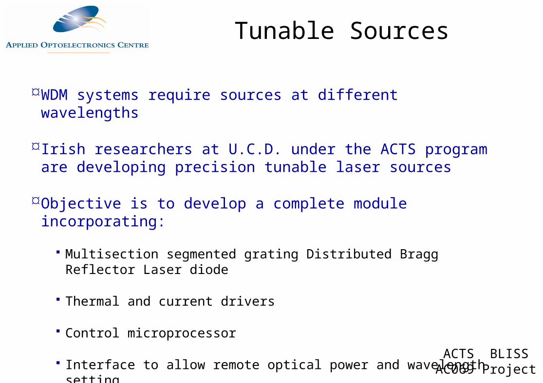
WDM systems require sources at different wavelengths
Irish researchers at U.C.D. under the ACTS program are developing precision tunable laser sources
Objective is to develop a complete module incorporating:
Multisection segmented grating Distributed Bragg Reflector Laser diode
Thermal and current drivers
Control microprocessor
Interface to allow remote optical power and wavelength setting
ACTS BLISS AC069 Project
Tunable Sources
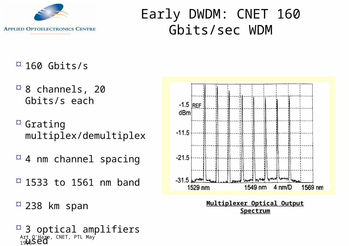
Multiplexer Optical Output Spectrum
Art O'Hare, CNET, PTL May 1996
160 Gbits/s
8 channels, 20 Gbits/s each
Grating multiplex/demultiplex
4 nm channel spacing
1533 to 1561 nm band
238 km span
3 optical amplifiers used
Early DWDM: CNET 160 Gbits/sec WDM
Buffered Fibre on Reels
Optical Transmitters
Early DWDM: CNET WDM Experimental Setup
Dense Wavelength Division Multiplexing
Multiple channels of information carried over the same fibre, each using an individual wavelength
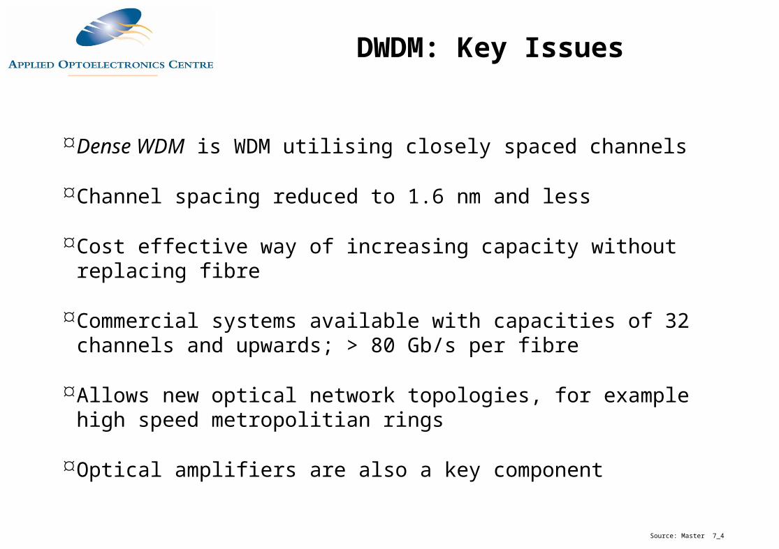
Dense WDM is WDM utilising closely spaced channels
Channel spacing reduced to 1.6 nm and less
Cost effective way of increasing capacity without replacing fibre
Commercial systems available with capacities of 32 channels and upwards; > 80 Gb/s per fibre
Wavelength Division
Multiplexer
Wavelength Division
Demultiplexer1
A2
3B
C
1X
2
3Y
Z1 2 + 3
Fibre
Dense Wavelength Division Multiplexing
Multiple channels of information carried over the same fibre, each using an individual wavelength
Unlike CWDM channels are much closer together
Transmitter T1 communicates with Receiver R1 as if connected by a
dedicated fibre as does T2 and R2 and so on
Wavelength Division
Multiplexer
Wavelength Division
Demultiplexer1
T12
N
T2
TN
1R1
2
N
R2
RN
Source: Master 7_4
1 2 ... N
Fibre
Simple DWDM System
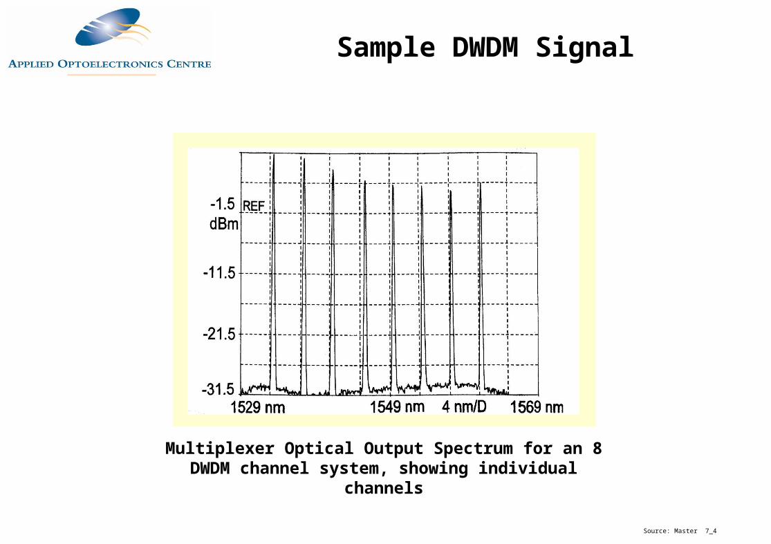
Multiplexer Optical Output Spectrum for an 8 DWDM channel system, showing individual channels
Source: Master 7_4
Sample DWDM Signal
Dense WDM is WDM utilising closely spaced channels
Channel spacing reduced to 1.6 nm and less
Cost effective way of increasing capacity without replacing fibre
Commercial systems available with capacities of 32 channels and upwards; > 80 Gb/s per fibre
Allows new optical network topologies, for example high speed metropolitian rings
Optical amplifiers are also a key component
Source: Master 7_4
DWDM: Key Issues
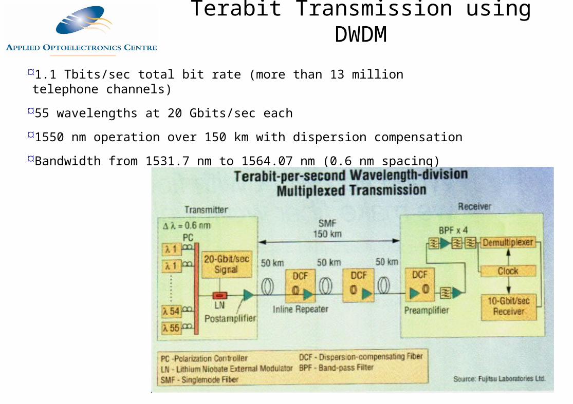
1.1 Tbits/sec total bit rate (more than 13 million telephone channels)
55 wavelengths at 20 Gbits/sec each
1550 nm operation over 150 km with dispersion compensation
Bandwidth from 1531.7 nm to 1564.07 nm (0.6 nm spacing)
Terabit Transmission using DWDM

Expansion Options
Install more fibre New fibre is expensive to install (Euro 100k + per km)
Fibre routes require a right-of-way
Additional regenerators and/or amplifiers may be required
Install more SDH network elements over dark fibre Additional regenerators and/or amplifiers may be required
More space needed in buildings
Capacity Expansion Options (I)
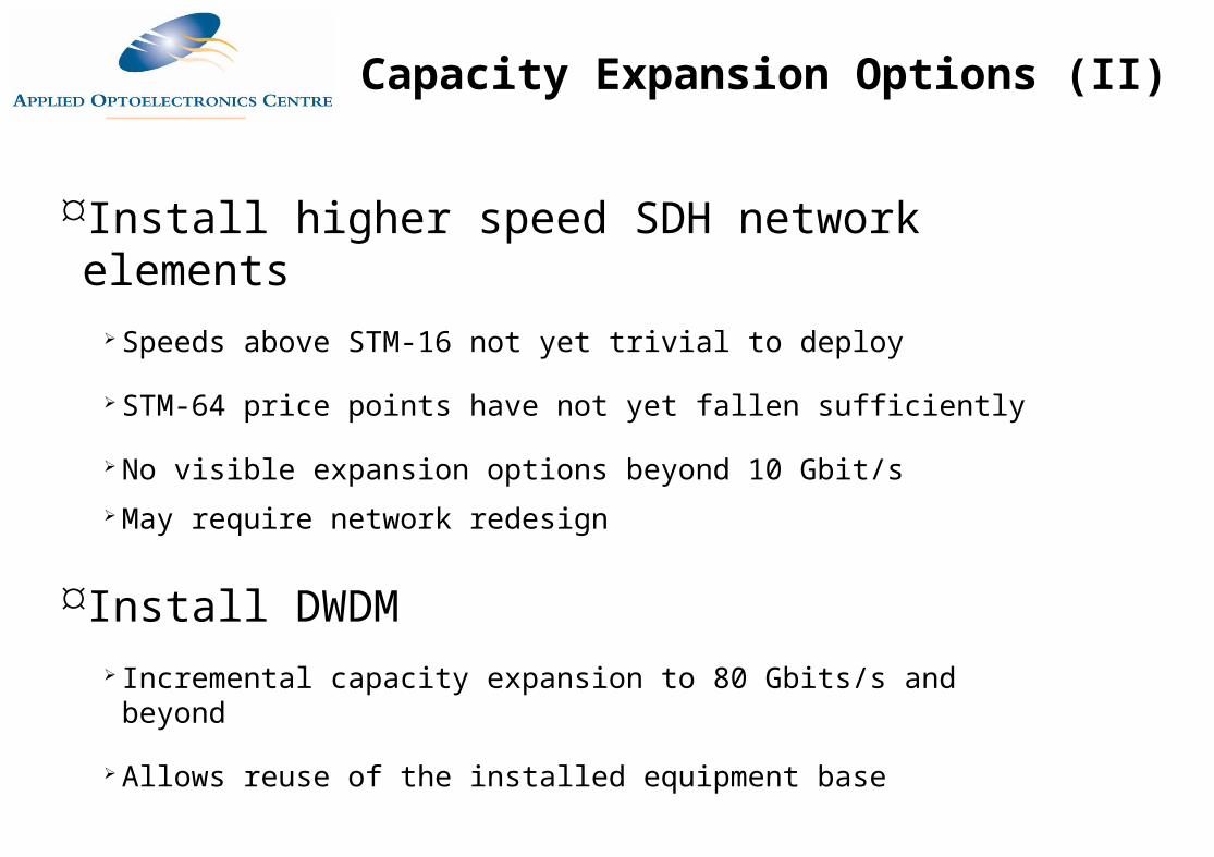
Install higher speed SDH network elements Speeds above STM-16 not yet trivial to deploy
STM-64 price points have not yet fallen sufficiently
No visible expansion options beyond 10 Gbit/s May require network redesign
Install DWDM Incremental capacity expansion to 80 Gbits/s and beyond
Allows reuse of the installed equipment base
Capacity Expansion Options (II)
DWDM Advantages and Disadvantages
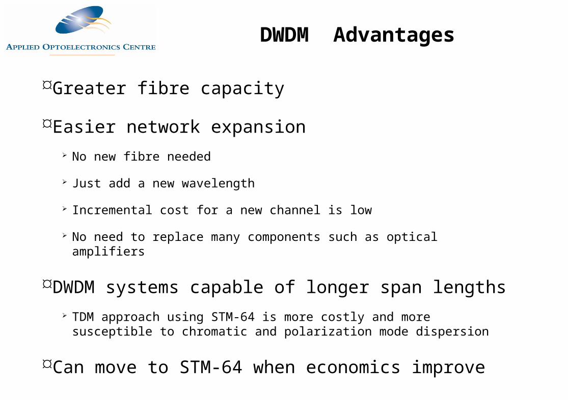
Greater fibre capacity
Easier network expansion No new fibre needed
Just add a new wavelength
Incremental cost for a new channel is low
No need to replace many components such as optical amplifiers
DWDM systems capable of longer span lengths TDM approach using STM-64 is more costly and more susceptible to chromatic
and polarization mode dispersion
Can move to STM-64 when economics improve
DWDM Advantages
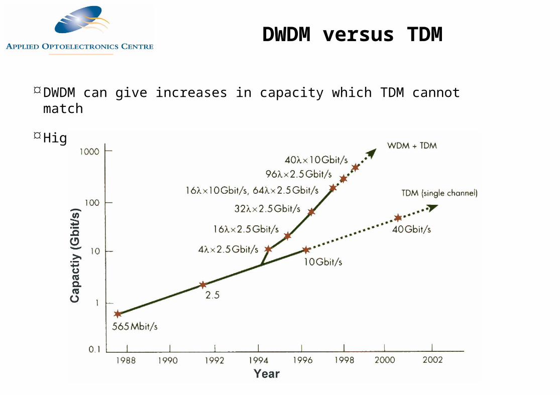
DWDM can give increases in capacity which TDM cannot match
Higher speed TDM systems are very expensive
DWDM versus TDM
Not cost-effective for low channel numbers Fixed cost of mux/demux, transponder, other system components
Introduces another element, the frequency domain, to network design and management
SONET/SDH network management systems not well equipped to handle DWDM topologies
DWDM performance monitoring and protection methodologies developing
DWDM Disadvantages
DWDM installed on a large scale first in the USA larger proportion of longer >1000km links
Earlier onset of "fibre exhaust" (saturation of capacity) in 1995-96
Market is gathering momentum in Europe Increase in date traffic has existing operators deploying DWDM
New entrants particularly keen to use DWDM in Europe Need a scaleable infrastructure to cope with demand as it grows
DWDM allows incremental capacity increases
DWDM is viewed as an integral part of a market entry strategy
DWDM: Commercial Issues
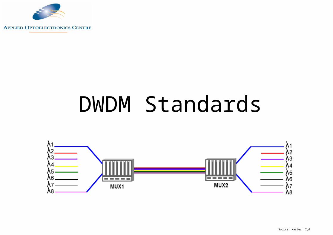
DWDM Standards
Source: Master 7_4
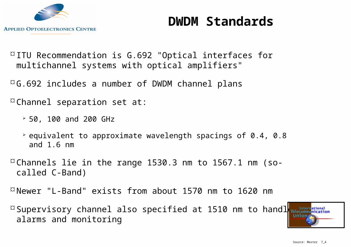
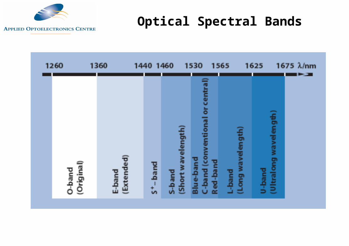
ITU Recommendation is G.692 "Optical interfaces for multichannel systems with optical amplifiers"
G.692 includes a number of DWDM channel plans
Channel separation set at:
50, 100 and 200 GHz
equivalent to approximate wavelength spacings of 0.4, 0.8 and 1.6 nm
Channels lie in the range 1530.3 nm to 1567.1 nm (so-called C-Band)
Newer "L-Band" exists from about 1570 nm to 1620 nm
Supervisory channel also specified at 1510 nm to handle alarms and monitoring
Source: Master 7_4
DWDM Standards
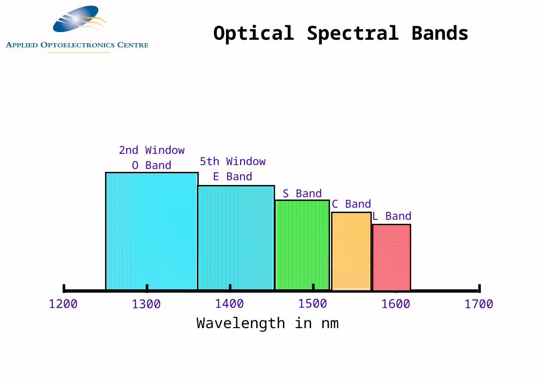
Wavelength in nm1200 17001300 1400 16001500
S BandC Band
L Band
5th WindowE Band
2nd WindowO Band
Optical Spectral Bands
Optical Spectral Bands
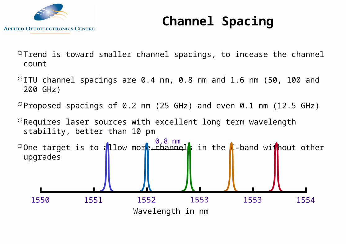
Trend is toward smaller channel spacings, to incease the channel count
ITU channel spacings are 0.4 nm, 0.8 nm and 1.6 nm (50, 100 and 200 GHz)
Proposed spacings of 0.2 nm (25 GHz) and even 0.1 nm (12.5 GHz)
Requires laser sources with excellent long term wavelength stability, better than 10 pm
One target is to allow more channels in the C-band without other upgrades
Wavelength in nm1550 15541551 1552 15531553
0.8 nm
Channel Spacing
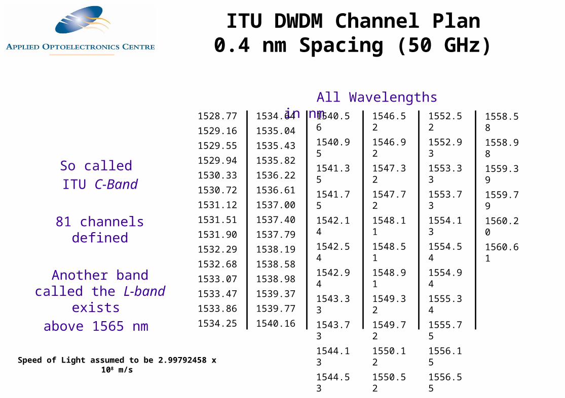
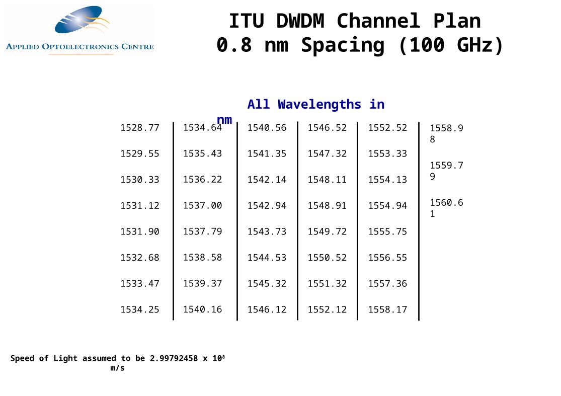
Speed of Light assumed to be 2.99792458 x 10⁸ m/s
All Wavelengths in nm1552.521552.931553.331553.731554.131554.541554.941555.341555.751556.151556.551556.961557.361557.771558.17
1546.521546.921547.321547.721548.111548.511548.911549.321549.721550.121550.521550.921551.321551.721552.12
1540.561540.951541.351541.751542.141542.541542.941543.331543.731544.131544.531544.921545.321545.721546.12
1534.641535.041535.431535.821536.221536.611537.001537.401537.791538.191538.581538.981539.371539.771540.16
1528.771529.161529.551529.941530.331530.721531.121531.511531.901532.291532.681533.071533.471533.861534.25
1558.581558.981559.391559.791560.201560.61
So called ITU C-Band
81 channels defined
Another band called the L-band exists above 1565 nm
ITU DWDM Channel Plan0.4 nm Spacing (50 GHz)
Speed of Light assumed to be 2.99792458 x 10⁸ m/s
1552.52
1553.33
1554.13
1554.94
1555.75
1556.55
1557.36
1558.17
1546.52
1547.32
1548.11
1548.91
1549.72
1550.52
1551.32
1552.12
1540.56
1541.35
1542.14
1542.94
1543.73
1544.53
1545.32
1546.12
1534.64
1535.43
1536.22
1537.00
1537.79
1538.58
1539.37
1540.16
1528.77
1529.55
1530.33
1531.12
1531.90
1532.68
1533.47
1534.25
1558.98
1559.79
1560.61
All Wavelengths in nm
ITU DWDM Channel Plan 0.8 nm Spacing (100 GHz)
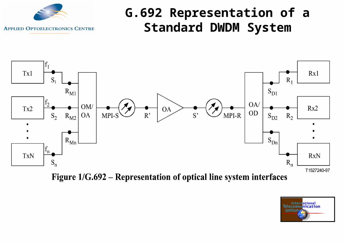
G.692 Representation of a Standard DWDM System
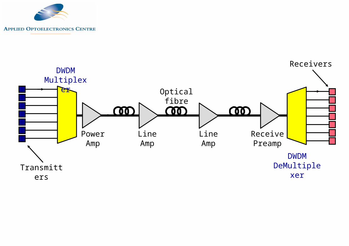
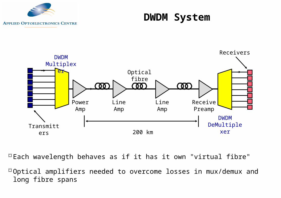
DWDM Components
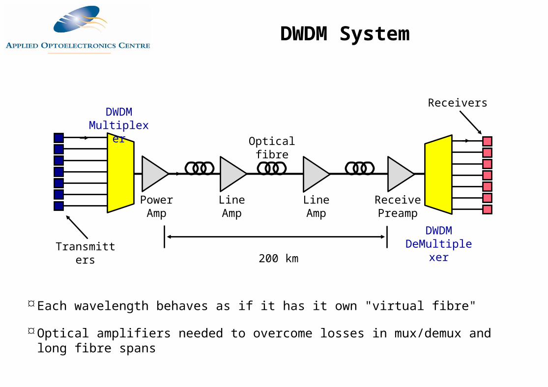
Transmitters
DWDM Multiplexer
Power Amp
Line Amp
Line Amp
Receive Preamp
200 km
DWDM DeMultiplexer
Each wavelength behaves as if it has it own "virtual fibre"
Optical amplifiers needed to overcome losses in mux/demux and long fibre spans
Receivers
Optical fibre
DWDM System
Transmitters
DWDM Multiplexer
Power Amp
Line Amp
Line Amp
Optical fibre
Receive Preamp
DWDM DeMultiplexer
Receivers
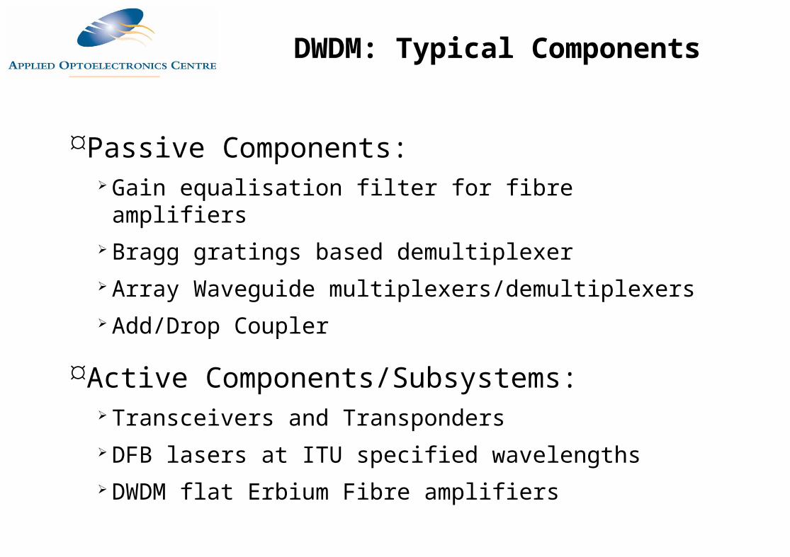
Passive Components: Gain equalisation filter for fibre amplifiers Bragg gratings based demultiplexer Array Waveguide multiplexers/demultiplexers Add/Drop Coupler
Active Components/Subsystems: Transceivers and Transponders DFB lasers at ITU specified wavelengths DWDM flat Erbium Fibre amplifiers
DWDM: Typical Components
Mux/Demuxes
n
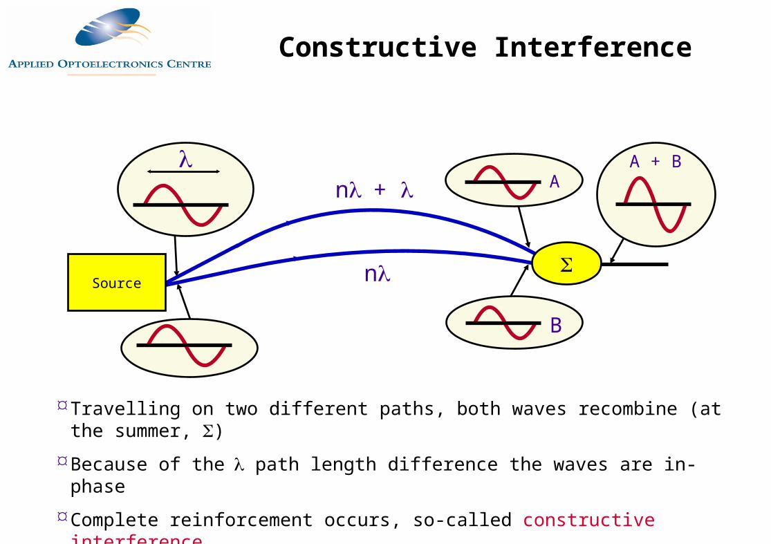
n+
Travelling on two different paths, both waves recombine (at the summer, )
Because of the path length difference the waves are in-phase
Complete reinforcement occurs, so-called constructive interference
Source
B
AA + B
Constructive Interference
n
n+ 0.5
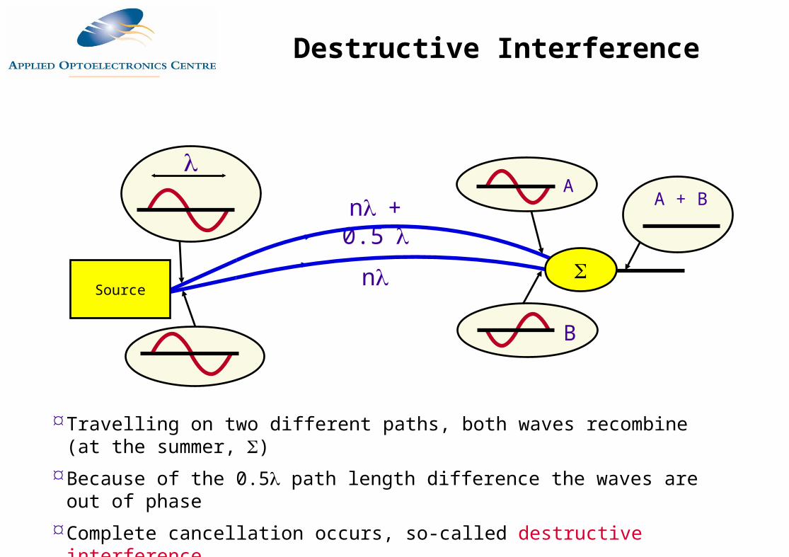
Travelling on two different paths, both waves recombine (at the summer, )Because of the 0.5 path length difference the waves are out of phaseComplete cancellation occurs, so-called destructive interference
Source
B
AA + B
Destructive Interference
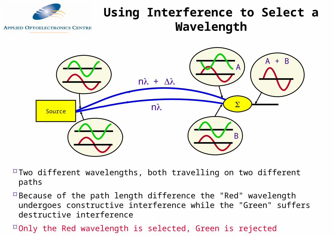
Two different wavelengths, both travelling on two different pathsBecause of the path length difference the "Red" wavelength undergoes constructive
interference while the "Green" suffers destructive interferenceOnly the Red wavelength is selected, Green is rejected
n
n+
Source
B
AA + B
Using Interference to Select a Wavelength
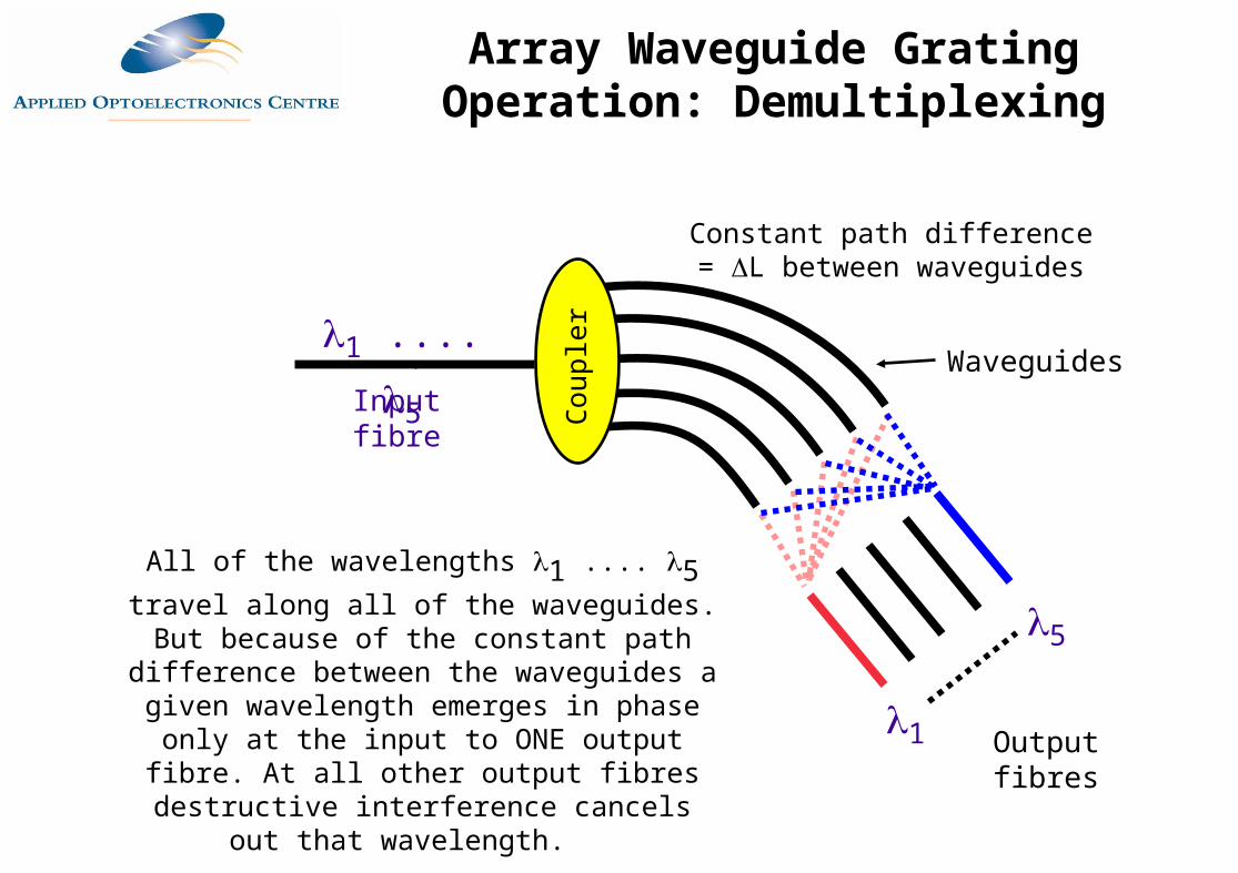
1 .... 5
Constant path difference = L between waveguides
Waveguides
Output fibres
Input fibre
All of the wavelengths 1 .... 5 travel along all of the waveguides. But because of the constant path difference between the waveguides a given wavelength emerges in phase only at the input to ONE output fibre. At all other output fibres
destructive interference cancels out that wavelength.
1
5
Cou
pler
Array Waveguide Grating Operation: Demultiplexing
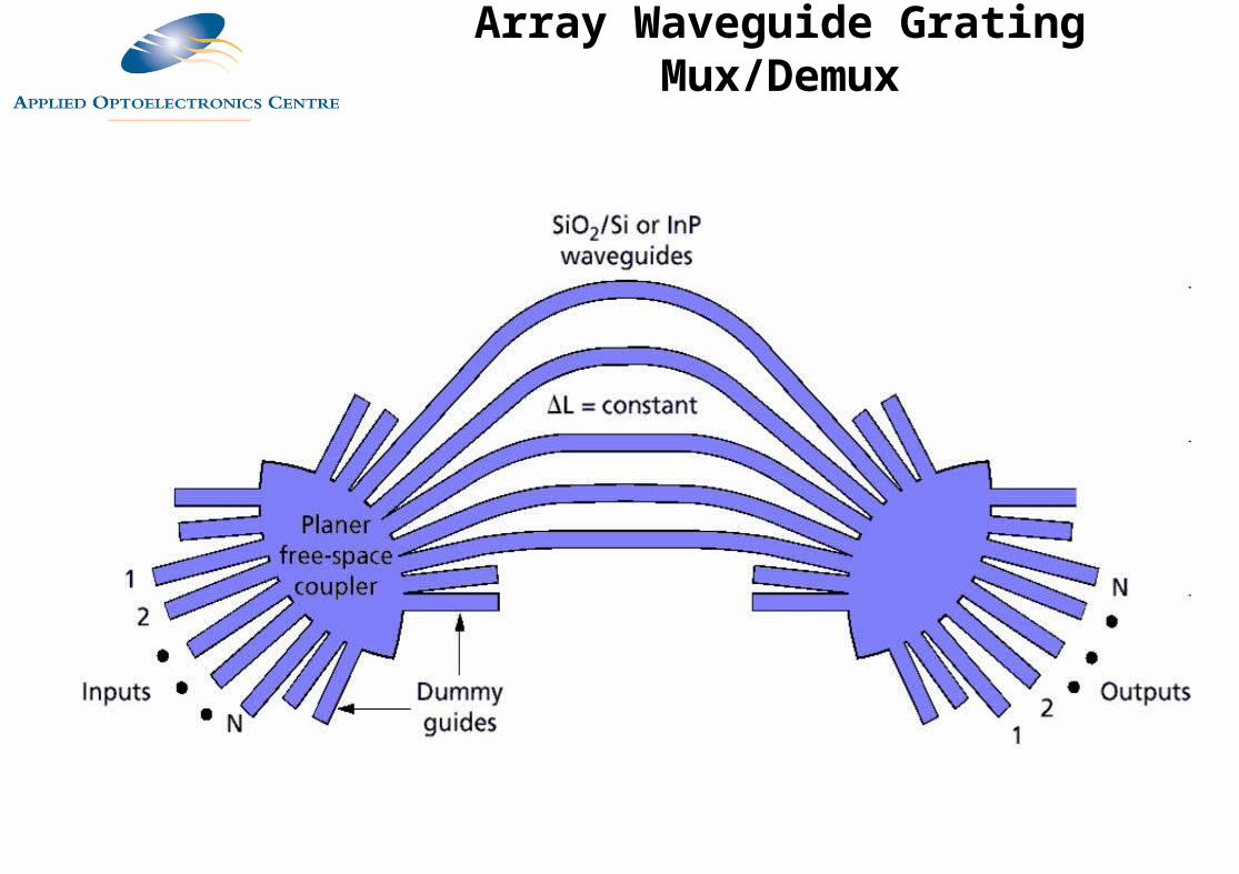
Array Waveguide Grating Mux/Demux
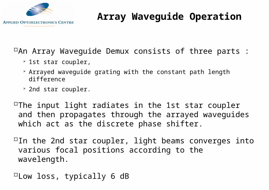
An Array Waveguide Demux consists of three parts : 1st star coupler, Arrayed waveguide grating with the constant path length difference 2nd star coupler.
The input light radiates in the 1st star coupler and then propagates through the arrayed waveguides which act as the discrete phase shifter.
In the 2nd star coupler, light beams converges into various focal positions according to the wavelength.
Low loss, typically 6 dB
Array Waveguide Operation
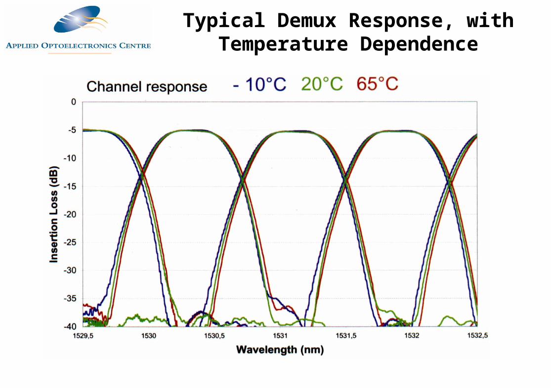
Typical Demux Response, with Temperature Dependence
DWDM Systems
Transmitters
DWDM Multiplexer
Power Amp
Line Amp
Line Amp
Receive Preamp
200 km
DWDM DeMultiplexer
Each wavelength behaves as if it has it own "virtual fibre"
Optical amplifiers needed to overcome losses in mux/demux and long fibre spans
Receivers
Optical fibre
DWDM System
Transmitters
DWDM Multiplexer
Power Amp
Line Amp
Receive Preamp
200 km
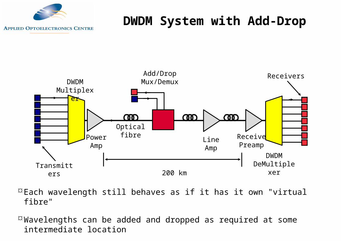
DWDM DeMultiplexer
Each wavelength still behaves as if it has it own "virtual fibre"
Wavelengths can be added and dropped as required at some intermediate location
ReceiversAdd/Drop Mux/Demux
Optical fibre
DWDM System with Add-Drop
Manufacturer&
System
Number of Channels
Channel Spacing
Channel Speeds
Maximum Bit RateTb/s
Nortel OPtera 1600 OLS
160 0.4 nm 2.5 or 10 Gb/s
1.6 Tbs/s
Lucent 40 2.5
Alcatel
MarconiPLT40/80/160
40/80/160 0.4, 0.8 nm 2.5 or 10 Gb/s
1.6 Tb/s
Typical DWDM Systems
Different systems suit national and metropolitian networks
Typical high-end systems currently provide: 40/80/160 channels Bit rates to 10 Gb/s with some 40 Gb/s Interfaces for SDH, PDH, ATM etc. Total capacity to 10 Tb/s + C + L and some S band operation
Systems available from NEC, Lucent, Marconi, Nortel, Alcatel, Siemens etc.
DWDM Performance as of 2008
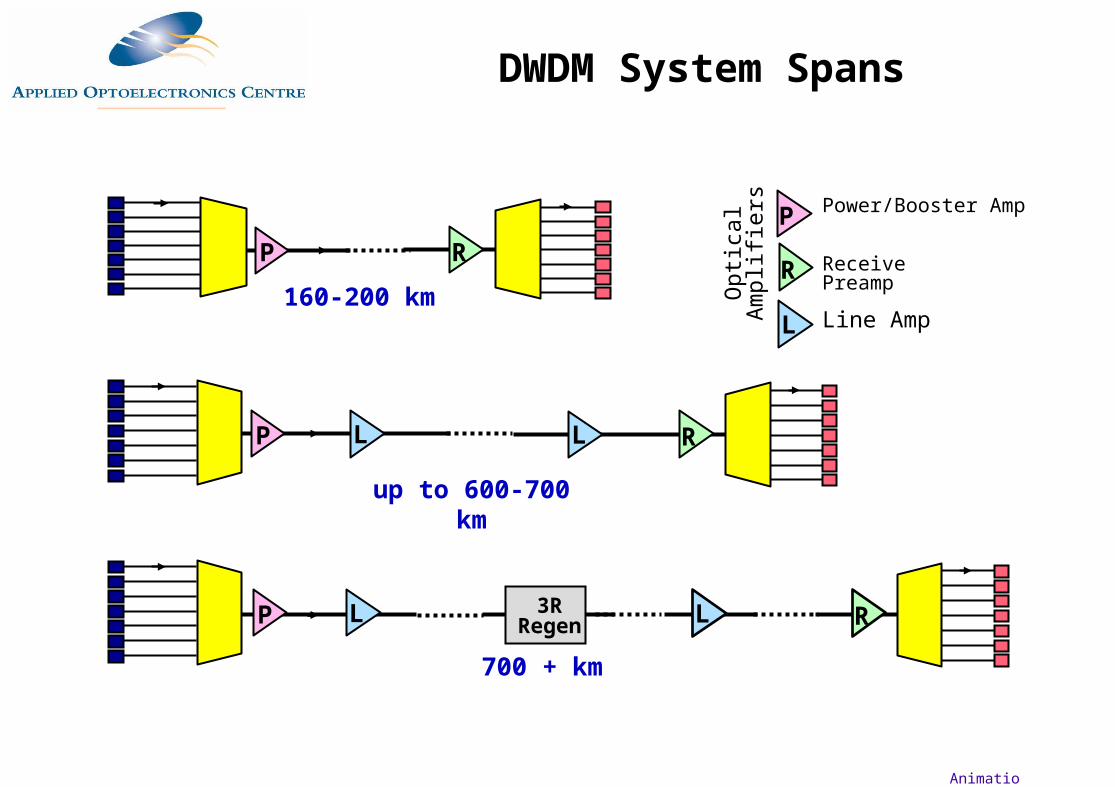
up to 600-700 km
L L RP
160-200 km
RP
700 + km
RL LP 3R Regen
Animation
Power/Booster Amp
Receive Preamp
Line Amp
P
R
L
Opt
ical
A
mpl
ifier
s
DWDM System Spans
ITU Recommendation is G.692 "Optical interfaces for multichannel systems with optical amplifiers"
G.692 includes a number of DWDM channel plans
Channel separation set at:
50, 100 and 200 GHz
equivalent to approximate wavelength spacings of 0.4, 0.8 and 1.6 nm
Channels lie in the range 1530.3 nm to 1567.1 nm (so-called C-Band)
Newer "L-Band" exists from about 1570 nm to 1620 nm
Supervisory channel also specified at 1510 nm to handle alarms and monitoring
DWDM Standards
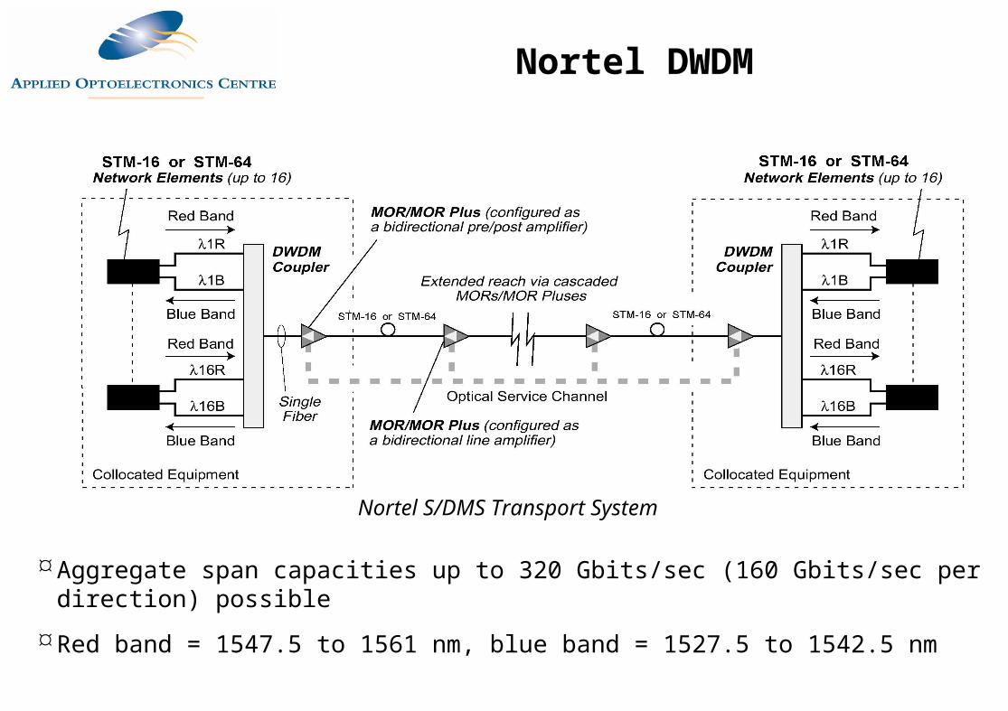
Aggregate span capacities up to 320 Gbits/sec (160 Gbits/sec per direction) possible
Red band = 1547.5 to 1561 nm, blue band = 1527.5 to 1542.5 nm
Nortel S/DMS Transport System
Nortel DWDM
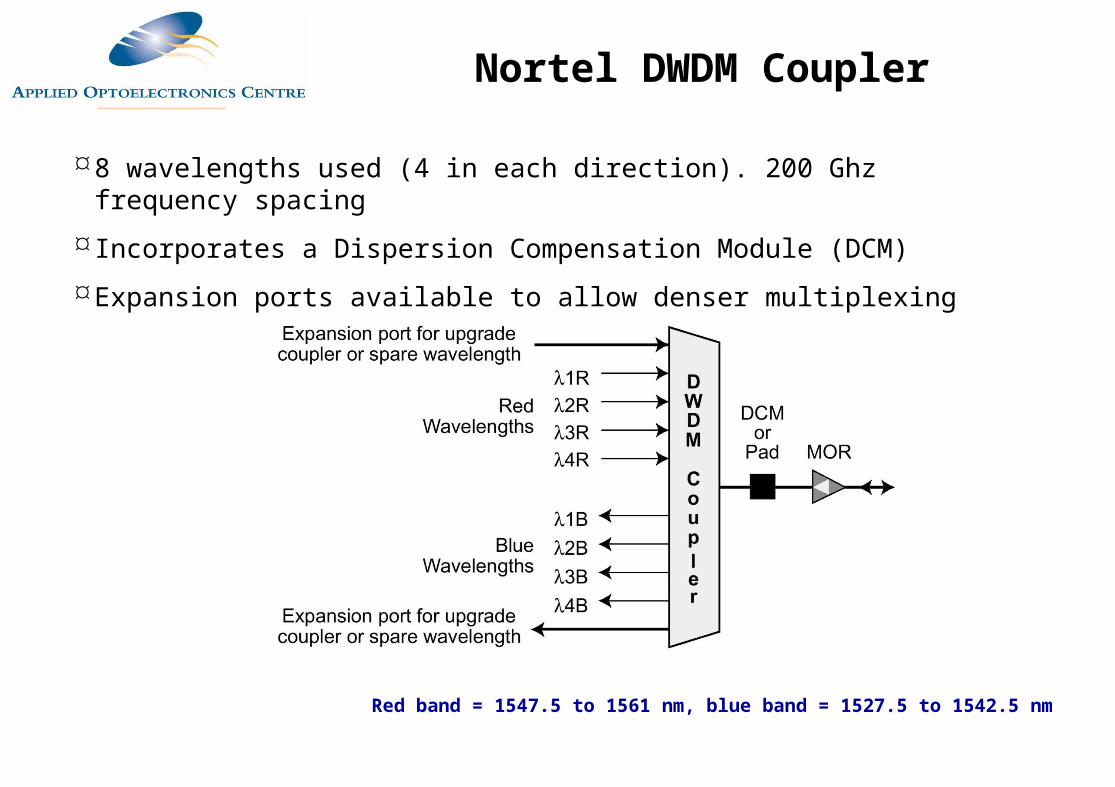
8 wavelengths used (4 in each direction). 200 Ghz frequency spacing
Incorporates a Dispersion Compensation Module (DCM)
Expansion ports available to allow denser multiplexing
Red band = 1547.5 to 1561 nm, blue band = 1527.5 to 1542.5 nm
Nortel DWDM Coupler
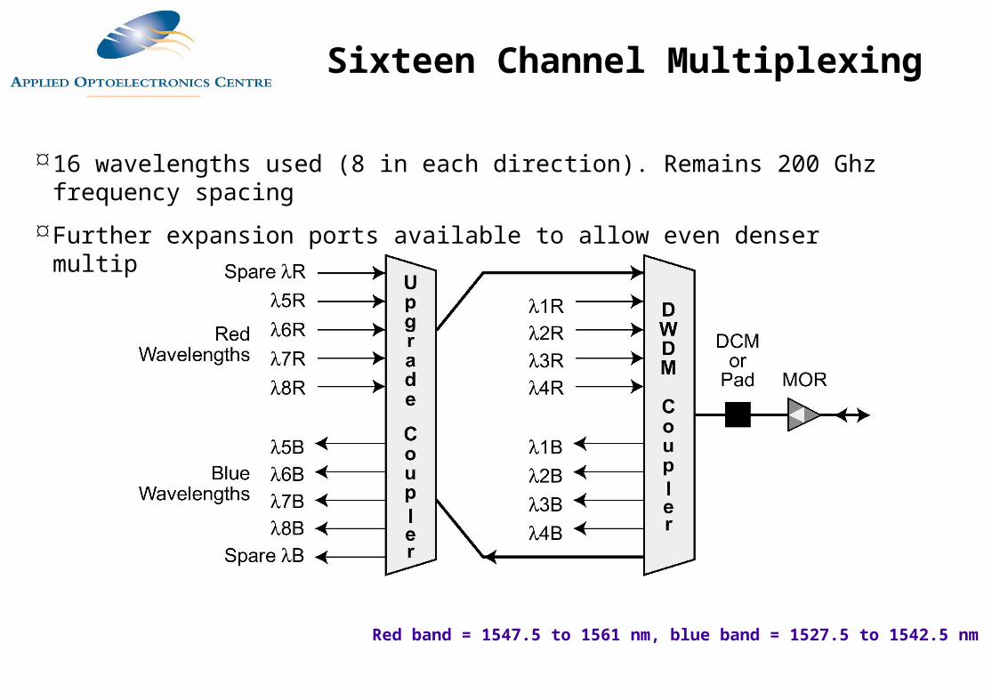
16 wavelengths used (8 in each direction). Remains 200 Ghz frequency spacing
Further expansion ports available to allow even denser multiplexing
Red band = 1547.5 to 1561 nm, blue band = 1527.5 to 1542.5 nm
Sixteen Channel Multiplexing
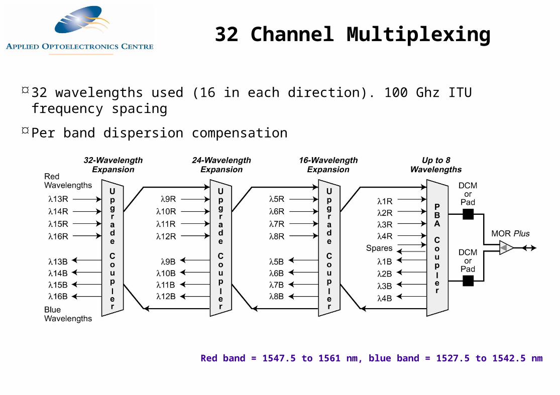
32 wavelengths used (16 in each direction). 100 Ghz ITU frequency spacing
Per band dispersion compensation
Red band = 1547.5 to 1561 nm, blue band = 1527.5 to 1542.5 nm
32 Channel Multiplexing
DWDM Transceivers and Transponders
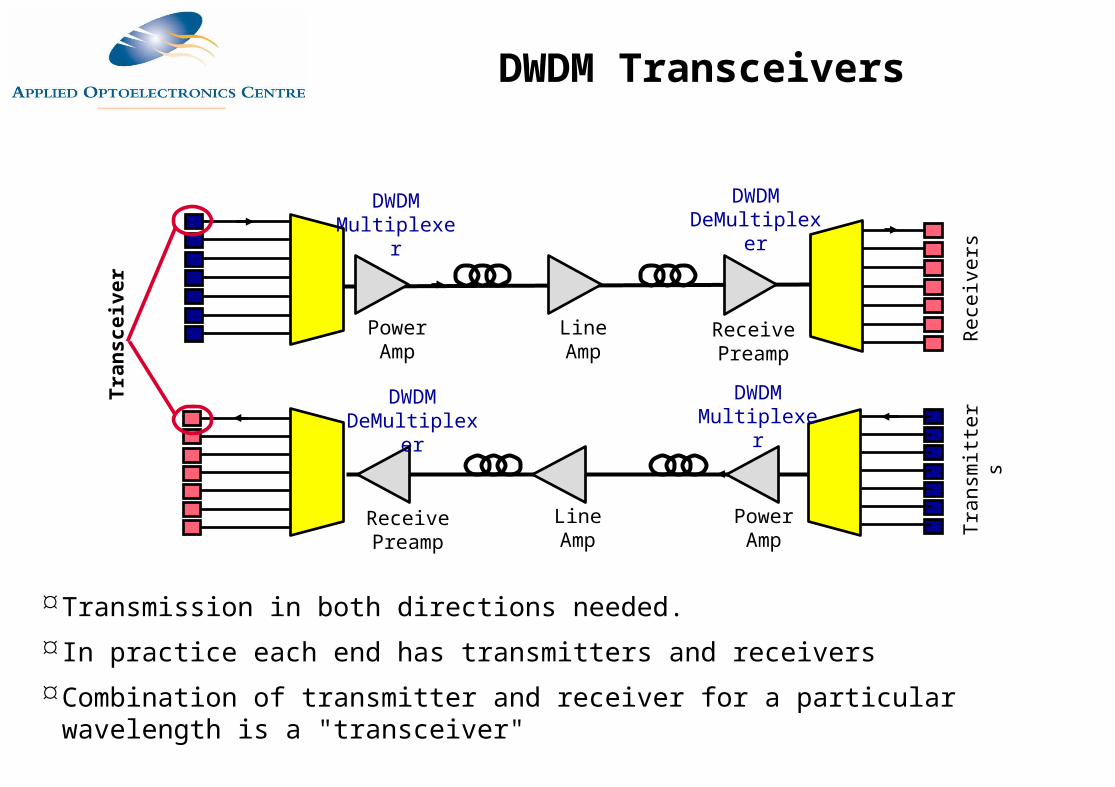
Transmission in both directions needed. In practice each end has transmitters and receiversCombination of transmitter and receiver for a particular wavelength is a "transceiver"
DWDM Multiplexer
Power Amp
Line Amp
Receive Preamp
DWDM DeMultiplexer
Rec
eive
rsTr
ansm
itter
s
DWDM Multiplexer
Power Amp
Line Amp
Receive Preamp
DWDM DeMultiplexer
Tran
scei
ver
DWDM Transceivers
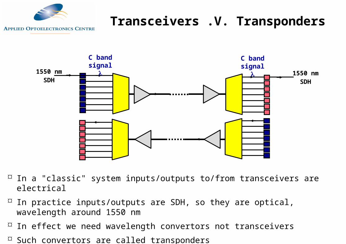
In a "classic" system inputs/outputs to/from transceivers are electrical In practice inputs/outputs are SDH, so they are optical, wavelength around 1550 nm In effect we need wavelength convertors not transceivers Such convertors are called transponders
1550 nmSDH
1550 nmSDH
C band signal
C band signal
Transceivers .V. Transponders
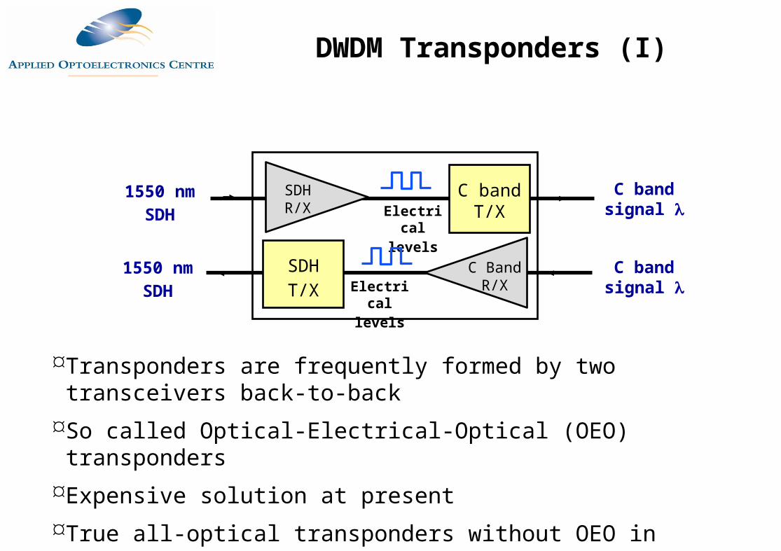
1550 nmSDH
C band signal
C band T/X
SDH R/X Electrical
levels
1550 nmSDH
C band signal
SDHT/X
C Band R/XElectrical
levels
Transponders are frequently formed by two transceivers back-to-backSo called Optical-Electrical-Optical (OEO) transponders Expensive solution at presentTrue all-optical transponders without OEO in development
DWDM Transponders (I)
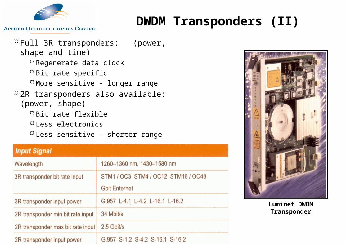
Full 3R transponders: (power, shape and time)
Regenerate data clock Bit rate specific More sensitive - longer range
2R transponders also available: (power, shape)
Bit rate flexible Less electronics Less sensitive - shorter range
Luminet DWDM Transponder
DWDM Transponders (II)
Bidirectional Transmission using
WDM
Source: Master 7_4
Source: Master 7_4
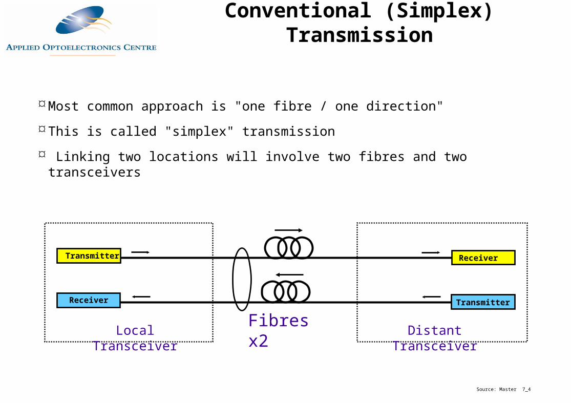
Local Transceiver Distant TransceiverFibres x2
Transmitter Receiver
Receiver Transmitter
Most common approach is "one fibre / one direction"
This is called "simplex" transmission
Linking two locations will involve two fibres and two transceivers
Conventional (Simplex) Transmission
A
B
WDMMux/Demux
AA
B
Receiver
Transmitter
Local Transceiver
WDMMux/Demux
B
A
B
Receiver
Transmitter
Distant TransceiverFibre
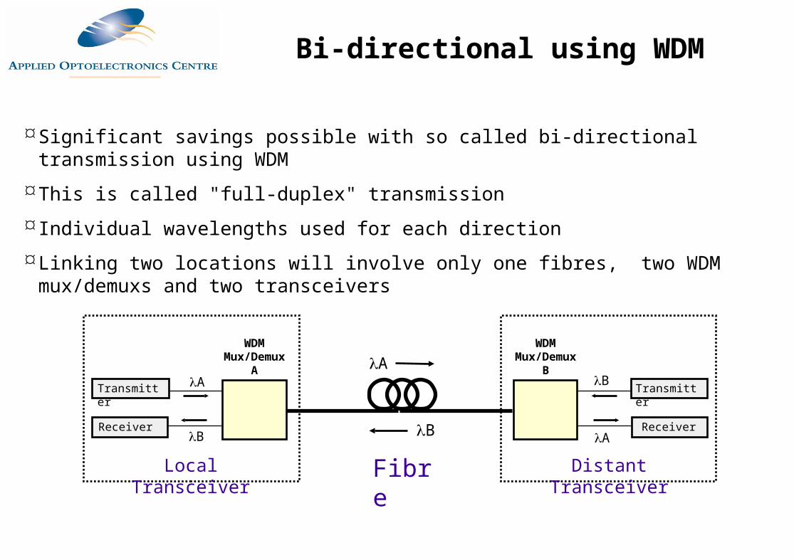
Significant savings possible with so called bi-directional transmission using WDM
This is called "full-duplex" transmission
Individual wavelengths used for each direction
Linking two locations will involve only one fibres, two WDM mux/demuxs and two transceivers
Bi-directional using WDM
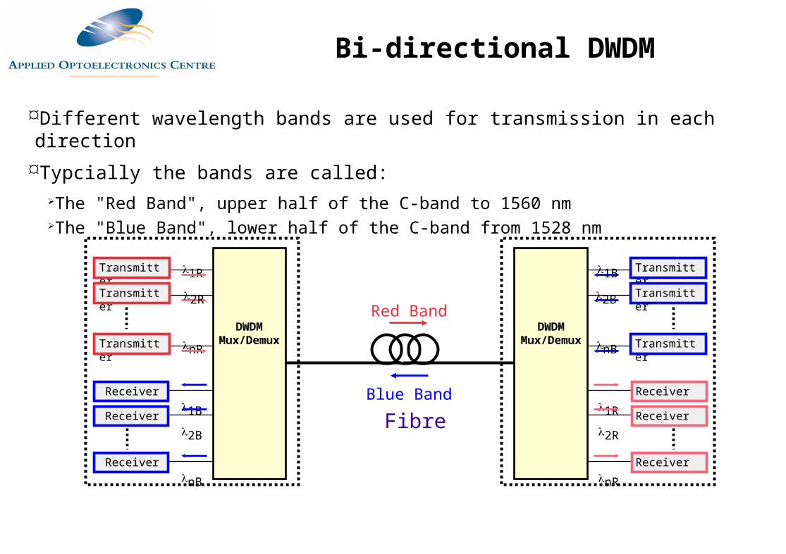
Different wavelength bands are used for transmission in each directionTypcially the bands are called:
The "Red Band", upper half of the C-band to 1560 nmThe "Blue Band", lower half of the C-band from 1528 nm
Red Band
FibreBlue BandReceiver
1BReceiver2B
ReceivernB
1RTransmitter
Transmitter
nRTransmitterDWDM
Mux/Demux
2R
Receiver1R Receiver2R
ReceivernR
1B Transmitter
Transmitter
nB TransmitterDWDM
Mux/Demux
2B
Bi-directional DWDM
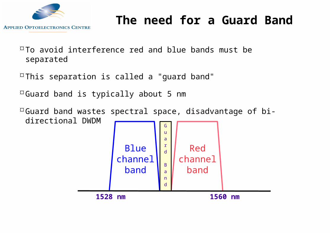
To avoid interference red and blue bands must be separated
This separation is called a "guard band"
Guard band is typically about 5 nm
Guard band wastes spectral space, disadvantage of bi-directional DWDM
Blue channel
band
Red channel
band
1528 nm 1560 nm
Guard
Band
The need for a Guard Band
TRANSMITTERA
Fibre, connectors and splices
RECEIVERB
TRANSMITTERB
RECEIVERA
Fibre Coupler Fibre Coupler
Frequency Fa
Frequency Fb
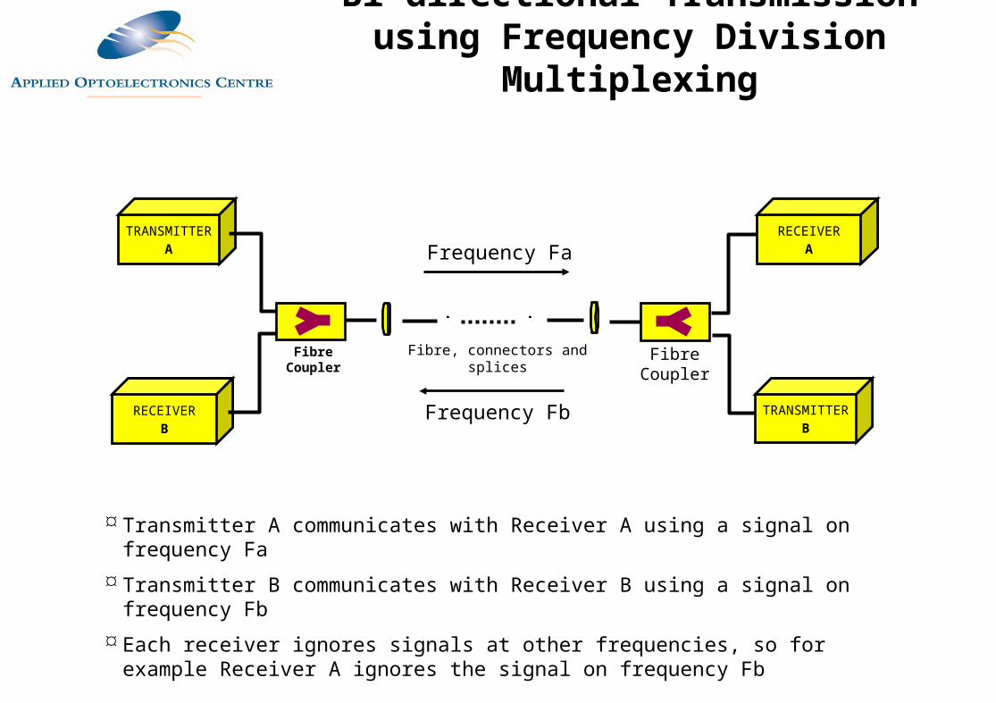
Transmitter A communicates with Receiver A using a signal on frequency Fa Transmitter B communicates with Receiver B using a signal on frequency Fb Each receiver ignores signals at other frequencies, so for example Receiver A ignores
the signal on frequency Fb
Bi-directional Transmission using Frequency Division Multiplexing
TRANSMITTERA
Fibre, connectors and splices
RECEIVERB
TRANSMITTERB
RECEIVERA
WDM Mux/Demux
WDM Mux/Demux
1330 nm
1550 nm
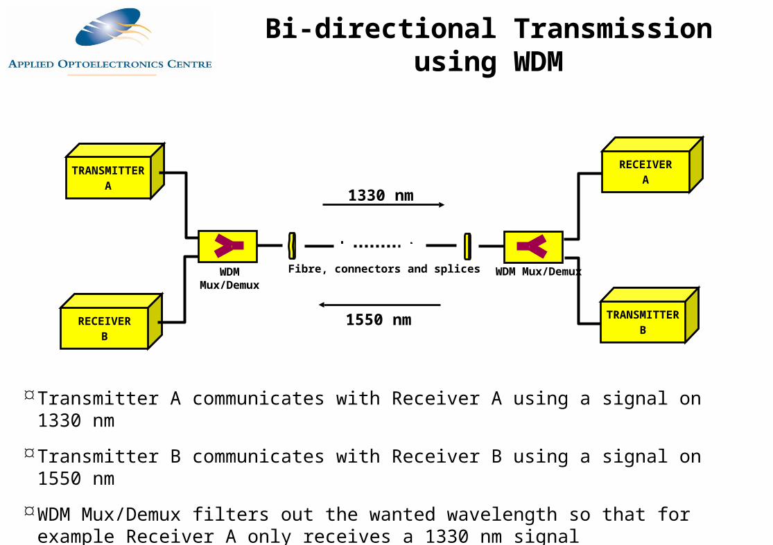
Transmitter A communicates with Receiver A using a signal on 1330 nm
Transmitter B communicates with Receiver B using a signal on 1550 nm
WDM Mux/Demux filters out the wanted wavelength so that for example Receiver A only receives a 1330 nm signal
Bi-directional Transmission using WDM
DWDM Issues
Spectral Uniformity and Gain Tilt
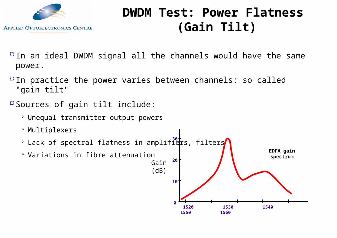
In an ideal DWDM signal all the channels would have the same power.
In practice the power varies between channels: so called "gain tilt"
Sources of gain tilt include: Unequal transmitter output powers Multiplexers Lack of spectral flatness in amplifiers, filters Variations in fibre attenuation
1520 1530 1540 1550 1560
30
20
10
0
Gain (dB)
EDFA gain spectrum
DWDM Test: Power Flatness (Gain Tilt)
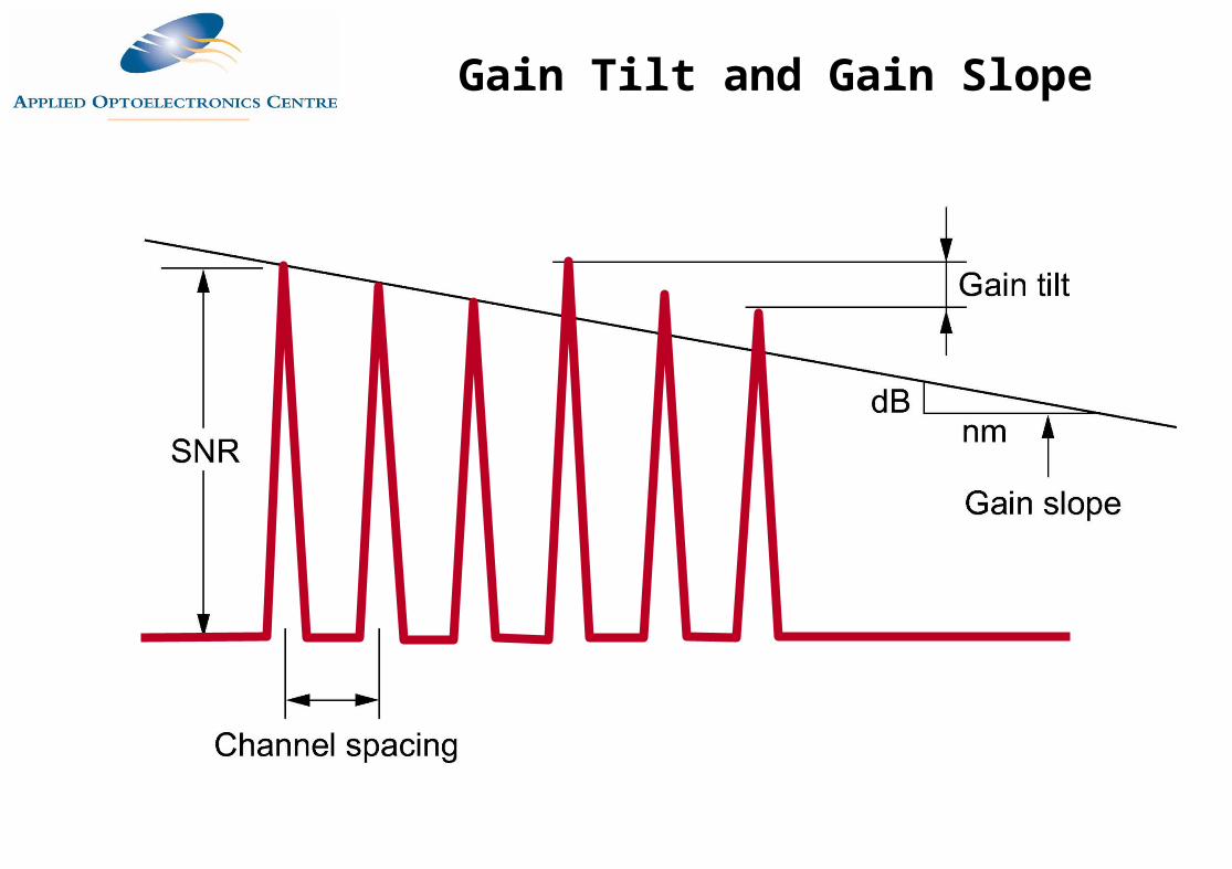
Gain Tilt and Gain Slope
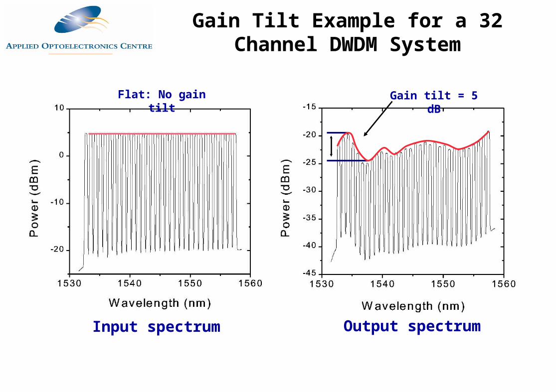
Output spectrum
Gain tilt = 5 dB
Input spectrum
Flat: No gain tilt
Gain Tilt Example for a 32 Channel DWDM System
DWDM Issues
Crosstalk between Channels
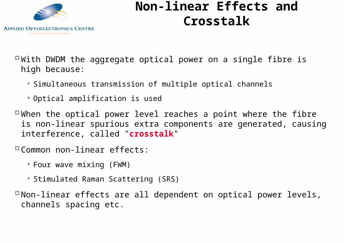
With DWDM the aggregate optical power on a single fibre is high because: Simultaneous transmission of multiple optical channels
Optical amplification is used
When the optical power level reaches a point where the fibre is non-linear spurious extra components are generated, causing interference, called "crosstalk"
Common non-linear effects: Four wave mixing (FWM)
Stimulated Raman Scattering (SRS)
Non-linear effects are all dependent on optical power levels, channels spacing etc.
Non-linear Effects and Crosstalk
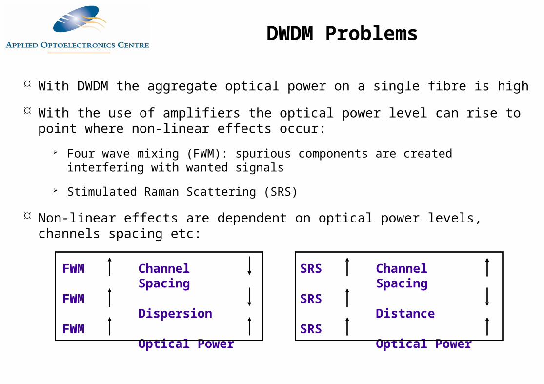
With DWDM the aggregate optical power on a single fibre is high
With the use of amplifiers the optical power level can rise to point where non-linear effects occur:
Four wave mixing (FWM): spurious components are created interfering with wanted signals
Stimulated Raman Scattering (SRS)
Non-linear effects are dependent on optical power levels, channels spacing etc:
FWM
FWM
FWM
Channel Spacing
Dispersion
Optical Power
SRS
SRS
SRS
Channel Spacing
Distance
Optical Power
DWDM Problems
Four Wave Mixing (FWM)
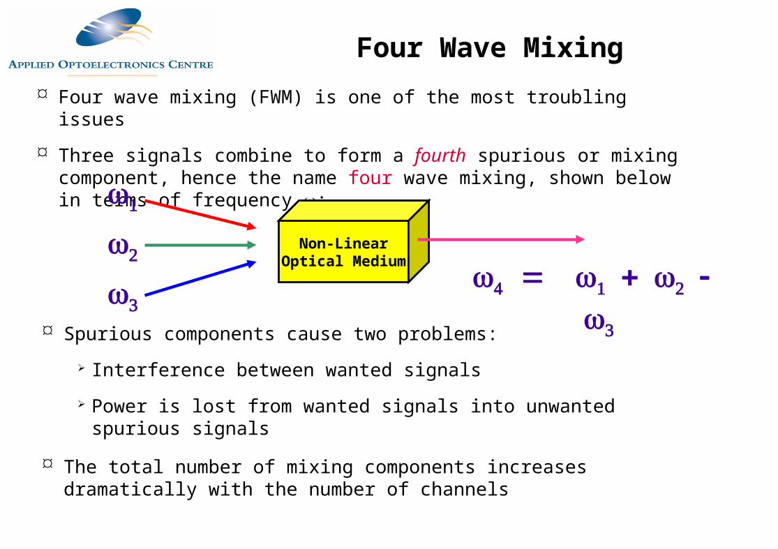
Four wave mixing (FWM) is one of the most troubling issues
Three signals combine to form a fourth spurious or mixing component, hence the name four wave mixing, shown below in terms of frequency :
Spurious components cause two problems:
Interference between wanted signals
Power is lost from wanted signals into unwanted spurious signals
The total number of mixing components increases dramatically with the number of channels
Four Wave Mixing
Non-Linear Optical Medium
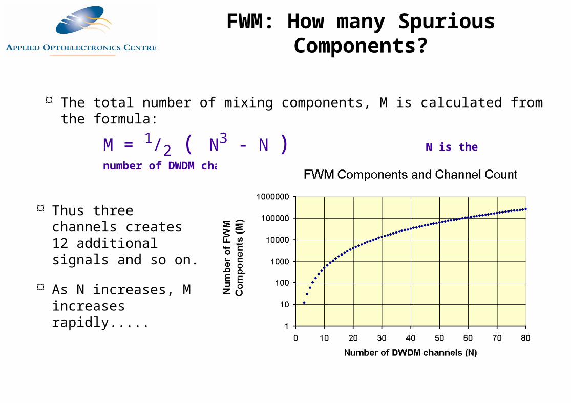
The total number of mixing components, M is calculated from the formula:
M = 1/2 ( N3 - N ) N is the number of DWDM channels
Thus three channels creates 12 additional signals and so on.
As N increases, M increases rapidly.....
FWM: How many Spurious Components?
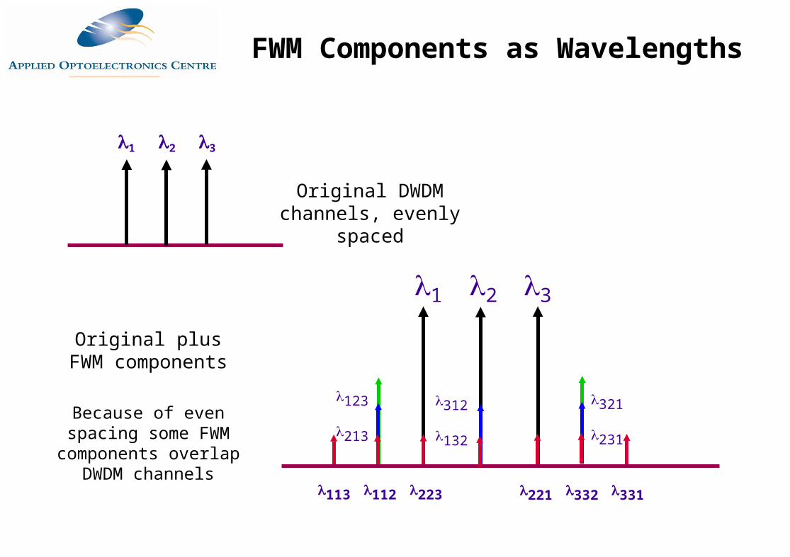
1 2 3
1 2 3
123
213
113 112 223 221 332 331
312
132
321
231
Original plus FWM components
Because of even spacing some FWM components overlap
DWDM channels
Original DWDM channels, evenly spaced
FWM Components as Wavelengths
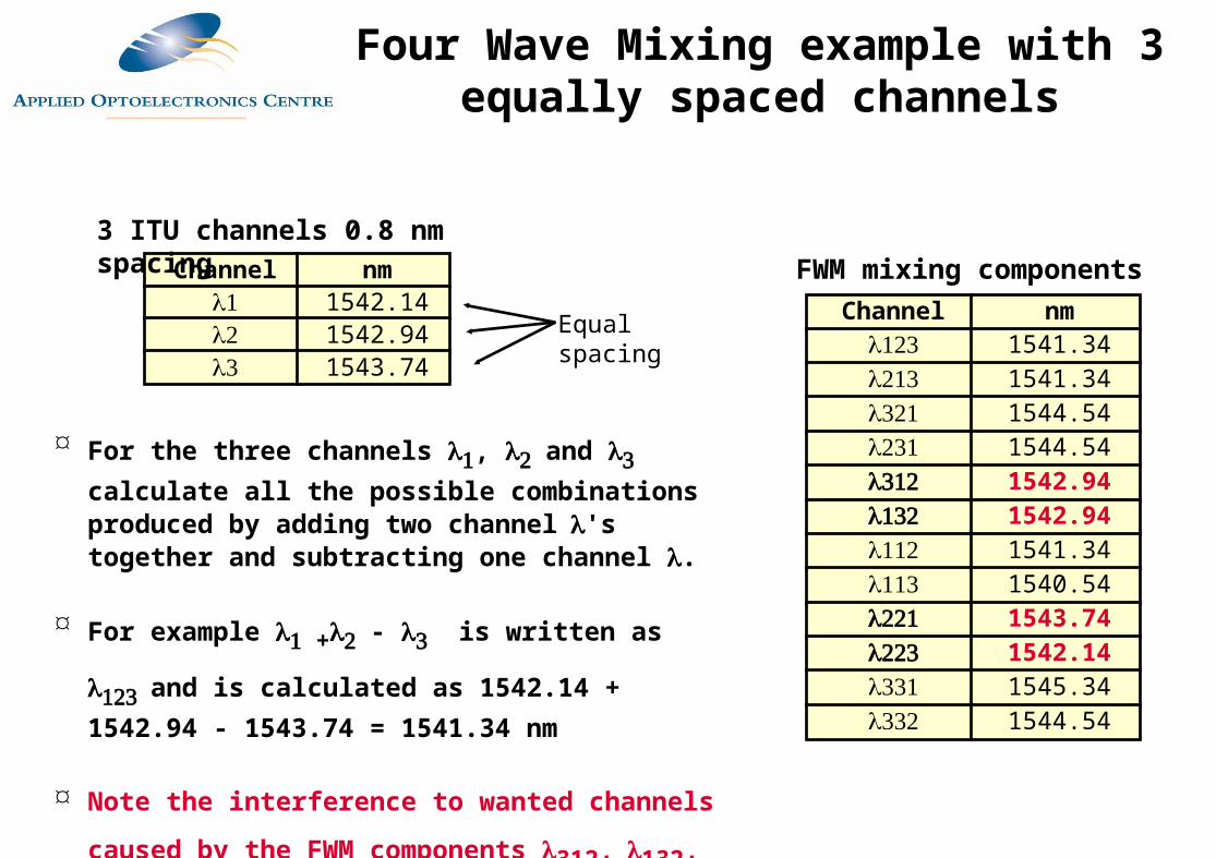
Channel nm 1542.14 1542.94 1543.74
3 ITU channels 0.8 nm spacing
For the three channels , and calculate all the possible combinations produced by adding two channel's together and subtracting one channel .
For example + - is written as and is calculated as 1542.14 + 1542.94 - 1543.74 = 1541.34 nm
Note the interference to wanted channels caused by
the FWM components 312,132, 221 and223
FWM mixing components Channel nm
1541.34 1541.34 1544.54 1544.54 1542.94 1542.94 1541.34 1540.54 1543.74 1542.14 1545.34 1544.54
Equal spacing
Four Wave Mixing example with 3 equally spaced channels
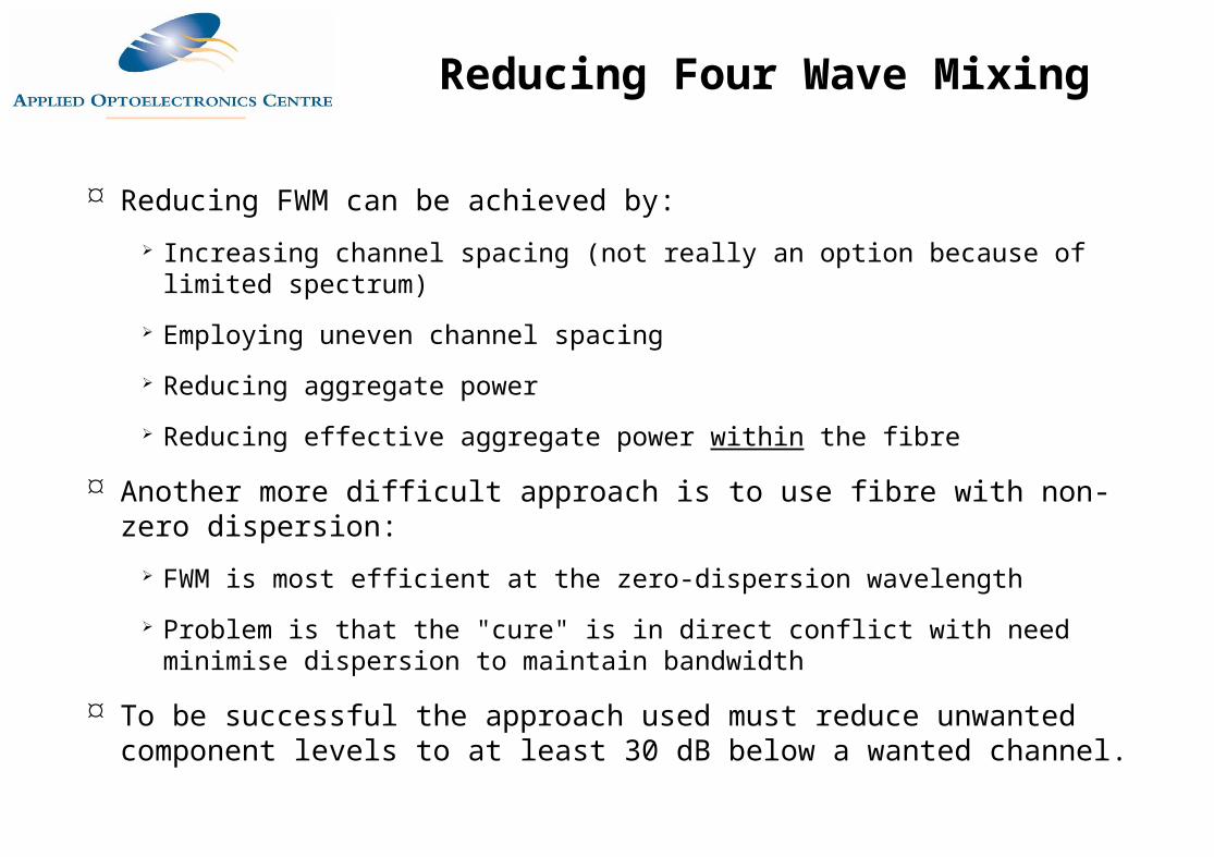
Reducing FWM can be achieved by: Increasing channel spacing (not really an option because of limited spectrum)
Employing uneven channel spacing
Reducing aggregate power
Reducing effective aggregate power within the fibre
Another more difficult approach is to use fibre with non-zero dispersion: FWM is most efficient at the zero-dispersion wavelength
Problem is that the "cure" is in direct conflict with need minimise dispersion to maintain bandwidth
To be successful the approach used must reduce unwanted component levels to at least 30 dB below a wanted channel.
Reducing Four Wave Mixing

Channel nm 1542.14 1542.94 1543.84
3 DWDM channels
As before for the three channels , and calculate all the possible combinations produced by adding two channel's together and subtracting one channel .
Note that because of the unequal spacing there is now no interference to wanted channels caused by the generated FWM components
FWM mixing components Channel nm
1541.24 1541.24 1544.64 1544.64 1543.04 1543.04 1541.34 1540.44 1543.74 1542.04 1545.54 1544.74
unequal spacing
Four Wave Mixing example with 3 unequally spaced channels
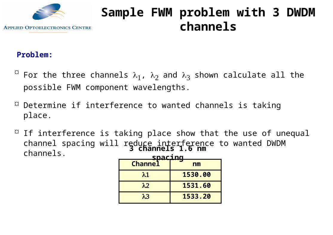
Channel nm 1530.00 1531.60 1533.20
3 channels 1.6 nm spacing
For the three channels , and shown calculate all the possible FWM component wavelengths.
Determine if interference to wanted channels is taking place.
If interference is taking place show that the use of unequal channel spacing will reduce interference to wanted DWDM channels.
Problem:
Sample FWM problem with 3 DWDM channels
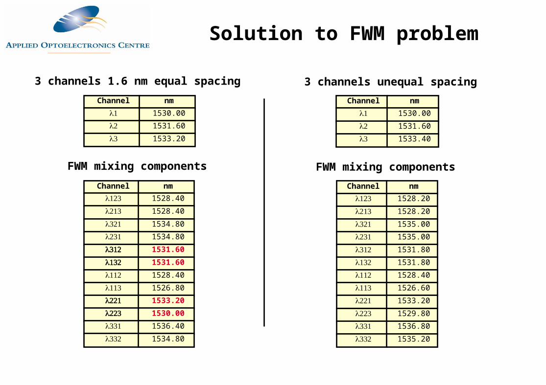
3 channels 1.6 nm equal spacing
FWM mixing components
Channel nm 1530.00
1531.60
1533.20
Channel nm 1528.40
1528.40
1534.80
1534.80
1531.60 1531.60 1528.40
1526.80
1533.20 1530.00 1536.40
1534.80
3 channels unequal spacing
FWM mixing components
Channel nm 1530.00
1531.60
1533.40
Channel nm 1528.20
1528.20
1535.00
1535.00
1531.80
1531.80
1528.40
1526.60
1533.20
1529.80
1536.80
1535.20
Solution to FWM problem
Traditional non-multiplexed systems have used dispersion shifted fibre at 1550 to reduce chromatic dispersion
Unfortunately operating at the dispersion minimum increases the level of FWM
Conventional fibre (dispersion minimum at 1330 nm) suffers less from FWM but chromatic dispersion rises
Solution is to use "Non-Zero Dispersion Shifted Fibre" (NZ DSF), a compromise between DSF and conventional fibre (NDSF, Non-DSF)
ITU-T standard is G.655 for non-zero dispersion shifted singlemode fibres
Reducing FWM using NZ-DSF
Provides small amount of dispersion over EDFA band
Non-Zero dispersion band is 1530-1565 (ITU C-Band)
Minimum dispersion is 1.3 ps/nm-km, maximum is 5.8 ps/nm-km
Very low OH attenuation at 1383 nm (< 1dB/km)
Dispersion Characteristics
Lucent TrueWave NZDSF
One way to improve on NZ-DSF is to increase the effective area of the fibre
In a singlemode fibre the optical power density peaks at the centre of the fibre core
FWM and other effect most likely to take place at locations of high power density
Large effective Area Fibres spread the power density more evenly across the fibre core
Result is a reduction in peak power and thus FWM
Reducing FWM using a Large Effective Area Fibre NZ-DSF
Corning LEAF has an effective area 32% larger than conventional NZ-DSF
Claimed result is lower FWM
Impact on system design is that it allows higher fibre input powers so span increases
Section of DWDM spectrum
NZ-DSF shows higher FWM components
LEAF has lower FWM and higher per
channe\l power
DWDM channel
FWM component
Corning LEAF
Wavelength Selection
Conventional DSF (G.653) is most affected by FWM
Using equal channel spacing aggravates the problem
ITU-T G.692 suggests a methodology for choosing unequal channel spacings for G.653 fibre
ITU suggest the use equal spacing for G.652 and G.655 fibre, but according to a given channel plan
Note that the ITU standards look at DWDM in frequency not wavelength
ITU Channel Allocation Methodology (I)
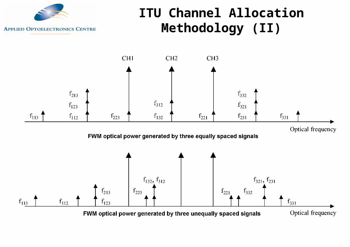
ITU Channel Allocation Methodology (II)
Basic rule is that each frequency (wavelength) is chosen so that no new powers generated by FWM fall on any channel
Thus channel spacing of any two channels must be different from any other pair
Complex arrangement based on the concept of a frequency slot "fs"
fs is the minimum acceptable distance between an FWM component and a DWDM channel
As fs gets smaller error rate degrades
For 10 Gbits/s the "fs" is 20 GHz.
ITU Channel Allocation Methodology (III)
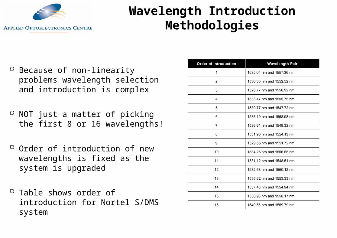
Wavelength Introduction Methodologies
Because of non-linearity problems wavelength selection and introduction is complex
NOT just a matter of picking the first 8 or 16 wavelengths!
Order of introduction of new wavelengths is fixed as the system is upgraded
Table shows order of introduction for Nortel S/DMS system
High Density DWDM
Date Manufacturer Channel Count Total Capacity
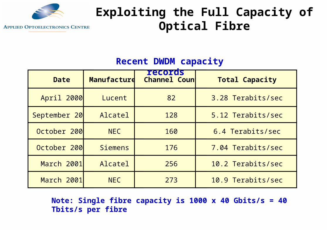
April 2000 Lucent 82 3.28 Terabits/sec
September 2000 Alcatel 128 5.12 Terabits/sec
October 2000 NEC 160 6.4 Terabits/sec
October 2000 Siemens 176 7.04 Terabits/sec
March 2001 Alcatel 256 10.2 Terabits/sec
March 2001 NEC 273 10.9 Terabits/sec
Note: Single fibre capacity is 1000 x 40 Gbits/s = 40 Tbits/s per fibre
Recent DWDM capacity records
Exploiting the Full Capacity of Optical Fibre
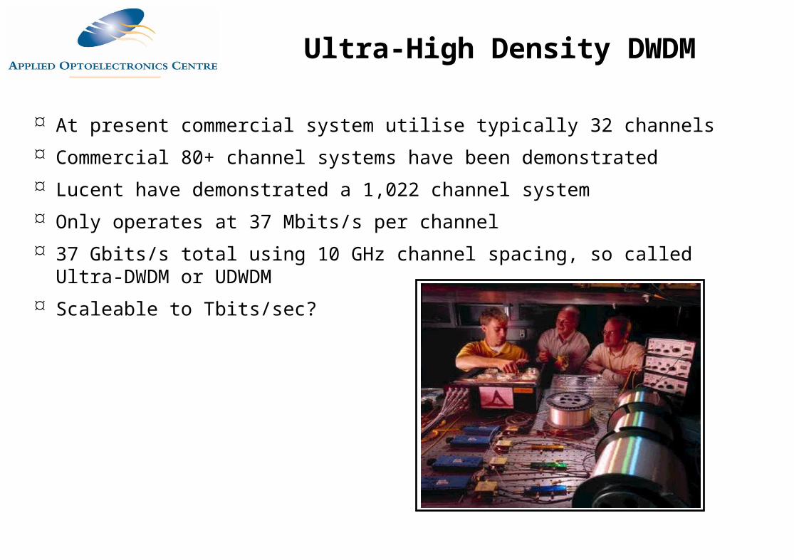
At present commercial system utilise typically 32 channels Commercial 80+ channel systems have been demonstrated Lucent have demonstrated a 1,022 channel system Only operates at 37 Mbits/s per channel 37 Gbits/s total using 10 GHz channel spacing, so called Ultra-DWDM or UDWDM Scaleable to Tbits/sec?
Ultra-High Density DWDM
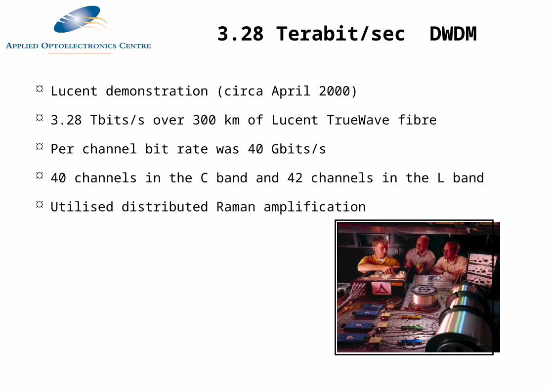
Lucent demonstration (circa April 2000)
3.28 Tbits/s over 300 km of Lucent TrueWave fibre
Per channel bit rate was 40 Gbits/s
40 channels in the C band and 42 channels in the L band
Utilised distributed Raman amplification
3.28 Terabit/sec DWDM
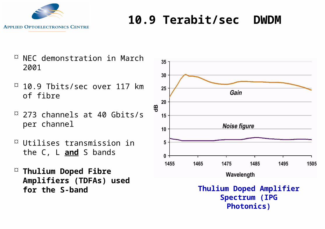
NEC demonstration in March 2001
10.9 Tbits/sec over 117 km of fibre
273 channels at 40 Gbits/s per channel
Utilises transmission in the C, L and S bands
Thulium Doped Fibre Amplifiers (TDFAs) used for the S-band
Thulium Doped Amplifier Spectrum (IPG Photonics)
10.9 Terabit/sec DWDM
Wavelength Division Multiplexing in LANs
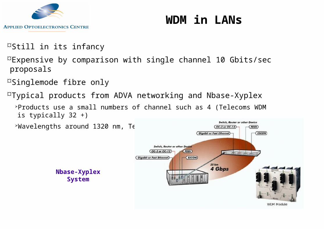
Still in its infancyExpensive by comparison with single channel 10 Gbits/sec proposalsSinglemode fibre onlyTypical products from ADVA networking and Nbase-Xyplex
Products use a small numbers of channel such as 4 (Telecoms WDM is typically 32 +)Wavelengths around 1320 nm, Telecoms systems use 1530-1570 nm
Nbase-Xyplex System
WDM in LANs
Coarse Wavelength Division Multiplexing
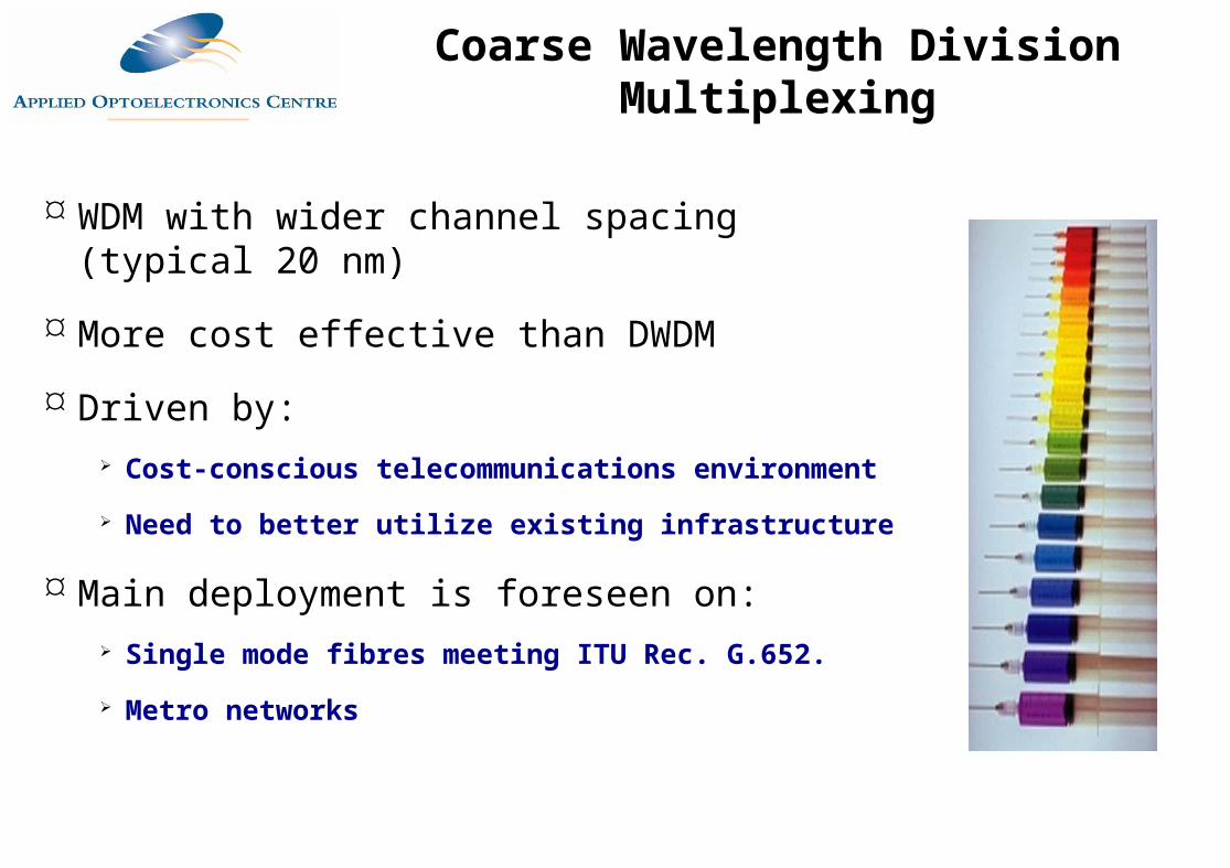
WDM with wider channel spacing (typical 20 nm)
More cost effective than DWDM
Driven by: Cost-conscious telecommunications environment Need to better utilize existing infrastructure
Main deployment is foreseen on: Single mode fibres meeting ITU Rec. G.652. Metro networks
Coarse Wavelength Division Multiplexing
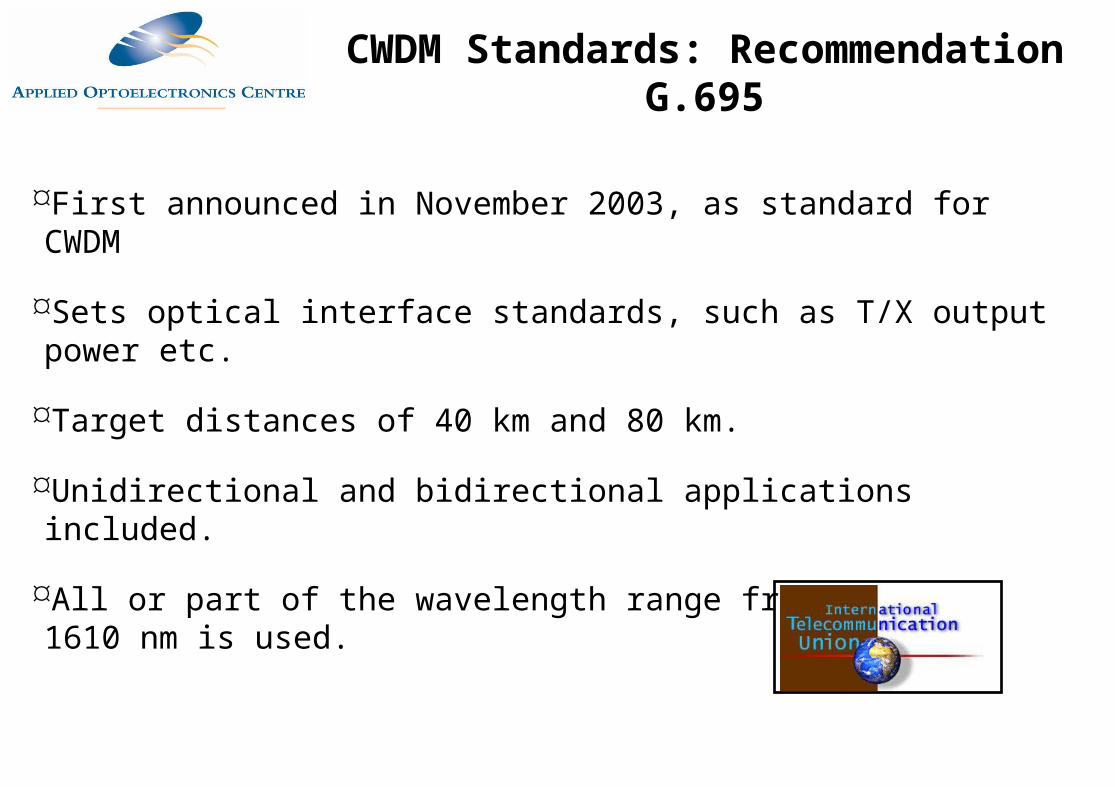
First announced in November 2003, as standard for CWDM
Sets optical interface standards, such as T/X output power etc.
Target distances of 40 km and 80 km.
Unidirectional and bidirectional applications included.
All or part of the wavelength range from 1270 nm to 1610 nm is used.
CWDM Standards: Recommendation G.695
1270 1290 1310 1330 1350 1370
1390 1410 1430 1450 1470 1490
1510 1530 1550 1570 1590 1610
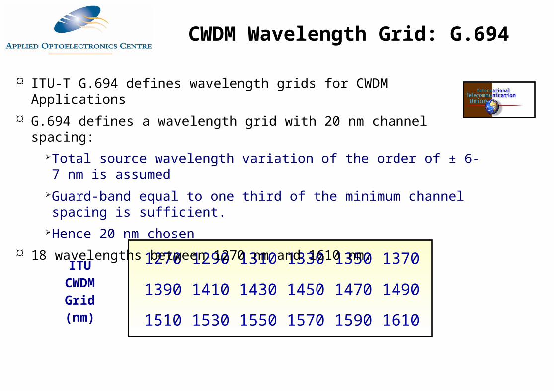
ITU-T G.694 defines wavelength grids for CWDM Applications G.694 defines a wavelength grid with 20 nm channel spacing:
Total source wavelength variation of the order of ± 6-7 nm is assumed Guard-band equal to one third of the minimum channel spacing is sufficient.
Hence 20 nm chosen 18 wavelengths between 1270 nm and 1610 nm.
ITUCWDM
Grid(nm)
CWDM Wavelength Grid: G.694
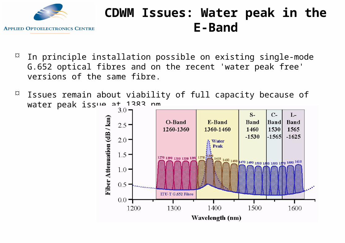
In principle installation possible on existing single-mode G.652 optical fibres and on the recent 'water peak free' versions of the same fibre.
Issues remain about viability of full capacity because of water peak issue at 1383 nm
CDWM Issues: Water peak in the E-Band
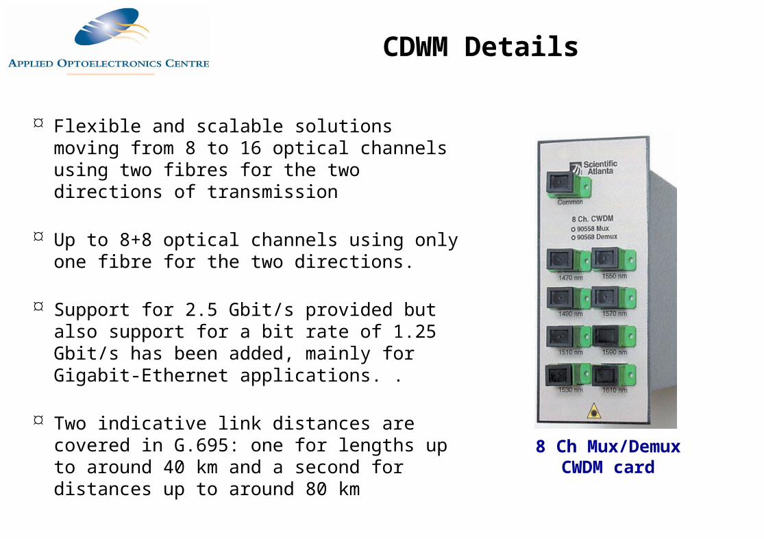
Flexible and scalable solutions moving from 8 to 16 optical channels using two fibres for the two directions of transmission
Up to 8+8 optical channels using only one fibre for the two directions.
Support for 2.5 Gbit/s provided but also support for a bit rate of 1.25 Gbit/s has been added, mainly for Gigabit-Ethernet applications. .
Two indicative link distances are covered in G.695: one for lengths up to around 40 km and a second for distances up to around 80 km
8 Ch Mux/Demux CWDM card
CDWM Details
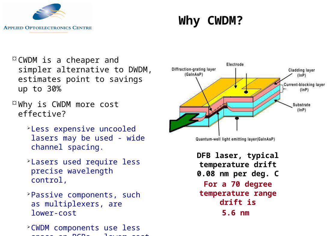
CWDM is a cheaper and simpler alternative to DWDM, estimates point to savings up to 30%
Why is CWDM more cost effective?
Less expensive uncooled lasers may be used - wide channel spacing.
Lasers used require less precise wavelength control,
Passive components, such as multiplexers, are lower-cost
CWDM components use less space on PCBs - lower cost
DFB laser, typical temperature drift 0.08 nm
per deg. CFor a 70 degree
temperature range drift is5.6 nm
Why CWDM?
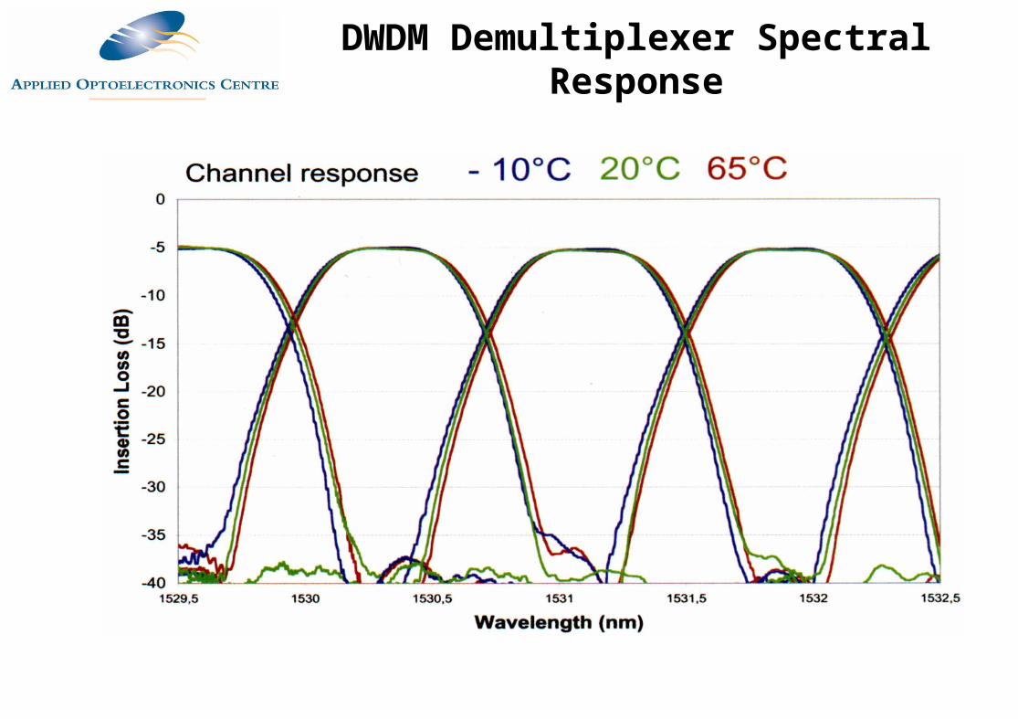
DWDM Demultiplexer Spectral Response
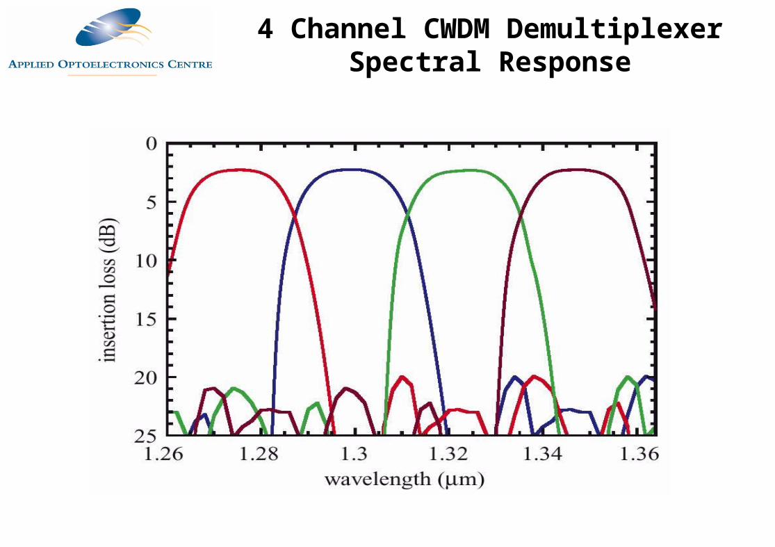
4 Channel CWDM Demultiplexer Spectral Response
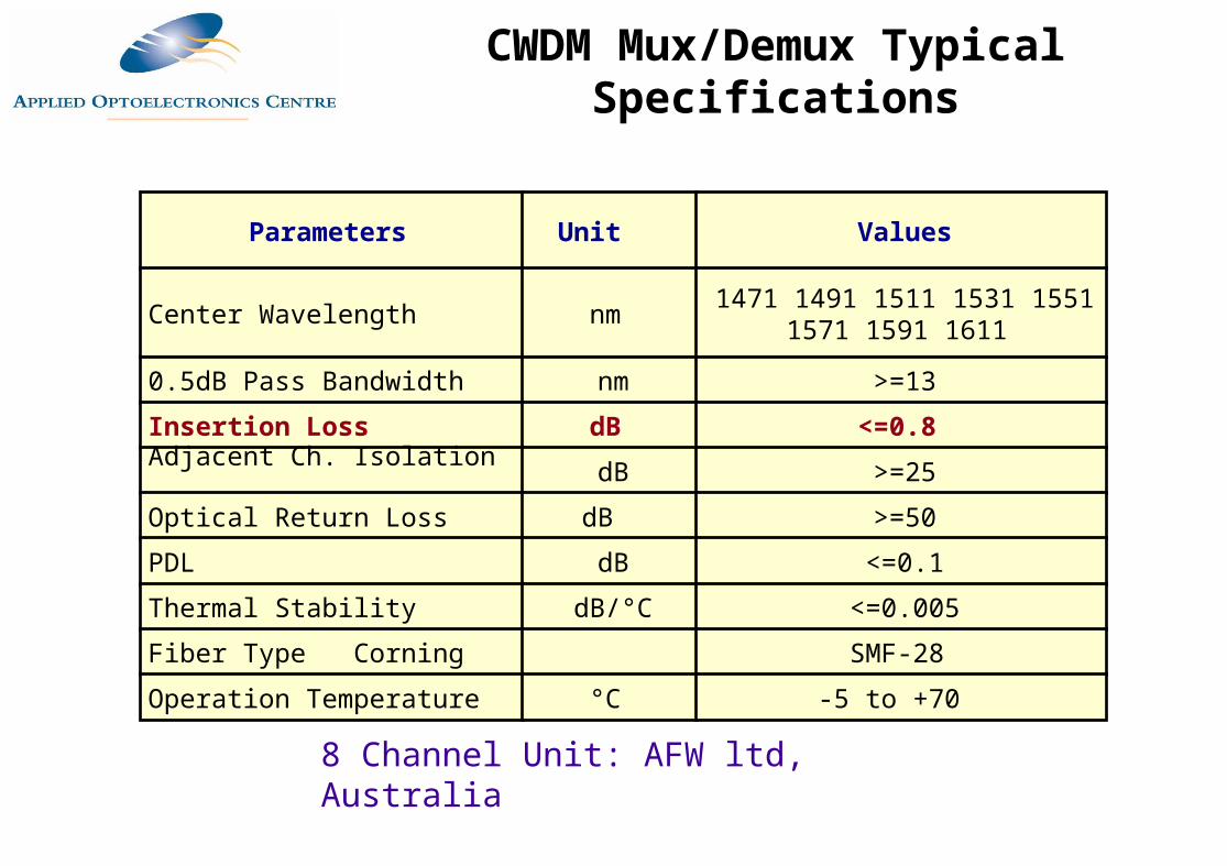
Parameters Unit Values
Center Wavelength nm 1471 1491 1511 1531 1551 1571 1591 1611
0.5dB Pass Bandwidth nm >=13
Insertion Loss dB <=0.8 Adjacent Ch. Isolation dB >=25
Optical Return Loss dB >=50
PDL dB <=0.1
Thermal Stability dB/°C <=0.005
Fiber Type Corning SMF-28
Operation Temperature °C -5 to +70
8 Channel Unit: AFW ltd, Australia
CWDM Mux/Demux Typical Specifications
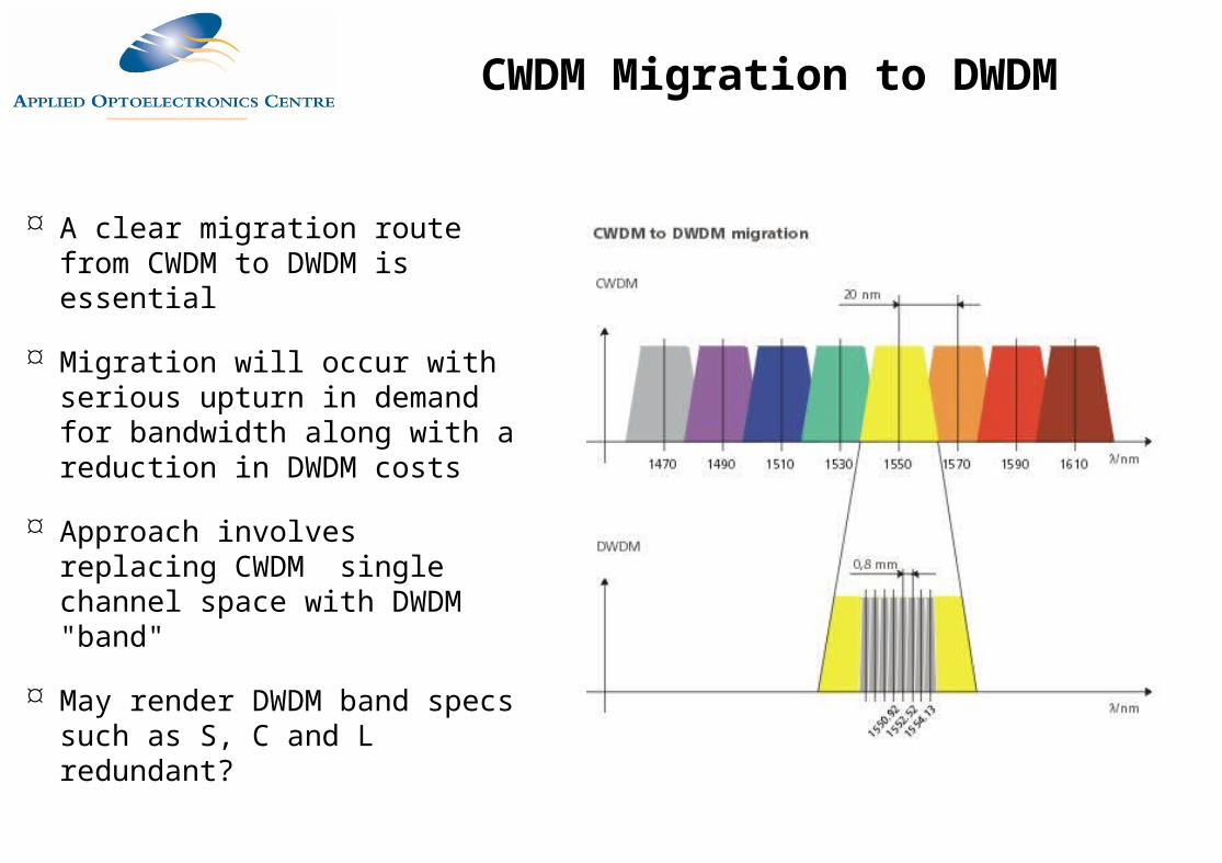
A clear migration route from CWDM to DWDM is essential
Migration will occur with serious upturn in demand for bandwidth along with a reduction in DWDM costs
Approach involves replacing CWDM single channel space with DWDM "band"
May render DWDM band specs such as S, C and L redundant?
CWDM Migration to DWDM