Wayside Energy Storage Assessment for Metra-Electric
67
Wayside Energy Storage Assessment for Metra-Electric A Study on How Implementing a Wayside Energy Storage System Would Impact Energy Usage on the Metra Electric District December 17, 2018
Transcript of Wayside Energy Storage Assessment for Metra-Electric

Wayside Energy StorageAssessment for Metra-Electric
A Study on How Implementing a Wayside Energy Storage System Would Impact Energy Usage on the Metra Electric District
December 17, 2018


392164 01 E C:\Users\gre75082\Desktop\SAMPLE.docx Mott MacDonald
Mott MacDonald 10 South LaSalle Street Suite 2520 Chicago IL 60603 United States of America
T (312) 894-5369
mottmac.com
Wayside Energy StorageAssessment for Metra-Electric
A Study on How Implementing a Wayside Energy Storage System Would Impact Energy Usage on the Metra Electric District
December 17, 2018


Mott MacDonald | Confidential | Wayside Energy Storage Assessment for Metra-ElectricA study on how implementing a Wayside Energy Storage System would impact Energy Usage on the Metra Electric District
392164 | 01 | E | December 17, 2018
C:\Users\gre75082\Desktop\Metra_LFA & Site Visit Report (public copy).docx
Issue and revision record
Revision Date Originator Checker Approver Description
A 18 Oct 2018 K Patel D Hetherington
J Green
M Walbrun First Issue
B 30 Nov 2018 K Patel D Hetherington
J Green
M Walbrun Updated for RTA and Metra comments
C 06 Dec 2018 K Patel D Hetherington
J Green
M Walbrun Final update for RTA and Metra comments
D 13 Dec 2018 K Patel D Hetherington
J Green
M Walbrun Final Report
E 13 Dec 2018 M Walbrun J Green D Hetherington Add non-financial benefits to WESS report data
Document reference: 392164 | 01 | E
Information class: Standard
This document is issued for the party which commissioned it and for specific purposes connected with the above-captioned project only. It should not be relied upon by any other party or used for any other purpose.
We accept no responsibility for the consequences of this document being relied upon by any other party, or being used for any other purpose, or containing any error or omission which is due to an error or omission in data supplied to us by other parties.
This document contains confidential information and proprietary intellectual property. It should not be shown to other parties without consent from us and from the party which commissioned it.
This report has been prepared solely for use by the party which commissioned it (the ‘Client’) in connection with the captioned project. It should not be used for any other purpose. No person other than the Client or any party who has expressly agreed terms of reliance with us (the ‘Recipient(s)’) may rely on the content, information or any views expressed in the report. We accept no duty of care, responsibility or liability to any other recipient of this document. This report is confidential and contains proprietary intellectual property.
Contents

Mott MacDonald | Confidential | Wayside Energy Storage Assessment for Metra-ElectricA study on how implementing a Wayside Energy Storage System would impact Energy Usage on the Metra Electric District
392164 | 01 | E | December 17, 2018
C:\Users\gre75082\Desktop\Metra_LFA & Site Visit Report (public copy).docx
Executive Summary 1
1 Introduction 2
2 Abbreviations 3
3 Project Background 4
3.1 Project Description 4 3.2 Scope 4
4 Simulation Input Data 5
4.1 Simulation Software Background 5 4.2 Scope of Simulation 5 4.3 Simulation Parameters 5 4.4 Paths and Timetables 7 4.5 WESS Inputs 7
5 Simulation Results 9
5.1 Existing Metra Operating Conditions 9 5.2 Simulations with added Wayside Energy Storage Systems 12 5.3 WESS at 51st Street TPSS 13 5.4 WESS at Front Avenue TPSS 14 5.5 WESS at Riverdale TPSS 15 5.6 WESS at Harvey TPSS 16 5.7 WESS at Vollmer TPSS 17 5.8 WESS at Matteson TPSS 18
5.8.1 2000 A rated WESS 18 5.8.2 1000 A rated WESS 18
5.9 Energy Savings Summary 19
6 Equipment Required 21
6.1 General 21 6.2 WESS 21
6.2.1 Super Capacitor 22 6.2.2 Flywheel 23 6.2.3 Frequency Regulation Market 23
7 TPSS Site Survey Results 24
7.1 Site Visit 24

Mott MacDonald | Confidential | Wayside Energy Storage Assessment for Metra-ElectricA study on how implementing a Wayside Energy Storage System would impact Energy Usage on the Metra Electric District
392164 | 01 | E | December 17, 2018
C:\Users\gre75082\Desktop\Metra_LFA & Site Visit Report (public copy).docx
7.2 General 24 7.3 National Electrical Code 24 7.4 Matteson TPSS 24 7.5 Riverdale TPSS 25 7.6 51st Street TPSS 26
8 Conclusions and Recommendations 28
A. Electrical Resistance 29
B. Plots 31
C. Manufacturer’s Information 56
D. Marked up TPSS Layout Drawings 57
E. Photos for Matteson TPSS 58
F. Photos for 51st Street TPSS 59
G. Photos for Riverdale TPSS 60

Mott MacDonald | Confidential | Wayside Energy Storage Assessment for Metra-Electric 1A study on how implementing a Wayside Energy Storage System would impact Energy Usage on the Metra Electric District
392164 | 01 | E | December 17, 2018
C:\Users\gre75082\Desktop\Metra_LFA & Site Visit Report (public copy).docx
Executive Summary
The RTA and Metra have undertaken an assessment of opportunities for deployment of wayside energy storage systems (WESS) on the Metra-Electric District commuter rail line in an effort to improve operational efficiency and capture potential new revenue streams. Wayside energy storage systems are able to capture lost energy from braking and have been used by several other US transit agencies. A Load Flow Analysis was undertaken for Metra on Mott MacDonald’s simulator program, TRAIN. The Load Flow Analysis provided information about the “station to station” runs where the most energy is being wasted in the train’s onboard resistors (rheostatic braking). To help identify which substations in these areas can be equipped with a WESS, Mott MacDonald built a peak hour model (06:30 to 08:30) and an off-peak hour model (10:00 to 12:00) to assess the difference in recovered regenerative energy during the peak and off-peak periods. The simulations were re-run with a WESS at Riverdale, Harvey, Vollmer, Matteson, 51st Street and Front Avenue TPSS to assess the amount of regenerative braking energy being reclaimed.
According to the current Metra operating schedule, the largest amount of energy wasted in rheostatic braking is on the Metra Electric District Main Line south of the Kensington station. Mott MacDonald then narrowed down to six TPSS sites which were suitable for the installation of the WESS. This report shows the approximate cost of energy savings of the modelled WESS at each site, and the approximate cost to install a WESS.
The Load Flow Analysis undertaken by Mott MacDonald identified that Matteson TPSS, 51st Street TPSS and Riverdale Tie Station (being upgraded to a TPSS in near future) would be the electrically preferred sites to install a WESS along the Metra Electric District Main Line. The site surveys of these three TPSS show that Matteson TPSS would be the preferred option from an installation perspective though it would require some civil work in terms of external grading as the WESS would be best located outside in a container.
The approximate total installation cost for a 1000 A, 8 kWh WESS is $850,000. With an approximate annual energy savings of 396.4 MWh, which at the $0.07 price per kWh Metra pays for electricity, equates to an annual energy savings of approximately $28,000. The economic payback period would be around 30 years.
The approximate total installation cost for a 2000 A, 8 kWh WESS is $1,100,000. With an approximate annual energy savings of 415.4 MWh, which at the $0.07 per kWh price Metra pays for electricity, equates to an annual energy savings of approximately $29,000. This would provide a payback period of around 38 years.
Based on this analysis, a WESS installation is not financially beneficial to Metra. However, there are other environmental and operational benefits that make it worthwhile, particularly if Metra is ever in a position to decrease the upfront capital cost through grants. Moreover, if Metra ever operates more service on the line, the potential benefits are also increased. Thus, it may be worthwhile to consider in the future.

Mott MacDonald | Confidential | Wayside Energy Storage Assessment for Metra-Electric 2A study on how implementing a Wayside Energy Storage System would impact Energy Usage on the Metra Electric District
392164 | 01 | E | December 17, 2018
C:\Users\gre75082\Desktop\Metra_LFA & Site Visit Report (public copy).docx
1 Introduction
The amount of the regenerated energy which is being wasted in the trains onboard resistors when the overhead contact system is not in a receptive state, can be utilized by using a WESS. Therefore, the ability of a WESS to store regenerated energy and release this back to the line when needed was the primary effort of the study.
Load Flow Analysis was undertaken for Metra on simulator program, TRAIN. Load Flow Analysis provides precise information about the station to station runs where the most energy is being wasted and the substations in these areas were equipped with a WESS and simulations were re-run to assess the amount of regenerative braking energy being reclaimed. Load Flow Analysis provides a reliable technical support to a proposed WESS position.
Mott MacDonald built a peak model (06:30 to 08:30) and an off-peak model (10:00 to 12:00) to assess the difference in recovered regenerative energy during the peak and off-peak periods. These results helped Mott MacDonald to be ascertain about the locations where the most energy is being wasted in the train’s onboard resistors.
The performance of the train was accurately simulated based upon the voltages, the train experience and the interaction between regenerated energy, substations, trains, and energy storage systems being correctly modelled. TRAIN was not only being used to position the WESS, but also to provide a charge/discharge cycle for the WESS that can be taken to, and discussed with, manufacturers in the next stage of design. TRAIN did breakdown the output data giving the insight as to how energy is being used and transferred. TRAIN provided output information graphically saving time in analysing the results.
Flywheel and Super-capacitors are recommended for WESS due to their quick charging and discharging characteristics. Two layouts are produced showing the size of the WESS when using super-capacitors and flywheel. This Final report gives the approximate cost of energy savings of the modelled WESS and the approximate cost to install a WESS.

Mott MacDonald | Confidential | Wayside Energy Storage Assessment for Metra-Electric 3A study on how implementing a Wayside Energy Storage System would impact Energy Usage on the Metra Electric District
392164 | 01 | E | December 17, 2018
C:\Users\gre75082\Desktop\Metra_LFA & Site Visit Report (public copy).docx
2 Abbreviations
Abbreviation Name
A Ampere
AC Alternating Current
DC Direct Current
FRM Frequency Regulation Market
kW Kilowatt
kWh Kilowatt-hour
LFA Load Flow Analysis
MM Mott MacDonald
NEC National Electrical Code
NICTD Northern Indiana Commuter Transportation District
OCS Overhead Contact System
RTA Regional Transportation Authority
RTU Remote Terminal Unit
SCADA Supervisory Control and Data Acquisition
SEPTA Southeastern Pennsylvania Transportation Authority
TPSS Traction Power Substation
V Volt
WESS Wayside Energy Storage System

Mott MacDonald | Confidential | Wayside Energy Storage Assessment for Metra-Electric 4A study on how implementing a Wayside Energy Storage System would impact Energy Usage on the Metra Electric District
392164 | 01 | E | December 17, 2018
C:\Users\gre75082\Desktop\Metra_LFA & Site Visit Report (public copy).docx
3 Project Background
3.1 Project Description
In an effort to improve operational efficiency, Metra and the Regional Transportation Authority (RTA) has requested Mott MacDonald investigate the effects of installing wayside energy storage systems (WESS) on the Metra Electric District rail system along the Main Line.
Regenerative braking is where a train uses the motors as generators in order to generate power and provide a braking force. However, in order for the generator to provide a braking force the power generated by the motors must be used. The power is consumed in three ways:
1) The train powers its own auxiliary load2) The train outputs power back onto the overhead contact system (OCS) which can be
consumed by other nearby trains3) The power is wasted in on board resistors (rheostatic braking).
The trains will use the regenerated power to provide power to their own auxiliary load first and then try to output excess energy to other trains. But where there are no other trains within the effective distance that want to use the power, then the excess power is diverted into the train’s own onboard resistors and wasted as heat energy.
In order to reduce this wasted energy, a WESS can be installed. The WESS will increase the receptivity of the traction power network, and a train that is braking will be able to generate energy and send it into the WESS when there are no other trains nearby to utilize this excess energy, rather than having to waste the energy in its own onboard resistors.
The most common types of WESS are (in no particular order) batteries, capacitors, and flywheels, although this report does not seek RTA and Metra to limit itself only to these technologies.
3.2 Scope
The WESS(s) modeled in the Load Flow Analysis are located in traction power substations (TPSS) that service Metra’s Electric District Main Line. However, the Metra Electric District Main Line is not the only alignment that needed to be modelled as it is interconnected with Metra Electric District branch lines and NICTD.
In order to identify the optimum locations for WESS installation, one first needs to understand where on the Metra Electric District system the trains are wasting the largest amount of energy in the onboard resistors. This information can only be determined by undertaking a Load Flow Analysis of the entire Metra Electric District system (and the interconnected NICTD system). It is important to model both the peak and off-peak hours flow of trains as the interaction between trains and the flow of regenerative braking will be different due to the different headways.
Mott MacDonald than analyze the results of these simulations to determine the annual energy savings and the potential return on investment for a WESS along the Metra Electric District Main Line.

Mott MacDonald | Confidential | Wayside Energy Storage Assessment for Metra-Electric 5A study on how implementing a Wayside Energy Storage System would impact Energy Usage on the Metra Electric District
392164 | 01 | E | December 17, 2018
C:\Users\gre75082\Desktop\Metra_LFA & Site Visit Report (public copy).docx
4 Simulation Input Data
4.1 Simulation Software Background
To analyze the Metra Electric District traction power electrification system, Mott MacDonald used its proprietary simulation software known as TRAIN. This simulation program models the behavior of traction power system parameters by determining details of system performance and thus suggesting the suitability of a particular potential location. The TRAIN simulator has been validated for accuracy on the London Underground system and has been used in many transit systems throughout North America and around the world. By inputting the physical and electrical characteristics of each line operating within a traction power system, along with the traction power substations, vehicles, and civil alignment, the simulator provides numerical and graphical outputs showing the resultant power and voltages that will be exhibited on each line. Within the program, the operational parameters for each particular transit system are considered, and the impacts are analyzed.
4.2 Scope of Simulation
The overall objective of this LFA was to determine potential locations for a TPSS to be installed along the Metra Electric District Main Line where a WESS can be added, that will effectively store the excess energy produced by trains’ regenerative braking and distribute it to other trains in need of power.
In order to accomplish this objective, two base case simulations were prepared, one for peak hours and one for off-peak hours timetables. The peak hours timetable base case modeled the normal morning weekday rush hour timetable from 06:30 to 08:30. The off-peak hours base case modeled the normal midday off-peak hours timetable from 10:00 to 12:00.
Once these base cases were established, further simulations were performed in order to study how installing a WESS along the Metra Electric District Main Line improved the efficiency in utilizing energy generated by regenerative braking. Mott MacDonald determined the best places to locate a WESS and performed separate simulations with a WESS in each location, to identify the system effects of a WESS installed at each of these locations. With these simulations, Mott MacDonald was able to calculate the size of the WESS both in terms of storage capacity and power rating.
The Load Flow Analysis identified Matteson TPSS, Riverdale TPSS, and 51st Street TPSS as the electrically preferred sites for the WESS. Note that presently Riverdale “TPSS” is a Tie Station, but as it will be upgraded to a TPSS in the near future, Metra requested Mott MacDonald model it as a full TPSS in the LFA.
4.3 Simulation Parameters
All inputs for the TRAIN model, including track profiles, vehicle data, and traction power substations and sectioning, were provided by Metra, and this section only provides a high-level overview of the inputs.
In order to perform the Load Flow Analysis, MM needed the following information to input into the TRAIN program for both the Metra Electric District Line and the relevant section of NICTD.

Mott MacDonald | Confidential | Wayside Energy Storage Assessment for Metra-Electric 6A study on how implementing a Wayside Energy Storage System would impact Energy Usage on the Metra Electric District
392164 | 01 | E | December 17, 2018
C:\Users\gre75082\Desktop\Metra_LFA & Site Visit Report (public copy).docx
Table 4-1 summarizes the extents each line has been modelled.
Table 4-1 Summary of Extents of Alignments Modeled
Alignment From To
Metra Electric District Line Chicago Millennium Station University Park Station
Blue Island Branch State Street Station Blue Island Station
South Chicago Branch Stony Island Station 93rd Street Station
NICTD Line Hegewisch Station East Chicago Station
Table 4-2 contains the electrical parameters used in the TRAIN simulation files.
Table 4-2 Electrical Parameters
Description Input
Nominal Voltage (V DC) 1500
Substation No Load Voltage (V DC) ((Assumed: 10% Regulation) 1650
Maximum Regen Voltage Metra (V DC) 1750
Maximum Regen Voltage NICTD (V DC) 1650
Millennium Station to 63rd Street Station OCS (micro-ohm/meter) 45.6
63rd Street Station to University Park Station OCS (micro-ohm/meter) 52.7
NICTD Line OCS (micro-ohm/meter) 24.26
115 lb. running rail (micro-ohm/meter)
(Consists of 2-115 lb. running rail)
15.7
1,500 kcmil cable (micro-ohm/meter) 28.14
All resistance values are based on rail and cable resistance values provided by Metra. See Appendix A for calculations of resistance values.
The 1,500 kcmil cable resistance applies to substation positive and negative feeders. The length and number of cables per feeder varies for each substation.
Position and ratings of TPSS were derived from Traction Power one-line diagram drawing set and DC protective relay setting study report provided by Metra.

Mott MacDonald | Confidential | Wayside Energy Storage Assessment for Metra-Electric 7A study on how implementing a Wayside Energy Storage System would impact Energy Usage on the Metra Electric District
392164 | 01 | E | December 17, 2018
C:\Users\gre75082\Desktop\Metra_LFA & Site Visit Report (public copy).docx
4.4 Paths and Timetables
Peak and Off-Peak hours timetables were derived utilizing the Metra Electric District 2018 employee train schedule and South Shore Line 2017 timetable no.1 for weekday trains. The morning peak hours simulation was based on the time period from 06:30 to 08:30. The off-peak base case modeled the normal midday off-peak timetable, covering the hours between 10:00 and12:00.
4.5 WESS Inputs
The WESS units modelled in each of the TRAIN simulations in this report, utilize a capacitor -type energy storage system. This should not be interpreted as a recommendation that the capacitor type WESS is the preferred type for deploying along the Metra Electric District Main Line. From an energy utilization standpoint, all WESS methods are viable. The type is noted here in order to assist the reader in interpreting the WESS Total Energy Stored graphical results produced by TRAIN for simulations at Matteson TPSS. Refer to Appendix B for graphs.
Table 4-3 WESS Inputs
Description Input
Maximum Energy stored in WESS (kWh) 10.31
Minimum Energy stored in WESS (kWh) 2.33
Max line charge / discharge current (kA) 2/2 * or 1/1 *
Efficiency (Charging) 0.98
Efficiency (Discharging) 0.98
* Initial WESS simulations were undertaken using a 2000 A line limit (as provided in this report),but an additional simulation (documented in section 5.8.2) was undertaken to check the effect of lowering the current limit to 1000 A. This made very little difference regarding the energy saved, so MM has evaluated the effectiveness of a WESS with a 1000 A limit. (as provided in Appendix B)
In the TRAIN program the WESS is modelled in one of three modes:
IDLE
The WESS is neither charging nor discharging
CHARGING
When the voltage at the TPSS busbar increases to a preset value the WESS goes into charge mode. In charge mode the WESS will draw up to the maximum allowed current in an attempt to bring the TPSS busbar voltage down to a preset voltage target. The WESS will carry on charging until either it is fully charged or the load builds up so that the charging current is reduced to zero in the attempt to maintain the busbar voltage target. The WESS will return to IDLE mode.

Mott MacDonald | Confidential | Wayside Energy Storage Assessment for Metra-Electric 8A study on how implementing a Wayside Energy Storage System would impact Energy Usage on the Metra Electric District
392164 | 01 | E | December 17, 2018
C:\Users\gre75082\Desktop\Metra_LFA & Site Visit Report (public copy).docx
DISCHARGING
When the voltage at the TPSS busbar decreases to a preset value the WESS goes into discharge mode. In discharge mode the WESS will output up to the maximum allowed current in an attempt to bring the TPSS busbar voltage up to a preset voltage target. The WESS will continue discharging until either it is empty, or the load reduces so that the discharging current is reduced to zero in the attempt to maintain the busbar voltage target. The WESS will then return to IDLE mode.
Table 4-4 shows the voltage targets used by the WESS for the simulations. These remain the same between sites as the minimum, maximum, and average busbar voltages are similar at each site.
Table 4-4 WESS Voltage Target
TPSS Start Charging Voltage
Charging Target Voltage
Start Discharging
Voltage
Target Discharging
Voltage
All 1680 1660 1600 1620
NOTE: These values can be adjusted during further simulations to optimize the WESS in subsequent design stages and also during testing and commissioning of the WESS on site. For reference, the “no load” voltage of the TPSS is 1650 V, the nominal voltage is 1500 V, and the maximum regenerative voltage is 1750 V for Metra Electric District Main Line and 1650 V for NICTD Line.

Mott MacDonald | Confidential | Wayside Energy Storage Assessment for Metra-Electric 9A study on how implementing a Wayside Energy Storage System would impact Energy Usage on the Metra Electric District
392164 | 01 | E | December 17, 2018
C:\Users\gre75082\Desktop\Metra_LFA & Site Visit Report (public copy).docx
5 Simulation Results
5.1 Existing Metra Operating Conditions
Table 5-1 and Table 5-2 show the average regenerative braking energy that is lost through rheostatic braking as trains travel from station to station. These losses occur because there are no other nearby trains within close enough proximity that they could accept power from the regenerative current the train generates as it brakes.
The results below show that the largest amount of energy wasted in rheostatic braking occurs on the Metra Electric District Main Line south of Kensington station.
Some energy is lost to rheostatic braking between Kensington and 63rd Street station, and between 51st Street to Museum Campus station, but it is difficult to ascertain geographically exactly where the regenerated energy is wasted. Therefore, these trains are not included in the table.
There are generally less losses north of Kensington Street station, as all the branch lines and NICTD are travelling together to Millennium station, and the higher number of trains means that the natural receptivity of those lines to regenerative braking will be higher.
Table 5-1 Base Case Station to Station NB Average Regenerative Braking Energy Losses
From Station To Station
Peak
Timetable
Average
Regen Energy
Losses (kWh)
Off-Peak
Timetable
Average Regen
Energy Losses
(kWh)
Percentage
Energy
Loss Peak
Hours
Percentage
Energy
Loss Off
Peak
Hours
University Park Richton Park 46.6 44.3 64.5 82.1 Richton Park Matteson 11.3 20.3 44.4 74.2 Matteson 211th Street 21.0 32.7 52.1 81.7 211th Street Olympia Fields 29.2 39.3 52.7 73.0 Olympia Fields Flossmoor 38.3 35.9 73.7 66.1 Flossmoor Homewood 34.4 12.9 61.4 26.7Homewood Calumet 18.6 22.4 52.8 65.0 Calumet Hazel Crest 25.9 30.3 60.5 73.1Hazel Crest Harvey 35.0 37.5 64.6 72.0 Harvey 147th Street 32.3 39.6 60.9 75.3 147th Street Ivanhoe 28.4 35.0 59.6 74.0 Ivanhoe Riverdale 28.0 38.7 51.8 73.7Riverdale Kensington 9.8 23.3 24.7 61.0
63rd Street 59th Street 13.2 13.4 24.1 36.7
59th Street 55th-56th-57th Street 12.9 13.2
20.5 32.2
55th-56th-57th Street 51st-53rd Street 10.9 12.8 15.7 32.5 Museum Campus Van Buren 0.0 0.0 0.0 0.0 Van Buren Millennium 0.0 0.0 0.0 0.0

Mott MacDonald | Confidential | Wayside Energy Storage Assessment for Metra-Electric 10A study on how implementing a Wayside Energy Storage System would impact Energy Usage on the Metra Electric District
392164 | 01 | E | December 17, 2018
C:\Users\gre75082\Desktop\Metra_LFA & Site Visit Report (public copy).docx
Table 5-2 Base Case Station to Station SB Average Regenerative Braking Energy Losses
From Station To Station
Peak Timetable
Average Regen
Energy Losses
(kWh)
Off-Peak
Timetable
Average Regen
Energy Losses
(kWh)
Percentage
Energy
Loss Peak
Hours
Percentage
Energy
Loss Off
Peak
Hours
Millennium Van Buren 0.0
0.00.0 0.0
Van Buren Museum Campus
0.0 0.0
0.0 3.1
51st-53rd Street 55th-56th-57th Street 13.3 15.4
16.1 32.6
55th-56th-57th Street
59th Street 9.8 14.8
15.5 31.5
59th Street 63rd Street 6.1 N/A 11.7 N/A 63rd Street 75th Street 18.7 N/A 21.7 N/A 75th Street 79th Street 18.9 N/A 39.7 N/A 79th Street 83rd Street 11.6 N/A 24.6 N/A 83rd Street 87th Street 19.3 N/A 41.5 N/A 87th Street 91st Street 12.5 N/A 28.1 N/A 91st Street 95th Street 1.9 N/A 14.5 N/A 95th Street 103rd Street 19.9 N/A 28.2 N/A 103rd Street 107th Street 11.8 N/A 23.5 N/A 107th Street 111th Street 7.4 N/A 21.0 N/A 111th Street Kensington 0.2 N/A 1.2 N/A Kensington Riverdale 22.7 34.4 45.3 70.8Riverdale Ivanhoe 20.7 38.9 36.0 71.9 Ivanhoe 147th Street 18.1 32.8 39.1 74.4147th Street Harvey 12.1 38.9 16.2 71.9 Harvey Hazel Crest 31.6 38.8 59.2 74.8Hazel Crest Calumet 19.2 22.1 55.2 64.0 Calumet Homewood 7.6 11.1 31.4 39.5Homewood Flossmoor 21.0 33.8 30.8 64.5 Flossmoor Olympia Fields 20.8 37.1 40.8 74.0Olympia Fields 211th Street 11.8 37.4 20.8 74.1 211th Street Matteson 17.7 26.0 47.7 79.4 Matteson Richton Park 8.1 11.1 34.9 63.0 Richton Park University Park 34.7 43.6 67.5 84.9
The “station to station” trips with the largest amount of energy wasted in rheostatic braking during the off-peak hour simulation are shown in Figure 1.

Mott MacDonald | Confidential | Wayside Energy Storage Assessment for Metra-Electric 11A study on how implementing a Wayside Energy Storage System would impact Energy Usage on the Metra Electric District
392164 | 01 | E | December 17, 2018
C:\Users\gre75082\Desktop\Metra_LFA & Site Visit Report (public copy).docx
Figure 1 – Highest Average Regenerated Energy Wasted in On Board resistors
0.0
5.0
10.0
15.0
20.0
25.0
30.0
35.0
40.0
45.0
50.0E
nerg
y (k
Wh)
Peak Off peak

Mott MacDonald | Confidential | Wayside Energy Storage Assessment for Metra-Electric 12A study on how implementing a Wayside Energy Storage System would impact Energy Usage on the Metra Electric District
392164 | 01 | E | December 17, 2018
C:\Users\gre75082\Desktop\Metra_LFA & Site Visit Report (public copy).docx
Table 5-3 Substation Loading shows existing Substation Loading during peak and off -peak hours at different Substations. These values are compared with the simulation results with a WESS to get the reduction in Substation Loading.
Table 5-3 Substation Loading
TPSS Peak 15 Minute
RMS Current (A)
Off-peak 15
Minute RMS
Current (A)
16th Street 2255 1162
31st Street 1276 888
51st Street 2198 1296
Brookdale 2690 1663
Front Avenue 2917 1616
Riverdale 2491 1210
Harvey 1597 970
Homewood 2116 1832
Vollmer 1900 1291
Matteson 2670 1119
5.2 Simulations with added Wayside Energy Storage Systems
Based on the results in Section 5.1, Mott MacDonald determined that the most suitable TPSS for the installation of a WESS are the following:
Riverdale TPSS, Harvey TPSS, Vollmer TPSS, and Matteson TPSS
However, there are some express trains that increase the difficulty of assessing the geographical location of where the energy is wasted in the onboard resistors. Therefore, Mott MacDonald also assessed the effects of a potential WESS at the following substations:
51st Street TPSS, Front Avenue TPSS.

Mott MacDonald | Confidential | Wayside Energy Storage Assessment for Metra-Electric 13A study on how implementing a Wayside Energy Storage System would impact Energy Usage on the Metra Electric District
392164 | 01 | E | December 17, 2018
C:\Users\gre75082\Desktop\Metra_LFA & Site Visit Report (public copy).docx
5.3 WESS at 51st Street TPSS
The total energy going in to / coming out of the WESS at 51st TPSS between 06:30 and 08:30 (peak) would be 141 kWh.
The total energy going in to / coming out of the WESS at 51st TPSS between 10:00 and 12:00 (off-peak) would be 195 kWh.
In both peak and off -peak hours simulations, the WESS is charging up to its full capacity of 2000 A and the WESS is discharging up to its full capacity of 2000 A.
In both peak and off -peak hours, the WESS is utilizing its maximum 8 kWh of storage capacity.
Table 5-4 shows the potential reduction in the 15 minutes rms current at each TPSS for a WESS installed at 51st TPSS.
Table 5-4 Reduction in Substation Loading
TPSS
Peak 15
Minute RMS
Current (A)
%
Reduction
Off-peak 15
Minute RMS
Current (A)
%
Reduction
16th Street 2256 0.0% 1157 0.0%
31st Street 1277 0.0% 876 0.3%
51st Street 2173 0.8% 1245 1.4%
Brookdale 2682 0.1% 1656 0.1%
Front Avenue 2920 -0.1% 1616 0.0%
Riverdale 2491 0.0% 1211 0.0%
Harvey 1598 0.0% 970 0.0%
Homewood 2132 -0.4% 1832 0.0%
Vollmer 1900 0.0% 1291 0.0%
Matteson 2664 0.2% 1119 0.0%

Mott MacDonald | Confidential | Wayside Energy Storage Assessment for Metra-Electric 14A study on how implementing a Wayside Energy Storage System would impact Energy Usage on the Metra Electric District
392164 | 01 | E | December 17, 2018
C:\Users\gre75082\Desktop\Metra_LFA & Site Visit Report (public copy).docx
5.4 WESS at Front Avenue TPSS
The total energy going in to / coming out of the WESS at Front Avenue TPSS between 06:30 and 08:30 (peak) would be 132 kWh.
The total energy going in to / coming out of the WESS at Front Avenue TPSS between 10:00 and 12:00 (off-peak) would be 131 kWh.
In both peak and off -peak hours simulations, the WESS is charging up to its full capacity of 2000 A and the WESS is discharging up to its full capacity of 2000 A.
In both peak and off -peak hours, the WESS is utilizing its maximum 8 kWh of storage capacity.
Table 5-5 shows the potential reduction in the 15 minutes rms current at each TPSS for a WESS installed at Front Avenue TPSS.
Table 5-5 Reduction in Substation Loading
TPSS
Peak 15
Minute RMS
Current (A)
%
Reduction
Off-peak 15
Minute RMS
Current (A)
%
Reduction
16th Street 2255 0.0% 1162 0.0%
31st Street 1275 0.0% 888 0.0%
51st Street 2198 0.0% 1296 0.0%
Brookdale 2689 0.0% 1662 0.0%
Front Avenue 2900 0.5% 1586 0.8%
Riverdale 2490 0.0% 1207 0.1%
Harvey 1597 0.0% 970 0.0%
Homewood 2116 0.0% 1832 0.0%
Vollmer 1900 0.0% 1291 0.0%
Matteson 2670 0.0% 1119 0.0%

Mott MacDonald | Confidential | Wayside Energy Storage Assessment for Metra-Electric 15A study on how implementing a Wayside Energy Storage System would impact Energy Usage on the Metra Electric District
392164 | 01 | E | December 17, 2018
C:\Users\gre75082\Desktop\Metra_LFA & Site Visit Report (public copy).docx
5.5 WESS at Riverdale TPSS
The total energy going in to / coming out of the WESS at Riverdale TPSS between 06:30 and 08:30 (peak) would be 182 kWh.
The total energy going in to / coming out of the WESS at Riverdale TPSS between 10:00 and 12:00 (off-peak) would be 136 kWh.
In both peak and off -peak hours simulations, the WESS is charging up to its full capacity of 2000 A and the WESS is discharging up to its full capacity of 2000 A.
In both peak and off -peak hours, the WESS is utilizing its maximum 8 kWh of storage capacity.
Table 5-6 shows the potential reduction in the 15 minutes rms current at each TPSS for a WESS installed at Riverdale TPSS.
Table 5-6 Reduction in Substation Loading
TPSS
Peak 15
Minute RMS
Current (A)
%
Reduction
Off-peak 15
Minute RMS
Current (A)
%
Reduction
16th Street 2255 0.0% 1162 0.0%
31st Street 1276 0.0% 889 0.0%
51st Street 2198 0.0% 1296 0.0%
Brookdale 2690 0.0% 1657 0.1%
Front Avenue 2915 0.0% 1616 0.0%
Riverdale 2457 1.0% 1122 2.4%
Harvey 1589 0.3% 958 0.5%
Homewood 2114 0.1% 1832 0.0%
Vollmer 1901 0.0% 1291 0.0%
Matteson 2670 0.0% 1119 0.0%

Mott MacDonald | Confidential | Wayside Energy Storage Assessment for Metra-Electric 16A study on how implementing a Wayside Energy Storage System would impact Energy Usage on the Metra Electric District
392164 | 01 | E | December 17, 2018
C:\Users\gre75082\Desktop\Metra_LFA & Site Visit Report (public copy).docx
5.6 WESS at Harvey TPSS
The total energy going in to / coming out of the WESS at Harvey TPSS between 06:30 and 08:30 (peak) would be 174 kWh.
The total energy going in to / coming out of the WESS at Harvey TPSS between 10:00 and 12:00 (off-peak) would be 136 kWh.
In both peak and off -peak hours simulations, the WESS is charging up to its full capacity of 2000 A and the WESS is discharging up to its full capacity of 2000 A.
In both peak and off -peak hours, the WESS is utilizing its maximum 8 kWh of storage capacity.
Table 5-7 shows the potential reduction in the 15 minutes rms current at each TPSS for a WESS installed at Harvey TPSS.
Table 5-7 Reduction in Substation Loading
TPSS
Peak 15
Minute RMS
Current (A)
%
Reduction
Off-peak 15
Minute RMS
Current (A)
%
Reduction
16th Street 2256 0.0% 1162 0.0%
31st Street 1276 0.0% 888 0.0%
51st Street 2198 0.0% 1296 0.0%
Brookdale 2690 0.0% 1658 0.1%
Front Avenue 2917 0.0% 1616 0.0%
Riverdale 2485 0.2% 1199 0.3%
Harvey 1575 0.9% 892 3.2%
Homewood 2107 0.2% 1811 0.6%
Vollmer 1905 -0.1% 1288 0.1%
Matteson 2670 0.0% 1120 0.0%

Mott MacDonald | Confidential | Wayside Energy Storage Assessment for Metra-Electric 17A study on how implementing a Wayside Energy Storage System would impact Energy Usage on the Metra Electric District
392164 | 01 | E | December 17, 2018
C:\Users\gre75082\Desktop\Metra_LFA & Site Visit Report (public copy).docx
5.7 WESS at Vollmer TPSS
The total energy going in to / coming out of the WESS at Vollmer TPSS between 06:30 and 08:30 (peak) would be 182 kWh.
The total energy going in to / coming out of the WESS at Vollmer TPSS between 11:30 and 13:00 (off-peak) would be 112 kWh.
In both peak and off -peak hours simulations, the WESS is charging up to its full capacity of 2000 A and the WESS is discharging up to its full capacity of 2000 A.
In both peak and off -peak hours, the WESS is utilizing its maximum 8 kWh of storage capacity.
Table 5-8 shows the potential reduction in the 15 minutes rms current at each TPSS for a WESS installed at Vollmer TPSS.
Table 5-8 Reduction in Substation Loading
TPSS
Peak 15
Minute RMS
Current (A)
%
Reduction
Off-peak 15
Minute RMS
Current (A)
%
Reduction
16th Street 2256 0.0% 1162 0.0%
31st Street 1276 0.0% 888 0.0%
51st Street 2198 0.0% 1296 0.0%
Brookdale 2690 0.0% 1663 0.0%
Front Avenue 2917 0.0% 1616 0.0%
Riverdale 2491 0.0% 1210 0.0%
Harvey 1598 0.0% 968 0.1%
Homewood 2117 0.0% 1814 0.5%
Vollmer 1859 1.7% 1216 3%
Matteson 2654 0.5% 1107 0.3%

Mott MacDonald | Confidential | Wayside Energy Storage Assessment for Metra-Electric 18A study on how implementing a Wayside Energy Storage System would impact Energy Usage on the Metra Electric District
392164 | 01 | E | December 17, 2018
C:\Users\gre75082\Desktop\Metra_LFA & Site Visit Report (public copy).docx
5.8 WESS at Matteson TPSS
5.8.1 2000 A rated WESS
The total energy going in to / coming out of the WESS at Matteson TPSS between 06:30 and 08:30 (peak) would be 155 kWh.
The total energy going in to / coming out of the WESS at Matteson TPSS between 10:00 and 12:00 (off-peak) would be 134 kWh.
In both peak and off -peak hours simulations, the WESS is charging up to its full capacity of 2000 A and the WESS is discharging up to its full capacity of 2000 A.
In both peak and off -peak hours, the WESS is utilizing its maximum 8 kWh of storage capacity.
Table 5-9 shows the potential reduction in the 15 minutes rms current at each TPSS for a WESS installed at Matteson TPSS.
Table 5-9 Reduction in Substation Loading
TPSS
Peak 15
Minute RMS
Current (A)
%
Reduction
Off-peak 15
Minute RMS
Current (A)
%
Reduction
16th Street 2255 0.0% 1162 0.0%
31st Street 1276 0.0% 888 0.0%
51st Street 2198 0.0% 1296 0.0%
Brookdale 2690 0.0% 1663 0.0%
Front Avenue 2917 0.0% 1616 0.0%
Riverdale 2491 0.0% 1211 0.0%
Harvey 1597 0.0% 970 0.0%
Homewood 2117 0.0% 1832 0.0%
Vollmer 1896 0.2% 1274 0.6%
Matteson 2617 1.6% 1017 2.9%
5.8.2 1000 A rated WESS
The total energy going in to / coming out of the WESS at Matteson TPSS between 06:30 and 08:30 (peak) would be 143 kWh.
The total energy going in to / coming out of the WESS at Matteson TPSS between 10:00 and 12:00 (off-peak) would be 127 kWh.
In both peak and off -peak hours simulations, the WESS is charging up to its full capacity of 1000 A and the WESS is discharging up to its full capacity of 1000 A.
In both peak and off-peak hours, the WESS is utilizing its maximum 8 kWh of storage capacity.
Table 5-10 shows the potential reduction in the 15 minutes rms current at each TPSS for a WESS installed at Matteson TPSS.

Mott MacDonald | Confidential | Wayside Energy Storage Assessment for Metra-Electric 19A study on how implementing a Wayside Energy Storage System would impact Energy Usage on the Metra Electric District
392164 | 01 | E | December 17, 2018
C:\Users\gre75082\Desktop\Metra_LFA & Site Visit Report (public copy).docx
Table 5-10 Reduction in Substation Loading
TPSS
Peak 15
Minute RMS
Current (A)
%
Reduction
Off-peak 15
Minute RMS
Current (A)
%
Reduction
16th Street 2256 0.0% 1162 0.0%
31st Street 1276 0.0% 888 0.0%
51st Street 2198 0.0% 1296 0.0%
Brookdale 2690 0.0% 1663 0.0%
Front Avenue 2917 0.0% 1616 0.0%
Riverdale 2491 0.0% 1211 0.0%
Harvey 1597 0.0% 971 0.0%
Homewood 2117 0.0% 1826 0.1%
Vollmer 1895 0.2% 1274 0.6%
Matteson 2617 1.6% 1006 3.2%
5.9 Energy Savings Summary
Table 5-11 shows the total energy utilized by all substations within each simulation, and the calculated annual energy savings the WESS would provide for Metra. The annual energy usage is based upon 20 hours of peak time per week and 106 hours of off-peak time per week, considering operations during all fifty-two weeks per year.
Table 5-11 Total Simulated Energy Usage for 2 hours and Annual Energy Savings
Peak time for
2 hours (kWh)
Off-peak time
for 2 hours
(kWh)
Weekly
Energy
Usage
(MWh)
Total Annual
Energy
Usage
(MWh)
Total Annual
Energy
Savings
(MWh)
Base Case 56219 20206 1633.1 84921.6
One WESS Unit
51st Street 56128 20076 1625.3 84516.0 405.6
Front Avenue 56131 20119 1627.6 84636.1 285.5
Riverdale 56084 20103 1626.3 84567.5 354.1
Harvey 56090 20105 1626.5 84576.2 345.4
Vollmer 56080 20112 1626.7 84590.3 331.3
Matteson (2 kA) 56088 20080 1625.1 84506.2 415.4
Matteson (1 kA) 56098 20085 1625.5 84525.2 396.4

Mott MacDonald | Confidential | Wayside Energy Storage Assessment for Metra-Electric 20A study on how implementing a Wayside Energy Storage System would impact Energy Usage on the Metra Electric District
392164 | 01 | E | December 17, 2018
C:\Users\gre75082\Desktop\Metra_LFA & Site Visit Report (public copy).docx
The highest energy saving is at Matteson TPSS as noted in Table 5-11.
The ABB capacitor solution for a 1000 A, 8 kWh WESS, consists of two converter cabinets and four storage cabinets. Each cabinet costs approximately $125,000 so the total cost of the WESS will be $750,000, and an additional $100,000 (approximate) for the additional DC circuit breaker, module, and cabling, which brings the total cost of the installation to roughly $850,000.
The approximate annual energy savings for a 1000 A, 8 kWh WESS is 396.4 MWh, which at the $0.07 per kWh price Metra pays for electricity, equates to an annual energy savings of approximately $28,000. This means the payback period would be around 30 years.
Looking at the ABB capacitor solution for a 2000 A, 8 kWh WESS, consists of four converter cabinets and four storage cabinets. Each cabinet costs approximately $125,000 so the total cost of the WESS will be $1,000,000, and an additional $100,000 (approximate) for the additional DC circuit breaker, module, and cabling, which brings the total cost of the installation to roughly $1,100,000.
The approximate annual energy savings for a 2000 A, 8 kWh WESS is 415.4 MWh, which at $0.07 per kWh, equates to an annual energy saving of approximately $29,000. This would give payback period of roughly 38 years.
Table 5-12 Comparison
List 2000 A 1000 A
No of cabinets required 4 converter cabinets 4 storage cabinets
2 converter cabinets 4 storage cabinets
Annual energy savings 415.4 MWh 396.4 MWh
Total Installation cost $1,100,000 $850,000
Annual energy saving cost $29,000 $28,000
Payback period 38 years 30 years
Though the total annual energy savings is higher for 2000 A, 8 kWh WESS compared to 1000 A, 8 kWh WESS, the overall cost and payback period is higher for the 2000 A, 8 kWh WESS, making it the less favorable option.
On the basis of the timetable sent by Metra there are two 30 minutes intervals where there are no trains running near Matteson TPSS (Refer to Appendix B). This means the WESS is only utilized around 50% of the time during the off-peak period. If Metra is planning on increasing the off-peak hours train frequency, the energy saving per year would increase resulting in a reduced payback period.

Mott MacDonald | Confidential | Wayside Energy Storage Assessment for Metra-Electric 21A study on how implementing a Wayside Energy Storage System would impact Energy Usage on the Metra Electric District
392164 | 01 | E | December 17, 2018
C:\Users\gre75082\Desktop\Metra_LFA & Site Visit Report (public copy).docx
6 Equipment Required
6.1 General
As well as being able to physically accommodate the WESS equipment, there are other modifications and equipment that are required in the TPSS in order to commission the WESS into the traction power system. The additional equipment and connections required are:
Connection to 1680 V DC traction switchboard via high speed DC circuit breaker. Traction power cabling and cable tray between WESS and 1680 V DC traction
switchboard. External off-load 1680 V DC isolation switches (optional). Traction power cabling and cable tray between WESS and negative busbar. 125 V DC control power supply to WESS. Control cabling and conduit from 125 V DC panelboard and WESS. Ground connection to TPSS ground bar. SCADA connection to RTU in TPSS. Modifications to SCADA in control center to interface with WESS. Possible lighting reconfiguration.
6.2 WESS
Mott MacDonald has talked with the following manufacturers in compiling information on the size of the WESS:
ABB (super capacitors) Siemens (super capacitors) Calnetix (flywheel) Kinetic Traction Systems (flywheel)
A super capacitor is a high capacity capacitor that can store much higher charges, with lower voltages, than the standard electrolytic capacitor. There are no moving parts and as such super capacitors have a high efficiency of around 95 % (energy out / energy in). A WESS comprising of super capacitors will consist of hundreds of these capacitors arranged in series and parallel to achieve the necessary storage capacity. Super capacitors have a life time of between 10 to 15 years.
Flywheels store energy mechanically by spinning the flywheel to very high speeds (approx. 20,000 rpm). This is achieved by levitating the flywheel on magnetic bearings and maintaining a vacuum around the flywheel. The flywheel needs an auxiliary power source to maintain the vacuum, which affects their efficiency, which can drop to 90 % (energy out / total energy in), once the auxiliary energy has been accounted for. Modern flywheels are designed to be failsafe if the vacuum or bearings fail so there is negligible risk from a unit failing.
A battery stores energy using an electrochemical reaction, where electrolytes form a reversible chemical reaction to allow the battery to either charge or discharge energy. There are many different types of battery, and the correct type would depend on the charge/discharge cycle, although Lithium Ion would tend to be favored. A large amount of Lithium Ion batteries will have safety implications in terms of fire and explosion, but this can be safely addressed in the design.

Mott MacDonald | Confidential | Wayside Energy Storage Assessment for Metra-Electric 22A study on how implementing a Wayside Energy Storage System would impact Energy Usage on the Metra Electric District
392164 | 01 | E | December 17, 2018
C:\Users\gre75082\Desktop\Metra_LFA & Site Visit Report (public copy).docx
Battery life is dependent on how many charge / discharge cycles and also on the depth of discharge, so increasing the storage capacity, for the same duty cycle, will increase life.
In comparison, flywheels and capacitors are both able to accept and deliver charge at considerably higher rates than batteries (around 1000 times higher), and can tolerate more charge/discharge cycles to a greater depth than batteries. However, batteries have the advantage of a far greater energy per unit volume storage capacity than either capacitors or flywheels.
The energy requirements for regenerative braking require the storage device to be able to charge or discharge a “large” amount of power in a “short” period of time, but the total energy stored is “small”. The energy is stored for a short period time (around a minute usually) before the energy is discharged. This cycle can be repeated many times an hour.
This means the equipment has to cope with high power demands in between times of no power demand, which has led manufacturers to provide WESS such that the power rating quoted is the “peak” power (over a certain time period) and is not the continuous rating of the equipment. Therefore, the power rating of the equipment is dependent on the load cycle of the WESS, and maybe unique to each railway.
Both super capacitors and flywheels are capable of supporting these high power charge / discharge cycles, and either medium would be suitable for use on Metra for the capture and reuse of regenerative braking energy.
The amount of heat generated by the WESS, depends on the amount of energy recycled through it. Based on the results from these simulations the heat generated by the WESS will be approximately 4 kW.
Information included in this report is based on standard, commercially-available products, and the manufacturers may be able to modify to suit bespoke requirements if necessary. The standard products are used as a guide to identify if there are any “showstoppers” at any of the sites, and to identify at high level the work that will need to be done at each TPSS.
The above list of manufacturers is not exhaustive.
Information on the manufacturer’s product is included in Appendix C and this includes some confidential and proprietary information as well as some open-source information.
6.2.1 Super Capacitor
The space required in the TPSS for a super capacitor WESS has been based on the ABB system. This comprises of a number of cabinets, each 24” (w) x 72” (d) x 52” (h). Each cabinet is either a converter cabinet (rated at 500 A, or approximately 750 kW) or a storage cabinet (rated at 2 kWh). The mass of either type of cabinet is approximately 1,600 lbs. The ABB cabinet requires front and rear access and therefore needs 6’ of clearance to the front and back.
The traction power simulations have identified that the preferred size for the WESS would be 1000 A (approximately 1.5 MW) power and 8 kWh storage capacity. This equates to eight cabinets.
A typical layout for this type of WESS is shown in drawing E-001 in Appendix D Supercapacitor
Mott MacDonald | Confidential | Wayside Energy Storage Assessment for Metra-Electric 23A study on how implementing a Wayside Energy Storage System would impact Energy Usage on the Metra Electric District
392164 | 01 | E | December 17, 2018
C:\Users\gre75082\Desktop\Metra_LFA & Site Visit Report (public copy).docx
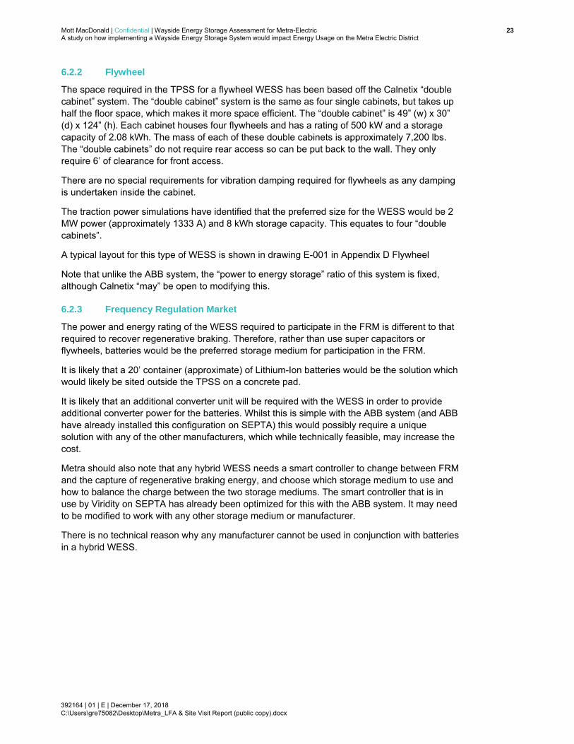
6.2.2 Flywheel
The space required in the TPSS for a flywheel WESS has been based off the Calnetix “double cabinet” system. The “double cabinet” system is the same as four single cabinets, but takes up half the floor space, which makes it more space efficient. The “double cabinet” is 49” (w) x 30” (d) x 124” (h). Each cabinet houses four flywheels and has a rating of 500 kW and a storage capacity of 2.08 kWh. The mass of each of these double cabinets is approximately 7,200 lbs. The “double cabinets” do not require rear access so can be put back to the wall. They only require 6’ of clearance for front access.
There are no special requirements for vibration damping required for flywheels as any damping is undertaken inside the cabinet.
The traction power simulations have identified that the preferred size for the WESS would be 2 MW power (approximately 1333 A) and 8 kWh storage capacity. This equates to four “double cabinets”.
A typical layout for this type of WESS is shown in drawing E-001 in Appendix D Flywheel
Note that unlike the ABB system, the “power to energy storage” ratio of this system is fixed, although Calnetix “may” be open to modifying this.
6.2.3 Frequency Regulation Market
The power and energy rating of the WESS required to participate in the FRM is different to that required to recover regenerative braking. Therefore, rather than use super capacitors or flywheels, batteries would be the preferred storage medium for participation in the FRM.
It is likely that a 20’ container (approximate) of Lithium-Ion batteries would be the solution which would likely be sited outside the TPSS on a concrete pad.
It is likely that an additional converter unit will be required with the WESS in order to provide additional converter power for the batteries. Whilst this is simple with the ABB system (and ABB have already installed this configuration on SEPTA) this would possibly require a unique solution with any of the other manufacturers, which while technically feasible, may increase the cost.
Metra should also note that any hybrid WESS needs a smart controller to change between FRM and the capture of regenerative braking energy, and choose which storage medium to use and how to balance the charge between the two storage mediums. The smart controller that is in use by Viridity on SEPTA has already been optimized for this with the ABB system. It may need to be modified to work with any other storage medium or manufacturer.
There is no technical reason why any manufacturer cannot be used in conjunction with batteries in a hybrid WESS.

Mott MacDonald | Confidential | Wayside Energy Storage Assessment for Metra-Electric 24A study on how implementing a Wayside Energy Storage System would impact Energy Usage on the Metra Electric District
392164 | 01 | E | December 17, 2018
C:\Users\gre75082\Desktop\Metra_LFA & Site Visit Report (public copy).docx
7 TPSS Site Survey Results
7.1 Site Visit
To identify the potential TPSS sites for the WESS Mott MacDonald and Facet Engineering undertook site visits to these TPSS. The site visits were conducted in order to ascertain if there would be sufficient room in each of the visited TPSS for the size of WESS required, and to identify if there are any unique constraints in each TPSS. The results and findings of the site surveys are presented in this section.
7.2 General
Wherever the WESS is installed, it will need a 125 V DC control power supply. It is highly probable that the existing batteries and charger will have the spare capacity for this additional load. For example, in the Matteson Substation, the battery charger is rated at 50 Amps, but the quiescent load is 5 Amps. This will need to be confirmed in the conceptual/detailed design, but Mott MacDonald considers it unlikely that the control power will need to be upgraded to support the WESS.
7.3 National Electrical Code
The equipment associated with the WESS will be installed in accordance with the National Electrical Code, City of Chicago Electrical Code, and Metra specifications. There is sufficient electrical/communication infrastructure (such as grounding, SCADA, power availability) to support the installation of the equipment in accordance with code.
Facet Engineering has examined the clearances for the equipment, both from code requirements, Metra maintenance requirements, and manufacturers recommendations. It has been determined that there are sufficient clearances from a code and manufacturer’s recommendations standpoint. Although Metra maintenance will need to be consulted to confirm the necessary clearances during the conceptual design for the chosen site.
Facet Engineering has confirmed that there is sufficient and code compliant ways for personnel to exit the facility with the new equipment installed.
7.4 Matteson TPSS
There are five (5) options for installing a WESS at Matteson TPSS. These are:
Outside the Substation in the northwest corner Outside the Substation in the location of the future transformer In the basement of the substation In the Substation along the west wall Inside the Substation
These different options are shown in drawings E-100 through to E-103 and are discussed below.
The first option is to install a 20’ container (approximate) containing the supercapacitor storage or flywheel storage located outside the substation in the northeast wall. This option would require for tree and foliage removal and the level grading of the ground. The container would be located on a concrete plinth with three overhead cable trays (traction power positive, traction

Mott MacDonald | Confidential | Wayside Energy Storage Assessment for Metra-Electric 25A study on how implementing a Wayside Energy Storage System would impact Energy Usage on the Metra Electric District
392164 | 01 | E | December 17, 2018
C:\Users\gre75082\Desktop\Metra_LFA & Site Visit Report (public copy).docx
power negative and LV/comms) into the main TPSS building. The proposed location is near an emergency access door and would require, to comply with NEC and Chicago Electric Code. This option can be seen on Drawing E-100 and refer to pictures M026, M027 and M028.
The second option is to install a 20’ container (approximate) containing the supercapacitor storage or flywheel storage located outside the substation in the location of the future transformer. This option would require existing fence sections to be removed for the proposed location of the container. A proposed new fence around the container with a 4-ft clearance would need to be constructed to close off the fenced transformer area, but it would protrude into the existing access road for the removal of the transformers. Therefore, this option would also require tree and foliage removal and the widening of the access road for sufficient clearance around the container. Similar to option 1, there would be three overhead cable trays into the main TPSS building. This option can be seen on Drawing E-101 and refer to pictures M022, M023, M024 and M025.
The third option is to locate the supercapacitor WESS in the basement of the substation. This option does not work for the flywheel as this is too tall to fit in the basement. The supercapacitor would be installed on a 3-inch thick concrete pad, but it would be extremely tight in terms of head height (requiring a modification to support side cable entry) and maneuvering and installing the equipment around existing cable trays and support beams. Additionally, possible water and dampness (even with a plinth) could lead to potential corrosion of the equipment. This option is therefore not considered suitable. This option can be seen on Drawing E-102.
The fourth option is to locate two flywheel WESS units along the northwest wall between rectifier 3 and ITC cabinet 2. This option would limit the total amount of potential energy storage due to reducing the flywheel equipment from 4 units to 2 units (refer to picture M001). A flammable cabinet would need to be relocated since it is currently shown in the working clearance space of the flywheel equipment (refer to picture M002). Although possible, this halves the storage capacity of the WESS and is not in an ideal location inside the substation. This option is therefore not considered suitable. This option can be seen on Drawing E-103.
The fifth option is to install a WESS inside the substation. MM has been informed by Metra that transformer and AC switchgear are being removed in future, which would leave enough space for a WESS to be installed inside the Substation. This would be the preferred option.
For all options a dedicated DC circuit breaker is required for the WESS. Mott MacDonald understands that the existing DC switchboard is due to be replaced shortly with the Siemens Sitras DSG equipment. It is therefore difficult to assess definitively if there is sufficient space for an additional DC circuit breaker for the WESS, but based on the present available space it does seem that there will be sufficient space in the TPSS for an additional DC circuit breaker.
Control power to the WESS will be from the 125V DC panel located on the east corner of the TPSS behind the DC switchboard.
The negative busbar is located in the cable basement which could require a new opening through the floor to get into the cable basement. This would need to be assessed in the preliminary design stage, but if necessary, coring a hole through the floor should not be too difficult.
7.5 Riverdale TPSS
Presently Riverdale TPSS is a Tie Station, but it is planned to be upgraded to a TPSS in the near future, with Mott MacDonald understanding that the majority of the design work having already been undertaken.

Mott MacDonald | Confidential | Wayside Energy Storage Assessment for Metra-Electric 26A study on how implementing a Wayside Energy Storage System would impact Energy Usage on the Metra Electric District
392164 | 01 | E | December 17, 2018
C:\Users\gre75082\Desktop\Metra_LFA & Site Visit Report (public copy).docx
Mott MacDonald believes that the upgrades will be similar to how 51st Street Tie Station was upgraded to a TPSS with a new modular building installed next to the existing brick building that contains the existing DC circuit breakers. The existing building and equipment are retained. The new modular building would contain the incoming HV power supply, HV circuit breakers, transformer rectifier, rectifier circuit breaker and then be cabled into the busbar of the existing DC switchboard.
In theory, it would be relatively easy to extend the module by approximately 25’ to include an additional DC circuit breaker and the WESS, but this depends on how far along the design is for the new module and how this extension would affect any planning permission as the TPSS backs onto a housing estate (refer to picture R010). Metra may be under pressure to keep the footprint of the module as small as possible or it may need the planning permission to be resubmitted.
There were no design drawings available to Mott MacDonald of the new module or where it would be located in relation to the existing building, the railway and the housing estate, making it impractical for Mott MacDonald to produce any updated drawings or sketches for this location. Refer to Drawing E-320 for the Riverdale Tie Station layout
Metra stated that work to upgrade Riverdale Tie Station to a TPSS has been advanced, so this site would be a non-starter.
7.6 51st Street TPSS
51st Street TPSS used to be a Tie Station that has been recently upgraded to a TPSS. This was achieved by installing a new AC modular building next to the existing brick building containing the existing DC circuit breakers, with the existing building and equipment being retained. The new AC modular building contains the incoming HV power supply, HV circuit breakers, transformer rectifiers, rectifier circuit breakers and then is cabled into the busbar of the existing DC switchboard.
This site presents a major problem in connecting the WESS into the 1500 V DC traction power supply as there is no room to install an additional circuit breaker in the existing DC switchboard or in the AC modular building. The options to connect into the DC traction power system are limited and would require the DC circuit breaker to be located with the WESS in the WESS container. The WESS could be connected using cables into the back of the rectifier DC circuit breaker in the AC modular building or the cables run to, and connected directly onto the OCS. Mott MacDonald does not know if it would be possible to connect into the back of the rectifier DC circuit breaker as the live compartment could not be opened for inspection during the site visit. Connecting directly to the OCS is also not without its own difficulty, and either option would have to be carefully considered in any future design. A similar problem also exists for the connection of the negative cables to / from the WESS.
There is also limited space on the site to install the WESS equipment, there are two (2) options for installing a WESS outside the TPSS, one is in front of the building and the second option is to install on south side of the building along the slope (refer to picture 5001). The container (approximately 20’ in length) would contain the new DC circuit breaker, a 125V DC panel for control power, supercapacitor storage or flywheel energy storage and other peripherals like lighting and fire alarm. The only available locations are outside the substation in the southwest corner parallel to S. Lake Park Avenue and on the south side of the building along the slope. The first option could require tree and foliage removal and the level grading of the ground as well as the installation of bollards to protect the container from road traffic (refer to pictures 5003 and 5004). This option can be seen on Drawing E-210. The second option would require

Mott MacDonald | Confidential | Wayside Energy Storage Assessment for Metra-Electric 27A study on how implementing a Wayside Energy Storage System would impact Energy Usage on the Metra Electric District
392164 | 01 | E | December 17, 2018
C:\Users\gre75082\Desktop\Metra_LFA & Site Visit Report (public copy).docx
additional civil work and this would add extra cost (refer to picture 5001). This option can be seen on Drawing E-211. These options would require coordination with the Chicago Department of Transportation (CDOT) and the Chicago Building Code for roadway clearances.
These problems would increase the cost of the WESS installation at this site and increase the difficulty of the construction and installation of the equipment.

Mott MacDonald | Confidential | Wayside Energy Storage Assessment for Metra-Electric 28A study on how implementing a Wayside Energy Storage System would impact Energy Usage on the Metra Electric District
392164 | 01 | E | December 17, 2018
C:\Users\gre75082\Desktop\Metra_LFA & Site Visit Report (public copy).docx
8 Conclusions and Recommendations
Based on our overall analysis, a WESS installed at Matteson, 51st Street or Riverdale TPSS would be the most efficient in capturing and redistributing regenerative currents and will result in the greatest total annual energy savings.
The preferred size and location of the WESS would be a 1000A 8 kWh WESS at Matteson TPSS which would save 396.4 MWh annually and provides for the minimum time to recover the installation costs. The ABB capacitor solution for a 1000 A, 8 kWh WESS, consists of two converter cabinets and four storage cabinets. Each cabinet costs approximately $125,000 so the total cost of the WESS will be $750,000, and an additional $100,000 (approximate) for the additional DC circuit breaker, module, and cabling, which brings the total cost of the installation to roughly $850,000. However, since Metra pays a discounted rate of $0.07 per kWh, this would only generate a $28,000 savings per year, with a return on investment of 30 years.
From a physical perspective the preferred sites for the WESS would be either the Matteson TPSS or Riverdale Tie Station (TPSS), as these sites have sufficient space for the WESS, though the suitability of Riverdale TPSS depends on what point the design is at in upgrading the site from a Tie Station to a TPSS, and whether the timescales for a WESS project can mesh with the timescales of the upgrade from a Tie Station to a TPSS.
Therefore, were Metra to go forward with installing a WESS, Mott MacDonald would recommend it to be installed at Matteson TPSS. Also MM has been informed by Metra that transformer and AC Switchgear are being removed in future which would leave enough space for the WESS to be installed inside the TPSS which would be preferred option.
With a ROI of 30 years, it is difficult to justify a WESS purely for financial reasons. This ROI is due to the relatively few trains during the off-peak on this corridor to make full use of the WESS, resulting in it sitting idle for approximately 50% of the time. If Metra is planning to increase the off-peak train frequency, then it may be possible for the recovered energy to increase to a level that would result in the return period dropping below 20 years, which would make the WESS financially viable. Alternatively, Metra may be able to obtain government assistance to reduce the initial cost of the WESS to Metra, which will also have the net effect of reducing the ROI period.
Note that either site could be suitable for participation in the FRM, but this is outside the scope of the study. Mott MacDonald would recommend that during any preliminary engineering design work for the WESS, the FRM option be explored to confirm if it is worth installing the additional batteries needed to participate in the FRM.

Mott MacDonald | Wayside Energy Storage Assessment for Metra-Electric 29 A study on how implementing a Wayside Energy Storage System would impact Energy Usage on the Metra Electric District
392164 | 01 | E | December 17, 2018 C:\Users\PAT85328\Desktop\Metra_LFA & Site Visit Report (public copy).docx
A. Electrical Resistance
1) Electrical Resistance (Refer to DC Protective Relay Setting Study Report for size and no of
wires)
a) Millennium to 63rd Street
Messenger wire (1) is sized as (13/16)”, 7 CW Wires, 12 Cu Wires which is 0.213 mΩ/m
(obtained from table 4 of electrical characteristics of copperweld/copper conductors
under 40% conductivity)
Auxiliary Messenger wire (1) is sized as 4/0 AWG which is 0.2 mΩ/m (obtained from
National Electrical Code book)
Contact wire (2) is sized as 4/0 AWG with 10% wear is 0.222 mΩ/m (obtained from
National Electrical Code book)
Total Resistance would be all resistance in parallel which comes out to 45.6 µΩ/m at
30º C.
b) 63rd to University Park, South Chicago, and Blue Island
Messenger wire (1) is sized as (13/16)”, 7 CW Wires, 12 Cu Wires which is 0.213 mΩ/m
(obtained from table 4 of electrical characteristics of copperweld/copper conductors
under 40% conductivity)
Auxiliary Messenger wire (1) is sized as 1/0 AWG which is 0.39 mΩ/m (obtained from
National Electrical Code book)
Contact wire (2) is sized as 4/0 AWG with 10% wear is 0.222 mΩ/m (obtained from
National Electrical Code book)
Total Resistance would be all resistance in parallel which comes out to 52.7 µΩ/m at
30º C.
c) NICTD Line
Messenger wire is 0.613 Type E copperweld composite wire which has a resistance of
0.05 Ω/1000ft at 68º F.
Contact wire is trolley wire 335 MCM alloy 80 which has a resistance of 0.03854
Ω/1000ft at 68º F.
Each track has a parallel feeder of 1000 MCM copper wire which has a resistance of
0.0423 Ω/km at 75º C.
This is an overall resistance of 24.26 µΩ/m at 30º C.
2) 115 lbs/yard Running Rail Resistance
a) Cross sectional area at 40º C with 5% wear is 11.0227 𝑖𝑛𝑐ℎ2
Standard value of Resistivity at 15º C is between 20 to 24.5 µΩ.cm
Resistance per length𝑅
𝐿=
𝜌
𝐴is between 28.12 µΩ/m to 33.74 µΩ/m at 15º C
For 40º C
𝑅2 = 𝑅1[1 + 𝛼(𝑇2 − 75 )]
Resistance per length is between 30.229 to 36.27 µΩ/m at 40º C

Mott MacDonald | Wayside Energy Storage Assessment for Metra-Electric 30 A study on how implementing a Wayside Energy Storage System would impact Energy Usage on the Metra Electric District
392164 | 01 | E | December 17, 2018 C:\Users\PAT85328\Desktop\Metra_LFA & Site Visit Report (public copy).docx
Since at Ambient Temperature 20º C Resistance per length is 15.67 µΩ/m
For 40º C assuming to be double 31.34 µΩ/m
31 Mott MacDonald | Chicago Metra Load Flow Analysis A study on how implementing a Wayside Energy Storage System would impact Energy Usage on the Metra Electric District
392164 | 01 | E | December 17, 2018 C:\Users\PAT85328\Documents\RTA\Final version\report\Metra_LFA & Site Visit Report.docx
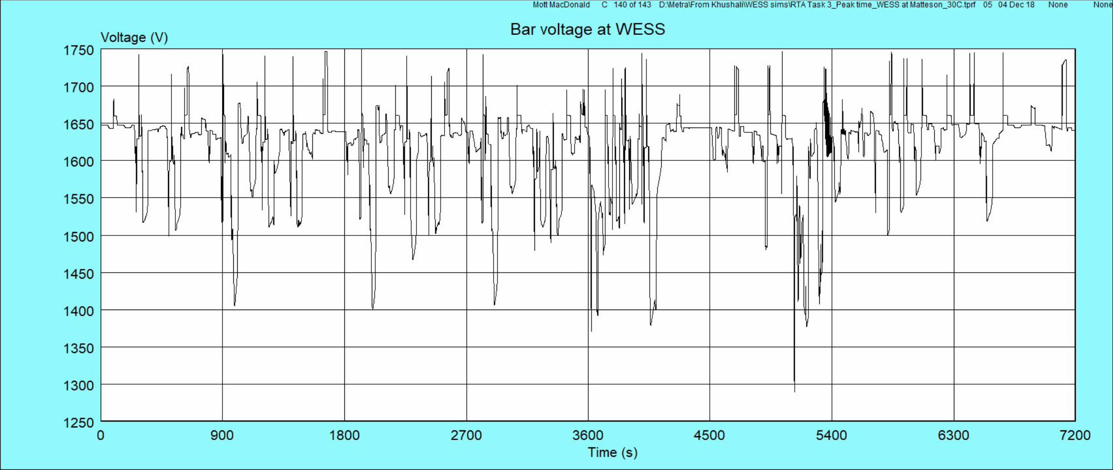
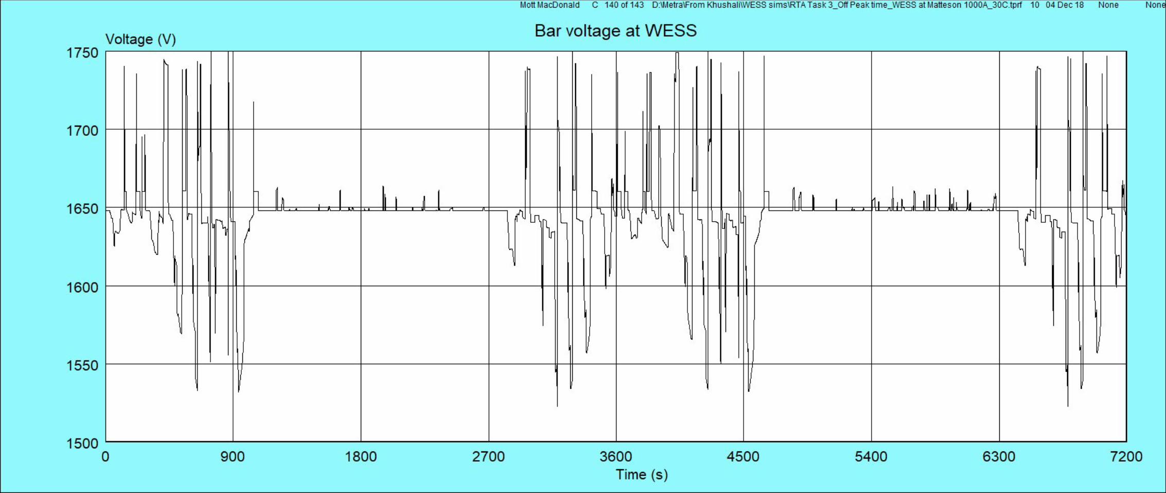
B. Plots
Matteson TPSS with 2000 A 8 kWh WESS
Peak Time
Off-peak Time
Matteson TPSS with 1000 A 8 kWh WESS
Peak Time
Off-peak Time
51st Street TPSS with 2000 A 8 kWh WESS
Peak Time
Off-peak Time
Riverdale TPSS with 2000 A 8 kWh WESS
Peak Time
Off-peak Time


Mott MacDonald | Wayside Energy Storage Assessment for Metra-Electric 56A study on how implementing a Wayside Energy Storage System would impact Energy Usage on the Metra Electric District
392164 | 01 | E | December 17, 2018 C:\Users\PAT85328\Desktop\Metra_LFA & Site Visit Report (public copy).docx
C. Manufacturer’s Information
Drawings have been removed

57Mott MacDonald | Chicago Metra Load Flow Analysis A study on how implementing a Wayside Energy Storage System would impact Energy Usage on the Metra Electric District
392164 | 01 | E | December 17, 2018 C:\Users\PAT85328\Documents\RTA\Final version\Metra_LFA & Site Visit Report.docx
D. Marked up TPSS Layout Drawings
Drawings have been removed

Mott MacDonald | Chicago Metra Load Flow Analysis 58A study on how implementing a Wayside Energy Storage System would impact Energy Usage on the Metra Electric District
392164 | 01 | E | December 17, 2018 C:\Users\PAT85328\Documents\RTA\Final version\report\Metra_LFA & Site Visit Report.docx
E. Photos for Matteson TPSS
Photos have been removed

Mott MacDonald | Chicago Metra Load Flow Analysis 59A study on how implementing a Wayside Energy Storage System would impact Energy Usage on the Metra Electric District
392164 | 01 | E | December 17, 2018 C:\Users\PAT85328\Documents\RTA\Final version\report\Metra_LFA & Site Visit Report.docx
F. Photos for 51st Street TPSS
Photos have been removed

Mott MacDonald | Chicago Metra Load Flow Analysis 60A study on how implementing a Wayside Energy Storage System would impact Energy Usage on the Metra Electric District
392164 | 01 | E | December 17, 2018 C:\Users\PAT85328\Documents\RTA\Final version\report\Metra_LFA & Site Visit Report.docx
G. Photos for Riverdale TPSS
Photos have been removed