WAYNE-DALTON - · PDF fileWAYNE-DALTON EMERGENCY EGRESS ... ELECTRICAL TRANSFORMER:. . . . . ....
20
WAYNE-DALTON EMERGENCY EGRESS GRILLE OPERATOR EES SERIES NOT FOR RESIDENTIAL USE LMPLC CONTROL LMPLC B2/C2 Wiring CONTROL WIRED Serial # Box Installation Date 2 YEAR WARRANTY
Transcript of WAYNE-DALTON - · PDF fileWAYNE-DALTON EMERGENCY EGRESS ... ELECTRICAL TRANSFORMER:. . . . . ....
WAYNE-DALTONEMERGENCY EGRESS
GRILLE OPERATOREES SERIES
NOT FOR RESIDENTIAL USE
LMPLC CONTROLLMPLC
B2/C2 Wiring
C O N T R O L W I R E D
Serial # Box
Installation Date
2 Y E A R W A R R A N T Y

2
When you see these Safety Symbols and Signal Words on the following pages, they will alert you to the possibility of serious injury or death if you do not comply with the warnings that accompany them. The hazard may come from something mechanical or from electric shock. Read the warnings carefully.When you see this Signal Word on the following pages, it will alert you to the possibility of damage to your door and/or the door operator if you do not comply with the cautionary statements that accompany it. Read them carefully.
Mechanical
Electrical
T A B L E O F C O N T E N T S
ATTENTION
AVERTISSEMENT AVERTISSEMENT
AVERTISSEMENT
WARNING WARNING
CAUTION
WARNING
WARNING
PRECAUCIÓN ADVERTENCIA
ADVERTENCIA ADVERTENCIA
ATTENTION
AVERTISSEMENT AVERTISSEMENT
AVERTISSEMENT
WARNING
CAUTION
WARNING WARNING
WARNING
PRECAUCIÓN ADVERTENCIA
ADVERTENCIA ADVERTENCIA
ATTENTION
AVERTISSEMENT AVERTISSEMENT
AVERTISSEMENT
WARNING
CAUTION CAUTION
WARNING
WARNING
PRECAUCIÓN ADVERTENCIA
ADVERTENCIA ADVERTENCIA
SPECIFICATIONSOperator Specifications. . . . . . . . . . . . . . . . . . . . . . . . . . . . . . . . . 3Operator Dimensions . . . . . . . . . . . . . . . . . . . . . . . . . . . . . . . . . . 3
THEORY OF OPERATIONGeneral Description . . . . . . . . . . . . . . . . . . . . . . . . . . . . . . . . . . . 4
INSTALLATIONOperator Mounting . . . . . . . . . . . . . . . . . . . . . . . . . . . . . . . . . . . . 5Entrapment Protection Accessories . . . . . . . . . . . . . . . . . . . . . . . 6FCC Warning. . . . . . . . . . . . . . . . . . . . . . . . . . . . . . . . . . . . . . . . . 6
ADJUSTMENTLimit Switch Adjustment. . . . . . . . . . . . . . . . . . . . . . . . . . . . . . . . 7Brake Adjustment . . . . . . . . . . . . . . . . . . . . . . . . . . . . . . . . . . . . . 7
POWER WIRING & GROUND WIRING
Important Safety Warnings. . . . . . . . . . . . . . . . . . . . . . . . . . . . . . 8Power Wiring Connections . . . . . . . . . . . . . . . . . . . . . . . . . . . . . . 8Ground Wiring Connections . . . . . . . . . . . . . . . . . . . . . . . . . . . . . 8
CONTROL STATION WIRING & INSTALLATION
Important Safety Warnings. . . . . . . . . . . . . . . . . . . . . . . . . . . . . . 9Control Station Wiring . . . . . . . . . . . . . . . . . . . . . . . . . . . . . . . . . 9Mounting Instructions . . . . . . . . . . . . . . . . . . . . . . . . . . . . . . . . . 9
DIAGRAMSStandard Power and Control Connection Diagrams . . . . . . . . . . 10Logic Board Illustration . . . . . . . . . . . . . . . . . . . . . . . . . . . . . . . 11Optional Control Settings . . . . . . . . . . . . . . . . . . . . . . . . . . . . . . 121 Phase Wiring Diagram. . . . . . . . . . . . . . . . . . . . . . . . . . . . . . . 133 Phase Wiring Diagram. . . . . . . . . . . . . . . . . . . . . . . . . . . . . . . 14
MAINTENANCE SCHEDULE / CONTACT INFORMATION . . . . . . . . . . . . . . . . . . . . . . . . . . 15
REPAIR PARTSRepair Parts Kits - EES5011(L/R) & EES5021(L/R) . . . . . . . . . . 16Illustrated Parts - EES5011(L/R) & EES5021(L/R) . . . . . . . . . . . 17Repair Parts Kits - EES1023(L/R) & EES1043(L/R) . . . . . . . . . . 18Illustrated Parts - EES1023(L/R) & EES1043(L/R) . . . . . . . . . . . 19
CONTROL CONNECTION DIAGRAM . . . . . . . . . . . . . . . . . 20
IMPORTANT NOTES:• BEFORE attempting to install, operate or maintain the operator,
you must read and fully understand this manual and follow all safety instructions.
• DO NOT attempt repair or service of your commercial door and operator unless you are an Authorized Service Technician.
SAVE THESE INSTRUCTIONS

DRIVE REDUCTION 1/2 HP: . . . . . 50:1 Reduction In Line Gear Reduced Motor.
DRIVE REDUCTION 1 HP:. . . . . . . 56:1 Reduction In Line Gear Reducer
MAX. BACK DRIVING FORCE . . . . 140 in-lbs.
OUTPUT SHAFT SPEED: . . . . 1/2 HP (30 RPM) & 1 HP (35 RPM)DOOR SPEED 1/2 & 1 HP: . . 12" per second depending on doorBRAKE: . . . . . . . . . . . . . . . . . Solenoid actuated disc brake
3
MOTORTYPE: . . . . . . . . . . . . . . . . . . . . . . Continuous dutyHORSEPOWER: . . . . . . . . . . . . . . 1/2 HP
1 HPSPEED: . . . . . . . . . . . . . . . . . . . . . 1725 RPMVOLTAGE: . . . . . . . . . . . . . . . . . . . 115/230 1 Phase
230/460 3 PhaseCURRENT: . . . . . . . . . . . . . . . . . . 115/230 Volt = 8.4/4.2A
230/460 Volt = 3.6/1.8A
ELECTRICALTRANSFORMER:. . . . . . . . . . 24 VAC, 75 VACONTROL STATION: . . . . . . . NEMA 3-Button Station
OPEN/CLOSE/STOPWIRING TYPE: . . . . . . . . . . C2 (Standard)/B2 (Optional)
To convert to B2 see pages 13 & 14 note 2.
LIMIT ADJUST: . . . . . . . . . . . Linear driven, fully adjustable screw type cams. 70 revolutions maximum at limit shaft.
FUSE: . . . . . . . . . . . . . . . . . . 250V, 3AG, 2 AMP Slow-blow.
MOUNTING DIMENSIONS
MOUNTING DIMENSIONS
DIMENSIONS 1/2 HP
DIMENSIONS 1 HP
S P E C I F I C A T I O N S
MECHANICAL
13.99"
4.83"
14.19"
3.15"
22.28"
2.95"3.35"
3.35"
4.53"
0.35" x 0.55" Slot(4 places)
15.81"
0.44" Holes (2 places)
2.81"5.62"
11.28"
15.81"12.46"
14.04
15.4 MAX.
5.61
7.20 MAX
4.40 MAX.
4.33
24 MAX.
5.61
3.94
16.69
5.61
20.23
A
8.58
8.58
2.88 3.94
1.67"
4
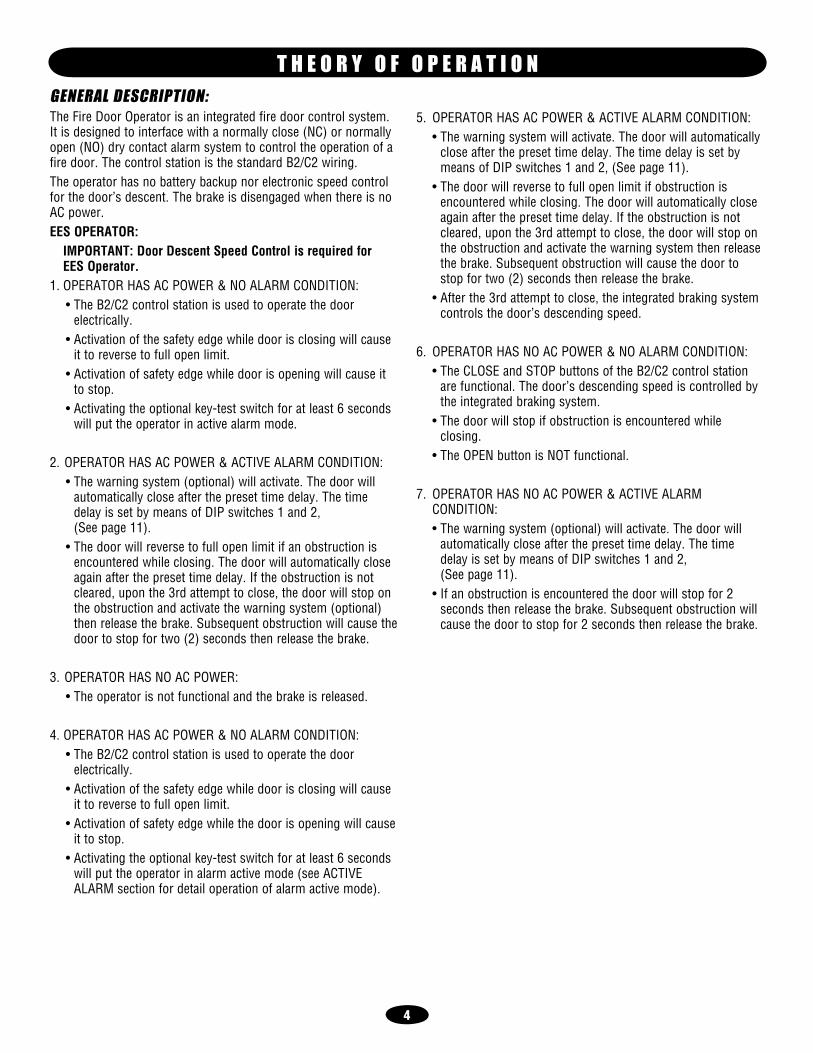
5. OPERATOR HAS AC POWER & ACTIVE ALARM CONDITION: • The warning system will activate. The door will automatically
close after the preset time delay. The time delay is set by means of DIP switches 1 and 2, (See page 11).
• The door will reverse to full open limit if obstruction is encountered while closing. The door will automatically close again after the preset time delay. If the obstruction is not cleared, upon the 3rd attempt to close, the door will stop on the obstruction and activate the warning system then release the brake. Subsequent obstruction will cause the door to stop for two (2) seconds then release the brake.
• After the 3rd attempt to close, the integrated braking system controls the door’s descending speed.
6. OPERATOR HAS NO AC POWER & NO ALARM CONDITION: • The CLOSE and STOP buttons of the B2/C2 control station
are functional. The door’s descending speed is controlled by the integrated braking system.
• The door will stop if obstruction is encountered while closing.
• The OPEN button is NOT functional.
7. OPERATOR HAS NO AC POWER & ACTIVE ALARM CONDITION:
• The warning system (optional) will activate. The door will automatically close after the preset time delay. The time delay is set by means of DIP switches 1 and 2, (See page 11).
• If an obstruction is encountered the door will stop for 2 seconds then release the brake. Subsequent obstruction will cause the door to stop for 2 seconds then release the brake.
GENERAL DESCRIPTION:The Fire Door Operator is an integrated fire door control system. It is designed to interface with a normally close (NC) or normally open (NO) dry contact alarm system to control the operation of a fire door. The control station is the standard B2/C2 wiring.The operator has no battery backup nor electronic speed control for the door’s descent. The brake is disengaged when there is no AC power. EES OPERATOR: IMPORTANT: Door Descent Speed Control is required for
EES Operator.1. OPERATOR HAS AC POWER & NO ALARM CONDITION: • The B2/C2 control station is used to operate the door
electrically. • Activation of the safety edge while door is closing will cause
it to reverse to full open limit. • Activation of safety edge while door is opening will cause it
to stop. • Activating the optional key-test switch for at least 6 seconds
will put the operator in active alarm mode.
2. OPERATOR HAS AC POWER & ACTIVE ALARM CONDITION: • The warning system (optional) will activate. The door will
automatically close after the preset time delay. The time delay is set by means of DIP switches 1 and 2, (See page 11).
• The door will reverse to full open limit if an obstruction is encountered while closing. The door will automatically close again after the preset time delay. If the obstruction is not cleared, upon the 3rd attempt to close, the door will stop on the obstruction and activate the warning system (optional) then release the brake. Subsequent obstruction will cause the door to stop for two (2) seconds then release the brake.
3. OPERATOR HAS NO AC POWER: • The operator is not functional and the brake is released.
4. OPERATOR HAS AC POWER & NO ALARM CONDITION: • The B2/C2 control station is used to operate the door
electrically. • Activation of the safety edge while door is closing will cause
it to reverse to full open limit. • Activation of safety edge while the door is opening will cause
it to stop. • Activating the optional key-test switch for at least 6 seconds
will put the operator in alarm active mode (see ACTIVE ALARM section for detail operation of alarm active mode).
T H E O R Y O F O P E R A T I O N

5
OPERATOR MOUNTING1. Wall Mount: The operator should generally be installed below
the door shaft, and as close to the door as possible (Figure 1).Bracket Shelf Mounting: The operator may be mounted either above or below the door shaft (Figure 2).
IMPORTANT: The shelf or bracket must provide adequate support, prevent play between operator and door shaft, and permit operator to be fastened securely and with the drive shaft parallel to the door shaft.NOTE: The optimum distance between the door shaft and operator drive shaft is between 12" - 15".2. Place door sprocket on the door shaft. Do not insert the key at
this time.3. Place drive sprocket on the appropriate side of the operator.
Do not insert the key at this time.4. Wrap drive chain around door sprocket and join roller chain
ends together with master link.5. Raise operator to approximate mounting position and position
chain over operator sprocket.6. Raise or lower operator until the chain is taut (not tight). Make
sure the operator output shaft is parallel to door shaft and sprockets are aligned. When in position, secure the operator to wall or mounting bracket (Figure 3).
7. Align sprockets and secure.
FIGURE 1
FIGURE 2
Before your operator is installed, be sure the door has been properly aligned and is working smoothly. The operator may be wall mounted or mounted on a bracket or shelf. Refer to the illustration and instructions below that suits your application.
I N S T A L L A T I O N
To prevent possible SERIOUS INJURY or DEATH:• DO NOT connect electric power until instructed to do so.• If the door lock needs to remain functional, install an
interlock switch.• ALWAYS call a trained professional door serviceman if door
binds, sticks or is out of balance. An unbalanced door may not reverse when required.
• NEVER try to loosen, move or adjust doors, door springs, cables, pulleys, brackets or their hardware, ALL of which are under EXTREME tension and can cause SERIOUS PERSONAL INJURY.
• Disable ALL locks and remove ALL ropes connected to door BEFORE installing and operating door operator to avoid entanglement.
• To prevent possible SERIOUS INJURY or DEATH from a falling door, ALL doors intended to be motor operated should be manufactured with solid door shafts.
FIGURE 3
(Right-Hand Wall Mount Shown) (Left-Hand Wall Mount Shown)
(Right-Hand Hood Mount Shown) (Left-Hand Hood Mount Shown)
ATTENTION
AVERTISSEMENT AVERTISSEMENT
AVERTISSEMENT
WARNING
CAUTION
WARNING
WARNING WARNING
PRECAUCIÓN ADVERTENCIA
ADVERTENCIA ADVERTENCIA
6
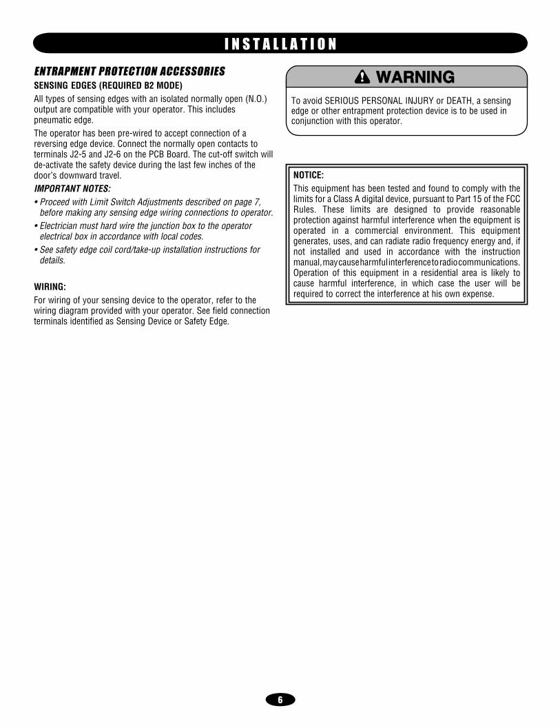
ENTRAPMENT PROTECTION ACCESSORIESSENSING EDGES (REQUIRED B2 MODE)All types of sensing edges with an isolated normally open (N.O.) output are compatible with your operator. This includes pneumatic edge.The operator has been pre-wired to accept connection of a reversing edge device. Connect the normally open contacts to terminals J2-5 and J2-6 on the PCB Board. The cut-off switch will de-activate the safety device during the last few inches of the door’s downward travel.IMPORTANT NOTES:• Proceed with Limit Switch Adjustments described on page 7,
before making any sensing edge wiring connections to operator.• Electrician must hard wire the junction box to the operator
electrical box in accordance with local codes.• See safety edge coil cord/take-up installation instructions for
details.
WIRING:For wiring of your sensing device to the operator, refer to the wiring diagram provided with your operator. See field connection terminals identified as Sensing Device or Safety Edge.
I N S T A L L A T I O N
To avoid SERIOUS PERSONAL INJURY or DEATH, a sensing edge or other entrapment protection device is to be used in conjunction with this operator.
ATTENTION
AVERTISSEMENT AVERTISSEMENT
AVERTISSEMENT
WARNING WARNING
CAUTION
WARNING
WARNING
PRECAUCIÓN ADVERTENCIA
ADVERTENCIA ADVERTENCIA
NOTICE: This equipment has been tested and found to comply with the limits for a Class A digital device, pursuant to Part 15 of the FCC Rules. These limits are designed to provide reasonable protection against harmful interference when the equipment is operated in a commercial environment. This equipment generates, uses, and can radiate radio frequency energy and, if not installed and used in accordance with the instruction manual, may cause harmful interference to radio communications. Operation of this equipment in a residential area is likely to cause harmful interference, in which case the user will be required to correct the interference at his own expense.

7
If other problems persist, see contact information on page 15.
LIMIT SWITCH ADJUSTMENTNOTE: Make sure the limit nuts are positioned between the limit switch actuators before proceeding with adjustments.1. Depress retaining plate to allow nut to spin freely. After
adjustment, release plate and move nut back and forth to ensure it is fully seated in slot.
2. To increase door travel, spin nut away from actuator. To decrease door travel, spin limit nut toward actuator.
3. Adjust open limit nut so that door will stop in open position with the bottom of the door even with top of door opening.
4. Repeat Steps 1 and 2 for close cycle. Adjust close limit nut so that actuator is engaged as door fully seats at the floor.
Retaining Plate
CLOSE Limit Switch
SAFETY(Aux. Close) Limit Switch
OPEN Limit Switch
Actuator
BRAKE ADJUSTMENTThe brake is adjusted at the factory and should not need additional adjustment for the life of the friction pad. Replace friction pads when necessary. Refer to the illustrations on pages 16 & 18 for identification of components for the solenoid type brake system.
Brake Pad
RPM Board
Rotator Cup
A D J U S T M E N T
To avoid SERIOUS PERSONAL INJURY or DEATH from electrocution, disconnect electric power BEFORE manually moving limit nuts.
ATTENTION
AVERTISSEMENT AVERTISSEMENT
AVERTISSEMENT
WARNING
CAUTION
WARNING WARNING
WARNING
PRECAUCIÓN ADVERTENCIA
ADVERTENCIA ADVERTENCIA

8
7/8" Power Wiring Access Hole(On Either Side)
7/8" ControlWiring Access Hole (On Either Side)
Remove the cover from the electrical enclosure. Inside this enclosure you will find the wiring diagram(s) for your operator. Refer to the diagram (glued on the inside of the cover) for all connections described below. If this diagram is missing, see contact information on page 15.
POWER WIRING CONNECTIONS1. Be sure that the power supply is of the correct voltage, phase,
frequency, and amperage to supply the operator. Refer to the operator nameplate on the cover.
2. Using the 7/8" conduit access knockout as shown, bring supply lines to the operator and connect wires to the terminals indicated on the WIRING CONNECTIONS DIAGRAM.
NOTES:• Do not turn power on until you have finished making all power
and control wiring connections and have completed the limit switch adjustment procedure.
• On three phase machines ONLY, incorrect phasing of the power supply will cause the motor to rotate in the wrong direction (open when CLOSE button is pressed and vice-versa). To correct this, interchange any two of the incoming three phase power lines with power off.
GROUND WIRING CONNECTIONS1. Connect earth ground to the chassis ground screw in the
electrical box enclosure.2. Use same conduit entry into the electrical box as the power
wiring.IMPORTANT NOTE: This operator must be properly grounded. Failure to properly ground this operator could result in electric shock and serious injury.
P O W E R W I R I N G & G R O U N D W I R I N G
To reduce the risk of SEVERE INJURY or DEATH:• DISCONNECT and LOCK-OUT power BEFORE installation or
performing ANY maintenance to the operator or in the area near the operator. Upon completion of maintenance the area MUST be cleared and secured BEFORE returning the operator to service.
• Operator MUST be properly grounded and connected in accordance with local electrical codes. The operator should be on a separate fused line of adequate capacity.
• Operator MUST be permanently wired as per NFPA 70 (National Electrical Code) ground MUST be pulled with each service. Service voltage MUST be run separately from class 2 circuits.
• ALL electrical connections MUST be made by a qualified individual.
• DO NOT install ANY wiring or attempt to run the operator without consulting the wiring diagram. It is required you install a reversing edge BEFORE proceeding with the control station installation. (Although suggested, optional in C2 mode.)
• ALL power wiring should be on a dedicated circuit and well protected. The location of the power disconnect should be visible and clearly labeled.
• ALL power and control wiring MUST be run in separate conduit.
• To avoid damage to door and operator, make ALL door locks inoperative. Secure lock(s) in “open” position. If the door lock needs to remain functional, install an interlock switch.
ATTENTION
AVERTISSEMENT AVERTISSEMENT
AVERTISSEMENT
WARNING
CAUTION
WARNING
WARNING WARNING
PRECAUCIÓN ADVERTENCIA
ADVERTENCIA ADVERTENCIA

9
IMPORTANT NOTE: ALL inputs MUST be dry contact only! This includes: alarm inputs, control inputs, sensing edges and sensing devices. For any other devices not mentioned, please consult the factory.
CONTROL STATION WIRINGRefer to Control Connection Diagrams on pages 10 & 20. Make connection through hole labeled for control. Be sure to use the control box opening with the 7/8" knockout for CONTROL cable(s). All power wires use the 1-1/16" knockout. Do not run control wires in the same conduit as power wires.1. Complete electrical connections to the operator and the control
station. Fasten the control station to the wall and MOUNT THE WARNING NOTICE BESIDE OR BELOW THE PUSH BUTTON STATION.
2. Apply power to the operator. Press OPEN push button and observe direction of door movement and then press the STOP button.
If door did not move in the correct direction, check for improper wiring at the control station or between operator and control station.
If the operator is three phase and control station wiring is correct, exchange any two of the three incoming power leads.
If electrical problems persist, see contact information on page 15.
MOUNTING INSTRUCTIONS1. Mount Control Stations no further than (12") from each other.2. Mount Control Stations (12") from the door enclosure.3. Mount WARNING NOTICE beside or below the Control Station.
W A R N I N GTO PREVENT ENTRAPMENT
DO NOT START DOOR DOWNWARDUNLESS DOORWAY IS CLEAR
NEPOPEN
ESOLCLOSE
POTSSTOP
W A R N I N GOPEN
CLOSE
C O N T R O L S T A T I O N W I R I N G A N D I N S T A L L A T I O N
To reduce the risk of SEVERE INJURY or DEATH:• Install the control station where the door is visible, but away
from the door and its hardware. If control station CANNOT be installed where door is visible, or if ANY device other than the control station is used to activate the door, a reversing edge MUST be installed on the bottom of the door. Failure to install a reversing edge under these circumstances may result in SERIOUS INJURY or DEATH to persons trapped beneath the door.
• To avoid damage to door and operator, make ALL door locks inoperative. Secure lock(s) in “open” position. If the door lock needs to remain functional, install an interlock switch.
• Disconnect power at fuse box BEFORE proceeding.• Service voltage MUST be run separately from class 2 circuits
(controls).• ALL electrical connections MUST be made by a qualified
individual.• DO NOT install ANY wiring or attempt to run the operator
without consulting the wiring diagram. It is required you install a reversing edge BEFORE proceeding with the control station installation. (Although suggested, optional in C2 mode.)
Control Station
Push Buttons
WARNING Notice
ATTENTION
AVERTISSEMENT AVERTISSEMENT
AVERTISSEMENT
WARNING
CAUTION
WARNING
WARNING WARNING
PRECAUCIÓN ADVERTENCIA
ADVERTENCIA ADVERTENCIA

10
LMPLC BOARD - 230V, 460V 3PH
J2
1 2 3 4 5 6 7 8 9 10 11 12
13 14 15 16 17 18 19 20 21 22 23 24
J1
L1 L2 L3
GREENGROUNDSCREWOPEN
CLOSE
STOP
REVERSEEDGE 230/460V 3PH.
POWER IN
CHASSIS GROUND
J2
1 2 3 4 5 6 7 8 9 10 11 12
13 14 15 16 17 18 19 20 21 22 23 24
J1
L1 L2 L3
GREENGROUNDSCREW
OPEN
CLOSE
STOP
REVERSEEDGE
HOT
NEUTRAL
CHASSIS GROUND
S T A N D A R D P O W E R & C O N T R O L C O N N E C T I O N D I A G R A M S
NOTE: The operator should be on a separate fused line of adequate capacity.
Operator must be permanently wired as per NFPA 70 (National Electrical Code). Ground must be pulled with each service. Service voltage must be run SEPARATELY from class 2 circuits (controls).
LMPLC BOARD - 115V/230V 1PH

11
Terminal Block (J1)
Heat Sink
Dip Switches (S1)
L O G I C B O A R D I L L U S T R A T I O N
Terminal Block (J2)
NOTE: For DIP switch field settings, see page 12.

12
1 2 3 4
ON
OFF 1 2 3 4
ON
OFF
1 2 3 4
ON
OFF 1 2 3 4
ON
OFF
1 2 3 4
ON
OFF 1 2 3 4
ON
OFF
NOTE: All functions are independent of each other and do not require other control settings to be set at any certain configuration. SWITCH 4 IS NOT USED BUT MUST BE SET IN THE OFF POSITION IN ORDER FOR THE OPERATOR TO WORK PROPERLY. For dip switch location and orientation refer to illustration on page 11.
ALARM DELAY TO CLOSES1,1 and S1,2 set the Alarm Delay to Close time of the operator. Alarm Delay to Close is the time between when the operator first receives an active alarm signal and the door starts to close. Refer to illustrations below for various settings.
10 SECOND DELAY 30 SECOND DELAY
45 SECOND DELAY 60 SECOND DELAY
N.O. ALARM N.C. ALARM
FIRE ALARM SYSTEMSelect the alarm system being used. If the alarm is a normally open system then S1,3 must be off. If the alarm is a normally close system then S1,3 must be on.
O P T I O N A L C O N T R O L S E T T I N G S
13
(GY)
(BK)(BL)(BK)
(PU)(YE)
T2
T4
T5
T3T1
T8
115V MOTOR CONNECTION 230V MOTOR CONNECTION
(GY)(BK)
(BK)(PU)
(YE)
T2
T4
T5T3
T1
T8
(YE)
(WH)
(RD)
(WH)
SAFETYLIMIT SW.
CLOSELIMIT SW.
NCNO
NCNO
(WH)
(BL)NCNO
OPENLIMIT SW.
MOTORC
EKAR
BCD
DION
ELOS
CHASSISGROUND
(BL)-
(RD)+
J30 J17
J3 J4
S1J14
J15
J13
13 14 15 16 17 18 19 20 21 22 23 24
1 2 3 4 5 6 7 8 9 10 11 12
J16
J18 J19
ZILOG PROCESSOR(BK)
(BK)
FUSE
2 AMP
(BR)J12
J9
J8(OR)(RD)
(BR)
J5
(YE)
J24
(GY)
(PU)
J23
J6
J7
(OR)
(YE)(BL)
J25
J28
J20
(BL)
J29J1L1 L2 L3
J22J26
J27
(BK) (BK)
BREAKER
115/230V 1PHPOWER IN
TO ALARMSYSTEM
TRANSFORMER
(WH)
(BK)
YRAMIRP
YRADNOCES
OPTIONAL USERINTERFACE
(BR)
(BR)
SEE NOTE 4 REVERSEEDGE
C NOKEY-TEST
OPEN
CLOSE
STOP
VOICEBOARD
(PU) (BK)
(RD)(YE)
SPEAKERAUXILIARYTERMINALBLOCK
+ (RD)
- (BK)
250 MAMAX
(BR)
(PU)
(YE)
STROBE LIGHT 24V
(BK)
(BL)
(PU)
(GY)
(YE)
(BK)
C
C
_
+
115VONLY
J21
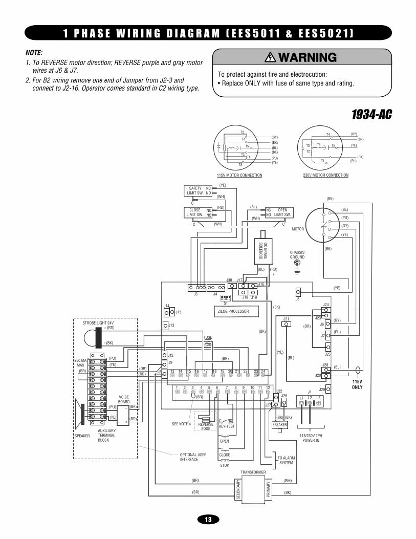
1 P H A S E W I R I N G D I A G R A M ( E E S 5 0 1 1 & E E S 5 0 2 1 )
NOTE:1. To REVERSE motor direction; REVERSE purple and gray motor
wires at J6 & J7.2. For B2 wiring remove one end of Jumper from J2-3 and
connect to J2-16. Operator comes standard in C2 wiring type.
To protect against fire and electrocution:• Replace ONLY with fuse of same type and rating.
ATTENTION
AVERTISSEMENT AVERTISSEMENT
AVERTISSEMENT
WARNING
CAUTION
WARNING WARNING
WARNING
PRECAUCIÓN ADVERTENCIA
ADVERTENCIA ADVERTENCIA
1934-AC

14
1936-AC460V - 3 PH
MOTOR CONNECTION
INTERNAL MOTOR CONNECTIONS
8
9
7
(BN)
(PU)
(YE)
(BN)
(GY)
3
2
14
5
6
230V - 3 PHMOTOR CONNECTION
1
2
3
8
9
7
6
5
4
(YE)
(BN)
(GY)
(BN)
(PU)
(BR)
(YE)
(WH)
(RD)
(WH)
SAFETYLIMIT SW.
CLOSELIMIT SW.
NCNO
NCNO (WH)
(BL)NCNO
OPENLIMIT SW.
MOTOR
C
EKAR
BCD
DION
ELOS CHASSIS
GROUND
(BL)-
(RD)+
J30 J17
J3 J4
S1J14
J15
J13
13 14 15 16 17 18 19 20 21 22 23 24
1 2 3 4 5 6 7 8 9 10 11 12
J16
J18 J19
ZILOG PROCESSOR(BK)
(BK)FUSE
2 AMP
(BR)J12
J9
J8(OR)
(RD)
(BR)
J5
(YE)
J24
(GY)
(PU)J23J6
J7
J25
J28
J20
J29J1
L1 L2 L3J22
J26
J27
(BL)230/460V 3PH.
POWER IN
TO ALARMSYSTEM
TRANSFORMER
(WH)
(BK)
YRAMIRP
YRADNOCES
OPTIONAL USERINTERFACE
(BR)
(BR)
SEE NOTE 4 REVERSEEDGE
C NOKEY-TEST
OPEN
CLOSE
STOP
VOICEBOARD
(PU) (BK)
(RD)(YE)
SPEAKERAUXILIARYTERMINALBLOCK
+ (RD)
- (BK)
250 MAMAX
(BR)
(PU)(YE)
STROBE LIGHT 24V
C
C
_
+
J21
(BK)
(BK)
(BK)
(BK)
T3
T2
T1
(BK)
(BK)
(BK)
95
96
L3 T3
L2 T2
L1 T1
(BK)
3 P H A S E W I R I N G D I A G R A M ( E E S 1 0 2 3 & E E S 1 0 4 3 )
NOTE:1. To REVERSE motor direction; REVERSE purple and gray motor
wires at J6 & J7.2. For B2 wiring remove one end of Jumper from J2-3 and
connect to J2-16.
To protect against fire and electrocution: • Replace ONLY with fuse of same type and rating.
ATTENTION
AVERTISSEMENT AVERTISSEMENT
AVERTISSEMENT
WARNING
CAUTION
WARNING WARNING
WARNING
PRECAUCIÓN ADVERTENCIA
ADVERTENCIA ADVERTENCIA

EVERY EVERY EVERY EVERY ITEM PROCEDURE 3 MONTHS 6 MONTHS 12 MONTHS 24 MONTHS Drive Chain Check for excessive slack
Check and adjust as requiredLubricate
Sprockets Check set screw tightness Fasteners Check and tighten as required Bearings and Shafts Check for wear and lubricate Battery Maintenance Replace batteries
15
Use SAE 30 Oil (Never use grease or silicone spray).
Repeat ALL procedures. Do not lubricate motor. Motor bearings are rated for continuous operation.
Inspect and service whenever a malfunction is observed or suspected.
Check at the intervals listed in the following chart:
M A I N T E N A N C E S C H E D U L E
HOW TO ORDER REPAIR PARTSFor installation and service information
Call our TOLL FREE number:1-800-255-3046
To avoid SERIOUS PERSONAL INJURY or DEATH from electrocution, disconnect ALL electric power BEFORE performing ANY maintenance.
ATTENTION
AVERTISSEMENT AVERTISSEMENT
AVERTISSEMENT
WARNING
CAUTION
WARNING
WARNING WARNING
PRECAUCIÓN ADVERTENCIA
ADVERTENCIA ADVERTENCIA
16
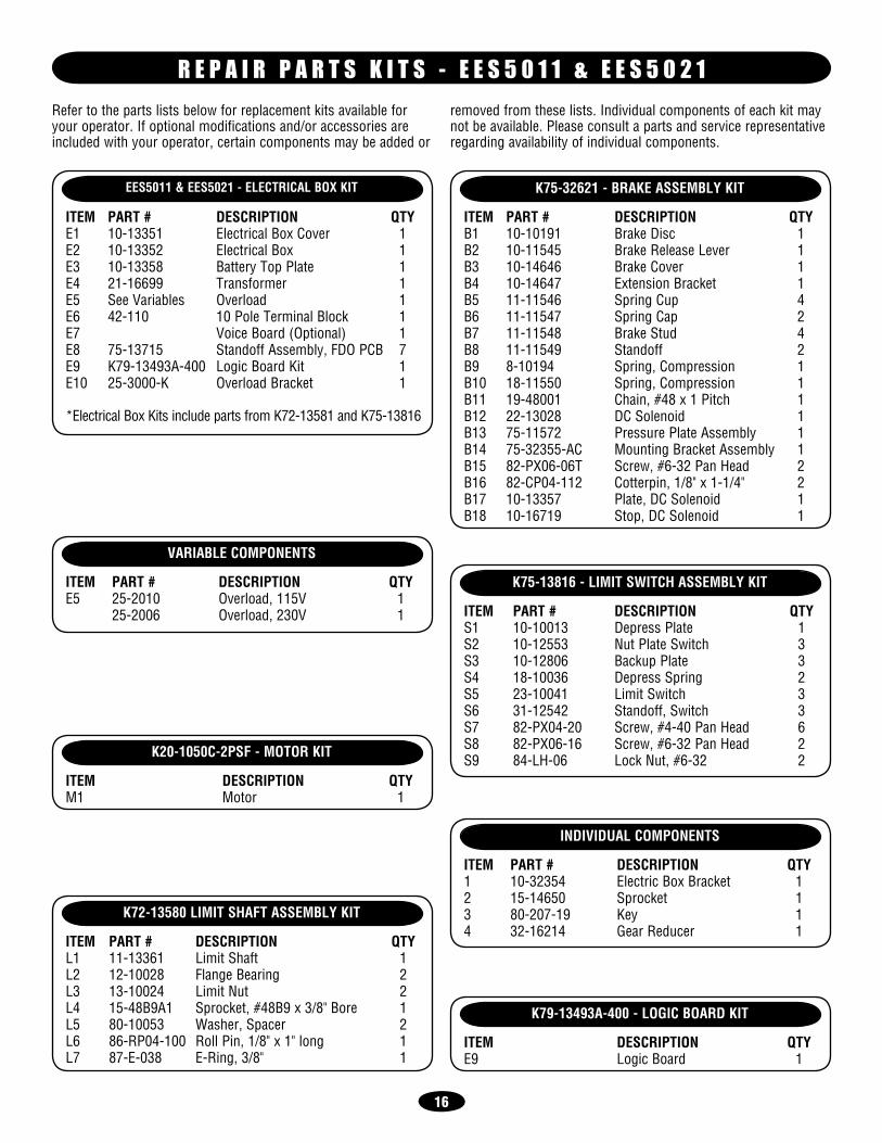
Refer to the parts lists below for replacement kits available for your operator. If optional modifications and/or accessories are included with your operator, certain components may be added or
removed from these lists. Individual components of each kit may not be available. Please consult a parts and service representative regarding availability of individual components.
EES5011 & EES5021 - ELECTRICAL BOX KIT
ITEM PART # DESCRIPTION QTYE1 10-13351 Electrical Box Cover 1E2 10-13352 Electrical Box 1E3 10-13358 Battery Top Plate 1E4 21-16699 Transformer 1E5 See Variables Overload 1E6 42-110 10 Pole Terminal Block 1E7 Voice Board (Optional) 1E8 75-13715 Standoff Assembly, FDO PCB 7E9 K79-13493A-400 Logic Board Kit 1E10 25-3000-K Overload Bracket 1
*Electrical Box Kits include parts from K72-13581 and K75-13816
VARIABLE COMPONENTS
ITEM PART # DESCRIPTION QTYE5 25-2010 Overload, 115V 1 25-2006 Overload, 230V 1
K72-13580 LIMIT SHAFT ASSEMBLY KIT
ITEM PART # DESCRIPTION QTYL1 11-13361 Limit Shaft 1L2 12-10028 Flange Bearing 2L3 13-10024 Limit Nut 2L4 15-48B9A1 Sprocket, #48B9 x 3/8" Bore 1L5 80-10053 Washer, Spacer 2L6 86-RP04-100 Roll Pin, 1/8" x 1" long 1L7 87-E-038 E-Ring, 3/8" 1
K20-1050C-2PSF - MOTOR KIT
ITEM DESCRIPTION QTYM1 Motor 1
K75-32621 - BRAKE ASSEMBLY KIT
ITEM PART # DESCRIPTION QTYB1 10-10191 Brake Disc 1B2 10-11545 Brake Release Lever 1B3 10-14646 Brake Cover 1B4 10-14647 Extension Bracket 1B5 11-11546 Spring Cup 4B6 11-11547 Spring Cap 2B7 11-11548 Brake Stud 4B8 11-11549 Standoff 2B9 8-10194 Spring, Compression 1B10 18-11550 Spring, Compression 1B11 19-48001 Chain, #48 x 1 Pitch 1B12 22-13028 DC Solenoid 1B13 75-11572 Pressure Plate Assembly 1B14 75-32355-AC Mounting Bracket Assembly 1B15 82-PX06-06T Screw, #6-32 Pan Head 2B16 82-CP04-112 Cotterpin, 1/8" x 1-1/4" 2B17 10-13357 Plate, DC Solenoid 1B18 10-16719 Stop, DC Solenoid 1
R E P A I R P A R T S K I T S - E E S 5 0 1 1 & E E S 5 0 2 1
K75-13816 - LIMIT SWITCH ASSEMBLY KIT
ITEM PART # DESCRIPTION QTYS1 10-10013 Depress Plate 1S2 10-12553 Nut Plate Switch 3S3 10-12806 Backup Plate 3S4 18-10036 Depress Spring 2S5 23-10041 Limit Switch 3S6 31-12542 Standoff, Switch 3S7 82-PX04-20 Screw, #4-40 Pan Head 6S8 82-PX06-16 Screw, #6-32 Pan Head 2S9 84-LH-06 Lock Nut, #6-32 2
K79-13493A-400 - LOGIC BOARD KIT
ITEM DESCRIPTION QTYE9 Logic Board 1
INDIVIDUAL COMPONENTS
ITEM PART # DESCRIPTION QTY1 10-32354 Electric Box Bracket 12 15-14650 Sprocket 13 80-207-19 Key 14 32-16214 Gear Reducer 1

17
6E
9E
3E
8E 3L
2L
2E
6L
4L
5L
9S
4S
4B
8S
1S
21B
71B
M11
4
41B3B
31B 51B
6B
9B1B
01B
61B
5B
7B
8B
2B
11B
7S81B
2S
4E
5L
7L
2L
5S
6S
3S
01E
5E
7E
1E
2
3
L3
L1
I L L U S T R A T E D P A R T S - E E S 5 0 1 1 & E E S 5 0 2 1

Refer to the parts lists below for replacement kits available for your operator. If optional modifications and/or accessories are included with your operator, certain components may be added or
removed from these lists. Individual components of each kit may not be available. Please consult a parts and service representative regarding availability of individual components.
EES1023 & EES1043 - ELECTRICAL BOX KIT
ITEM PART # DESCRIPTION QTYE1 10-13351 Electrical Box Cover 1E2 10-13352 Electrical Box 1E3 10-13358 Battery Top Plate 1E4 21-16698 Transformer 1E5 See Variables Overload 1E6 42-110 10 Pole Terminal Block 1E7 Voice Board (Optional) 1E8 75-13715 Standoff Assembly, FDO PCB 7E9 K79-13493A-400 Logic Board 1E10 25-3000-K Overload Bracket 1
*Electrical Box Kits include parts from K72-13581 and K75-13816
VARIABLE COMPONENTS
ITEM PART # DESCRIPTION QTYE5 25-4004-K Overload 3.3-5.5 Amp (230V 3 Ph) 1 25-4002-5K Overload 1.6-2.5 Amp (460V 3 Ph) 1
K72-13580 LIMIT SHAFT ASSEMBLY KIT
ITEM PART # DESCRIPTION QTYL1 11-13361 Limit Shaft 1L2 12-10028 Flange Bearing 2L3 13-10024 Limit Nut 2L4 15-48B9A1 Sprocket, #48B9 x 3/8" Bore 1L5 80-10053 Washer, Spacer 2L6 86-RP04-100 Roll Pin, 1/8" x 1" long 1L7 87-E-038 E-Ring, 3/8" 1
K75-13742 - MOTOR KIT
ITEM PART # DESCRIPTION QTYM1 07-10179-2 Brake Hub 1M2 20-3100C-4T Motor, 1 Hp 230/460V 3Ph, TEFC 1
K75-14998 & K75-15006 - BRAKE ASSEMBLY KIT
ITEM PART # DESCRIPTION QTYB1 10-10191 Brake Disc 1B2 10-11545 Brake Release Lever 1B3 10-14646 Brake Cover 1B4 10-14647 Solenoid Cover 1B5 11-11546 Spring Cup 4B6 11-11547 Spring Cap 2B7 11-11548 Brake Stud 4B8 11-11549 Standoff 2B9 18-10194 Spring, Compression 2B10 18-11550 Spring, Compression 4B11 19-48001 Chain, #48 x 1 Pitch 1B12 22- 13028 DC Solenoid 1B13 75-11572 Pressure Plate Assembly 1B14 75-14997 Mounting Bracket Assembly 1B15 82-PX06-06T Screw, #6-32 Pan Head 2B16 86-CP04-112 Cotterpin, 1/8" x 1-1/4" 2B17 10-13357 Plate, DC Solenoid 1B18 10-16719 Stop, DC Solenoid 1
R E P A I R P A R T S K I T S - E E S 1 0 2 3 & E E S 1 0 4 3
K75-13816 - LIMIT SWITCH ASSEMBLY KIT
ITEM PART # DESCRIPTION QTYS1 10-10013 Depress Plate 1S2 10-12553 Nut Plate Switch 3S3 10-12806 Backup Plate 3S4 18-10036 Depress Spring 2S5 23-10041 Limit Switch 3S6 31-12542 Standoff, Switch 3S7 82-PX04-20 Screw, #4-40 Pan Head 6S8 82-PX06-16 Screw, #6-32 Pan Head 2S9 84-LH-06 Lock Nut, #6-32 2
INDIVIDUAL COMPONENTS
ITEM PART # DESCRIPTION QTY1 10-35013 Electric Box Bracket 12 15-48B18QGH Sprocket 48B18 13 15-50B18QGH Sprocket 50B18 14 32-16234 Gear Reducer 1
K79-13493A-400 - LOGIC BOARD KIT
ITEM DESCRIPTION QTYE9 Logic Board 1
18

19
3
1
5
2
6E
9E
3E
8E 3L
2L
2E
6L
4L
5L
9S
4S
4B
8S
1S
21B
71B
M1
41B3B
31B 51B
6B
9B1B
01B
61B
5B
7B
8B
2B
11B
7S81B
2S
4E
5L
7L
2L
5S
6S
3S
01E
5E
7E
1E
2
L3
L1
6
1M
I L L U S T R A T E D P A R T S - E E S 1 0 2 3 & E E S 1 0 4 3
© 2009, The Chamberlain Group, Inc. 01-34990 All Rights Reserved
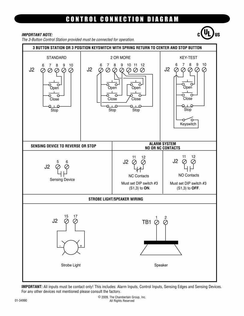
3 BUTTON STATION OR 3 POSITION KEYSWITCH WITH SPRING RETURN TO CENTER AND STOP BUTTON
KEY-TEST2 OR MORE
9 10 11 12
Stop
Close
Open
IMPORTANT NOTE:The 3-Button Control Station provided must be connected for operation.
IMPORTANT: All inputs must be contact only! This includes: Alarm Inputs, Control Inputs, Sensing Edges and Sensing Devices. For any other devices not mentioned please consult the factory.
Keyswitch
6 7 8
Stop
Close
Open
9 10
Stop
Close
Open
6 7 8
SENSING DEVICE TO REVERSE OR STOP
5 6
Sensing Device
11 12
NC Contacts
11 12
NO Contacts
ALARM SYSTEMNO OR NC CONTACTS
STROBE LIGHT/SPEAKER WIRING
15 17
Strobe Light
+-
1 2
Speaker
J2 J2
J2J2 J2
J2 TB1
Must set DIP switch #3(S1,3) to ON.
Must set DIP switch #3(S1,3) to OFF.
STANDARD
9 10
Stop
Close
Open
6 7 8J2
C O N T R O L C O N N E C T I O N D I A G R A M