Wavin PE Soil, Waste
60
Waste water drainage PRODUCT AND TECHNICAL MANUAL Wavin PE Soil, Waste and Vent applications
Transcript of Wavin PE Soil, Waste
Waste water drainagePRODUCT AND TECHNICAL MANUAL
Wavin PE Soil Wasteand Vent applications
2 PE Soil Waste and Vent applications Product amp Technical Manual Phone +31(0)38 42 94 951
Introduction page 4
1 WavinPESoilWasteandVentsystems page 5
11 Systemdescription page 5
12 Materialcharacteristics page 5
13 Applications page 6
14 Productspecifications page 6
2 Assembly page 8
21 General page 8
211 Pipeworkinthewasteremovalsystem page 8
212 Brackets page 8
213 Storage page 8
214 Ovalpipeends page 8
215 Shorteningpipes page 8
22 Jointing page 8
221 Principlesofheatfushing
polyethylenepipesandfittings page 8
222 Butt-welding page 9
223 Electrofusion page 12
3 Installation page 15
31 Installationusingflexionlegsexpansionbends page 15
32 Operationtreatmentandinstallationoflongpipecollars page 15
33 Rigidinstallationofopen-mountedPEpiping page 17
34 Securingusingfixingpoints page 17
35 Installationofexpansionjoints page 18
36 InstallationofWavinfireprotectionsleeves page 19
361 WavinBM-R90fireprotectionsleeve page 19
3611BM-R90Installationinstructions page 19
3612Components page 20
3613Typesofinstallation page 20
362 WavinBB-R90fireprotectiontape page 24
Contents
3 PE Soil Waste and Vent applications Product amp Technical Manual
37 WavinPEAirmixSoventfitting page 26
371 Introduction page 26
372 Benefits page 26
373 Applications page 26
38 Castinginheatcuredconcreteandextrusionshrinkage page 26
39 Cast-inpipework page 27
391 Layingofsewagepipes page 27
392 Inspectionshafts page 29
4 Situationsduringconstruction page 28
5 Pressuretesting page 28
6 Maintenance page 29
7 Chemicalresistance page 30
8 Packagingtransportandstorage page 34
81 Packaging page 34
82 Transport page 34
83 Pipestorage page 34
84 Storingmouldedparts page 34
9 Productlist page 35
4 PE Soil Waste and Vent applications Product amp Technical Manual Phone +31(0)38 42 94 951
WavinPEProductampTechnicalGuide
This technical manual on PE above-ground drainage systems
deals with the removal of domestic waste water and rainwater
from houses and residential and commercial properties using
plastic piping systems
It covers all aspects from design to installation The manual is
intended for clients architects construction specialists building
co-operatives building inspectors and of course for instal-
lers If you have any questions wishes or practical problems
not covered by this manual then we would ask you to submit
them to us together with any suggestions for amendments
and additions
Since our systems are often utilised in circumstances beyond
our control we cannot accept liability for the consequences of
applying the information provided in this manual This edition
of the manual supersedes all previously published technical
data
Introduction
5 PE Soil Waste and Vent applications Product amp Technical Manual
11Systemdescription
Wavin PE is a universal system approved for pipe installation
in buildings to DIN 19535 and DIN EN 1519 and for under-
ground pipes to DIN EN 12666 The product range includes
pipes and fittings with dimensions between 40 and 315 mm
Wavin PE is a complete soil waste and vent system of pipes
and fittings manufactured from high-density polyethylene
(PE HD) This tough and durable PE system offers an extra-
ordinary chemical resistance in combination with a high flexi-
bility level and great impact resistance Wavin PE pipes and
fittings are jointed by welding making the joints resistant to
tension There are two methods of welding butt welding and
electro-fusion welding Most Wavin PE products can also be
used as part of under-pressure installations like the siphonic
roof drainage system Wavin QuickStream
12Materialcharacteristics
High-temperature resistance
Wavin PE guarantees resistance to
temperatures of up to 100degC and is suitable
for washing-machine and dishwasher
drainpipes
Flexibility
Wavin PE is well suited to assemblies
subjected to vibration It is therefore ideal
for use in seismic zones and across
expansion joints
UV resistance
With the addition of a percentage of carbon
black PE is UV-stabilised and can therefore
be installed outdoors without degradation
problems
Ease of welding
An advantage of Wavin PE is that it can
be welded (both by butt welding and with
electrofusion joints) thereby providing a
perfectly sealed system
Low weight
Wavin PErsquos lightness makes transportation
and handling easy
Use of adhesives
Because of its high resistance to chemical
agents Wavin PE cannot be jointed with
adhesives
Low-temperature resistance
The elasticity of Wavin PE allows pipes to
withstand freezing of internal water
Impact resistance
Wavin PErsquos elasticity gives pipes a high
impact strength at temperatures as low as
-40degC This ruggedness makes handling of
pipes easy during installation
Blockage-free
The smooth surface of Wavin PE allows for
both an optimum flow of any type of waste
material and self-cleaning of pipes
Fire Hazards
Wavin PE does not issue any toxic gases
during combustion
Wavin PE connection seals
Quick-fit coupling and expansion joint seals
remain resistant to all chemical agents
even if only slightly wetted by waste water
The seals are produced from an elastomer
which guarantees sealing and durability
even in extreme conditions
1 Wavin PE Soil Waste and Vent system
6 PE Soil Waste and Vent applications Product amp Technical Manual Phone +31(0)38 42 94 951
13Applications
Domestic waste-water system
Tensile resistant joint technology guarantees the highest
levels of leakage security The Wavin PE waste-water piping
system complies with DIN 19535 and DIN EN 1519 and is
resistant to the effects of hot water It meets the requirements
of DIN EN 12056 and DIN 1986 -100 (95deg short-term loading)
Rainwater piping
Wavin PE waste-water piping is suitable for use on rainwater
drainage systems PE piping can be used in low-pressure
systems to drain free surface waters and rainwater (see the
Wavin QuickStream technical handbook)
Underground piping
The options for using PE piping systems for underground drai-
nage are outlined in DIN 12666 -12005 This standard defines
parameters such as pipe diameter wall thickness and rigidity
Minimum ring stiffness standards of SN 4 (4 KNm2) are
required for all ldquoUldquo-category applications (external under-
ground piping) The Wavin PE (110 ndash 315 mm) waste-water
system complies with the SN 4 (4 KNm2) ring stiffness spe-
cifications Pipe range lt SDR 26 (eg SDR 33SN2) is not
suitable for underground applications Data on SDR and ring
stiffness specifications can be found in the pipe data table
Industrial waste-water
The Wavin PE system is resistant to aggressive chemicals
Further details about the chemical resistance of PE-HD can
be found in chapter 7 on page 31 and in the Wavin ldquoChemical
Resistancerdquo data sheet
Pumping systems
PE waste-water systems are primarily used on non-pressu-
rised applications However they can also be used without
hesitation on systems subject to short-term pressure loading
(ie pumping systems) They are capable of handling maxi-
mum internal pressures of 15 bar Installation and fixing must
be carried out in accordance with the given specifications
Manufacture and testing
Wavin PE piping complies with the technical specifications in
DIN EN 1519 and DIN 19535 Part 2 as tested by the National
Materials Testing Facility
14Productspecifications
Basic material
Wavin PE waste-water pipes and fittings are manufactured
from PE - HD material
Colour
Black
Identification and labelling
Wavin PE nominal diameters year of manufacture material
supervision marks fire category B2
Example Wavin PE EN 1519 IIP 152 UNI Ue DIN 19535 DN
100 110 x 43 PE BD S 125 weldable tempered A-M-G-T
Properties
Melt flow index 03 ndash 089 g10 min
Coefficient of expansion 02 mmm degC
UV resistance given by carbon content
of 2 ndash 25
Fire behaviour DIN 4102 B2
7 PE Soil Waste and Vent applications Product amp Technical Manual
Quality assurance
All piping and fittings are subject to continuous internal quality
control procedures The system is also subject to external
monitoring by the Materials Testing Facility The system
conforms to the established technical specifications set out
in Building Regulations A Part 1 Issue 20031 No1218 and
comply with
DIN EN 1519 - 12001-01 and
DIN 19535 - 10200-01
Information on the transportation and
storage of PE pipes and fittings
PE pipes must be protected against damage during trans-
portation and especially during loading and unloading Prior
to any unloading pipes should be carefully inspected for
damage incurred during transportation Where lifting gear is
to be employed the use of wide belts and slings is recom-
mended Unpaletted pipes should wherever possible be
supported along their entire length and prevented from rolling
against each other Pipe storage areas and supporting surfa-
ces should be free from sharp edges
Caution
Short-term pipe deformation can occur where pipes are
unevenly exposed to the effects of the sun (or other forms
of heat) Pipes should therefore not be stored in direct
sunlight
d
s
di
SDR = dis
Pipe data
Calculating SDR category
DN d1 di2 s3 SDR4 SN
mm mm mm
40 40 340 30 136 -
50 50 440 30 17 -
56 56 500 30 17 -
60 63 570 30 21 -
70 75 690 30 26 -
90 90 830 35 26 4
100 110 1014 43 26 4
125 125 1152 49 26 4
150 160 1476 62 26 4
200 200 1876 62 33 2
200 200 1846 77 26 4
250 250 2344 78 33 2
250 250 2308 96 26 4
300 315 2954 98 33 2
300 315 2908 121 26 4
1) external diameter in mm
2) internal diameter in mm
3) wall thickness in mm
4) SDR category
5) Max pressure in mbar
Table 1
8 PE Soil Waste and Vent applications Product amp Technical Manual Phone +31(0)38 42 94 951
As well as the design of the installation there is also the actual
assembly The design is complete but many decisions remain
to be taken by the fitter which will impact on the quality of the
work and the problem-free operation of the waste removal
system
21General
211Pipeworkinthewasteremovalsystem
The pipework must be installed with a particular fall as indi-
cated on the drawings using brackets bands and supports
They must not be fitted horizontally but there must not be
too great a fall Excessive fall leads to the complete closure
of the pipe and to poor ventilation Where reducing pieces are
used the top of the pipework should be at the same level The
desired installation method must be known
212Brackets
All types can be used with support brackets from light nylon
band brackets light or heavy PVC brackets to galvanised
sewer brackets and suspension bands Ensure that any
sliding brackets do actually slide (avoid over-tightening)
Brackets used for clamping must be strong For fixed point
brackets (only with PE) galvanised steel brackets must be
used
213Storage
Rubber O-rings must be kept in a cool and dark place and not
exposed to sunlight (not even behind glass) Pipes must be
stored as flat as possible to prevent sagging It is difficult to
produce neat straight work with bent pipes Keep pipes as
clean as possible this saves time when preparing and making
connections Covering is recommended during extended
storage outdoors Ensure that PE pipes and particularly the
ends do not take on an oval shape Oval pipes create extra
work when welding joints Bear in mind that pipes can get
very hot in the sun Once out of the sun they will shrink again
If the pipe is at 70degC and the temperature inside is 20degC a 5
metre long PE pipe will be 02 x 50 x 5 = 50 mm shorter Leave
accessories in the packaging as long as possible PE electro-
weld sleeves should be stored indoors and left as long as
possible in the packaging to prevent oxidation from sunlight
Oxidation on the interior can badly affect welds
214Ovalpipeends
Excessively oval shape PE pipe ends should first be made
rounder This can be done by clamping the pipe with one or
two brackets with one or two pieces of padding between
placed a little back from the eventual coupling insertion depth
at the end of the pipe The brackets are only removed after
the weld has cooled
215Shorteningofpipes
The best and simplest method is to use a proper pipe cutter
The cut is then straight and no burrs are generally created If
a saw is used care needs to be taken to ensure that the cut
is straight mark the cut use a stiff saw blade and use a saw
horse with Oslash above 50 mm Remove internal and external
burrs with steel wool or a knife For sawing PE use a fairly
coarse-toothed blade with a wide set
22Jointing
Joints fall in principle into two categories those resistant
to tension and those not resistant to tension Welded and
flanged joints are resistant to tension Expansion sockets and
connections using rubber seals are not resistant to tension
PE pipes can not be joined using solvent cement as PVC can
However welding of PE gives excellent results This creates
a tension-resistant connection There are two methods of
welding butt welding and electro-welding using fittings with
integral heating elements
221Principlesofheatfusingpolyethylenepipesand
fittings
The Wavin PE range contains pipes spigot fittings and elec-
trofusion sockets Pipes and fittings (both electro fusion cou-
plers and spigot fittings) are provided with external marking
ribs or marking stripes enabling easy alignment particularly in
pre-fabrication Note polyethylene pipes and fittings cannot
be joined using solvent cement
For correct heat fusion of polyethylene following basic equi-
rements must be met in order to obtain good quality joints
1 Sufficient heat
2 Sufficient pressure
3 Sufficient welding amp cooling time
4 ldquoClean to cleanrdquo material
Assembly
9 PE Soil Waste and Vent applications Product amp Technical Manual
In the two most common applied welding techniques elec-
trofusion and butt-welding these parameters are dependent
on the design of the electrofusion socket andor in the wel-
ding procedure
222Butt-welding
Butt-welding is a very economical jointing technique
Correctly made butt-welds reach the strength of the pipe
Well-trained personnel are recommended for making butt-
welds
In butt welding two pipe ends two fitting ends or a pipe
end and a fitting end are bonded by melting the circu-
lar pipe faces simultaneous and pressing these together
Butt-welding can only be performed using a butt-welding
machine
The butt-welding procedure
incorporates the following 15 steps
1 Check environmental conditions
When the outside temperature is below 5 ordmC andor
during rainy and windy conditions special precautionary
measure have to be taken to ensure dry and sufficiently
warm welding conditions
2 Check welding machine is in good functional order
At least the following issues should be checked
temperature alignment play of the moving parts smooth
movement of the moving parts electrical connections
cutting machining plane (sharpness)
3 Clean heater plate with PE cleaner and a soft cloth
Prevent any damage of the Teflon coating
4 Check temperature heater plate on 210 ordmC
5 Cut pipe to required length
Note take into account that in the welding process a few
millimetres pipe will be consumed Best practice is to use
a rotary pipe cutter The pipe ends are then square and
free from burrs If a saw is used it is advised to use a
spare clamp as a sawing guide Such cut pipe ends must
be de-burred before placing in the welding machine
Figure 1
Figure 2
Figure 3
10 PE Soil Waste and Vent applications Product amp Technical Manual Phone +31(0)38 42 94 951
6 Clamp both pipe-ends in the welding machine
and ensure correct alignment
Eliminate any bending forces if present
7 Trim both pipe-ends using the planer
Keep planer running while slowly reducing pressure
Do not stop planer when still in contact with pipe ends
in order to prevent uneven surfaces
8 Check that pipe ends are matching
If not correct either re-clamp pipes (alignment) andor
repeat trimming After re-clamping it is necessary to trim
the pipe-end again with a planer
9 Insert heater plate and press both pipe ends during
a few seconds with a higher force on the plate for
ensuring full contact
Figure 4
Figure 5
Figure 7
Figure 8Figure 6
11 PE Soil Waste and Vent applications Product amp Technical Manual
10 Reduce force until nearly zero assuring contact with
heater plate so that heat is soaked into both pipe ends
11 Maintain heat soaking till a bead is formed of
approximate 1 mm for diameters 40 up to 200
and 15 mm for diameters 250 and 315 mm
Use the figures mentioned in table 2 as guidance for the
heat soaking duration
12 After heating time is elapsed quickly open the
welding machine remove the heater plate and close
immediately
This part of the welding operation must be kept as short
as possible in order not to loose too much heat
15 Remove welded joint from the welding machine after
cooling time is elapsed
The joint need to be kept free from any loads within
5 minutes after the cooling time is elepsed
If the above steps are followed correctly the above
mentioned four basic requirements should be fully met
13 Slowly apply welding force and maintain for required
cooling time according to table 2a
14 Inspect weld bead for evenness
Uneven weld beads indicate incorrect alignment or out
of roundness Large weld beads could be caused by
either too high a heater temperature andor too high a
welding force A small weld bead could be caused by a
too low a heater temperature andor too low a welding
force In both cases the weld should be rejected due to
reduced strength
Figure 9 Figure 10
Diameter 40 50-110 125 160 200 250 315
Time [s] 30 40 60 80 100 140 170
Diameter 40-75 90 110 125 160 200 250 315
Time [s] 60 70 80 100 120 200 280 340
Table 2 Guidance of the heat soaking duration (in seconds) for
butt-welding
Table 2a Guidance of the minimum cooling time (in seconds)
for butt-welding at 20ordm C
12 PE Soil Waste and Vent applications Product amp Technical Manual Phone +31(0)38 42 94 951
223Electrofusion
Electro fusion couplers are fitted with a resistance wire Heat
should be applied to the welding zones using appropriate
welding equipment (see Pages 58 and 59) The polyethylene
expands during the fusion process This expansion ensures
that the necessary welding pressure is generated Wavin
welding equipment automatically supplies the precise amount
of heat required for a perfect weld One type of electro weld
equipment is available (see product range)
InstallationRequiredtools
Pipe cutter
Circumferential measuring tape
Rotary peeler or hand scraper
PE cleaner
Lint-free colorless and clean cloth
Measuring stick
Permanent marker
230VAC power supply
Welding machine suitable for WAVIDUO
couplers (DUO 315)
Pipe clamp if appropriate
NOTICE-Faultypipeconnection
Insufficient preparation and non-observance of the installation
instructions may lead to a faulty pipe connection The functio-
ning and life-time of the system and the connection may be
affected Please adhere to the instructions in this installation
manual and the operating instructions provided with the wel-
ding machine
The pipe ends must be cut precisely The pipe ends should
be fully inserted until the marked position on the pipes Failing
to adhere to the welding instructions can lead to overheating
of the pipe connection during the welding process and in
extreme cases lead to a fire hazard
NB Never weld a WAVIDUO electro fusion coupler twice
A faulty connection must be cut out and be replaced by a
new coupler
General
With wet and cold conditions on site take special precautions
in order to create a working environment that is sufficiently
dry and warm
When installing the system the maximum acceptable
temperature range is -10degC to +40degC
Electro fusion couplers weld time (approx)
Note the data given in the following table is approximated
since weld times are dependent on ambient tempera-
ture and are a function of the welding equipment used
The data given in the table is relevant to ambient tem-
peratures of 23 degC and 230 V supply
Equipment type weld zone Electro fusion couplers
for use in jointing
WaviDuo 40 ndash 315 WaviDuo couplers
Machine
Type No 4700200
plus compatible couplers up to 160 mm
Overview electro fusion machines and couplers
WaviDuo electro fusion coupler
Dimension Weldingtime (ca)
mm s
40 ndash 160 82
200 - 315 370
Using electroweld equipment
Always read the manufacturerrsquos operating instructions and the
contents of DVS 2207 before using pipe collar welding equi-
pment Where no operating instructions are available please
contact Wavin Overseas
13 PE Soil Waste and Vent applications Product amp Technical Manual
Electro fusion jointing procedure
1) Clean pipe roughly in the circumferential direction cut
precisely square with pipe cutter and deburr edges
Cut off obvious reversed pipe ends
2) Check fusion ends with a circumferential measuring tape
before and after peeling operation Adhere to standards
and specifications (EN 12666-1) (See Table 3)
3) Measure the length of the coupler with a measuring stick
to calculate the peeling length Formula for peeling
length (coupler length 2) + 10mm In case of use as
a sliding coupler or repair coupler the peeling length is
equal to the length of the coupler Remove center stop
with a knife
4) Measure area which must be peeled with a measuring
stick on the pipe and mark with a permanent marker
Step 3
Step 7
Step 9
Step 5
Step 4
Step 8
Step 11
Step 6
5) Peel pipe with a rotary peeler or hand scraper past the
marking Do not use sand paper Ensure that the com-
plete surface of the peeling area is peeled sufficiently
Minimum peeling thickness of 02 mm (See Table 3)
6) Clean the peeled area of the pipe with PE cleaner using
a clean lint-free colorless cloth in circumferential
direction and let the cleaner evaporate
7) Always mark the insertion depth with a permanent
marker on the pipe Formula for insertion depth (coupler
length 2) See NOTICE Faulty pipe connection (page
12)
8) Clean the inside of the electro fusion coupler with PE
cleaner using a clean lint-free colorless cloth in circum-
ferential direction and let the cleaner evaporate until
coupler is free of residues
9) Proper marking allows complete control over fully
inserting the pipe and movements of pipe and fittings
during the welding process See NOTICE Faulty pipe
connection (page 12)
10) Ensure a low stress installation Secure pipe and electro
fusion coupler against movements If appropriate use
pipe clamps to hold the system in place
11) Follow the instructions on the display of the welding
machine Control and supervise fusion process
Do not touch the electro fusion coupler during the fusion
process and the cooling time Risk to be burned
14 PE Soil Waste and Vent applications Product amp Technical Manual Phone +31(0)38 42 94 951
Pressure testing pipe systems
There are no standard requirements relating to rainwater
piping in buildings Where a pressure test is to be carried
out close off the piping system at the cleaning trap using a
sealing bladder The system can then be filled with water
and the pressure value above hydrostatic determined
Step 12 Before
Table 3
Step 12 After
12) During and after fusion check message on display of
the fusion unit When fusion is successful remove fusion
cables Check fusion indicators on the coupler Both
indicators have to be visible If not coupler must be cut
out and a new coupler should be installed Defective
connections must not be welded twice See NOTICE
Faulty pipe connection (page 12)
13) Make sure you have a low stress installation Secure the
pipe and electro fusion coupler against movements (ie
using pipe clamps) and keep fixed and still until cooling
time has elapsed
Diameter Oslash d40 d50 d56 d63 d75 d90 d110 d125 d160 d200 d250 d315
Min pipe Oslash [mm] 396 496 556 626 746 896 1096 1246 1596 1996 2496 3146
Cooling Time [min] 10 10 10 10 15 15 15 15 15 20 20 20
Minimum wall reduction by peeling 02 mm
15 PE Soil Waste and Vent applications Product amp Technical Manual
Due to the elastic modulus of polyethylene any temperature-
related changes in length can be absorbed using flexion legs
Flexion leg length (BS) is given by
the change in length (DL) of the expansion leg (DS)
PE piping external diameter
Temperature-related changes in PE pipe length (DL) are
transferred to the flexion legs by the guide clamp fixing
points (FP)
The following parameters are used to determine flexion leg
length in the diagram below (Fig 73)
Average coefficient of linear expansion
of PE - HD = 02 mmm degC
flexion leg radicde x ∆L
de = external diameter
L = change in length
32Operationtreatmentandinstallation
ofexpansionsockets
Expansion sockets are used for taking up expansion on appli-
cations where flexion legs cannot be installed
Long collars should be fixed rigidly to the supporting struc-
ture The fixtures (clamps) must be capable of withstanding
the forces applied during pipe installation and subsequent
sliding movements The forces applied during pipe installation
are those generated when pushing home the tapered pipe
ends The sliding resistance is the ability of the long pipe col-
lar to withstand the effects of temperature-related changes in
the length of the pipe
Flexion leg length in mm
Temperature difference in degC
L = change in length in mm
R = pipe length in mm
DS = expansion leg
BS = flexion leg
DL = expansion length
FP = fixing point
FS = guide clamp
Flexion leg length (mm) Temperature difference (degC)
∆L
= le
ngth
cha
nge
(mm
)
R =
pip
e le
ngth
(mm
)
external diameter (mm)
Figure 11 Installation using flexion legs
Figure 12 Calculation of flexion leg length
Table 4 Installation force and sliding resistance
31Installationusingflexionlegsexpansionbends
Dimensions Installation sliding resistance
forces under operating conditions
De N N
50 - 63 200 100
75 250 120
90 300 200
110 400 300
125 550 400
160 800 700
200 1200 1000
250 1800 1500
315 2600 2200
Installation
16 PE Soil Waste and Vent applications Product amp Technical Manual Phone +31(0)38 42 94 951
Pipe ends should be evenly chamfered to an angle of approxi-
mately 15deg Use lubricant on the spigot end as this allows the
pipe end to be inserted with minimum resistance
Expansion socket is designed to support a maximum pipe
length of 6 m The appropriate number of long pipe collars
must therefore be calculated when supporting longer pipe
runs Mark off the required insertion depths champfer the
male pipe ends and use lubricant
The insertion lengths required are dependent on the tem-
perature of the surroundings during installation Installation
temperatures of 20 degC require insertion lengths of 105 cm
installation temperatures of 0 degC require only 8 cm insertion
lengths
Figure 13
Chamfering in
pipe ends
Figure 14
Fixing a long pipe collar
Figure 15 I nsertion length as a function of
installation temperature
Table 5 Threaded pipe (fittings) as a function of
wall and ceiling gap
Wall or
ceiling gap d d d d d d d
L (mm) 50 - 90 110 125 160 200 250 315
100 frac12rdquo frac12rdquo frac12rdquo - - - -
150 frac12rdquo frac12rdquo frac12rdquo frac12rdquo - - -
200 frac12rdquo frac12rdquo frac12rdquo frac12rdquo frac34rdquo 1rdquo -
250 frac12rdquo frac12rdquo frac12rdquo frac34rdquo 1rdquo 1rdquo 54rdquo
300 frac12rdquo frac12rdquo frac12rdquo frac34rdquo 1rdquo 54rdquo 54rdquo
350 frac12rdquo frac12rdquo frac12rdquo 1rdquo 1rdquo 54rdquo 1 frac12rdquo
400 frac12rdquo frac12rdquo frac34rdquo 1rdquo 1rdquo 54rdquo 1 frac12rdquo
450 frac12rdquo frac12rdquo frac34rdquo 1rdquo 54rdquo 54rdquo 1 frac12rdquo
500 frac12rdquo frac34rdquo frac34rdquo 1rdquo 54rdquo 1 frac12rdquo 2rdquo
550 frac12rdquo frac34rdquo frac34rdquo 1rdquo 54rdquo 1 frac12rdquo 2rdquo
600 frac12rdquo frac34rdquo 1rdquo 1rdquo 54rdquo 1 frac12rdquo 2rdquo
Installation Fixation
The ceiling plates and pipe clamps to be used will dependent
on the size of the wall or ceiling gap L and the pipe diameter
Choose the appropriate ceiling plate or disc to match the
gap L
The section modulus W should be calculated where the
value of L is large The following formula can be used
W = L bull Ks
W = section modulus in cm3
L = Wall or ceiling gap (cm)
K = Sliding resistance (kp) in Newtons (N) ndash see table below
s = allowable bending stress of the fixture in kgcm2
(2000 kgcm2)
Fixing pointGuide length
17 PE Soil Waste and Vent applications Product amp Technical Manual
33Rigidinstallationofopen-mounted
PEpiping
Wall- or ceiling-mounted piping should be installed under the
following rigid fixing point (FP) conditions
The fixtures (fixing points) must be capable of withstanding
the often substantial forces generated by pipe expansion and
contraction
34Securingusingfixedpoints
The fixed points are used for rigid installation must be
capable of withstanding much greater expansion forces than
those occurring in the case of installations where expansion
sockets or expansion legs and elbows are used Pipes with
diameters of up to 160 mm can be secured using clamps with
G 12rdquo threaded collars with fittings and mating pipes to G 2rdquo
(see Table 6) Reduction collars can be used to achieve the
required diameters
The rawlplugs used must be capable of withstanding the
actual weight of the loaded piping and the resulting tensile
forces generated by expansion
Table 6 Sliding resistance in N
Table 7 Threaded pipe (fittings) as a function of wall
and ceiling gap
Table 8 Actual weight of the loaded piping
Figure 16 Examples of anchor point attachment
Dimension ring surface assumed temperature difference
ca +20deg C ndash +90degC ca +20deg C ndash -20deg C
Sliding resistance Sliding resistance
d cm2 N N
56 50 1250 3150
63 56 1288 2528
75 68 1700 4280
90 95 2375 5985
110 140 3500 8820
125 185 4600 11650
160 296 7400 18650
200 377 9400 23750
250 595 14900 37500
315 939 23500 59150
Wall orceiling gap d d d d dL (mm) 50 - 56 63 - 75 110 125 160100 frac12rdquo frac34rdquo 1rdquo 1rdquo 1 frac14rdquo150 frac34rdquo 1rdquo 1rdquo 1 frac14rdquo 1 frac14rdquo200 frac34rdquo 1rdquo 1 frac14rdquo 1 frac12rdquo 1 frac12rdquo250 1rdquo 1rdquo 1 frac14rdquo 1 frac12rdquo 2rdquo300 1rdquo 1 frac14rdquo 1 frac14rdquo 2rdquo 2rdquo350 1 frac14rdquo 1 frac14rdquo 1 frac12rdquo 2rdquo 2rdquo400 1 frac14rdquo 1 frac14rdquo 1 frac12rdquo 2rdquo -450 1 frac14rdquo 1 frac12rdquo 2rdquo 2rdquo -500 1 frac14rdquo 1 frac12rdquo 2rdquo - -550 1 frac14rdquo 1 frac12rdquo 2rdquo - -600 1 frac12rdquo 1 frac12rdquo 2rdquo - -
de kg weight mm m Nm50 1940 1656 2440 2063 3080 2675 3380 3890 6388 55110 9500 100125 12290 120160 20150 200200 31240 310250 48820 490315 77500 780
Example Given value de = 110 mm RA = 15 m (pipe clamp interval) Required value actual weight over section RA Formula G = Nm x RA
100 Nm (table left) x 15 m = 150N
L = ceiling gap bull X = hole distance bull P = expansion force (see Table 1) G = actual weight of loaded piping bull Z = tensile force on screws de = dimension bull RA = pipe clamp interval
18 PE Soil Waste and Vent applications Product amp Technical Manual Phone +31(0)38 42 94 951
35Installationofexpansionjoints
Expansion joints are push-fit sockets with a rubber seal
Expansion and contraction in the pipe system is absorbed
by axial displacements in the sockets Normally expansion
joints are mostly located in the vertical downpipes In special
circumstances if no other options remain to absorb ther-
mally induced displacements expansion joints can be posi-
tioned in horizontal collector pipes
Figure 17 Installation of an expansion joint
Figure 18
Table 9 Insertion depth of pipes into an expansion socket max pipe length 6 meter
Pipe diameter
le 50 63 75 90 110 125 160 200 250 315Ambient temperature Insertion depth in [mm] for pipe length of 6 meter
- 10deg C 65 70 70 80 85 90 100 140 140 140
0deg C 75 80 80 90 95 100 110 150 150 150
+ 10deg C 85 90 90 100 105 110 120 160 160 160
+ 20deg C 95 100 100 110 115 120 130 170 170 170
+ 30deg C 105 110 110 120 125 130 140 180 180 180
2 Chamfer pipe end
Chamfer angle should be approximately 15deg and
chamfering length should be minimum 4 mm
For a good functioning of the expansion joints follow these
instructions
1 Prepare positions of fix- and sliding brackets
Expansion sockets must always be configured as a fixed-
point That means that all other fixing points must be
sliding brackets (see figure 87)
3 Mark insertion depth
Use the insertion depth for the ambient temperature during
installation according to the values mentioned in table 9
19 PE Soil Waste and Vent applications Product amp Technical Manual
Figure 19
4 Install pipe and fix with a fixed-point bracket on the
socket side and sliding brackets over the rest of the
pipe length
5 Check depth of insertion
Figure 20
36InstallationofWavinfire
protectionsleeves
361WavinBM-R90fireprotectionsleeve
Wavin BM-R90 is a new fire-protection sleeve designed for
use with Wavin domestic waste water removal piping
systems according to DIN 4102-11 It is suitable for use on
piping with external diameters of up to 160 mm and is able
to provide a secure seal for use in all conceivable installation
situations
Right-angled wall and ceiling penetration
Lightly-constructed partition walls
Angled wall and ceiling penetration to 45˚
For sealing over pipe collars (to 45˚)
For installation under ceilings and in front of walls
Installation flush with ceiling surface
3611BM-R90Installationinstructions
The BM-R90 fire collar provides fire resistant sealing for wall
and ceiling installation of the Wavin PE Soil amp Waste system
The BM-R90 fire collar is approved by the German Institute
Building (DIBt) approval no Z-1917-1924
General recommendations
1) Positioning of the collars on both sides of a wall on one
side under in a ceiling (see Fig 25)
2) Wall amp ceiling types at least 10 cm thick solid concrete
aerated concrete and sand-lime brick walls as well as
light dividing walls (stud walls both sides clad with 125
mm plasterboard) and solid concrete and aerated
concrete ceilings at least 15 cm thick
3) Structural acoustic insulation the acoustic insulation mat
provided must be wrapped around the pipe where it
passes through the wall or ceiling
4) Joint sealing between pipe and wall ceiling to be
packed to the full thickness of the wall or ceiling using
mineral materials such as concrete cement or plaster
20 PE Soil Waste and Vent applications Product amp Technical Manual Phone +31(0)38 42 94 951
Acoustic insulation mat
Gap around the egdeBM-R90 collar
150
mm
150
mm
BM-R90 collar
Gap around the edge
Acoustic insulation mat
Acoustic insulation mat
BM-R90 collar
150
mm
Gap around the edge
Figure 21 BM-R90 fire collar
Table 10 BM-R90 selection table for
various types of Wavin PE pipe
installation
1) The shape of the sleeve must be
turned oval by pushing on both
sides In that way the shape of
the sleeve can be adapted when
leading-through the pipes
(see also Figure left)
Figure 22 Straight installation without
sleeve socket up to 160 mm
3612Components
The fire collars are made from powder coated sheet steel
with a push-in fastening and tab fixings with an integrated
intumescent material for reliable closure in the event of fire
Also included
insulation mat
fixing kit
identification label
declaration of conformity (Enclosure 1)
Selection table
3613Typesofinstallation
I) Ceiling installation
Minimum requirements of the ceiling
min 150 mm thick concrete ceiling
Flush ceiling installation
Wrap insulating mat around the pipe
Open the collar and position it around the pipe whilst
hooking in the push-in fastening Bend or angle the collar
mounting tabs Then install the collar flush with the ceiling
Fill the remaining ceiling gap with cement or concrete (see
general recommendations (4)
Wavin PE pipes d s Straight Straight Angled
mm mm Installation installation installation 1)
mm with sleeve With sleeve or
socket le 45deg
40 40 30 40 63 7550 50 30 50 63 7556 56 30 63 75 9070 75 30 75 90 11090 90 35 90 110 125100 110 43 110 125 140125 115 49 125 140 160150 160 62 160 180 200200 200 6277 200 - -
II) Installation under the ceiling
Straight ceiling installation
Wrap insulating mat around the pipe Open the collar and
position it around the pipe whilst hooking in the push-in
fastening Fill the remaining gap with cement or concrete
(see general recommendations (4)) Hold the collar firmly
against the ceiling and mark the positions of the mounting
holes
Rotate the collar and drill the holes
Insert plugs and fix the collar using screws and washers
(Mounting the collar using the washers plugs and screws
provided)
21 PE Soil Waste and Vent applications Product amp Technical Manual
Angled ceiling installation
Wrap insulating mat around the pipe
Open the collar and position it around the pipe whilst
hooking in the push-in fastening Fill the remaining gap with
cement or concrete (see general recommendations (4)
Hold the collar firmly against the ceiling and mark the
positions of the mounting holes
Rotate the collar and drill the holes
Insert plugs and fix the collar using screws and washers
(Mounting the collar using the washers plugs and screws
provided)
Installation distances between BM-R90
fire protection collars eg to external systems
The distance to external tested systems (inspected and
approved) must be at least 50 mm between partitioned
sections
If two Wavin R90 feedthroughs are installed next to each
other the distance between the pipes must be at least 100
mm in the case of special partitioned sections (sloping
pipes partition via sleevesocket or for ceiling installations)
In the case of straight pipes without sleevesocket in the
partition area the collar casings can adjoin each other
(distance 0 mm)
III) Wall installation
Minimum wall specifications wall must be at least 100 mm
thick made from concrete aerated concrete l ime
sandstone or lightweight partition walls (two-layer panelling
on both sides with 125 mm plasterboard panels and mineral
wool infill) The pipe must be clamped on both sides at a
distance of le 50 cm For wall feedthroughs a collar should
always be fitted on both sides of the wall
Wrap insulating mat around the pipe Open the collar and
position it around the pipe whilst hooking in the push-in
fastening Fill the remaining gap with cement or concrete
(see general recommendations (4) Hold the collar firmly
against the ceiling and mark the positions of the mounting
holes
Rotate the collar and drill holes
Insert plugs and fix the collar using screws and washers
(Mounting the collar using the washers plugs and screws
provided)
Repeat the steps described for the second collar required
on the opposite side
Acoustic insulation mat
Gap around the egdeBM-R90 collar
150
mm
150
mm
BM-R90 collar
Gap around the edge
Acoustic insulation mat
Acoustic insulation mat
BM-R90 collar
150
mm
Gap around the edge
Acoustic insulation mat
Gap around the egdeBM-R90 collar
150
mm
150
mm
BM-R90 collar
Gap around the edge
Acoustic insulation mat
Acoustic insulation mat
BM-R90 collar
150
mm
Gap around the edge
Figure 23 Straight installation with without sleeve socket Figure 24 Angled ceiling installation le 45ordm
with without sleeve socket
22 PE Soil Waste and Vent applications Product amp Technical Manual Phone +31(0)38 42 94 951
Installation distances between BM-R90
fire protection collars eg to external systems
The distance to external tested systems (inspected and
approved) must be at least 50 mm between partitioned
sections
If two Wavin R90 feedthroughs are installed next to each
other the distance between the pipes must be at least 100
mm in the case of special partitioned sections (sloping
pipes partition via sleevesocket or for ceiling installations)
In the case of straight pipes without sleevesocket in the
partition area the collar casings can adjoin each other
(distance 0 mm)
Note
The presented data especially recommendations for the
processing and use of our products are based on our
knowledge and experience Due to differences in material
and working conditions that are outside the scope of our
influence we recommend that sufficient internal trials be
conducted in each case to ensure the suitability of our
product to the intended method and processing purposes
No liability will be accepted either on the basis of these
instructions or from an oral advice unless we are accused
of gross negligence or deliberate malice
Figure 25 Straight installation with sleeve socket
Figure 26 Straight installation without sleeve socket
Figure 27 45ordm angled installation with without sleeve socket
Gap around the edge
Massivwand100 mm
2 x 125 mm plasterboard
Acoustic insulation mat
BM-R90collar
Gap around the edge
Solid wall
BM-R90collar
100 mm
2 x 125 mm plasterboard
Acoustic insulation mat
100 mm
2 x 125 mm plasterboard
BM-R90collar
Acoustic insulation mat
Gap around the edgele 15 mm
Gap around the edge
Massivwand100 mm
2 x 125 mm plasterboard
Acoustic insulation mat
BM-R90collar
Gap around the edge
Solid wall
BM-R90collar
100 mm
2 x 125 mm plasterboard
Acoustic insulation mat
100 mm
2 x 125 mm plasterboard
BM-R90collar
Acoustic insulation mat
Gap around the edgele 15 mm
Gap around the edge
Massivwand100 mm
2 x 125 mm plasterboard
Acoustic insulation mat
BM-R90collar
Gap around the edge
Solid wall
BM-R90collar
100 mm
2 x 125 mm plasterboard
Acoustic insulation mat
100 mm
2 x 125 mm plasterboard
BM-R90collar
Acoustic insulation mat
Gap around the edgele 15 mm
23 PE Soil Waste and Vent applications Product amp Technical Manual
Enclosure1
Declarationofconformity
fortheWavinBM-90firecollar
Name and address of the installing company
Site building
Date of manufacture
RequiredfiresafetyclassforpipesealR90
Declaration
We hereby state that
all details of the manufacture and installation of R90 fire resistant pipe seals for installation in walls and ceilings of fire class F90 have
been carried out properly and according to the requirements of the Deutsche Institut fuumlr Bautechnik (DIBt German Institute of
Building Technology) National Technical Approval No Z-1917-1924 dated 21102008
The signatories confirm that the products used in the manufacture of the object being certified (eg the pipe collar or the fitting kit
fire protection insert etc) have been accredited according to the National Technical Approval standards
Place Date Company Signature
This declaration is to be given to the builder to be forwarded to the relevant building authorities if required
24 PE Soil Waste and Vent applications Product amp Technical Manual Phone +31(0)38 42 94 951
362WavinBB-R90fireprotectiontape
The fire protection tape BB-R90 is for the fire-resistant parti-
tion of the following pipe systems according to the approval
numbers EN 13501 (European approval) esp Z-1917 1219Z-
1917-1884
Wavin oslash wall thicknesswaste water pipe system in mm in mm
34ndash 53sepiP-EP 90100
150 mm
100 mm
4 2
3
6
6
1
5
31b
6a
2
4
1a
6b
5
150 mm
100 mm
4 2
3
6
6
1
5
31b
6a
2
4
1a
6b
5
Overviewofpossibleinstallationsituations
Installation example ceiling
Minimum requirement 150 mm thick ceiling of concrete or
aerated concrete
Scope of Delivery
fire protection tape (lengthwidth 208050 mm)
sound insulation strip (length 300 mm)
2 adhesive tapes
fire protection sign
certificate of compliance
installation instruction
Possible fields of application waste water pipe system
Fire-resistant partitions in walls and ceilings (see figure 10 and
11) Only in connection with smooth pipes (no moulds) and
straight pipe fairlead
This fire protection tape is not suitablepermitted for the parti-
tion of sloped ducts andor for sockets or moulds
For these requirementssituations you can use the Wavin fire
protection collar BM-R90 (with German DIBt certification) in
connection with the Wavin waste water systems
Possible fields of application Installation pipe systems
Fire-resistant partitions in walls and ceilings (see figure 10 and
11) Only in connection with smooth pipes (no moulds) and
straight pipe fairlead
With this fire protection tape BB-R90 you can also realize par-
tititions with isolated multilayer pipes The required wrappings
are different according to the diameter and the insulation
Installation example wall
Minimum 100 mm thick wall of concrete aerated concrete
sandlime brick or lightweight construction wall (both-sided
double layer lining of 125 mm gypsum boards and filled with
mineral wool)
For wall ducts always place a tape at both sides of the wall
In a distance of le 50 cm to the wall the pipe has to be fixed
on both sides with pipe clamps
1) Concrete ceiling aerated concrete thickness ge 150 mm2) Wavin waste water pipe3) Sound insulation strip4) Wavin multilayer pipe (isolated)5) Fire Protection Tape BB-R90 (flush with the ceiling)6) Annular gap closed throughout with concrete mortar
1a) Concrete wall aerated concrete or sand-lime brick thickness ge 100 mm1b) lightweight construction wall both-sided 2 x double layer lining of 125 mm
gypsum boards and filled with mineral wool2) Wavin waste water pipe3) Sound insulation strip4) Wavin multilayer pipe (isolated)5) Fire Protection Tape BB-R90 (each flush with the wall)6a) Annular gap both-sided closed (25 mm each)(6b) Annular gap closed throughout with concrete mortar
Table 11
Figure 28 Figure 29
25 PE Soil Waste and Vent applications Product amp Technical Manual
Installationexampleceiling
0 mm
Step 1
Step 4
Step 6
Step 2 Step 3
Step 5
Step 7
Close the gap (wallceiling) withconcrete or mortar For lightweightconstruction walls the gap (gypsumboard to Fire Protection tape) has tobe closed completely (25 mm) withgypsum
Fill in the fireprotection signand place it nextto the partition
26 PE Soil Waste and Vent applications Product amp Technical Manual Phone +31(0)38 42 94 951
37WavinPEAirmixldquoSoventrdquofitting
The Airmix ldquoSoventrdquo fitting from Wavin is an ideal solution
to reduce pressure fluctuations and to prevent installing an
additional ventilation stack
371Introduction
In our daily life a lot of soil amp waste water is being produced
by toilets bath showers dishwashers and washing machi-
nes All this waste water has to be drained from the buildings
and transported to the sewage facilities A single drainage
pipe would just be capable of draining the maximum amount
of waste water However large pressure peaks do appear
blowing out all water traps and giving access for bad odors
to enter the home
To keep the pressure fluctuations low the system has to be
ventilated and an additional ventilation stack can do the work
But this additional ventilation stack is more complicated in
construction costs considerably more and takes up more
valuable space in the building shafts
The Wavin PE ldquoAirmixrdquo Sovent fitting prevents all this The
principle of this system is based on keeping a free path air to
leave or to enter the system and thereby keeping the pressure
level within acceptable limit
It interrupts the fall of the waste water on every floor resulting
in a reduction of speed The vent pipe is obsolete and the
unique design increases the capacity of the riser
This fitting will be delivered with closed caps After removing
the caps the required branches can be butt welded on the
fitting
372Benefits
The Wavin PE Airmix ldquoSoventrdquo offers the following benefits in
comparison with conventional systems
One special fitting offers 6 connections
- Gives multiple connections per floor
Single stack system
- No separate ventilation pipes required
Space savings
- Reduced stack sizes with the same loading capacities
as a secondary ventilated system gives extra space for
other installations
Cost savings
- Installation time and material saved
Lower speed
- Reduces the hydraulic pressure
373Applications
The Wavin Airmix ldquoSoventrdquo is an ideal drainage system fitting
that can be used for
Hotels
Universities schools
High-rise buildings
Hospitals
Laboratories
ndustrial plants
Figure 30 Airmix ldquoSoventrdquo fitting
27 PE Soil Waste and Vent applications Product amp Technical Manual
38Castinginheatcuredconcreteandextrusion
shrinkage
PE pipework gives excellent results when cast into con-
crete floors and walls (see Chapter 7 Installation) Concrete is
sometimes brought to very high temperatures in order to allow
shuttering to be struck the following day particularly in tunnel-
ling work The temperature gauge controlling the burners may
sometimes be defective It is also sometimes the case that
the control of the burners is carried out using the outermost
tunnel sections because these cool most rapidly The tempe-
rature in the enclosed tunnel may then be appreciably higher
Extrusion shrinkage becomes significant for plastic pipework
in these circumstances Extrusion shrinkage is the single-
occurrence shrinkage measurable when the pipe is heated
and then cooled The limits are set down in the standards
against set temperatures and are for PE at 110degC max 3
The pipe will expand during heating of the liquid concrete The
degree of expansion is limited as the pipework is fixed at vari-
ous points and (the mass of) the concrete restricts expansion
Once the concrete has hardened the pipe will shrink due to
thermal shrinkage and extrusion shrinkage This is resisted by
the hardened concrete as the pipework is held fast by bends
sleeves T-pieces and similar so that tensile forces arise in
the pipe The tensile forces give rise to concentrations of
stress which may lead to breakage T-pieces are particularly
susceptible to stress concentrations The degree of extrusion
shrinkage depends on the maximum temperature achieved
It is clear that the temperature of the pipes may be no higher
than 80 to 90degC to cut out all risk Since the variation in tem-
perature in the concrete can be fairly great it is stipulated that
the measured temperature shall be no higher than 50 to 60degC
Higher temperatures are in any case not good for the quality
of the concrete
PE pipes for above-ground drainage are sometimes ldquotempe-
redrdquo for safety reasons That means that they are heat treated
during or following manufacture (extrusion) largely removing
extrusion shrinkage
39Cast-inpipework
Pipework cast into concrete can be regarded as rigidly instal-
led Any welded joints in PE must be allowed to cool first It is
recommended that the pipework is pressure tested and chec-
ked for leaks before the concrete is poured The pipework
must be well fixed to prevent flotation during pouring Special
brackets are available for this purpose (illustration 713) With
HPE the bracket separation is around 8 x D (min 075 metre
max 15 metre) If pipework is cast vertically in concrete (eg
columns walls) the liquid concrete will produce an external
overpressure Illustration 714 shows the resistance of various
classes of PE pipes to external overpressure in kPa at 30degC
(SDR = external diameterwall thickness)
Note The calculated class does not always accord with
the nominal class
In order to calculate the external overpressure in kPa the
height in metres of liquid concrete must be multiplied by 24
If the pipe is filled with water to counteract flotation the mul-
tiplication factor is 14
Example 6 metres of liquid concrete pipe Oslash 110 mm wit-
hout water filling pressure 6 x 24 = 144 kPa
Minimum required for PE 110 x 34
With water filling the external overpressure is
6 x 14 = 84 kPa In PE SDR 26
27Installation
PEcalculated
SDR HPE resistanceDue pipe size (kPa)
133 40x3 63550x3 63x36 75x43
17 90x51 110x63 125x71 348160x91 200x114
21 63x3 17875x3 90x35 110x43
26 125x49 160x62 92200x77
30 90x3 5832 110x35 125x39 50
160x50 200x62
Table 12
28 PE Soil Waste and Vent applications Product amp Technical Manual Phone +31(0)38 42 94 951
Fouling damage and movement of the installed waste remo-
val system must be avoided during construction
Possible measures include
Closing off pipework with protective caps Use caps that
fit over the pipe wherever possible so that they are not
accidentally left in place When using caps that fit within
pipes this should be clearly indicated
Seal off spigot ends that are still to be connected (by
insertion welding or cement)
Expansion socket sleeves in vertical pipework should be
protected from materials such as mortar that might get
into the sleeve
Protect around 20 mm of pipe ends emerging vertically
from concrete floors by sealing with plastic foam or similar
prior to pouring concrete This often prevents damage
when the floor is worked on later
Ensure adequate anchoring to prevent flotation or bending
of pipes during concrete pouring
Check direction and height of pipework before ceilings or
ducts are installed
Pressure test pipework before pouring concrete
Prevent grit from roofs entering waste pipework This can
be extremely difficult to flush out and can give rise to
problems especially with rubber seals
Pressure testing is carried out most quickly and simply using
air under a limited overpressure This is also possible with
internal rainwater systems The simplest procedure is to close
off all openings apply air pressure of 2 to 3 kPa (02 to 03
metre water column) and apply soapy water to the joints
Specialised companies sometimes use smoke-testing
It is recommended that sections to be cast in concrete be
pressure tested before pouring This is not only because
repairs are so difficult afterwards but also to establish whom
is to bear the cost of any subsequent repairs If it is decided
to carry out pressure testing (to NEN 3215) then the procedure
is as follows
The system is pressure tested with an air pressure of 400
Pa (40 mm water column) Where the total capacity of the
system to be tested is greater than 03 m3 then it must be
tested in sections of 03 m3
All open joints are to be sealed with ball-type valves and all
traps are to be filled
After 15 minutes the drop in pressure must not exceed
50 Pa (= 5 mm water column) If the drop in pressure
exceeds that the test must be continued up to 60 minu-
tes After that period the drop in pressure may not exceed
200 Pa (= 20 mm water column)
The drop in pressure may be caused by moving connec-
tions such as toilet sealing sleeves and sealing sleeves
between horizontal pipes and connecting pipes as well as
by temperature differences during the test
The temperature difference may be up to 03degC measured
in the spaces occupied by the waste pipework
The pipework must not be exposed to radiant heat
including the heat of the sun
Where this nevertheless occurs (usually prior to pouring of
concrete) then pressurisation with air and soap testing of
the joints is a good alternative
A test is carried out immediately prior to the pressure test in
order to demonstrate that the equipment is in good order
For this purpose the internal pressure in an enclosed pipe-
line or hose of say oslash10 mm and 2 metres in length with the
pressure meter attached is brought up to 400 kPa The
pressure drop may not exceed 10 Pa (1 mm water column)
in a period of 15 minutes When that is the case the waste
removal system may be placed under pressure and the
actual test carried out
4 Situations during construction
5 Pressure testing
29 PE Soil Waste and Vent applications Product amp Technical Manual
A well-designed properly installed and correctly used
waste removal system will require little or no maintenance
Inadequacies in design and installation and above all incor-
rect discharge activities may cause poor or slow removal
of water or a blockage Usually no action is taken until the
water begins to drain slowly or there is a complete blockage
Checks on drainage and periodic maintenance are there-
fore recommended In the event of blockages or threatened
blockages which are not located in the traps a clearing spring
may be used Care must be taken to prevent damage espe-
cially in bends High pressure cleaning with a jet head is a bet-
ter approach The use of explosive charges to cause pressure
shocks in the pipes is not recommended
The usual drain-clearing agents may be used provided the
instructions on flushing are followed Roof channels roofs
roof gullies and the like should be periodically cleared of dirt
leaves etc
Specialist firms may carry out major maintenance or the clea-
ring of serious blockages It is useful to build in a number of
cleansing facilities to aid cleaning or removal of blockages
removable traps
connections to underground pipes with rubber sleeves
access fittings at strategic points such as at the transition
from underground pipework to the domestic pipework
around hydraulic problem areas such as after a series of
bends and with longer pipe runs and in cast-in pipework
Access fittings must be accessible and where possible be
located higher than the horizontal pipework or better still
higher than the discharge level of fittings This means that
a section of the blocked pipework does not need to empty
through the opened access fitting Where the access fitting
cap is more than around 100 to 150 mm from the exterior of
the pipe the use of a 45deg fitting is recommended Obstruction
of drainage from roofs gutters gullies overflows rainwater
drainage and other drainage constructions must be prevented
by means of periodic maintenance
Special attention must be paid to drainage where granular
roof coverings are installed after the drainage system is in
place Grit which enters horizontal pipework is difficult to flush
away using the normal speed of flow and encourages fouling
Flushing clean before handover and after around a year is
strongly recommended
6 Maintenance
30 PE Soil Waste and Vent applications Product amp Technical Manual Phone +31(0)38 42 94 951
The data in this list is intended only as a guide for planning
purposes and are not automatically applicable to all conditi-
ons of useConsiderable devations can occur dependent on
type of exposure and probable contamination of the chemical
medium
Wavin cannot be held liable for any special indirect or conse-
quential damages irrespective of whether caused or allegedly
caused by negligence No warranty can be derived concer-
ning the data mentioned
Symbols used in the table
+ resistant
0 limited resistance only
- not resistant
SA saturated aqueous solution
T customary in trade
TP technically pure
D diluted
No symbol means no testing unknown
Chemical resistance Concentration PE-HD Temperture ordmC 20 40 60acetaldehyde TP + o o
acetic acid 60
acetic acid 10 + + +
acetic acid 25
acetic acid 60ndash95
acetic anhydride TP + o
acetone TP + + o
acetophenone TO + ndash
acrylonitrile TO + + +
adipic acid SA + + +
air ndash + + +
allyl alcohol 96 ndash + +
aluminium chloride SA + + +
aluminium fluoride SA + + +
aluminium sulphate SA + + +
alums SA + + +
ammonia aqueous SA + + +
ammonia fluid TP + + +
ammonia gaseous TP + + +
ammonium acetate SA
ammonium carbonate and bi SA
ammonium chloride SA + + +
ammonium fluoride gt10 + + +
ammonium fluoride 20
ammonium fluoride SA
ammonium hydroxide SA
ammonium nitrate SA + + +
ammonium phosphate also meta SA + + +
ammonium sulphide SA + + +
amyl acetate TP + + o
amyl alcohol TP + + o
aniline SA
aniline TP + +
oaniline chlorhydrate SA + + +
anisole TP o ndash ndash
anthraquinone sulphonic acid suspension SA
antimony trichloride 90 + + +
apple juice T + + +
aqua regia (HCl HNO3) 0301 ndash ndash ndash
arsenic acid SA + + +
barium salts SA + + +
beer T + + +
benzaldehyde o1
benzaldehyde TP + + o
benzene TP o o o
benzine (cleaning benzine) T + + o
benzine -super (gas fuel) T + + o
benzine-benzene mixture 8020
benzoic acid SA + + +
benzoyl chloride TP o o o
benzyl alcohol TP + + o
borax D
borax SA + + +
boric acid SA + + +
brandy T
bromic acid 10
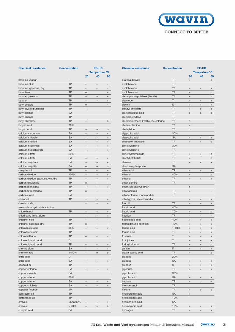
7 Chemical resistance
31 PE Soil Waste and Vent applications Product amp Technical Manual
Chemical resistance Concentration PE-HD Temperture ordmC 20 40 60 bromine vapour ndash
bromine fluid TP ndash ndash ndash
bromine gaseous dry TP ndash ndash ndash
butadiene TP o ndash
butane gaseous TP + + +
butanol TP + + +
butyl acetate TP o ndash
butyl glycol (butandiol) TP +
butyl phenol SA
butyl phenol TP
butyl phthalate TP + o
butyric acid 20
butyric acid TP + + o
calcium carbonate SA + + +
calcium chlorate SA + + +
calcium choride SA + + +
calcium hydroxide SA + + +
calcium hypochloride SA + + +
calcium nitrate 50
calcium nitrate SA + + +
calcium sulphate SA + + +
calcium sulphite SA o o o
camphor oil TP ndash ndash ndash
carbon dioxide 100 + + +
carbon dioxide gaseous wetdry TP + + +
carbon disulphide TP o ndash ndash
carbon monoxide TP + + +
carbon tetrachloride TP o ndash ndash
carbonic acid SA
castor oil TP + + +
caustic soda + + +
see sodium hydroxide solution
chlorethanol TP + + +
chlorinated lime slurry ndash + + +
chlorine fluid TP ndash ndash ndash
chlorine gaseous dry TP o ndash ndash
chloroacetic acid 85 + + +
chloroacetic acid TP
chloromethane TP o ndash ndash
chlorosulphuric acid D
chlorosulphuric acid TP ndash ndash ndash
chrome alum SA + + +
chromic acid 1ndash50 + o o
citric acid D
citric acid SA + + +
coconut oil TP
copper chloride SA + + +
copper cyanide SA
copper nitrate 30
copper nitrate SA + + +
copper sulphate SA + + +
coppper fluoride 2
corn germ oil TP
cottonseed oil TP
cresole up to 90 + + +
cresole gt 90 + + o
cresylic acid SA
Chemical resistance Concentration PE-HD Temperture ordmC 20 40 60 crotonaldehyde TP + o
cyclohexane TP
cyclohexanol TP + + +
cyclohexanon TP + o
decahydronaphtalene (decalin) TP + o
developer T + + +
dextrin D + + +
dibutyl phthalate TP + o o
dichloroacetic acid TP o o o
dichloroethylene TP
dichloromethane (methylene chloride) TP o ndash
diethanolamine TP +
diethylether TP o
diglycolic acid 30
diglycolic acid SA + + +
diisooctyl phthalate TP + + o
dimethylamine 30
dimethylamine TP
dimethylformamide TP + + o
dioctyl phthalate TP + o
dioxane TP + + +
disodium phosphate SA
ethanediol TP + + +
ethanol 40 + o
ethanol TP + + +
ethanolamine TP
ether see diethyl ether o
ethyl acetate TP + ndash
ethyl chloride mono and di TP
ethyl glycol see ethanediol + + +
flax oil TP + + +
fluoric acid 40
fluoric acid 70 + + o
fluoride TP ndash ndash ndash
fluorosilicic acid 40 + + +
formaldehyde (formalin) 40 + + +
formic acid 1ndash50 + + +
formic acid TP + + +
fructose T + + +
fruit juices T + + +
furfuryl alcohol TP + + o
gelatin D + + +
glacial acetic acid TP + o
glucose 20
glucose SA + + +
glucose D + + +
glycerine TP + + +
glycolic acid 30
glycolic acid SA + + +
heptane TP + o ndash
hexadecanol TP
hexane TP + o o
hydrobromic acid SA +
hydrobromic acid 10
hydrochloric acid SA
hydrocyanic acid 10 + + +
hydrogen TP + + +
32 PE Soil Waste and Vent applications Product amp Technical Manual Phone +31(0)38 42 94 951
Chemical resistance Concentration PE-HD Temperture ordmC 20 40 60 hydrogen bromide 50 + + +
hydrogen bromide TP + + +
hydrogen chloride damp TP + + +
hydrogen chloride dry TP
hydrogen peroxide 30 + + +
hydrogen peroxide 90 + 0 ndash
hydrogen sulphide 100 + + +
hydrogen sulphide SA
hydrogen sulphide TP + + +
iodine tincture T + o
i-propanol see isopropanol + + +
iron II chloride SA + + +
iron II sulphate SA + + +
iron III chloride SA + + +
iron III nitrate D + + +
iron III sulphate SA + + +
isopropanol TP
isopropylether TP
lactic acid 10
lactic acid TP + + +
lanolin (wool lipids) T + o o
lead acetate SA + + +
lead tetraethyl TP +
magnesium carbonate SA + + +
magnesium chloride SA + + +
magnesium hydroxide SA + + +
magnesium nitrate SA + + +
magnesium sulphate SA
maleic acid SA + + +
malic acid SA
mercury TP + + +
mercury chloride SA + + +
mercury cyanide SA + + +
mercury nitrate D + + +
methanol (methyl alcohol) TP + + o
methyl acetate TP + +
methyl bromide TP o ndash
methyl ethyl ketone TP + o
methyl methacrylate TP
methylamine up to 32 +
methylene chloride see dichloromethane o ndash ndash
milk T + + +
mineral oils T + + o
mineral water T + + +
molasses T + + +
muriatic acid up to 35 + + +
muriatic acid 20
muriatic acid dilute conc + + +
naphtha T + ndash ndash
naphthalene TP
nickel salts SA + + +
nicotinic acid D + +
nitric acid 10
nitric acid 25 + + +
nitric acid up to 40 o o ndash
nitric acid 10ndash50 o o ndash
Chemical resistance Concentration PE-HD Temperture ordmC 20 40 60 nitric acid more than 50 nitric acid 75 ndash ndash ndash
nitric acid 98
nitrobenzene TP + o o
n-propanol TP + + +
oils and fats (vegetableanimal) ndash + o o
oleic acid TP + + +
olive oil TP + + o
oxalic acid SA + + +
oxygen TP + + o
ozone TP o ndash ndash
paraffin oil TP + o o
peanut oil TP +
peppermint oil TP +
perchloric acid 10
perchloric acid 20 + + +
perchloric acid 70
perhydrol see hydrogen peroxide 30 + + +
petrol ether TP + o o
phenol D + + +
phenol dilute 90
phenylhydrazine TP
phenylhydrazine chlorohydrate TP
phosphine TP
phosphoric acid 50 + + +
phosphoric acid up to 85 + + o
phosphorus trichloride TP + + o
phosphoryl chloride TP + + o
picric acid SA + +
potable water chlorinated TP + + +
potash see potassium nitrate + + +
potassium bichromate 40
potassium bichromate SA + + +
potassium borate SA
potassium bromate SA + + +
potassium bromate 10
potassium bromide SA + + +
potassium carbonate and bi SA + + +
potassium chlorate SA + + +
potassium chloride SA + + +
potassium chromate 40 + + +
potassium cyanide gt10 + + +
potassium cyanide SA
potassium fluoride SA + + +
potassium hexacyanoferrate (II+III) SA + +
potassium hydroxide 60 + + +
potassium hydroxide up to 50 + + +
potassium hydroxide solution see potassium hydroxide
potassium hypochloride D + o
potassium iodide SA + + +
potassium nitrate (potash) SA + + +
potassium orothophosphate SA + + +
potassium perchlorate 1
potassium perchlorate 10
potassium perchlorate SA + + +
33 PE Soil Waste and Vent applications Product amp Technical Manual
Chemical resistance Concentration PE-HD Temperture ordmC 20 40 60 potassium permanganate SA
potassium permanganate 20 + + +
potassium persulphate SA + + +
potassium sulphate SA + + +
potassium sulphide D + + +
propane gaseous TR + +
proprionic acid 50 + + +
proprionic acid TP + o o
pyridine TP + o o
saccharic acid SA
salicylic acid SA + + +
sea water T + + +
sea water see ocean water + + +
silicone oil TP + + +
siliconic acid D + + +
silver acetate SA + + +
silver cyanide SA + + +
silver nitrate SA + + +
soap D
soda see sodium carbonate + + +
sodium acetate SA + + +
sodium benzoate SA + + +
sodium bicarbonate SA + + +
sodium biphosphate SA + + +
sodium borate SA
sodium bromide SA + + +
sodium carbonate SA + + +
sodium chlorate SA + + +
sodium chloride SA + + +
sodium chlorite 20
sodium cyanide SA + + +
sodium dichromate SA + + +
sodium fluoride SA + + +
sodium hexacyanoferrate (II + III) SA + + +
sodium hydrogen sulphite SA + + +
(sodium bisulphite)
sodium hydroxide solution up to 60 + + +
sodium hydroxide see sodium hydroxide solution + + +
sodium hypochloride 13 + + +
active chlorine
sodium nitrate SA + + +
sodium nitrite SA + + +
sodium orthophosphate SA + + +
sodium perborate SA + o
sodium phosphate SA + + +
sodium silicate (water glass) D + + +
sodium sulphate and bi SA + + +
sodium sulphide SA + + +
sodium sulphite 40
sodium thiosulphate SA + + +
soy bean oil TP + o o
strength D + + +
sugar SA + + +
sulphur dioxide dry wet TP + + +
sulphur dioxide fluid TP
sulphur trioxide TP ndash ndash ndash
Chemical resistance Concentration PE-HD Temperture ordmC 20 40 60sulphuric acid up to 10 sulphuric acid 10ndash80 + + +
sulphuric acid 96 o ndash
sulphurous acid SA
sulphurous acid 30 + + +
Superchloric acid see perchloric acid
table salt see sodium chloride + + +
tannic acid (tannins) D + + +
tartaric acid D + + +
tartaric acid SA
tetrahydrofuran TP o o ndash
tetrahydronaphthalene (tetralin) TP o o ndash
thionyl chloride TP ndash ndash ndash
thiophene TP o o ndash
tin chloride II + IV SA + + +
toluene TP o ndash ndash
trichloroacetic acid 50 + + +
trichloroethylene TP ndash ndash ndash
tricresyl phosphate TP + + +
triethanolamine D + o
trimethylol propane up to 10
turpentine oil TP o o o
urea 33
urea gt10 + + +
urea SA
urine T + + +
vinegar (wine vinegar) T + + +
vinyl acetate TP + + o
whisky T
wine and spirits T + + +
wine vinegar T + + +
xylene TP o ndash ndash
yeast D + + +
yeast SA
zinc carbonate SA + + +
zinc chloride SA + + +
zinc oxide SA + + +
zinc sulphate SA + + +
34 PE Soil Waste and Vent applications Product amp Technical Manual Phone +31(0)38 42 94 951
81Packaging
The packaging of Wavin domestic waste-water piping
systems is both user-friendly and transportation-orientated
The packaging is designed to ensure maximum safety and
easy storage and handling
82Transport
When loading and transporting Wavin domestic waste-water
piping not still in its original packing take care that the pipes
are supported along their entire length to avoid their being
bent Arrange the pipes such that they lie with their end
collars offset Avoid subjecting the pipes to impact stress
particularly when temperatures are low
Figure 31 Transporting loose Wavin waste-water pipes Figure 33 Pipes stored directly onto level flooring
Figure 34 Pipes stored on timber supporting frame
Figure 32 Unloading packaged waste-water piping
When using machinery to load and unload packaged piping ensure that the lifting forks are smooth and clean Where this is not the case support the packaging using nylon slings Steel cables chains hooks and other metallic lifting gear must not be used
83Pipestorage
Pipe deformation or other forms of permanent damage must
not be allowed to occur during storage Factory-delivered
piping palettes may be stacked to a height of 3 metres Loose
piping must be supported at the sides Supports must be pro-
vided at least every 2 metres This should be carried out using
battens and crossbeams with a minimum section of 75 mm
Caution
Short-term pipe deformation can occur where pipe stacks are
unevenly exposed to the effects of the sun (or other forms of
heat) Pipes should not therefore be stored in direct sunlight
Where it is not possible to store piping on completely level
flooring we recommend the use of a timber supporting frame
with crossbeams positioned at maximum intervals of 1 metre
(see diagram)
84Storingmouldedfittings
Fittings should be kept in their factory-delivered packaging
until required for use
8 Packaging transport and storage
35 PE Soil Waste and Vent applications Product amp Technical Manual
Pipe
Article code d1 di S1 L A cm2
920001 32 260 30 3000 53
920003 40 340 30 5000 90
920005 50 440 30 5000 152
920006 56 500 30 5000 231
920007 63 570 30 5000 254
920008 75 690 30 5000 373
920009 90 830 35 5000 541
920010 110 1014 43 5000 807
920011 125 1152 49 5000 1042
920013 160 1476 62 5000 1711
920015 200 1876 62 5000 2764
920017 250 2344 78 5000 4315
920019 315 2954 98 5000 6853
Concentricreducer
Article code d1d2 X1 X2 H920508 4032 30 30 80
920516 5040 30 30 80
920522 5650 30 30 80
920525 6340 30 30 80
920526 6350 30 30 80
920527 6356 30 30 80
920530 7540 30 30 80
920531 7550 30 30 80
920533 7563 30 30 80
920535 9040 30 30 80
920536 9050 30 30 80
920538 9063 30 30 80
920539 9075 30 30 80
920542 11040 30 30 80
920543 11050 30 30 80
920544 11056 30 30 80
920545 11063 30 30 80
920546 11075 30 30 80
920547 11090 30 30 80
920550 12550 30 30 80
920552 12563 30 30 80
920553 12575 30 30 80
920554 12590 30 30 80
920555 125110 30 30 80
920558 160110 32 29 100
920560 160125 32 32 100
920562S 200160 100 100 250
920564S 250200 120 120 270
920566S 315250 130 130 325S = Segment Welded
9 Products
Pipes From Oslash 75 to Oslash 160 pipe series S125 PN 5 From Oslash 200 to
Oslash 315 pipe series S16 PN 4
Nominal diameters according to DIN 19535
Wavin PE standard pipes are supplied in 5 meter
lengths marked with co-extruded green lines
Exception 32 mm pipes are supplied in 3 meter lengths
36 PE Soil Waste and Vent applications Product amp Technical Manual Phone +31(0)38 42 94 951
Eccentricreducer-short
Article code d1d2 X1 X2 H920608 4032 1255 1255 65
920616 5040 35 37 80
920620 5640 35 37 80
920622 5656 35 37 80
920625 6340 35 37 80
920626 6350 35 37 80
920627 6356 35 37 80
920630 7540 33 30 80
920631 7550 35 37 80
920632 7556 35 37 80
920633 7563 35 37 80
920635 9040 30 34 80
920636 9050 31 34 80
920637 9056 31 36 80
920638 9063 31 38 80
920639 9075 31 43 80
920642 11040 31 34 80
920643 11050 31 34 80
920644 11056 31 35 80
920645 11063 35 37 80
920646 11075 31 36 80
920647 11090 35 37 80
920653 12575 35 30 80
920654 12590 35 32 80
920655 125110 36 36 80
920671 160110 35 37 80
920672 160125 35 37 80
Eccentricreducer-short
Article code d1d2 X1 X2 H920675 200110 110 60 325
920676 200125 110 70 310
920678 200160 110 90 270
920690S 250200 130 110 325
920698S 315250 150 130 395
Elbowlargerthickness15ordm
Article code d1 part X1 r921542 110 15deg 45 80
S = Segment Welded
9 Products
37 PE Soil Waste and Vent applications Product amp Technical Manual
Elbow45ordm
Article code d1 X1
921232 32 25
921234 40 40
921254 50 45
921264 56 45
921274 63 50
921284 75 50
921294 90 55
921304 110 60
921314 125 65
921334 160 100
921354 (short radius) 200 160
921 374S 250 165
921 394S 315 230
Elbow885ordm
Article code d1 X1921238 40 60
921258 50 70
921268 56 40
921519 63 80
921528 75 75
921538 90 100
921298 90 80
921548 110 110
921558 125 125
921568 160 180
Elbow90ordmsegmentwelded
Article code d1 X1921013 160 140
921015S 200 250
921017S 250 335
921019S 315 370
Swept type
S = Segment Welded
38 PE Soil Waste and Vent applications Product amp Technical Manual Phone +31(0)38 42 94 951
Elbow90ordmextended
Article code d1 X1 X2 r921002 32 100 30 30
921003 40 150 30 30
921005 50 180 40 40
921006 56 210 40 40
921007 63 210 50 50
921008 75 210 70 70
921009 90 240 90 90
921010 110 270 103 100
921011 125 200 110 110
Elbowlargerthickness885ordm
Article code d1 X1921548 40 45
Reducedelbow90ordm
Article code d1d2 X1-X2 r 921716 5040 50 50
PEAirmixldquoSoventrdquo
Article code di922991 110
922992 160
9 Products
39 PE Soil Waste and Vent applications Product amp Technical Manual
Airybranch885ordm
Article code d1d2 X1 X2 X3 H922280 110 170 140 100 270
Doublebranch45ordm
Article code d1d2 X1 X2-X3 H922336 9050 80 160 240
922343 11050 80 180 260
922348 110110 80 180 260
922350 125110 100 200 300
Y-Branch30ordm
Article code d1d2 X1 X2
922818 5050 45 95
922848 110110 90 120
Branch45ordm
Article code d1d2 X1 X2-X3 H
922005 3232 35 70 105
922008 4032 45 90 135
922009 4040 45 90 135
922016 5040 55 110 165
922018 5050 55 110 165
922022 5650 60 120 180
922023 5656 60 120 180
922025 6340 65 130 195
922026 6350 65 130 195
922027 6356 65 130 195
922028 6363 65 130 195
922030 7540 70 140 210
922031 7550 70 140 210
922032 7556 70 140 210
922033 7563 70 140 210
922034 7575 70 140 210
40 PE Soil Waste and Vent applications Product amp Technical Manual Phone +31(0)38 42 94 951
922035 9040 80 160 240
922036 9050 80 160 240
922038 9063 80 160 240
922039 9075 80 160 240
922040 9090 80 160 240
922042 11040 90 180 270
922043 11050 90 180 270
922045 11063 90 180 270
922046 11075 90 180 270
922047 11090 90 180 270
922048 110110 90 180 270
922050 12550 100 200 300
922052 12563 100 200 300
922053 12575 100 200 300
922054 12590 100 200 300
922055 125110 100 200 300
922056 125125 100 200 300
922071 160110 125 250 375
922072 160125 125 250 375
922074 160160 125 250 375
922075 200110 180 360 540
922076S 200125 180 360 540
922078S 200160 180 360 540
922079S 200200 180 360 540
922086S 250110 220 440 660
922087S 250125 220 440 660
922089S 250160 220 440 660
922090S 250200 220 440 660
922092S 250250 220 440 660
922093S 315110 280 560 840
922094S 315125 280 560 840
922095S 315160 280 560 840
922096S 315200 280 560 840
922098S 315250 280 560 840
922099S 315315 280 560 840
Branch885ordm
Article code d1d2 X1 X2-X3 H
922205 3232 50 50 100
922208 4032 75 55 130
922209 4040 75 55 130
922216 5040 90 60 150
922218 5050 90 60 150
922222 5650 105 70 175
922223 5656 105 70 175
S = Segment Welded
9 Products
41 PE Soil Waste and Vent applications Product amp Technical Manual
Branch885ordm(continued)
Article code d1d2 X1 X2-X3 H 922225 6340 105 70 175
922226 6350 105 70 175
922228 6363 105 70 175
922230 7540 105 70 175
922231 7550 105 70 175
922232 7556 105 70 175
922233 7563 105 70 175
922234 7575 105 70 175
922235 9040 120 80 200
922236 9050 120 80 200
922238 9063 120 80 200
922239 9075 120 80 200
922240 9090 120 80 200
922242 11040 135 90 225
922243 11050 135 90 225
922244 11056 135 90 225
922245 11063 135 90 225
922246 11075 135 90 225
922247 11090 135 90 225
922248 110110 135 90 225
922252 12563 150 100 250
922253 12575 150 100 250
922254 12590 150 100 250
922255 125110 150 100 250
922256 125125 150 100 250
922271 160110 210 140 350
922272 160125 210 140 350
922274 160160 210 140 350
922275S 200110 180 180 360
922276S 200125 180 180 360
922278S 200160 180 180 360
922279S 200200 180 180 360
922286S 250110 220 220 440
922287S 250125 220 220 440
922289S 250160 220 220 440
922290S 250200 220 220 440
922292S 250250 220 220 440
922293S 315110 280 280 560
922294S 315125 280 280 560
922295S 315160 280 280 560
922296S 315200 280 280 560
922298S 315250 280 280 560
922299S 315315 280 280 560
S = Segment Welded
42 PE Soil Waste and Vent applications Product amp Technical Manual Phone +31(0)38 42 94 951
BracketInsert
Article code oslash305504 40305505 50305506 63305507 75305508 90305509 110305510 125305511 160305512 200
GalavanisedPEBracket
Article code oslash305014 40 x frac12305015 50 x frac12305016 63 x frac12305017 75 x frac12305018 90 x frac12305019 110 x frac12305020 125 x frac12305021 160 x frac12305025 200 x 1305026 250 x 1305027 315 x 1
GalavanisedPEBracketM10connection
Article code oslash305004 40305005 50305006 63305007 75305008 90305009 110305010 125305011 160
FireCollarEFM
Article code oslash309180 40x63309182 75309183 78x90309184 110309185 125309186 135x160309187 200309188 250
9 Products
43 PE Soil Waste and Vent applications Product amp Technical Manual
Sphericalbranch2stubs
TypeA-180deg
Article code d1d2-d3 X1 X2-X3 H922443 11050 100 120 200
922446 11075 100 120 200
922447 11090 100 120 200
922448 110110 100 120 200
922455 125110 100 125 200
TypeB-90deg
Article code d1d2-d3 X1 X2-X3 H922517 11050 100 120 200
922519 11063 100 120 200
922521 11090 100 120 200
922522 110110 100 120 200
922528 125110 100 125 200
TypeC-135deg
Article code d1d2-d3 X1 X2-X3 H922572 110110 100 120 200
44 PE Soil Waste and Vent applications Product amp Technical Manual Phone +31(0)38 42 94 951
Sphericalbranch3stubs
TypeD-135deg
Article code d1d2-d3 X1 X2-X3 H922672 110110 100 120 200
TypeE-90deg
Article code d1d2-d3 X1 X2-X3 H922622 110110 100 120 200
922628 125110 100 125 200
Sphericalbranch4stubs
TypeF-90deg
Article code d1d2-d3 X1 X2-X3 H922721 11090 100 120 200
922722 110110 100 120 200
9 Products
45 PE Soil Waste and Vent applications Product amp Technical Manual
AccessTee45deg
Article code d1d2 X1 X2 X3 H920711 110110 90 230 180 270
920712 125110 100 250 200 300
920716 160110 125 300 250 375
AccessTee885deg
Article code d1d2 X1 X2 X3 H920863 4040 75 70 50 125
920865 5050 90 85 60 150
920867 6363 105 80 70 175
920868 7575 105 90 70 175
920869 9090 120 100 80 200
920870 110110 135 125 90 225
920871S 125110 150 130 100 250
920873S 160110 210 150 140 350
920875S 200110 180 170 180 360
920877S 250110 220 190 220 440
920879S 315110 280 210 280 560
Floor-mountedtoiletconnector
Article code d1de t H923006 90120 95 125
923016 110120 95 125
Constantdiametertoiletelbow90ordm
Article code d1 X1 X2923097 110 300 180
Connectingelbow90ordmsmooth
Article code d1 X1 X2921139 90 270 50
921140 110 300 60
S = Segment Welded
46 PE Soil Waste and Vent applications Product amp Technical Manual Phone +31(0)38 42 94 951
Toiletelbow885ordmsmoothTypeA
Article code d1de X1 t H923072 90132 270 60 120
Toiletelbow885ordmextendedTypeB
Article code d1de X1 t H4923057 923057 90120 270 120 160
4923067 923067 110120 300 120 185
with notch
UniversaltoiletelbowTypeC
Article code d1de X1 t H923087 110132 300 120 185
Longspigottoiletelbowwithrightstubs
Article code d1d2 de X1 X2 t H926002 9040 120 270 180 120 160
926004 9050 120 270 180 120 160
926008 11050 120 300 150 140 185
Oslash 190 with notch
Oslash 110 with asymmetrical junction
Longspigottoiletelbowwithleftstubs
Article code d1d2 de X1 X2 t H926001 9040 120 270 180 120 160
926003 9050 120 270 180 120 160
926007 11050 120 300 150 140 185
Oslash 190 with notch
Oslash 110 with asymmetrical junction
9 Products
47 PE Soil Waste and Vent applications Product amp Technical Manual
Longspigottoiletelbowwithdoublestubs
Article code d1d2 de X1 X2 t H926010 9040 120 270 180 120 160
926011 9050 120 270 180 120 160
926012 11040 120 300 150 140 185
926013 11050 120 300 150 140 185
Oslash 190 with notch
Oslash 110 with asymmetrical junction
Longspigottoiletelbowwith4stubs
Article code d1d2 de X1 X2 t H923107 11040 120 300 150 140 185
923108 11050 120 300 150 140 185
Floormountedtoiletconnectiongasket
Article code d Type of connection
308020 120 Toilet elbow - Type B
308010 135 C elbow - Type A - C
308107 107 Floor mounted elbow
Allows the connection between the toilet discharge fitting and
the long toilet elbow
Wallmountedtoiletconnector
Article code d1di de t H924227 9090 110 28 38
924228 110110 131 28 38
48 PE Soil Waste and Vent applications Product amp Technical Manual Phone +31(0)38 42 94 951
Wallmountedtoiletconnectorelbow90ordmforhangingtoilets
Article code d1di de X1 t H923281 9090 110 225 34 75
923280 11090 110 225 34 75
923285 110110 131 300 33 75
Wallmounteddoubletoiletconnectorelbow90ordm
Article code d1di de X1 t H923358 110110 131 195 28 270
Toiletwallmountedconnectorleft
Article code d1di de X1 X2 t H923317 110110 131 310 100 28 95
Toiletwallmountedconnectorright
Article code d1di de X1 X2 t H923327 110110 131 310 100 28 95
Toiletwallconnectordouble
Article code d1di de X1 X2 t H923337 110110 131 340 100 28 270
All fittings are supplied with gasket and protection cap
9 Products
49 PE Soil Waste and Vent applications Product amp Technical Manual
Lavatorypantrap
Article code d1 de a X1 t H923558 90 132 45deg 330 60 145
923551 110 132 0deg 290 60 165
923552 110 132 45deg 380 60 165
923555 110 132 90deg 330 60 165
TrapldquoFirenzerdquo
Article code d1 X1 H929992 110 580 200
929993 125 720 250
Outletconnector
Article code d1di t H923606 4046 25 35
923612 5046 25 35
Outletconnectorelebow
Article code d1di X1 t H923623 3246 60 20 50
923626 4046 60 20 50
923632 5046 60 20 50
RubbergasketUniversaltypeArticle code d d1308042 46 1rdquo - 1 frac14rdquo
308044 46 1 frac12rdquo
50 PE Soil Waste and Vent applications Product amp Technical Manual Phone +31(0)38 42 94 951
Electro-fusioncouplerUniversaltype(WAVIDUO)
Article code d1 de H910104 40 54 52
910105 50 64 52
910106 63 77 52
910107 75 90 52
910108 56 68 52
910109 90 104 54
910111 110 124 64
910112 125 143 64
910116 160 180 63
910120 200 244 208
910125 250 304 244
910131 315 382 268
To be welded with
Electro-fusion welding machine DUO 315 (reference nr 711315)
Push-fitsocketwithgasketandcap
Article code d1di de t H924202 3232 47 35 50
924203 4040 57 50 85
924205 5050 67 50 85
924206 5656 57 52 85
924207 6363 79 52 85
924208 7575 92 65 100
924209 9090 110 70 105
924210 110110 131 70 105
924211 125125 150 75 115
924213 160160 190 93 140
9 Products
51 PE Soil Waste and Vent applications Product amp Technical Manual
Expansionsocketwithgasketandcap
Article code d1di de t H924103 4040 57 170 235
924105 5050 67 170 235
924106 5656 57 170 235
924107 6363 80 175 235
924108 7575 92 179 240
924109 9090 110 175 240
924110 110110 130 178 255
924111 125125 148 180 255
924113 160160 188 190 285
924115S 200200 225 200 345
924117 250250 280 250 405
924119 315315 350 250 405
The expansion sockets from 40 to 315 mm absorb the expansion and the contraction of a 5000 mm long pipe 10degC temperature difference = 2 mm expansion or contraction per meter On the expansion socket the push-in depth of the pipe at a room temperature of 0degC and + 20degC is mentioned
Push-fit depth in mm Oslash -10deg 0deg +10deg +20deg 40 - 160 70 80 90 105
200 - 315 170 180 190 205
The expansion socket Oslash 110 has an external ring for fixed-point bracket
Completescrewconnection
Article code d1 de h H924303 40 64 30 50
924306 50 74 34 58
924310 63 87 36 63
924311 75 103 42 65
924312 90 125 46 82
924313 110 145 57 90
Bush
Article code d1 X1 H924363 40 29 62
924366 50 33 70
924370 63 37 79
924371 75 38 81
924372 90 48 101
924373 110 52 110
S = Segment Welded
52 PE Soil Waste and Vent applications Product amp Technical Manual Phone +31(0)38 42 94 951
Completeclosingcap
Article code d1 de H924443 40 64 45
924446 50 74 55
924450 63 87 40
924451 75 103 45
924452 90 123 45
924453 110 145 50
Weldcap
Article code d1 H924622 32 5
924623 40 38
924625 50 38
924627 63 38
924628 75 38
924629 90 40
924630 110 45
924631 125 46
924633 160 48
Protectioncapforpipesandfitting
Article code d1 H929004 40 30
929005 50 30
929006 63 30
929007 75 30
929009 90 31
929011 110 33
929012 125 36
929016 160 36
Flangeconnection
9 Products
53 PE Soil Waste and Vent applications Product amp Technical Manual
Flangealuminiumcoated
Article code d1 di de K S bolts no thread 309121 50 62 150 110 16 4 M16
309122 56-63 78 165 125 16 4 M16
309123 75 92 185 145 16 4 M16
309124 90 108 200 160 18 8 M16
309125 110 128 220 180 22 8 M16
309127 125 135 220 180 22 8 M16
309128 160 178 285 240 24 8 M20
309129 200 235 340 295 26 8 M20
309119 250 288 395 350 28 12 M20
309120 315 338 445 400 28 12 M20
Flangeadaptor
Article code d1 de h H926521 50 88 17 60
926522 63 102 19 65
926523 75 122 21 70
926524 90 138 22 70
926525 110 158 24 80
926527 125 158 24 80
926526 125 188 24 80
926528 160 212 24 85
926529 200 268 24 140
926519 250 320 27 145
926520 315 370 27 145
Flatgasketforblindflanges
Article code d1 di de S309250 250 252 328 4
309251 315 302 378 4
Note for diameter 50-200 mm use the gasket EPDM from
Wavin PE80-PE100 product range Please see below
EPDMArticle code d1 de S904402 132 170 3
904403 140 182 3
904404 150 192 3
904405 163 107 3
904406 175 127 3
904407 190 142 3
904408 110 162 3
904462 160 218 3
904463 200225 273 4
54 PE Soil Waste and Vent applications Product amp Technical Manual Phone +31(0)38 42 94 951
Brassnutconnection
Article code d1 G H924734 40 34rdquo 60
924735 40 1rdquo 60
924736 40 1- frac14rdquo 60
924737 40 1- frac12rdquo 60
924743 50 frac34rdquo 75
924755 50 1rdquo 60
924756 50 1- frac14rdquo 60
924757 50 1- frac12rdquo 60
924758 50 2rdquo 60
924760 63 2rdquo 82
Internalthreadjoint
Article code d1 G t H307031 40 frac12rdquo 20 55
307033 40 frac34rdquo 20 55
307035 40 1rdquo 20 55
307039 50 frac12rdquo 20 55
307041 50 frac34rdquo 22 55
307043 50 1rdquo 24 55
307045 50 1-frac14rdquo 20 55
307047 50 1-frac12rdquo 22 55
307049 50 2rdquo 24 87
307051 63 2rdquo 24 94
Externalthreadjoint
Article code d1 G t H307060 50 1-frac14rdquo 25 60
307062 50 1-frac12rdquo 26 60
307064 63 2rdquo 25 60
Shrink-onsocketwithseal
Article code d1 di t H Oslash connection925915 50 68 80 250 45 divide 60
925917 63 91 85 250 60 divide 82
925918 75 100 90 250 70 divide 92
925919 90 111 100 250 85 divide 102
925920 110 132 90 250 105 divide 124
925921 125 156 100 250 120 divide 148
925922 160 180 100 250 155 divide 172
925916 200 220 100 250 195 divide 212
Other Oslash on request
9 Products
55 PE Soil Waste and Vent applications Product amp Technical Manual
AdaptortoPVC
Article code d1d2 t H925925 110100 75 105
Connectorwith4stubs
Article code d1d2 X1 X2 H929997 11040 100 105 500
929998 11050 100 105 500
Bathtrap-Withjointand1rdquofrac14brassnut
bull Black solderable HD PE
bull Rotation horizontal ~ 208deg - vertical ~ 10deg
bull Self-cleaning
bull Double seal
bull DN 4050 joint
Article code M852
Bathtrap-Withjointand1rdquofrac12brassnut
bull Black solderable HD PE
bull Rotation horizontal ~ 208deg - vertical ~ 10deg
bull Self-cleaning
bull Double seal
bull DN 4050 joint
Article code M853
Floordrain-SmalldrainwithDN4050outlet
bull Black solderable HD PE
bull Adjustable backflow prevention device
Article code M611
SPARES M6111 100 x 100 mm grill
M6113 Filter
M6112 100 x 100 mm filter holder
56 PE Soil Waste and Vent applications Product amp Technical Manual Phone +31(0)38 42 94 951
Floordrain-SmalldrainwithjointandDN4050outlet
bull Black solderable HD PE
bull Self-cleaning
bull Double seal
Article code M71640
SPARES M6111 100 x 100 mm grill
M6113 Filter
M6112 100 x 100 mm filter holder
Floordrain-Largedrain
bull Black solderable HD PE
bull Adjustable
Article code M713
SPARES M6111 100 x 100 mm grill
M6113 Filter
M6112 100 x 100 mm filter holder
Showertrap-WithDN80inlet
bull Black solderable HD PE
bull Rotation horizontal ~ 270deg - vertical ~ 10deg
bull Self-cleaning
bull Double seal
bull DN 4050 joint
Article code M655
SPARES M6111 100 x 100 mm grill
M6113 Filter
M6112 100 x 100 mm filter holder
9 Products
57 PE Soil Waste and Vent applications Product amp Technical Manual
Floortrap-HDPE4-waywithgrillandtrap
bull Black solderable HD PE
bull Adjustable check valve 1048576H 53 mm
bull 3 DN 40 inlets and 1 DN 50 outlet Inlets require boring
Article code M612
SPARES M6121 140 x 140 mm grill
M6122 Grill holder
M6125 Open seal
Floortrap-HighHDPE4-way
bull Black solderable HD PE
bull 3 DN 40 inlets and 1 DN 50 outlet
Inlets require boring
Article code M618
58 PE Soil Waste and Vent applications Product amp Technical Manual Phone +31(0)38 42 94 951
Weldingequipment
Electroweldingmachine-DUO315machine
Article code Oslash Description 711315 40 ndash 315 WaviDuo machine
710001 40 ndash 160 Fusion Cable Green
710002 200 ndash 315 Fusion Cable Brown
710003 40 ndash 160 Serial Fusion Cable
710004 Transport Box Blue
Supply voltage 220 V~ 50 Hz
Weldingmirrorcompletewithmetalcase
Article code Oslash Welding
700 016 200
700 017 300
- with termostat - teflon-coated
- complete with supports - metal carrying case
- 800 W - supply voltage 220 V ~ 50 Hz
Universal160
Article code Oslash Description700054 40 divide 160 Welding machine
701022 40 divide 160 Spare blade
Welding machine provided with- teflon-coated thermoplate 220 V 800 W self-centering
- motorized facing miller supplied with rightleft lock
- carriage with rack and check of the constant pressure
- jaws which can weld (by universal welding) branches 45deg 60deg 885deg fittings elbows
and pipes from Oslash 40 - 160 mm
9 Products
59 PE Soil Waste and Vent applications Product amp Technical Manual
Media250
Article code Oslash Description700002 75 divide 250 Welding machine
701024 75 divide 250 Spare blade
Welding machine provided with
- electric rotary planer with microswitch incorporated in the handle
- teflon-coated thermoplate Oslash 300 - 200 V 1300 W
- set of jaws Oslash 250 and reducers to be used for welding diameters
7590110125160200
Maxi315
Article code Oslash Description700003 125 divide 315 Welding machine
701026 125 divide 315 Spare blade
Welding machine provided with- electric rotary planer with microswitch incorporated in the handle
- teflon-coated thermoplate Oslash 340 - 220 V 1800 W
- set of jaws and reducers to be used for welding diameters 315250200160125
- assembled on trolley
1503
15
-071
-
M
arch
201
5
Discoverourbroadportfolioatwavincom
Hot amp Cold Water
Indoor Climate
Soil amp Waste
Foul Water
Storm Water
Gas amp Water Mains
Geotextiles
92
Wavin operates a programme of continuous product development and therefore reserves the right to modify or amend the specification of their products without notice All information in this publication is given in good faith and believed to be correct at the time of going to press However no responsibility can be accepted for any errors omissions or incorrect assumptions
copy 2019 Wavin Wavin reserves the right to make alterations without prior notice Due to continuous product development changes in technical spefications may change Installation must comply with the installation instructions
wavinasia
Wavin is part of Orbia a communityof companies working togetherto tackle some of the worldrsquos mostcomplex challenges We arebound by a common purposeTo Advance Life Around the World
WAVIN ASIA PACIFIC E-mail wavinapacwavincom | Internet wwwwavincomasia

2 PE Soil Waste and Vent applications Product amp Technical Manual Phone +31(0)38 42 94 951
Introduction page 4
1 WavinPESoilWasteandVentsystems page 5
11 Systemdescription page 5
12 Materialcharacteristics page 5
13 Applications page 6
14 Productspecifications page 6
2 Assembly page 8
21 General page 8
211 Pipeworkinthewasteremovalsystem page 8
212 Brackets page 8
213 Storage page 8
214 Ovalpipeends page 8
215 Shorteningpipes page 8
22 Jointing page 8
221 Principlesofheatfushing
polyethylenepipesandfittings page 8
222 Butt-welding page 9
223 Electrofusion page 12
3 Installation page 15
31 Installationusingflexionlegsexpansionbends page 15
32 Operationtreatmentandinstallationoflongpipecollars page 15
33 Rigidinstallationofopen-mountedPEpiping page 17
34 Securingusingfixingpoints page 17
35 Installationofexpansionjoints page 18
36 InstallationofWavinfireprotectionsleeves page 19
361 WavinBM-R90fireprotectionsleeve page 19
3611BM-R90Installationinstructions page 19
3612Components page 20
3613Typesofinstallation page 20
362 WavinBB-R90fireprotectiontape page 24
Contents
3 PE Soil Waste and Vent applications Product amp Technical Manual
37 WavinPEAirmixSoventfitting page 26
371 Introduction page 26
372 Benefits page 26
373 Applications page 26
38 Castinginheatcuredconcreteandextrusionshrinkage page 26
39 Cast-inpipework page 27
391 Layingofsewagepipes page 27
392 Inspectionshafts page 29
4 Situationsduringconstruction page 28
5 Pressuretesting page 28
6 Maintenance page 29
7 Chemicalresistance page 30
8 Packagingtransportandstorage page 34
81 Packaging page 34
82 Transport page 34
83 Pipestorage page 34
84 Storingmouldedparts page 34
9 Productlist page 35
4 PE Soil Waste and Vent applications Product amp Technical Manual Phone +31(0)38 42 94 951
WavinPEProductampTechnicalGuide
This technical manual on PE above-ground drainage systems
deals with the removal of domestic waste water and rainwater
from houses and residential and commercial properties using
plastic piping systems
It covers all aspects from design to installation The manual is
intended for clients architects construction specialists building
co-operatives building inspectors and of course for instal-
lers If you have any questions wishes or practical problems
not covered by this manual then we would ask you to submit
them to us together with any suggestions for amendments
and additions
Since our systems are often utilised in circumstances beyond
our control we cannot accept liability for the consequences of
applying the information provided in this manual This edition
of the manual supersedes all previously published technical
data
Introduction
5 PE Soil Waste and Vent applications Product amp Technical Manual
11Systemdescription
Wavin PE is a universal system approved for pipe installation
in buildings to DIN 19535 and DIN EN 1519 and for under-
ground pipes to DIN EN 12666 The product range includes
pipes and fittings with dimensions between 40 and 315 mm
Wavin PE is a complete soil waste and vent system of pipes
and fittings manufactured from high-density polyethylene
(PE HD) This tough and durable PE system offers an extra-
ordinary chemical resistance in combination with a high flexi-
bility level and great impact resistance Wavin PE pipes and
fittings are jointed by welding making the joints resistant to
tension There are two methods of welding butt welding and
electro-fusion welding Most Wavin PE products can also be
used as part of under-pressure installations like the siphonic
roof drainage system Wavin QuickStream
12Materialcharacteristics
High-temperature resistance
Wavin PE guarantees resistance to
temperatures of up to 100degC and is suitable
for washing-machine and dishwasher
drainpipes
Flexibility
Wavin PE is well suited to assemblies
subjected to vibration It is therefore ideal
for use in seismic zones and across
expansion joints
UV resistance
With the addition of a percentage of carbon
black PE is UV-stabilised and can therefore
be installed outdoors without degradation
problems
Ease of welding
An advantage of Wavin PE is that it can
be welded (both by butt welding and with
electrofusion joints) thereby providing a
perfectly sealed system
Low weight
Wavin PErsquos lightness makes transportation
and handling easy
Use of adhesives
Because of its high resistance to chemical
agents Wavin PE cannot be jointed with
adhesives
Low-temperature resistance
The elasticity of Wavin PE allows pipes to
withstand freezing of internal water
Impact resistance
Wavin PErsquos elasticity gives pipes a high
impact strength at temperatures as low as
-40degC This ruggedness makes handling of
pipes easy during installation
Blockage-free
The smooth surface of Wavin PE allows for
both an optimum flow of any type of waste
material and self-cleaning of pipes
Fire Hazards
Wavin PE does not issue any toxic gases
during combustion
Wavin PE connection seals
Quick-fit coupling and expansion joint seals
remain resistant to all chemical agents
even if only slightly wetted by waste water
The seals are produced from an elastomer
which guarantees sealing and durability
even in extreme conditions
1 Wavin PE Soil Waste and Vent system
6 PE Soil Waste and Vent applications Product amp Technical Manual Phone +31(0)38 42 94 951
13Applications
Domestic waste-water system
Tensile resistant joint technology guarantees the highest
levels of leakage security The Wavin PE waste-water piping
system complies with DIN 19535 and DIN EN 1519 and is
resistant to the effects of hot water It meets the requirements
of DIN EN 12056 and DIN 1986 -100 (95deg short-term loading)
Rainwater piping
Wavin PE waste-water piping is suitable for use on rainwater
drainage systems PE piping can be used in low-pressure
systems to drain free surface waters and rainwater (see the
Wavin QuickStream technical handbook)
Underground piping
The options for using PE piping systems for underground drai-
nage are outlined in DIN 12666 -12005 This standard defines
parameters such as pipe diameter wall thickness and rigidity
Minimum ring stiffness standards of SN 4 (4 KNm2) are
required for all ldquoUldquo-category applications (external under-
ground piping) The Wavin PE (110 ndash 315 mm) waste-water
system complies with the SN 4 (4 KNm2) ring stiffness spe-
cifications Pipe range lt SDR 26 (eg SDR 33SN2) is not
suitable for underground applications Data on SDR and ring
stiffness specifications can be found in the pipe data table
Industrial waste-water
The Wavin PE system is resistant to aggressive chemicals
Further details about the chemical resistance of PE-HD can
be found in chapter 7 on page 31 and in the Wavin ldquoChemical
Resistancerdquo data sheet
Pumping systems
PE waste-water systems are primarily used on non-pressu-
rised applications However they can also be used without
hesitation on systems subject to short-term pressure loading
(ie pumping systems) They are capable of handling maxi-
mum internal pressures of 15 bar Installation and fixing must
be carried out in accordance with the given specifications
Manufacture and testing
Wavin PE piping complies with the technical specifications in
DIN EN 1519 and DIN 19535 Part 2 as tested by the National
Materials Testing Facility
14Productspecifications
Basic material
Wavin PE waste-water pipes and fittings are manufactured
from PE - HD material
Colour
Black
Identification and labelling
Wavin PE nominal diameters year of manufacture material
supervision marks fire category B2
Example Wavin PE EN 1519 IIP 152 UNI Ue DIN 19535 DN
100 110 x 43 PE BD S 125 weldable tempered A-M-G-T
Properties
Melt flow index 03 ndash 089 g10 min
Coefficient of expansion 02 mmm degC
UV resistance given by carbon content
of 2 ndash 25
Fire behaviour DIN 4102 B2
7 PE Soil Waste and Vent applications Product amp Technical Manual
Quality assurance
All piping and fittings are subject to continuous internal quality
control procedures The system is also subject to external
monitoring by the Materials Testing Facility The system
conforms to the established technical specifications set out
in Building Regulations A Part 1 Issue 20031 No1218 and
comply with
DIN EN 1519 - 12001-01 and
DIN 19535 - 10200-01
Information on the transportation and
storage of PE pipes and fittings
PE pipes must be protected against damage during trans-
portation and especially during loading and unloading Prior
to any unloading pipes should be carefully inspected for
damage incurred during transportation Where lifting gear is
to be employed the use of wide belts and slings is recom-
mended Unpaletted pipes should wherever possible be
supported along their entire length and prevented from rolling
against each other Pipe storage areas and supporting surfa-
ces should be free from sharp edges
Caution
Short-term pipe deformation can occur where pipes are
unevenly exposed to the effects of the sun (or other forms
of heat) Pipes should therefore not be stored in direct
sunlight
d
s
di
SDR = dis
Pipe data
Calculating SDR category
DN d1 di2 s3 SDR4 SN
mm mm mm
40 40 340 30 136 -
50 50 440 30 17 -
56 56 500 30 17 -
60 63 570 30 21 -
70 75 690 30 26 -
90 90 830 35 26 4
100 110 1014 43 26 4
125 125 1152 49 26 4
150 160 1476 62 26 4
200 200 1876 62 33 2
200 200 1846 77 26 4
250 250 2344 78 33 2
250 250 2308 96 26 4
300 315 2954 98 33 2
300 315 2908 121 26 4
1) external diameter in mm
2) internal diameter in mm
3) wall thickness in mm
4) SDR category
5) Max pressure in mbar
Table 1
8 PE Soil Waste and Vent applications Product amp Technical Manual Phone +31(0)38 42 94 951
As well as the design of the installation there is also the actual
assembly The design is complete but many decisions remain
to be taken by the fitter which will impact on the quality of the
work and the problem-free operation of the waste removal
system
21General
211Pipeworkinthewasteremovalsystem
The pipework must be installed with a particular fall as indi-
cated on the drawings using brackets bands and supports
They must not be fitted horizontally but there must not be
too great a fall Excessive fall leads to the complete closure
of the pipe and to poor ventilation Where reducing pieces are
used the top of the pipework should be at the same level The
desired installation method must be known
212Brackets
All types can be used with support brackets from light nylon
band brackets light or heavy PVC brackets to galvanised
sewer brackets and suspension bands Ensure that any
sliding brackets do actually slide (avoid over-tightening)
Brackets used for clamping must be strong For fixed point
brackets (only with PE) galvanised steel brackets must be
used
213Storage
Rubber O-rings must be kept in a cool and dark place and not
exposed to sunlight (not even behind glass) Pipes must be
stored as flat as possible to prevent sagging It is difficult to
produce neat straight work with bent pipes Keep pipes as
clean as possible this saves time when preparing and making
connections Covering is recommended during extended
storage outdoors Ensure that PE pipes and particularly the
ends do not take on an oval shape Oval pipes create extra
work when welding joints Bear in mind that pipes can get
very hot in the sun Once out of the sun they will shrink again
If the pipe is at 70degC and the temperature inside is 20degC a 5
metre long PE pipe will be 02 x 50 x 5 = 50 mm shorter Leave
accessories in the packaging as long as possible PE electro-
weld sleeves should be stored indoors and left as long as
possible in the packaging to prevent oxidation from sunlight
Oxidation on the interior can badly affect welds
214Ovalpipeends
Excessively oval shape PE pipe ends should first be made
rounder This can be done by clamping the pipe with one or
two brackets with one or two pieces of padding between
placed a little back from the eventual coupling insertion depth
at the end of the pipe The brackets are only removed after
the weld has cooled
215Shorteningofpipes
The best and simplest method is to use a proper pipe cutter
The cut is then straight and no burrs are generally created If
a saw is used care needs to be taken to ensure that the cut
is straight mark the cut use a stiff saw blade and use a saw
horse with Oslash above 50 mm Remove internal and external
burrs with steel wool or a knife For sawing PE use a fairly
coarse-toothed blade with a wide set
22Jointing
Joints fall in principle into two categories those resistant
to tension and those not resistant to tension Welded and
flanged joints are resistant to tension Expansion sockets and
connections using rubber seals are not resistant to tension
PE pipes can not be joined using solvent cement as PVC can
However welding of PE gives excellent results This creates
a tension-resistant connection There are two methods of
welding butt welding and electro-welding using fittings with
integral heating elements
221Principlesofheatfusingpolyethylenepipesand
fittings
The Wavin PE range contains pipes spigot fittings and elec-
trofusion sockets Pipes and fittings (both electro fusion cou-
plers and spigot fittings) are provided with external marking
ribs or marking stripes enabling easy alignment particularly in
pre-fabrication Note polyethylene pipes and fittings cannot
be joined using solvent cement
For correct heat fusion of polyethylene following basic equi-
rements must be met in order to obtain good quality joints
1 Sufficient heat
2 Sufficient pressure
3 Sufficient welding amp cooling time
4 ldquoClean to cleanrdquo material
Assembly
9 PE Soil Waste and Vent applications Product amp Technical Manual
In the two most common applied welding techniques elec-
trofusion and butt-welding these parameters are dependent
on the design of the electrofusion socket andor in the wel-
ding procedure
222Butt-welding
Butt-welding is a very economical jointing technique
Correctly made butt-welds reach the strength of the pipe
Well-trained personnel are recommended for making butt-
welds
In butt welding two pipe ends two fitting ends or a pipe
end and a fitting end are bonded by melting the circu-
lar pipe faces simultaneous and pressing these together
Butt-welding can only be performed using a butt-welding
machine
The butt-welding procedure
incorporates the following 15 steps
1 Check environmental conditions
When the outside temperature is below 5 ordmC andor
during rainy and windy conditions special precautionary
measure have to be taken to ensure dry and sufficiently
warm welding conditions
2 Check welding machine is in good functional order
At least the following issues should be checked
temperature alignment play of the moving parts smooth
movement of the moving parts electrical connections
cutting machining plane (sharpness)
3 Clean heater plate with PE cleaner and a soft cloth
Prevent any damage of the Teflon coating
4 Check temperature heater plate on 210 ordmC
5 Cut pipe to required length
Note take into account that in the welding process a few
millimetres pipe will be consumed Best practice is to use
a rotary pipe cutter The pipe ends are then square and
free from burrs If a saw is used it is advised to use a
spare clamp as a sawing guide Such cut pipe ends must
be de-burred before placing in the welding machine
Figure 1
Figure 2
Figure 3
10 PE Soil Waste and Vent applications Product amp Technical Manual Phone +31(0)38 42 94 951
6 Clamp both pipe-ends in the welding machine
and ensure correct alignment
Eliminate any bending forces if present
7 Trim both pipe-ends using the planer
Keep planer running while slowly reducing pressure
Do not stop planer when still in contact with pipe ends
in order to prevent uneven surfaces
8 Check that pipe ends are matching
If not correct either re-clamp pipes (alignment) andor
repeat trimming After re-clamping it is necessary to trim
the pipe-end again with a planer
9 Insert heater plate and press both pipe ends during
a few seconds with a higher force on the plate for
ensuring full contact
Figure 4
Figure 5
Figure 7
Figure 8Figure 6
11 PE Soil Waste and Vent applications Product amp Technical Manual
10 Reduce force until nearly zero assuring contact with
heater plate so that heat is soaked into both pipe ends
11 Maintain heat soaking till a bead is formed of
approximate 1 mm for diameters 40 up to 200
and 15 mm for diameters 250 and 315 mm
Use the figures mentioned in table 2 as guidance for the
heat soaking duration
12 After heating time is elapsed quickly open the
welding machine remove the heater plate and close
immediately
This part of the welding operation must be kept as short
as possible in order not to loose too much heat
15 Remove welded joint from the welding machine after
cooling time is elapsed
The joint need to be kept free from any loads within
5 minutes after the cooling time is elepsed
If the above steps are followed correctly the above
mentioned four basic requirements should be fully met
13 Slowly apply welding force and maintain for required
cooling time according to table 2a
14 Inspect weld bead for evenness
Uneven weld beads indicate incorrect alignment or out
of roundness Large weld beads could be caused by
either too high a heater temperature andor too high a
welding force A small weld bead could be caused by a
too low a heater temperature andor too low a welding
force In both cases the weld should be rejected due to
reduced strength
Figure 9 Figure 10
Diameter 40 50-110 125 160 200 250 315
Time [s] 30 40 60 80 100 140 170
Diameter 40-75 90 110 125 160 200 250 315
Time [s] 60 70 80 100 120 200 280 340
Table 2 Guidance of the heat soaking duration (in seconds) for
butt-welding
Table 2a Guidance of the minimum cooling time (in seconds)
for butt-welding at 20ordm C
12 PE Soil Waste and Vent applications Product amp Technical Manual Phone +31(0)38 42 94 951
223Electrofusion
Electro fusion couplers are fitted with a resistance wire Heat
should be applied to the welding zones using appropriate
welding equipment (see Pages 58 and 59) The polyethylene
expands during the fusion process This expansion ensures
that the necessary welding pressure is generated Wavin
welding equipment automatically supplies the precise amount
of heat required for a perfect weld One type of electro weld
equipment is available (see product range)
InstallationRequiredtools
Pipe cutter
Circumferential measuring tape
Rotary peeler or hand scraper
PE cleaner
Lint-free colorless and clean cloth
Measuring stick
Permanent marker
230VAC power supply
Welding machine suitable for WAVIDUO
couplers (DUO 315)
Pipe clamp if appropriate
NOTICE-Faultypipeconnection
Insufficient preparation and non-observance of the installation
instructions may lead to a faulty pipe connection The functio-
ning and life-time of the system and the connection may be
affected Please adhere to the instructions in this installation
manual and the operating instructions provided with the wel-
ding machine
The pipe ends must be cut precisely The pipe ends should
be fully inserted until the marked position on the pipes Failing
to adhere to the welding instructions can lead to overheating
of the pipe connection during the welding process and in
extreme cases lead to a fire hazard
NB Never weld a WAVIDUO electro fusion coupler twice
A faulty connection must be cut out and be replaced by a
new coupler
General
With wet and cold conditions on site take special precautions
in order to create a working environment that is sufficiently
dry and warm
When installing the system the maximum acceptable
temperature range is -10degC to +40degC
Electro fusion couplers weld time (approx)
Note the data given in the following table is approximated
since weld times are dependent on ambient tempera-
ture and are a function of the welding equipment used
The data given in the table is relevant to ambient tem-
peratures of 23 degC and 230 V supply
Equipment type weld zone Electro fusion couplers
for use in jointing
WaviDuo 40 ndash 315 WaviDuo couplers
Machine
Type No 4700200
plus compatible couplers up to 160 mm
Overview electro fusion machines and couplers
WaviDuo electro fusion coupler
Dimension Weldingtime (ca)
mm s
40 ndash 160 82
200 - 315 370
Using electroweld equipment
Always read the manufacturerrsquos operating instructions and the
contents of DVS 2207 before using pipe collar welding equi-
pment Where no operating instructions are available please
contact Wavin Overseas
13 PE Soil Waste and Vent applications Product amp Technical Manual
Electro fusion jointing procedure
1) Clean pipe roughly in the circumferential direction cut
precisely square with pipe cutter and deburr edges
Cut off obvious reversed pipe ends
2) Check fusion ends with a circumferential measuring tape
before and after peeling operation Adhere to standards
and specifications (EN 12666-1) (See Table 3)
3) Measure the length of the coupler with a measuring stick
to calculate the peeling length Formula for peeling
length (coupler length 2) + 10mm In case of use as
a sliding coupler or repair coupler the peeling length is
equal to the length of the coupler Remove center stop
with a knife
4) Measure area which must be peeled with a measuring
stick on the pipe and mark with a permanent marker
Step 3
Step 7
Step 9
Step 5
Step 4
Step 8
Step 11
Step 6
5) Peel pipe with a rotary peeler or hand scraper past the
marking Do not use sand paper Ensure that the com-
plete surface of the peeling area is peeled sufficiently
Minimum peeling thickness of 02 mm (See Table 3)
6) Clean the peeled area of the pipe with PE cleaner using
a clean lint-free colorless cloth in circumferential
direction and let the cleaner evaporate
7) Always mark the insertion depth with a permanent
marker on the pipe Formula for insertion depth (coupler
length 2) See NOTICE Faulty pipe connection (page
12)
8) Clean the inside of the electro fusion coupler with PE
cleaner using a clean lint-free colorless cloth in circum-
ferential direction and let the cleaner evaporate until
coupler is free of residues
9) Proper marking allows complete control over fully
inserting the pipe and movements of pipe and fittings
during the welding process See NOTICE Faulty pipe
connection (page 12)
10) Ensure a low stress installation Secure pipe and electro
fusion coupler against movements If appropriate use
pipe clamps to hold the system in place
11) Follow the instructions on the display of the welding
machine Control and supervise fusion process
Do not touch the electro fusion coupler during the fusion
process and the cooling time Risk to be burned
14 PE Soil Waste and Vent applications Product amp Technical Manual Phone +31(0)38 42 94 951
Pressure testing pipe systems
There are no standard requirements relating to rainwater
piping in buildings Where a pressure test is to be carried
out close off the piping system at the cleaning trap using a
sealing bladder The system can then be filled with water
and the pressure value above hydrostatic determined
Step 12 Before
Table 3
Step 12 After
12) During and after fusion check message on display of
the fusion unit When fusion is successful remove fusion
cables Check fusion indicators on the coupler Both
indicators have to be visible If not coupler must be cut
out and a new coupler should be installed Defective
connections must not be welded twice See NOTICE
Faulty pipe connection (page 12)
13) Make sure you have a low stress installation Secure the
pipe and electro fusion coupler against movements (ie
using pipe clamps) and keep fixed and still until cooling
time has elapsed
Diameter Oslash d40 d50 d56 d63 d75 d90 d110 d125 d160 d200 d250 d315
Min pipe Oslash [mm] 396 496 556 626 746 896 1096 1246 1596 1996 2496 3146
Cooling Time [min] 10 10 10 10 15 15 15 15 15 20 20 20
Minimum wall reduction by peeling 02 mm
15 PE Soil Waste and Vent applications Product amp Technical Manual
Due to the elastic modulus of polyethylene any temperature-
related changes in length can be absorbed using flexion legs
Flexion leg length (BS) is given by
the change in length (DL) of the expansion leg (DS)
PE piping external diameter
Temperature-related changes in PE pipe length (DL) are
transferred to the flexion legs by the guide clamp fixing
points (FP)
The following parameters are used to determine flexion leg
length in the diagram below (Fig 73)
Average coefficient of linear expansion
of PE - HD = 02 mmm degC
flexion leg radicde x ∆L
de = external diameter
L = change in length
32Operationtreatmentandinstallation
ofexpansionsockets
Expansion sockets are used for taking up expansion on appli-
cations where flexion legs cannot be installed
Long collars should be fixed rigidly to the supporting struc-
ture The fixtures (clamps) must be capable of withstanding
the forces applied during pipe installation and subsequent
sliding movements The forces applied during pipe installation
are those generated when pushing home the tapered pipe
ends The sliding resistance is the ability of the long pipe col-
lar to withstand the effects of temperature-related changes in
the length of the pipe
Flexion leg length in mm
Temperature difference in degC
L = change in length in mm
R = pipe length in mm
DS = expansion leg
BS = flexion leg
DL = expansion length
FP = fixing point
FS = guide clamp
Flexion leg length (mm) Temperature difference (degC)
∆L
= le
ngth
cha
nge
(mm
)
R =
pip
e le
ngth
(mm
)
external diameter (mm)
Figure 11 Installation using flexion legs
Figure 12 Calculation of flexion leg length
Table 4 Installation force and sliding resistance
31Installationusingflexionlegsexpansionbends
Dimensions Installation sliding resistance
forces under operating conditions
De N N
50 - 63 200 100
75 250 120
90 300 200
110 400 300
125 550 400
160 800 700
200 1200 1000
250 1800 1500
315 2600 2200
Installation
16 PE Soil Waste and Vent applications Product amp Technical Manual Phone +31(0)38 42 94 951
Pipe ends should be evenly chamfered to an angle of approxi-
mately 15deg Use lubricant on the spigot end as this allows the
pipe end to be inserted with minimum resistance
Expansion socket is designed to support a maximum pipe
length of 6 m The appropriate number of long pipe collars
must therefore be calculated when supporting longer pipe
runs Mark off the required insertion depths champfer the
male pipe ends and use lubricant
The insertion lengths required are dependent on the tem-
perature of the surroundings during installation Installation
temperatures of 20 degC require insertion lengths of 105 cm
installation temperatures of 0 degC require only 8 cm insertion
lengths
Figure 13
Chamfering in
pipe ends
Figure 14
Fixing a long pipe collar
Figure 15 I nsertion length as a function of
installation temperature
Table 5 Threaded pipe (fittings) as a function of
wall and ceiling gap
Wall or
ceiling gap d d d d d d d
L (mm) 50 - 90 110 125 160 200 250 315
100 frac12rdquo frac12rdquo frac12rdquo - - - -
150 frac12rdquo frac12rdquo frac12rdquo frac12rdquo - - -
200 frac12rdquo frac12rdquo frac12rdquo frac12rdquo frac34rdquo 1rdquo -
250 frac12rdquo frac12rdquo frac12rdquo frac34rdquo 1rdquo 1rdquo 54rdquo
300 frac12rdquo frac12rdquo frac12rdquo frac34rdquo 1rdquo 54rdquo 54rdquo
350 frac12rdquo frac12rdquo frac12rdquo 1rdquo 1rdquo 54rdquo 1 frac12rdquo
400 frac12rdquo frac12rdquo frac34rdquo 1rdquo 1rdquo 54rdquo 1 frac12rdquo
450 frac12rdquo frac12rdquo frac34rdquo 1rdquo 54rdquo 54rdquo 1 frac12rdquo
500 frac12rdquo frac34rdquo frac34rdquo 1rdquo 54rdquo 1 frac12rdquo 2rdquo
550 frac12rdquo frac34rdquo frac34rdquo 1rdquo 54rdquo 1 frac12rdquo 2rdquo
600 frac12rdquo frac34rdquo 1rdquo 1rdquo 54rdquo 1 frac12rdquo 2rdquo
Installation Fixation
The ceiling plates and pipe clamps to be used will dependent
on the size of the wall or ceiling gap L and the pipe diameter
Choose the appropriate ceiling plate or disc to match the
gap L
The section modulus W should be calculated where the
value of L is large The following formula can be used
W = L bull Ks
W = section modulus in cm3
L = Wall or ceiling gap (cm)
K = Sliding resistance (kp) in Newtons (N) ndash see table below
s = allowable bending stress of the fixture in kgcm2
(2000 kgcm2)
Fixing pointGuide length
17 PE Soil Waste and Vent applications Product amp Technical Manual
33Rigidinstallationofopen-mounted
PEpiping
Wall- or ceiling-mounted piping should be installed under the
following rigid fixing point (FP) conditions
The fixtures (fixing points) must be capable of withstanding
the often substantial forces generated by pipe expansion and
contraction
34Securingusingfixedpoints
The fixed points are used for rigid installation must be
capable of withstanding much greater expansion forces than
those occurring in the case of installations where expansion
sockets or expansion legs and elbows are used Pipes with
diameters of up to 160 mm can be secured using clamps with
G 12rdquo threaded collars with fittings and mating pipes to G 2rdquo
(see Table 6) Reduction collars can be used to achieve the
required diameters
The rawlplugs used must be capable of withstanding the
actual weight of the loaded piping and the resulting tensile
forces generated by expansion
Table 6 Sliding resistance in N
Table 7 Threaded pipe (fittings) as a function of wall
and ceiling gap
Table 8 Actual weight of the loaded piping
Figure 16 Examples of anchor point attachment
Dimension ring surface assumed temperature difference
ca +20deg C ndash +90degC ca +20deg C ndash -20deg C
Sliding resistance Sliding resistance
d cm2 N N
56 50 1250 3150
63 56 1288 2528
75 68 1700 4280
90 95 2375 5985
110 140 3500 8820
125 185 4600 11650
160 296 7400 18650
200 377 9400 23750
250 595 14900 37500
315 939 23500 59150
Wall orceiling gap d d d d dL (mm) 50 - 56 63 - 75 110 125 160100 frac12rdquo frac34rdquo 1rdquo 1rdquo 1 frac14rdquo150 frac34rdquo 1rdquo 1rdquo 1 frac14rdquo 1 frac14rdquo200 frac34rdquo 1rdquo 1 frac14rdquo 1 frac12rdquo 1 frac12rdquo250 1rdquo 1rdquo 1 frac14rdquo 1 frac12rdquo 2rdquo300 1rdquo 1 frac14rdquo 1 frac14rdquo 2rdquo 2rdquo350 1 frac14rdquo 1 frac14rdquo 1 frac12rdquo 2rdquo 2rdquo400 1 frac14rdquo 1 frac14rdquo 1 frac12rdquo 2rdquo -450 1 frac14rdquo 1 frac12rdquo 2rdquo 2rdquo -500 1 frac14rdquo 1 frac12rdquo 2rdquo - -550 1 frac14rdquo 1 frac12rdquo 2rdquo - -600 1 frac12rdquo 1 frac12rdquo 2rdquo - -
de kg weight mm m Nm50 1940 1656 2440 2063 3080 2675 3380 3890 6388 55110 9500 100125 12290 120160 20150 200200 31240 310250 48820 490315 77500 780
Example Given value de = 110 mm RA = 15 m (pipe clamp interval) Required value actual weight over section RA Formula G = Nm x RA
100 Nm (table left) x 15 m = 150N
L = ceiling gap bull X = hole distance bull P = expansion force (see Table 1) G = actual weight of loaded piping bull Z = tensile force on screws de = dimension bull RA = pipe clamp interval
18 PE Soil Waste and Vent applications Product amp Technical Manual Phone +31(0)38 42 94 951
35Installationofexpansionjoints
Expansion joints are push-fit sockets with a rubber seal
Expansion and contraction in the pipe system is absorbed
by axial displacements in the sockets Normally expansion
joints are mostly located in the vertical downpipes In special
circumstances if no other options remain to absorb ther-
mally induced displacements expansion joints can be posi-
tioned in horizontal collector pipes
Figure 17 Installation of an expansion joint
Figure 18
Table 9 Insertion depth of pipes into an expansion socket max pipe length 6 meter
Pipe diameter
le 50 63 75 90 110 125 160 200 250 315Ambient temperature Insertion depth in [mm] for pipe length of 6 meter
- 10deg C 65 70 70 80 85 90 100 140 140 140
0deg C 75 80 80 90 95 100 110 150 150 150
+ 10deg C 85 90 90 100 105 110 120 160 160 160
+ 20deg C 95 100 100 110 115 120 130 170 170 170
+ 30deg C 105 110 110 120 125 130 140 180 180 180
2 Chamfer pipe end
Chamfer angle should be approximately 15deg and
chamfering length should be minimum 4 mm
For a good functioning of the expansion joints follow these
instructions
1 Prepare positions of fix- and sliding brackets
Expansion sockets must always be configured as a fixed-
point That means that all other fixing points must be
sliding brackets (see figure 87)
3 Mark insertion depth
Use the insertion depth for the ambient temperature during
installation according to the values mentioned in table 9
19 PE Soil Waste and Vent applications Product amp Technical Manual
Figure 19
4 Install pipe and fix with a fixed-point bracket on the
socket side and sliding brackets over the rest of the
pipe length
5 Check depth of insertion
Figure 20
36InstallationofWavinfire
protectionsleeves
361WavinBM-R90fireprotectionsleeve
Wavin BM-R90 is a new fire-protection sleeve designed for
use with Wavin domestic waste water removal piping
systems according to DIN 4102-11 It is suitable for use on
piping with external diameters of up to 160 mm and is able
to provide a secure seal for use in all conceivable installation
situations
Right-angled wall and ceiling penetration
Lightly-constructed partition walls
Angled wall and ceiling penetration to 45˚
For sealing over pipe collars (to 45˚)
For installation under ceilings and in front of walls
Installation flush with ceiling surface
3611BM-R90Installationinstructions
The BM-R90 fire collar provides fire resistant sealing for wall
and ceiling installation of the Wavin PE Soil amp Waste system
The BM-R90 fire collar is approved by the German Institute
Building (DIBt) approval no Z-1917-1924
General recommendations
1) Positioning of the collars on both sides of a wall on one
side under in a ceiling (see Fig 25)
2) Wall amp ceiling types at least 10 cm thick solid concrete
aerated concrete and sand-lime brick walls as well as
light dividing walls (stud walls both sides clad with 125
mm plasterboard) and solid concrete and aerated
concrete ceilings at least 15 cm thick
3) Structural acoustic insulation the acoustic insulation mat
provided must be wrapped around the pipe where it
passes through the wall or ceiling
4) Joint sealing between pipe and wall ceiling to be
packed to the full thickness of the wall or ceiling using
mineral materials such as concrete cement or plaster
20 PE Soil Waste and Vent applications Product amp Technical Manual Phone +31(0)38 42 94 951
Acoustic insulation mat
Gap around the egdeBM-R90 collar
150
mm
150
mm
BM-R90 collar
Gap around the edge
Acoustic insulation mat
Acoustic insulation mat
BM-R90 collar
150
mm
Gap around the edge
Figure 21 BM-R90 fire collar
Table 10 BM-R90 selection table for
various types of Wavin PE pipe
installation
1) The shape of the sleeve must be
turned oval by pushing on both
sides In that way the shape of
the sleeve can be adapted when
leading-through the pipes
(see also Figure left)
Figure 22 Straight installation without
sleeve socket up to 160 mm
3612Components
The fire collars are made from powder coated sheet steel
with a push-in fastening and tab fixings with an integrated
intumescent material for reliable closure in the event of fire
Also included
insulation mat
fixing kit
identification label
declaration of conformity (Enclosure 1)
Selection table
3613Typesofinstallation
I) Ceiling installation
Minimum requirements of the ceiling
min 150 mm thick concrete ceiling
Flush ceiling installation
Wrap insulating mat around the pipe
Open the collar and position it around the pipe whilst
hooking in the push-in fastening Bend or angle the collar
mounting tabs Then install the collar flush with the ceiling
Fill the remaining ceiling gap with cement or concrete (see
general recommendations (4)
Wavin PE pipes d s Straight Straight Angled
mm mm Installation installation installation 1)
mm with sleeve With sleeve or
socket le 45deg
40 40 30 40 63 7550 50 30 50 63 7556 56 30 63 75 9070 75 30 75 90 11090 90 35 90 110 125100 110 43 110 125 140125 115 49 125 140 160150 160 62 160 180 200200 200 6277 200 - -
II) Installation under the ceiling
Straight ceiling installation
Wrap insulating mat around the pipe Open the collar and
position it around the pipe whilst hooking in the push-in
fastening Fill the remaining gap with cement or concrete
(see general recommendations (4)) Hold the collar firmly
against the ceiling and mark the positions of the mounting
holes
Rotate the collar and drill the holes
Insert plugs and fix the collar using screws and washers
(Mounting the collar using the washers plugs and screws
provided)
21 PE Soil Waste and Vent applications Product amp Technical Manual
Angled ceiling installation
Wrap insulating mat around the pipe
Open the collar and position it around the pipe whilst
hooking in the push-in fastening Fill the remaining gap with
cement or concrete (see general recommendations (4)
Hold the collar firmly against the ceiling and mark the
positions of the mounting holes
Rotate the collar and drill the holes
Insert plugs and fix the collar using screws and washers
(Mounting the collar using the washers plugs and screws
provided)
Installation distances between BM-R90
fire protection collars eg to external systems
The distance to external tested systems (inspected and
approved) must be at least 50 mm between partitioned
sections
If two Wavin R90 feedthroughs are installed next to each
other the distance between the pipes must be at least 100
mm in the case of special partitioned sections (sloping
pipes partition via sleevesocket or for ceiling installations)
In the case of straight pipes without sleevesocket in the
partition area the collar casings can adjoin each other
(distance 0 mm)
III) Wall installation
Minimum wall specifications wall must be at least 100 mm
thick made from concrete aerated concrete l ime
sandstone or lightweight partition walls (two-layer panelling
on both sides with 125 mm plasterboard panels and mineral
wool infill) The pipe must be clamped on both sides at a
distance of le 50 cm For wall feedthroughs a collar should
always be fitted on both sides of the wall
Wrap insulating mat around the pipe Open the collar and
position it around the pipe whilst hooking in the push-in
fastening Fill the remaining gap with cement or concrete
(see general recommendations (4) Hold the collar firmly
against the ceiling and mark the positions of the mounting
holes
Rotate the collar and drill holes
Insert plugs and fix the collar using screws and washers
(Mounting the collar using the washers plugs and screws
provided)
Repeat the steps described for the second collar required
on the opposite side
Acoustic insulation mat
Gap around the egdeBM-R90 collar
150
mm
150
mm
BM-R90 collar
Gap around the edge
Acoustic insulation mat
Acoustic insulation mat
BM-R90 collar
150
mm
Gap around the edge
Acoustic insulation mat
Gap around the egdeBM-R90 collar
150
mm
150
mm
BM-R90 collar
Gap around the edge
Acoustic insulation mat
Acoustic insulation mat
BM-R90 collar
150
mm
Gap around the edge
Figure 23 Straight installation with without sleeve socket Figure 24 Angled ceiling installation le 45ordm
with without sleeve socket
22 PE Soil Waste and Vent applications Product amp Technical Manual Phone +31(0)38 42 94 951
Installation distances between BM-R90
fire protection collars eg to external systems
The distance to external tested systems (inspected and
approved) must be at least 50 mm between partitioned
sections
If two Wavin R90 feedthroughs are installed next to each
other the distance between the pipes must be at least 100
mm in the case of special partitioned sections (sloping
pipes partition via sleevesocket or for ceiling installations)
In the case of straight pipes without sleevesocket in the
partition area the collar casings can adjoin each other
(distance 0 mm)
Note
The presented data especially recommendations for the
processing and use of our products are based on our
knowledge and experience Due to differences in material
and working conditions that are outside the scope of our
influence we recommend that sufficient internal trials be
conducted in each case to ensure the suitability of our
product to the intended method and processing purposes
No liability will be accepted either on the basis of these
instructions or from an oral advice unless we are accused
of gross negligence or deliberate malice
Figure 25 Straight installation with sleeve socket
Figure 26 Straight installation without sleeve socket
Figure 27 45ordm angled installation with without sleeve socket
Gap around the edge
Massivwand100 mm
2 x 125 mm plasterboard
Acoustic insulation mat
BM-R90collar
Gap around the edge
Solid wall
BM-R90collar
100 mm
2 x 125 mm plasterboard
Acoustic insulation mat
100 mm
2 x 125 mm plasterboard
BM-R90collar
Acoustic insulation mat
Gap around the edgele 15 mm
Gap around the edge
Massivwand100 mm
2 x 125 mm plasterboard
Acoustic insulation mat
BM-R90collar
Gap around the edge
Solid wall
BM-R90collar
100 mm
2 x 125 mm plasterboard
Acoustic insulation mat
100 mm
2 x 125 mm plasterboard
BM-R90collar
Acoustic insulation mat
Gap around the edgele 15 mm
Gap around the edge
Massivwand100 mm
2 x 125 mm plasterboard
Acoustic insulation mat
BM-R90collar
Gap around the edge
Solid wall
BM-R90collar
100 mm
2 x 125 mm plasterboard
Acoustic insulation mat
100 mm
2 x 125 mm plasterboard
BM-R90collar
Acoustic insulation mat
Gap around the edgele 15 mm
23 PE Soil Waste and Vent applications Product amp Technical Manual
Enclosure1
Declarationofconformity
fortheWavinBM-90firecollar
Name and address of the installing company
Site building
Date of manufacture
RequiredfiresafetyclassforpipesealR90
Declaration
We hereby state that
all details of the manufacture and installation of R90 fire resistant pipe seals for installation in walls and ceilings of fire class F90 have
been carried out properly and according to the requirements of the Deutsche Institut fuumlr Bautechnik (DIBt German Institute of
Building Technology) National Technical Approval No Z-1917-1924 dated 21102008
The signatories confirm that the products used in the manufacture of the object being certified (eg the pipe collar or the fitting kit
fire protection insert etc) have been accredited according to the National Technical Approval standards
Place Date Company Signature
This declaration is to be given to the builder to be forwarded to the relevant building authorities if required
24 PE Soil Waste and Vent applications Product amp Technical Manual Phone +31(0)38 42 94 951
362WavinBB-R90fireprotectiontape
The fire protection tape BB-R90 is for the fire-resistant parti-
tion of the following pipe systems according to the approval
numbers EN 13501 (European approval) esp Z-1917 1219Z-
1917-1884
Wavin oslash wall thicknesswaste water pipe system in mm in mm
34ndash 53sepiP-EP 90100
150 mm
100 mm
4 2
3
6
6
1
5
31b
6a
2
4
1a
6b
5
150 mm
100 mm
4 2
3
6
6
1
5
31b
6a
2
4
1a
6b
5
Overviewofpossibleinstallationsituations
Installation example ceiling
Minimum requirement 150 mm thick ceiling of concrete or
aerated concrete
Scope of Delivery
fire protection tape (lengthwidth 208050 mm)
sound insulation strip (length 300 mm)
2 adhesive tapes
fire protection sign
certificate of compliance
installation instruction
Possible fields of application waste water pipe system
Fire-resistant partitions in walls and ceilings (see figure 10 and
11) Only in connection with smooth pipes (no moulds) and
straight pipe fairlead
This fire protection tape is not suitablepermitted for the parti-
tion of sloped ducts andor for sockets or moulds
For these requirementssituations you can use the Wavin fire
protection collar BM-R90 (with German DIBt certification) in
connection with the Wavin waste water systems
Possible fields of application Installation pipe systems
Fire-resistant partitions in walls and ceilings (see figure 10 and
11) Only in connection with smooth pipes (no moulds) and
straight pipe fairlead
With this fire protection tape BB-R90 you can also realize par-
tititions with isolated multilayer pipes The required wrappings
are different according to the diameter and the insulation
Installation example wall
Minimum 100 mm thick wall of concrete aerated concrete
sandlime brick or lightweight construction wall (both-sided
double layer lining of 125 mm gypsum boards and filled with
mineral wool)
For wall ducts always place a tape at both sides of the wall
In a distance of le 50 cm to the wall the pipe has to be fixed
on both sides with pipe clamps
1) Concrete ceiling aerated concrete thickness ge 150 mm2) Wavin waste water pipe3) Sound insulation strip4) Wavin multilayer pipe (isolated)5) Fire Protection Tape BB-R90 (flush with the ceiling)6) Annular gap closed throughout with concrete mortar
1a) Concrete wall aerated concrete or sand-lime brick thickness ge 100 mm1b) lightweight construction wall both-sided 2 x double layer lining of 125 mm
gypsum boards and filled with mineral wool2) Wavin waste water pipe3) Sound insulation strip4) Wavin multilayer pipe (isolated)5) Fire Protection Tape BB-R90 (each flush with the wall)6a) Annular gap both-sided closed (25 mm each)(6b) Annular gap closed throughout with concrete mortar
Table 11
Figure 28 Figure 29
25 PE Soil Waste and Vent applications Product amp Technical Manual
Installationexampleceiling
0 mm
Step 1
Step 4
Step 6
Step 2 Step 3
Step 5
Step 7
Close the gap (wallceiling) withconcrete or mortar For lightweightconstruction walls the gap (gypsumboard to Fire Protection tape) has tobe closed completely (25 mm) withgypsum
Fill in the fireprotection signand place it nextto the partition
26 PE Soil Waste and Vent applications Product amp Technical Manual Phone +31(0)38 42 94 951
37WavinPEAirmixldquoSoventrdquofitting
The Airmix ldquoSoventrdquo fitting from Wavin is an ideal solution
to reduce pressure fluctuations and to prevent installing an
additional ventilation stack
371Introduction
In our daily life a lot of soil amp waste water is being produced
by toilets bath showers dishwashers and washing machi-
nes All this waste water has to be drained from the buildings
and transported to the sewage facilities A single drainage
pipe would just be capable of draining the maximum amount
of waste water However large pressure peaks do appear
blowing out all water traps and giving access for bad odors
to enter the home
To keep the pressure fluctuations low the system has to be
ventilated and an additional ventilation stack can do the work
But this additional ventilation stack is more complicated in
construction costs considerably more and takes up more
valuable space in the building shafts
The Wavin PE ldquoAirmixrdquo Sovent fitting prevents all this The
principle of this system is based on keeping a free path air to
leave or to enter the system and thereby keeping the pressure
level within acceptable limit
It interrupts the fall of the waste water on every floor resulting
in a reduction of speed The vent pipe is obsolete and the
unique design increases the capacity of the riser
This fitting will be delivered with closed caps After removing
the caps the required branches can be butt welded on the
fitting
372Benefits
The Wavin PE Airmix ldquoSoventrdquo offers the following benefits in
comparison with conventional systems
One special fitting offers 6 connections
- Gives multiple connections per floor
Single stack system
- No separate ventilation pipes required
Space savings
- Reduced stack sizes with the same loading capacities
as a secondary ventilated system gives extra space for
other installations
Cost savings
- Installation time and material saved
Lower speed
- Reduces the hydraulic pressure
373Applications
The Wavin Airmix ldquoSoventrdquo is an ideal drainage system fitting
that can be used for
Hotels
Universities schools
High-rise buildings
Hospitals
Laboratories
ndustrial plants
Figure 30 Airmix ldquoSoventrdquo fitting
27 PE Soil Waste and Vent applications Product amp Technical Manual
38Castinginheatcuredconcreteandextrusion
shrinkage
PE pipework gives excellent results when cast into con-
crete floors and walls (see Chapter 7 Installation) Concrete is
sometimes brought to very high temperatures in order to allow
shuttering to be struck the following day particularly in tunnel-
ling work The temperature gauge controlling the burners may
sometimes be defective It is also sometimes the case that
the control of the burners is carried out using the outermost
tunnel sections because these cool most rapidly The tempe-
rature in the enclosed tunnel may then be appreciably higher
Extrusion shrinkage becomes significant for plastic pipework
in these circumstances Extrusion shrinkage is the single-
occurrence shrinkage measurable when the pipe is heated
and then cooled The limits are set down in the standards
against set temperatures and are for PE at 110degC max 3
The pipe will expand during heating of the liquid concrete The
degree of expansion is limited as the pipework is fixed at vari-
ous points and (the mass of) the concrete restricts expansion
Once the concrete has hardened the pipe will shrink due to
thermal shrinkage and extrusion shrinkage This is resisted by
the hardened concrete as the pipework is held fast by bends
sleeves T-pieces and similar so that tensile forces arise in
the pipe The tensile forces give rise to concentrations of
stress which may lead to breakage T-pieces are particularly
susceptible to stress concentrations The degree of extrusion
shrinkage depends on the maximum temperature achieved
It is clear that the temperature of the pipes may be no higher
than 80 to 90degC to cut out all risk Since the variation in tem-
perature in the concrete can be fairly great it is stipulated that
the measured temperature shall be no higher than 50 to 60degC
Higher temperatures are in any case not good for the quality
of the concrete
PE pipes for above-ground drainage are sometimes ldquotempe-
redrdquo for safety reasons That means that they are heat treated
during or following manufacture (extrusion) largely removing
extrusion shrinkage
39Cast-inpipework
Pipework cast into concrete can be regarded as rigidly instal-
led Any welded joints in PE must be allowed to cool first It is
recommended that the pipework is pressure tested and chec-
ked for leaks before the concrete is poured The pipework
must be well fixed to prevent flotation during pouring Special
brackets are available for this purpose (illustration 713) With
HPE the bracket separation is around 8 x D (min 075 metre
max 15 metre) If pipework is cast vertically in concrete (eg
columns walls) the liquid concrete will produce an external
overpressure Illustration 714 shows the resistance of various
classes of PE pipes to external overpressure in kPa at 30degC
(SDR = external diameterwall thickness)
Note The calculated class does not always accord with
the nominal class
In order to calculate the external overpressure in kPa the
height in metres of liquid concrete must be multiplied by 24
If the pipe is filled with water to counteract flotation the mul-
tiplication factor is 14
Example 6 metres of liquid concrete pipe Oslash 110 mm wit-
hout water filling pressure 6 x 24 = 144 kPa
Minimum required for PE 110 x 34
With water filling the external overpressure is
6 x 14 = 84 kPa In PE SDR 26
27Installation
PEcalculated
SDR HPE resistanceDue pipe size (kPa)
133 40x3 63550x3 63x36 75x43
17 90x51 110x63 125x71 348160x91 200x114
21 63x3 17875x3 90x35 110x43
26 125x49 160x62 92200x77
30 90x3 5832 110x35 125x39 50
160x50 200x62
Table 12
28 PE Soil Waste and Vent applications Product amp Technical Manual Phone +31(0)38 42 94 951
Fouling damage and movement of the installed waste remo-
val system must be avoided during construction
Possible measures include
Closing off pipework with protective caps Use caps that
fit over the pipe wherever possible so that they are not
accidentally left in place When using caps that fit within
pipes this should be clearly indicated
Seal off spigot ends that are still to be connected (by
insertion welding or cement)
Expansion socket sleeves in vertical pipework should be
protected from materials such as mortar that might get
into the sleeve
Protect around 20 mm of pipe ends emerging vertically
from concrete floors by sealing with plastic foam or similar
prior to pouring concrete This often prevents damage
when the floor is worked on later
Ensure adequate anchoring to prevent flotation or bending
of pipes during concrete pouring
Check direction and height of pipework before ceilings or
ducts are installed
Pressure test pipework before pouring concrete
Prevent grit from roofs entering waste pipework This can
be extremely difficult to flush out and can give rise to
problems especially with rubber seals
Pressure testing is carried out most quickly and simply using
air under a limited overpressure This is also possible with
internal rainwater systems The simplest procedure is to close
off all openings apply air pressure of 2 to 3 kPa (02 to 03
metre water column) and apply soapy water to the joints
Specialised companies sometimes use smoke-testing
It is recommended that sections to be cast in concrete be
pressure tested before pouring This is not only because
repairs are so difficult afterwards but also to establish whom
is to bear the cost of any subsequent repairs If it is decided
to carry out pressure testing (to NEN 3215) then the procedure
is as follows
The system is pressure tested with an air pressure of 400
Pa (40 mm water column) Where the total capacity of the
system to be tested is greater than 03 m3 then it must be
tested in sections of 03 m3
All open joints are to be sealed with ball-type valves and all
traps are to be filled
After 15 minutes the drop in pressure must not exceed
50 Pa (= 5 mm water column) If the drop in pressure
exceeds that the test must be continued up to 60 minu-
tes After that period the drop in pressure may not exceed
200 Pa (= 20 mm water column)
The drop in pressure may be caused by moving connec-
tions such as toilet sealing sleeves and sealing sleeves
between horizontal pipes and connecting pipes as well as
by temperature differences during the test
The temperature difference may be up to 03degC measured
in the spaces occupied by the waste pipework
The pipework must not be exposed to radiant heat
including the heat of the sun
Where this nevertheless occurs (usually prior to pouring of
concrete) then pressurisation with air and soap testing of
the joints is a good alternative
A test is carried out immediately prior to the pressure test in
order to demonstrate that the equipment is in good order
For this purpose the internal pressure in an enclosed pipe-
line or hose of say oslash10 mm and 2 metres in length with the
pressure meter attached is brought up to 400 kPa The
pressure drop may not exceed 10 Pa (1 mm water column)
in a period of 15 minutes When that is the case the waste
removal system may be placed under pressure and the
actual test carried out
4 Situations during construction
5 Pressure testing
29 PE Soil Waste and Vent applications Product amp Technical Manual
A well-designed properly installed and correctly used
waste removal system will require little or no maintenance
Inadequacies in design and installation and above all incor-
rect discharge activities may cause poor or slow removal
of water or a blockage Usually no action is taken until the
water begins to drain slowly or there is a complete blockage
Checks on drainage and periodic maintenance are there-
fore recommended In the event of blockages or threatened
blockages which are not located in the traps a clearing spring
may be used Care must be taken to prevent damage espe-
cially in bends High pressure cleaning with a jet head is a bet-
ter approach The use of explosive charges to cause pressure
shocks in the pipes is not recommended
The usual drain-clearing agents may be used provided the
instructions on flushing are followed Roof channels roofs
roof gullies and the like should be periodically cleared of dirt
leaves etc
Specialist firms may carry out major maintenance or the clea-
ring of serious blockages It is useful to build in a number of
cleansing facilities to aid cleaning or removal of blockages
removable traps
connections to underground pipes with rubber sleeves
access fittings at strategic points such as at the transition
from underground pipework to the domestic pipework
around hydraulic problem areas such as after a series of
bends and with longer pipe runs and in cast-in pipework
Access fittings must be accessible and where possible be
located higher than the horizontal pipework or better still
higher than the discharge level of fittings This means that
a section of the blocked pipework does not need to empty
through the opened access fitting Where the access fitting
cap is more than around 100 to 150 mm from the exterior of
the pipe the use of a 45deg fitting is recommended Obstruction
of drainage from roofs gutters gullies overflows rainwater
drainage and other drainage constructions must be prevented
by means of periodic maintenance
Special attention must be paid to drainage where granular
roof coverings are installed after the drainage system is in
place Grit which enters horizontal pipework is difficult to flush
away using the normal speed of flow and encourages fouling
Flushing clean before handover and after around a year is
strongly recommended
6 Maintenance
30 PE Soil Waste and Vent applications Product amp Technical Manual Phone +31(0)38 42 94 951
The data in this list is intended only as a guide for planning
purposes and are not automatically applicable to all conditi-
ons of useConsiderable devations can occur dependent on
type of exposure and probable contamination of the chemical
medium
Wavin cannot be held liable for any special indirect or conse-
quential damages irrespective of whether caused or allegedly
caused by negligence No warranty can be derived concer-
ning the data mentioned
Symbols used in the table
+ resistant
0 limited resistance only
- not resistant
SA saturated aqueous solution
T customary in trade
TP technically pure
D diluted
No symbol means no testing unknown
Chemical resistance Concentration PE-HD Temperture ordmC 20 40 60acetaldehyde TP + o o
acetic acid 60
acetic acid 10 + + +
acetic acid 25
acetic acid 60ndash95
acetic anhydride TP + o
acetone TP + + o
acetophenone TO + ndash
acrylonitrile TO + + +
adipic acid SA + + +
air ndash + + +
allyl alcohol 96 ndash + +
aluminium chloride SA + + +
aluminium fluoride SA + + +
aluminium sulphate SA + + +
alums SA + + +
ammonia aqueous SA + + +
ammonia fluid TP + + +
ammonia gaseous TP + + +
ammonium acetate SA
ammonium carbonate and bi SA
ammonium chloride SA + + +
ammonium fluoride gt10 + + +
ammonium fluoride 20
ammonium fluoride SA
ammonium hydroxide SA
ammonium nitrate SA + + +
ammonium phosphate also meta SA + + +
ammonium sulphide SA + + +
amyl acetate TP + + o
amyl alcohol TP + + o
aniline SA
aniline TP + +
oaniline chlorhydrate SA + + +
anisole TP o ndash ndash
anthraquinone sulphonic acid suspension SA
antimony trichloride 90 + + +
apple juice T + + +
aqua regia (HCl HNO3) 0301 ndash ndash ndash
arsenic acid SA + + +
barium salts SA + + +
beer T + + +
benzaldehyde o1
benzaldehyde TP + + o
benzene TP o o o
benzine (cleaning benzine) T + + o
benzine -super (gas fuel) T + + o
benzine-benzene mixture 8020
benzoic acid SA + + +
benzoyl chloride TP o o o
benzyl alcohol TP + + o
borax D
borax SA + + +
boric acid SA + + +
brandy T
bromic acid 10
7 Chemical resistance
31 PE Soil Waste and Vent applications Product amp Technical Manual
Chemical resistance Concentration PE-HD Temperture ordmC 20 40 60 bromine vapour ndash
bromine fluid TP ndash ndash ndash
bromine gaseous dry TP ndash ndash ndash
butadiene TP o ndash
butane gaseous TP + + +
butanol TP + + +
butyl acetate TP o ndash
butyl glycol (butandiol) TP +
butyl phenol SA
butyl phenol TP
butyl phthalate TP + o
butyric acid 20
butyric acid TP + + o
calcium carbonate SA + + +
calcium chlorate SA + + +
calcium choride SA + + +
calcium hydroxide SA + + +
calcium hypochloride SA + + +
calcium nitrate 50
calcium nitrate SA + + +
calcium sulphate SA + + +
calcium sulphite SA o o o
camphor oil TP ndash ndash ndash
carbon dioxide 100 + + +
carbon dioxide gaseous wetdry TP + + +
carbon disulphide TP o ndash ndash
carbon monoxide TP + + +
carbon tetrachloride TP o ndash ndash
carbonic acid SA
castor oil TP + + +
caustic soda + + +
see sodium hydroxide solution
chlorethanol TP + + +
chlorinated lime slurry ndash + + +
chlorine fluid TP ndash ndash ndash
chlorine gaseous dry TP o ndash ndash
chloroacetic acid 85 + + +
chloroacetic acid TP
chloromethane TP o ndash ndash
chlorosulphuric acid D
chlorosulphuric acid TP ndash ndash ndash
chrome alum SA + + +
chromic acid 1ndash50 + o o
citric acid D
citric acid SA + + +
coconut oil TP
copper chloride SA + + +
copper cyanide SA
copper nitrate 30
copper nitrate SA + + +
copper sulphate SA + + +
coppper fluoride 2
corn germ oil TP
cottonseed oil TP
cresole up to 90 + + +
cresole gt 90 + + o
cresylic acid SA
Chemical resistance Concentration PE-HD Temperture ordmC 20 40 60 crotonaldehyde TP + o
cyclohexane TP
cyclohexanol TP + + +
cyclohexanon TP + o
decahydronaphtalene (decalin) TP + o
developer T + + +
dextrin D + + +
dibutyl phthalate TP + o o
dichloroacetic acid TP o o o
dichloroethylene TP
dichloromethane (methylene chloride) TP o ndash
diethanolamine TP +
diethylether TP o
diglycolic acid 30
diglycolic acid SA + + +
diisooctyl phthalate TP + + o
dimethylamine 30
dimethylamine TP
dimethylformamide TP + + o
dioctyl phthalate TP + o
dioxane TP + + +
disodium phosphate SA
ethanediol TP + + +
ethanol 40 + o
ethanol TP + + +
ethanolamine TP
ether see diethyl ether o
ethyl acetate TP + ndash
ethyl chloride mono and di TP
ethyl glycol see ethanediol + + +
flax oil TP + + +
fluoric acid 40
fluoric acid 70 + + o
fluoride TP ndash ndash ndash
fluorosilicic acid 40 + + +
formaldehyde (formalin) 40 + + +
formic acid 1ndash50 + + +
formic acid TP + + +
fructose T + + +
fruit juices T + + +
furfuryl alcohol TP + + o
gelatin D + + +
glacial acetic acid TP + o
glucose 20
glucose SA + + +
glucose D + + +
glycerine TP + + +
glycolic acid 30
glycolic acid SA + + +
heptane TP + o ndash
hexadecanol TP
hexane TP + o o
hydrobromic acid SA +
hydrobromic acid 10
hydrochloric acid SA
hydrocyanic acid 10 + + +
hydrogen TP + + +
32 PE Soil Waste and Vent applications Product amp Technical Manual Phone +31(0)38 42 94 951
Chemical resistance Concentration PE-HD Temperture ordmC 20 40 60 hydrogen bromide 50 + + +
hydrogen bromide TP + + +
hydrogen chloride damp TP + + +
hydrogen chloride dry TP
hydrogen peroxide 30 + + +
hydrogen peroxide 90 + 0 ndash
hydrogen sulphide 100 + + +
hydrogen sulphide SA
hydrogen sulphide TP + + +
iodine tincture T + o
i-propanol see isopropanol + + +
iron II chloride SA + + +
iron II sulphate SA + + +
iron III chloride SA + + +
iron III nitrate D + + +
iron III sulphate SA + + +
isopropanol TP
isopropylether TP
lactic acid 10
lactic acid TP + + +
lanolin (wool lipids) T + o o
lead acetate SA + + +
lead tetraethyl TP +
magnesium carbonate SA + + +
magnesium chloride SA + + +
magnesium hydroxide SA + + +
magnesium nitrate SA + + +
magnesium sulphate SA
maleic acid SA + + +
malic acid SA
mercury TP + + +
mercury chloride SA + + +
mercury cyanide SA + + +
mercury nitrate D + + +
methanol (methyl alcohol) TP + + o
methyl acetate TP + +
methyl bromide TP o ndash
methyl ethyl ketone TP + o
methyl methacrylate TP
methylamine up to 32 +
methylene chloride see dichloromethane o ndash ndash
milk T + + +
mineral oils T + + o
mineral water T + + +
molasses T + + +
muriatic acid up to 35 + + +
muriatic acid 20
muriatic acid dilute conc + + +
naphtha T + ndash ndash
naphthalene TP
nickel salts SA + + +
nicotinic acid D + +
nitric acid 10
nitric acid 25 + + +
nitric acid up to 40 o o ndash
nitric acid 10ndash50 o o ndash
Chemical resistance Concentration PE-HD Temperture ordmC 20 40 60 nitric acid more than 50 nitric acid 75 ndash ndash ndash
nitric acid 98
nitrobenzene TP + o o
n-propanol TP + + +
oils and fats (vegetableanimal) ndash + o o
oleic acid TP + + +
olive oil TP + + o
oxalic acid SA + + +
oxygen TP + + o
ozone TP o ndash ndash
paraffin oil TP + o o
peanut oil TP +
peppermint oil TP +
perchloric acid 10
perchloric acid 20 + + +
perchloric acid 70
perhydrol see hydrogen peroxide 30 + + +
petrol ether TP + o o
phenol D + + +
phenol dilute 90
phenylhydrazine TP
phenylhydrazine chlorohydrate TP
phosphine TP
phosphoric acid 50 + + +
phosphoric acid up to 85 + + o
phosphorus trichloride TP + + o
phosphoryl chloride TP + + o
picric acid SA + +
potable water chlorinated TP + + +
potash see potassium nitrate + + +
potassium bichromate 40
potassium bichromate SA + + +
potassium borate SA
potassium bromate SA + + +
potassium bromate 10
potassium bromide SA + + +
potassium carbonate and bi SA + + +
potassium chlorate SA + + +
potassium chloride SA + + +
potassium chromate 40 + + +
potassium cyanide gt10 + + +
potassium cyanide SA
potassium fluoride SA + + +
potassium hexacyanoferrate (II+III) SA + +
potassium hydroxide 60 + + +
potassium hydroxide up to 50 + + +
potassium hydroxide solution see potassium hydroxide
potassium hypochloride D + o
potassium iodide SA + + +
potassium nitrate (potash) SA + + +
potassium orothophosphate SA + + +
potassium perchlorate 1
potassium perchlorate 10
potassium perchlorate SA + + +
33 PE Soil Waste and Vent applications Product amp Technical Manual
Chemical resistance Concentration PE-HD Temperture ordmC 20 40 60 potassium permanganate SA
potassium permanganate 20 + + +
potassium persulphate SA + + +
potassium sulphate SA + + +
potassium sulphide D + + +
propane gaseous TR + +
proprionic acid 50 + + +
proprionic acid TP + o o
pyridine TP + o o
saccharic acid SA
salicylic acid SA + + +
sea water T + + +
sea water see ocean water + + +
silicone oil TP + + +
siliconic acid D + + +
silver acetate SA + + +
silver cyanide SA + + +
silver nitrate SA + + +
soap D
soda see sodium carbonate + + +
sodium acetate SA + + +
sodium benzoate SA + + +
sodium bicarbonate SA + + +
sodium biphosphate SA + + +
sodium borate SA
sodium bromide SA + + +
sodium carbonate SA + + +
sodium chlorate SA + + +
sodium chloride SA + + +
sodium chlorite 20
sodium cyanide SA + + +
sodium dichromate SA + + +
sodium fluoride SA + + +
sodium hexacyanoferrate (II + III) SA + + +
sodium hydrogen sulphite SA + + +
(sodium bisulphite)
sodium hydroxide solution up to 60 + + +
sodium hydroxide see sodium hydroxide solution + + +
sodium hypochloride 13 + + +
active chlorine
sodium nitrate SA + + +
sodium nitrite SA + + +
sodium orthophosphate SA + + +
sodium perborate SA + o
sodium phosphate SA + + +
sodium silicate (water glass) D + + +
sodium sulphate and bi SA + + +
sodium sulphide SA + + +
sodium sulphite 40
sodium thiosulphate SA + + +
soy bean oil TP + o o
strength D + + +
sugar SA + + +
sulphur dioxide dry wet TP + + +
sulphur dioxide fluid TP
sulphur trioxide TP ndash ndash ndash
Chemical resistance Concentration PE-HD Temperture ordmC 20 40 60sulphuric acid up to 10 sulphuric acid 10ndash80 + + +
sulphuric acid 96 o ndash
sulphurous acid SA
sulphurous acid 30 + + +
Superchloric acid see perchloric acid
table salt see sodium chloride + + +
tannic acid (tannins) D + + +
tartaric acid D + + +
tartaric acid SA
tetrahydrofuran TP o o ndash
tetrahydronaphthalene (tetralin) TP o o ndash
thionyl chloride TP ndash ndash ndash
thiophene TP o o ndash
tin chloride II + IV SA + + +
toluene TP o ndash ndash
trichloroacetic acid 50 + + +
trichloroethylene TP ndash ndash ndash
tricresyl phosphate TP + + +
triethanolamine D + o
trimethylol propane up to 10
turpentine oil TP o o o
urea 33
urea gt10 + + +
urea SA
urine T + + +
vinegar (wine vinegar) T + + +
vinyl acetate TP + + o
whisky T
wine and spirits T + + +
wine vinegar T + + +
xylene TP o ndash ndash
yeast D + + +
yeast SA
zinc carbonate SA + + +
zinc chloride SA + + +
zinc oxide SA + + +
zinc sulphate SA + + +
34 PE Soil Waste and Vent applications Product amp Technical Manual Phone +31(0)38 42 94 951
81Packaging
The packaging of Wavin domestic waste-water piping
systems is both user-friendly and transportation-orientated
The packaging is designed to ensure maximum safety and
easy storage and handling
82Transport
When loading and transporting Wavin domestic waste-water
piping not still in its original packing take care that the pipes
are supported along their entire length to avoid their being
bent Arrange the pipes such that they lie with their end
collars offset Avoid subjecting the pipes to impact stress
particularly when temperatures are low
Figure 31 Transporting loose Wavin waste-water pipes Figure 33 Pipes stored directly onto level flooring
Figure 34 Pipes stored on timber supporting frame
Figure 32 Unloading packaged waste-water piping
When using machinery to load and unload packaged piping ensure that the lifting forks are smooth and clean Where this is not the case support the packaging using nylon slings Steel cables chains hooks and other metallic lifting gear must not be used
83Pipestorage
Pipe deformation or other forms of permanent damage must
not be allowed to occur during storage Factory-delivered
piping palettes may be stacked to a height of 3 metres Loose
piping must be supported at the sides Supports must be pro-
vided at least every 2 metres This should be carried out using
battens and crossbeams with a minimum section of 75 mm
Caution
Short-term pipe deformation can occur where pipe stacks are
unevenly exposed to the effects of the sun (or other forms of
heat) Pipes should not therefore be stored in direct sunlight
Where it is not possible to store piping on completely level
flooring we recommend the use of a timber supporting frame
with crossbeams positioned at maximum intervals of 1 metre
(see diagram)
84Storingmouldedfittings
Fittings should be kept in their factory-delivered packaging
until required for use
8 Packaging transport and storage
35 PE Soil Waste and Vent applications Product amp Technical Manual
Pipe
Article code d1 di S1 L A cm2
920001 32 260 30 3000 53
920003 40 340 30 5000 90
920005 50 440 30 5000 152
920006 56 500 30 5000 231
920007 63 570 30 5000 254
920008 75 690 30 5000 373
920009 90 830 35 5000 541
920010 110 1014 43 5000 807
920011 125 1152 49 5000 1042
920013 160 1476 62 5000 1711
920015 200 1876 62 5000 2764
920017 250 2344 78 5000 4315
920019 315 2954 98 5000 6853
Concentricreducer
Article code d1d2 X1 X2 H920508 4032 30 30 80
920516 5040 30 30 80
920522 5650 30 30 80
920525 6340 30 30 80
920526 6350 30 30 80
920527 6356 30 30 80
920530 7540 30 30 80
920531 7550 30 30 80
920533 7563 30 30 80
920535 9040 30 30 80
920536 9050 30 30 80
920538 9063 30 30 80
920539 9075 30 30 80
920542 11040 30 30 80
920543 11050 30 30 80
920544 11056 30 30 80
920545 11063 30 30 80
920546 11075 30 30 80
920547 11090 30 30 80
920550 12550 30 30 80
920552 12563 30 30 80
920553 12575 30 30 80
920554 12590 30 30 80
920555 125110 30 30 80
920558 160110 32 29 100
920560 160125 32 32 100
920562S 200160 100 100 250
920564S 250200 120 120 270
920566S 315250 130 130 325S = Segment Welded
9 Products
Pipes From Oslash 75 to Oslash 160 pipe series S125 PN 5 From Oslash 200 to
Oslash 315 pipe series S16 PN 4
Nominal diameters according to DIN 19535
Wavin PE standard pipes are supplied in 5 meter
lengths marked with co-extruded green lines
Exception 32 mm pipes are supplied in 3 meter lengths
36 PE Soil Waste and Vent applications Product amp Technical Manual Phone +31(0)38 42 94 951
Eccentricreducer-short
Article code d1d2 X1 X2 H920608 4032 1255 1255 65
920616 5040 35 37 80
920620 5640 35 37 80
920622 5656 35 37 80
920625 6340 35 37 80
920626 6350 35 37 80
920627 6356 35 37 80
920630 7540 33 30 80
920631 7550 35 37 80
920632 7556 35 37 80
920633 7563 35 37 80
920635 9040 30 34 80
920636 9050 31 34 80
920637 9056 31 36 80
920638 9063 31 38 80
920639 9075 31 43 80
920642 11040 31 34 80
920643 11050 31 34 80
920644 11056 31 35 80
920645 11063 35 37 80
920646 11075 31 36 80
920647 11090 35 37 80
920653 12575 35 30 80
920654 12590 35 32 80
920655 125110 36 36 80
920671 160110 35 37 80
920672 160125 35 37 80
Eccentricreducer-short
Article code d1d2 X1 X2 H920675 200110 110 60 325
920676 200125 110 70 310
920678 200160 110 90 270
920690S 250200 130 110 325
920698S 315250 150 130 395
Elbowlargerthickness15ordm
Article code d1 part X1 r921542 110 15deg 45 80
S = Segment Welded
9 Products
37 PE Soil Waste and Vent applications Product amp Technical Manual
Elbow45ordm
Article code d1 X1
921232 32 25
921234 40 40
921254 50 45
921264 56 45
921274 63 50
921284 75 50
921294 90 55
921304 110 60
921314 125 65
921334 160 100
921354 (short radius) 200 160
921 374S 250 165
921 394S 315 230
Elbow885ordm
Article code d1 X1921238 40 60
921258 50 70
921268 56 40
921519 63 80
921528 75 75
921538 90 100
921298 90 80
921548 110 110
921558 125 125
921568 160 180
Elbow90ordmsegmentwelded
Article code d1 X1921013 160 140
921015S 200 250
921017S 250 335
921019S 315 370
Swept type
S = Segment Welded
38 PE Soil Waste and Vent applications Product amp Technical Manual Phone +31(0)38 42 94 951
Elbow90ordmextended
Article code d1 X1 X2 r921002 32 100 30 30
921003 40 150 30 30
921005 50 180 40 40
921006 56 210 40 40
921007 63 210 50 50
921008 75 210 70 70
921009 90 240 90 90
921010 110 270 103 100
921011 125 200 110 110
Elbowlargerthickness885ordm
Article code d1 X1921548 40 45
Reducedelbow90ordm
Article code d1d2 X1-X2 r 921716 5040 50 50
PEAirmixldquoSoventrdquo
Article code di922991 110
922992 160
9 Products
39 PE Soil Waste and Vent applications Product amp Technical Manual
Airybranch885ordm
Article code d1d2 X1 X2 X3 H922280 110 170 140 100 270
Doublebranch45ordm
Article code d1d2 X1 X2-X3 H922336 9050 80 160 240
922343 11050 80 180 260
922348 110110 80 180 260
922350 125110 100 200 300
Y-Branch30ordm
Article code d1d2 X1 X2
922818 5050 45 95
922848 110110 90 120
Branch45ordm
Article code d1d2 X1 X2-X3 H
922005 3232 35 70 105
922008 4032 45 90 135
922009 4040 45 90 135
922016 5040 55 110 165
922018 5050 55 110 165
922022 5650 60 120 180
922023 5656 60 120 180
922025 6340 65 130 195
922026 6350 65 130 195
922027 6356 65 130 195
922028 6363 65 130 195
922030 7540 70 140 210
922031 7550 70 140 210
922032 7556 70 140 210
922033 7563 70 140 210
922034 7575 70 140 210
40 PE Soil Waste and Vent applications Product amp Technical Manual Phone +31(0)38 42 94 951
922035 9040 80 160 240
922036 9050 80 160 240
922038 9063 80 160 240
922039 9075 80 160 240
922040 9090 80 160 240
922042 11040 90 180 270
922043 11050 90 180 270
922045 11063 90 180 270
922046 11075 90 180 270
922047 11090 90 180 270
922048 110110 90 180 270
922050 12550 100 200 300
922052 12563 100 200 300
922053 12575 100 200 300
922054 12590 100 200 300
922055 125110 100 200 300
922056 125125 100 200 300
922071 160110 125 250 375
922072 160125 125 250 375
922074 160160 125 250 375
922075 200110 180 360 540
922076S 200125 180 360 540
922078S 200160 180 360 540
922079S 200200 180 360 540
922086S 250110 220 440 660
922087S 250125 220 440 660
922089S 250160 220 440 660
922090S 250200 220 440 660
922092S 250250 220 440 660
922093S 315110 280 560 840
922094S 315125 280 560 840
922095S 315160 280 560 840
922096S 315200 280 560 840
922098S 315250 280 560 840
922099S 315315 280 560 840
Branch885ordm
Article code d1d2 X1 X2-X3 H
922205 3232 50 50 100
922208 4032 75 55 130
922209 4040 75 55 130
922216 5040 90 60 150
922218 5050 90 60 150
922222 5650 105 70 175
922223 5656 105 70 175
S = Segment Welded
9 Products
41 PE Soil Waste and Vent applications Product amp Technical Manual
Branch885ordm(continued)
Article code d1d2 X1 X2-X3 H 922225 6340 105 70 175
922226 6350 105 70 175
922228 6363 105 70 175
922230 7540 105 70 175
922231 7550 105 70 175
922232 7556 105 70 175
922233 7563 105 70 175
922234 7575 105 70 175
922235 9040 120 80 200
922236 9050 120 80 200
922238 9063 120 80 200
922239 9075 120 80 200
922240 9090 120 80 200
922242 11040 135 90 225
922243 11050 135 90 225
922244 11056 135 90 225
922245 11063 135 90 225
922246 11075 135 90 225
922247 11090 135 90 225
922248 110110 135 90 225
922252 12563 150 100 250
922253 12575 150 100 250
922254 12590 150 100 250
922255 125110 150 100 250
922256 125125 150 100 250
922271 160110 210 140 350
922272 160125 210 140 350
922274 160160 210 140 350
922275S 200110 180 180 360
922276S 200125 180 180 360
922278S 200160 180 180 360
922279S 200200 180 180 360
922286S 250110 220 220 440
922287S 250125 220 220 440
922289S 250160 220 220 440
922290S 250200 220 220 440
922292S 250250 220 220 440
922293S 315110 280 280 560
922294S 315125 280 280 560
922295S 315160 280 280 560
922296S 315200 280 280 560
922298S 315250 280 280 560
922299S 315315 280 280 560
S = Segment Welded
42 PE Soil Waste and Vent applications Product amp Technical Manual Phone +31(0)38 42 94 951
BracketInsert
Article code oslash305504 40305505 50305506 63305507 75305508 90305509 110305510 125305511 160305512 200
GalavanisedPEBracket
Article code oslash305014 40 x frac12305015 50 x frac12305016 63 x frac12305017 75 x frac12305018 90 x frac12305019 110 x frac12305020 125 x frac12305021 160 x frac12305025 200 x 1305026 250 x 1305027 315 x 1
GalavanisedPEBracketM10connection
Article code oslash305004 40305005 50305006 63305007 75305008 90305009 110305010 125305011 160
FireCollarEFM
Article code oslash309180 40x63309182 75309183 78x90309184 110309185 125309186 135x160309187 200309188 250
9 Products
43 PE Soil Waste and Vent applications Product amp Technical Manual
Sphericalbranch2stubs
TypeA-180deg
Article code d1d2-d3 X1 X2-X3 H922443 11050 100 120 200
922446 11075 100 120 200
922447 11090 100 120 200
922448 110110 100 120 200
922455 125110 100 125 200
TypeB-90deg
Article code d1d2-d3 X1 X2-X3 H922517 11050 100 120 200
922519 11063 100 120 200
922521 11090 100 120 200
922522 110110 100 120 200
922528 125110 100 125 200
TypeC-135deg
Article code d1d2-d3 X1 X2-X3 H922572 110110 100 120 200
44 PE Soil Waste and Vent applications Product amp Technical Manual Phone +31(0)38 42 94 951
Sphericalbranch3stubs
TypeD-135deg
Article code d1d2-d3 X1 X2-X3 H922672 110110 100 120 200
TypeE-90deg
Article code d1d2-d3 X1 X2-X3 H922622 110110 100 120 200
922628 125110 100 125 200
Sphericalbranch4stubs
TypeF-90deg
Article code d1d2-d3 X1 X2-X3 H922721 11090 100 120 200
922722 110110 100 120 200
9 Products
45 PE Soil Waste and Vent applications Product amp Technical Manual
AccessTee45deg
Article code d1d2 X1 X2 X3 H920711 110110 90 230 180 270
920712 125110 100 250 200 300
920716 160110 125 300 250 375
AccessTee885deg
Article code d1d2 X1 X2 X3 H920863 4040 75 70 50 125
920865 5050 90 85 60 150
920867 6363 105 80 70 175
920868 7575 105 90 70 175
920869 9090 120 100 80 200
920870 110110 135 125 90 225
920871S 125110 150 130 100 250
920873S 160110 210 150 140 350
920875S 200110 180 170 180 360
920877S 250110 220 190 220 440
920879S 315110 280 210 280 560
Floor-mountedtoiletconnector
Article code d1de t H923006 90120 95 125
923016 110120 95 125
Constantdiametertoiletelbow90ordm
Article code d1 X1 X2923097 110 300 180
Connectingelbow90ordmsmooth
Article code d1 X1 X2921139 90 270 50
921140 110 300 60
S = Segment Welded
46 PE Soil Waste and Vent applications Product amp Technical Manual Phone +31(0)38 42 94 951
Toiletelbow885ordmsmoothTypeA
Article code d1de X1 t H923072 90132 270 60 120
Toiletelbow885ordmextendedTypeB
Article code d1de X1 t H4923057 923057 90120 270 120 160
4923067 923067 110120 300 120 185
with notch
UniversaltoiletelbowTypeC
Article code d1de X1 t H923087 110132 300 120 185
Longspigottoiletelbowwithrightstubs
Article code d1d2 de X1 X2 t H926002 9040 120 270 180 120 160
926004 9050 120 270 180 120 160
926008 11050 120 300 150 140 185
Oslash 190 with notch
Oslash 110 with asymmetrical junction
Longspigottoiletelbowwithleftstubs
Article code d1d2 de X1 X2 t H926001 9040 120 270 180 120 160
926003 9050 120 270 180 120 160
926007 11050 120 300 150 140 185
Oslash 190 with notch
Oslash 110 with asymmetrical junction
9 Products
47 PE Soil Waste and Vent applications Product amp Technical Manual
Longspigottoiletelbowwithdoublestubs
Article code d1d2 de X1 X2 t H926010 9040 120 270 180 120 160
926011 9050 120 270 180 120 160
926012 11040 120 300 150 140 185
926013 11050 120 300 150 140 185
Oslash 190 with notch
Oslash 110 with asymmetrical junction
Longspigottoiletelbowwith4stubs
Article code d1d2 de X1 X2 t H923107 11040 120 300 150 140 185
923108 11050 120 300 150 140 185
Floormountedtoiletconnectiongasket
Article code d Type of connection
308020 120 Toilet elbow - Type B
308010 135 C elbow - Type A - C
308107 107 Floor mounted elbow
Allows the connection between the toilet discharge fitting and
the long toilet elbow
Wallmountedtoiletconnector
Article code d1di de t H924227 9090 110 28 38
924228 110110 131 28 38
48 PE Soil Waste and Vent applications Product amp Technical Manual Phone +31(0)38 42 94 951
Wallmountedtoiletconnectorelbow90ordmforhangingtoilets
Article code d1di de X1 t H923281 9090 110 225 34 75
923280 11090 110 225 34 75
923285 110110 131 300 33 75
Wallmounteddoubletoiletconnectorelbow90ordm
Article code d1di de X1 t H923358 110110 131 195 28 270
Toiletwallmountedconnectorleft
Article code d1di de X1 X2 t H923317 110110 131 310 100 28 95
Toiletwallmountedconnectorright
Article code d1di de X1 X2 t H923327 110110 131 310 100 28 95
Toiletwallconnectordouble
Article code d1di de X1 X2 t H923337 110110 131 340 100 28 270
All fittings are supplied with gasket and protection cap
9 Products
49 PE Soil Waste and Vent applications Product amp Technical Manual
Lavatorypantrap
Article code d1 de a X1 t H923558 90 132 45deg 330 60 145
923551 110 132 0deg 290 60 165
923552 110 132 45deg 380 60 165
923555 110 132 90deg 330 60 165
TrapldquoFirenzerdquo
Article code d1 X1 H929992 110 580 200
929993 125 720 250
Outletconnector
Article code d1di t H923606 4046 25 35
923612 5046 25 35
Outletconnectorelebow
Article code d1di X1 t H923623 3246 60 20 50
923626 4046 60 20 50
923632 5046 60 20 50
RubbergasketUniversaltypeArticle code d d1308042 46 1rdquo - 1 frac14rdquo
308044 46 1 frac12rdquo
50 PE Soil Waste and Vent applications Product amp Technical Manual Phone +31(0)38 42 94 951
Electro-fusioncouplerUniversaltype(WAVIDUO)
Article code d1 de H910104 40 54 52
910105 50 64 52
910106 63 77 52
910107 75 90 52
910108 56 68 52
910109 90 104 54
910111 110 124 64
910112 125 143 64
910116 160 180 63
910120 200 244 208
910125 250 304 244
910131 315 382 268
To be welded with
Electro-fusion welding machine DUO 315 (reference nr 711315)
Push-fitsocketwithgasketandcap
Article code d1di de t H924202 3232 47 35 50
924203 4040 57 50 85
924205 5050 67 50 85
924206 5656 57 52 85
924207 6363 79 52 85
924208 7575 92 65 100
924209 9090 110 70 105
924210 110110 131 70 105
924211 125125 150 75 115
924213 160160 190 93 140
9 Products
51 PE Soil Waste and Vent applications Product amp Technical Manual
Expansionsocketwithgasketandcap
Article code d1di de t H924103 4040 57 170 235
924105 5050 67 170 235
924106 5656 57 170 235
924107 6363 80 175 235
924108 7575 92 179 240
924109 9090 110 175 240
924110 110110 130 178 255
924111 125125 148 180 255
924113 160160 188 190 285
924115S 200200 225 200 345
924117 250250 280 250 405
924119 315315 350 250 405
The expansion sockets from 40 to 315 mm absorb the expansion and the contraction of a 5000 mm long pipe 10degC temperature difference = 2 mm expansion or contraction per meter On the expansion socket the push-in depth of the pipe at a room temperature of 0degC and + 20degC is mentioned
Push-fit depth in mm Oslash -10deg 0deg +10deg +20deg 40 - 160 70 80 90 105
200 - 315 170 180 190 205
The expansion socket Oslash 110 has an external ring for fixed-point bracket
Completescrewconnection
Article code d1 de h H924303 40 64 30 50
924306 50 74 34 58
924310 63 87 36 63
924311 75 103 42 65
924312 90 125 46 82
924313 110 145 57 90
Bush
Article code d1 X1 H924363 40 29 62
924366 50 33 70
924370 63 37 79
924371 75 38 81
924372 90 48 101
924373 110 52 110
S = Segment Welded
52 PE Soil Waste and Vent applications Product amp Technical Manual Phone +31(0)38 42 94 951
Completeclosingcap
Article code d1 de H924443 40 64 45
924446 50 74 55
924450 63 87 40
924451 75 103 45
924452 90 123 45
924453 110 145 50
Weldcap
Article code d1 H924622 32 5
924623 40 38
924625 50 38
924627 63 38
924628 75 38
924629 90 40
924630 110 45
924631 125 46
924633 160 48
Protectioncapforpipesandfitting
Article code d1 H929004 40 30
929005 50 30
929006 63 30
929007 75 30
929009 90 31
929011 110 33
929012 125 36
929016 160 36
Flangeconnection
9 Products
53 PE Soil Waste and Vent applications Product amp Technical Manual
Flangealuminiumcoated
Article code d1 di de K S bolts no thread 309121 50 62 150 110 16 4 M16
309122 56-63 78 165 125 16 4 M16
309123 75 92 185 145 16 4 M16
309124 90 108 200 160 18 8 M16
309125 110 128 220 180 22 8 M16
309127 125 135 220 180 22 8 M16
309128 160 178 285 240 24 8 M20
309129 200 235 340 295 26 8 M20
309119 250 288 395 350 28 12 M20
309120 315 338 445 400 28 12 M20
Flangeadaptor
Article code d1 de h H926521 50 88 17 60
926522 63 102 19 65
926523 75 122 21 70
926524 90 138 22 70
926525 110 158 24 80
926527 125 158 24 80
926526 125 188 24 80
926528 160 212 24 85
926529 200 268 24 140
926519 250 320 27 145
926520 315 370 27 145
Flatgasketforblindflanges
Article code d1 di de S309250 250 252 328 4
309251 315 302 378 4
Note for diameter 50-200 mm use the gasket EPDM from
Wavin PE80-PE100 product range Please see below
EPDMArticle code d1 de S904402 132 170 3
904403 140 182 3
904404 150 192 3
904405 163 107 3
904406 175 127 3
904407 190 142 3
904408 110 162 3
904462 160 218 3
904463 200225 273 4
54 PE Soil Waste and Vent applications Product amp Technical Manual Phone +31(0)38 42 94 951
Brassnutconnection
Article code d1 G H924734 40 34rdquo 60
924735 40 1rdquo 60
924736 40 1- frac14rdquo 60
924737 40 1- frac12rdquo 60
924743 50 frac34rdquo 75
924755 50 1rdquo 60
924756 50 1- frac14rdquo 60
924757 50 1- frac12rdquo 60
924758 50 2rdquo 60
924760 63 2rdquo 82
Internalthreadjoint
Article code d1 G t H307031 40 frac12rdquo 20 55
307033 40 frac34rdquo 20 55
307035 40 1rdquo 20 55
307039 50 frac12rdquo 20 55
307041 50 frac34rdquo 22 55
307043 50 1rdquo 24 55
307045 50 1-frac14rdquo 20 55
307047 50 1-frac12rdquo 22 55
307049 50 2rdquo 24 87
307051 63 2rdquo 24 94
Externalthreadjoint
Article code d1 G t H307060 50 1-frac14rdquo 25 60
307062 50 1-frac12rdquo 26 60
307064 63 2rdquo 25 60
Shrink-onsocketwithseal
Article code d1 di t H Oslash connection925915 50 68 80 250 45 divide 60
925917 63 91 85 250 60 divide 82
925918 75 100 90 250 70 divide 92
925919 90 111 100 250 85 divide 102
925920 110 132 90 250 105 divide 124
925921 125 156 100 250 120 divide 148
925922 160 180 100 250 155 divide 172
925916 200 220 100 250 195 divide 212
Other Oslash on request
9 Products
55 PE Soil Waste and Vent applications Product amp Technical Manual
AdaptortoPVC
Article code d1d2 t H925925 110100 75 105
Connectorwith4stubs
Article code d1d2 X1 X2 H929997 11040 100 105 500
929998 11050 100 105 500
Bathtrap-Withjointand1rdquofrac14brassnut
bull Black solderable HD PE
bull Rotation horizontal ~ 208deg - vertical ~ 10deg
bull Self-cleaning
bull Double seal
bull DN 4050 joint
Article code M852
Bathtrap-Withjointand1rdquofrac12brassnut
bull Black solderable HD PE
bull Rotation horizontal ~ 208deg - vertical ~ 10deg
bull Self-cleaning
bull Double seal
bull DN 4050 joint
Article code M853
Floordrain-SmalldrainwithDN4050outlet
bull Black solderable HD PE
bull Adjustable backflow prevention device
Article code M611
SPARES M6111 100 x 100 mm grill
M6113 Filter
M6112 100 x 100 mm filter holder
56 PE Soil Waste and Vent applications Product amp Technical Manual Phone +31(0)38 42 94 951
Floordrain-SmalldrainwithjointandDN4050outlet
bull Black solderable HD PE
bull Self-cleaning
bull Double seal
Article code M71640
SPARES M6111 100 x 100 mm grill
M6113 Filter
M6112 100 x 100 mm filter holder
Floordrain-Largedrain
bull Black solderable HD PE
bull Adjustable
Article code M713
SPARES M6111 100 x 100 mm grill
M6113 Filter
M6112 100 x 100 mm filter holder
Showertrap-WithDN80inlet
bull Black solderable HD PE
bull Rotation horizontal ~ 270deg - vertical ~ 10deg
bull Self-cleaning
bull Double seal
bull DN 4050 joint
Article code M655
SPARES M6111 100 x 100 mm grill
M6113 Filter
M6112 100 x 100 mm filter holder
9 Products
57 PE Soil Waste and Vent applications Product amp Technical Manual
Floortrap-HDPE4-waywithgrillandtrap
bull Black solderable HD PE
bull Adjustable check valve 1048576H 53 mm
bull 3 DN 40 inlets and 1 DN 50 outlet Inlets require boring
Article code M612
SPARES M6121 140 x 140 mm grill
M6122 Grill holder
M6125 Open seal
Floortrap-HighHDPE4-way
bull Black solderable HD PE
bull 3 DN 40 inlets and 1 DN 50 outlet
Inlets require boring
Article code M618
58 PE Soil Waste and Vent applications Product amp Technical Manual Phone +31(0)38 42 94 951
Weldingequipment
Electroweldingmachine-DUO315machine
Article code Oslash Description 711315 40 ndash 315 WaviDuo machine
710001 40 ndash 160 Fusion Cable Green
710002 200 ndash 315 Fusion Cable Brown
710003 40 ndash 160 Serial Fusion Cable
710004 Transport Box Blue
Supply voltage 220 V~ 50 Hz
Weldingmirrorcompletewithmetalcase
Article code Oslash Welding
700 016 200
700 017 300
- with termostat - teflon-coated
- complete with supports - metal carrying case
- 800 W - supply voltage 220 V ~ 50 Hz
Universal160
Article code Oslash Description700054 40 divide 160 Welding machine
701022 40 divide 160 Spare blade
Welding machine provided with- teflon-coated thermoplate 220 V 800 W self-centering
- motorized facing miller supplied with rightleft lock
- carriage with rack and check of the constant pressure
- jaws which can weld (by universal welding) branches 45deg 60deg 885deg fittings elbows
and pipes from Oslash 40 - 160 mm
9 Products
59 PE Soil Waste and Vent applications Product amp Technical Manual
Media250
Article code Oslash Description700002 75 divide 250 Welding machine
701024 75 divide 250 Spare blade
Welding machine provided with
- electric rotary planer with microswitch incorporated in the handle
- teflon-coated thermoplate Oslash 300 - 200 V 1300 W
- set of jaws Oslash 250 and reducers to be used for welding diameters
7590110125160200
Maxi315
Article code Oslash Description700003 125 divide 315 Welding machine
701026 125 divide 315 Spare blade
Welding machine provided with- electric rotary planer with microswitch incorporated in the handle
- teflon-coated thermoplate Oslash 340 - 220 V 1800 W
- set of jaws and reducers to be used for welding diameters 315250200160125
- assembled on trolley
1503
15
-071
-
M
arch
201
5
Discoverourbroadportfolioatwavincom
Hot amp Cold Water
Indoor Climate
Soil amp Waste
Foul Water
Storm Water
Gas amp Water Mains
Geotextiles
92
Wavin operates a programme of continuous product development and therefore reserves the right to modify or amend the specification of their products without notice All information in this publication is given in good faith and believed to be correct at the time of going to press However no responsibility can be accepted for any errors omissions or incorrect assumptions
copy 2019 Wavin Wavin reserves the right to make alterations without prior notice Due to continuous product development changes in technical spefications may change Installation must comply with the installation instructions
wavinasia
Wavin is part of Orbia a communityof companies working togetherto tackle some of the worldrsquos mostcomplex challenges We arebound by a common purposeTo Advance Life Around the World
WAVIN ASIA PACIFIC E-mail wavinapacwavincom | Internet wwwwavincomasia
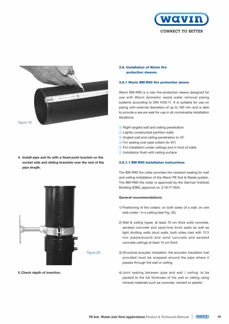