Waves, Polarization, and Coherence - Biophotonics Labbiophotonics.gist.ac.kr/Course...
27
2015-10-14 1 Waves, Polarization, and Coherence Lecture 6 Biophotonics Jae Gwan Kim [email protected] , X 2220 School of Information and Communication Engineering Gwangju Institute of Sciences and Technology Outline Models of Light Light as an Electromagnetic Wave Polarization of Light – Reflection and Refraction – Wave Propagation through Anisotropic Media Interference and Coherence of Light
Transcript of Waves, Polarization, and Coherence - Biophotonics Labbiophotonics.gist.ac.kr/Course...

2015-10-14
1
Waves,Polarization,andCoherence
Lecture6
Biophotonics
JaeGwan Kim
[email protected] ,X2220
SchoolofInformationandCommunicationEngineering
Gwangju InstituteofSciencesandTechnology
Outline
ModelsofLight
LightasanElectromagneticWave
PolarizationofLight
– ReflectionandRefraction– WavePropagationthroughAnisotropicMedia
InterferenceandCoherenceofLight

2015-10-14
2
)cos()(2cos),(
tkzAt
zAtzE
Electromagnetic wave varies in space and time
δ is the phase constant
Electric field can be written as a :
scalar
or a vector )cos(),(
tkzAtzE
The direction of the electric field vector (which is not the same as the direction of light propagation!) is called thepolarization direction.
]Re[)cos( ixex Please remember:
LightasanElectromagneticWave
PolarizationofMonochromaticPlaneWaves
ConsideraplaneEMwavepropagatinginthezdirection→ willlieinthe(x,y)plane
E
)(Re),( kztjeAtzE
wherethecomplexenvelope:
yeAxeAyExEA yxj
yj
xyx ˆˆ
tAE xx cos
tAE yy coswhere
xy
Forsomez=constantthecomponentsofthefieldwillvaryas:

2015-10-14
3
1. In phase ,0
)cos(
cos
tAE
tAE
yy
xx
tAE
tAE
yy
xx
cos
cos x
x
yy E
A
AE
x
y
xA
yA
0
x
y
xA
yA
Linear equation
LinearPolarizedLight
2. , 90 degree out of phase 2
)cos(
cos
tAE
tAE
yy
xx
tAE
tAE
yy
xx
sin
cos 1
2
2
2
2
y
y
x
x
A
E
A
E
x
xA
yA
2
E
y
xA
yA
E
2
x
xE x
y
E
y
A A
yx EE For particular case of
Standard elliptical equation
CircularPolarizedLight
Left hand polarization Right hand polarization

2015-10-14
4
3. General cases
)cos(
cos
tAE
tAE
yy
xx 22
2
2
2
sincos2
yx
yx
y
y
x
x
AA
EE
A
E
A
E
x
xA
yAy
xA
yAy
x
xA
yA y
x
xA
yA y
x
General elliptical equation
EllipticalPolarizedLight
LinearPolarizationin3DMovies
The glasses allow only one of the images into each eye.The two images are separated for each eye creating depth
Twosynchronizedprojectorsprojecttwoimagesonthescreen,eachwithadifferentpolarization(theimagesareprojectedthroughlinearpolarizers)

2015-10-14
5
ImportanceofPolarization
Polarizationplaysanimportantroleintheinteractionoflightwithmatter:
Theamountoflightreflectedattheboundarybetweentwomaterialsdependsonthepolarizationoftheincidentwave.
Theamountoflightabsorbedbycertainmaterialsispolarizationdependent
Lightscatteringfrommatterisgenerallypolarizationdependent
Therefractiveindexofanisotropicmaterialsdependsonthepolarization
Opticallyactivematerialshavethenaturalabilitytorotatethepolarizationplaneoflinearlypolarizedlight.
Thesepolarizationphenomenaareusedforbuildingimportantpolarizationdevices.
PolarizingFilter
• Apolarizingfiltercutsdownthereflections(top)andmadeitpossibletoseethephotographerthroughtheglassatroughlyBrewster'sangle althoughreflectionsoffthebackwindowofthecararenotcutbecausetheyareless‐stronglypolarized,accordingtotheFresnelequations

2015-10-14
6
FresnelEquations
• deducedbyAugustin‐JeanFresnel,describethebehavioroflightwhenmovingbetweenmediaofdifferingrefractiveindices.ThereflectionoflightthattheequationspredictisknownasFresnelreflection.
svs ppolarization
n1 n2
x
xx
y
y
y
k1
k3 k2
θi
θrθt
Reflectedwave
perpendicular polarization(or TE or s polarization, “s” easier to remember if we thinkof the arrow “slapping” the mirror)
parallel polarization(or TM or p polarization, “p” easier to remember if we thinkof the arrow “poking” the mirror)
mirror mirror
By solving a boundary value problem for the electromagnetic wave at the interface one can derive the Fresnel equations. This set of 4 equations gives the amounts of perpendicular and parallel polarized that reflected and transmitted at the interface.
Plane of Incidence
2015-10-14
7
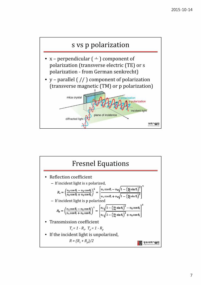
s vs ppolarization
• x– perpendicular( ┴)componentofpolarization(transverseelectric(TE)orspolarization‐ fromGermansenkrecht)
• y– parallel(//)componentofpolarization(transversemagnetic(TM)orppolarization)
FresnelEquations
• Reflectioncoefficient– Ifincidentlightisspolarized,
– Ifincidentlightisppolarized
• TransmissioncoefficientTs =1‐ Rs,Tp=1‐ Rp
• Iftheincidentlightisunpolarized,R=(Rs +Rp)/2

2015-10-14
8
FresnelEquations
• TheamplitudesofreflectioncoefficientRandtransmissioncoefficientTare
R= and
whererandtaretheratioofthereflected/transmittedwave’scomplexelectricfieldamplitudetothatoftheincidentwave
Brewster’sAngle
• Anangleofincidenceatwhichlightwithaparticularpolarizationisperfectlytransmittedthroughatransparentdielectricsurface,withnoreflection.
• Whenunpolarized lightisincidentatthisangle,thelightthatisreflectedfromthesurfaceisthereforeperfectlypolarized
polarizer

2015-10-14
9
Brewster’sAngle,CriticalAnglen1< n2 – external reflection(ex: reflection from air to glass)
Brewster’s angle – the incidence angleat which the parallel polarized waveis not reflected
1
21tann
nB
n1> n2 – internal reflection(ex: reflection from glass to air)
Critical angle – the incidence anglefor which the refraction angle is 900
(for θ>θc all the incident light is totally reflected)
1
21sinn
nc
Brewster,CriticalAngleApplic.
Forθ>θc→totalinternalreflection→usedforlightpropagationinopticalfibers
θB
A Brewster window transmits TM (parallel) polarized light with no reflection loss (used in lasers cavities)
Polarizer-a device which converts an unpolarizedbeam into a beam with single polarization state
If unpolarized light is incident on a surfaceat Brewster angle, the reflected light is linearly polarized with the electric vector perpendicularto the plane of incidence (the parallel componentis not reflected) → polarization by selective reflection
Partiallyp‐polarizeds‐polarized

2015-10-14
10
• Linerpolarizer– Absorptivepolarizer:theunwantedpolarizationstatesareabsorbedbythedevice
• Crystals:tourmaline,herapathite• PVA plasticwithaniodinedopingisstretchedduringthemanufacturingprocess
• Wire‐gridpolarizer:– Paralleltothewireisreflectedwhiletheperpendiculartothewireistransmitted
– Theseparationdistancebetweenthewiresmustbelessthanthewavelength oftheradiation,andthewirewidthshouldbeasmallfractionofthisdistance.
– Thismeansthatwire‐gridpolarizersaregenerallyonlyusedfor microwaves andforfar‐ andmid‐infrared light.
Polarizer
Polarizer
• Linerpolarizer– Beam‐splittingpolarizer:theunpolarized beamissplitintotwobeamswithoppositepolarizationstates
• Polarizationbyreflection
• Birefringent polarizer• Thinfilmpolarizer:glasssubstratesonwhichaspecialopticalcoatingisappliedcausinganinterferenceeffects

2015-10-14
11
Birefringence
• Ananisotropic crystalexhibitsdifferentrefractiveindicesfordifferentpolarizationcomponentsofthelight→whenlightrefractsatthesurfaceofananisotropiccrystal(quartzorcalcite),thetwopolarizationsrefractsatdifferentangles,beingspatiallyseparated(birefringence ordoublerefraction).
• Usually,twocementedprismsmadeofanisotropic(uniaxial)crystalsindifferentorientationsareusedtoobtainpolarizedfromunpolarized light.
OpticalAxis
• An opticalaxis isalinealongwhichthereissomedegreeof rotationalsymmetry inan opticalsystemsuchasa cameralens or microscope.
• Foran opticalfiber,theopticalaxisisalongthecenterofthe fibercore,andisalsoknownasthefiberaxis.

2015-10-14
12
OpticAxisofaCrystal
• It isthedirectioninwhicha ray oftransmittedlightsuffersno birefringence
• Uniaxialcrystals:thehexagonal,tetragonal,andtrigonal crystalsystemshaveoneopticaxis
• Biaxialcrystals:orthorhombic,monoclinic,andtriclinichavetwoopticaxes
• Ifthelightbeamisnotparalleltotheopticaxis,thenthebeamissplitintotworays(theordinaryandextraordinary)whenpassingthroughthecrystal.Theserayswillbemutuallyorthogonallypolarized.
CrystalStructures

2015-10-14
13
Ordinaryvs Extraordinary
• Ifunpolarized lightentersthebirefringent materialatsome angleofincidence,– thecomponentoftheincidentradiationwhosepolarizationisperpendiculartothecrystalaxis(ordinaryray)willberefractedaccordingtothestandard lawofrefraction foramaterialofrefractiveindex no,
– theotherpolarizationcomponent,theso‐calledextraordinaryraywillrefractatadifferentangledeterminedbytheangleofincidence,theorientationoftheopticaxis,andthebirefringence
BirefringentPolarizer
Nicoleprism Glan‐Thomsonprism
Glan‐Foucaultprism Glan‐Taylorprism

2015-10-14
14
BirefringentPolarizer
Ordinaryrayoro‐ray
Extraordinaryrayore‐ray
WollastonPrism
Crystalaxis
Senarmont Prism
Rochon Prism
15~45o
Malus’law
• Whenaperfectpolarizerisplacedinapolarizedbeamoflight,theintensity,I,ofthelightthatpassesthroughisgivenby
WhereIo istheinitialintensityθi istheanglebetweenθ0andθ1

2015-10-14
15
Polarizer
• Circularpolarizer(polarizingfilter)– tocreatecircularlypolarizedlightoralternativelytoselectivelyabsorborpassclockwiseandcounter‐clockwisecircularlypolarizedlight
– Polarizingfiltersinphotography– 3DGlasses
A typical wave plate is made of anisotropic materials (birefringent crystal).
There is a phase delay between the two polarization components which “see” different refractive indices of the anisotropic material
The phase difference is given by:
where L is the length of the wave plate; n1, n2-the refractive indices correspondingto the two polarization components
Lnn )(2
1221
2
→ a half wavelength, Half wave plate
→ a quarter wavelength, Quarter wave plate
Wave plate (retarder)
WaveRatarder (Waveplate)

2015-10-14
16
The light remains linear polarized, but the polarization plane will be rotated at 2θ.
The polarization plane can be rotated by different angles if the half wave plate is rotated
)cos(
cos
originyy
xx
tAE
tAE
For linear polarized light (δorigin=0 or π), after passing a half wave plate:
)0or ()or (0 origintotal
linear polarization
HalfWavePlate
When do we need to use a half wave plate?
-in an experimental set-up when the plane of polarization of a laser beam needs to be rotated
- when the laser power needs to be attenuated, a wave plate and a polarizer can be used for this purpose
details, principle of operation & videos:http://www.newport.com/content/default.aspx?id=516
HalfWavePlate

2015-10-14
17
2
A quarter waveplate shifts the relative phase by .
What is the effect of a quarter waveplate on linear and circular polarized light?
PossibleExamQuestion
PossibleExamQuestion
2
A quarter wave plate converts a linear polarization into a circular polarization and vice-versa.
2
A quarter waveplate shifts the relative phase by .
What is the effect of a quarter waveplate on linear and circular polarized light?

2015-10-14
18
Outline
ModelsofLight
LightasanElectromagneticWave
PolarizationofLight
– ReflectionandRefraction– WavePropagationthroughAnisotropicMedia
InterferenceandCoherenceofLight
Interference

2015-10-14
19
Interference
The phenomenon by which (electromagnetic) waves interact with one another
Interference is the result of the superposition principle:
i
i trEtrE ),(),(
Consider two fields (most general case:different directions, different frequencies) :
)cos(),( 111011
trkEtrE
)cos(),( 222022
trkEtrE
Interference occurs when the two fields are overlappedspatially and temporally
Intensity(Irradiance:energy/area/time)
),( trE
• We do not actually measure the electric field .
• We measure the intensity of the light.
• Add intensities is not always the same as adding the electric fields.
for coherent light.
We only add intensities when the light is incoherent.
2),(~),( trEtrI
2
2121 ),(),(),(),( trEtrEtrItrI

2015-10-14
20
Interference
The measurable quantity is the intensity!
where < > stands for time average
////////),( 21212
22
1 EEEEEEtrI
I1 I2 I12Interference term
221 /),(),(/),( trEtrEtrI
α
1E
2E
cos2121 EEEE
dot product
2021
forEE
No interference for perpendicular polarizations !Maximum interference for parallel polarizations
Interference
Assume parallel polarizations:
where
For simplicity, we’ll get rid of the time average < > and assume real fields
So,
)(011
111 tzkjeEE)(
022222 tzkjeEE
)(02
)(01
)(02
)(01
221
2 222111222111//// tzkjtzkjtzkjtzkj eEeEeEeEEEEI
cos2cos2 212102012
022
01
)(0201
202
201
212121212121
IIIIEEEE
eeEEEE tzkkjtzkkj
212121 tzkkcos2 2121 IIIII

2015-10-14
21
Interference
212121 tzkkcos2 2121 IIIII
+
inphase
...2,1,02 nforn
+
...2,1,0)12( nforn
outofphase
Constructiveinterference Destructiveinterference
+
Nointerference
...2,1,02
)12( nforn
Wave splitting
Wave combina-
tionLight source
Introduction of phase difference
Introduction of phase
difference
Key elements in an interferometer
• Light source
• Element for splitting the light into two partial waves
• Different propagation paths where the partial waves undergo different phase contributions
• Element for superposing the partial waves
• Detector for observation of the interference
Interferometer
2015-10-14
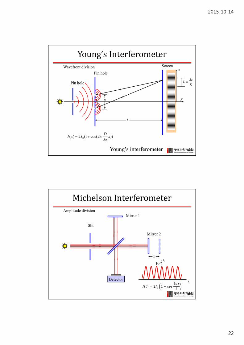
22
y
Wavefront division
))2cos(1(2)( 0 xz
DIxI
D
z
x
Young’s interferometer
Pin hole
Pin hole
Screen
D
zL
Young’sInterferometer
Amplitude division
Detector
Mirror 1
Mirror 2
Slit
x
2/11I
t
MichelsonInterferometer
2 14

2015-10-14
23
Coherence
21 III no interference → the beams are incoherent
→ the beams are coherentIf θ=0, π… and I1 = I2, I = 4I1
cos)(2 2121 IIIII
1)(0
→ the beams are partially coherent
cos2 2121 IIIII
Degree of coherence
coherentincoherent
Incoherence
21 kk
This can occur if, for ex:
21 frequencies drastically different or many waves of different frequencies( temporal incoherence )
21 kk k vectors drastically different or many waves originating from different locations ( spatial incoherence )
)( 11 tzkje
)( 22 tzkje
21 No interference!Incoherent source!
21 III no interference → the beams are incoherent

2015-10-14
24
Coherence‐spatialvs temporal
Temporal coherence – means a strong correlation (fixed phase relationship) betweenthe electric fields at one location but different times.
Temporal coherence tells us how monochromatic a source is!
two fields oscillating at the same frequency butdelayed with each other → perfectly correlated
Spatial coherence – means a strong correlation (fixed phase relationship) betweenthe electric fields arriving at the same time but different locations.
For ex, within a cross section of a beam from a laser with diffraction limited beam quality,the electric fields at different positions oscillate in a correlated way.
Spatial coherence tells us how collimated (non-divergent ) a source is!
Coherence‐spatialvstemporal
https://youtu.be/paEe‐EZ2eXc

2015-10-14
25
)4
cos1(2)( 0 x
ItI
Mirror 2
Mirror 1
Slit
x
Detector
Temporal coherence
Spatial coherence
yD
z
x
))2cos(1(2)( 0 xz
DIxI
SpatialandTemporalCoherence
Lc: coherence length, Temporal coherence is determined by the emission spectrum of the light source
cL
x
I cL
x
I
Wavelength (nm)
I
Wavelength (nm)
I
Fourier Transform.
EmissionSpectrum,TemporalCoherence

2015-10-14
26
QuantifyingCoherence
1cCoherence time - the source bandwidth
A narrow linewidth means high temporal coherence and long coherence length !
Coherence length
20~cc cL c – the speed of light, Δλ: source spectral width
Coherence Time

2015-10-14
27
References
B.E.A. Saleh, M.C. Teich, “Fundamentals of Photonics”
M. Born, E. Wolf, “Principles of Optics: Electromagnetic Theory of Propagation, Interference and Diffraction of Light”