WaveRider - bio-medical.combio-medical.com/media/support/waverdrpro.pdfSelect a MIDI Device...
154
WaveRider Operating Manual www.MindPeak.com Copyright 1997-2004 Jonathan Purcell All Rights Reserved MindPeak (formerly WaveAccess) P.O. Box 2928 Petaluma, CA 94953 USA +707-778-0370 tel +707-778-8693 fax [email protected] www.MindPeak.com
Transcript of WaveRider - bio-medical.combio-medical.com/media/support/waverdrpro.pdfSelect a MIDI Device...

WaveRiderOperating Manual
www.MindPeak.com
Copyright 1997-2004 Jonathan PurcellAll Rights Reserved
MindPeak(formerly WaveAccess)P.O. Box 2928Petaluma, CA 94953 USA+707-778-0370 tel+707-778-8693 [email protected]

WaveRider Operating Manual
2Copyright 1997-2004 Jonathan PurcellAll Rights Reserved
NOTICE:The WaveRider is an experimental musical instrument intended for musical performance andcomposition, education, and experimental computer interface applications. The WaveRideris not intended for any type of medical use in either a diagnostic or therapeutic capacity. Anyindividual or organization using the WaveRider in a medical capacity does so without theendorsement of MindPeak/WaveAccess.

WaveRider Operating Manual
3Copyright 1997-2004 Jonathan Purcell
All Rights Reserved
The only means of strengthening one's intellect is tomake up one's mind about nothing --to let the mind bea thoroughfare for all thoughts. Not a select party.JOHN KEATS 1795-1821
Absence of occupation is not rest,A mind quite vacant is a mind distress'd.
WILLIAM COWPER 1731-1800
My mind to me a kingdom is,Such present joys therein I find,That it excels all other blissThat earth affords or grows by kind.SIR EDWARD DYER 1700?-1758
From doubt to certainty is but a breath,A breath from unfaith's halting place to faith,This precious breath then do you cherish, forLife's sum is but a breath from birth to death
OMAR KHAYYAM
For many days , my brainWorked with a dim and undetermined senseOf unknown modes of beingWILLIAM WORDSWORTH 1770-1850
MOVING FORWARDThe deep parts of my life pour onward,as if the river shores were opening out.
It seems that things are more like me now,that I can see farther into paintings.
I feel closer to what language can't reach.With my senses, as with birds, I climbinto the windy heaven, out of the oak,
and in the ponds broken off from the skymy feeling sinks, as if standing on fishes.
RAINER MARIA RILKE 1875-1926 (trans. R. Bly)

WaveRider Operating Manual
4Copyright 1997-2004 Jonathan PurcellAll Rights Reserved
TABLE OF CONTENTS
OPERATING MANUAL ...................................................................................................................................... 1
TABLE OF CONTENTS.................................................................................................................................. 4THE SIGNIFICANCE OF BRAINWAVES AND CONSCIOUSNESS .......................................................... 6HOW TO USE THIS MANUAL...................................................................................................................... 7
QUICK START.................................................................................................................................................... 9
Hardware Installation ................................................................................................................................ 10Hardware Installation Notes ...................................................................................................................... 11Software Installation .................................................................................................................................. 12
USING THE WAVERIDER FOR THE FIRST TIME.................................................................................................. 12Set up the MIDI Device .............................................................................................................................. 12Set up the Comm Port ................................................................................................................................ 13
ONE PAGE OPERATIONAL OVERVIEW .............................................................................................................. 14CONNECTING BRAINWAVE ELECTRODES ......................................................................................................... 16
Tips for Electrode Use................................................................................................................................ 18Conditions Necessary for Good Electrode Contact ................................................................................... 18Notes on Attaching Brainwave Electrodes ................................................................................................. 19
CARING FOR ELECTRODES ............................................................................................................................... 21ELECTRODE PLACEMENT ................................................................................................................................. 23
LEARNING THE HEART, GSR, BRAIN AND MUSCLE MODES............................................................ 25
HEART ........................................................................................................................................................... 26GSR................................................................................................................................................................. 28BRAIN ............................................................................................................................................................ 30MUSCLE ........................................................................................................................................................ 32
KEY CONCEPTS.............................................................................................................................................. 35
CHANNELS ....................................................................................................................................................... 36
USE CATEGORIES ....................................................................................................................................... 36FILE CREATION........................................................................................................................................... 37
Configuration Files .................................................................................................................................... 37Archive Files .............................................................................................................................................. 37ASCII FILE OUTPUT (Exporting to a spreadsheet).................................................................................. 38
WINDOWS..................................................................................................................................................... 39Strip Chart.................................................................................................................................................. 40Fast Bars and Slow Bars............................................................................................................................ 42Spectrogram ............................................................................................................................................... 44GSR Graph................................................................................................................................................. 46
MIDI ............................................................................................................................................................... 48FFTS, DIGITAL FILTERS AND SIGNAL PROCESSING .......................................................................... 51
MINDGAMES: WAVERIDER LESSON PLANS......................................................................................... 53
INTRODUCTION ................................................................................................................................................ 54THE BODY: GSR, HEART & MUSCLE ............................................................................................................. 56
GSR ............................................................................................................................................................ 56PLAYING WITH THE HEART RATE......................................................................................................... 62MUSCLE .................................................................................................................................................... 66
RELAX ........................................................................................................................................................... 71PER CENT ALPHA .................................................................................................................................... 72

WaveRider Operating Manual
5Copyright 1997-2004 Jonathan Purcell
All Rights Reserved
PER CENT HI-ALPHA .............................................................................................................................. 76ALPHA AMPLITUDE ................................................................................................................................ 80GSR / % ALPHA ........................................................................................................................................ 84
ALPHA/THETA............................................................................................................................................. 88ALPHA/THETA WITH 2 TONES ............................................................................................................... 88ALPHA/THETA FOR 2 CHANNELS ......................................................................................................... 92
FOCUS ........................................................................................................................................................... 95BETA/THETA............................................................................................................................................. 96SMR/ THETA............................................................................................................................................ 100SMR/THETA FOR 2 CHANNELS ............................................................................................................ 108BETA/THETA FOR 2 CHANNELS .......................................................................................................... 110
ASSESSMENT............................................................................................................................................. 112BRAIN REFLECTOR ............................................................................................................................... 112CHECKER ............................................................................................................................................... 114
JUST FOR FUN............................................................................................................................................ 116BLUES ENSEMBLE................................................................................................................................. 116
PROGRAMMING WAVEWARE ................................................................................................................. 119
THE GENERAL GRAPHICS AND THE MIDI OPTIONS DIALOG BOXES .......................................... 120MIDI OPTIONS DIALOG BOX ............................................................................................................... 123GENERAL GRAPHICS OPTIONS DIALOG BOX................................................................................... 125POWER IN PASSBAND........................................................................................................................... 128RATIO OF POWER IN PASSBAND ........................................................................................................ 130DIGITAL FILTER ................................................................................................................................... 132RATIO OF TWO FILTERS....................................................................................................................... 134REWARD/SUPPRESS RATIO.................................................................................................................. 136REWARD/SUPPRESS.............................................................................................................................. 138DOMINANT FREQUENCY ..................................................................................................................... 140COHERENCE .......................................................................................................................................... 142HEART RATE........................................................................................................................................... 144GSR .......................................................................................................................................................... 146PEAK TO PEAK AMPLITUDE................................................................................................................ 148
NEUROSCIENCE: THE GENERATION OF BRAINWAVES.................................................................. 150
THE AUTONOMIC NERVOUS SYSTEM ................................................................................................ 150THE BRAIN.............................................................................................................................................. 151BRAINWAVE GENERATION .................................................................................................................. 153
APPENDICES.................................................................................................................................................. 154
WHAT IS DDE AND THE DDE SDK? ...................................................................................................... 154
WaveRider Operating Manual
6Copyright 1997-2004 Jonathan PurcellAll Rights Reserved
THE SIGNIFICANCE OF BRAINWAVES AND CONSCIOUSNESS
What is observed as consciousness is the interaction of many complex biological systems.These systems can be viewed from a variety of vantage points. There are biochemical,anatomical, psychological, and electrophysiological explanations of the workings of themind.
Brainwave states are another perspective on the mind, albeit an imperfect one. They reflect asmall portion of the activity of the brain, and only on a very gross level. The events observedas brainwaves are epi-phenomena of more fundamental processes. They contain though,important information about ones's mental state. Brainwave rhythms reflect primarily theworking of the thalamus and limbic system. Brainwave states correlate with mental states ofconcentration, relaxed attentiveness, and deep relaxation.
By observing sensations while producing specific brainwave states, one can learn how toproduce those states more effectively and in a variety of situations. Stress, relaxation,concentration, free association of thought, and the ability to stay ‘connected’ with anotherperson, are better managed when one has greater control over their state of mind. Bypracticing the production of specific brainwave states, while observing one’s state of mindand other sensations, one can become skilled at intentionally producing specific mental statesin real life situations.
Our will alone can change our state of mind.

WaveRider Operating Manual
7Copyright 1997-2004 Jonathan Purcell
All Rights Reserved
HOW TO USE THIS MANUALThe information in this manual is arranged in order of importance for a new user.
All users should completely use and understand the QUICK START Section. Quick Startcovers installation of hardware and software, use and care of electrodes, and a briefoperational overview. Of particular importance is the section on attaching andtroubleshooting electrode contact, as this represents the number one issue of first time users.
LEARNING THE HEART,GSR, BRAIN AND MUSCLE MODES is directed at individualswith no experience in using biological data acquisition equipment.
KEY CONCEPTS provides a useful overview of the functions of WaveWare Software.
MINDGAMES is a set of lesson plans. Each lesson corresponds to a configuration fileinstalled with WaveWare.
PROGRAMMING WAVEWARE describes how to program each of the MIDI Options andGeneral Graphics Options dialog boxes in WaveWare. This information is necessary to alterexisting configuration files and to author new ones.
NEUROSCIENCE is an extremely brief overview of the physiology of brainwave generation.Later sections cover more in depth topics and can be consulted as need and desire arises.

WaveRider Operating Manual
8Copyright 1997-2004 Jonathan PurcellAll Rights Reserved

WaveRider Operating Manual
9Copyright 1997-2004 Jonathan Purcell
All Rights Reserved
QUICK START

WaveRider Operating Manual
10Copyright 1997-2004 Jonathan PurcellAll Rights Reserved
Hardware Installation
WaveRider Pro
WaveRider jr.
Install a BatteryInstall a fresh 9-Volt battery (not included) in the battery compartment.
Connect Serial CableThe WaveRider includes a 9 pin male to female serial cable.
1. Connect the female end of the serial cable to a serial port on the back of the computer.2. Connect the male end of the serial cable to the connector on the back of theWaveRider.

WaveRider Operating Manual
11Copyright 1997-2004 Jonathan Purcell
All Rights Reserved
Hardware Installation Notes
Batteries
NEVER connect theWaveRider to AC power lines using a voltage converter. Doing socould compromise the safety of the user.
Disposable BatteriesRecommended batteries include high quality 9-volt alkaline and lithium cells.
Rechargeable BatteriesRecommended batteries include 9-volt Nickel Metal Hydride (NiMH) cells. NickelCadmium (NiCad) are not recommended. Some people have used 12 volt gel cell motorcyclebatteries that sit outside the case of the WaveRider and can be recharged periodically with acar battery type charger.
Serial Port ConnectionYou may need to use a 9-25 pin adapter, if your available serial port has 25 pins.If the cable is difficult to attach, make sure that the shape of the plug matches the connector.
Using a USB to Serial Port ConverterMany newer computers have a USB port but do not have a serial port. TheWaveRider will work with most USB to serial port converters if the serial converter isassigned to the proper comm port. WaveWare can connect to comm ports 1, 2, 3, or 4. MostUSB to serial port converters allow the serial port to be assigned to a user selectable commport. The default comm port setting may be to a comm port other than 1, 2, 3, or 4.Changethe assigned port settings in device manager.

WaveRider Operating Manual
12Copyright 1997-2004 Jonathan PurcellAll Rights Reserved
Software Installation1. Exit all applications.2. Insert the WaveWare diskette in a 3.5 inch floppy disk drive.3. Select run from the Task Bar.4. Type a:\setup.exe or use the browse button to select setup.exe.5. Press the enter key on the keyboard.6. Follow the directions on the screen for installation.7. When installation is complete drag the WaveWare icon onto your desktop.
Using the WaveRider for the First Time1. Launch the WaveWare application.2. WaveWare will prompt you to select a MIDI Device.3. Select a MIDI Device according to the directions below.4. Turn the WaveRider on by clicking the WaveWare ‘on’ button with your mouse or by
typing ‘ctrl’ + ‘o’ on your keyboard.5. WaveWare will prompt you to select a comm (serial) port.6. Select a comm port according to the directions below.
The comm port is properly installed when the red light on the WaveRider will come on andstay on when the ‘on’ button in WaveWare is checked.
Set up the MIDI Device
The first time you launch the WaveWare application after installation you will be promptedto select a MIDI device. In subsequent launches set the MIDI Device in WaveWare byselecting Change MIDI Device in the SOUND MENU.
SOUNDBLASTER TYPE DRIVER If you have a SoundBlaster or a SoundBlaster compatible sound card, you will be presentedwith the following choices (or some variation):
MIDI MapperMicrosoft GS WaveTable SW synthMIDI-OUT
SoundBlaster Connected to Speakers: Most Common SetupIf you are using your WaveRider with a SoundBlaster connected to a pair of speakers, chooseMicrosoft GS WaveTable SW synth or any other synth type device listed (but not MIDI-outor MIDI-mapper).SoundBlaster (or MIDI card) Connected to External Synthesizer
If you are using an external synthesizer connected to your sound-card or MIDI-cardyou will need to select either MIDI OUT or MIDI MAPPER.
This type of sound card allows you to send MIDI data to either the internalsynthesizer (in the sound card) or to an external synthesizer, (but not both simultaneously).

WaveRider Operating Manual
13Copyright 1997-2004 Jonathan Purcell
All Rights Reserved
MPU-401 TYPE DRIVERIf your sound card uses an MPU-401 type driver, it will send data to the internal synthesizerand to the MIDI outs simultaneously.
The preceding instructions assume that your sound-card is properly installed for Windows. Ifyour sound card is not properly installed, contact your sound card manufacturer to obtain theappropriate drivers and advice.
Set up the Comm PortThe first time you turn on the WaveRider using WaveWare you will be prompted to select aserial (comm) port for the WaveRider. In subsequent launches set the comm port inWaveWare by selecting CHANGE COMM PORT in the OPTIONS MENU. Make sure thatthe comm port that you choose matches the comm port towhich your WaveRider isconnected. In addition, make sure that the comm port has no interrupt (IRQ) conflicts withother devices.
Trouble Shooting Comm Port Setup1. A fax/modem and WaveRider may share an IRQ if they have separate addresses
(comm ports) and are not used simultaneously. (If your fax/modem software has abackground fax reception option you may need to disable the background reception ifthe fax/modem shares an IRQ with the WaveRider).
2. If you turn your WaveRider on and the red light comes on momentarily, you probablyhave an IRQ conflict. You will need to find non-conflicting settings for the devices onyour computer. The best way to start is to make a complete list of all the devices onyour computer with their addresses and IRQs. Look for any conflicts. If you are acomputer novice you may need the help of a computer expert to properly configureyour devices.

WaveRider Operating Manual
14Copyright 1997-2004 Jonathan PurcellAll Rights Reserved
One Page Operational OverviewDouble clicking on any window brings up that window’s dialog box.
Biological channels are A & B (WaveRider jr.), and A, B, C, & D (WaveRider Pro).
To raise and lower the gain (amplification) on a specific channel use the arrow keys on thekeyboard when a strip chart (brain, muscle or heart) for that channel has the input focus. Theactive window is the window with the input focus (the active window has a title bar of adifferent color).
Do not try to play with biological signals (especially brainwaves) unless you are sure that youhave a good connection and a solid reliable signal.
LOAD CONFIGURATION in the FILE menu allows you to select a new configuration file.
SAVE CONFIGURATION in the FILE menu saves the setup that you have on your screen.If you give the configuration the name ‘waveware.cfg’ it will be the default configuration thatwill be loaded when WaveWare is launched.
NEW ARCHIVE in the FILE menu allows you to save biological data.
OPEN ARCHIVE in the FILE menu allows you to replay stored biological data.
The use categories of configuration and archive files must match.
Ctrl + O Turns the WaveRider on and off.Ctrl + F Freezes and unfreezes the display.Ctrl + R Starts recording in record mode.F1 Starts helpF3 Mutes the soundF4 Unmutes the sound
Low Battery Is indicated by the outside of the battery slider becoming red.

WaveRider Operating Manual
15Copyright 1997-2004 Jonathan Purcell
All Rights Reserved

WaveRider Operating Manual
16Copyright 1997-2004 Jonathan PurcellAll Rights Reserved
Connecting Brainwave Electrodes
Put a small amount of skin preparation gel (NuPrep) on a finger.
Rub the skin preparation gel into the earlobes and the electrode site(s) on the head.The skin preparation abrades the top dead layer of the skin making for lower skin impedanceand a better connection.
Wipe off any excess skin preparation with a tissue.
Put a dab of conductive paste (Ten20) in each head electrode and in each cup of both earelectrodes.

WaveRider Operating Manual
17Copyright 1997-2004 Jonathan Purcell
All Rights Reserved
Attach an earclip to each earlobe. Make sure that each ear clip makes good contact with its’ear lobe. You may need to gently re-bend the ear clips if they become bent, or no longer fullyclose.
Use your fingers to move hair out of the way of the head electrode site. Place the headelectrode firmly on the electrode site making sure that the rim of the electrde sits flat on thehead with a minimum of hair beneath it. To achieve the best connection you may need torotate the electrode between your thumb and forefinger while keeping the rim of the electrodeflat on the head. Place the electrode wires so that they are not pulled during the session.

WaveRider Operating Manual
18Copyright 1997-2004 Jonathan PurcellAll Rights Reserved
Tips for Electrode Use• If you adjust the electrodes, wait for the signal to settle.• Don't play with the wires while using the WaveRider.• A poor connection may get better if the electrodes remains on the head for a few
minutes• A good electrode connection may go bad.
If this happens try the following approaches listed in order of increasing effort:1. adjusting the electrode and ear clips and waiting for the signal to settle,2. wiping the paste off and re-applying the electrode and ear clips,3. wiping the paste off with a warm wet washcloth, cleaning the electrodes andstarting over.
Conditions Necessary for Good Electrode ContactBefore collecting brainwaves make sure:
• The signal indicates a good quality connection. (See below).• Electrodes were thoroughly cleaned with hot water and cotton swabs immediately
after previous use.• Skin is clean and free of dirt, sweat, oils and cosmetics.• Electrode site and ears are prepped with NU-Prep and/or alcohol.• The head and ear electrodes are filled with paste and well adhered to the sensor site.• The rim of the electrode is flat on the head.• The electrode lead wire plug is fully seated in the WaveRider jack.• All hair is moved out of the way of the electrodes.• The lead wires are not tangled.

WaveRider Operating Manual
19Copyright 1997-2004 Jonathan Purcell
All Rights Reserved
Notes on Attaching Brainwave Electrodes
Attaching electrodes is more of an art than a science. It is not unusual for first time users ofelectrodes to have difficulty establishing a good brainwave electrode contact.
Electrode contact is extremely important. If electrodes do not make a good contact theWaveRider will display random environmental noise rather than electrophysiological data. Ifsignals resembling brainwaves are displayed that appear identical whether or not theelectrodes are attached to the body, this indicates a poor connection.
A bad signal may be caused by a poor electrode connection and/or improper leadwireplacement. Electrode contact and leadwire placement are the most important aspects of noisecancellation.
Sources of poor electrode contact include:• Poorly attached electrodes,• High skin impedance (due to skin that is oily, dirty or that has a lot of dead skin cells),• Dirty or oxidized electrodes. (See below for information on cleaning electrodes).
Sources of improper leadwire placement include:• Long lead wires,• Lead wires being moved,• Lead wires that pass by a source of electrical noise such as a computer monitor.
How to Determine Electrode Contact QualityWhether a good signal has been achieved is determined by viewing the strip chart of thechannel to which the electrodes are attached. Poor electrode contact can result in the stripchart displaying two different conditions. In the first condition the signal displaysinsufficient amplitude ( i.e. vertical movement) under appropriate amplification (usuallyrange 7 for brainwaves). The signal should typically occupy at least 30% of the verticalheight of the strip chart window under appropriate amplification. In the second condition asignal with substantial amplitude is displayed, but the signal displays environmental noiserather than a biological signal. The environmental noise will usually be interference from 50or 60 hertz power lines, but can also be caused other electronic devices such as computermonitors.

WaveRider Operating Manual
20Copyright 1997-2004 Jonathan PurcellAll Rights Reserved
Insufficient amplitude:
Environmental noise:
Good signal:
The WaveRider has user selectable hardware amplification. The amplification is changed byraising and lowering the up and down arrow keys on the keyboard when a strip chart windowhas the input focus. The active window is the window with the input focus.
If the amplification is too high, the signal will crash into the top and bottom rails of theamplifier. This will saturate the amplifier and will cause large parts of the signal to not trulyreflect the biological signal being observed.
There is a notch filter that blocks out the power distribution frequency. In countries that use60 HZ power this is a 60 Hz filter. In countries that use 50 Hz power this is a 50 Hz filter.There is a conversion kit available for individuals who operate between countries withdifferent power distribution frequencies. Since Japan uses both 50 & 60 Hz a special versionis available that filters out both 50 & 60 Hz.

WaveRider Operating Manual
21Copyright 1997-2004 Jonathan Purcell
All Rights Reserved
Caring For Electrodes
Ear and head electrodes should be carefully cleaned immediately after every use.
Use hot running water and cotton swabs to clean the conductive paste from the head and earelectrodes.
Warm and wet each head and ear electrode under hot running water while cleaning theconductive paste with a cotton swab.
Be careful not to twist the ear clips out of position. The ear clips should close completely andthe two halves should remain parallel.

WaveRider Operating Manual
22Copyright 1997-2004 Jonathan PurcellAll Rights Reserved
Brainwave electrodes can become oxidized from failure to clean after use, age, or exposure toair. Oxidation can be visible or invisible. Minor oxidation can be remedied by cleaningelectrodes with alcohol, or by dipping in a silver cleaning solution available at most drugstores.

WaveRider Operating Manual
23Copyright 1997-2004 Jonathan Purcell
All Rights Reserved
Electrode PlacementThere is a standard pattern for placing electrodes on the scalp for the measurement ofbrainwaves. This is known as the 10-20 system. Each electrode site has a name composed ofa letter and a sub-script. Each letter (with the exception of C which stands for center) refers tothe cerebral lobe over which the electrode is placed, i.e. T=temporal, P=parietal, O=occipital,F= frontal, Fp=pre-frontal. The odd-numbered subscripts are on the left side of the head, theeven numbered sub-scripts are on the right. The subscript z is on the center line. Generally anactive electrode is placed on one ear lobe and a reference electrode on the other earlobe.

WaveRider Operating Manual
24Copyright 1997-2004 Jonathan PurcellAll Rights Reserved

WaveRider Operating Manual
25Copyright 1997-2004 Jonathan Purcell
All Rights Reserved
LEARNING THE HEART, GSR, BRAIN AND MUSCLE MODES

WaveRider Operating Manual
26Copyright 1997-2004 Jonathan PurcellAll Rights Reserved
HEART
Use the Heart configuration to look and listen to your heart rate change.1. From the FILE menu choose LOAD CONFIGURATION.2. Select HEART.CFG.3. Connect the electrodes as in the diagram. Use the disposable electrodes and lead wires
provided.4. Turn the WaveRider on by clicking the ON button with your mouse or by using “Ctrl” +
“O”.5. The heart strip chart should have a clean signal if the electrodes are properly connected.
To learn how to modify the configuration refer to:• STRIP CHART in the WINDOWS Section of the Key Concepts Chapter of this
manual,• HEART RATE in the PROGRAMMING WAVEWARE section of this manual,• or double click on any of the windows to view and modify their properties.

WaveRider Operating Manual
27Copyright 1997-2004 Jonathan Purcell
All Rights Reserved
CHANNELS USED FOR HEART MODE VARY BETWEEN MODELS AND MAYDIFFER FROM WHAT IS SHOWN

WaveRider Operating Manual
28Copyright 1997-2004 Jonathan PurcellAll Rights Reserved
GSR
Use the GSR configuration to learn how to modify your state of arousal.1. From the FILE menu choose LOAD CONFIGURATION.2. Select GSR.CFG.3. Connect the electrodes as in the diagram. Use the finger electrodes and lead wires
provided. Use no electrode gel or paste.4. Turn the WaveRider on by clicking the ON button with your mouse or by using “Ctrl” +
“o”.5. The GSR moves relatively slowly. Try taking deep breaths or thinking about your debts
or ex-lover.
To learn how to modify the configuration refer to:• GSR GRAPH in the WINDOWS Section of the KEY CONCEPTS CHAPTER of this
manual,• GSR in the PROGRAMMING WAVEWARE section of this manual,• or double click on any of the windows to view and modify their properties

WaveRider Operating Manual
29Copyright 1997-2004 Jonathan Purcell
All Rights Reserved

WaveRider Operating Manual
30Copyright 1997-2004 Jonathan PurcellAll Rights Reserved
BRAIN
Use the ALFAKOTO configuration to use your brainwaves to relax.1. From the FILE menu choose LOAD CONFIGURATION.2. Select ALFAKOTO.CFG.3. Connect the electrodes as in the diagram. Use the cup electrodes supplied and the ten-
20 paste. Make sure that the skin is clean and you have a good contact.4. Turn the WaveRider on by clicking the ON button with your mouse or by using “Ctrl” +
“o”.5. The brain strip chart should have a clean signal if the electrodes are properly connected.6. Close your eyes. Relax. Drop your shoulders. Make the note go up.
To learn how to modify the configuration refer to:• STRIP CHART in the WINDOWS Section of the KEY CONCEPTS CHAPTER of
this manual,• THE GENERAL GRAPHICS AND THE MIDI OPTIONS DIALOG BOXES in the
PROGRAMMING WAVEWARE section of this manual,• or double click on any of the windows to view and modify their properties

WaveRider Operating Manual
31Copyright 1997-2004 Jonathan Purcell
All Rights Reserved
WaveRider Operating Manual
32Copyright 1997-2004 Jonathan PurcellAll Rights Reserved
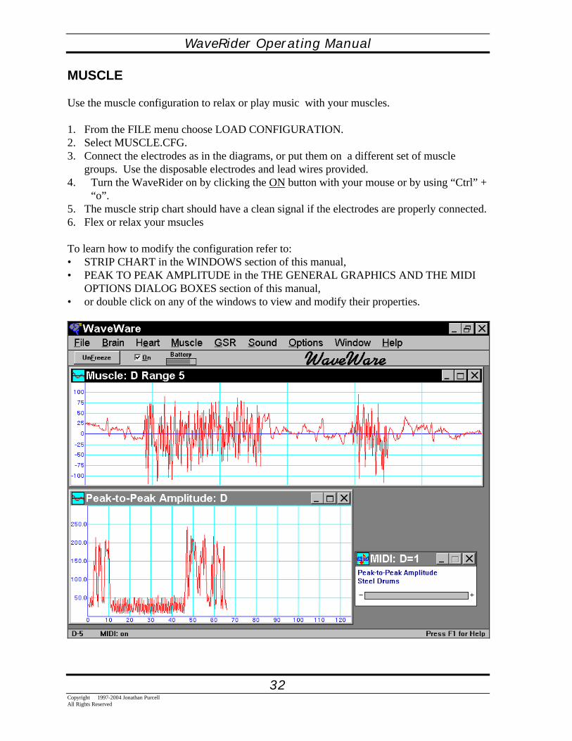
MUSCLE
Use the muscle configuration to relax or play music with your muscles.
1. From the FILE menu choose LOAD CONFIGURATION.2. Select MUSCLE.CFG.3. Connect the electrodes as in the diagrams, or put them on a different set of muscle
groups. Use the disposable electrodes and lead wires provided.4. Turn the WaveRider on by clicking the ON button with your mouse or by using “Ctrl” +
“o”.5. The muscle strip chart should have a clean signal if the electrodes are properly connected.6. Flex or relax your msucles
To learn how to modify the configuration refer to:• STRIP CHART in the WINDOWS section of this manual,• PEAK TO PEAK AMPLITUDE in the THE GENERAL GRAPHICS AND THE MIDI
OPTIONS DIALOG BOXES section of this manual,• or double click on any of the windows to view and modify their properties.

WaveRider Operating Manual
33Copyright 1997-2004 Jonathan Purcell
All Rights Reserved

WaveRider Operating Manual
34Copyright 1997-2004 Jonathan PurcellAll Rights Reserved

WaveRider Operating Manual
35Copyright 1997-2004 Jonathan Purcell
All Rights Reserved
KEY CONCEPTS

WaveRider Operating Manual
36Copyright 1997-2004 Jonathan PurcellAll Rights Reserved
CHANNELSWaveRider collects data on biological channels that are named by letters. Channels A & Bfor the WaveRider jr. and channels A, B, C & D for the WaveRider Pro.
WaveRider sends MIDI data out on numbered MIDI channels 1-16. It is important that theMIDI channels specified do not conflict with each other.
USE CATEGORIESWaveWare utilizes use categories to keep track of the type of data each biological channel isacquiring. Use category is an assignment that a channel is given when the first window thatmakes reference to it is opened. It is a somewhat invisible concept. The possible usecategories are BRAIN, HEART & MUSCLE. GSR is also a use category but GSR data canonly be acquired on the GSR channel.
Once a use category is assigned to a biological channel, WaveWare will not permit theassignment of another use category to that channel unless all windows that use that channelare closed. After all windows that reference that channel are closed, a new use category canbe assigned by opening a new window.
When an archive file is recorded each channel is assigned a use category. When aconfiguration file is created each channel is assigned a use category. In order to replay anarchive file through a configuration file, the use categories for each channel must match. If anarchive file and a configuration file are opened in which the use categories conflict, you willbe presented with a message that reads:
The file channels do not match the program setup
You will need to close the archive file and modify the configuration file so that there is noconflict with the archive file. It may be helpful to look at the ARCHIVE INFORMATION inthe FILE MENU to see what use categories the biological channels have assigned to them inthe archive file.

WaveRider Operating Manual
37Copyright 1997-2004 Jonathan Purcell
All Rights Reserved
FILE CREATIONWaveWare can create three types of files: configuration (.cfg) files, archive (.bio) files andascii (.txt) files.
Configuration FilesConfiguration files store the templated setups that you see on your screen when you look atWaveWare. They include the settings for each window as found in that windows dialog box.In addition they save global parameters such as colors, transform characteristics, and cycling.
SAVE CONFIGURATION in the FILE menu will save your configuration. If you use thename waveware.cfg for your configuration file it will become the default configuration filethat will be opened when WaveWare is launched.
LOAD CONFIGURATION opens a saved configuration file.
Archive FilesArchive files store unprocessed (raw time domain) biological data. These files can be of anylength and consume approximately 0.5 Megabyte/hour/channel in storage space.
To archive a live file.1. Turn on the WaveRider.2. Select NEW ARCHIVE from the FILE menu.3. Choose a name that will describe the file. It will be given a .bio extension.4. Use the Archive Options Dialog Box to select biological channels for recording, set the
Pre-Trigger Time (see below), and to write comments5. Click OK6. WaveWare will be in RECORD MODE and will display a RECORD button.7. When you click the RECORD BUTTON, WaveWare will begin to record.
Pre-Trigger TimePre-Trigger provides the ability to a record data a few seconds prior to the time the recordbutton is hit. This allows one to record immediately after an event of interest is observed, orafter the subject settles down.
Files can be played back and further processed in playback mode. Use OPEN ARCHIVEfrom the FILE menu to open recorded files. Archive files can be played back through anyconfiguration in which the use categories match.

WaveRider Operating Manual
38Copyright 1997-2004 Jonathan PurcellAll Rights Reserved
ASCII FILE OUTPUT (Exporting to a spreadsheet)Offline processed biological data may be exported to an ASCII (text) file. This data can beopened and further processed in a spread sheet or statistical analysis package. The streams ofprocessed data stored in the ASCII file will correspond to the General Graphics Windowspresent in the configuration file when the data is exported.
Directions for ASCII FILE OUTPUTASCII FILE OUTPUT will appear grayed out in the FILE menu unless both an archive file isopened and a configuration file is opened that has at least one non-GSR General GraphWindow.∗
1. Select ASCII FILE OUTPUT from the FILE menu.2. Create an 8 character name for your file at the prompt. This file will be given a .txt
extension.3. Hit OK
Description of ASCII FileThe ASCII file is comma delimited. Select the appropriate settings in your spread sheet tomake sure that the column breaks are put in the correct places.
The left most column is the time at which each processed data point was produced (inseconds). The General Graphics Window with the finest time resolution in the configurationfile used during the export of data, will define the time resolution of the ASCII file. Somedata streams may be calculated at a coarser resolution and not fill up every cell. Somecolumns of buffered data may not have data in the first few rows because, the buffered data isnot accurate until the first few readings have passed into the buffer.
Each General Graphics Window will create a column of numbers in the ASCII file. Eachcolumn will be given either the default title of the window produced by WaveWare or thename that was given to the General Graphics Window in the General Graphics OptionsDialog Box by the user.
∗ GSR General Graph may be output to ASCII but an additional non-GSR General Graphics window must beincluded in the configuration file.

WaveRider Operating Manual
39Copyright 1997-2004 Jonathan Purcell
All Rights Reserved
WINDOWSThe screens in WaveWare are composed of windows. Each window has a set of propertiesthat can be set in its' dialog box.
Any window’s dialog box may be accessed by double clicking on the middle of the windowwith your left mouse button. Do not click on the titlebar, since this will maximize thewindow.
What follows is a brief description of some of the windows and their associated dialog boxesin WaveWare .
The General Graphics and MIDI Output windows require more depth of explanation and aretreated in the PROGRAMMING WAVEWARE CHAPTER.

WaveRider Operating Manual
40Copyright 1997-2004 Jonathan PurcellAll Rights Reserved
Strip Chart
The STRIP CHART command in the BRAIN, HEART and MUSCLE menus opens awindow that displays the raw biological signals , or displays the same signals as they arelater replayed from an archive file. The strip chart display is especially helpful in monitoringthe electrode connections, and making sure that the range of the WaveRider channel is setproperly.
Double clicking on the Strip Chart window opens an Options box, which provides the abilityto change a number of settings affecting the strip chart display.
More than one channel may be displayed in the window; the default is to display twochannels, which could correspond to the left and right hemispheres of the brain.
By pressing the Up or Down arrow keys on the keyboard while a strip chart window has theinput focus, the Range of the WaveRider channels may be raised or lowered. If more thanone channel is displayed in one window, those channels become linked; the ranges of linkedchannels are always kept the same.
The strip chart window may be resized, minimized, or maximized.

WaveRider Operating Manual
41Copyright 1997-2004 Jonathan Purcell
All Rights Reserved
Strip Chart Options Dialog Box
CHANNELChoose among the WaveRider channels (or among the saved channels, if an archive file isbeing read); the chosen channels will be displayed in this strip chart window, one above theother. Some of the channel checkboxes may be grayed, indicating channels which have adifferent use category.
If multiple channels are displayed in one window, those channels become Linked; the rangesof linked channels are always kept the same.
MODEThree types of strip chart display may be selected from; choosing among these only affectsthe appearance of the strip chart window. The strip chart may be drawn using only the DOTSrepresenting the individual data points. Or the chart may be drawn using SOLID areas forgreater visibility. The default is to draw a continuous LINE representing the data.
SPACINGThe default x1 horizontal spacing uses one pixel per data point. If x2 or x3 are selected, eachpoint uses correspondingly more space in the window, making less data visible at one time.
GRIDBy default, a single axis is drawn horizontally across each strip chart to indicate the zeropoint of the signal. In addition, you may choose a grid indicating the amplitude of the signalin microvolts, with or without the numerical values along the left, or you may choose a totallyplain strip chart display with neither grid nor axis.
RANGEBy pressing the Up or Down arrow keys while a strip chart window has the input focus, theRange of the WaveRider channels may be raised or lowered. The range is not changeddirectly from the options dialog box.
ERASE AFTER EVERY SWEEPErases the previous signal trace before the new trace is drawn.

WaveRider Operating Manual
42Copyright 1997-2004 Jonathan PurcellAll Rights Reserved
Fast Bars and Slow Bars
The FAST BARS and SLOW BARS commands in the BRAIN menu open windows thatdisplay the frequencies of the brain signals. Both windows derive their frequencies from aFast Fourier Transform (FFT). The fast bars window calculates the FFT as fast as it can. TheSlow slow bars window displays the frequencies of the brain signals averaged over a selectednumber of seconds.This averaging makes the slow bars display much easier to read and lessjumpy.
More than one channel may be displayed in the window. The default is to display twochannels, which could correspond to the left and right hemispheres of the brain.
Double clicking on the Fast Bars or Slow Bars window opens an Options box, whichprovides the ability to change a number of settings affecting the display.
The slow bars window may be resized, minimized, or maximized.

WaveRider Operating Manual
43Copyright 1997-2004 Jonathan Purcell
All Rights Reserved
Bar Graph OptionsThe Bar Graph Options dialog box allows you to change the appearance and characteristics ofthe Fast Bars and Slow Bars windows.
ChannelsChoose among the WaveRider channels (or among the saved channels, if an archive file isbeing read); the chosen channels will be displayed in this bars window. Some of the channelcheckboxes may be grayed, indicating channels that have a different use category.
If multiple channels are displayed in one window, those channels become Linked; the rangesof linked channels are always kept the same.
TimebaseThe Slow Bars display differs from Fast Bars in that the Slow Bars display averages thefrequencies of the brain signals over a selected number of seconds.A longer timebase renders the Slow Bars display more stable and hence easier to read, whilea shorter timebase makes events such as a momentary burst of a certain frequency morevisible.
Numbered FrequenciesIf this box is checked, the Bars display includes a post which shows the frequenciesrepresented by the bars, numbered from 1 to 40 Hz.
StyleThe arrangement of the bar graphs within the window may be selected, by clicking on thepicture that represents your preference. This allows you to arrange the window so that thedisplay reflects the positions of the electrodes on the scalp. The channels are alwaysdisplayed in order, from the top left across the window.

WaveRider Operating Manual
44Copyright 1997-2004 Jonathan PurcellAll Rights Reserved
Spectrogram
The spectrogram display makes it possible to view the frequencies of the brain as they havechanged over a period of time. Selecting SPECTROGRAM in the BRAIN menu opens thiswindow. Color or shading is used to depict the amount of power present in each of thefrequency bands. The brighter the color, the more power. The frequencies are representedvertically from one to forty hertz. One could think of the spectrogram display as a slow barsturned on edge with the length of the bars being represented by the brightness of color.
More than one channel may be displayed in the window.
Double clicking on the Spectrogram window opens an Options box, which provides theability to change a number of settings affecting the spectrogram display. The colors of thespectrogram can be changed with the COLORS dialog box available from the OPTIONSmenu.
The spectrogram window may be resized, minimized, or maximized.

WaveRider Operating Manual
45Copyright 1997-2004 Jonathan Purcell
All Rights Reserved
Spectrogram Options Dialog BoxThe Spectrogram Options Dialog Box provides the ability to change the appearance andcharacteristics of the Spectrogram window.
ChannelsChoose among the WaveRider channels (or among the saved channels, if an archive file isbeing read); the chosen channels will be displayed in this Spectrogram window, one abovethe other. Some of the channel checkboxes may be grayed, indicating channels that have adifferent use category.
If multiple channels are displayed in one window, those channels become Linked; the rangesof linked channels are always kept the same.
TimebaseEach of the vertical strips of color displayed in the Spectrogram window represents anaverage of the frequencies over a selected number of seconds, ranging from a half second upto 32 seconds. A longer timebase allows the Spectrogram window to display a record of thefrequencies over a longer period of time (up to several hours), while a shorter timebasemakes events such as a momentary burst of a certain frequency more visible.
SpacingThe default horizontal spacing uses one pixel per vertical strip. If x2 or x3 are selected, eachstrip uses correspondingly more space in the window, making less data visible at one time.
Sample Color BarA sample is shown of the color range which is used to represent the frequencies. Thefrequencies with the least amount of activity are depicted using the colors on the left end ofthe sample, while frequencies with the greatest activity show as colors on the right end of thesample. To select a different color scheme, choose the COLORS... command from theOPTIONS menu.
WaveRider Operating Manual
46Copyright 1997-2004 Jonathan PurcellAll Rights Reserved
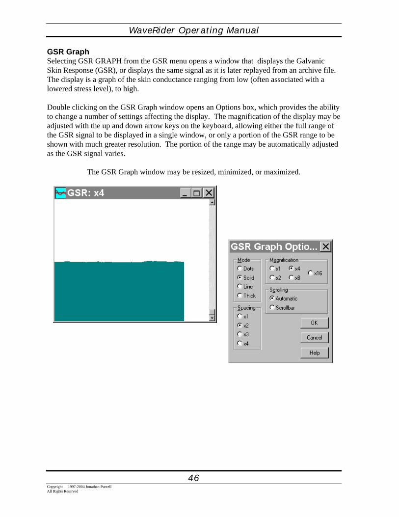
GSR GraphSelecting GSR GRAPH from the GSR menu opens a window that displays the GalvanicSkin Response (GSR), or displays the same signal as it is later replayed from an archive file.The display is a graph of the skin conductance ranging from low (often associated with alowered stress level), to high.
Double clicking on the GSR Graph window opens an Options box, which provides the abilityto change a number of settings affecting the display. The magnification of the display may beadjusted with the up and down arrow keys on the keyboard, allowing either the full range ofthe GSR signal to be displayed in a single window, or only a portion of the GSR range to beshown with much greater resolution. The portion of the range may be automatically adjustedas the GSR signal varies.
The GSR Graph window may be resized, minimized, or maximized.

WaveRider Operating Manual
47Copyright 1997-2004 Jonathan Purcell
All Rights Reserved
GSR Graph Options Dialog BoxThe GSR Graph Options Dialog Box provides the ability to adjust the appearance andcharacteristics of the GSR Graph window.
ModeFour types of display may be selected. The GSR graph may be drawn using only the DOTSrepresenting the individual data points. The default mode uses SOLID areas for greatervisibility. A continuous LINE may be drawn to represent the data, or a THICK line may beselected.
SpacingThe default x1 horizontal spacing uses one pixel per data point. If x2, x3,or x4 are selected,each point uses correspondingly more space in the window, making less data visible at onetime.
MagnificationBy selecting a magnification, ranging from x1 through x16, a varying amount of detail maybe seen in the GSR data. As the magnification is increased, more detail becomes visible, buta smaller range of data may be viewed in a given size window. A greater magnification, willcause the scrollbar to make more frequent adjustments to bring the current data into view.
ScrollingIf MAGNIFICATION is set so that the full range of GSR data cannot be displayed in thewindow, a scrollbar appears. If SCROLLBAR is selected, the scrollbar may be movedmanually to shift the the desired data into view. If AUTOMATIC scrolling is selected, thegraph will shift automatically, always keeping the most recent GSR data visible. In theautomatic mode, the scrollbar is not used to shift the display, but only serves to show whichpart of the range is being shown.
WaveRider Operating Manual
48Copyright 1997-2004 Jonathan PurcellAll Rights Reserved
MIDIMIDI stands for the Musical Instrument Digital Interface. MIDI is a protocol or languagespoken between electronic musical instruments and computer based music software andhardware. MIDI sends messages that are composed of note and velocity information. Thenote number refers to the pitch of the note and consists of a number between 0 & 127.Velocity is the loudness or volume of the note. Velocity also varies between 0 & 127. MIDIis a keyboard or piano based metaphor and it is sometimes helpful to think of it as such. Eachtime you produce a note there are two pieces of information sent along: the note and thevelocity. The velocity (or loudness) is so called because it is analogous to hitting the key onthe keyboard. The harder you hit it, the faster it moves, the louder the note.
There are several other types of messages in MIDI, controller messages, voice messages,pitch bend and system exclusive messages. Voice messages set the voice or instrument oneach channel. Continuous controllers provide the ability to do such things as add sustain,tremolo or pan between speakers. Sys ex or System Exclusive messages implement featuresthat are specific to a particular make and model of synthesizer. WaveWare does notimplement Sys ex messages but many synthesizers allow you to map controllers and/or notesto sys ex.
Most implementations of MIDI have 16 channels . Some early sound cards had 4 channels.Some high end systems provide the ability to multiplex providing supplemental banks ofchannels in multiples of 16 channels (16, 32 etc.). MIDI makes use of numbered channels.WaveRider has lettered biological channels (A,B,C,D).
You can map the output of one biological channel to up to 16 MIDI channels.
You can map more than one set of biological parameters from a single biologicalchannel to multiple MIDI channels simultaneously, (e.g. you can map the coherence fromchannel A to MIDI channel 1 and the Alpha from channel A to MIDI channel 2).
Generally it is not a good idea to have more than one biological output go to the same MIDIchannel unless you are careful to assign note values in each case that do not conflict. If thereis a conflict you will probably notice it when one voice grabs control of another channel.

WaveRider Operating Manual
49Copyright 1997-2004 Jonathan Purcell
All Rights Reserved
MIDI STRATEGIESWhen a scale is chosen in the MIDI OPTIONS DIALOG BOX particular attention should bepaid to the choice of range of MIDI notes. If the object is to make the output sound in scalethe tops and bottoms of the range should be octaves, fifths or some other significant note inthe scale structure.
The MIDI note numbers and their corresponding notes are provided below. Middle C is note60.
NOTE # NOTE NOTE # NOTE36 C 66 F#37 C# 67 G38 D 68 G#39 D# 69 A40 E 70 A#41 F 71 B42 F# 72 C43 G 73 C#44 G# 74 D45 A 75 D#46 A# 76 E47 B 77 F48 C 78 F#49 C# 79 G50 D 80 G#51 D# 81 A52 E 82 A#53 F 83 B54 F# 84 C55 G 85 C#56 G# 86 D57 A 87 D#58 A# 88 E59 B 89 F60 C 90 F#61 C# 91 G62 D 92 G#63 D# 93 A64 E 94 A#65 F 95 B
96 C
Here are some suggestions for musical strategies:
To play a blues riff start at the tonic and go to the fifth or seventh in one octave.
WaveRider Operating Manual
50Copyright 1997-2004 Jonathan PurcellAll Rights Reserved
To play a single pitch set the upper and lower note number the same.
Do the same for velocity.
Trying setting up several inputs that play one note only, but when played together form achord.
Have the note get lower and softer the more relaxed you become by switching the order of thenote numbers. Put the higher number first and the lower number second in the output portionof the MIDI Options Dialog Box.
For a rising parameter there are four options1. note raises, velocity raises2. note raises, velocity lowers3. note lowers, velocity raises4. note lowers, velocity lowers (good for relaxation)

WaveRider Operating Manual
51Copyright 1997-2004 Jonathan Purcell
All Rights Reserved
FFTS, DIGITAL FILTERS AND SIGNAL PROCESSINGThe Fast Fourier Transform (FFT) is a mathematical prism. Just as a prism splits white lightinto its component colors, an FFT splits a signal into its component frequencies. Anotherperspective is that the FFT sorts a signal into a set of frequency bins. The WaveRider's FFTsorts a signal into frequency bins one hertz wide.
An FFT takes a window or set of data points and converts this time window of data into a setof frequencies. The input data is considered to be in the "time domain," the output data is inthe "frequency domain." The WaveRider uses a one second window. In the slow bars mode anew window is begun every .25 seconds.
A digital filter performs a transfer function consisting of a collection of stop and pass bands.Pass bands let specific frequencies pass. Stop bands stop certain frequencies from passing.Most digital filters used in WaveWare have three bands, two stop bands and a pass band inthe middle. A digital filter also uses a window of data points. Unlike the FFT this window isrecalculated every time a new data point comes in. This makes digital filters much moreresponsive to signal variations than FFTs.

WaveRider Operating Manual
52Copyright 1997-2004 Jonathan PurcellAll Rights Reserved
Transform controls the characteristics of the global FFT parameters used in WaveWare.Select TRANSFORM... from the OPTIONS menu in WaveWare. Windowing refers to a setof co-efficients by which the data coming into the FFT are multiplied. The Windows havebeen designed to optimize time-frequency resolution trade-offs. The logarithmicity factorchanges the scaling of the output of the FFT. A higher number will increase the apparentpower of lower powered frequency bands in relation to the higher powered frequencies.
WindowingEach time the frequency transform is computed, it is calculated over a set of 128 consecutivedata points; this set of points is referred to as a Window. Because waves of a givenfrequency might not be at their zero-crossing at the edge of the window, it is often desirableto attenuate the data points near the window ends.
The Rectangular window uses the data points as they are, without attenuation; this optionrequires the least computation, thus reducing system loading and speeding response slightly.
The Hamming, Hanning, Triangular, and Blackman windowing options represent variousmathematical approaches to the attenuation of these end points. They offer different trade-offs between sensitivity of the transform, and reduction of harmonics.
Log PowerAfter the frequency transform is computed, the power is calculated for each frequency bandfrom 1 to 40 Hz. When this power spectrum is plotted, for example in the fast bars window,the power may be mapped linearly into the length of bars (Log Power = 0), or the power maybe mapped logarithmically into the length of bars. Selecting greater Log Power numbersserves to accentuate the low-power frequency bands, making them more visible relative to thehigher-power bands. Looking at Brain data, this markedly improves the visibility of the Betaregion.

WaveRider Operating Manual
53Copyright 1997-2004 Jonathan Purcell
All Rights Reserved
MINDGAMES: WAVERIDER LESSON PLANS

WaveRider Operating Manual
54Copyright 1997-2004 Jonathan PurcellAll Rights Reserved
Introduction
The MindFilled with confusionWho is its' guide?
Make itA sharp pointA smooth lakeA gentle breezeA mountains' root.-Bu Zhen Tsu
Have you ever gone to a party and thought about work the whole time?Or thought about the evening too much at work?Or carried on an internal dialogue when you should have been listening to what your loverwas trying to tell you?
Have you ever wished that you could just "change your mind" but have been unable to?
By learning the internal hallmarks, the sensations that you assoicate with specific brainwavestates, you can be the master of a flexible set of mental states. Eventually, you can learn toenter and leave mental states of intense concentration, relaxed attentiveness or deeprelaxation.
Using the WaveRider will help you to gain this self knowledge. Through repeated practice,you will learn what you need to do to enter into and switch between mental states.
You can think of the brainwave frequency spectrum as a continuum of arousal. On one end isthe delta of deep sleep on the other end the high frequency beta waves associated with themind engaged in a task. The alpha peak or dominant alpha frequency is a key point in thiscontinuum. Frequencies above it, tend to stimulate arousal. Frequencies below it, tend todecrease arousal. It is thought by some, that alpha represents an idling state which portionsof the brain return to after either completing or tiring of a task.
The alpha peak varies between individuals and changes with age. It tends to go up until theearly twenties then levels off until the the forties or fifties. It then decreases with old agegradually getting down into the Theta range. There is some speculation that this may be thereason for the resurfacing childhood in the aged. It has also been observed that the alphapeak tends to downshift with the length of time one meditates.
Peak performance is in many ways a choice of the appropriate level of brainwave frequencyalong this arousal/frequency continuum. This means being able to have the appropriatemental state for the situation, be it working at your job, playing at your sport, being on

WaveRider Operating Manual
55Copyright 1997-2004 Jonathan Purcell
All Rights Reserved
vacation or listening to your spouse. One might think of it as a type of emotional intelligenceor "choosing the right gear."
Learning about your brainwaves has to do with the learning to control rhythms generated indeep seated structures that control both cognition and emotional reaction. Regulation ofbrainwave states provides different modes of being for different tasks.
The following lessons when used with the WaveRider will set you off on a voyage of self-discovery. You will learn to be more relaxed or focused or multi-dimensional. You will gaininsight into your own body and mind. You should realize that this can be a long process.You will be changing your way of being, and this takes time. Practice regularly and do not getdiscouraged if your progress is slow.
You can use this book to train and become aware of different states of consciousness.Through practice you can get better at performing the tasks in each lesson. Ultimately, youshould learn to switch between different mental states and gain an attitudinal flexibilty thatyou can carry with you at all times.

WaveRider Operating Manual
56Copyright 1997-2004 Jonathan PurcellAll Rights Reserved
The Body: GSR, Heart & MuscleGSR
Configuration File: GSRUse Category: GSR
The GSR uses the skin resistance to train autonomic relaxation and arousal.
You can use the GSR to:• gain insight into your ability to control your levels of arousal• adjust your reaction to stress• Learn to use your breathing to relax.
The GSR measures your relative arousal level (the fight or flight response). When you areangry, sexually aroused or nervous your level of excitation goes up and makes your skinsweat. The more you sweat the more conductive your skin becomes. The WaveRidermeasures this response by passing a minute current of electricity through your body andmeasuring its voltage fluctuation.
Hooking Up1. From the FILE menu choose LOAD CONFIGURATION.2. Select GSR.CFG.3. Connect the electrodes as in the diagram. Use the finger electrodes and lead wires
provided. Use no electrode gel or paste. Make sure the electrodes are contacting skinthat is populated by sweat glands. Try to keep your fingers still. Some people like to putan electrode on each index finger although this makes it more difficult to interact withyour computer.
4. Turn the WaveRider on by clicking the ON button with your mouse or by using “Ctrl” +“o”.
5. The GSR moves relatively slowly. Try taking deep breaths or thinking about your debtsor ex-lover.

WaveRider Operating Manual
57Copyright 1997-2004 Jonathan Purcell
All Rights Reserved

WaveRider Operating Manual
58Copyright 1997-2004 Jonathan PurcellAll Rights Reserved
THINGS TO TRY
The Lying GameHook up your friend and ask them to pick a number between 1 and 10.Ask them one at time and in order, if each of the numbers between one and ten are thenumber that they chose.Ask them slowly and wait 5-10 seconds between each number to allow time for the GSR torespond.
Try varying whether or not the subject gets to view the screen or hear the sound. You canmute the sound by hitting F3 and unmute it with F4.
Try this several times and see if the subject can learn to lie effectively about which numberthey chose.
Discuss effective stategies.
Your Mother!!Insult various aspects of the subject's life including their family, bathroom habits, sexualprowess, intelligence and physical appearance. Note which subject area elicits the greatestresponse.
Ask the subject questions about any of the above.
Turn this into a game in which the subject tries to answer the question without showing anyresponse and the inquisitor tries to ask questions that will create a response.
Switch roles.
WaveRider Operating Manual
59Copyright 1997-2004 Jonathan Purcell
All Rights Reserved
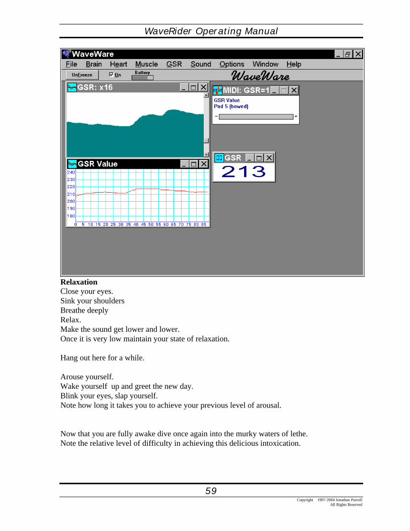
RelaxationClose your eyes.Sink your shouldersBreathe deeplyRelax.Make the sound get lower and lower.Once it is very low maintain your state of relaxation.
Hang out here for a while.
Arouse yourself.Wake yourself up and greet the new day.Blink your eyes, slap yourself.Note how long it takes you to achieve your previous level of arousal.
Now that you are fully awake dive once again into the murky waters of lethe.Note the relative level of difficulty in achieving this delicious intoxication.

WaveRider Operating Manual
60Copyright 1997-2004 Jonathan PurcellAll Rights Reserved
Adjustable ParametersThe GSR uses dynamic offset adjustment and provides different levels of resolution.You may need to use the COPY FROM GSR CHART button in the the MIDIOptions dialog box and the General Grapics dialog Box. This will copy the dynamicallyassigned range in the GSR Window into the selected dialog box. You may also use the spincontrols in the dialog box.

WaveRider Operating Manual
61Copyright 1997-2004 Jonathan Purcell
All Rights Reserved

WaveRider Operating Manual
62Copyright 1997-2004 Jonathan PurcellAll Rights Reserved
PLAYING WITH THE HEART RATE
Configuration File: HeartUse Category: Heart
The WaveRider allows you to• look at your heart rate and compare it to the heart rates of other people• notice how different things affect your momentary heart rate• evaluate the effects of different things on your heart rate.
The heart rate is the number of times per minute that the heart beats. The heart rate goes upand down depending on what you are doing or thinking as well as your state of health. Inaddition the heart rate varies between individuals. Some people have faster heart rates thanothers.
Hooking UpUse the Heart configuration to look and listen to your heart rate change.1. From the FILE menu choose LOAD CONFIGURATION.2. Select HEART.CFG.3. Connect the electrodes as in the diagram. Use the disposable electrodes and lead wires
provided.4. Turn the WaveRider on by clicking the ON button with your mouse or by using “Ctrl” +
“o”.5. The heart strip chart should have a clean signal if the electrodes are properly connected.

WaveRider Operating Manual
63Copyright 1997-2004 Jonathan Purcell
All Rights Reserved
CHANNELS USED FOR HEART MODE VARY BETWEEN MODELS AND MAYDIFFER FROM WHAT IS SHOWN

WaveRider Operating Manual
64Copyright 1997-2004 Jonathan PurcellAll Rights Reserved
THINGS TO TRY
Questions• Which will lower your heart rate more, deep breathing or shallow breathing.• What effect does caffiene, sugar or alcohol have on your heart rate.• What happens if you think about your lover, an academic test or your financial situation?• Try measuring your heart rate before exercise, immediately after exercise and half an hour
after exercise.• What happens to your heart rate after you make love?• What happens to your heart rate before during and after you smoke a cigarette? After you
quit smoking?• What happens to your heart rate when you watch a horror or action movie?• Measure the heart rate of some friends. Talk before hand about who will have the highest
and lowest heart rate.• Discuss the results

WaveRider Operating Manual
65Copyright 1997-2004 Jonathan Purcell
All Rights Reserved

WaveRider Operating Manual
66Copyright 1997-2004 Jonathan PurcellAll Rights Reserved
MUSCLE
Configuration File: MUSCLEUse Category: MUSCLE
Use the muscle configuration to:• relax or• play music with your muscles.
When you tense your muscles they produce an envelope of broadband electrical activity thatranges from 20 to 1000 hertz. The WaveRider measures this envelope of electrical outputand allows you to output it graphically or as sound.
Hooking Up1. From the FILE menu choose LOAD CONFIGURATION.2. Select MUSCLE.CFG.3. Connect the electrodes as in the diagrams, or put them on a different set of muscle
groups. Use the disposable electrodes and lead wires provided.4. Turn the WaveRider on by clicking the ON button with your mouse or by using ""Ctrl O."5. The muscle strip chart should have a clean signal if the electrodes are properly connected.6. Flex or relax your muscles

WaveRider Operating Manual
67Copyright 1997-2004 Jonathan Purcell
All Rights Reserved

WaveRider Operating Manual
68Copyright 1997-2004 Jonathan PurcellAll Rights Reserved

WaveRider Operating Manual
69Copyright 1997-2004 Jonathan Purcell
All Rights Reserved
Things to TryIf you are using the muscle configuration to play music, try setting different threshold levelsso that you can create periods of silence and noise.
If you are using the muscle configuration to train relaxation you may need to raise thesensitivity.Try relaxing to get the sound to go down.Think about something stessful and notice the response you get.

WaveRider Operating Manual
70Copyright 1997-2004 Jonathan PurcellAll Rights Reserved
Adjustable ParametersTo change the audio output, double click on the MIDI window with your mouse. The dialogbox pictured above will be displayed. You can test the effects of your changes by clickingAPPLY. When you are satisfied hit OK.
If it is too easy to get over the threshold (make the music start):Make the lower number in Amplitude Range (uV) (currently 35) higher.
If it is too hard to get over the threshold (make the music start):Make the lower number in Amplitude Range (uV) (currently 35) lower.
If you hit the high note too easily:Make the higher number in Amplitude Range (uV) (currently 140) higher.
If you don't have a large enough range of notes:Make the range of notes (currently 48-72) wider.
If you want the tone to get lower instead of higher:Reverse the Note numbers.

WaveRider Operating Manual
71Copyright 1997-2004 Jonathan Purcell
All Rights Reserved
RELAX
You can use the WaveRider to play with your alpha waves.
Many people in todays' overstressed world have difficulty relaxing or letting go. Alphawaves provide a way to relax deeply and also a way to relax while remaining attentive.
You can produce alpha waves by closing your eyes and relaxing. Some people report thatthey produce alpha with their eyes closed after they have "given up," or let go of their ego.When they have ceased to try.
Alpha wave rhythms are generated deep in the brain in the thalamus. They are radiated to thecerebral cortex. There tends to be a lot of alpha generated in the occipital lobe in the back ofthe head when the eyes are closed.
Most people can generate alpha without too much effort. Usually this comes as alpha flaresor short burst of alpha. Once you get good at producing alpha, try to maintain a consistentlevel. Also, try to purposefully change your level of alpha.
The following lessons will show you a number of ways to play with alpha waves:
You can learn to relax yet remain attentive.You can learn to relax more fully.You can learn to clear your mind.You can validate other forms of relaxation.

WaveRider Operating Manual
72Copyright 1997-2004 Jonathan PurcellAll Rights Reserved
PER CENT ALPHA
Closed Eye Relaxation
Configuration File: %ALPHAUse Category: BRAIN
Per Cent Alpha uses the ratio of alpha waves to the entire brainwave spectrum to trainrelaxation.
You can use Per Cent Alpha to:• relax• adjust your reaction to stress• guide yourself into an egoless state of mind
HOOKING UPUse the PER CENT ALPHA configuration to use your brainwaves to relax.1. From the FILE menu choose LOAD CONFIGURATION.2. Select %ALPHA.CFG.3. Connect the electrodes as in the diagram. Use the cup electrodes supplied and the ten-20
paste. Make sure that the skin is clean and you have a good contact.4. Turn the WaveRider on by clicking the ON button with your mouse or by using “Ctrl” +
“o”.5. The brain strip chart should have a clean signal if the electrodes are properly connected.6. Close your eyes. Relax. Drop your shoulders. Make the note go up.
Close your eyesDrop your shouldersTake a few deep breathsClear your mindLet go

WaveRider Operating Manual
73Copyright 1997-2004 Jonathan Purcell
All Rights Reserved

WaveRider Operating Manual
74Copyright 1997-2004 Jonathan PurcellAll Rights Reserved
Questions?What can you do to produce alpha?
If you think about different colors does it help you to produce alpha?
Are there body positions in which you are more able to produce alpha?
Are there parts of your body that you can think about that will help you to produce alpha?Your shoulders? The top of your head? The Space between your ears?
Can you do it with your eyes open?
What makes you go into alpha reliably?
What makes you leave alpha reliably?

WaveRider Operating Manual
75Copyright 1997-2004 Jonathan Purcell
All Rights Reserved
Adjustable ParametersTo change the audio output, double click on the MIDI window with your mouse. The dialogbox pictured above will be displayed. You can test the effects of your changes by clickingAPPLY. When you are satisfied hit OK.
If it is too easy to get over the threshold (make the music start):Make the lower number in % Ratio A/B (currently 32) higher.
If it is too hard to get over the threshold (make the music start):Make the lower number in % Ratio A/B (currently 32) lower.
If you hit the high note too easily.Make the higher number in % Ratio A/B (currently 50) higher.
If you don't have a large enough range of notes.Make the range of notes (currently 60-72) wider or lower the the higher number in
% Ratio A/B (currently 50).If you want the tone to get lower instead of higher.
Reverse the Note numbers.

WaveRider Operating Manual
76Copyright 1997-2004 Jonathan PurcellAll Rights Reserved
PER CENT HI-ALPHA
Open Eye Relaxation
Configuration File: %HIALPHAUse Category: BRAIN
Per Cent Hi-Alpha uses the ratio of Hi-alpha waves (10-13 Hertz) to the entire brainwavespectrum (4-40 hertz) to train relaxed attentiveness.
You can use Per Cent Hi-Alpha to:• learn a sense of presence• quell your internal dialogue• be alert but relaxed
HOOKING UPUse Per Cent Hi-Alpha configuration to get a sense of relaxed attentiveness.1. From the FILE menu choose LOAD CONFIGURATION.2. Select %HIALPHA.CFG.3. Connect the electrodes as in the diagram. Use the cup electrodes supplied and the ten-20
paste. Make sure that the skin is clean and you have a good contact.4. Turn the WaveRider on by clicking the ON button with your mouse or by using “Ctrl” +
“o”.5. The brain strip chart should have a clean signal if the electrodes are properly connected.6. With your eyes opened relax while remaining attentive. Drop your shoulders. Make the
note go up.

WaveRider Operating Manual
77Copyright 1997-2004 Jonathan Purcell
All Rights Reserved

WaveRider Operating Manual
78Copyright 1997-2004 Jonathan PurcellAll Rights Reserved
Questions?
What can you do to produce hi-alpha?
What feeling does it give you?
When do you feel like this in your daily life?
When would this feeling be useful?
Are there body positions in which you are more able to produce hi-alpha?
Can you produce hi-alpha with your eyes shut?
What makes you reliably go into hi-alpha?
What makes you reliably leave hi-alpha?

WaveRider Operating Manual
79Copyright 1997-2004 Jonathan Purcell
All Rights Reserved
Adjustable ParametersTo change the audio output, double click on the MIDI window with your mouse. The dialogbox pictured above will be displayed. You can test the effects of your changes by clickingAPPLY. When you are satisfied hit OK.
If it is too easy to get over the threshold (make the music start):Make the lower number in % Ratio A/B (currently 25) higher.
If it is too hard to get over the threshold (make the music start):Make the lower number in % Ratio A/B (currently 25) lower.
If you hit the high note too easily:Make the higher number in % Ratio A/B (currently 50) higher.
If you don't have a large enough range of notes:Make the range of notes (currently 60-72) wider or lower thehigher number in % Ratio A/B (currently 50).
If you want the tone to get lower instead of higher:Reverse the Note numbers.

WaveRider Operating Manual
80Copyright 1997-2004 Jonathan PurcellAll Rights Reserved
ALPHA AMPLITUDE
Closed Eye Relaxation
Configuration File: ALPHAMPUse Category: BRAIN
Alpha Amplitude uses the alpha waves to train relaxation.
You can use the Alpha Amplitude to:• relax• adjust your reaction to stress• guide yourself into an egoless state of mind
HOOKING UPUse the Alpha Amplitude configuration to use your brainwaves to relax.1. From the FILE menu choose LOAD CONFIGURATION.2. Select ALFAMP.CFG.3. Connect the electrodes as in the diagram. Use the cup electrodes supplied and the ten-20
paste. Make sure that the skin is clean and you have a good contact.4. Turn the WaveRider on by clicking the ON button with your mouse or by using “Ctrl” +
“o”.5. The brain strip chart should have a clean signal if the electrodes are properly connected.
Close your eyesDrop your shouldersTake a few deep breathsClear your mindLet go

WaveRider Operating Manual
81Copyright 1997-2004 Jonathan Purcell
All Rights Reserved

WaveRider Operating Manual
82Copyright 1997-2004 Jonathan PurcellAll Rights Reserved
Questions?What can you do to produce alpha?
If you think about different colors does it help you to produce alpha?
Are there body positions in which you are more able to produce alpha?
Are there parts of your body that you can think about that will help you to produce alpha?Your shoulders? the top of your head?
Can you do it with your eyes open?
What makes you reliably go into alpha?
What makes you reliably leave alpha?

WaveRider Operating Manual
83Copyright 1997-2004 Jonathan Purcell
All Rights Reserved
Adjustable ParametersTo change the audio output, double click on the MIDI window with your mouse. The dialogbox pictured above will be displayed. You can test the effects of your changes by clickingAPPLY. When you are satisfied hit OK.
If it is too easy to get over the threshold (make the music start):Make the lower number in Range (uV) (currently 10.0) higher.
If it is too hard to get over the threshold (make the music start):Make the lower number in Range (uV) (currently 10.0) lower.
If you hit the high note too easily.Make the higher number in Range (uV) (currently 18.0) higher.
If you don't have a large enough range of notes.Make the range of notes (currently 60-72) wider.
If you want the tone to get lower instead of higher.Reverse the Note numbers.

WaveRider Operating Manual
84Copyright 1997-2004 Jonathan PurcellAll Rights Reserved
GSR / % ALPHA
Deep Relaxation
Configuration File: GSR-ALPHUse Category: BRAIN GSR
GSR/% Alpha combines the GSR mode for relaxation of the autonomic nervous system withclosed eye brainwave relaxation. It is especially good for getting into deep relaxation.
HOOKING UPUse the GSR/%Alpha configuration to deeply relax.1. From the FILE menu choose LOAD CONFIGURATION.2. Select GSR-Alph.CFG.3. Connect the electrodes as in the diagram. Use the cup electrodes supplied and the ten-
20 paste for the brain electrodes. Make sure that the skin is clean and you have a goodcontact. Use no paste with the GSR electrodes.
4. Turn the WaveRider on by clicking the ON button with your mouse or by using ""CtrlO."
5. The brain strip chart should have a clean signal if the electrodes are properly connected.6. Close your eyes. Relax. Drop your shoulders. Make the notes go lower.7. The GSR (oboe sound) will react slowly.

WaveRider Operating Manual
85Copyright 1997-2004 Jonathan Purcell
All Rights Reserved

WaveRider Operating Manual
86Copyright 1997-2004 Jonathan PurcellAll Rights Reserved
Things to DoClose your eyes.Breathe deeply.Drop your shoulders.Make the note get lower.You should get so relaxed that your chin falls on your chest.Be sure to adjust the GSR for your readings.

WaveRider Operating Manual
87Copyright 1997-2004 Jonathan Purcell
All Rights Reserved
Adjustable Parameters
The GSR uses dynamic offset adjustment and provides different levels of resolution.You may need to use the COPY FROM GSR CHART button in the the MIDIOptions dialog box and the General Grapics dialog Box. This will copy the dynamicallyassigned range in the GSR Window into the selected dialog box. You may also use the spincontrols in the dialog box.

WaveRider Operating Manual
88Copyright 1997-2004 Jonathan PurcellAll Rights Reserved
ALPHA/THETAALPHA/THETA WITH 2 TONES
ALPHTHET.CFGUse the alpha/theta with 2 tones configuration to learn the boundary between alpha and theta.You can try this configuration with your eyes opened or closed.1. From the FILE menu choose LOAD CONFIGURATION.2. Select alphthet.cfg3. Connect the electrodes as in the diagram. Use the cup electrodes supplied and the ten-
20 paste. Make sure that the skin is clean and you have a good contact.4. Turn the WaveRider on by clicking the ON button with your mouse or by using “Ctrl” +
“o”.5. The brain strip chart should have a clean signal if the electrodes are properly connected.6. The flute sound is theta and the pad is alpha. Find out what makes you switchbetween these two types of brainwaves.

WaveRider Operating Manual
89Copyright 1997-2004 Jonathan Purcell
All Rights Reserved

WaveRider Operating Manual
90Copyright 1997-2004 Jonathan PurcellAll Rights Reserved
Adjustable ParametersTo change the audio output, double click on the MIDI window with your mouse. The dialogbox pictured above will be displayed. You can test the effects of your changes by clickingAPPLY. When you are satisfied hit OK.
If it is too easy to get over the threshold (make the music start):Make the lower number in Range (uV) (currently 10) higher.
If it is too hard to get over the threshold (make the music start):Make the lower number in Range (uV) (currently 10) lower.
If you hit the high note too easily.Make the hihger number in Range (uV) (currently 30) higher.
If you don't have a large enough range of notes.Make the range of notes (currently 48-72) wider or lower the the higher number in
Range (uV) (currently 30).If you want the tone to get lower instead of higher.
Reverse the Note numbers.

WaveRider Operating Manual
91Copyright 1997-2004 Jonathan Purcell
All Rights Reserved

WaveRider Operating Manual
92Copyright 1997-2004 Jonathan PurcellAll Rights Reserved
ALPHA/THETA FOR 2 CHANNELS
A-T-2CH.CFG
Use the alpha/theta for 2 channels configuration to evaluate the levels of Alpha and Theta onboth sides of the brain.1. From the FILE menu choose LOAD CONFIGURATION.2. Select A-T-2ch.Cfg.3. Connect the electrodes as in the diagram. Use the cup electrodes supplied and the ten-
20 paste. Make sure that the skin is clean and you have a good contact.4. Turn the WaveRider on by clicking the ON button with your mouse or by “Ctrl” + “o”.5. Both brain strip charts should have a clean signal if the electrodes are properly
connected.

WaveRider Operating Manual
93Copyright 1997-2004 Jonathan Purcell
All Rights Reserved

WaveRider Operating Manual
94Copyright 1997-2004 Jonathan PurcellAll Rights Reserved
WaveRider Operating Manual
95Copyright 1997-2004 Jonathan Purcell
All Rights Reserved
FOCUS
Use the WaveRider to learn how to improve concentration.
The concentration exercises that follow should be thought of as a starting point. Settingsshould be adjusted to accomodate individuals.
Increasing the power in higher frequency brainwave bands and decreasing power in lowerfrequency bands can improve concentration and attention. The higher range frequencies mayinclude: 12-15 Hertz (SMR), 15-18 Hertz (Beta), 14 Hertz, 16-21 Hertz and 12-22 Hertzeetc. Lower frequency bands may include 4-8 Hertz, 2-6 Hertz, 2-7 Hertz, 5-8 Hertz etc.There are a variety of opinions on the efficacy of different protocols as there are on electrodeplacements.
BETA/THETA trains the increase of BETA (15-18 Hertz) and the decrease of Theta.
SMR/THETA trains the increase of SMR (12-15 Hertz) and the decrease of Theta.
THETA SUPPRESS simply suppresses Theta.

WaveRider Operating Manual
96Copyright 1997-2004 Jonathan PurcellAll Rights Reserved
BETA/THETA
Open Eye Concentration
Configuration File: BET-THETUse Category: BRAIN
This configuration uses an increase of Beta and decrease of Theta to train concentration.
You can use BETA/THETA to:• learn to concentrate better• learn to pay attention• be alert
HOOKING UPUse BETA/THETA configuration to get a sense of concentration.1. From the FILE menu choose LOAD CONFIGURATION.2. Select BET-THET.CFG.3. Connect the electrodes as in the diagram. Use the cup electrodes supplied and the ten-
20 paste. Make sure that the skin is clean and you have a good contact.4. Turn the WaveRider on by clicking the ON button with your mouse or by “Ctrl” + “o”.5. The brain strip chart should have a clean signal if the electrodes are properly connected.6. With your eyes opened focus your attention. Make the note go up.

WaveRider Operating Manual
97Copyright 1997-2004 Jonathan Purcell
All Rights Reserved

WaveRider Operating Manual
98Copyright 1997-2004 Jonathan PurcellAll Rights Reserved
THINGS TO TRYRead a book.Look at the details in an intricate piece of artwork.Do something that is interesting to you.Listen to a person or tape that has a lot of information.
QUESTIONSWhat do you have to do to change the tone?What feeling does this give you?Can you reproduce this feeling without the WaveRider?When would it be appropriate to have this mental attitude?When would it be inappropriate?
In a GroupWho will be able to most consistently focus?Who will be able to focus the longest?What does it feel like when you focus?When can this mental attitude help you?

WaveRider Operating Manual
99Copyright 1997-2004 Jonathan Purcell
All Rights Reserved
Beta/Theta makes use of the Reward Suppress Using Filters algorithm. This algorithmouputs a range of notes based on a range of ratios of two frequency bands. The output onlyoccurs though, if certain threshold conditions are met.
In this case:
If Beta is above 2.0 microVoltsAnd Theta is below 7.0 microVoltsAnd Delta (1.5-4 hertz) is below 20 microVolts,
Then the ratio of Beta to theta from 60 to 130 percent will be mapped to MIDI notes 60(middle C) to 84 (the C two octaves above middle C).
If the ratio goes below the threshold of 60 per cent or above 130 per cent no audio will beoutput.
To modify these thresholds, first observe the Beta, Theta and Delta General GraphicsWindows to the left.

WaveRider Operating Manual
100Copyright 1997-2004 Jonathan PurcellAll Rights Reserved
SMR/ THETA
Open Eye Concentration
Configuration File: SMR-THETUse Category: BRAIN
This configuration uses an increase of SMR and decrease of Theta to train concentration.
You can use SMR/THETA to:• learn to concentrate better• learn to pay attention• be alert
HOOKING UPUse the SMR/THETA configuration to get a sense of concentration1. From the FILE menu choose LOAD CONFIGURATION.2. Select SMR-THET.CFG.3. Connect the electrodes as in the diagram. Use the cup electrodes supplied and the ten-
20 paste. Make sure that the skin is clean and you have a good contact.4. Turn the WaveRider on by clicking the ON button with your mouse or by using “Ctrl” +
“o”.5. The brain strip chart should have a clean signal if the electrodes are properly connected.6. With your eyes opened focus your attention. Make the note go up.
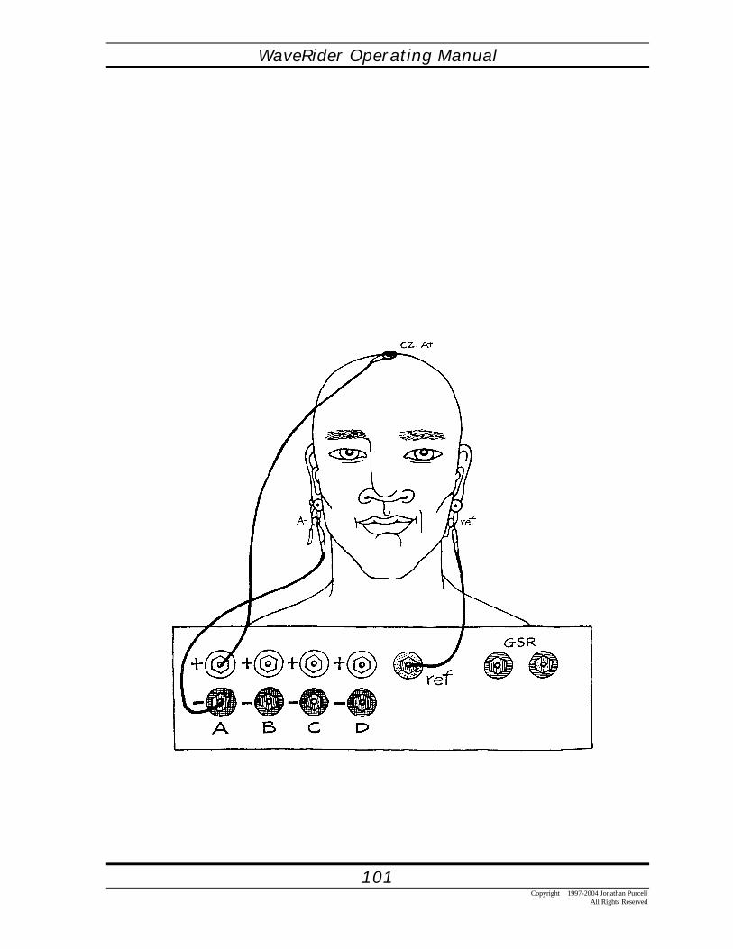
WaveRider Operating Manual
101Copyright 1997-2004 Jonathan Purcell
All Rights Reserved

WaveRider Operating Manual
102Copyright 1997-2004 Jonathan PurcellAll Rights Reserved
THINGS TO TRYRead a book.Look at the details in an intricate piece of artwork.Do something that is interesting to you.Listen to a person or tape that has a lot of information.
QUESTIONSWhat do you have to do to change the tone?What feeling does this give you?Can you reproduce this feeling without the WaveRider?When would it be appropriate to have this mental attitude?When would it be inappropriate?
In a GroupWho will be able to most consistently focus?Who will be able to focus the longest?What does it feel like when you focus?When can this mental attitude help you?

WaveRider Operating Manual
103Copyright 1997-2004 Jonathan Purcell
All Rights Reserved
SMR/Theta makes use of the Reward Suppress Using Filters algorithm. This algorithmouputs a range of notes based on a range of ratios of two frequency bands. The output onlyoccurs though, if certain threshold conditions are met.
In this case:If SMR is above 2.0 microVoltsAnd Theta is below 7.0 microVoltsAnd Delta (1.5-4 hertz) is below 20 microVolts,
Then the ratio of Beta to theta from 60 to 130 percent will be mapped to MIDI notes 60(middle C) to 84 (the C two octaves above middle C).
If the ratio goes below the threshold of 60 per cent or above 130 per cent no audio will beoutput.
To modify these thresholds, first observe the SMR, Theta and Delta General GraphicsWindows to the left.

WaveRider Operating Manual
104Copyright 1997-2004 Jonathan PurcellAll Rights Reserved
THETA SUPPRESS
Open Eye Concentration
Configuration File: THETASUPUse Category: BRAIN
This configuration uses a decrease of Theta to train concentration. It is a good state of mindfor learning new material.
You can use Theta Suppress to:• learn to concentrate better• learn new material• be alert
HOOKING UPUse the Theta Suppress configuration to get a sense of concentration1. From the FILE menu choose LOAD CONFIGURATION.2. Select THETASUP.CFG.3. Connect the electrodes as in the diagram. Use the cup electrodes supplied and the ten-
20 paste. Make sure that the skin is clean and you have a good contact.4. Turn the WaveRider on by clicking the ON button with your mouse or by using ""Ctrl
O."5. The brain strip chart should have a clean signal if the electrodes are properly connected.6. With your eyes opened focus your attention. Make the note go up.

WaveRider Operating Manual
105Copyright 1997-2004 Jonathan Purcell
All Rights Reserved

WaveRider Operating Manual
106Copyright 1997-2004 Jonathan PurcellAll Rights Reserved
THINGS TO TRYRead a book.Look at the details in an intricate piece of artwork.Do something that is interesting to you.Listen to a person or tape that has a lot of information.
QUESTIONSWhat do you have to do to change the tone?What feeling does this give you?Can you reproduce this feeling without the WaveRider?When would it be appropriate to have this mental attitude?When would it be inappropriate?
In a GroupWho will be able to most consistently focus?Who will be able to focus the longest?What does it feel like when you focus?When can this mental attitude help you?

WaveRider Operating Manual
107Copyright 1997-2004 Jonathan Purcell
All Rights Reserved
Adjustable ParametersTo change the audio output, double click on the MIDI window with your mouse. The dialogbox pictured above will be displayed. You can test the effects of your changes by clickingAPPLY. When you are satisfied hit OK.
If it is too hard to hit the high note:Make the lower number in Range (uV) (currently 0) higher.
If you want the tone to get lower instead of higher.Reverse the Note numbers.
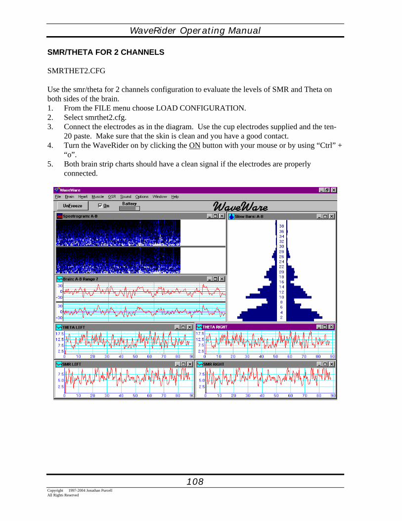
WaveRider Operating Manual
108Copyright 1997-2004 Jonathan PurcellAll Rights Reserved
SMR/THETA FOR 2 CHANNELS
SMRTHET2.CFG
Use the smr/theta for 2 channels configuration to evaluate the levels of SMR and Theta onboth sides of the brain.1. From the FILE menu choose LOAD CONFIGURATION.2. Select smrthet2.cfg.3. Connect the electrodes as in the diagram. Use the cup electrodes supplied and the ten-
20 paste. Make sure that the skin is clean and you have a good contact.4. Turn the WaveRider on by clicking the ON button with your mouse or by using “Ctrl” +
“o”.5. Both brain strip charts should have a clean signal if the electrodes are properly
connected.

WaveRider Operating Manual
109Copyright 1997-2004 Jonathan Purcell
All Rights Reserved
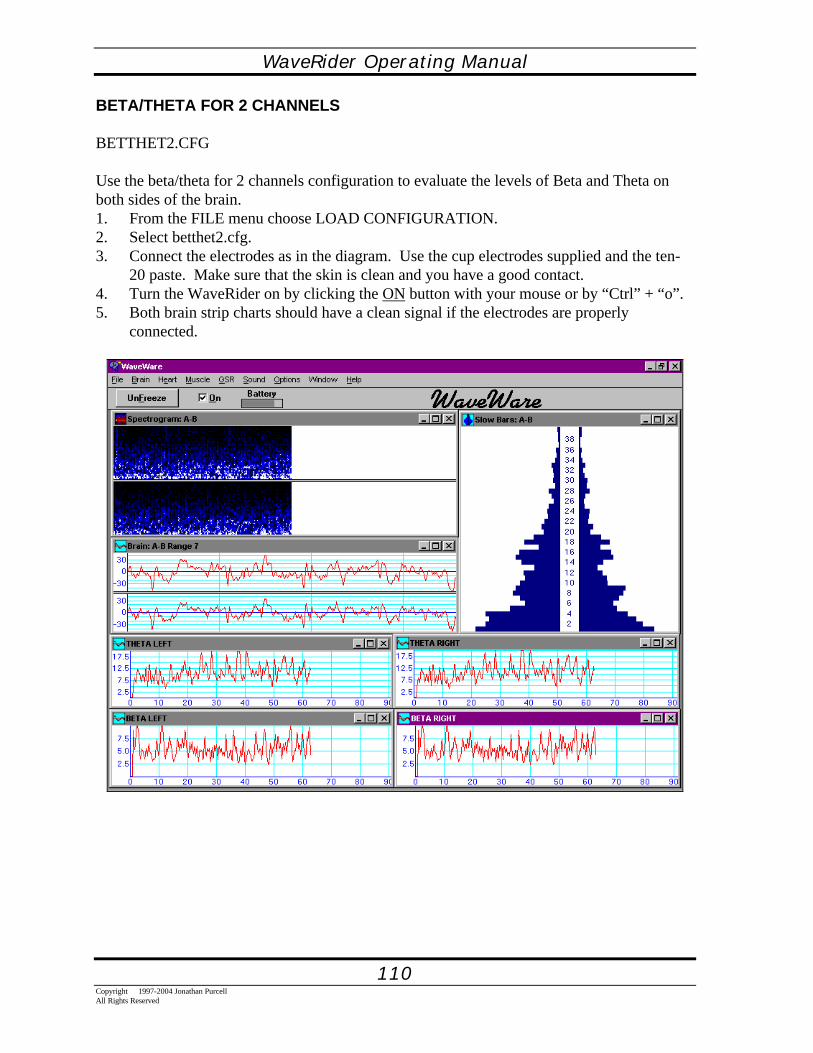
WaveRider Operating Manual
110Copyright 1997-2004 Jonathan PurcellAll Rights Reserved
BETA/THETA FOR 2 CHANNELS
BETTHET2.CFG
Use the beta/theta for 2 channels configuration to evaluate the levels of Beta and Theta onboth sides of the brain.1. From the FILE menu choose LOAD CONFIGURATION.2. Select betthet2.cfg.3. Connect the electrodes as in the diagram. Use the cup electrodes supplied and the ten-
20 paste. Make sure that the skin is clean and you have a good contact.4. Turn the WaveRider on by clicking the ON button with your mouse or by “Ctrl” + “o”.5. Both brain strip charts should have a clean signal if the electrodes are properly
connected.
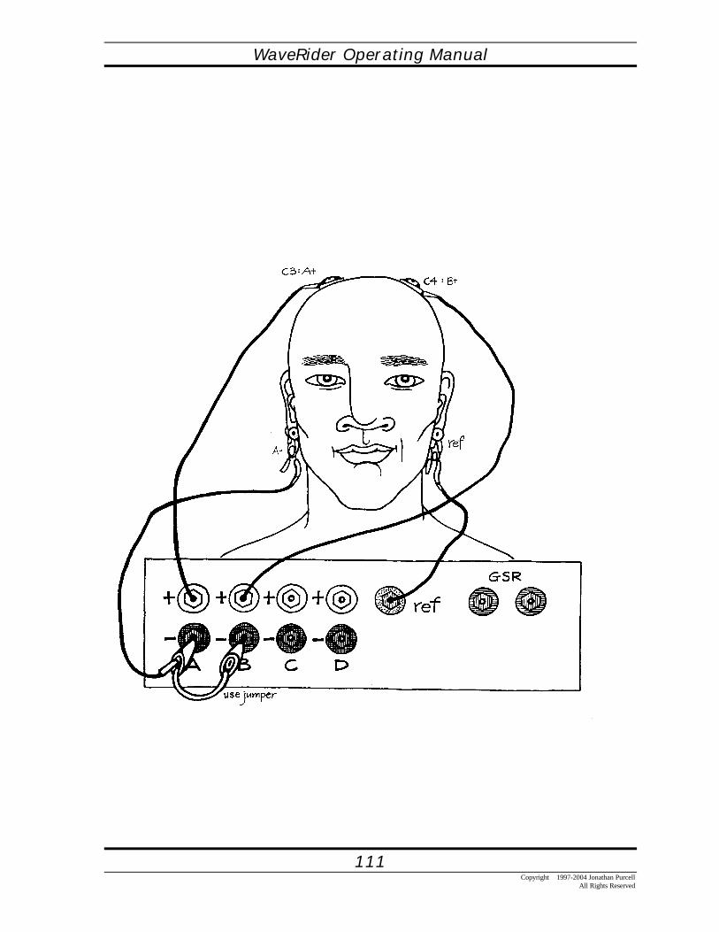
WaveRider Operating Manual
111Copyright 1997-2004 Jonathan Purcell
All Rights Reserved

WaveRider Operating Manual
112Copyright 1997-2004 Jonathan PurcellAll Rights Reserved
ASSESSMENT
BRAIN REFLECTOR
REFLECTR.CFG
Use the Brain Reflector configuration to look at all of the frequencies on both sides of thebrain.1. From the FILE menu choose LOAD CONFIGURATION.2. Select reflectr.cfg.3. Connect the electrodes as in the diagram. Use the cup electrodes supplied and the ten-
20 paste. Make sure that the skin is clean and you have a good contact.4. Turn the WaveRider on by clicking the ON button with your mouse or by “Ctrl” + “o”.5. Both brain strip charts should have a clean signal if the electrodes are properly
connected.6. With your eyes opened relax while remaining attentive. Drop your
shoulders.

WaveRider Operating Manual
113Copyright 1997-2004 Jonathan Purcell
All Rights Reserved

WaveRider Operating Manual
114Copyright 1997-2004 Jonathan PurcellAll Rights Reserved
CHECKER
CHECKER.CFG
Use the checker configuration to evaluate the levels of the delta, theta, alpha and betabrainwaves for setting threshholds and ranges on other configurations.1. From the FILE menu choose LOAD CONFIGURATION.2. Select checker.Cfg.3. Connect the electrodes as in the diagram. Use the cup electrodes supplied and the ten-
20 paste. Make sure that the skin is clean and you have a good contact.4. Turn the WaveRider on by clicking the ON button with your mouse or by using “Ctrl” +
“o”.5. Both brain strip charts should have a clean signal if the electrodes are properly
connected.

WaveRider Operating Manual
115Copyright 1997-2004 Jonathan Purcell
All Rights Reserved

WaveRider Operating Manual
116Copyright 1997-2004 Jonathan PurcellAll Rights Reserved
JUST FOR FUN
BLUES ENSEMBLE
Brainwave and Muscle Jam
Configuration File: BLUESEEUse Category: BRAIN AND MUSCLE
Bluesee is a fun way to play music with your body and mind
HOOKING UPUse Bluesee configuration to play with your body and mind1. From the FILE menu choose LOAD CONFIGURATION.2. Select BLUESEE.CFG.3. Connect the electrodes as in the diagram. Use the cup electrodes supplied and the ten-
20 paste to connect to the brain. Make sure that the skin is clean and you have a goodcontact. Use the disposable electrodes for the arms.
4. Turn the WaveRider on by clicking the ON button with your mouse or by “Ctrl” + “o”.5. The brain strip chart should have a clean signal if the electrodes are properly connected.6. Flex your arms. Create alpha waves with your brain.

WaveRider Operating Manual
117Copyright 1997-2004 Jonathan Purcell
All Rights Reserved
Things to DoKeep your arms still at your side.Flex your arms individually.Try to play the lower notes by flexing just a little bit.Play the higher notes by flexing more.
Close your eyes and relax.Produce alpha waves.Make the saxophone wail.

WaveRider Operating Manual
118Copyright 1997-2004 Jonathan PurcellAll Rights Reserved

WaveRider Operating Manual
119Copyright 1997-2004 Jonathan Purcell
All Rights Reserved
PROGRAMMING WAVEWARE
WaveRider Operating Manual
120Copyright 1997-2004 Jonathan PurcellAll Rights Reserved
THE GENERAL GRAPHICS AND THE MIDI OPTIONS DIALOGBOXESThe MIDI Options Dialog Box and the General Graphics Options Dialog Box are theessential elements of control in WaveWare. They are the means by which musical setups andgraphs of processed data are created and modified. In addition the General GraphicsWindows are responsible for exporting data as both ASCII and DDE streams. Both types ofdialog boxes have many features and deserve close scrutiny.
The two types of dialog boxes are separate. Changing the MIDI Options does not change theGeneral Graph. This allows a great deal of flexibility in designing configurations butnecessitates a certain amount of attention. If you have a MIDI and General Graph windowthat are representing a similar signal characteristic, you may want to change one if youchange the other.
The settings for General Graph and MIDI will ordinarily be different. In the MIDI Output theoutput parameters define the upper and lower thresholds of the MIDI output. In the GeneralGraph output they define the top and bottom of the Y-axis. Usually the General Graph outputhas a wider range than the MIDI output. If the settings are the same, then the line goes off thegraph when the signal goes outside threshhold.
The MIDI Options Dialog Box and the General Graphics Options Dialog Box make use ofthe same input algorithms. All input algorithms are displayed in all MIDI Options DialogBoxes, but only those input algorithms that match the use category of the selected GeneralGraphics Dialog Box are displayed. (e.g. Heart input algorithm is displayed in all MIDIoptions dialog boxes, but is only displayed in heart General Graphics Dialog boxes).
This section is organized as follows: First a description of the fixed portions of the MIDIOptions Dialog Box and the General Graphics Options Dialog Box. Then each algorithmwill be described in turn.
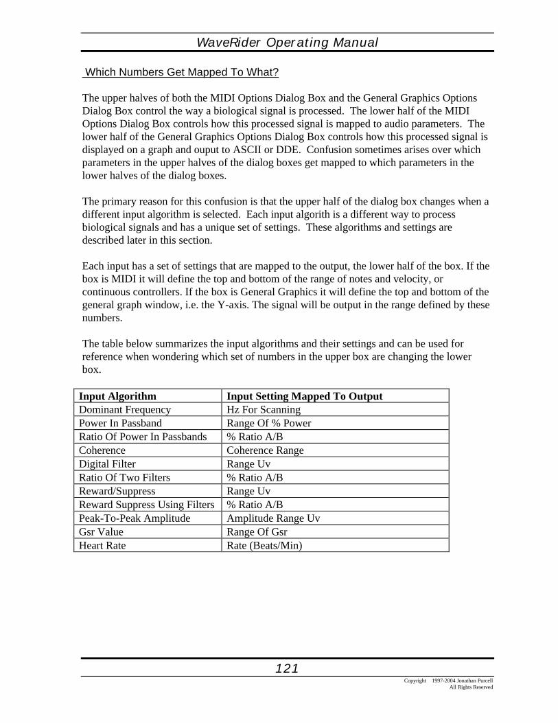
WaveRider Operating Manual
121Copyright 1997-2004 Jonathan Purcell
All Rights Reserved
Which Numbers Get Mapped To What?
The upper halves of both the MIDI Options Dialog Box and the General Graphics OptionsDialog Box control the way a biological signal is processed. The lower half of the MIDIOptions Dialog Box controls how this processed signal is mapped to audio parameters. Thelower half of the General Graphics Options Dialog Box controls how this processed signal isdisplayed on a graph and ouput to ASCII or DDE. Confusion sometimes arises over whichparameters in the upper halves of the dialog boxes get mapped to which parameters in thelower halves of the dialog boxes.
The primary reason for this confusion is that the upper half of the dialog box changes when adifferent input algorithm is selected. Each input algorith is a different way to processbiological signals and has a unique set of settings. These algorithms and settings aredescribed later in this section.
Each input has a set of settings that are mapped to the output, the lower half of the box. If thebox is MIDI it will define the top and bottom of the range of notes and velocity, orcontinuous controllers. If the box is General Graphics it will define the top and bottom of thegeneral graph window, i.e. the Y-axis. The signal will be output in the range defined by thesenumbers.
The table below summarizes the input algorithms and their settings and can be used forreference when wondering which set of numbers in the upper box are changing the lowerbox.
Input Algorithm Input Setting Mapped To OutputDominant Frequency Hz For ScanningPower In Passband Range Of % PowerRatio Of Power In Passbands % Ratio A/BCoherence Coherence RangeDigital Filter Range UvRatio Of Two Filters % Ratio A/BReward/Suppress Range UvReward Suppress Using Filters % Ratio A/BPeak-To-Peak Amplitude Amplitude Range UvGsr Value Range Of GsrHeart Rate Rate (Beats/Min)

WaveRider Operating Manual
122Copyright 1997-2004 Jonathan PurcellAll Rights Reserved
Signal DynamicsThe slider bar represents a real time view of signal dynamics. It provides the ability to viewthe response of the signal to the selected settings. There are two general scenarios for usingthe slider.:
1. The signal should start out above or below the ends of the slider and move into themiddle of the slider with some effort. This means that you start out below the threshold andmove into an active area. Ideally you want to set the threshold so that it is difficult at first.Once you get the signal over the threshold, you will want to have some room to play with it.If it tops out easily the upper bound is not high enough. If you get it over the threshold tooeasily the lower bound is not high enough. You do not want the difficulty level so high thatyou become frustrated.
2. The entire range of signal dynamics should fit into the range of the slider. You areconstantly producing music. Ideally you will seldom or never hit the upper or lower bounds.
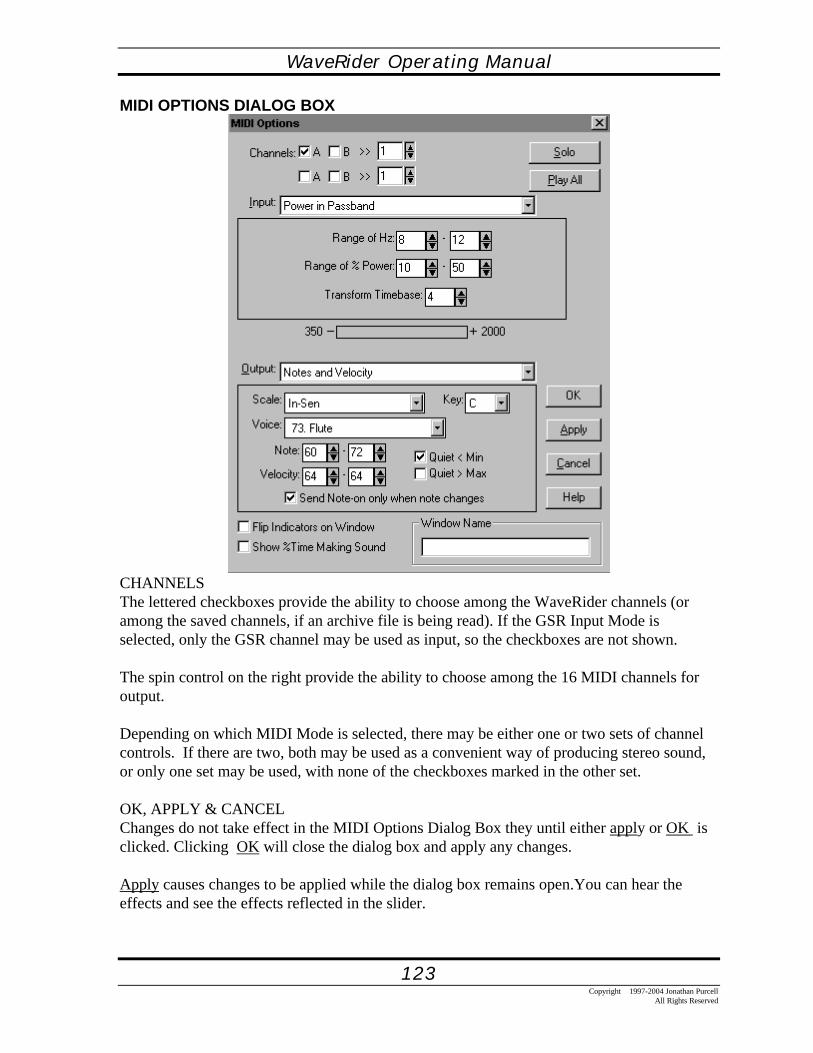
WaveRider Operating Manual
123Copyright 1997-2004 Jonathan Purcell
All Rights Reserved
MIDI OPTIONS DIALOG BOX
CHANNELSThe lettered checkboxes provide the ability to choose among the WaveRider channels (oramong the saved channels, if an archive file is being read). If the GSR Input Mode isselected, only the GSR channel may be used as input, so the checkboxes are not shown.
The spin control on the right provide the ability to choose among the 16 MIDI channels foroutput.
Depending on which MIDI Mode is selected, there may be either one or two sets of channelcontrols. If there are two, both may be used as a convenient way of producing stereo sound,or only one set may be used, with none of the checkboxes marked in the other set.
OK, APPLY & CANCELChanges do not take effect in the MIDI Options Dialog Box they until either apply or OK isclicked. Clicking OK will close the dialog box and apply any changes.
Apply causes changes to be applied while the dialog box remains open.You can hear theeffects and see the effects reflected in the slider.

WaveRider Operating Manual
124Copyright 1997-2004 Jonathan PurcellAll Rights Reserved
SLIDERThe slider in the middle of the dialog box is an important indicator of how well your inputsettings match the signal dynamics. The ends of the slider turn red when the signal exceedsthe settings in the current setup. The slider does not reflect the signal dynamics until theapply button is clicked. Clicking apply and observing the slider and sound output afterchanging settings is a good habit to develop.
QUIET < MINThe QUIET < MIN check box will cause the MIDI note to cease if the input value goesbelow the lower parameter. If not checked the last note will continue to play when the inputparameter goes out of range.
QUIET > MAXThe QUIET > MAX check box will cause the MIDI note to cease if the input value goesabove the upper parameter. If not checked the last note will continue to play when the inputparameter goes out of range.
SOLO & PLAY ALLSOLO mutes all MIDI voices except the voice being SOLOedPLAY ALL unmutes all muted voices.

WaveRider Operating Manual
125Copyright 1997-2004 Jonathan Purcell
All Rights Reserved
GENERAL GRAPHICS OPTIONS DIALOG BOX
CHANNELSThe checkboxes provide the ability to choose among the WaveRider channels (or among thesaved channels, if an archive file is being read.
If multiple channels are displayed in one window, those channels become Linked; the rangesof linked channels are always kept the same.
INPUTThe Input list box offers a choice among the parameters of biological signals from theWaveRider, which are then graphed. Which input mode is chosen will depend on the type ofbiological signal to be converted.
When an input mode is chosen, the controls within the large rectangle below the list box willchange to controls that are particular to the chosen mode:
TIME PER POINTEach point displayed in the General Graphics window represents the calculated parameterover a selected number of seconds, ranging from a quarter second up to 32 seconds. A longervalue allows the window to display the parameter over a longer period of time (up to severalhours), while a shorter value makes a momentary event more visible.

WaveRider Operating Manual
126Copyright 1997-2004 Jonathan PurcellAll Rights Reserved
GRIDYou may choose a grid indicating the value of the parameter being graphed, with or withoutthe numerical values along the left, or you may choose a totally plain display. You may alsochoose to add the time in seconds, along with a grid.
SPACINGThe default horizontal spacing uses one pixel per point. If x2 or x3 are selected, each pointuses correspondingly more space in the window, making less data visible at one time.
WINDOW NAMEIf desired, a name may be entered here which will be used in the window caption to identifythis General Graphics window. If a name is given, it will also be used in the ascii file if oneis created. Also, if another application is receiving data from WaveWare via DDE, thisname is used to identify that data.
This control is only used if another application is receiving data from WaveWare via DDE.If this option is checked, then the normalized value sent through DDE will be inverted,ranging from 1000 to 0 rather than 0 to 1000.

WaveRider Operating Manual
127Copyright 1997-2004 Jonathan Purcell
All Rights Reserved

WaveRider Operating Manual
128Copyright 1997-2004 Jonathan PurcellAll Rights Reserved
POWER IN PASSBAND
Power in Passband measures the amount of power in a user selected frequency band. It ishelpful for some people to think of a brainwave frequency band like a frequency band on theequalizer of a home stereo. Many stereos have a visual display of the spectral components ofthe audio output. This display generally has an array of leds. Each column of leds representsthe amount of power in one part of the audio spectrum. One end represents the high notes theother end the low notes and the middle bands the notes in between. In WaveWare Fast barsand Slow Bars show a similar break down in the brain wave frequency spectrum. Each barrepresents a one hertz frequency band.
The Power in Passband algorithm selects a specific portion of the brainwave spectrum. Thisis like looking at a single band on the equalizer of your stereo. The output is the amount ofpower in the selected frequency spectrum.
The sub-dialog box for power in passband is the same for the MIDI Options Dialog Box andthe general graphics options dialog box.

WaveRider Operating Manual
129Copyright 1997-2004 Jonathan Purcell
All Rights Reserved
There are three settings in the Power in Passband sub-dialog box, Range of Hz, Range of %Power, Transform timebase.
Range of Hz: Specifies the upper and lower edges of the frequency band. The numbersrepresents hertz or cycles per second.
The Range of % Power: sets the upper and lower bounds of power within the selectedfrequency band and is mapped to the MIDI, General Graph, ASCII and/or DDE output.. If theselected band is wider than the phenomena under consideration the event will be diluted. It isimportant to observe the slider, fast bars and slow bars to ascertain which frequencies areactually varying with the designated task.
The Transform Timebase: selects the rate of averaging in seconds for the time averagedfourier transform. A low number will give a faster response. A high number will smooth themoment to moment variability of the output.

WaveRider Operating Manual
130Copyright 1997-2004 Jonathan PurcellAll Rights Reserved
RATIO OF POWER IN PASSBAND
The Ratio of power in passband measures the ratio of power between two user selectedfrequency bands. Many neurotechnology protocols speak in terms of the ratio between twofrequency bands. (e.g. alpha-theta, beta-theta). These algorithms allow the user to raise onefrequency band while suppressing another band. This makes the output dependent on meetingtwo conditions one band high the other low. The frequency bands in question are the same asthose in power in passband.

WaveRider Operating Manual
131Copyright 1997-2004 Jonathan Purcell
All Rights Reserved
There are four set of settings in the Ratio of Power in Passband Sub-dialog box:
Hz Range A : sets the upper and lower bounds of the "A" frequency band. The numbersrepresents hertz or cycles per second.
Hz Range B: sets the upper and lower bounds of the "B" frequency band. The numbersrepresents hertz or cycles per second.
% Ratio of A/B: specifies the range of the ratio of power between the A and B frequencyrange that will be mapped to the MIDI, General Graph, ASCII and/or DDE output..
The Transform Timebase: selects the rate of averaging in seconds for the time averagedfourier transform. A low number will give a faster response. A high number will smooth themoment to moment variability of the output.

WaveRider Operating Manual
132Copyright 1997-2004 Jonathan PurcellAll Rights Reserved
DIGITAL FILTER
Digital Filter extracts certain frequencies out of the brainwave data. Which frequencies areselected depends on the filter used.
The names of each filter generally describe their frequency response.For example: 10-13_Hz-101 implements a 10 to 13 hertz 101 tap digital filter.

WaveRider Operating Manual
133Copyright 1997-2004 Jonathan Purcell
All Rights Reserved
There are three settings in the Digital Filter sub-dialog box:
Filter: Selects the frequency range of the digital filter to be used.
Range (uV): Defines the range of microvolts that will be mapped to the MIDI. GeneralGraphics, ASCII or DDE output.
mS: Defines the signal integration time in milliseconds. The default number of millisecondsis the reciprocal of the center frequency. A multiple of this number will give the bestresponse.

WaveRider Operating Manual
134Copyright 1997-2004 Jonathan PurcellAll Rights Reserved
RATIO OF TWO FILTERS
Ratio of Two Filters measures the relative amount of two frequency bands using digitalfilters. The ratio of the two bands is mapped to the output. These are the same frequencybands that are used in Digital Filter.

WaveRider Operating Manual
135Copyright 1997-2004 Jonathan Purcell
All Rights Reserved
There are five settings in the Ratio of Two Filters sub-dialog box:
Filter A: Selects the frequency range of the digital filter to be used.mS: Defines the signal integration time in milliseconds for filter A. The default number ofmilliseconds is the reciprocal of the center frequency. A multiple of this number will give thebest response.
Filter B: Selects the frequency range of the digital filter to be used.mS: Defines the signal integration time in milliseconds for filter B. The default number ofmilliseconds is the reciprocal of the center frequency. A multiple of this number will give thebest response.
% Ratio of A/B: specifies the range of the ratios between filters A and B frequency range thatwill be mapped to the MIDI, General Graph, ASCII and/or DDE output.

WaveRider Operating Manual
136Copyright 1997-2004 Jonathan PurcellAll Rights Reserved
REWARD/SUPPRESS RATIO
Reward/Suppress Ratio outputs the ratio of two digital filters (A and B), if certain conditionsare met. Filters A, B and C must be above or below user-specified threshholds to satisfy theconditions. If the conditions are not met than there is no output. Conditions may be turned onor off for each filter.
Typically the ratio of filter A to filter B will be used for the ratio of two brainwavefrequencies such as alpha/theta, beta/theta, or SMR/theta. Filter C is typically used to turn offaudio feedback in the event of either low or high frequency artifact.
Pictured above and on the facing page is a beta/theta protocol. When the ratio of beta to thetais between 60 and 130% MIDI notes 60 to 84 are output if the following conditions are met:Beta is above 2 uVolts,Theta is below 7uVolts,Delta is below 20 uVolts.

WaveRider Operating Manual
137Copyright 1997-2004 Jonathan Purcell
All Rights Reserved
Bands A, B and C each have the same settings.
Filter A, B or C: Selects the frequency range of the digital filter to be used.mS: Defines the signal integration time in milliseconds for filter A, B or C. The defaultnumber of milliseconds is the reciprocal of the center frequency. A multiple of this numberwill give the best response.uV: Defines the micro volt level of the threshold.Threshold Button: Controls how the threshold will be used. If "+" is displayed the conditionspecified is that the signal must be above the uV threshold. . If "-" is displayed the conditionspecified is that the signal must be below the uV threshold. If "0" is displayed the thresholdcondition is turned off for that filter band.
% Ratio of A/B: specifies the range of the ratios between filters A and B that will be mappedto the MIDI, General Graph, ASCII and/or DDE output if the conditions specified aresatisfied.

WaveRider Operating Manual
138Copyright 1997-2004 Jonathan PurcellAll Rights Reserved
REWARD/SUPPRESS
Reward/suppress outputs filter A if threshhold conditions for filters A and B are met.

WaveRider Operating Manual
139Copyright 1997-2004 Jonathan Purcell
All Rights Reserved
Filters A and B have the same settings.
Filter A or B: Selects the frequency range of the digital filter to be used.mS: Defines the signal integration time in milliseconds for filter A or B. The default numberof milliseconds is the reciprocal of the center frequency. A multiple of this number will givethe best response.uV: Defines the micro volt level of the threshold.Threshold Button: Controls how the threshold will be used. If "+" is displayed the conditionspecified is that the signal must be above the uV threshold. . If "-" is displayed the conditionspecified is that the signal must be below the uV threshold. If "0" is displayed the thresholdcondition is turned off for that filter band.
Range uV: specifies the range of uVolts from filter A that will be mapped to the MIDI,General Graph, ASCII and/or DDE output if the conditions specified are satisfied.

WaveRider Operating Manual
140Copyright 1997-2004 Jonathan PurcellAll Rights Reserved
DOMINANT FREQUENCY
Dominant Frequency measures the dominant frequency of the selected range of brainwavefrequencies, i.e. the frequency in the selected range that has the most power. The FFT is thesource for the frequency information. Dominant frequency can be used in two ways. It canmeasure gross trends of brainwave frequency within a session. Alternatively it can also beused to measure gradual relocation of frequencies within a particular band. As an example ofthe latter, it is observed that meditaters tend to produce a downshift in the dominant alphafrequency the longer they meditate (usually measured in years). Power in Passband and Ratioof Power in Passband are generally more useful indicators of states of consciousness.

WaveRider Operating Manual
141Copyright 1997-2004 Jonathan Purcell
All Rights Reserved
There are two settings in the Dominant Frequency sub-dialog box.
Range of Hz to Scan: Selects the range of frequencies from which the dominant frequency isdetermined. It also sets the range of hertz that will be mapped to the upper and lower boundsof the MIDI, General Graph, ASCII and/or DDE output. The numbers represents hertz orcycles per second.
The Transform Timebase: selects the rate of scanning in seconds for the time averagedfourier transform. A low number will give a faster response. A high number will smooth themoment to moment variability of the output.
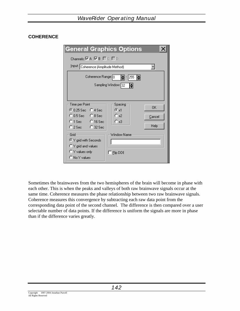
WaveRider Operating Manual
142Copyright 1997-2004 Jonathan PurcellAll Rights Reserved
COHERENCE
Sometimes the brainwaves from the two hemispheres of the brain will become in phase witheach other. This is when the peaks and valleys of both raw brainwave signals occur at thesame time. Coherence measures the phase relationship between two raw brainwave signals.Coherence measures this convergence by subtracting each raw data point from thecorresponding data point of the second channel. The difference is then compared over a userselectable number of data points. If the difference is uniform the signals are more in phasethan if the difference varies greatly.

WaveRider Operating Manual
143Copyright 1997-2004 Jonathan Purcell
All Rights Reserved
There are three settings in the Coherence Sub-dialog box.
Coherence Range: Selects the range of Coherence (from 0-255) that will be mapped to theupper and lower bounds of the MIDI, General Graph, ASCII and/or DDE output.
Sampling Window: Selects the number of raw data points of which the signal is compared.
Sampling Interval(MIDI only): Sets how often MIDI notes are output. The numberrepresents how many data points have to be collected before a note is output. A highernumber means more time between notes.

WaveRider Operating Manual
144Copyright 1997-2004 Jonathan PurcellAll Rights Reserved
HEART RATE
The Heart Rate Input measures the heart rate in beats per minute. There are three choicesfrom the Heart Menu: Strip chart, General Graph and Heart Rate.
1. Strip Chart displays the raw signal.2. General Graph allows you to output the heart rate as a general graph, a post session
ASCII output or a live DDE output.3. Heart Rate is a digital display of the heart rate.
It is important to have a good artifact free signal when using Heart Rate or it will not beaccurate.. Measuring the heart rate across the chest is usually best. It is interesting to noteboth the variability between individuals as well as the moment to moment variation of thesame individual.

WaveRider Operating Manual
145Copyright 1997-2004 Jonathan Purcell
All Rights Reserved
Beats to Average: specifies how many beats to average for each reading. A high number willsmooth out the beat to beat variability.
Rate (beats/min): Set the range of Heart Rate that forms the upper and lower bounds of theMIDI note range, General Graph display or DDE output.
Display Tenths: If turned on, displays the Heart Rate in units of tenths of heart beat perminute.

WaveRider Operating Manual
146Copyright 1997-2004 Jonathan PurcellAll Rights Reserved
GSR
GSR measures the conductivity of the skin. This varies with the level of arousal of theautonomic nervous system. The GSR works by passing a minute amount of current throughthe body (<10 micro Amps). Although in reality more complicated, it is easiest to think of theGSR in terms of sweaty palms. When you are nervous or stressed your palms sweat. Thisraises the conductivity of your skin (makes it easier for electricity to pass through it). Whenyou are calm you sweat less and hence are less conductive.
There are three choices from the GSR Menu: Graph, Meter and General Graph .
1. Graph displays the raw signal.2. General Graph allows you to output the GSR as a general graph, a post session ASCII
output or a live DDE output.3. Meter is a digital display of the GSR.

WaveRider Operating Manual
147Copyright 1997-2004 Jonathan Purcell
All Rights Reserved
The GSR Sub-Dialog Box has one setting and one special button.
Range of GSR: Sets the range of GSR values that will be mapped to the upper and lowerbounds of the MIDI, General Graph, ASCII and/or DDE output.
Copy from GSR Chart: Copies the uper and lower bounds of the GSR Graph into eitherGeneral Graphics or MIDI. Copying of GSR may need to be done several times during asession with widely varying GSR.

WaveRider Operating Manual
148Copyright 1997-2004 Jonathan PurcellAll Rights Reserved
PEAK TO PEAK AMPLITUDE
Peak to Peak Amplitude measure the envelope or power of a muscle contraction. It can beused to measure relaxation or play music with your muscles.

WaveRider Operating Manual
149Copyright 1997-2004 Jonathan Purcell
All Rights Reserved
There are three settings in the Peak-to-Peak Amplitude sub dialog box.
Amplitude Range: Sets the range of power that will be mapped to the upper and lowerbounds of the MIDI, General Graph, ASCII and/or DDE output.
Sampling Window: Sets the number of raw data points over which Peak-to-Peak Amplitudeinput is processed.
Sampling Interval: Sets how often MIDI notes are output. The number represents how manydata points have to be collected before a note is output. A higher number means more timebetween notes.

WaveRider Operating Manual
150Copyright 1997-2004 Jonathan PurcellAll Rights Reserved
NEUROSCIENCE: THE GENERATION OF BRAINWAVES
THE AUTONOMIC NERVOUS SYSTEMThe autonomic nervous system controls arousal . It consists of the sympathetic (fight orflight) and para-sympathetic (rest and digest) systems. It is not part of the central nervoussystem but forms a separate "visceral" system. The autonomic and central nervous systemcommunicate primarily through the hypothalamus which also controls the pituitary, themaster gland of the endocrine system.
The GSR reflects the level of arousal of the autonomic nervous system. Decreased arousalreflects a stimulation of the para-sympathetic system and inhibition of the sympatheticsystem. .
The sympathetic system tends to have a much faster onset than the para-sympathetic. Whenyou are threatened and get an "adrenaline rush" your body responds quickly. The relaxationresponse after the threat is removed tends to be much slower. This is reflected in the GSR.When you stress yourself the slope of the GSR is much steeper than the relaxation curve afterthe stressful event.
The key features of the autonomic nervous system are ganglia, where many nerve cells cometogether. In the sympathetic nervous system these ganglia are situated on either side of thespinal column in the thoracic and upper lumbar region. In the para-sympathetic system theganglia are located in the organs which their cells connect to. Both systems can be inhibitedor stimulated. They will in turn inhibit or stimulate the organs with which they are connected.It is to be noted though that a stimulation of one autonomic system may cause an inhibition ofthe organ in question. When both systems innervate an organ they are usually opposed intheir actions. For instance, stimulating the sympathetic system will increase the heart rate.Stimulating the para-sympathetic system will decrease the heart rate.
The sympathetic system if stimulated will cause thepupils to dilate,sweating to increase,heart rate to increase,force of contraction of the heart to increase,pulmonary bronchi to dilate,pulmonary blood vessels to mildly constrictperistalsis to decreasesphincter to constrictkidney to decrease its outputbasal metabolism to increaseskeletal muscles to increase strengthblood coagulation to increase.
These are all actions that prepare the body for fight or flight
The para-sympathetic system if stimulated causes the:

WaveRider Operating Manual
151Copyright 1997-2004 Jonathan Purcell
All Rights Reserved
pupils to dilatenose to runheart rate to decreaseforce of contraction of the heart to decreasebronchi to constrictperistalsis to increaseurine output to increase.
These are all rest and digest responses.
THE BRAINThe human brain has two hemispheres, three meninges and four lobes. The hemispheres arethe right and left halves of the brain connected through the corpus callosum. The threemeninges are the protective layers around the brain. The four lobes are the frontal, parietal,occipital and temporal. Each of these will be described below.
The brain is a bi-laterally symmetrical organ, i.e. it is composed of two hemispheres that are(with a few exceptions) mirror images of each other. In general each hemisphere controls theopposite side of the body. Split brain studies which were done by severing the corpuscallosum connecting the two hemispheres in severely epileptic patients, provided a wealth ofinformation on the function of each hemisphere. The left brain controls the right side of thebody and is more prevalent in logical thinking, mathematics, verbal and analytical skills Theright brain controls the left side of the body and is more prevalent in spatial tasks, synthetic,aesthetic and gestalt type thinking.
In the 1970's there was much popular writing concerning the two hemispheres of the brain.Since that time information has accumulated that calls into question the simplicity of some ofthe models then proposed. In fact, both hemispheres interact considerably in most complextasks. It is wrong to think of the two halves of the brain as separate systems. They areintricately linked with one another and work together in most tasks. Indeed, if one side of thebrain is damaged at birth, quite often the other will take over its' functions.
The brain is bathed in cerebrospinal fluid. There are three layers of protection around thebrain, the so-called meninges. The most external of these, the DURA MATER (which means"tough mother") is a thick tough layer of tissue adhered to the inside of the skull. The nextlayer the ARACHNOID is named for its spider web like appearance. It has cerebrospinalfluid circulating beneath it in the sub-ARACHNOID space. The PIA MATER is a thin layerthat adheres to the brain.
The frontal lobe is the largest of the four lobes of the cerebellum. It has an especially richconnection with the limbic system. It is primarily involved in planning, decision making, andpurposeful behavior. The rolandic fissure separates the frontal lobe from the parietal lobe. Onthe frontal side of the rolandic fissure is the motor cortex that directs the volitional control ofthe musculoskeletal system.

WaveRider Operating Manual
152Copyright 1997-2004 Jonathan PurcellAll Rights Reserved
On the parietal side of the rolandic fissure lies the sensory cortex which receives informationabout body position, muscles, touch and pressure from all over the body.
The temporal lobe is involved in hearing, perception and memory. It also plays a part inlanguage.
The occipital lobe is involved in vision. The primary visual cortex is at the extreme posteriorof the occipital lobe.
Located between the cerebral hemispheres and above the brain stem are several veryimportant "deep" brain structures. The Limbic system, the thalamus and the basal ganglia.
The limbic system consists of the hippo campus, hypothalamus and amygdala. The limbicsystem regulates homeostasis, or the maintenance of constant body temperature, bloodpressure, heart rate, blood sugar levels etc.. The hypothalamus does this through itsconnections to the autonomic nervous system. In addition, the hypothalamus controls thepituitary gland which in turn is the master gland of the endocrine system. The hippocampus isinvolved in memory storage. The amygdala coordinates the autonomic and endocrine systemsand is involved in emotions.
The basal ganglia are located on either side of the limbic system. They consist of five bi-laterally paired structures: the caudate nucleus, putamen, globus pallidus, sub thalamicnucleus and substantia nigra. They are concerned with movement control, in particularinitiating movements. Unlike other parts of the movement system the basal ganglia do notconnect to the spinal cord but to the cortex by way of the thalamus.
Many neural pathways pass through the thalamus. Indeed, the thalamus is a crossroads formost of the sensory and motor information that is relayed to the cerebral cortex. In addition, ithelps to initiate consciousness and make preliminary classifications of external events.Thalamo-cortical pathways are thought to account for much of the rhythmicity seen inbrainwaves. Alpha waves rhythms are initiated in the thalamus and radiated to the cerebralcortex.

WaveRider Operating Manual
153Copyright 1997-2004 Jonathan Purcell
All Rights Reserved
BRAINWAVE GENERATIONBrainwaves typically range from 20-100 micro Volts and from 1-50 Hertz.
Alpha waves 8-12 Hertz are associated with a state of relaxed wakefulness. They are bestrecorded over the occipital and parietal lobes. Quite often alpha waves can be generated bysimply closing the eyes.
Beta waves12-18 Hertz are normally seen over the frontal regions and over the other regionsduring intense mental activity.
Theta waves 4-8 Hz normally appear first over the frontal regions of the brain. They areusually seen when one is falling asleep.
Brainwaves are generated in the cortex by the flow of synaptic currents through the extra-cellular space. Electrical activity of pyramidal cells is the principal source of brainwaves.Pyramidal cells are so named because of the shape of the cell body. They often cross severallayers in the cortex and their dendrites are always oriented perpendicular to the surface of thecortex.
Most potentials recorded from the scalp are the result of extra-cellular current flow associatedwith the summated synaptic potentials in the activated pyramidal cells. Since pyramidal cellsare oriented parallel to one another and perpendicular to the surface of the cortex theirelectrical sources and sinks do not cancel each other out and can be summed, thus creating ameasurable potential.

WaveRider Operating Manual
154Copyright 1997-2004 Jonathan PurcellAll Rights Reserved
APPENDICES
WHAT IS DDE AND THE DDE SDK?The WaveRider DDE SDK consists of WWDDE.DLL and its associated header file andexport library. Functions within the DLL allow a Windows application to easily establish aDDE link with WaveWare, over which the application can obtain data from WaveWare eitherthrough callback functions (DDE hot links) or by query (DDE cold links). Additionally, theapplication can execute WaveWare before linking with it, close WaveWare when it isfinished, and perform a variety of control functions which affect WaveWare's operation.
Using WWDDE.DLL, a single application can connect with multiple instances of WaveWare(which in turn operate WaveRiders on separate serial ports). Multiple applications cansimultaneously connect to a single instance of WaveWare. In the future, links may be able tobe established over a network, using the NetDDE protocol under Windows 95.
The philosophy guiding the design of this SDK points to the creation of a very simple, easy-to-use interface to WWDDE.DLL. In order to create a system involving biological signals,the configuration of WaveWare itself must be created. For example, WWDDE.DLL makes iteasy to connect with WaveWare's General Graphics windows, but the DLL does not providefor configuring of those windows. If it did, the DLL and SDK would be extremelycomplex, and would change continually as WaveWare grew. Our philosophy is to avoid this,giving developers a robust, powerful interface which can be learned in a short time and usedon a high level.
At present most of the data links with WaveWare are implemented as DDE (Dynamic DataExchange) conversations, with WaveWare as the server and WWDDE.DLL as the client.While it would be possible for an application to bypass WWDDE.DLL and create its ownDDE conversation with WaveWare, this is not recommended. First, DDE is not a trivialexercise, and a great deal of bookkeeping and error handling is provided by WWDDE.DLL.Second, the DDE protocol used by WaveWare is not published, and is subject to change,while the DLL shields the application from this protocol. Third, DDE may not be the onlyform of interprocess communication to be used in the future, as both WaveWare andWindows continue to evolve.