WaveLinx WCL Installation Instructions WaveLinx Wireless ......WaveLinx WCL Installation...
12
WaveLinx (WCL) Installation Instructions WaveLinx Wireless Area Controller (WAC) Wireless Area Controller SAFETY INSTRUCTIONS IMPORTANT SAFEGUARDS READ AND FOLLOW ALL SAFETY INSTRUCTIONS ● ● Installation should be performed by a qualified electrician ● ● Installation shall be in accordance with all applicable local and NEC codes ● ● Turn the power off at circuit breakers before wiring ● ● Designed for indoor installation and use only ● ● All new wiring must be fully verified before applying power ● ● Servicing of equipment should be performed by qualified service personnel Read all of the instructions thoroughly before installing or operating this product. This manual provides information on the installation and operation of the WaveLinx Wireless Area Controller (WAC). For proper operation it is important to follow the instructions.
Transcript of WaveLinx WCL Installation Instructions WaveLinx Wireless ......WaveLinx WCL Installation...

INS #
Brand Logo reversed out of black
INS #WaveLinx (WCL) Installation Instructions
WaveLinx Wireless Area Controller (WAC)
Wireless Area Controller
SAFETY INSTRUCTIONSIMPORTANT SAFEGUARDS
READ AND FOLLOW ALL SAFETY INSTRUCTIONS
●● Installation should be performed by a qualified electrician
●● Installation shall be in accordance with all applicable local and NEC codes
●● Turn the power off at circuit breakers before wiring
●● Designed for indoor installation and use only
●● All new wiring must be fully verified before applying power
●● Servicing of equipment should be performed by qualified service personnel
Read all of the instructions thoroughly before installing or operating this product.This manual provides information on the installation and operation of the WaveLinx Wireless Area Controller (WAC). For proper operation it is important to follow the instructions.
2 EATON IB053008EN Installation instructions
WaveLinx Wireless Area Controller (WAC)
SAVE THESE INSTRUCTIONSThis installation instruction is for the Wireless Area Controller (WAC-POE) which enables user control of the WaveLinx system and devices via local control or through the WaveLinx Mobile application.
The purpose of this document is to provide sufficient detailed instructions for installation and basic troubleshooting.
This document covers installation of the following products.●● WAC-POE Wireless Area Controller, POE powered
●● WAC-120 Wireless Area Controller, 120V (includes PoE injector for power)
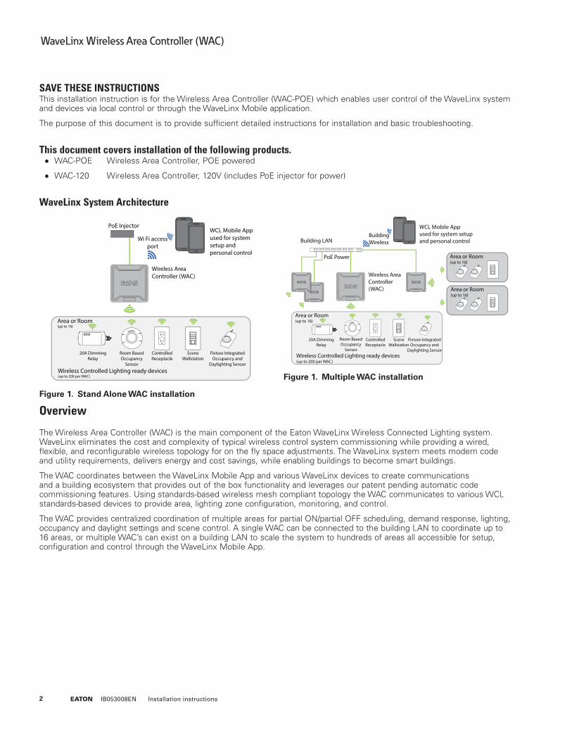
WaveLinx System Architecture
Figure 1. Stand Alone WAC installation
Figure 1. Multiple WAC installation
Overview
The Wireless Area Controller (WAC) is the main component of the Eaton WaveLinx Wireless Connected Lighting system. WaveLinx eliminates the cost and complexity of typical wireless control system commissioning while providing a wired, flexible, and reconfigurable wireless topology for on the fly space adjustments. The WaveLinx system meets modern code and utility requirements, delivers energy and cost savings, while enabling buildings to become smart buildings.
The WAC coordinates between the WaveLinx Mobile App and various WaveLinx devices to create communications and a building ecosystem that provides out of the box functionality and leverages our patent pending automatic code commissioning features. Using standards-based wireless mesh compliant topology the WAC communicates to various WCL standards-based devices to provide area, lighting zone configuration, monitoring, and control.
The WAC provides centralized coordination of multiple areas for partial ON/partial OFF scheduling, demand response, lighting, occupancy and daylight settings and scene control. A single WAC can be connected to the building LAN to coordinate up to 16 areas, or multiple WAC’s can exist on a building LAN to scale the system to hundreds of areas all accessible for setup, configuration and control through the WaveLinx Mobile App.

3EATON IB053008EN Installation instructions
WaveLinx Wireless Area Controller (WAC)
WaveLinx system components●● Wireless Area Controller (Gateway)
●● WaveLinx Mobile App (Commissioning and user personal control)
●● WaveLinx Wallstation (Manual lighting and scene control)
●● Wireless INstinct Sensor (Fixture integrated occupancy sensor, ambient light sensor and control)
●● WaveLinx Relay Switchpack with 0-10V
●● WaveLinx Receptacle (Wall mounted power outlet)
●● WaveLinx Room Based Sensor (Ceiling mounted PIR occupancy sensor)
Wireless Area Controller
4 EATON IB053008EN Installation instructions
WaveLinx Wireless Area Controller (WAC)
Installation
The Wireless Area Controller (WAC) must be installed in accordance with all local, state, and national electrical codes and requirements. Before mounting the WAC in its final location:
1. Install Wavelinx wireless devices and verify out-of-the-box functionality
2. Mount the Wireless Area Controller (WAC)
●● Ensure the WAC is roughly in the center of the spaces and devices it is communicating to.
●● Review the “Where to Mount” section of this installation instruction.
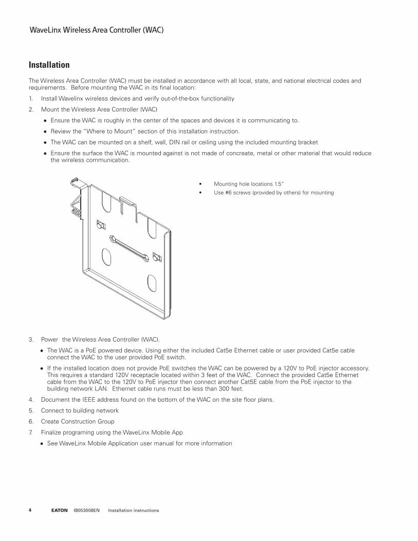
●● The WAC can be mounted on a shelf, wall, DIN rail or ceiling using the included mounting bracket
●● Ensure the surface the WAC is mounted against is not made of concreate, metal or other material that would reduce the wireless communication.
• Mounting hole locations 1.5”
• Use #6 screws (provided by others) for mounting
3. Power the Wireless Area Controller (WAC).
●● The WAC is a PoE powered device. Using either the included Cat5e Ethernet cable or user provided Cat5e cable connect the WAC to the user provided PoE switch.
●● If the installed location does not provide PoE switches the WAC can be powered by a 120V to PoE injector accessory. This requires a standard 120V receptacle located within 3 feet of the WAC. Connect the provided Cat5e Ethernet cable from the WAC to the 120V to PoE injector then connect another Cat5E cable from the PoE injector to the building network LAN. Ethernet cable runs must be less than 300 feet.
4. Document the IEEE address found on the bottom of the WAC on the site floor plans.
5. Connect to building network
6. Create Construction Group
7. Finalize programing using the WaveLinx Mobile App
●● See WaveLinx Mobile Application user manual for more information

5EATON IB053008EN Installation instructions
WaveLinx Wireless Area Controller (WAC)
Where to Mount the WAC●● Typically installed above the drop ceiling or high on the wall in the center of the space it will be controlling
●● The WAC should be located so it has a good line-of-sight view of devices it will be communicating to.
●● Within 300ft of the PoE switch or building LAN connection point
●● At least 10 feet away from the building WiFi access points
●● At least 15 feet away from concreate or metal structures
Where NOT to Mount the WAC●● Inside a metal enclosure or near large metal objects or walls
●● Inside or near large concreate walls or spaces
●● Do not mount inside electrical closet
WaveLinx design best practices
Design Consideration Best Practice Maximum Capability
Gateway/WAC Range 150 feet-250 feet LOS (no walls) 300 feet LOS
Number of Interior Walls 2 walls 3 walls
Distance from WAC to 1st WCL Device 150 feet 200 feet
Distance between WCL Devices 75 feet 150 feet
Number of Hops from WAC 4 hops 5 hops
Number of Areas per WAC 16 16
Number of Zones per Area 3 16
Number of Scenes per Area 6 10
Wireless Area Controller LED Indicators
The LED indicators can be used for diagnostics and troubleshooting diagnostics of the WaveLinx system. The table below gives you more information.

6 EATON IB053008EN Installation instructions
WaveLinx Wireless Area Controller (WAC)
LED Color On Off Blink Fast Blink
WAN Green Connection to OpenADR or 3rd party
Normal Communications from 3rd party
LAN Green Connected to building LAN and received IP address
No connection or IP address from building LAN
Communications from LAN.
During internal webpage setup
WiFi Blue Connected to building LAN and received IP address
No connection or IP address from building LAN
Communications from LAN.
During internal webpage setup
When login UN/PW are reset
PAN Blue Future functionality Future functionality Future functionality Future functionality
802.15.4 Blue WaveLinx network is formed
No WaveLinx devices are paired
During Construction Grouping and WaveLinx
Communications
When WAC is set to Factory Defaults
Eaton Blue WAC is powered and running
WAC has no PoE connection
Wireless Area Controller rear panel
●● Ethernet Port for power in and connection to building LAN for communications.
●● PoE is required to supply power to the device
●● PoE port does not supply power out to other devices
●● RESET Button
●● Resets the Wireless Area Controller, does not impact settings
●● PAIR Button
●● Construction Group
●● Removing devices
●● Reset login UN/PW
●● Factory Defaults
7EATON IB053008EN Installation instructions
WaveLinx Wireless Area Controller (WAC)
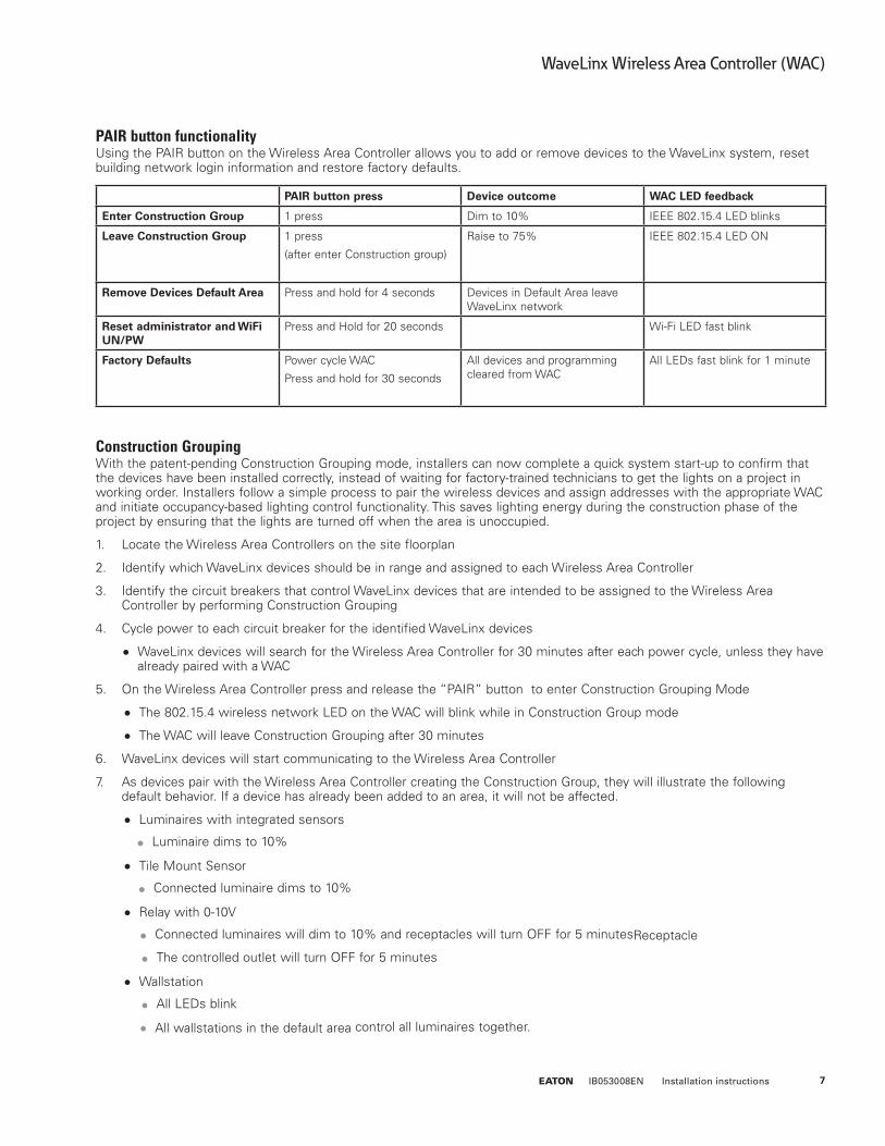
PAIR button functionalityUsing the PAIR button on the Wireless Area Controller allows you to add or remove devices to the WaveLinx system, reset building network login information and restore factory defaults.
Construction GroupingWith the patent-pending Construction Grouping mode, installers can now complete a quick system start-up to confirm that the devices have been installed correctly, instead of waiting for factory-trained technicians to get the lights on a project in working order. Installers follow a simple process to pair the wireless devices and assign addresses with the appropriate WAC and initiate occupancy-based lighting control functionality. This saves lighting energy during the construction phase of the project by ensuring that the lights are turned off when the area is unoccupied.
1. Locate the Wireless Area Controllers on the site floorplan
2. Identify which WaveLinx devices should be in range and assigned to each Wireless Area Controller
3. Identify the circuit breakers that control WaveLinx devices that are intended to be assigned to the Wireless Area Controller by performing Construction Grouping
4. Cycle power to each circuit breaker for the identified WaveLinx devices
●● WaveLinx devices will search for the Wireless Area Controller for 30 minutes after each power cycle, unless they have already paired with a WAC
5. On the Wireless Area Controller press and release the “PAIR” button to enter Construction Grouping Mode
●● The 802.15.4 wireless network LED on the WAC will blink while in Construction Group mode
●● The WAC will leave Construction Grouping after 30 minutes
6. WaveLinx devices will start communicating to the Wireless Area Controller
7. As devices pair with the Wireless Area Controller creating the Construction Group, they will illustrate the following default behavior. If a device has already been added to an area, it will not be affected.
●● Luminaires with integrated sensors
●● Luminaire dims to 10%
●● Tile Mount Sensor
●● Connected luminaire dims to 10%
●● Relay with 0-10V
●● Connected luminaires will dim to 10% and receptacles will turn OFF for 5 minutesReceptacle
●● The controlled outlet will turn OFF for 5 minutes
●● Wallstation
●● All LEDs blink
●● All wallstations in the default area control all luminaires together.
PAIR button press Device outcome WAC LED feedback
Enter Construction Group 1 press Dim to 10% IEEE 802.15.4 LED blinks
Leave Construction Group 1 press
(after enter Construction group)
Raise to 75% IEEE 802.15.4 LED ON
Remove Devices Default Area Press and hold for 4 seconds Devices in Default Area leave WaveLinx network
Reset administrator and WiFi UN/PW
Press and Hold for 20 seconds Wi-Fi LED fast blink
Factory Defaults Power cycle WAC
Press and hold for 30 seconds
All devices and programming cleared from WAC
All LEDs fast blink for 1 minute

8 EATON IB053008EN Installation instructions
WaveLinx Wireless Area Controller (WAC)
8. After all WaveLinx devices have joined the Construction Group and illustrated the above behavior.
●● Press the “PAIR” button on the WAC a second time to leave the Construction Grouping mode,
●● The WAC will leave Construction Grouping automatically after 30 minutes if the “PAIR” button is not pressed a second time.
●● The IEEE 802.15.4 wireless network LED on the WAC will be ON
9. After leaving the Construction Group mode the WaveLinx devices will behave in the following manner.
●● Luminaires with integrated sensors
●● Luminaire dims to 75%
●● All luminaires turn ON when the first occupancy sensor senses motion
●● All luminaires turn OFF when the last occupancy sensor times out unoccupied
●● All wallstations in the default area control all luminaires together.
●● All integrated sensors, Tile Mount and Ceiling sensors create an occupancy group
●● Tile Mount Sensor.
●● Connected luminaire dims to 75%
●● All luminaires turn ON when the first occupancy sensor senses motion
●● All luminaires turn OFF when the last occupancy sensor times out unoccupied
●● All wallstations in the default area control all luminaires together.
●● All integrated sensors, Tile Mount and Ceiling sensors create an occupancy group
●● Relay with 0-10V
●● Connected luminaires dim to 75%
●● All wallstations in the default area control all luminaires together.
●● All luminaires turn ON when the first occupancy sensor senses motion
●● All luminaires turn OFF when the last occupancy sensor times out unoccupied
●● Relay turns ON/OFF based on occupancy
●● Receptacle
●● The controlled outlet will turn ON/OFF based on occupancy
●● Wallstation
●● All wallstations in the default area will control all luminaires in the default area based on out-of-the-box scene definitions.
●● Ceiling Sensor
●● The LED on the sensor will flash when detecting occupancy
●● All integrated sensors, Tile Mount and ceiling sensors create an occupancy group
Connecting the Wireless Area Controller to the Building LAN1. Wired Connection - Building LAN connection
●● Connect the WAC to the building PoE switch or PoE injector into the normal network.
●● Physical connection to the building LAN and receiving an IP address will automatically disable the wireless connection method
●● WAC’s will automatically receive a DHCP IP address when connected to the building LAN
●● WAC device name will be: Eaton-xxxxxxxxxxxx on the building network
●● (where **** are all twelve characters of the unit MAC address found on the label at the bottom front of the WAC plus 1)

9EATON IB053008EN Installation instructions
WaveLinx Wireless Area Controller (WAC)
●● Using the WAC internal web page,
●● Change the default name of the WAC
●● Statically assigning the IP address of the WAC
2. Wireless Connection - Building Wireless connection
●● WAC device name will be: Eaton-xxxxxxxxxxxx
●● (where **** are all twelve characters of the unit MAC address found on the label at the bottom front of the WAC plus 1)
●● Using the WAC internal web page,
●● Enter the building wireless login credentials.
●● Building wireless login credentials are secured in the WAC by secure web pages and encryption during storage.
●● Change the default name of the WAC
●● Statically assigning the IP address of the WAC
THIS DEVICE COMPLIES WITH PART 15 OF THE FCC RULES. OPERATION IS SUBJECT TO THE FOLLOWING TWO
CONDITIONS:
1. THIS DEVICE MAY NOT CAUSE HARMFUL INTERFERENCE
2. THIS DEVICE MUST ACCEPT
This device complies with Industry Canada™s licence-exempt RSSs. Operation is subject to the following two conditions:
1. This device may not cause interference; and
2. This device must accept any interference, including interference that may cause undesired operation of the device.
Le présent appareil est conforme aux CNR d™Industrie Canada applicables aux appareils radio exempts de licence. L™exploitation est
Autorisée aux deux conditions suivantes:
1. l™appareil ne doit pas produire de brouillage, et
2. l™utilisateur de l™appareil doit accepter tout brouillage radioélectrique subi, même si le brouillage est susceptible d™en compromettre le fonctionnement.
To maintain compliance with the RF exposure guidelines, place the unit at least 20cm from nearby persons.
Pour assurer la conformité aux directives relatives à l’exposition aux frequencies radio, le jouet doit êtreplacé à au moins 20_cm des personnes à proximité.
Any changes or modifications not expressly approved by the party responsible for compliance could void the user’s authority to operate this equipment.

10 EATON IB053008EN Installation instructions
WaveLinx Wireless Area Controller (WAC)

11EATON IB053008EN Installation instructions
WaveLinx Wireless Area Controller (WAC)
Eaton1121 Highway 74 SouthPeachtree City, GA 30269P: 770-486-4800www.eaton.com/lighting
Canada Sales 5925 McLaughlin RoadMississauga, Ontario L5R 1B8P: 905-501-3000F: 905-501-3172
© 2017 EatonAll Rights ReservedPrinted in USAImprimé aux États-UnisImpreso en los EE. UU.Publication No. IB053008EN February 16, 2017
Eaton is a registered trademark.All trademarks are property of their respective owners.
Eaton est une marque de commercedéposée. Toutes les autres marques de commerce sont la propriété de leur propriétaire respectif.
Eaton es una marca comercialregistrada. Todas las marcas comerciales son propiedad de sus respectivos propietarios.
Product availability, specifications, and compliances are subject to change without notice.
La disponibilité du produit, les spécifications et les conformités peuvent être modifiées sans préavis.
La disponibilidad de productos, las especificaciones y los cumplimientos están sujetos a cambio sin previo aviso.
Warranties and Limitation of LiabilityPlease refer to www.eaton.com/LightingWarrantyTerms for our terms and conditions.
Garanties et limitation de responsabilitéVeuillez consulter le site www.eaton.com/LightingWarrantyTerms pour obtenir les conditions générales.
Garantías y Limitación de ResponsabilidadVisite www.eaton.com/LightingWarrantyTerms para conocer nuestros términos y condiciones.