Wave front dispersion due to fluid-structure interaction ... · hydraulic transients with...
22
ACCEPTED VERSION Tijsseling, Arris Sieno; Lambert, Martin Francis; Simpson, Angus Ross; Stephens, Mark Leslie; Vitkovsky, John; Bergant, Anton Skalak's extended theory of water hammer Journal of Sound and Vibration, 2008; 310 (3):718-728 Copyright © 2007 Elsevier http://hdl.handle.net/2440/46757 PERMISSIONS http://www.elsevier.com/journal-authors/author-rights-and-responsibilities#author- posting How authors can post their articles online Author posting Voluntary posting on open web sites operated by author or author's institution for scholarly purposes. Accepted Author Manuscript (AAM) Definition: An accepted author manuscript (AAM) is the author's version of the manuscript of an article that has been accepted for publication and which may include any author-incorporated changes suggested through the processes of submission, peer review and editor-author communications. AAMs do not include other publisher value-added contributions such as copy-editing, formatting, technical enhancements and (if relevant) pagination. 18 March 2014
Transcript of Wave front dispersion due to fluid-structure interaction ... · hydraulic transients with...

ACCEPTED VERSION
Tijsseling, Arris Sieno; Lambert, Martin Francis; Simpson, Angus Ross; Stephens, Mark Leslie; Vitkovsky, John; Bergant, Anton Skalak's extended theory of water hammer Journal of Sound and Vibration, 2008; 310 (3):718-728
Copyright © 2007 Elsevier
http://hdl.handle.net/2440/46757
PERMISSIONS
http://www.elsevier.com/journal-authors/author-rights-and-responsibilities#author-posting
How authors can post their articles online
Author posting
Voluntary posting on open web sites operated by author or author's institution for scholarly purposes.
Accepted Author Manuscript (AAM) Definition: An accepted author manuscript (AAM) is the author's version of the manuscript of an article that has been accepted for publication and which may include any author-incorporated changes suggested through the processes of submission, peer review and editor-author communications. AAMs do not include other publisher value-added contributions such as copy-editing, formatting, technical enhancements and (if relevant) pagination.
18 March 2014
1
Skalak’s extended theory of water hammer
Arris S. TIJSSELING * corresponding author
Department of Mathematics and Computer Science
Eindhoven University of Technology
Den Dolech 2
P.O. Box 513, 5600 MB Eindhoven, The Netherlands
Phone: +31 40 247 2755; Fax: +31 40 244 2489; Email: [email protected]
Martin F. LAMBERT, Angus R. SIMPSON, Mark L. STEPHENS
Water Systems Research Group
School of Civil and Environmental Engineering
University of Adelaide
Adelaide, Australia 5005
Phone: +61 8 8303 5135; Fax: +61 8 8303 4359; Emails:
John P. VÍTKOVSKÝ
Water Assessment Group
Department of Natural Resources and Water
Queensland Government
Indooroopilly QLD 4068, Australia
Email: [email protected]
Anton BERGANT
Litostroj E.I. d.o.o.
Litostrojska 50
1000 Ljubljana, Slovenia
Phone: +386 1 5824 284; Fax: +386 1 5824 174; Email: [email protected]

2
Abstract
Half a century ago Richard Skalak [1] published a paper with the title "An extension of the
theory of water hammer" [24], which has been the basis of much subsequent work on
hydraulic transients with fluid-structure interaction (FSI). The paper considers the propagation
of pressure waves in liquid-filled pipes and the coupled radial/axial response of the pipe walls.
In a tribute to Skalak's work, his paper is revisited and some of his less-known results are used
to assess the dispersion of pressure waves in long-distance pipelines. Skalak’s theory predicts
that the spreading of wave fronts due to FSI is small, at most of the order of ten pipe
diameters.
Key words: Pipelines; Hydraulic transients; Pressure surges; Fluid-structure interaction;
Wave front dispersion; Precursor wave.

3
Nomenclature
a inner radius of pipe [m]
A twice the ratio of fluid mass to pipe-wall mass [-]
Ai Airy function of the first kind
c speed of sound in unconfined fluid [m/s]
ce elementary (water-hammer) wave speed in fluid [m/s]
c0 elementary (thin-plate) wave speed in pipe wall [m/s]
c1 (water-hammer) wave speed in fluid [m/s]
c2 (precursor) wave speed in pipe wall [m/s]
Cpn constant [Pa/m]
Cwn constant [m]
dn constant characterising dispersion of wave front [m3/s]
dn* dimensionless dn [-]
Dn constant [1/s2]
E Young’s modulus of elasticity of pipe wall material [Pa]
fn average wake frequency [Hz]
fn* dimensionless fn [-]
fring ring frequency [Hz]
FSI fluid-structure interaction
h pipe wall thickness [m]
I basic integral [-]
K bulk modulus of fluid [Pa]
L length of pipeline [m]
Ln length of wave front [m]
Ln* dimensionless Ln [-]
pn asymptotic solution for pressure [Pa]
p0 initial fluid pressure for z < 0 [Pa]
R square of wave-speed ratio c0/c [-]
t time [s]
t* dimensionless time [-]
v0 initial axial fluid velocity for z < 0 [m/s]
z axial distance along pipe [m]
zn* dimensionless axial distance along pipe [-]
Greek
added mass coefficient [-]
n dimensionless constant characterising propagation of wave front [-]
gamma function

4
wavelength [m]
Poisson’s ratio [-]
0 (initial) mass density of fluid [kg/m3]
s mass density of pipe wall material [kg/m3]
Subscripts
n = 1 water hammer
n = 2 precursor
5
Introduction
The classical theory of water hammer [5] describes the propagation of pressure waves in fully
liquid-filled pipe systems. The theory correctly predicts extreme pressures and wave periods, but
it usually fails in accurately calculating damping [6] and dispersion [7] of wave fronts. In
particular, field measurements usually show much more damping and dispersion than the
corresponding standard water-hammer calculations. The reason is that a number of effects are not
taken into account in the standard theory. These include: dissolved and free air in the liquid,
solidified sediment deposit at the pipe walls, unsteady friction and unsteady minor losses in the
transient flow, non-elastic behaviour of the pipe wall material, and acoustic radiation to the
surroundings (for buried pipes, sub-sea pipes and rock-bored tunnels). Another omitted effect is
fluid-structure interaction (FSI) [8] manifesting itself in different ways: longitudinal pipe and
bend motion, rubbing and non-elastic behaviour at supports, radial pipe hoop motion (breathing),
wall bending and shear near steep wave fronts, and buckling and flutter of tubes conveying flow
at (very) high velocity.
Bergant et al. [910] studied several of the aforementioned effects in a systematic way, but they
did not consider the wave dispersion due to FSI. The present investigation fills this deficiency
and attempts to quantify the dispersion of steep pressure wave fronts due to dynamic effects
caused by radial/axial pipe motion. The focus is on the amount of spreading of the wave front
and on the frequency of oscillation generated by a step pressure load. The paper is entirely based
on important theoretical work of Skalak [2]. It pays tribute to his articles published half a century
ago [34], which form a milestone in FSI research. Skalak’s work is summarised and some of his
main results are further explored. Dimensionless charts are presented that characterise wave
dispersion in water-filled steel and plastic pipes.
Skalak's problem
Skalak [24] considered wave propagation in an infinitely long tube of inner radius a and wall
thickness h, which is filled with a fluid of density 0 and elasticity K. The tube wall material
has density s, elasticity E and a Poisson’s ratio of . The assumed non-equilibrium situation
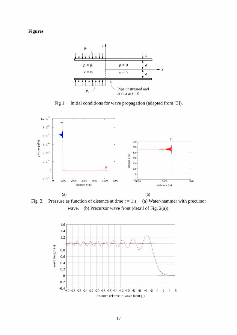
at time t = 0 is shown in Fig. 1. The pressure p and axial fluid velocity v have positive initial
values p0 and v0 in the left half of the tube (z < 0), respectively, related by
0 0 0p cv , (1)
where 0
Kc
. (2)

6
All other pressures, velocities and displacements are zero. These initial conditions correspond
to a step wave moving in the positive axial direction (z > 0) at speed c. The wave would
propagate in an unchanged form in a pipe with entirely rigid walls, but not so in a pipe with
elastic walls.
Skalak used the following data in his test problem: a = 0.3048 m, h = 4.857 mm, 0 = 999.8
kg/m3, K = 2.322 GPa, s = 7849 kg/m
3, E = 206.8 GPa, = 0.3, and herein p0 = 100 kPa.
Thus, c = 1524 m/s and v0 = 0.06563 m/s.
Skalak's model
Skalak considered axisymmetric thin-walled tubes. His mathematical model included in
addition to standard water-hammer theory the effects of radial inertia of liquid and pipe, and
longitudinal stress waves in the pipe wall. Bending stresses and rotatory inertia in the pipe
wall, that may be of importance near steep wave fronts and near pipe anchors, were also taken
into account. Axisymmetric shear deformation, fluid viscosity and lobar (non-circular) modes
of wall vibration were neglected. The influence of lobar modes on axial vibration is small at
low frequencies because there is no significant oval-axial interaction mechanism.
FSI four-equation model
In addition, Skalak presented a simplified model that is the low-frequency limit of the two-
dimensional fluid and shell representations. This so-called "FSI four-equation model" describes
the axial/radial vibration of liquid-filled pipes. Two equations for the liquid are coupled with two
equations for the pipe, through terms proportional to Poisson’s contraction ratio, and through
mutual boundary conditions. Skalak showed that the "FSI four-equation model" permits
solutions that are waves of arbitrary shape travelling without dispersion at the phase velocity of
either the liquid or the pipe, but he made no attempt to solve the four equations in general. The
model has been validated experimentally by many researchers [8], most notably by Vardy and
Fan [11], and it can be solved exactly [1213]. This model is well-known and not pursued herein.
Skalak's solution
Skalak applied Fourier and Laplace transforms to find dispersion relationships for the modes
of free vibration of the coupled fluid-pipe system. He applied inverse Fourier and Laplace
transforms to arrive at solutions in the form of single indefinite integrals of real-valued
functions. The integrals were too difficult to solve exactly, but Skalak was able to find
asymptotic solutions for large values of axial distance z and time t. An important result,

7
analysed herein, and recognised by others: "His doctoral dissertation [2] was on the water-
hammer effect, and it received enough attention that the engineering director of the Grand
Coulee Dam project used the theoretical results to predict pressure wave propagation effects
at distances of several miles from the dam" [1].
Skalak's asymptotic solutions revealed that wave fronts spread out proportionally to the cube
root of time, and that the pressure near a sharp wave front may exceed the classical
Joukowsky value as a result of radial pipe/fluid vibration. Skalak predicted and quantified
precursor waves in the fluid. These are pressure changes provoked by axial stress waves in the
pipe wall and thus preceding the main water-hammer waves. Precursor waves were actually
observed in metal and plastic pipes by Thorley [14] and by Williams [15].
The re-calculated solution to Skalak's test problem is shown to scale in Fig. 2(a). The water-
hammer wave has travelled a distance of c1 t = 980.9 m at time t = 1 s. The precursor, hardly
visible at the scale of Fig. 2(a), but magnified in Fig. 2(b), has travelled a distance of c2 t =
5279 m. The wave speeds c1 and c2 are
1
22 2 2 2 2 2 2
1,2
2 (1 ) 2 (1 ) 4 (1 )(2 )
2(2 )
AR R R AR R R R A Rc c
A R
, (3)
where c1 has the minus sign and c2 the plus sign, and where
A = 0
s
a
h and R =
2
0
c
c, (4)
with c0 defined below. Here A = 7.994 and R = 12.47. The water-hammer wave speed c1 is an
extension of the Korteweg formula ce, and the precursor wave speed c2 is approximately the
wave speed in thin plates c0, with
2
1
e
cc
K a
Eh
and 0 2(1 )s
Ec
. (5)
Here, ce = 981.9 m/s and c0 = 5381 m/s.
The pressure at z = 0 in Fig. 2(a) is substantially lower than p0 = 105 Pa, because the
impedance p/v (at z = 0) is not equal to p0/v0, but to 0 c1 = (c1/c)(p0/v0). The oscillations

8
trailing the wave fronts are not due to numerical error, but predicted by the theory. Figure 3
shows these oscillations in a non-dimensional diagram, which is assumed to be independent
of the early history. The horizontal axis gives the dimensionless distance relative to the wave
front,
* 3( ) n n nz z c t d t , (6)
where the index n is 1 for the water-hammer wave and 2 for the precursor wave. The
constants dn are defined by
5 3
2
22 2
( 4) (1 )
16 (2 ) 8 (2 1) 8 (1 )
n n n
n
n
c c cA R R
c c cd ca
cA R R A R
c
. (7)
Here, d1 = 2.926 m3/s and d2 = 11.48 m
3/s. The original dn given by Skalak contains a (h/a)
2-
term that has been left out here, not only because it is small, but also because it could not be
re-derived. The vertical axis in Fig. 3 gives the dimensionless wave height through the
integral
3
1
33
0 0
sin( )1 1 1( ) d Ai( )d
2 3
n
nnI , (8)
which has been drawn as a function of * 31 n nz with
3( )
nn
n
d t
z c t
. (9)
The upper bound in the first integral is +∞ for n > 0 and ∞ for n < 0. Three integrals can be
calculated analytically:
(0 ) 1I , (0 ) 0I and 1
( )3
I . (10)
The other integrals have been calculated numerically for 1000 values of n in the range 107
to 10+3
, with the upper bound in the first integral in Eq. (8) as large as possible [16]. Using
tables of Ai the Airy function of the first kind Skalak [17] computed numerically the
second integral in Eq. (8). The integral I, and hence the wave height, is constant when n is
constant, which is along the curves
9
3n
nn
d tz c t
(11)
in the distance-time plane. The wave front, where n = ±∞ and 31 n = 0, is clearly
identified as the only point travelling at both constant speed, cn, and constant dimensionless
height, 1/3.
The dimensional pressure for water-hammer (n =1) and precursor (n =2) waves travelling in
the positive z direction is (up to a constant, vertical shift):
3
0
sin( )( ) dn
n n n np Cp Cw
, (12)
with 20
2
2
2
1
nn
n
cCp
ca
c
, 0
1n
ns n
pCw
ch D
c
, 4 2 220 0
2 2 22 2
2 02 2
4 21
1 1
nn
ns
n
c cD
ac chc a
c c
,
where a (h/a)2-term has been neglected in Dn. Here, Cp1 Cw1 = 26105 Pa and Cp2 Cw2 =
146.5 Pa.
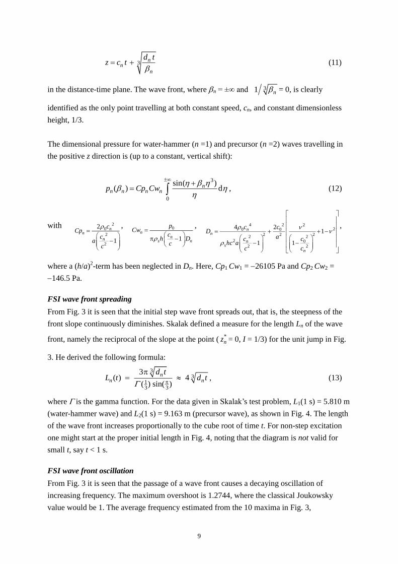
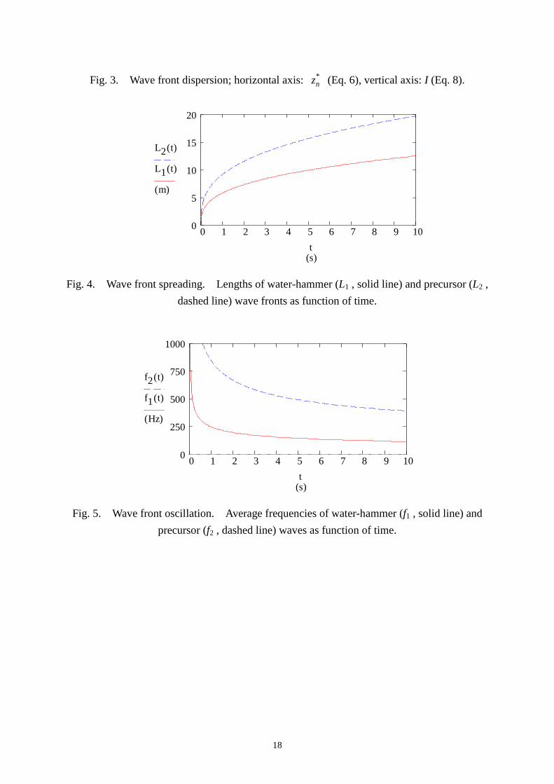
FSI wave front spreading
From Fig. 3 it is seen that the initial step wave front spreads out, that is, the steepness of the
front slope continuously diminishes. Skalak defined a measure for the length Ln of the wave
front, namely the reciprocal of the slope at the point ( *nz = 0, I = 1/3) for the unit jump in Fig.
3. He derived the following formula:
3
313 3
3( ) 4
( ) sin( )
nn n
d tL t d t , (13)
where is the gamma function. For the data given in Skalak’s test problem, L1(1 s) = 5.810 m
(water-hammer wave) and L2(1 s) = 9.163 m (precursor wave), as shown in Fig. 4. The length
of the wave front increases proportionally to the cube root of time t. For non-step excitation
one might start at the proper initial length in Fig. 4, noting that the diagram is not valid for
small t, say t < 1 s.
FSI wave front oscillation
From Fig. 3 it is seen that the passage of a wave front causes a decaying oscillation of
increasing frequency. The maximum overshoot is 1.2744, where the classical Joukowsky
value would be 1. The average frequency estimated from the 10 maxima in Fig. 3,

10
propagating at almost the speed cn, is
3
( ) 0.36 1.44 n nn
nn
c cf t
Ld t. (14)
This average frequency decreases in time as displayed in Fig. 5. The average frequency f1
decreases from about 250 Hz at t = 1 s to about 100 Hz at t = 10 s, which is much lower than
the ring frequency of a freely vibrating pipe hoop,
ring
0
1( )
2
s
Ef
aa
h
, (15)
where the coefficient determines the added fluid mass. In the literature values of of 1/4,
1/3 and 1/2 have been proposed [1821], depending on the assumed distribution of the radial
fluid velocity. Here, the values fring(1/4) = 1550 Hz, fring(1/3) = 1400 Hz and fring(1/2) = 1200
Hz are much higher than the values of f1 (t > 1 s) in Fig. 5. Interaction with longitudinal fluid
and pipe modes has been totally ignored in the derivation of fring. The cut-on frequency of the
lowest lobar mode (ovaling) of vibration is 16 Hz [16].
Dimensionless charts
Introducing the dimensionless quantities
* c
t ta
, * nn
LL
a, * n n
af f
c, * n
n
cc
c,
*
2 n
n
dd
c a, (16)
Eqs. (13) and (14) become
* * * *3( ) 4n nL t d t (17)
and
*
* *
* *3( ) 0.36 n
n
n
cf t
d t. (18)
The parameters *nc and *
nd depend on A, R and . The wave speed c in Eq. (16) depends
only on the properties of the contained fluid, and c is about 1500 m/s for water. It should be
noted that for water-hammer problems the real time t is related to t * by * *1
1
a c a L
t t tc c L c
,
where L is the length of the pipeline and L/c1 is the fundamental time scale in water hammer.
Water-filled steel pipe

11
Typical values of A, R and for a water-filled steel pipe are: A =1
8
a
h, R = 12.5 and = 0.3.
Figure 6 displays the dependence of * *1( )L t on the ratio a/h of pipe radius to wall thickness.
The length of the water-hammer wave front is at most of the order of ten pipe diameters, and
thicker pipe walls lead to shorter wave fronts. Correspondingly, thicker pipe walls give higher
frequencies of wave front oscillation, as shown in Fig. 7.
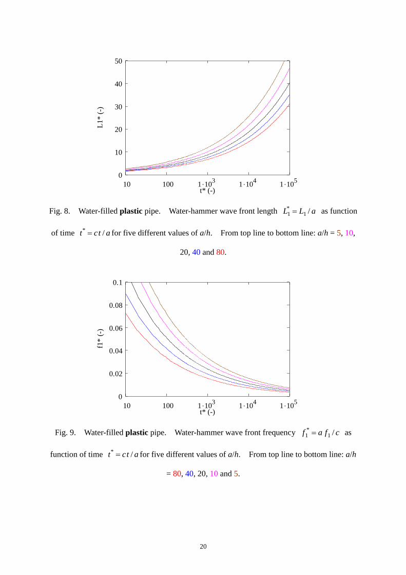
Water-filled plastic pipe
In plastic pipes viscoelastic behaviour of the wall material influences wave dynamics [9, 22],
but in the vicinity of steep wave fronts an instantaneous elastic response is expected instead of
a retarded viscous response. Additionally, the strong dependence of c1 on a/h in plastic pipes
makes it worthwhile pursuing the elastic approximation.
Typical values of A, R and for a water-filled plastic pipe are: A =a
h, R = 1 and = 0.4.
Because R = 1, the dimensionless wave speeds are * 21 (1 ) /(2 1) c A and *
2 1c , so
that the precursor wave speed c2 is independent of A and . Figures 8 and 9 display * *1( )L t
and * *1 ( )f t . Like the steel pipe, the wave front length is of the order of ten diameters, but
surprisingly the front length decreases for increasing ratio a/h. This means that for given
pipe radius, thicker pipe walls cause more dispersion. Further investigation of this fact
showed that for a very thin-walled steel pipe the same phenomenon occurs: for ratios a/h
larger than 112, *1L decreases for increasing a/h. Similarly, for very thick-walled plastic
pipes, with a/h smaller than 0.24, *1L decreases for decreasing a/h. This behaviour can be
explained from the strong a/h-dependence of the wave-speed ratio *1 1/ c c c , shown in Fig.
10, as a consequence of pipe hoop elasticity. The plastic pipe (Fig. 10(b)) has much smaller
values of 1 /c c than the corresponding steel pipe (Fig. 10(a)), and this has according to Eq.
(7) a strong effect on *nd . The much smaller values of
*1 1/c c c also explain (see Eq. (18))
that the frequencies in the plastic pipe (see Fig. 9) are much smaller than the corresponding
frequencies in the steel pipe (see Fig. 8).
Practical considerations

12
Skalak’s theory describes reflection-free wave propagation in long liquid-filled pipes. In
cross-country pipelines, the pressure waves in the liquid may travel long distances without
significant reflection, but the stress waves in the wall will meet pipe supports and/or anchors
at regular intervals. The stress waves will partly reflect from these supports, and most likely
non-axisymmetric bending will be generated. The influence of these reflections on Skalak’s
results is unknown.
Skalak’s instantaneous and flat excitation is difficult to realise in practice [23]. Only the
collapse of column separation regions [24] and the impact of gas shock waves [2528] may
be similar to such an extreme excitation. This means that the trailing oscillations associated
with radial vibration will be difficult to generate.
The smoothing of the wave front is found to be very small and will be difficult to distinguish
from other damping effects in laboratory tests and field measurements. For example, in an
analysis similar to Skalak’s, Bahrar et al. [29] have shown that fluid viscosity has a significant
long-term effect on the dispersion of the wave front.
Skalak’s asymptotic solution is valid for large time t and z (compared to radius a). In his
approximations, terms of the order of 1/t have been neglected, which formally means that
1t . Unfortunately, Skalak has not made the time t non-dimensional. Also, long wavelength
approximations have been made, where the wavelength 2 a and 1 12 / d c ,
although the local behaviour near wave fronts includes short wavelengths. The loss of
accuracy caused by the truncation of several integrals is another matter of concern.
Nevertheless, Skalak’s theory has been partly confirmed by others in the impact of elastic bars
[17, 23, 30] and in water hammer in liquid-filled pipes [29, 3132].
Conclusion
Skalak’s asymptotic solution describing the propagation and dispersion of water-hammer (n=1)
and precursor (n=2) waves has been investigated. The solution is shown in the “universal”
Fig. 3 and it is valid for large zn = cn t. Skalak defined the important length scale 3nd t ,
which stretches the wave front and trailing oscillation in Fig. 3. Skalak presented results for
one test problem, the solution of which is shown to scale in Fig. 2. New estimates of front
length and average frequency of oscillation are given for a range of situations in the
dimensionless diagrams Figs. 69. The main conclusion from these diagrams is that in

13
unrestrained water-filled steel and plastic pipes wave front spreading due to FSI is small, at
most of the order of ten pipe diameters. This may be considered as the worst-case steepness of
pressure wave fronts in liquid-filled pipes.
Acknowledgement
Parts of this paper have been presented at Euromech Colloquium 484 on Wave Mechanics and
Stability of Long Flexible Structures Subject to Moving Loads and Flows, Delft, The
Netherlands, September 2006, and at the 23rd IAHR Symposium on Hydraulic Machinery
and Systems, Yokohama, Japan, October 2006. The funding support of the Australian
Research Council is gratefully acknowledged.

14
References
[1] T.C. Skalak, A dedication in memoriam of Dr. Richard Skalak, Annual Review of Biomedical
Engineering 1 (1999) 1-18.
[2] R. Skalak, An extension of the theory of water hammer, PhD Thesis, Faculty of Pure Science,
Columbia University, New York, USA, 1954.
[3] R. Skalak, An extension of the theory of waterhammer, Water Power 7/8 (1955/1956) 458-462/
17-22.
[4] R. Skalak, An extension of the theory of water hammer, Transactions of the ASME 78 (1956)
105-116.
[5] E.B. Wylie, V.L. Streeter, Fluid Transients in Systems, Prentice Hall, Englewood Cliffs, USA,
1993.
[6] D.J. Leslie, A.S. Tijsseling, Travelling discontinuities in waterhammer theory: attenuation due
to friction, Proceedings of the 8th International Conference on Pressure Surges (Ed. A.
Anderson), The Hague, The Netherlands, 2000, pp. 323-335. Published by BHR Group,
Cranfield, UK, and Professional Engineering Publishing, Bury St Edmunds, UK.
[7] A.E. Vardy, J.M.B. Brown, Friction-dependent wavefront evolution, Proceedings of the 8th
International Conference on Pressure Surges (Ed. A. Anderson), The Hague, The Netherlands,
2000, pp. 337-349. Published by BHR Group, Cranfield, UK, and Professional Engineering
Publishing, Bury St Edmunds, UK.
[8] D.C. Wiggert, A.S. Tijsseling, Fluid transients and fluid-structure interaction in flexible liquid-
filled piping, ASME Applied Mechanics Reviews 54 (2001) 455-481.
[9] A. Bergant, A.S. Tijsseling, J.P. Vítkovský, D. Covas, A.R. Simpson, M.F. Lambert, Parameters
affecting water-hammer wave attenuation, shape and timing Part 1: Mathematical tools,
IAHR Journal of Hydraulic Research 46 (2008) in press.
[10] A. Bergant, A.S. Tijsseling, J.P. Vítkovský, D. Covas, A.R. Simpson, M.F. Lambert, Parameters
affecting water-hammer wave attenuation, shape and timing Part 2: Case studies, IAHR
Journal of Hydraulic Research 46 (2008) in press.
[11] A.E. Vardy, D. Fan, Flexural waves in a closed tube, Proceedings of the 6th International
Conference on Pressure Surges, BHRA (Ed. A.R.D. Thorley), Cambridge, UK, 1989, pp. 43-57.
[12] A.S. Tijsseling, Exact solution of linear hyperbolic four-equation systems in axial liquid-pipe
vibration, Journal of Fluids and Structures 18 (2003) 179-196.
[13] Q.S. Li, K. Yang, L. Zhang, Analytical solution for fluid-structure interaction in liquid-filled
pipes subjected to impact-induced water hammer, ASCE Journal of Engineering Mechanics
129 (2003) 1408-1417.
[14] A.R.D. Thorley, Pressure transients in hydraulic pipelines, ASME Journal of Basic
Engineering 91 (1969) 453-461.
[15] D.J. Williams, Waterhammer in non-rigid pipes: precursor waves and mechanical damping,
IMechE Journal of Mechanical Engineering Science 19 (1977) 237-242.

15
[16] A.S. Tijsseling, M.F. Lambert, A.R. Simpson, M.L. Stephens, J.P. Vítkovský, A. Bergant, Wave
front dispersion due to fluid-structure interaction in long liquid-filled pipelines, CASA Report
06-27, ISSN 0926-4507, Department of Mathematics and Computer Science, Eindhoven
University of Technology, The Netherlands, 2006.
[17] R. Skalak, Longitudinal impact of a semi-infinite circular elastic bar, ASME Journal of
Applied Mechanics 24 (1957) 59-64.
[18] F. Barez, W. Goldsmith, J.L. Sackman, Longitudinal waves in liquid-filled tubes II. Experiments,
International Journal of Mechanical Sciences 21 (1979) 223-236.
[19] A. Kellner, C. Schönfelder, The effect of fluid/structure interaction on pressure pulse loads on
pipes, 3R international 21 (1982) 443-449 [in German].
[20] J.S. Walker, J.W. Phillips, Pulse propagation in fluid-filled tubes, ASME Journal of Applied
Mechanics 44 (1977) 31-35.
[21] A.S. Tijsseling, Fluid-structure interaction in case of waterhammer with cavitation, PhD Thesis,
Faculty of Civil Engineering, Delft University of Technology, Communications on Hydraulic and
Geotechnical Engineering, Report No. 93-6, ISSN 0169-6548, Delft, The Netherlands, 1993.
Available from: http://www.darenet.nl/en/page/language.view/search.page.
[22] D. Covas, I. Stoianov, J.F. Mano, H. Ramos, N. Graham, C. Maksimovic, The dynamic effect
of pipe-wall viscoelasticity in hydraulic transients. Part II model development, calibration
and verification, IAHR Journal of Hydraulic Research 43 (2005) 56-70.
[23] E.C.H. Becker, H.D. Conway, Generation and use of mechanical step transients in dynamic
measurement, British Journal of Applied Physics 15 (1964) 1225-1231.
[24] A. Bergant, A.R. Simpson, A.S. Tijsseling, Water hammer with column separation: A historical
review, Journal of Fluids and Structures 22 (2006) 135-171.
[25] G.A.A. Asselman, Een onderzoek naar de schokvorm in de enkel-bel schokbuis, alsmede een
literatuurstudie van het gedrag van gasbellen in water, MSc Thesis, Report R-77-A,
Department of Applied Physics, Eindhoven University of Technology, Eindhoven, The
Netherlands, 1969 [in Dutch].
[26] C.J. Wisse, On frequency dependence of acoustic waves in porous cylinders, PhD Thesis,
Faculty of Geosciences, Delft University of Technology, Delft, The Netherlands, 1999.
Available from: http://www.darenet.nl/en/page/language.view/search.page.
[27] G.E. Chao, Dispersive surface acoustic waves in poroelastic media, PhD Thesis, Faculty of
Geosciences, Delft University of Technology, Delft, The Netherlands, 2005. Available from:
http://www.darenet.nl/en/page/language.view/search.page.
[28] Sh. Suzuki, Dynamic behaviour of thin cylindrical shells subjected to high-speed travelling
inner pressures, Ingenieur-Archiv 42 (1972) 69-79.
[29] B. Bahrar, E. Rieutord, R. Morel, G. Zeggwagh, Modeling of the waterhammer phenomenon
with respect to real pipe behavior, La Houille Blanche Revue Internationale de l'Eau 53
(1998) 18-25 [in French].
16
[30] F. Valeš, Š. Morávka, R. Brepta, J. Červ, Wave propagation in a thick cylindrical bar due to
longitudinal impact, JSME International Journal, Series A, 39 (1996) 60-70.
[31] T. Adachi, S. Ujihashi, H. Matsumoto, Impulsive responses of a circular cylindrical shell
subjected to waterhammer waves, ASME Journal of Pressure Vessel Technology 113 (1991) 517-
523.
[32] D. Sumarsono, Onde de pression dans un liquide confine par un tube souple, PhD Thesis,
Department of Mechanical Engineering, University of Orleans, Orleans, France, 1993 [in
French].
17
Figures
p0
p0
p = p0
v = v0
p = 0
v = 0
a
a
h
z
r
Pipe unstressed and
at rest at t = 0
Fig 1. Initial conditions for wave propagation (adapted from [3]).
0 1000 2000 3000 4000 5000 60002 10
4
0
2 104
4 104
6 104
8 104
1 105
1.2 105
distance z (m)
pre
ssure
p (
Pa)
w
p
4000 5000 6000100
0
100
200
300
400
500
600
distance z (m)
pre
ssure
p (
Pa)
p
(a) (b)
Fig. 2. Pressure as function of distance at time t = 1 s. (a) Water-hammer with precursor
wave. (b) Precursor wave front (detail of Fig. 2(a)).
30 28 26 24 22 20 18 16 14 12 10 8 6 4 2 0 2 4 60.4
0.2
0
0.2
0.4
0.6
0.8
1
1.2
1.4
1.6
distance relative to wave front (-)
wav
e hei
ght
(-)
18
Fig. 3. Wave front dispersion; horizontal axis: *nz (Eq. 6), vertical axis: I (Eq. 8).
0 1 2 3 4 5 6 7 8 9 100
5
10
15
20
(s)
L2 t( )
L1 t( )
m( )
t
Fig. 4. Wave front spreading. Lengths of water-hammer (L1 , solid line) and precursor (L2 ,
dashed line) wave fronts as function of time.
0 1 2 3 4 5 6 7 8 9 100
250
500
750
1000
(s)
f2 t( )
f1 t( )
Hz( )
t
Fig. 5. Wave front oscillation. Average frequencies of water-hammer (f1 , solid line) and
precursor (f2 , dashed line) waves as function of time.

19
10 100 1 103
1 104
1 105
0
10
20
30
40
50
t* (-)
L1
* (
-)
Fig. 6. Water-filled steel pipe. Water-hammer wave front length *1 1 /L L a as function
of time * /t ct a for five different values of a/h. From top line to bottom line: a/h = 80, 40,
20, 10 and 5.
10 100 1 103
1 104
1 105
0
0.2
0.4
0.6
t* (-)
f1*
(-)
Fig. 7. Water-filled steel pipe. Water-hammer wave front frequency *1 1 /f a f c as
function of time * /t ct a for five different values of a/h. From top line to bottom line: a/h
= 5, 10, 20, 40 and 80.
20
10 100 1 103
1 104
1 105
0
10
20
30
40
50
t* (-)
L1
* (
-)
Fig. 8. Water-filled plastic pipe. Water-hammer wave front length *1 1 /L L a as function
of time * /t ct a for five different values of a/h. From top line to bottom line: a/h = 5, 10,
20, 40 and 80.
10 100 1 103
1 104
1 105
0
0.02
0.04
0.06
0.08
0.1
t* (-)
f1*
(-)
Fig. 9. Water-filled plastic pipe. Water-hammer wave front frequency *1 1 /f a f c as
function of time * /t ct a for five different values of a/h. From top line to bottom line: a/h
= 80, 40, 20, 10 and 5.

21
0 20 40 60 80 1000
0.2
0.4
0.6
0.8
1
a/h (-)
c1* (
-)
0 20 40 60 80 1000
0.2
0.4
0.6
0.8
1
a/h (-)
c1
* (
-)
(a) (b)
Fig. 10. Water-hammer wave speed *1 1 /c c c as function of a/h, for (a) water-filled steel
pipe, and (b) water-filled plastic pipe.