
Waterways, Wetlands and Drainage Guide - Part B:...
14
14-1 Pipeline Structures Page 14.1 Introduction 14-3 14.2 Stormwater Gravity Pipelines 14-3 14.3 Pressure Pipelines 14-6 14.4 Manholes 14-7 14.5 Sumps 14-8 14 .6 Pipe Inlet Structures 14-9 14.7 Pipe Outfall Structures 14-10 14.8 References 14-13 Waterways. Wetlands and Drainage Guide - Ko Te Anga Whakaora mii Nga Arawai Repii • Part B: Design Christchurch City Council • February 2003
Transcript of Waterways, Wetlands and Drainage Guide - Part B:...
14-1
Pipeline Structures
Page
14. 1 Introduction 14-3
14.2 Stormwater Gravity Pipelines 14-3
14.3 Pressure Pipelines 14-6
14.4 Manholes 14-7
14.5 Sumps 14-8
14.6 Pipe Inlet Structures 14-9
14.7 Pipe Outfall Structures 14-10
14.8 References 14-13
Waterways. Wetlands and Drainage Guide - Ko Te Anga Whakaora mii Nga Arawai Repii • Part B: Design Christchurch City Council • February 2003
14-2 Chapter 14: Pipeline Structures
Port B: Design February 2003
Waterways, Wetlands and Drainage Guide-Ko Te Anga Whakaora rna Nga Arawai Repa Christchurch City Council
14.1 Introduction The Christchurch Drainage Board was founded in the 1870's to provide a comprehensive drainage network that allowed Christchurch to expand over the swampy plain. Initially, the artificial drainage network comprised predominantly lined and unlined open drains. Some impressive large diameter brick barrel stormwater sewers, which are still in use today, were installed within the central city's four avenues.
The Christchurch Drainage Board embarked on a vigorous waterway piping programme as infill development occurred. Post-war, the programme accelerated to the point where many kilometres of reinforced concrete stormwater pipe mains were laid each year to replace open waterways.
It is now recognised that waterway piping on a large scale is unsustainable because the pipes need to be replaced within approximately 100 years. This places a high cost on future generations. Waterway naturalisation is currently seen as the appropriate improvement option in most circumstances. Not only is waterway naturalisation more affordable in the long-term, but it also provides opportunities to realise a wide range of environmental and social values as well.
Pipeline structures include:
pipelines (including stormwater gravity pipelines and pressure pipelines)
manholes (for maintenance access and transitions)
sumps (for direct entry of smface water)
pipe inlet structures (where open waterways discharge into a pipeline)
pipe outfall structures (where a pipeline discharges into an open waterway).
These pipeline structures are discussed in the following sections. Subsoil drainage pipelines are not discussed in this chapter; refer to Chapter 5.3.1: Grollndwater Dmina,Re.
The traditional approach to designing waterway structures has been to ensure hydraulic capacity, structural integrity, and safety. While these criteria must always be applied, the design process must now also consider all values associated with waterways and wetlands.
Chapter 14: Pipeline Structures 14-3
14.2 Stormwater Gravity Pipelines Stormwater piping may be installed:
under road side channels where side channel capacity is insufficient
at road crossings
where open drains categorised in the Proposed City Plan (Christchurch City Council 1999) as utility waterways have deteriorated, become polluted, have declined base flows, and space is insufficient for naturalisation.
Where a stormwater pipeline replaces an open drain it may be necessary to connect a subsoil drainage pipe to the pipeline to ensure similar groundwater control functions to the former artificial watenvay.
Safe secondary flow paths must always be identified as an integral component of any stormwater pipeline design. All new designs must not only identify secondary flow paths, but ensure they are protected. Secondary flow paths on private property should also be legally protected.
Stormwater pipelines on private property must always be legally protected by way of a drainage easement in favour of the Christchurch City Council.
When stormwater pipelines are to be replaced, consider "day lighting" (restoring an open waterway), where space allows. Piping is inappropriate for waterways categorised in the Proposed City Plan (Christchurch City Council 1999) as environmental asset or hill waterways, and some utility waterways.
14.2.1 Pipeline Alignment and Minimum Size
Gravity pipelines should normally be laid in straight lines and at a constant gradient between access points such as manholes, sumps, and inspection chambers. Refer to Section 14.4: Manholes (Location and Spacing), for allowable lengths. With larger diameter pipelines, bends are permissible in certain situations.
Stormwater lines are normally located in the road between the central sanitary sewer and a line 1.5 m from the kerb. It is important to locate pipes where they will not compromise any future tree planting. It may be economic to lay pipes up to a 525 mm diameter under the side channel. Stormwater pipes within roads should have a minimum diameter of 225 mm.
The stormwater designer must always check that surface floodwater cannot enter sewer manhole vents. Sanitary sewers are normally laid in the centre of the road equidistant from adjacent properties, but
Waterways. Wetlands and Drainage Guide-Ko Te Anga Whakaoro ~ii Ngo Arawai Repii • Part B: Design February 2003 Christchurch City Council •
14-4 Chapter 14: Pipeline Structures
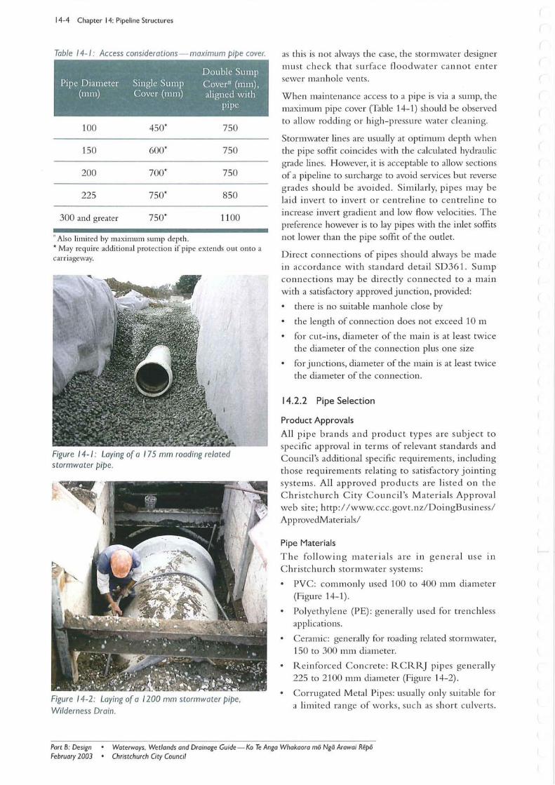
Table 14-1: Access considerations - maximum pipe cover.
Double Sump Pipe Diameter Single Sump Cover" (mm),
(mm) Cover (m111) aligned with pipe
100 450* 750
150 600* 750
200 700* 750
225 750* 850
300 and greater 750* 1100
" Also limited by maximum sump depth. * May require additional protection if pipe extends out onto a carr iageway.
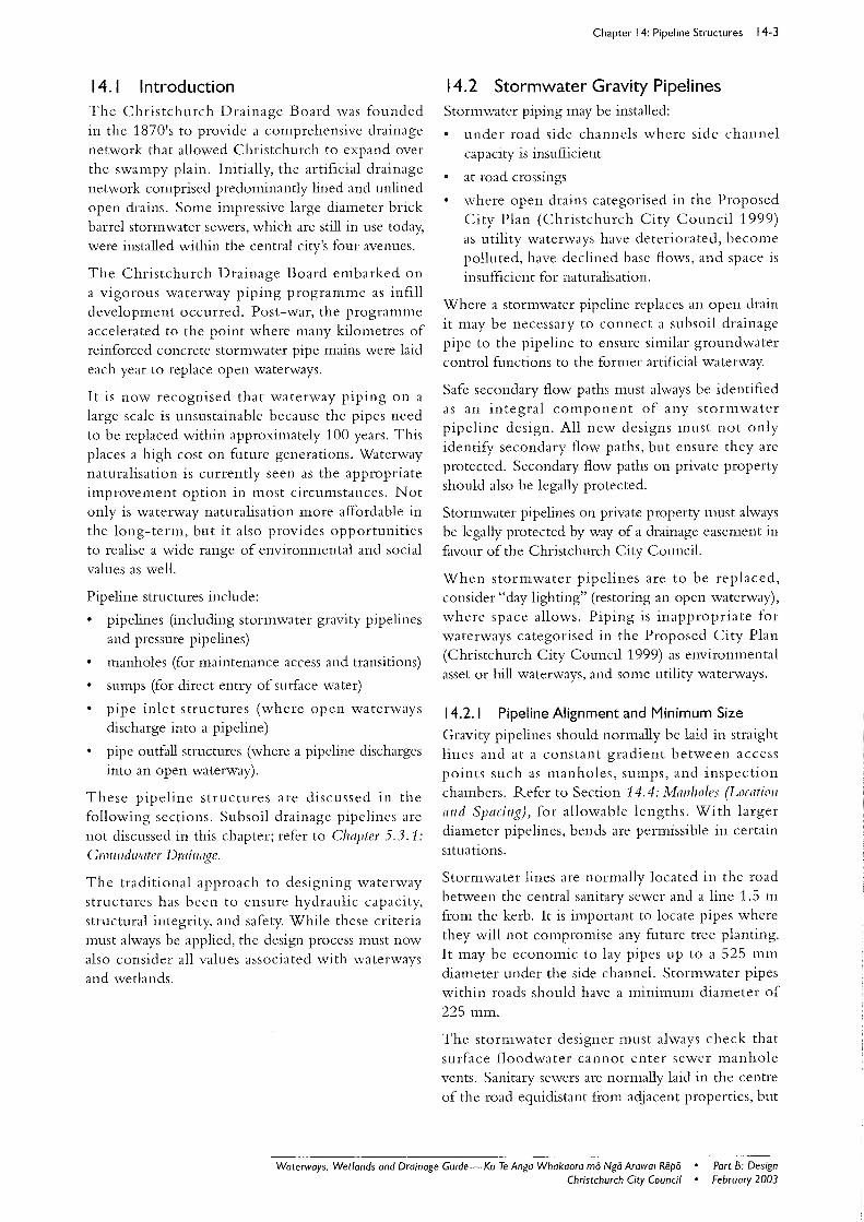
Figure 14- 1: Laying of a 175 mm roading related stormwater pipe.
Figure 14-2: Laying of a 1200 mm stormwater pipe. Wilderness Drain .
as this is not always the case, the stormwater designer mu st check that surfa ce floodwater cannot ente r sewer manhole vents .
When maintenance access to a pipe is via a sump, the maximum pipe cover (Table 14-1) should be observed to allow rodding or high-pressure water cleaning.
Stormwater lines are usually at optimum depth when the pipe soffit coincides with the calculated hydraulic grade lines. However, it is acceptable to allow sections of a pipeline to surcharge to avoid services but reverse grades should be avoided. Similarly, pipes may be laid invert to invert or centreline to centreline to increase invert gradient and low flow velocities. The preference however is to lay pipes with the inlet soffits not lower than the pipe soffit of the outlet.
Direct connections of pipes should always be made in accordance with standard detail SD361. Sump connections may be directly co nnected to a mall1 with a satisfactory approved junction, provided:
there is no suitable manhole close by
the length of connection does not exceed 10m
for cut-ins, diameter of the main is at least twice the diameter of the connection plus one size
for junctions, diameter of the main is at least twice the diameter of the connection.
14.2.2 Pipe Selection
Product Approvals
All pipe brands and product types are subject to specific approval in terms of relevant standards and Council's additional specific requirements, including those requirements relating to sa tisfactory jointing sys tems. All approved products are listed on the Christchurch City Council's Materials Approval web site; http: //www.ccc.govt.nz/ DoingBusiness/ ApprovedMaterials/
Pipe Materials
The following materi als are in general us e in Christchurch stormwater systems:
PVC: commonly used 100 to 400 mm diameter (Figure 14-1) .
Polyethylene (PE): generally used for trenchless applications.
Ceramic: generally for roading related stormwater, 150 to 300 mm diameter.
Reinforced Concrete: RCRR] pipes generally 225 to 2100 mm diameter (Figure 14-2) .
Corrugated Metal Pipes: usually only suitable for a limited range of works, such as short culverts.
Part B: DeSign February 2003
• Waterways . Wetlands and Drainage Guide-Ko Te Anga Whakaora mii Ngii Arawai Repii • Christchurch City Council
Care should be taken when specifying because pipe friction is significantly greater than that of other pip es, jointing systems are often not watertight, and the joints are often open enough to permit entry of fine soil particles.
Flexible pipes more than 4 m deep require special design and specific approval of Council.
Structural Design
Manufacturer's loading and structural design criteria must be followed .
Pipe Sizes
When specifying pipe sizes, care should be taken when rounding up to nearest pipe size to utilise ranges that are currently available. For example, if calculations indicate a pipe diameter of 240 mm, then 250 mm should be specified, allowing for either 250 mm or 300 mm. Also, to avoid confusion, always specify pipes by nominal inside diameter (ID) .
14.2.3 Pipe Laying
Bedding and Haunching
Pipes shall be haunched and bedded in accordance with one of the standard detail options shown on standard detail SD344.
For concrete pipes use standard detail SD344/Sheet 1:
Type C: concrete haunching on metal foundation (now rarely used)
Type M: metal haunching, with or without metal foundation (normal use)
Type H: concrete haunching for full trench width (for hillside pipes close to rock).
For PVC, PE, and ceramic pipes use standard detail SD344, Sheet 2. For hill piping special lime stabilised mixes shall be used (refer CSS Part 3; Christchurch City Council 2002) .
Earth loads on deep pipelines can increase quite significantly when the pipelines are laid in overvvide trenches. This might be countered in part with special bedding and side support, or the use of co ncrete haunching with rigid pipe typ es.
Where weak soils such as peat occur at , or below bedding level, the replacement of highly compressible soils with the usual imported granular fill material can cause settlement of both the pipeline and trench surface. This is because of the substantial difference in weight of the imported material. Such conditions may warrant the use of piling, in which case smaller pipes may require some form of reinforced concrete strengthening to take bending between piles. Joint
Chapter 14: Pipeline Structures 14-5
flexibility should be retained even with piling. Test bores may be required.
As an alternative to piling, a raft foundation will often b e adequate. However, this must allow ade quate load spreading such that the long-term soil bea ring capacity is not exceeded . In areas where there are no special scour, aggressive groundwater, or bedding problems, bedding shall be as follows:
concrete pipes: Type M (metal) from SD344
PVC, PE, or ceramic pipes: Type P (standard haunching).
Should th e trench bottom be unsa tisfactory as a foundation (and /o r where there is danger of the surrounding soils or bac kfill migrating into the haunching or foundation metals) an appropriate geotextile shall be placed prior to placing the foundation and haunching metal (Figure 14-1) .
Aggressive groundwater, such as water with high CO2, may require concrete bedding (Type C), or the provision of a protective coating, or polyethylene loose sleeve wrap. A map showing areas of high CO2
is included in the City Council's Code of Prac tice (Wastewater Drainage).
Hillside Pipes On Bedrock
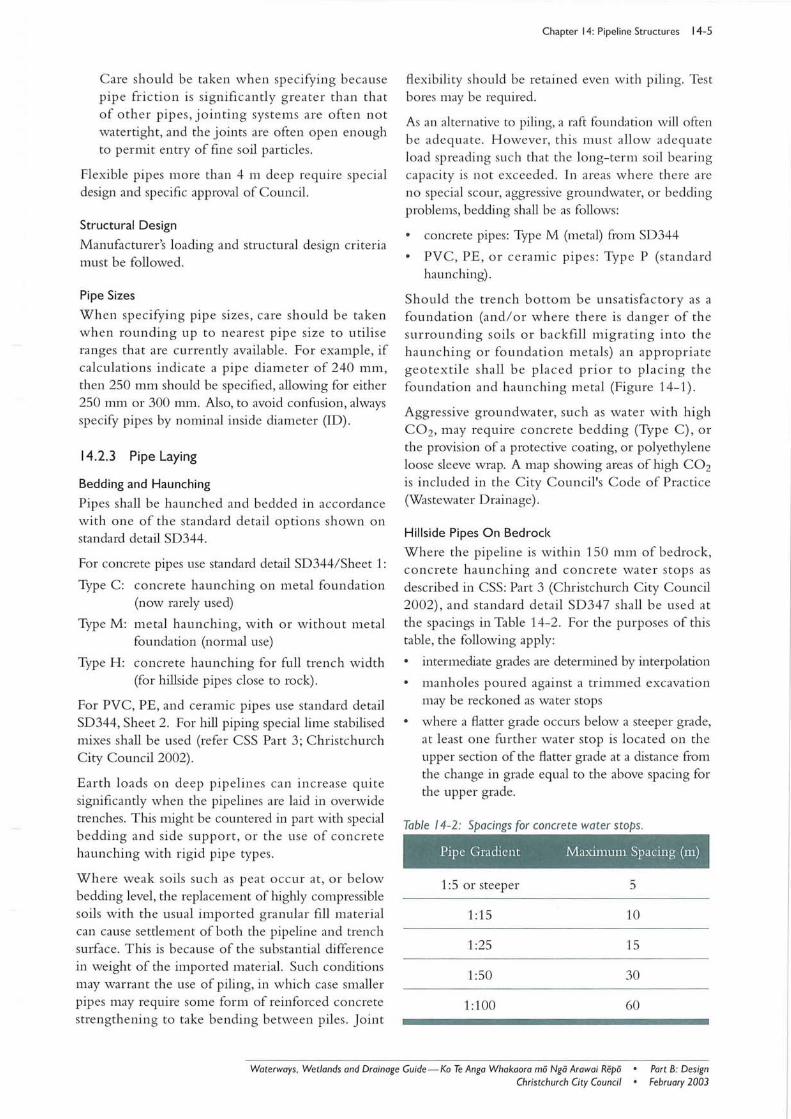
Where the pipeline is within 150 mm of bedrock, concrete haunching and concrete water stops as described in CSS: Part 3 (Christchurch City Council 2002), and standard detail SD347 shall be used at the spacings in Table 14-2. For the purposes of this table, the following apply:
intermediate grades are determined by interpolation
manholes poured against a trimmed excavation may be reckoned as water stops
where a flatter grade occurs below a steeper grade, at least one further water stop is located on the upper section of the flatter grade at a distance from the change in grade equal to the above spacing for the upper grade.
Table 14-2: Spacings for concrete water stops.
Pipe Gradient Maximum Spacing (m)
1: 5 or steeper 5
1 :15 10
1:25 15
1:50 30
1:100 60
Waterways . Wetlands and Drainage Guide - Ko Te Anga Whakaora rno Ngo Arawai Repo • Part B: Design February 2003 Christchurch City Council •
14-6 Chapter 14: Pipeline Structures
Hillside Trenchline Scour
Special requirements for hillside pipes are aimed at ensuring the stability and durability of pipelines by providing the most appropriate bedding and backfill to control movement of groundwater along the trench and erosion of loess. In general this will be achieved by the addition of hydrated lime to the backfill materials to bind the finer constituents and, through lime migration, the soil immediately adjacent to the trench. Where lime stabilised backfill is used and the pipeline is not close to rock, then concrete waters tops are not required. The specific requirements are described in more detail in CSS: Part 3 (Christchurch City Council 2002).
A hillside is defined (in this section) as any location where either the pipe gradient or smface slope directly uphill or downhill is steeper than 1 in 20, or any other location where large variations in groundwater levels could cause enough water movement within a trench for bedding scour to occur.
Joints at Sumps or Manholes
Where pipes are connected to sumps or manholes, at least two yield joints and one short pipe should be provided. At manholes in roads, 2 shorts and 3 yield joints are required (in accordance with standard detail SD341, Sheets 1,2, and 3).
Pipe Protection
Concrete pipe protection may be used where the pipe cover does not comply with the manufacturer's design criteria. Options for pipe protection, both surround and capping are shown in standard detail SD342. Note that for PVC and PE, only Type E is suitable. Sufficient cover should be allowed for any road surfacing.
14.2.4 Longitudinal Gradients
Minimum Gradients
In flat areas, gradients should be kept as steep as possible to control silt deposition. The designer should aim to achieve a velocity of at least 0.6 m/s at a flow of half of the 2 year storm flow. Reverse grades should be avoided wherever possible, even when the 0.6 m/s velocity provision is achievable. For larger pipes (> 600 mm ID), and especially for those pipes conveying hillside discharge into a tidally influenced outfall, consideration should be given to a more detailed sedimentation analysis, as well as future maintenance cleaning provisions.
Also refer to Chapter 7.4: Design Considerations for Hill
Hlaterways.
Maximum Gradient
When pipe gradients are steeper than 1 in 3 for lengths greater than 3 metres, consider the problem of erosion of concrete and ceramic pipes by high velocity waterborne grit. When flows are continuous or frequent, wear resistant pipes such as cast iron, ABS or mPVC PN12, or other specially approved materials can be used. Concrete channelling can be protected with hard surfacing (e.g. epoxy sand mortar), or a resilient rubbery coating. Sacrificial layers can be used both in special concrete pipes or ill sitll structures.
Small diameter pipes carrying 'clean' stormwater may not need any special lining. Care must be taken to provide adequate pipe anchorage on steep gradients.
14.3 Pressure Pipelines Any rising main from a stormwater pumping station is a pressure pipeline. Construction materials are usually PVC or Polyethylene. The selection of pipe class and diameter shall be matched with pump and flow characteristics. Velocities should be high enough to transport solids but should not exceed 1.5 m/s and should not be lower than 0.6 m/s.
The pipeline shall be designed for static and friction heads, and some consideration should be given to possible water hammer or surge pressures. Given the relatively low operating pressures likely to be associated with stormwater pressure mains within Christchurch it is unlikely water hammer pressures will be significant.
Pressure Pipeline Gradients
Ideally, pressure pipelines should slope continually upwards from the pumping station to terminal. If summits are unavoidable, they must be provided with vents or combination air release valves of a type not prone to blockage. Gradients are less important for temporary pressure pipelines, but consider inclusion of vertical sections to provide pump starting head and pipeline charging.
Bedding
Pressure pipelines shall be bedded as per standard detail SD344.
Thrust Blocks
Pressure pipelines shall be provided with thrust blocks at bends as per standard detail SD346. In the case of upward thrust, full restraint must be obtained from the dead weight of the thrust block. Special design may be warranted when there are high heads, large pipes, or unusual ground conditions.
Part B: Design February 2003
• Waterways. Wetlands and Drainage Guide-Ko Te Anga Whakaora rna Nga Arawai Repa • Christchurch City Council
14.4 Manholes
Location and Spacing
Manholes are located at regular intervals along a pipeline to provide access and changes in direction.
Manholes should preferably be positioned on roadways, However, where this is not possible vehicle access should be provided to facilitate any maintenance activities.
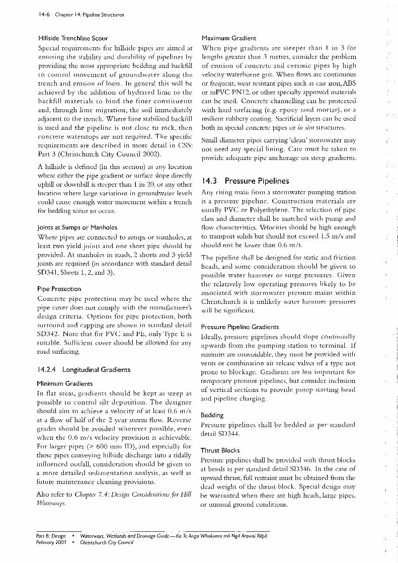
Table 14-3 below indicates the range of maximum spacings. Factors that indicate the choice of a lower maXll11um spacll1g are:
deposition of silt (especially adjacent to hills)
tidal conditions
sand entry
cleaning methods (manual, water jet, or bucket machine) .
Vented Manholes
Vented manholes are not normally required in the stormwater system as there is generally adequate venting at the entry points. However, where high or low air pressures could occur, the need for venting should be assessed. Such locations include sea outfalls subject to wave surge and steep hill lines where significant suction and blowing can occur.
Structural Aspects
Manholes shall either be standard, narrow, or special , as shown on standard details SD302, 303, and 304. Special manholes are usually required for larger pipes, especially where changes of direction are involved. They should incorporate the same opening as a standard manhole and sho uld be designed to withstand heavy traffic loading HN-HO-72 (see Appendix 4). For small structures, a wheel load of 70 kN should be allowed for, with impact allowances as follows:
cover less than 300 mm: 30 %
cover less than 600 mm: 20 %
cover less than 900 mm: 10%
thereafter: 0%
Larger manholes should be checked for flotation . The factor of safety against floating should be at least 1.2, excluding skin friction in the completed condition, with empty manhole and saturated ground. Increased forces resulting from larger depth and spans may be resisted by thicker walls, or reinforcing. Yield joints between manholes and pipes shall be provided in accordance with standard detail SD341.
Chapter 14: Pipeline Structures 14-7
Unreinforced vertical concrete panels in manholes or other underground structures, subject to so il and traffic loading, should either be specifically designed or, in the case of a square panel, the length of the side should not exceed seven times panel thickness.
The 28 day concrete crush ing strength for all manholes shall be 25 MPa.
Ladders should be placed clear of the flow from sidelines.
The maximum size of pipe for a standard 900 mm square manhole should be 825 mm diameter ID.
Fall Through Manholes
When there is a change of pipe size at a manhole, the soffit of the inlet pipes should generally not be lower than the soffit of the outlet pipe, except where pipes will not run full at maximum design flow. In this situation it will be permissible to lay the pipes so that surface levels corresponding to uniform maximum flow in each pipe coincide.
To fully utilise the ungorged capacity of a piped system operating at uniform flow, the fall across a manhole should reflect the energy loss across it.
However, in approved circumstances it may be preferable to have a smaller inlet pipe with soffit lower than the outlet pipe, in order to avoid other services, to increase cover, or to increase the grade to reduce silting.
Refer to the Chapfer 22.9.5: Cu/'Jerf aud Pipe BC/ld Losses,Jor typical bend loss coefficients.
Table 14-3: Maximum spacings for manholes.
Diameter Maximum Spacing (111)
150-710 100*
710-920 100-120
920-1120 100-150
1120-1320 100- 180
1320-1420 120-220
1420-1850 120-250
1850 and above 150-250
*May be increased to 120 m e tres if the manholes are fixed ill position by virtue of being existing, or required by other
connections.
Waterways . Wetlands and Drainage Guide-Ko Te Anga Whakaora mii Ngii Arawai Repii • Part B: DeSign Christchurch City Council • February 2003
14-8 Chapter 14: Pipeline Structu res
14.5 Sumps The purposes of roadside sumps are to :
convey sto rmwater fro m the ground/ roa d slll{ace into the piped system
separate rubbish from the flow
trap silt, gravel, etc
give access to the stormwater pipe.
Stormwater Entry
For all typical roading projects, sumps and gratin gs should be chosen to fit the side channel. R efer to standard details SD321-SD328. H eavy-duty gratings may be necessary fo r heavy wheel loads. All sump grating types used in C hristchurch require special approval after w hich they will be listed on C ouncil's materials approval web site at http://www.ccc.govt. l1Z/D oingBusiness/ ApprovedMaterials/
The use of side entry sumps is generally discouraged, due to th e ri sk o f signifi cant am o unts of litte r entering the drainage system throu gh the side-entry slot. For this reason side- entry sumps are prohibited in or near commercial and industrial areas.
Side entry sum.ps may be considered in loca ti o ns w here sto rmwater outflows from blocked inle ts o r outlets could lead to inundation of properties, serious restri ction of traffi c o n collec tor o r arterial roads, or where longer conventional sumps (including hill sumps) are not practical. The use of side entry sumps
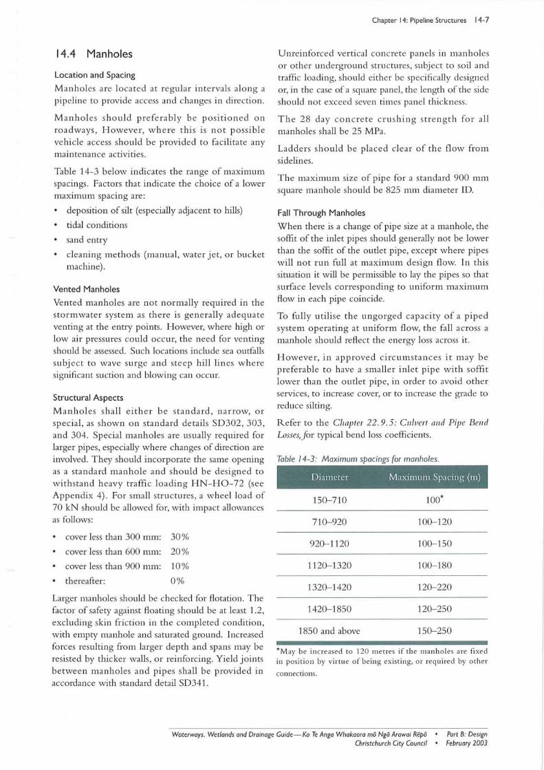
Figure 14-3: The design of hillside sumps requires special consideration to ensure the capture of adequate channel flow during stormflow conditions.
in these situations would depend on desired capacity, proximity to commercial or tree/ bush areas that may produce significa nt debris, and the susceptibility of dow nstrea m piping to blockage fro m de bris that could pass throu gh the larger side entrance.
If side entry sumps are used , miti ga tio n me as ures including methods to reduce sedime nt and litter transported downstream must be considered. T his is required to meet conditions relating to the discharge of clean stormwater in the Proposed R egional Policy Statement (Canterbury R egional Council 1998) .
Side entry sumps are permi tted and recommended on the downstream e nd of all " bubble up " sys te ms. However, sump ca pa citi es n o tw ithstandin g, th e designer should carefully investiga te requirements for valley positions where secondary flow paths are no t available, or in know n flood prone areas.
For retrofitting sumps within hillside channels where peak runoff does no t exceed 10 lis, it is permitted to use standard detail SD324, Sheet 2. Appropriate hill side ca tchments include sh o rt le n gths of hill right-of-ways.
When designing hill sumps, care mu st be taken to ensure adequate ca pture of ch annel flo w w h ere stormwater flow velocities may be high (Figure 14-3) .
See Chapter 22. 10: SIIIIIPS- Co llection of Water fro III Side Channels, for information on sump hydraulics.
Silt and Gravel Trapping
The well provided in sumps, below the outle t pipe invert level , collec ts stones and heavy debris. In the case of a multiple grating sump, this can sometimes be achieved by placing a bulkhead in th e middle , which will also support the walls and remove the need fo r deeper excavation.
D eep, narrow sumps should be avoided as they make access fo r cleaning pipelines difficult . Generally, the maximum depth for suction cleaning is two m etres.
Submerged outlets shall be used fo r sumps w hich collec t stormwater fl ow from large hard-standing areas, such as carparks, where there is potential for the build-up of floatable pollutants.
Master traps (standard detail SD 374, Sheet 1) may be required where priva te drains (piped or open, w here pipelines are 225 mm o r large r in diame ter) meet public piped drains. T he function of m aster traps is to control silt deposition in the pipeline as well as the movement of floatables and any po tentially dangerous gases. Typ e 2 sump s (E 1 / AS1 ; Building Indu stry Authority 2000) are generally accep table for hardstanding areas up to 800 m2
.
Part B: Design February 2003
• Waterways , Wetlands and Drainage Guide - Ko Te Anga Whakaora mii Ngii Arawai Ri!pii • Christchurch City Council
Sump Spacing
Sumps above underchannel piping shall be either:
(i) double sumps (with standard well) spaced no greater than 90 m apart; or
(ii) single sumps (with standard well) spaced no greater than 45 m apart, where the soffit of the underchannel pipe at the sump is no greater than 750 mm below the fender.
No well is necessary where a sump is 'bubbling up' storm water to the channel. The downstream 'bubble up' sump is to be the Side Entry IExit Type (standard detail SD 321).
Sumps on kerb and channel should be located to avoid access crossings. Preferred locations are opposite property side boundaries and one metre back from tangent points on the straight.
Vehicles and Safety
Where larger, non-standard sumps are to be used, then unreinforced walls should be checked for their capacity to withstand heavy traffic loads. Grates must also be able to carry the impact weight of a heavy vehicle.
The installation of sump grates must also consider safety issues. For example, grates on streets and pathways can cause bicycle accidents or trip people. Normally, the hazard to cyclists is minimal where a clearly defined side channel is provided. This is particularly important at intersections or locations where a cyclist may be crowded by a vehicle into the side channel.
The hydraulic efficiency of bars parallel to flow versus bars at right angles varies little for low flow velocities up to 1 mls (as is nonnally found on the flat), but can make a significant difference on the hills. Obviously, bars at right angles present less of a hazard to cyclists. Consider both factors in design.
Sumps as Features
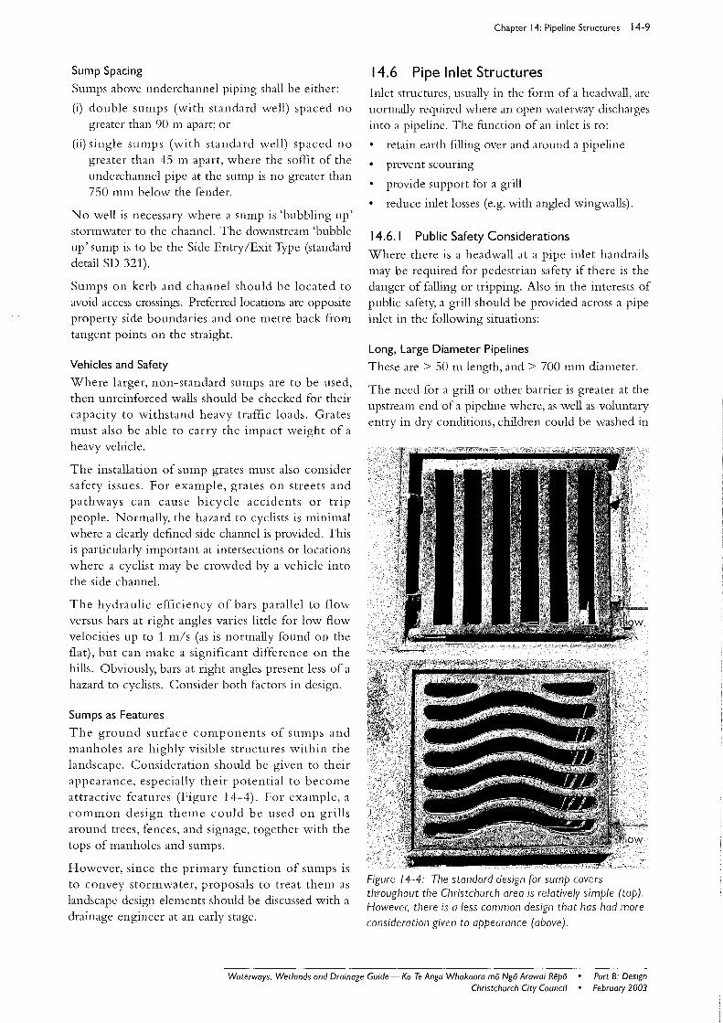
The ground surface components of sumps and manholes are highly visible structures within the landscape. Consideration should be given to their appearance, especially their potential to become attractive features (Figure 14-4). For example, a common design theme could be used on grills around trees, fences, and signage, together with the tops of manholes and sumps.
However, since the primary function of sumps is to convey stormwater, proposals to treat them as landscape design elements should be discussed with a drainage engineer at an early stage.
Chapter 14: Pipeline Structures 14-9
14.6 Pipe Inlet Structures Inlet structures, usually in the form of a headwall, are normally required where an open waterway discharges into a pipeline. The function of an inlet is to:
retain earth filling over and around a pipeline
prevent scouring
provide support for a grill
reduce inlet losses (e.g. with angled wingwalls).
14.6.1 Public Safety Considerations
Where there is a headwall at a pipe inlet handrails may be required for pedestrian safety if there is the danger of falling or tripping. Also in the interests of public safety, a grill should be provided across a pipe inlet in the following situations:
Long. Large Diameter Pipelines
These are> 50 m length, and> 700 mm diameter.
The need for a grill or other barrier is greater at the upstream end of a pipeline where, as well as voluntary entry in dry conditions, children could be washed in
Figure 14-4: The standard design for sump covers throughout the Christchurch area is relatively simple (top). However, there is a less common design that has had more consideration given to appearance (above).
Waterways. Wetlands and Drainage Guide - Ko Te Anga Whakaora mii Ngo Arawai Repa • Part B: DeSign February 2003 Christchurch City Council •
14-10 Chapter 14: Pipeline Structures
by flood flows. In a long pipeline, a child could be trapped under the water long enough to drown.
Short, Large Diameter Pipelines
A grill should be considered if there is deep ponded water within the pipeline or a hidden step down on the invert, otherwise the danger level could normally be considered as low.
Small Diameter Pipelines
Protection is not usually required for these. However, in the case of pipelines steeper than, say 1 in 2, where a small child could fall in and slide down, protection should be considered at the upper end if the diameter exceeds 300 mm.
Refer to Chapter: 13.4: Grills in TIVaterways, for information on grill design.
14.6.2 Debris Separation
Pipe Blockage
Short, straight pipelines often perform satisfactorily without protection. However, long pipelines, especially those less than 500 mm in diameter and incorporating changes of direction, need protection near the inlet from debris that can cause blockages. Remember that a suitably designed grill is much easier to clear than a blocked pipeline.
Inlet Blockage
In creating inlets regard must be given to their potential to act as debris traps, whether grilled or not. Consideration should be given to the amount and type of debris that can arrive at a point. For example, whether debris has already been separated by a debris trap a short distance upstream, or whether large volumes of twigs and branches could be washed into the waterway during storms.
Consider also the economic and other consequences of blockage of the pipe or grill, resulting from ponding and secondary overflow paths.
Refer to Chapter: 13.4: Grills ill TIVaterways, for information on grill design.
14.6.3 Other Considerations
Appearance
The final appearance of any inlet structure and its setting within the existing landscape is considered very important. Utilitarian fair face finish vertical concrete walls should be used only as a last resort. Designers are encouraged to be innovative within the context of the landscape setting.
With smaller diameter pipelines below 750 mm diameter, it may be possible to avoid concrete headwalls, depending on water velocities and scour potential. Dry wall rockwork with metal fill backing around a bevelled inlet pipe can be a practical, visually pleasing and cost-effective alternative. Landscape planting can add to such inlets.
For larger diameter pipe inlets, or where material is limited by hydraulic or soil constraints, design must provide for good visual appearance or incorporate careful landscape planting to soften hard lines, whilst not restricting hydraulic capacity. Rock or timber facings over concrete walls or a distinct rock band embedded in concrete are good design solutions.
Future Piping
Where piping is liable to be extended in the future, a headwall can be designed to be incorporated in a future manhole, or temporary headwalls can be constructed of treated timber or dry stone. Where the future piping may extend in a straight line, it may be useful to complete the pipeline with a socket.
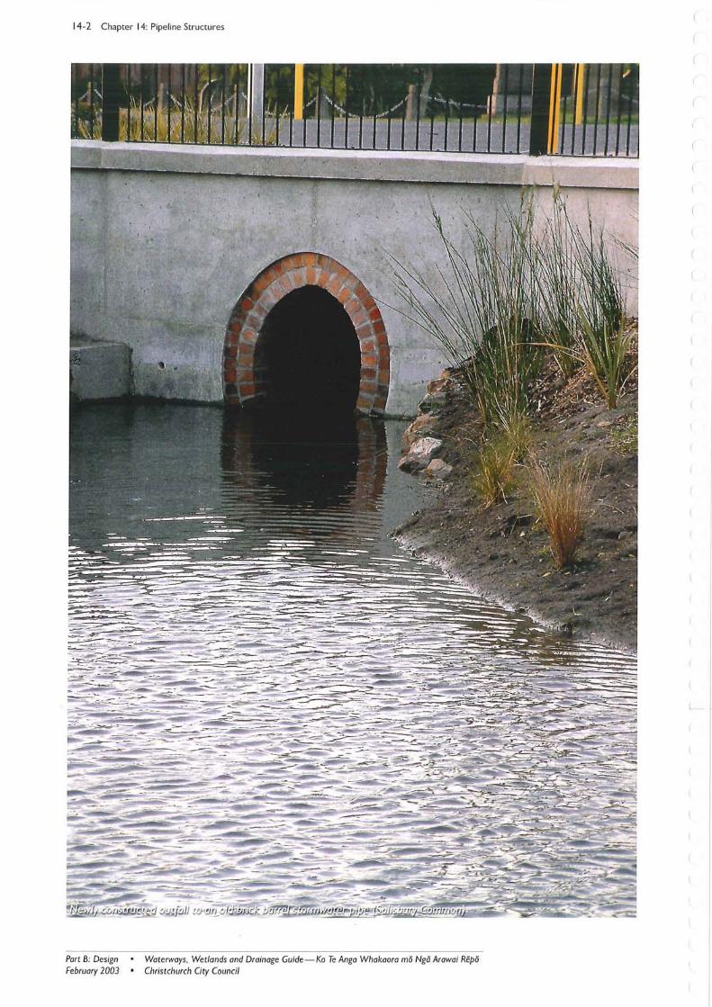
14.7 Pipe Outfall Structures Pipe outfall structures are generally necessary where a pipeline discharges into an open waterway. Design of outlet structures, shall have regard to:
bank and pipe stability
streambed erosion
opportunities to incorporate these as a landscape feature and integral to the design of the waterway and surrounding environment.
Concrete and PVC stormwater pipe outfalls that project beyond the bank are generally undesirable due to the following reasons:
they have a significantly adverse visual effect on open waterways (Figure 14-5A)
they ensure that any litter entering the stormwater system is deposited into a natural waterway
protruding outfalls, often protected by a reinforced concrete beam, cause local scour of the bank.
The designer should consider alternative materials where size, soil conditions, and outlet velocities permit (generally for outlet sizes below 750 mm diarneter).
Litter Interception
Site specific designs that meet landscape criteria and provide an opportunity for litter to be trapped before it enters the natural waterway are required. Potential options include the following:
Part B: Design February 2003
• Waterways, Wetlands and Drainage Guide-Ko Te Anga Whakaora mii Nga Arawai Repii • Christchurch City Council
A litter trap at, or upstream of, the pipe outfall .
Locating the pipe outfall several metres back from the water's edge and providing either a reed bed or rockwork chute to intercept litter. R egular removal of litter will be required.
14.7.1 Pipe Termination Details
The treatment of stormwater pipe terminations at waterways will depend on the pipe invert elevation above the dry weather water level.
Elevated Pipe Outfall
Where a stormwater pipe approaches a waterway at an elevated level, it can be dealt with in one of these two ways:
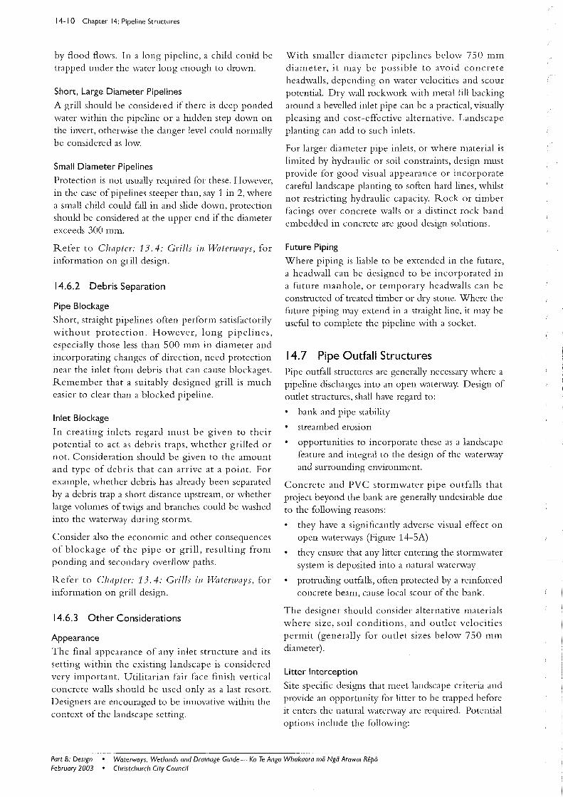
Termina te the pipe ou tlet a t the high level in an unobtrusive manner (similar to the low pipe ou tfaIl method), and cascade the flow down to the receiving water level via a rockwork chute (Figure 14-5B). This will help provide a landscape feature that will create a more natural
Figure 14-5A: Original outfall at Farnley Reserve. Heathcote River/ 6pawaho. 1992.
Figure 14-5B: The outfall was terminated at a high level. and a rockwork chute created to reduce the stormwater energy potential and erosion.
Figure 14-5C: With established vegetation the outfall has become a natural landscape feature. with the pipe outfall hidden from view.
Chapter 14: Pipeline Structures 14- 1 1
look . Exposure of concrete required to anchor any rockwork should be kept to a minimum, and the area should be planted to further naturalise the outfall (Figure 14-5C) .
Incorporate a drop structure (e.g. a manhole or co rner sump) away from the bank and then terminate using one of the methods desc ribed below for a low pipe outfall.
Low Pipe Outfall
Where the pipe outfall terminates at the water's edge, it is generally preferable to select a pipe invert level slightly below the dry weather water level in the receiving waterway- ideally with pipe invert submergence to 15 % to 25 % of pipe diameter.
Enhancing the appearance of the outfall ca n be achieved by various means, including:
Using a pipe colour th at will blend into the surrounding landscape.
Cutting the pipe end at an oblique angle, say 45 °.
Placing bank planting close to the outlet.
Waterways. Wetlands and Drainage Guide-Ka Te Ango Whakaora mi5 Nga Arawai Repi5 • Port B: Design February 2003 Christchurch City Council •
14-1 2 Chapter 14: Pipeline Structures
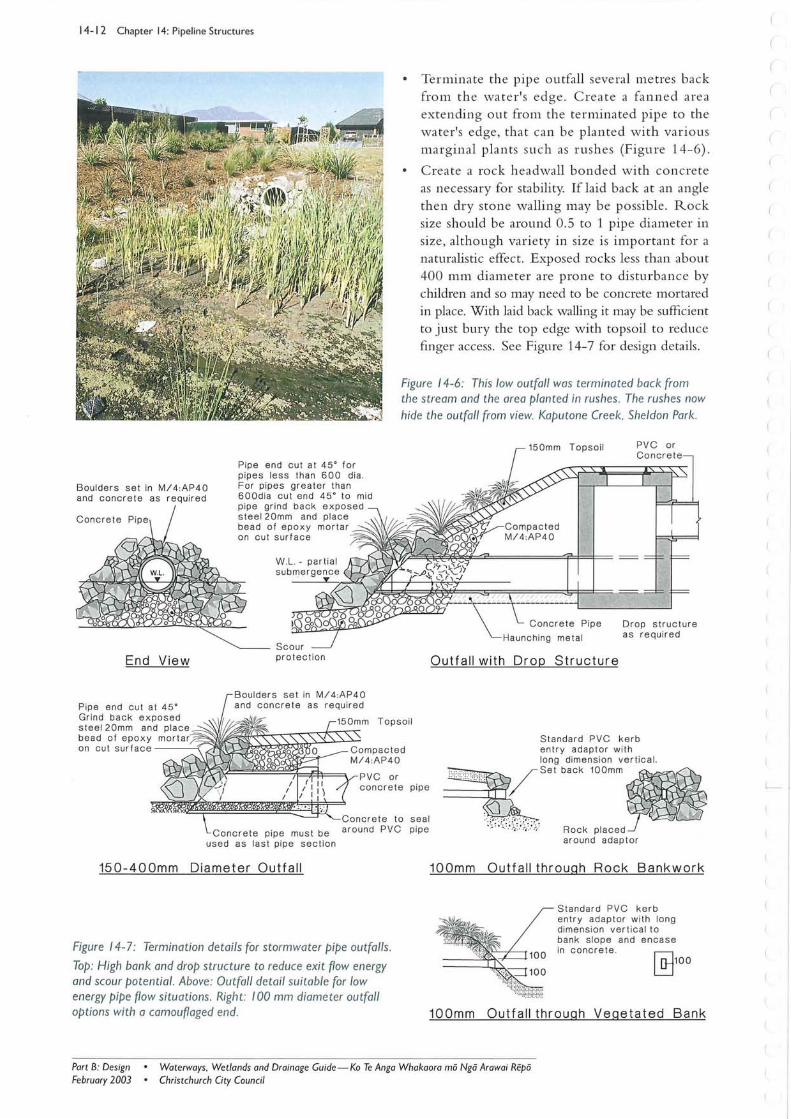
Boulders set in M/4 :AP40 and concrete as required
1
End View
Pipe end cut at 45· Grind back exposed steel20mm and place
Pipe end cut at 45· for pipes less than 600 dia . For pipes greater than 600dia cut end 45· to mid p ipe grind back exposed steel20mm and place bead of epoxy mortar on cut surface
protection
be ado f e po x y mor t ar r=_'f'VJr-;J~~~~~~:-,-~~::-; on cut surface ----{ \...
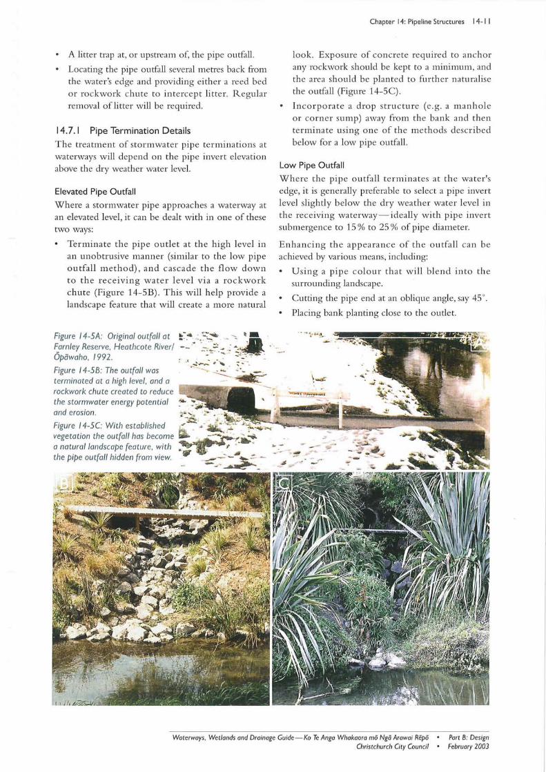
Terminate the pipe outfall several metres back from the water 's edge. Create a fa nn ed area extending out from the terminated pipe to the water's edge, that can be planted with various marginal plants such as rushe s (Figure 14-6).
Create a rock headwall bonded with concrete as necessa ry for stability. Iflaid back at an angle then dry stone walling may be possible. Rock size should be around 0.5 to 1 pipe diameter in size, although variety in size is important for a naturalistic effect. Exposed rocks less than about 400 mm diameter are prone to disturbance by children and so may need to be concrete mortared in place. With laid back walling it may be sufficient to just bury the top edge with topsoil to reduce finger access. See Figure 14-7 for design details.
Figure 14-6: This low outfall was terminated back from the stream and the area planted in rushes . The rushes now hide the outfall from view. Kaputone Creek, Sheldon Park.
Topsoil
Outfall with Drop Structure
Drop structure as required
Standa rd PVC kerb entry adaptor with
~~~~~~~~~~~~~==~~PVC or concrete pipe
~~~1b~;;,e",~g~~_
Concrete pipe must be used as last pipe section
150-400mm Diameter Outfall
Figure 14-7: Termination details for storm water pipe outfalls.
Top: High bank and drop structure to reduce exit flow energy and scour potential. Above: Outfall detail suitable for low energy pipe flow situations. Right: 100 mm diameter outfall options with a camouflaged end.
seal pipe . . '. -.' Rock Placed~
around adaptor
100mm Outfall through Rock Bankwork
100mm
Standard PVC kerb ent r y adaptor with long dimension ver tica l to bank slope and encase in concrete .
~100
Outfall through Vegetated Bank
Part B: Design February 2003
Waterways, Wetlands and Drainage Guide -Ko Te Anga Whakaora mo Ngo Arawai Repo Christchurch City Council
14.7.2 Pipe Stability Projecting concrete beams, as used in the past, are now considered unacceptable. In many cases these have been constructed without adequate bank protection, which has led to displacement of the entire beam and failure of upstream pipes.
Stabilising the riverbank and riverbed IS an important design consideration. In weak or scour prone soils, or where the pipeline discharges directly into a deep waterway channel, the end section of pipeline must be set onto an adequately stabilised base. This must extend beyond any potential zone of creep or settlement.
Full concrete surround will only be necessary away from the bank to protect pipes from surcharge loading in a low cover situation.
14.7.3 Outfall Erosion Protection Streambed erosion can result from excessive velocity from a stormwater outfall, or from the induced turbulence in the receiving stream flow where the outfall pipe protrudes past the line of the bank. Erosion can be mitigated by the following:
following the guidelines given for low pipe outfalls or elevated pipes (Section 14.7.1: Pipe TerJllillatioll Details)
stabilising the streambed; this could incorporate a properly designed plunge pool.
Outlet velocity should be determined by detailed hydraulic analysis, or by the generally conservative approximation for low gradient pipes that velocity head will be no more than the height from pipe soffit level to the dry weather water level. Conversion of velocity head (Hv) to a velocity follows the relationship of Equation 14-1:
V=~2gH\ Eqn (14-1)
Refer to Chapter 22.7: Bed Shear Stress alld the Stable Bed, for further information on stable substrate sizes.
14.8 References Building Industry Authority (BrA) 2000. Approl'ed DO(l//IIentE1: SllIface T¥ater. Standards Association, Wellington.
Canterbury Regional Council 1998. Proposed Regional Policy Statement. Report No 98/4. Canterbury Regional Council, Christchurch.
Christchurch City Council 1999. City of Christchllrch City Plall. The Proposed District Plall for
Chapter 14: Pipeline Structures 14-1 3
the City (if Christchllrch. Christchurch City Council, Christchurch.
Christchurch City Council 2002. Constl'llctioll Standard Spec~fication (CSS), Part 3: Utility Pipes. Christchurch City Council, Christchurch. Available from: http:www.ccc.govt.nz/Doing Business/ css/
Waterways. Wetlands and Drainage Guide-Ko Te Anga Whakaora ma Ngo Arawai Repa • Christchurch City Council •
Part B: Design February 2003