WATERSHIELIJrM - Softener Parts
6
WATERSHIELIJrM REVERSE OSMOSIS SYSTEM INSTALLA TION MANUAL p 1 ~ -~ ~ ~ I IMPORTANT I ~ ~ I THIS REVERSE OSMOSIS SYSTEM WAS SOLD IN KIT FORM. IT HAS ~ INOT BEEN PRESSURE TESTED IN ANY WAY. UPON INSTALLATION IT I IMUST BE PRESSURE TESTED FOR LEAKS. THE MANUFACTURER CAN I I NOT BE HELD RESPONSIBLE FOR ANY LEAK DAMAGE, INCIDENTAL OR I I CONSEQUENTIAL. IT IS THE SOLE RESPONSIBILITY OF THE INSTALLER ~ ~ l ~ TO INSURE THIS PRODUCT AND THE INSTALLATION THEREOF. ~ ~ ~ ~ ~ iYlYl7.17I/I/I/.I7IYIYIY.I7I/I/I/I/.I7lh17l/1/I/I/IY.I7I/I/.I7I7I/.IYI/I7I/I7I/I/I7I7I/I/I/I'7I/I/I'7I/I/I/1/1/..r/"'WI7.17I/I'7I/I'/.I7I/I7I/I'/I7I7I7I7I/1/.I/.I7I/.I7A1YI/I/I7I'/I7I~
Transcript of WATERSHIELIJrM - Softener Parts

WATERSHIELIJrMREVERSE OSMOSIS SYSTEM
INSTALLA TION MANUAL
p 1~ -~~ ~
I IMPORTANT I~ ~ITHIS REVERSE OSMOSIS SYSTEM WAS SOLD IN KIT FORM. IT HAS ~INOT BEEN PRESSURE TESTED IN ANY WAY. UPON INSTALLATION IT IIMUST BE PRESSURE TESTED FOR LEAKS. THE MANUFACTURER CAN IINOT BE HELD RESPONSIBLE FOR ANY LEAK DAMAGE, INCIDENTAL OR IICONSEQUENTIAL. IT IS THE SOLE RESPONSIBILITY OF THE INSTALLER ~~ l~ TO INSURE THIS PRODUCT AND THE INSTALLATION THEREOF. ~~ ~~ ~iYlYl7.17I/I/I/.I7IYIYIY.I7I/I/I/I/.I7lh17l/1/I/I/IY.I7I/I/.I7I7I/.IYI/I7I/I7I/I/I7I7I/I/I/I'7I/I/I'7I/I/I/1/1/..r/"'WI7.17I/I'7I/I'/.I7I/I7I/I'/I7I7I7I7I/1/.I/.I7I/.I7A1YI/I/I7I'/I7I~

"BIG pump"mAXImum now
S-STRGE HIGHnow
Pressure: 110 PSI
Operating pH: 4-11
Temperature:
Chlorine Tolerance: OPPM(Carbon Prefilter Required)INTU(Proper Sediment Prefilter Required)
Turbidity:
ALL PLUMBING SHOULD BE DONE IN ACCORDANCE WITHSTATE AND LOCAL PLUMBING CODES.
DO NOT USE WITH WATER THAT IS MICROBIOLOGICALLYUNSAFE OR OF UNKNOWN QUALITY WITHOUT ADEQUATEDISINFECTION BEFORE OR AFTER THE SYSTEM.

A. Reverse Osmosis System Components
1. Reverse_ Osmosis (RO) System2. Drinking Water Storage Tank3. Ball Valve for Storage Tank4. Saddle Valve Kit5. Faucet6. Drain Clamp
B. Items Not Included That May Be Necessary forInstallation
1. Wood or Steel Metal Screws for MountingReverse Osmosis Bracket to Wall.
2. Extra Tubing (114"), if supplied tubinginsufficient.
C. Tools Recommended For Installation
1. 3/8" Electric Drill2. Porcelain Hole Cutter Kit3. 118" & 112" Metal Drill Bits for Pilot Hole4. Center Punch & Hammer5. Assorted Wood and Metal Drill Bits for Pilot
Hole6. Phillips Head and Flat Head Screwdrivers7. 112",9/16", and 5/8" Open End Wrenches8. 10" Crescent Wrench9. Basin Wrench or 10" Pipe Wrench10. Teflon Tape11. Plastic Tubing Cutter
D. Site Selection for Reverse Osmosis
The Watershield Reverse Osmosis System can be installedunder the sink or wall mounted elsewhere due to spacelimitations. Access to a cold water line and drain arenecessary.
All tubing and reverse osmosis components should beinstalled in areas that have temperature above 38°F.
The drinking water storage tank may be placed under thesink or anywhere that is convenient within 10 feet of thefaucet. The tank can weigh up to 40 pounds when fulland should therefore be placed on a firm, level surface.
The self piercing valve should tap into the cold water line.The feed water should come from a potable cold watersupply line only. DO NOT USE the hot water supply line.
Waster water must go to the drain. Do not connect the ROsystem drain line to the dishwasher drain or near thegarbage disposal.
E. Installation Procedure
All plumbing should be done in accordance with state andlocal plumbing codes.
1. FAUCET INSTALLATION
[1] FAUCET INSTALLATION
-4-SPOUT
1~:~:"R GASKET-=-...- FACE PLATE (ESCUTCHEON)
--1-RUBBER COUNTERTOP PROTECTOR1%?l Wf411- MOUNTING SURFACE
-- "1-- LARGE WASHER
- "-SMALl WASHERtel --'-HEX NUT
mURE 2 - MOUNTING HARDWARE
(a) The easiest installation is to use an existing sprayattachment hole. If the spray hole is not available, the~ thesink top must be drilled.
(b) Drilling a hole for faucet installation.
Drilling a stainless steel sink-Center punch the hole to provide a starting point for thedrill. I-Start with a smaller drill as a pilot, and then drill a 112"diameter hole to accept the bolt.-Clean away any chips and debur any sharp edges.
Drilling a porcelain sink-It is best to use a speciall114" diameter cutter designed forporcelain. A carbide tipped masonry bit is a second choice.-Place a piece of tape over the area to be drilled to helpprevent chipping.-Drill a pilot hole for the porcelain cutter. !I
-When drilling the 1114" hole, drill slowly and carefully asthe porcelain chips easily. I
Drilling a counter top-Treat ceramic tiles as porcelain until the tile is penetrated,then use a carbide tipped metal cutter. Formica countertopsmay be drilled with a good 1114" wood bit, drilling a 3/32"pilot hole will help keep the bit going straight.(c) Assemble and attach the faucet
-Place the rubber gasket followed by the face plate andrubber countertop protector on the faucet stud.-From the top of the counter place the stud through themounting hole.-From the bottom of the counter top in the following orderassemble the large steel washer, small washer and hex nut.-To the end of the stud, insert the poly tubing as follows:
-insert the tubing through the compression nut andplastic ferrule-place the insert into the tube opening-screw the compression nut into the threaded stud
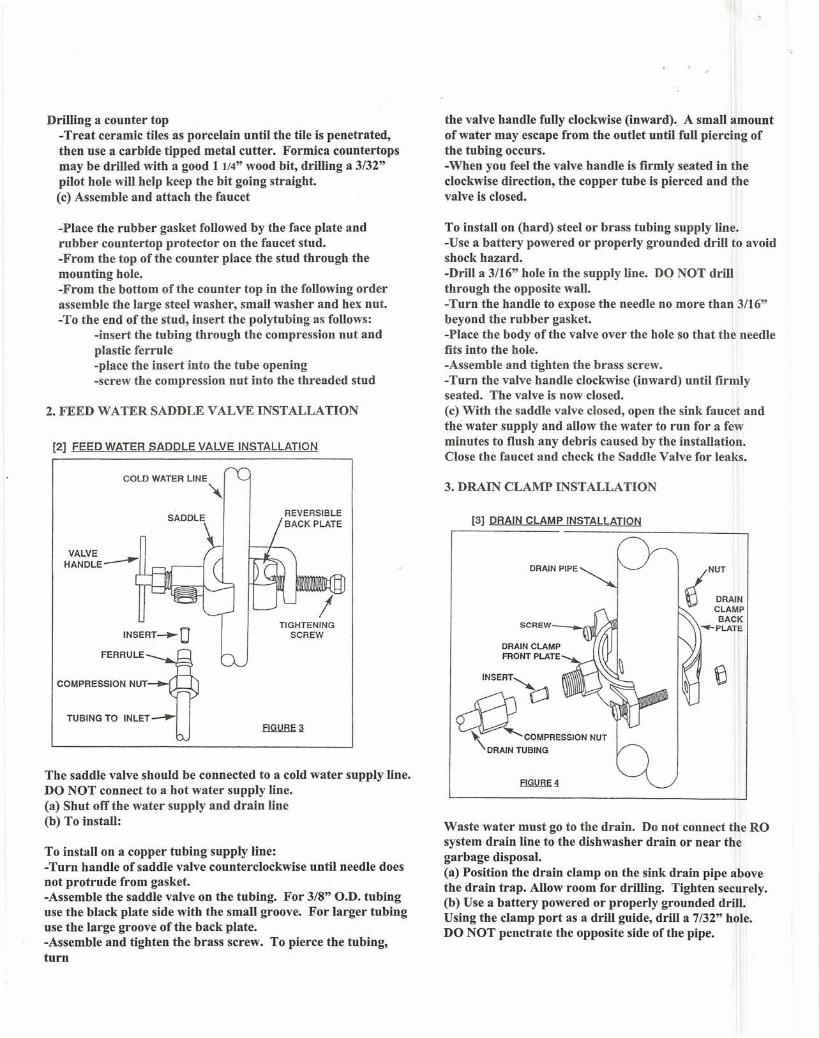
2. FEED WATER SADDLE VALVE INSTALLATION
[2] FEED WATER SADDLE VALVE INSTALLATION
SADDLE
COLD WATER LINE
~
ITIGHTENING
SCREW
The saddle valve should be connected to a cold water supply line.DO NOT connect to a hot water supply line.(a) Shut offthe water supply and drain line(b) To install:
To install on a copper tubing supply line:-Turn handle of saddle valve counterclockwise until needle doesnot protrude from gasket.-Assemble the saddle valve on the tubing. For 3/8" O.D. tubinguse the black plate side with the small groove. For larger tubinguse the large groove of the back plate.-Assemble and tighten the brass screw. To pierce the tubing,turn
the valve handle fully clockwise (inward) -. A small amountof water may escape from the outlet until full piercing ofthe tubing occurs.-When you feel the valve handle is firmly seated in theclockwise direction, the copper tube is pierced and thevalve is closed.
To install on (hard) steel or brass tubing supply line.-Use a battery powered or properly grounded drill to avoidshock hazard.-Drill a 3/16" hole in the supply line. DO NOT drillthrough the opposite wall.-Turn the handle to expose the needle no more than 3/16"beyond the rubber gasket.-Place the body ofthe valve over the hole so that the needlefits into the hole.-Assemble and tighten the brass screw.-Turn the valve handle clockwise (inward) until firmlyseated. The valve is now closed.(c) With the saddle valve closed, open the sink faucet andthe water supply and allow the water to run for a fewminutes to flush any debris caused by the installation.Close the faucet and check the Saddle Valve for leaks.
3. DRAIN CLAMP INSTALLATION
[3] DRAIN CLAMP INSTALLATION
DRAIN PIPE ./NUT
\) DRAINCLAMPBACK
--PLATESCREW_--..~
DRAIN CLAMPFRONT PLATE
INSERT~
~C~R""O,"",DRAIN TUBING
Waste water must go to the drain. Do not connect the ROsystem drain line to the dishwasher drain or near thegarbage disposal.(a) Position the drain clamp on the sink drain pipe abovethe drain trap. Allow room for drilling. Tighten securely.(b) Use a battery powered or properly-grounded drill.Using the clamp port as a drill guide, drill a 7/32" hole.DO NOT penetrate the opposite side of the pipe.

' ..
(c) Install the compression nut and brass insert through thetubing, and tighten the compression nut to the drain clamp.
4. RO SYSTEM INSTALLATION(a) The RO should be mounted firmly and securely. Themounting bracket will accept #10 or #12 screws. Allow atleast10" clearance beneath the housings to accommodate filtercartridge changes.(b) Install the mounting screws and tighten slightly.(c) Hang the mounting bracket on the mounting screws andtighten. Do not over tighten.(d) Run the orange tubing (feed line), trim to appropriate length,and insert it into the saddle valve.(e) Run the black tubing (drain line), trim to appropriate length,and insert it into the drain clamp.(1)Run the blue tubing (purified water), trim to appropriatelength, and insert it into faucet stud.(g) The yellow tubing should be connected to the drinking waterstorage tank.
5. DRINKING WATER STORAGE TANK(a) Check the tank pressure, the pressure should be 7-12 PSI. Usea hand pump or bicycle pump to adjust pressure.(b) Wrap teflon tape around nipple oftank and screw in holdingtank ball valve.(c) Insert the yellow tubing into the ball valve. Make sure thetubing is pressed firmly and securely into the fitting hole. Thefitting will grab the tubing and hold it in place.
6. STARTUP(a) Open the saddle valve fully counterclockwise.
(b) The holding tank ball valve should be closed.(c) Open the faucet and let the RO system rinse out for 20minutes. II(d) Shut off faucet. Open the holding tank ball valve.(e) Do not open the faucet for 8 hours. Let the tanklflll andthen open the faucet to empty the tank. Repeat this Iprocedure 3 times. Do not drink water from these threerinses.
7. CHANGING FILTERS AND MEMBRANE
WARNING: The RO Membrane is shipped with apreservative in it (Sodium Metasulfite). This will beremoved with the rinsing of the system. Discard the waterfrom these rinses. II
The RO system contains filters which must be changed atregular intervals. The recommended interval for tYilicalconditions is every 6 months. Your Watershield RO comeswith high quality sediment and carbon block filtercartridges. It is recommended these cartridges be replacedwith similar quality cartridges. Poor quality cartridges canresult in inadequate pre-filtration, damage the reverreosmosis membrane, and compromise drinking watelil quality.Only filter cartridges recommended by your waterconditioning professional should be used. The reverseosmosis membrane should typically be replaced evei~ 2-3years depending on usage and water quality. Consult yourwater treatment professional for servicing and filter changes.

Limited Warranty
The Watershield Reverse Osmosis System, when installed and operatedwithin the recommended parameters, is warranted to be free of defects inmaterials and workmanship for a period of 1 year. The manufacturer willrepair or replace at its discretion during the warranty period any defectivecomponent. This warranty does not cover the disposable sediment orcarbon cartridges whose service life depends upon the quality of feedwater. The reverse osmosis membrane will not be warranted if therequired pre-filter conditions to the membrane are not followed.
Conditions of Warrantt
The above warranty shall not apply to any part of the Watershield ReverseOsmosis System that is damaged because of occurrence including but notlimited to neglect, misuse, alteration, accident, misapplication, physicaldamage, or damage caused by fire, act of God, freezing or hot water. If theunit is altered by anyone other than the manufacturer, the warranty isvoid.
To obtain warranty service, contact the local dealer who supplied thesystem. It is the obligation of the owner to pay for shipping or travelcharges to return the defective part.
This is the only warranty made by the manufacturer with respect to itWater shield Reverse Osmosis Systems. No other warranty, expressed orimplied, is given including merchantability or fitness for a particularpurpose, incidental or consequential damages, or their losses.
This exclusion applies to the extent exclusion is permitted by law.
No person or representative is authorized to assume for the manufacturerany liability on its behalf, or in its name, except to refer the purchaser tothis warranty.
Watershield is a registered trademark of Water Treatment Warehouse, Inc.© 2004, Water Treatment Warehouse, Inc. Printed in U.S.A.