
Water Wrangling: Restoring and Rejuvenating Hydraulic Excellence
108
Water Wrangling: Restoring and Rejuvenating Hydraulic Excellence in Siem Reap May 12, 2005 ENGR340 Team 15 Monsoon Platoon Ben Giudice, Kevin Gritters, Dan Vander Heide © 2005, Calvin College and Ben Giudice, Kevin Gritters, and Dan Vander Heide
Transcript of Water Wrangling: Restoring and Rejuvenating Hydraulic Excellence

Water Wrangling: Restoring and Rejuvenating Hydraulic Excellence in Siem Reap
May 12, 2005
ENGR340
Team 15 Monsoon Platoon
Ben Giudice, Kevin Gritters, Dan Vander Heide
© 2005, Calvin College and Ben Giudice, Kevin Gritters, and Dan Vander Heide

I. EXECUTIVE SUMMARY................................................................................................................................3 II. INTRODUCTION/OVERVIEW ......................................................................................................................4
A. GENERAL .........................................................................................................................................................4 B. HYDRAULIC HISTORY ......................................................................................................................................5
1. History of the Siem Reap River...................................................................................................................5 2. History of Barays........................................................................................................................................6 3. History of Mountain Dams .........................................................................................................................7
III. CHALLENGE ...............................................................................................................................................8 A. GENERAL .........................................................................................................................................................8 B. DESIGN NORMS..............................................................................................................................................10
1. Cultural Appropriateness .........................................................................................................................10 2. Transparency............................................................................................................................................10 3. Integrity ....................................................................................................................................................10 4. Stewardship ..............................................................................................................................................11 5. Justice.......................................................................................................................................................11 6. Caring.......................................................................................................................................................11 7. Trust..........................................................................................................................................................11
IV. SOLUTION..................................................................................................................................................12 A. CHANNEL AND RIVER ....................................................................................................................................12
1. Purpose.....................................................................................................................................................12 2. Site ............................................................................................................................................................12 3. Social and Environmental Considerations ...............................................................................................14 4. Hydrology.................................................................................................................................................14 5. Design.......................................................................................................................................................15 6. Safety ........................................................................................................................................................25 7. Cost Analysis ............................................................................................................................................25
B. RESTORATION OF THE EAST BARAY...............................................................................................................27 1. Purpose.....................................................................................................................................................27 2. Site ............................................................................................................................................................27 3. Social and Environmental Considerations ...............................................................................................29 4. Hydrology.................................................................................................................................................29 5. Design.......................................................................................................................................................30 6. Safety ........................................................................................................................................................49 7. Cost Analysis ............................................................................................................................................50
C. MOUNTAIN DAM............................................................................................................................................52 1. Purpose.....................................................................................................................................................52 2. Site ............................................................................................................................................................52 3. Social and Environmental Considerations ...............................................................................................53 4. Hydrology.................................................................................................................................................55 5. Design.......................................................................................................................................................58 6. Safety ........................................................................................................................................................67 7. Cost Analysis ............................................................................................................................................68
V. DISCUSSION ...................................................................................................................................................69 A. COORDINATION BETWEEN MOUNTAIN DAM AND EAST BARAY ......................................................................69
1. Necessity of baray and dam......................................................................................................................69 2. Controls ....................................................................................................................................................70
B. CONCLUSIONS................................................................................................................................................71 VI. RECOMMENDATIONS ............................................................................................................................72 VI. ACKNOWLEDGEMENTS................................................................................................................................73 APPENDIX ................................................................................................................................................................74
2

I. Executive Summary
Increasing tourism surrounding the Angkor temple sites in Siem Reap, Cambodia has spurred
development which requires advanced water resources management. The goal of our project was
to construct a canal with a constant water level that would connect the city of Siem Reap to Lake
Tonle Sap to allow for water transport. In order to maintain that constant water level, the
restoration of the East Baray and construction of a dam in the Kulen Mountains to the north
would provide water storage from the wet season for use in the dry season. While the total
project cost if done in the United States is $240 million, the cost if done in Cambodia may be
significantly less, and there would be many benefits to the people of Siem Reap for many years
to come.
3

II. Introduction/Overview
A. General
In the 1970’s, a large portion of Cambodia was devastated by the Khmer Rouge. As a result,
there is almost a complete generation missing, and much of the infrastructure is in poor shape.
Recently, in the area around Siem Reap, tourism associated with the ancient temples and
monuments of the Angkor Empire has spurred development (see Figure APP – D.1). Professor
Hackchul Kim of Handong Global University has come up with a master plan to assist in the
proper development of the region, shown in Figure APP – D.2.
The plan includes water resources developments, specifically, a new canal connecting the city
and Lake Tonle Sap to the south and the restoration of part of the East Baray.
The goal of our project was to construct a canal with a constant water level that would connect
the city of Siem Reap to Lake Tonle Sap. In order to maintain that constant water level, the
restoration of the East Baray and construction of a dam in the Kulen Mountains to the north
would provide water storage from the wet season for use in the dry season.
4

B. Hydraulic History1
1. History of the Siem Reap River
The River Siem Reap is the only permanent stream in the area. This is due mostly to the Kulen
Mountains in the north; they are oriented in such a way as to create the most rain in the region,
which flows through the river to Lake Tonle Sap. The history of the river can be traced back to
before the Angkor period began, when the Khmer used water management near the base of the
Kulen Mountains to store and retain water in order to release it through the River Siem Reap.
Around 950 A.D., King Rajendravarman diverted the River Siem Reap north of the East Baray to
direct it straight south to the Baray, and then turn it west.
There is debate whether the river was diverted south right away, along the East Baray, or if it
continued west to the present West Baray. For certain though, beginning in the 16th century, the
river broke though a wall extending from East Baray to Angkor Thom west of the baray and
began to flow south along the East Baray.
The River Siem Reap most likely did not fill anything east of the temples in the ancient times.
The East Baray, North Baray (Indratataka), and the moats of the temples were most likely filled
by the River Roluos before the inlet to the East Baray silted up. The River Siem Reap did
however fill the West Baray, through a canal built when the River Siem Reap was diverted
around the East Baray. Later, when the East Baray silted up and the West Baray was taken out
1 Hisotry in this section derived from: Garami, Ferene and Istvan Kertai. “Water Management in the Angkor Area.” Angkor Foundation. Budapest, Hungary: 1993. Various Pages.
5

of use, the River Siem Reap is assumed to have filled the temple moats though the West Baray
diversion canal.
Regardless of the debate as to what the River Siem Reap did and did not do, one thing is for
certain: The River Siem Reap has long been a part of the area’s water management strategy, and
the idea that it should be used to help the people and the temples regain some of the respect they
deserve is appropriate to the culture in the area.
2. History of Barays
A baray is a huge, man-made reservoir built to store water for use during a dry season. Barays
typically have a very large surface area and a relatively shallow depth. The reservoir is typically
constructed above the ground, and the water is held in by a rectangular wall of earthen walls, or
dikes.
The original barays in Cambodia were built by the ancient Khmer civilization. While recognized
primarily for its construction of the magnificent Angkor temples, this civilization also displayed
its architectural genius by building the barays. These barays were essential in both agriculture
and in the survival of the people themselves. The people used water from the barays during the
dry season for irrigation, drinking, and bathing.
The largest baray was the West Baray, and it was nearly twice as large as the East Baray. The
West Baray covered an area of about 17.6 square kilometers (km2) and could hold a depth of 7 m
6

of water. This enabled the West Baray to hold over 123 million m3 (32.5 billion gallons) of
water.
The second largest baray ever built by the Khmer civilization was the East Baray, and it was
built during the reign of Yasovarman I. Upon completion, the East Baray measured 7.5 km in
length and 1.83 km in width. The original depth of water was 4-5 m, which enabled the baray to
hold up to 55 million cubic meters (m3) (14.5 billion gallons) of water.
Since their original construction, both of these barays have been intruded upon and developed
with homes to a certain extent. The West Baray was restored in the mid 1900s to again hold
water, but the East Baray is dry and about one-third (the east third) has been developed. People
began to build homes in the barays for various reasons, but primarily because certain areas of the
barays became insufficient to hold water due to sediment buildup in these areas.
3. History of Mountain Dams
Even before the Angkor Empire became established, there is evidence that the Khmers
“practiced water management at high engineering standards in the Kulen Mountains.” They
diverted and retained water to meet growing demand. Even today citizens reap the benefits of
these ancient engineering projects. These have helped alleviate the stresses imposed on the
citizens by the seasonal fluctuations in water availability.
Though it is difficult to detect them today due to overgrowth, names still used to refer to the
features, like “the rivulets of the great dam,” “the rivulets of the broken dam,” “the artificial
basin,” “and “the reservoir,” may bear witness to these ancient structures.
7

III. Challenge
A. General Currently the Siem Reap River flows from the Kulen Mountains north of the city through the
Angkor temple site, through the city of Siem Reap, and south to Tonle Sap Lake. The monsoon
climate that the area experiences means a 5 month dry season during which there is very little
rain and a 7 month wet season during which there is abundant rain. During the rainy season
there is significant flooding along the river. During the dry season, the flow in the river is not
sufficient to support boat traffic, and water availability for irrigation is very limited. Because of
these large variations in flow, water quality is also an issue. During low flows, eutrophication
has caused significant water quality problems.2 During flooding events, roadside ditches filled
with sewage and those filled with fresh water are mixed. This is a serious human health hazard.
Construction of a new canal alone would mean even lower flow rates and depths in the dry
season, as water would have less resistance to flow and would flow out of the system as fast as it
is brought in during the wet season. Also, many people depend on the existing branch of the
river for their livelihood. Therefore, both the old branch and the new canal would need to
maintain high flows and depths through the whole dry season.
According to the study,
The potential alternatives for enhancing the flow in the River Siem Reap include the
construction of one or several new dams in the Kulen Mountains, expansion of the West
2 Garami, Ferene and Istvan Kertai. “Water Management in the Angkor Area.” Angkor Foundation. Budapest, Hungary: 1993. Page 46.
8

Baray and reconstruction of the ancient Khmer reservoirs, such as the North and East
Barays…Thanks to their relatively small surface and low seepage losses, the deep
mountain reservoirs would be capable of storing the runoff of wet years for dry years…It
is important to note that such a new dam storing the high-quality waters in the Kulen
Mountains may be the key to the long-term water supply problem in Siem Reap
town…For exploring the valley-dam storage opportunities in the Angkor area, the
preparation of policy plan covering all details, a so-called Master Plan appears essential.3
From this, the decision to restore the East Baray and construct a mountain dam originated.
Given the decision to use the baray and mountain dam for storage, new challenges arise. First,
there are some people living inside the dried-up East Baray. Either they would need to relocate,
or only the portion of the baray that is uninhabited could be restored.
There is little data available on the geotechnical features of the Kulen Mountains. Many
assumptions have to be made in light of this. Also, the topography is such that there is no
location suitable for a small dam that could still impound the necessary water volumes. Little is
known about habitation in the mountains, and if the filling of the reservoir would affect people
living in the canyon.
3 Garami, Ferene and Istvan Kertai. “Water Management in the Angkor Area.” Angkor Foundation. Budapest, Hungary: 1993. Page 64-65.
9

B. Design Norms
The following is a brief discussion on the design norms that bounded certain aspects of our
project. Under each, an example of one decision made in order to honor the norm is given.
1. Cultural Appropriateness
In order to be culturally appropriate, a design should fit into the culture in which it is intended in
terms of scale, culture, materials, and aesthetics. Siem Reap has a very distinct culture that
contains some bamboo huts, floating villages, and small local fishing rafts. Restoring the baray,
an icon of Cambodia’s cultural heritage, would be very culturally appropriate as well, as it would
fit in with the existing landscape and enhance the value of their cultural history.
2. Transparency
Transparent design should include open communication, should be understandable, and should
be consistent, reliable, and predictable. Because of this, complicated valves or piping are not
being used in the operation of the East Baray, but rather hand operated controls with simple gates
and pipes are being used.
3. Integrity
A design with integrity is complete, has harmony of form and function, and promotes values and
relationships. In choosing the lining of the baray, natural available clay in the area would make
for the most economic and harmonious solution, while a concrete lining would be an eyesore,
would not blend in with the surroundings, and would be dangerous.
10

4. Stewardship
A stewardly design carefully uses the earth’s environmental resources as well as economic and
human resources. In line with this, earth excavated from one area, such as the canal or baray
floor, will be used as fill in other areas, such as the peninsular birm or the protective dike. This
will save money and time (man power).
5. Justice
Just design respects the rights of all stakeholders. The components in our design will benefit all
of the people in Siem Reap, but some more than others. For example, increased dry season water
availability and flow rates in the river will allow for more water for irrigation and thus a longer
growing season.
6. Caring
Caring design takes into account the effect on individuals physically, socially, and
psychologically. Because our design will increase the quality of life, it will care for the
individuals of Siem Reap in these ways.
7. Trust
A design that is trustworthy is dependable and avoids conflicts of interest. Proper measures will
be taken in order to ensure that components can still function and be easily repaired in case of
failure.
11

IV. Solution
In order to address the problem, the design was split into the three components. Also, a
(partially) scaled model of the area (see Figure APP – D.3) was created to assist in visualization
of the landscape and to show others the effects the design would have on the region.
A. Channel and River
1. Purpose
The channel will create an easily navigable waterway from the city of Siem Reap to Tonle Sap
Lake south of the city. Due to large variations in the Tonle Sap Lake and the Siem Reap River, it
is not possible to reach the city by boat for the dry season. The channel, in conjunction with the
mountain dam, the East Baray, and the set of locks designed by Keep it Cambodian, will create a
constant waterway for boat traffic to reach the city from the lake and vice-versa.
2. Site
The location of the channel has been set by the architect of the Master Plan, Professor Kim. He
has specified that the channel break away from the existing river and head due south to Lake
Tonle Sap, south of the city. The junction of the new channel and the River Siem Reap is to be
located in the center of the city, allowing tourist boats to leave from the city, travel upriver to the
temples and downriver to the lake. Shown below in Figure A.1 is a diagram of the area, showing
the new channel.
12

Figure A.1 Site diagram.
The dominant soil in the area is laterite clay, although very little data is available beyond this.
The clay was used to make bricks for the temples and other buildings constructed during that
time period. Because the clay can be used to make bricks and therefore must be a fairly stiff
clay, a clay lining was assumed to be appropriate. More on this feature of the channel is
available in the Lining section of this report.
13

3. Social and Environmental Considerations
This part of our project requires some special considerations be taken in terms of the
environmental and socio-economic impact. As with any large scale project, an in-depth study of
the impact of this project on all areas of concern including many not listed here should be
undertaken.
By moving the main waterway in the area, there is the risk that wildlife and plant-life can be
disrupted. A study should be conducted, and recommendations regarding the fish patterns and
plant life concentrations made. We have recommended the existing branch of the river be left
intact in order to lessen the impact on the area. At the junction of the two branches, a weir
should be placed to control flow between the branches. This dam should not interfere with any
wildlife. If it does, special projects should be considered to amend these interferences.
Due to the relatively dense population in the area and the people’s dependence on the river for
health and economic wellbeing, special care should be taken with such a large alteration of the
landscape. The effect of the new channel on the rice paddies should be especially studied, as this
is the sole source of income for many of the people in the area.
4. Hydrology
The hydrology of the area is dominated by its monsoon climate. During the wet season, there
can be over 10 in. of rain in one month. However during the month of January, the average
rainfall is less than 0.2 in. This creates the navigational situation described above.
14

This project does not account for runoff into the river and channel along its length. While there
will be some runoff entering the river and channel, there is not enough data on the duration and
frequency of the storms to accurately model this part of the hydrology. At the beginning of each
storm, a certain amount of the rainfall is absorbed into the ground as infiltration. With shorter
duration storms that happen more frequently, more runoff is lost to infiltration, with more storms
lasting longer less is lost. Without allowing for this runoff to enter the river and channel, we
have used a conservative model, and actual needs in terms of flow from the baray and the dam
will be less than this report specifies.
5. Design
a) Methods
The design of the channel was done using mainly the U.S. Army Corps of Engineers’ Hydrologic
Engineering Center River Analysis System (HEC-RAS) modeling software. This software is
considered the standard in river modeling software, and is used industry-wide in the U.S.4
Several other methods were incorporated where appropriate, but are secondary to the modeling
software. They will be referenced as needed. Figure A.2 shows an example of the interface.
4 http://www.hec.usace.army.mil/
15

Figure A.2 HEC-RAS
b) Geometry
The channel geometry is dictated mainly by the amount of storage the baray and the dam can
provide. In addition, it must be able to handle the tourist ferries that are common in the area.
Due to these constraints, the following dimensions are proposed (Table A.1):
Table A.1 Channel dimensions. Total Length: 20 km
Extension: 4 km Width: 12 m Depth: 2 m Side Slope: 1.5 m/m Bottom Slope: 0.0012 m/m
The existing river has dimensions which are variable, but can be approximated as follows based
on available GIS (Table A.2):
Table A.2 River dimensions. Total Length: 80 km Width: 10 m Depth: 2 m Side Slope: 1.5 m/m Bottom Slope: Varies
16

The river has two ninety degree bends near the Angkor temple site north of the city. These
bends have been included in the model. The existing river makes a turn to the west as it exits the
city; however the proposed channel will track due south as it leaves the city until its end. Figure
A.3 shows the river and proposed channel as they were entered into the HEC-RAS model.
Figure A.3 HEC-RAS geometry.
c) Baray Structures
Several structures were added to the model to accurately predict velocities and flow geometry.
Most complex are the inlet and outlet structures to the East Baray. Culverts were modeled as
taking water to and from the river to the Baray, with check valves used to control flow.
Hydraulics controls the water level in the Baray. During the wet season, the Baray will fill using
17

water from the river, and during the dry season the Baray will add flow to the river to maintain a
reasonable water level. A more complex explanation of these structures, their workings, and
their purpose is in the Baray Restoration section of this report.
d) Excavation
In order to make an accurate cost estimation, cut and fill numbers were estimated. This was
done using a Microsoft Excel spreadsheet. The volume of the channel was calculated and
marked as cut. The volume needed to create the extension of the channel into the lake was
calculated and marked as fill. The difference was taken, and this was the number used in cost
estimation. Shown in Table A.3 below are the numbers obtained from the spreadsheet. The
entire spreadsheet is shown in Table APP – A.2. More information on the assumptions made
about the extension of the channel into the lake is available in the Channel Extension section of
this report.
Table A.3 Excavation numbers Total Cut 363,200 m3
Total Fill 5,602,775 m3
Sum Total Excavation 5,239,575 m3
e) Lining
Due to the relatively high velocities in the channel, a lining for the channel walls has been
specified. Determining that a concrete lined channel does not fit with the integrity of our project
due to unappealing visual properties and a clash with local culture, the options considered are
18

limited. Using a report on earthen channel construction by an Australian research firm,5 we can
obtain a maximum velocity for clay of 1.65 meters per second. The maximum velocity reported
in the HEC-RAS model is 1.64 meters per second without riprap at the junction, although most
of the channel remains under one meter per second. This allows use of the naturally occurring
laterite clay in the area as the lining material for the channel. Special care should be taken within
a few months of construction, as these velocities are based on fully established flow and
sedimentation.
At the junction of the new channel and the existing branch of the river, riprap protection is
recommended. This is due to the higher velocities and stresses experienced at the junction.
Shown in the appendix is the calculation of D30 of the riprap, in feet. This is the size of stone for
which no more than 30% of the stones in the sample are smaller than a diameter of D30. This is
the standard way to define a size of stone used in riprap, and is based on many factors including
the velocity and depth of flow and specific weight of the stone. It includes a safety factor of 1½.
We feel this safety factor is reasonable, given the relative predictability of the water levels on the
river after this project is completed. A more comprehensive calculation should be done onsite,
and should include more detailed information on what size and weight stone is available near the
site. This analysis is based on the Army Corps of Engineers’ Hydraulic Design of Flood Control
Channels manual.
5 National Program for Irrigation Research and Development. "Section 12.11.3 - Maximum Velocities." Construction and Refurbishment of Earthen Irrigation Channel Banks. Canberra ACT, Australia: Land and Water Resources Research and Development Corporation, 2001. 81
19

This analysis yields, according to page 3-3 in the ACE manual, a maximum stone size of nine
inches, and a maximum stone weight of thirty six pounds. This also yields a W15 of two pounds.
This is the weight where less than 15% of the stones should be less in weight than W15. The
minimum weight is more important than the maximum, and should be given preference when
determining if a particular sample is appropriate for the riprap lining. The riprap should be well-
graded, with a D85/D15 of less than three. The thickness of the layer should be at least the
diameter of the largest stone, or at least nine inches.
It should be noted that using riprap at the junction brings the velocity down to 1.34 meters per
second, and the velocities return to normal (less than one meter per second) before the riprap
lining ends. The decrease in velocity is due to changes in the friction between the water and the
sidewalls of the channel. Riprap creates more friction than the existing weedy banks of the river,
so the water slows down, adding to the protection provided by the riprap.
Guidelines for the determination of length of rip rap protection have not been well established.
Usually the point downstream where velocities return to normal, sub-erosion speeds is
considered far enough. Using our model as a guide, the velocity has returned to normal
immediately after the junction, since it is before the junction that the velocity speeds up. Rip rap
should be placed for one hundred meters upstream of the junction, and fifty meters downstream
on both the river and channel.
f) Junction
At the junction, a flow split is forced. Unfortunately, the natural flow split is insufficient to meet
the needs of the navigable channel. A structure will need to be placed in the old branch of the
20

river. By placing the structure in the old brand of the river, boat traffic will not be impeded by
the structure. Two options were considered for the structure, a weir and a small dam. Both
structures were found to meet the requirements. The biggest difference will be if a road is
needed at that point in the river. The dam would create an embankment to place the road on,
whereas the weir is completely submerged.
If chosen, the dam should be placed at the junction of the new channel and the existing branch of
the river. The dam was modeled as placed across the old branch of the river 480 meters
downstream of the junction to control flow entering the new channel, as a deck with two 1 meter
diameter concrete culverts at the base and 16 meters thick. The level of control will be
maintained hydraulically, so periodic inspection of the culverts and dam should be made to
ensure safety.
As with any dam, there are specific considerations to be made. Safety is always a concern with
any hydraulic structure. Dams are especially prone to scrutiny, as their failure is often
catastrophic, with serious repercussions to humans, animal life, plant life, and geologic features.
Environmental impacts of dams are also significant. As with this project as a whole, studies
should be performed to measure this impact and determine the best method of dealing with the
impacts. A fish ladder should be constructed to maintain a path for fish species to migrate.
Locally performed studies should be relied on for in-depth specifications on appurtenant
structures. A more detailed discussion on the repercussions of a dam can be found in the dam
design section of this report.
21

If a roadway is not needed, the weir is recommended. A weir is completely submerged, and so
the natural surroundings will not be disturbed. Fish will be able to pass over the weir, and so no
additional structures will be needed to accommodate them. The environmental impacts of the
weir are less, since water is allowed to flow over the weir naturally. There is a concern with
weirs that they increase the velocity in the channel to unacceptably high levels. However, the
maximum velocity reached with the weir in place is 0.87 meters per second, well within the
maximum velocities set by the channel banks, and well within the capability of most fish. Using
pink salmon as a gauge, we can find the sustained swimming velocities of fish. The University of
British Columbia found the sustained velocity of a pink salmon as 2.5 body lengths per second,
or 1.14 meters per second, with prolonged velocities up to 1.46 meters per second.6
The weir should be 2 meters from channel bed to the top of embankment, at the same location as
the dam above. The top of the weir should be 2 meters long (inline with the river) and have side
slopes of 2 to1. See Figure A.4.
Figure A.4 Weir in the existing river.
6 Hinch, Scott G., Emily M. Standen, Michael C. Healey, and Anthony P. Farrell. "Swimming patterns and behaviour of upriver-migrating adult pink (Oncorhynchus gorbuscha) and sockeye (O. nerka) salmon as assessed by EMG telemetry in the Fraser River, British Columbia, Canada" Hydrobiologia 483.1-3 (2002): 147-160.
22

g) Channel Extension
This part of the channel’s purpose is to create a way for boats to gain access to the channel year
round. In the dry season, the level of Tonle Sap Lake drops significantly. This creates a section
of river which is too shallow for boats to navigate. By extending our channel out 4 kilometers
out into the lake, the level in the channel can be kept constant, and using the set of locks
currently being investigated boats will be able to reach the City of Siem Reap year round.
Table A.3 shows excavation numbers. Because of the magnitude of the required fill, the
feasibility of this part of the project hinges on whether locally available fill material will be well
suited to the application. To haul in soil from a source far enough away to require extensive
trucking or barge transport may be too costly to complete. A full cost estimate is presented later
in the report.
Shown below in Figure A.4 are two views of the extension into the lake. The dimensions will
change depending on how far into the lake you take the cross section, so dimensions are not
shown. Also, without good elevation data on the lake bottom, all figures, excavation numbers,
and cost estimates are approximate and should not be used for bidding purposes.
23

Figure A.5 Channel extension.
The top view is a cutaway of how the fill will need to be placed. The slope of both the inside
and outside slopes have been set at 1:1½, although this will depend on the type of material used.
The bottom view is a side view of how the extension will rest in relation to the lake bottom. The
dashed line represents the channel bottom.
The top width on either side of the channel was figured to be 70m wide, enough for a United
States typical 1-acre square lot (4046m2), plus 6.5m for a road to run the length on either side of
the channel. The channel width and depth in the extension are the same as for the channel after
the junction. Two meters was specified for the freeboard on the extension, because of storms on
the lake that could create waves that would endanger the buildings on the extension. If local
storms dictate that more freeboard than two meters is necessary, changes to the design should be
made to accommodate those storms.
24

In order to allow the flow coming down the channel to escape without flooding the channel, a
spillway will need to be constructed at the end of the extension. The weir elevation should be set
at two meters below the level of the extension, and therefore equal to the level of the ground at
the highest lake level. This will maintain the level of the channel at a depth of two meters, and
allow for emergency flows if both locks have been out of operation for extended periods of time.
Width is not crucial as long as width is relatively large, because hydraulics will control the
amount of flow exiting, and there is no danger with high velocity flows leaving the spillway, as
the lake will absorb any excess of energy. A width of 6 meters was chosen, and with a length of
18 meters down the embankment, and a side slope of 1 to 1 on the walls, an area of 159 m2 for
the spillway was used for costs.
6. Safety
The largest issue with safety in the channel is the velocity of the water. With a velocity of over
two feet per second (over 0.62 meters per second), there is the potential for safety concerns. The
river is a central part of the culture in the area, and the people of Siem Reap use the river daily
for drinking and multi-purpose water, bathing, cleaning, and many other uses. Extreme caution
should be exercised when approaching the river, as water velocities of two feet per second can be
strong enough to sweep weak swimmers downstream. The channel is not deep, and is not
expected to contain rapids or other dangerous structures, but the rip rap and the weir at the
junction could cause injuries.
7. Cost Analysis
The cost analysis presented in this report is based on limited data. Very little data on the soils in
the area, the construction methods, hydrology, topography, and many other very important
25

factors was available for this report. Presented below is a cost estimate based on assumptions
and United States methods, and it should not be used for bidding purposes.
Excavation is the single largest cost in the construction of the channel. While some fill material
will be available from the excavation of the channel north of the lake, a lot of material will need
to brought in to construct the extension. Table A.4 summarizes the excavation numbers, costs
associated with each type of excavation, and the total cost for that type of excavation.
Table A.4 Excavation cost summary. Bulk Need (CY) Unit Cost Total Cost
Cut 474339 $ 1.71 $ 862,085
Hauling 474339 $ 7.90 $ 36,346,892
Fill 7317224 $ 8.15 $ 26,830,609
$ 64,039,587
The fill cost includes compaction, but assumes the material will be hauled from 5 km and
dumped at the site. The cut cost includes loading the material into waiting trucks.
Other than excavation, there is little cost associated with the channel. The next largest cost will
be the rip rap at the junction of the river and the new channel. Using the size of stone and length
of coverage shown in the Lining Section of this report, we can calculate a volume of rip rap
needed. Using a depth of 9 inches and a length of 150 meters (492 feet), with a width of twelve
meters (40 feet), we get a volume of rip rap of 14,760 cubic feet. Using RS Means data, we can
get a cost of rip rap of $21,378. The second cost other than embankment is the concrete spillway
26

at the end of the extension. As previously stated, a surface area of 159 m2 was used, and with
RS Means data, this brings the spillway cost to $4,413.
Using these three costs, which are the three main costs that can be calculated in this report given
the limited data on construction methods, gives a total U.S. dollar construction cost of
$64,082,343. This total cost does not include any extra fees or costs. Including 15%
contingency, 5% licensing, 5% environmental, and 10% engineering, the cost becomes
$86,488,261. However, this assumes U.S. construction methods. Were we to assume that in
Cambodia, labor is cheaper and equipment is more expensive, we should adjust the cost of the
project. Due to the lack of data, no adjustments can be made. To account for this, it should be
assumed that the price of the project could fluctuate by up to 10% in either direction. This is
based on estimates of cost changes, and the fact that there are certain baseline costs that will not
be affected, such as contractors overhead and profit.
B. Restoration of the East Baray
1. Purpose
The purpose of restoring the East Baray is to create a reservoir that will store water from the wet
season for use in the dry season. The baray storage will supplement the storage gained from the
mountain dam, and together they will maintain a more constant water level in the new channel.
2. Site
The East Baray is located to the East of the Angkor Wat temple in the city of Siem Reap,
Cambodia. A GIS rendering of the site can be seen in the Appendix in Figure APP – B.1. In its
present state, the East Baray is about one-third developed and two-thirds undeveloped (left in its
27

original constructed state). As mentioned above, the ground elevation of the eastern one-third of
the baray has increased to a point where it is no longer feasible to store water in this area.
However, an extensive construction project potentially could enable the western two-thirds of the
East Baray to be used for water storage. Four cross-sections of the East Baray at various
locations in the baray can be seen in Figure APP – B.2.
As shown in the last sketch in Figure APP – B.2, the average depth in the section farthest to the
east is generally less since this cross section is in the one-third of the baray that is silted in and
developed.
It also can be noted from the first three sketches in Figure APP – B.2 that the average top
elevation of the baray walls (dike) is about 30 m. The following paragraphs describe cross-
sections of the four dikes that compose the boundary for the rectangular East Baray.
The northern dike of the East Baray is about 2.5m tall, with side slopes of about 1:7. The crest
width is about 6-8m. The crest of the dike is partially clear of vegetation, but both the slopes are
covered fairly heavily with vegetation about 4-5m tall.
The southern and eastern dikes are 6-7m tall, with side slopes between 1:6 and 1:12. The steeper
slope is generally on the water side of the dike. The crest width is about 8-10m. The crests of
the dikes are clear of vegetation, but both the slopes have sparse medium-sized trees and light
vegetation.
28

The western dike is about 5-10m tall, with side slopes between 1:6 and 1:12. The steeper slope
is generally on the water side of the dike. The crest width is about 8-10m. The crest of the dike
is clear of vegetation, but both the slopes have sparse medium-sized trees and light vegetation.
3. Social and Environmental Considerations
In addition to restoring part of the East Baray for water storage purposes, the restoration also
would have cultural and historical significance. Restoration of the E. Baray nearly to its original
state will evoke a great sense of pride in the Cambodian people for their ancestors. The
restoration also should draw more tourism to the temples and create a special wildlife habitat for
the fish and birds in the area. Finally, the restored baray – in conjunction with the mountain dam
– will decrease annual flooding, require fewer repairs on homes, and allow for easier
transportation.
4. Hydrology7
The hydrology of the area of Siem Reap is vital to the restoration of the East Baray. That is, the
intensity, duration, and frequency must be determined for any rainfall event that can be expected
to occur in any given year and contribute to the functioning of the baray. The amount of rainfall
must be determined as well as the evaporation rate, infiltration rate, and other mechanisms that
could cause water to or inhibit water from getting into the baray.
7 Data in this section taken from: Garami, Ferene and Istvan Kertai. “Water Management in the Angkor Area.” Angkor Foundation. Budapest, Hungary: 1993. Page 10-18.
29

The monsoon rains typically occur between June and October, and they follow a similar pattern
of clear mornings with one- to three-hour rains in the afternoon. The table in Table APP – B.1
shows the monthly distribution of the total yearly rainfall.
Table APP –B.1 indicates an average yearly rainfall of 1434-mm (56.5-in). Another source
predicts a mean annual rainfall of closer to 1600mm (Figure A3.2 p A-31 Irrigation Study). For
the purposes of our design, we will assume the lesser rainfall.
The reports listed above also presented information regarding the average evaporation rate and
the potential evapotranspiration rate. The mean annual evaporation is about 1020-mm while the
mean annual potential evapotranspiration is 1542-mm. Therefore, is easily can be concluded that
the rain that falls directly into the baray cannot be considered a reliable, dependable water source
by itself. Water must be collected from a much larger area in order completely to fill the western
portion of the East Baray.
5. Design
There are six main components to the design. First, the western two-thirds of the East Baray
must be excavated to a certain extent to allow for adequate water storage in the baray. When
utilized in coordination with the mountain dam described in another section of this report, the
baray will assist in providing year-round water flows in the River Siem Reap.
Second, a new dike (baray wall) must be constructed to isolate the developed area of the East
Baray from the western area that will be used for water storage. This new dike should match the
existing dikes, fit into the natural surroundings, and be aesthetically pleasing.
30

Third, the existing dikes must be reconstructed or re-stabilized, as they have not been used for
water storage for many years. Dikes that have not been used for many years are often worn and
undermined by human activity, rodents burrowing into the dike, and natural erosion.
Fourth, roads either must be re-built or constructed on the crown of the dikes to facilitate
transportation around and across the East Baray.
Fifth, an intake structure and pipeline must be utilized to transport water from the River Siem
Reap into the baray during the rainy season.
Sixth, an outlet works must be designed to release water from the East Baray back into the River
Siem Reap during the dry season.
a) Excavation in East Baray
The first main component of the restoration of the East Baray is the excavation, or removal, of
enough of the built-up silt and sediment from the bottom of the baray to provide the desired
water storage volume. As was mentioned in the “Site” section above, the average elevation of
the top of the baray dikes is about 30-meters. As it is probably not feasible to continue building
up the baray walls, it will be necessary to excavate from the floor of the baray. Therefore, it will
be assumed that the elevation of the top of the baray dikes will remain at 30-m.
To obtain the desired water storage volume of 30,000,000-m3, an average water depth of 3.5-m –
4.0-m is required throughout the western two-thirds of the baray. To minimize the risk of
31

significant damage due to flooding and erosion, the maximum water elevation in the East Baray
must be 29-m. With this parameter set, there will be a safety zone of 1-m in which a variety of
actions can be undertaken to prevent potential flooding.
To obtain the required water depth of 3.5-m – 4.0-m while holding the maximum water elevation
at 29-m, it can be deduced that the average elevation of the baray floor must be between 25.0-m
and 25.5-m. As it has been difficult for our design team to obtain accurate and precise survey
data for the land inside the baray dikes, we have estimated that an average of about 0.5-m of silt
must be excavated from the western two-thirds of the baray. However, it must be noted that this
number may not be completely accurate. Therefore, the Owner or the contractor must verify the
elevations in the field to ensure that adequate excavation is performed. It also must be noted that
certain areas may require more excavation than estimated, while other areas may require less
excavation or no excavation at all. However, to ensure that the baray, in coordination with the
mountain dam, can provide sufficient flow to the River Siem Reap all year long, the baray must
be able to hold about 30,000,000-m3 of water.
It has been estimated that the western two-thirds of the East Baray covers an area of about 9.15-
km (1830-m x 5000-m). If an average excavation of 0.5-m occurs, the total excavation volume
will be about 4,600,000-m3.
b) Construction of new dike across East Baray
The second main component of the restoration of the East Baray is the construction of a new
dike that will separate the western two-thirds from the more developed eastern one-third. This
32

new dike should match the existing dikes, fit into the natural surroundings, and provide a
reliable, dependable safeguard against the water that will fill the baray.
In order for the new dike to match the existing dikes, it should be constructed of similar material
and it should have similar geometric characteristics. After researching the geology of the area, it
was determined that most of the soil in the area is composed of laterite clay. Therefore, the new
dike should be constructed with laterite clay or another material approved by the Owner. Since
extensive excavation will be taking place in the western part of the baray, some of the excavated
material should be used for the construction of the new dike.
The new dike also should have similar geometric characteristics as the existing dikes. Therefore,
the elevation of the top of the dike should, on average, be 30-m. The width of the top, or crown,
of the dike should be 10-m. To minimize both erosion and the potential for injury, the average
side slope of both sides of the dike should be four meters horizontal displacement for every one-
meter vertical displacement. Since the average elevation of the baray floor (in its present state)
is about 26.25-m, the average height of the new dike will be about 3.75-m. Therefore, the
bottom width of the new dike will be about 40-m. The total length of the dike will be
approximately 1800-m, the width of the baray.
With these dimensions, the volume of material required to construct this dike is about 172,000-
m3 of compacted material. The dike must be constructed at no greater than 0.25-m lift intervals,
and heavy compaction should take place after every lift. That is, accumulation of material
should not progress in any one location to a depth greater than 0.25-m before the layer is
33

compacted. Once the material is compacted, another 0.25-m lift can be distributed, and
compaction can take place again. This sequence must be followed for the construction of the
entire dike. See Figure APP – B.3 for a schematic of the average cross-section of the dike.
For the new dike to fit the natural surrounding, very small trees and light vegetation may be
planted on the sides of the dike. Planting of anything larger than bushes or small trees is
discouraged because larger root systems would present passageways for increased water seepage
(and thus erosion) through the dike.
For the new dike to provide a reliable and dependable safeguard against the water, it should be
compacted heavily to minimize water seepage through the dike. The soil material with which the
dike is constructed should be a well-graded mixture (diversified soil particle size). The larger
soil particles (gravels) will provide structural stability while the smaller particles (silts and clays)
will provide a hydraulic barrier to minimize seepage.
c) Reconstruction of existing dikes
The third main component of the restoration of the East Baray is the reconstruction or repair of
the three existing dikes surrounding the western portion of the baray (the new dike will be the
fourth boundary). It is the understanding of our design team that the East Baray has not been
used to store water for a very long period of time. Consequently, the dikes most likely have been
eroded and undermined by human activity, animal and rodent activity, and heavy rain during the
rainy season. In addition, embankments that have not held water for a long time are more
susceptible to erosion because stored water normally protects the dikes.
34
Therefore, it will be necessary carefully to inspect all the baray walls and report any damage or
erosion, however minimal it may be. Upon completion of the inspections, the dikes should be
reconstructed or repaired. If it is concluded that portions of the dikes are weak but do not require
complete reconstruction, the dike should be stabilized so that it is as structurally sound as the
other dikes.
The material used for the reconstruction and stabilization of the existing dikes should be the
material excavated from the floor of the baray, or another material approved by the Owner. If
there is an inadequate amount of material from the baray excavation to repair the dikes,
coordination should be made with construction of the new channel to transport clay from the new
channel to the baray.
d) Construction of roads on top of East Baray walls (dikes)
The fourth main component of the restoration of the East Baray is the new construction or the
reconstruction of a roadway surface on top of all the dikes. These roads will facilitate
transportation both around and across the barays.
To provide open space for the roads, the top of the dikes should be cleared of all trees, brush, and
other vegetation. The root systems of all trees must be removed as well to ensure the structural
integrity of the dike. Once cleared, the dike crown should be graded to a smooth surface. If the
materials can be obtained, it would be valuable to the long-term reliability of the road to
incorporate a layer of gravel on top of the dikes for the road surface. This gravel layer also
should be compacted for optimum stabilization for the road. In addition, the gravel will assist in
35

transporting and draining rainwater from the surface of the dike. Special care should be taken to
maintain these roads, as degradation of the roads could lead to degradation of the dikes
themselves.
e) Inlet Works from River Siem Reap to East Baray
(1) Goals for Design
The goals for the fifth main component of the implementation of the East Baray are twofold:
First, to take water from a location in the River Siem Reap upstream of the East Baray and
transport it to the baray during the wet season. Ideally, the baray will be filled completely upon
the onset of the dry season. Second, to design the system so that each function can be performed
with minimal effort by the operators, such as simply opening and closing a valve or gate at a
specified time.
(2) Design Options and Alternatives
Realizing that this was a significant feature of the implementation of the East Baray, three design
alternatives were developed and evaluated with the intent to select the most viable option. The
alternatives were as follows:
First, construct a diversion structure in the River Siem Reap as close to the baray as possible.
Water would then be diverted from the river to the baray for a certain period of time, and the
baray would be filled. This was the method used when the barays originally were built.
This option is shown schematically in Figure APP – B.4.
36

However, sedimentation has increased the floor elevation of the baray and necessitated the
increase in elevation of the top of the dikes. Consequently, the highest water level needed in the
baray to obtain the required volume is 29.0-m. Our limited data shows that the elevation of the
water surface in the River Siem Reap at the location mentioned above is about 26.5-m, which
would not be adequate completely to fill the baray and attain the necessary storage volume.
Second, build an above-ground pipeline that would take water from a location in the River Siem
Reap a few kilometers upstream of the East Baray and deliver it to the baray. The intake for the
pipe would be far enough upstream so the water could flow by gravity through the pipeline and
discharge the water over the baray wall. This arrangement would allow for the highest possible
water level in the baray. However, it would be difficult to build and it would be a safety hazard
and an eyesore to have a large concrete pipe up resting on supports up in the air. This
arrangement would not be aesthetically pleasing or fit into the natural surroundings at all.
Third, construct an underground pipeline from an intake structure in the River Siem Reap
upstream of the baray. The intake structure would draw water from the river bottom at a location
between 1-km and 2-km upstream of the baray at higher elevation. The water would flow
pressurized through the pipeline since the river essentially would act as a reservoir with the pipe
coming out the bottom. The intake structure would be far enough upstream to ensure adequate
flow to the baray and allow the baray completely to be filled. The pipe would be underground
for its entire length, and at the baray it would discharge into the baray at the bottom of one of the
dikes. The pipe would be pressurized the whole time so that the water would flow from the
37

higher reservoir (river) to the lower reservoir (baray) even if it has to flow uphill for a short
distance. An outlet structure would deliver water from the pipeline to the baray.
(3) Selected Final Design
The final design selected for the inlet works from the River Siem Reap to the East Baray was the
underground pipeline with an intake structure in the river and outlet works to discharge into the
baray (design option 3). The following pages of this report will outline the main components of
the final design.
(4) Components of Final Design
The structure that will charge the East Baray with water will have the following three main
components: an intake structure in the River Siem Reap, a concrete pipeline to transport water
from the intake structure to the East Baray, and an outlet works to discharge the water into the
baray. In addition to these components, consideration will be given to sedimentation in the baray
and the possible necessity of a stilling basin inside the baray.
(a) Intake structure in River Siem Reap
As water needs to be taken from the fairly shallow River Siem Reap, there must be an intake
structure that enables water to be removed from the river without posing significant challenges to
boat traffic. The water must be obtained from a location in the river at an elevation high enough
to pressurize the flow in the pipe and cause it to flow into the baray. Therefore, three important
parameters must be specified regarding the intake structure: the location of the intake structure,
the elevation of the river at the intake structure, and the dimensions of the structure itself.
38

First, the intake structure must be located at a point in the river at which it has minimal impact on
the environment, the surrounding area, and the boat traffic in the river. Such a point is located to
the north of the East Baray. Since relatively few people travel north of the city of Siem Reap, an
intake structure in the river here would not pose significant problems.
Second, the water elevation of the river at the intake structure is critical to this component of the
design. As the pipeline always will be pressurized, the water surface elevation at the intake must
be high enough to overcome the head losses in the pipeline and cause water to flow into the
baray even when the baray is nearly full. However, the surface elevation should not be required
to be so high that excessive money is spent to construct a pipeline to the location that has this
elevation. A detailed model was created to determine the necessary elevations and dimensions
of the intake structure. Since the maximum desired water elevation in the baray is 29.0-m, it was
decided that a river water surface elevation of 30.0-m would be sufficient and necessary to
charge the baray. The place in the river that has this water surface elevation is located at a point
approximately 1.3-km north of the East Baray in the middle of the river.
Third, the physical characteristics of the intake structure are important in defining the capacity of
the pipeline. As the structure will be located in the middle and at the bottom of the River Siem
Reap, it is desired to have the structure as short as possible to eliminate interference with boat
traffic. Therefore, it was determined to construct a concrete intake structure 3-m long by 3-m
wide by 0.75-m tall. See Figure APP – B.5 below for a diagram of the intake structure. The top
and two sides of the structure will be open to accept water flow, but the backside (opposite the
39

pipeline) will have no opening. The top and sides will be protected from brush and debris by
steel trash racks that cover the openings but don’t inhibit flow.
Consequently, the intake structure will draw water from the River Siem Reap and convey it to
the pipeline, which will then transport the water to the East Baray.
(b) Pipeline from intake structure to East Baray
Next, the water must be transported from the intake structure located upstream of the baray to the
outlet works that will discharge the water into the baray. A base design was developed and
optimized, and it was determined that a 4-ft diameter concrete pipe would be necessary to
provide adequate flow into the baray. Assuming the water surface elevation at the intake
structure is 30-m and the maximum and minimum water surface elevations in the baray are 29-m
and 25.5-m, respectively, a 4-ft pipe would provide flow between 1-m3/s and 4-m3/s to the baray.
Rather than having an aboveground pipeline that discharges water over the baray wall, it was
decided to construct an underground pipeline from the intake structure to the baray. Since the
pipeline will originate at the bottom of the river, it always will be full of water and thus
pressurized. As the pipe always will be pressurized, it can be constructed at the minimum depth
sufficient for adequate cover over the pipe, which will minimize construction costs. The pipeline
can follow the lay of the land. At the baray wall, it should penetrate the base of the dike and
discharge into the baray with no vertical displacement of the water as it exits the pipe.
With respect to the location of the pipeline, it should follow a fairly straight line from the intake
structure to the outlet works (see Figure APP – B.6 in the Appendix). Trees and vegetation
40

should be cleared from this pathway because sudden bends in the pipeline would cause
unnecessary and excessive exfiltration of water from and pressure head loss in the pipeline. Both
these situations would compromise the hydraulic functionality of the pipeline in charging the
baray each year.
(c) Outlet structure from pipeline into East Baray
The outlet structure is an important component of this part of the design. It must have the
capacity manually to open and close depending on the water level of the River Siem Reap at the
intake structure. For example, the gate should be open during the wet season to allow water into
the baray, and it should be closed during the dry season.
Two important parameters determine the structure and function of the outlet works. First, the
size of the outlet must be determined that will allow the desired flow to be released into the baray
at a velocity that will minimize erosion. Second, the materials with which the outlet works is
constructed must be decided.
Using an example from the book Design of Small Dams (Bureau of Reclamation), an outlet
works was designed that would take the flow from the pipeline and discharge it into the baray. It
was desired to design an outlet works that would create minimal head loss so that maximum flow
could be achieved in the pipeline. See Figure APP – B.7 in the Appendix for a detailed drawing
and dimensions of the outlet works. The concrete pipe will go through the baray dike and enter
the outlet works, which simply is a gated box so flow can be stopped. Another pipe will exit the
gated box and end inside the baray, where the water will be discharged into the stilling basin as
described below. The outlet works must be constructed of concrete or an approved substitute.
41

(d) Water flow control into East Baray
Water should not be allowed to flow uninhibited into the East Baray. The Owner should
determine the optimum times for opening and closing the gate in the pipeline that feeds the
baray. Generally, the gate should be open during the rainy season to allow for water to flow into
the baray. When the water level in the baray reaches Elev. 29.0-m, there are two options. First,
the gate could be closed and the water forced to bypass the baray via the River Siem Reap.
Second, the gate could remain open and water would be allowed to flow into the baray. Since
the emergency spillway on the outlet works back into River Siem Reap (in SW corner of baray)
is set at elev. 29.0-m, water would flow out of the baray at the same rate as it flowed in, thus
preventing stagnation and eutrophication. In addition, the hydraulics of the intake structure was
designed so that very little water would be flowing through the pipeline when the baray is full.
If water is allowed to flow into the baray at an average rate of 2.5m3/s and the maximum baray
volume is 30,000,000m3, it would take approximately 140 days (4.6 months) completely to
charge the baray. As the dry season is estimated to be about 6-months long, the baray should be
able to be charged each rainy season.
(e) Sedimentation considerations
As mentioned previously in this report, one-third of the East Baray was rendered not viable for
water storage due to soil transport and sedimentation from the Roulous River. Therefore, it is
important for our design to address this problem.
As it is not possible completely to eliminate the transport of sediment in the river, it is desired to
minimize it and remove it upon deposition in the baray. For a flow rate of 0.7-m3/s (lowest flow
42

rate in pipe), the water is flowing at a velocity of 0.61-m/s (2-ft/s), which will keep the sediment
suspended. Therefore, the velocity should be reduced so the particles settle out of suspension.
Such a velocity is less than 2-ft/s (0.61m/s). The velocity of the water will be reduced in a
stilling basin, as described in the next section, and the sediment will settle out of suspension.
Since it is undesirable for the stilling basin to fill with sediment, the basin should be cleaned
whenever necessary. If excessive sedimentation occurs at locations extending beyond the stilling
basin, parts of the baray may need to be dredged annually to maintain storage volume.
(f) Stilling basin inside dike
For a maximum flow rate of about 4.5-m3/s coming through the intake pipe and a pipe diameter
of 4-ft, water would be entering the baray at a velocity over 3.7-m/s (12.2-ft/s). At this velocity,
the water possesses an immense amount of energy and significant erosion would occur at the
point of discharge into the baray. Therefore, an energy dissipation device should be included
that will reduce the velocity of the water. The velocity of the water decreases, a hydraulic jump
occurs, and water leaves the basin with greatly reduced energy.
This is the purpose of the stilling basin. The stilling basin is a large, concrete, rectangular
structure into which the water flows upon exiting the outlet works to the baray. The concrete
basin easily can reduce the energy of the fast-moving water. The water is, in essence, held in a
large pool. On the baray side of the stilling basin (opposite side as where the water enters) is a
spillway set at an elevation of 26-m. See Figure APP – B.8 for a diagram of the stilling basin.
Dimensions and calculation for the stilling basin can be seen in Table APP – B.2. When water
reaches Elev. 26-m, it flows over the spillway and discharges into the baray at a velocity much
43

lower than the velocity at which it entered the basin. This greatly limits the potential erosion at
the area of the discharge.
f) Outlet Works from East Baray to River Siem Reap
The complete restoration of the western two-thirds of the East Baray and the intake pipeline to
charge the baray would be useless if the baray could not discharge water back into the River
Siem Reap during the dry season. As one may recall, one of the most general goals of our
project was to release stored water at a certain rate so the water surface elevation in the River
Siem Reap could remain relatively constant. Therefore, outlet works must be located somewhere
in the southwestern region of the baray to transport water from the baray back into the river.
The next section of this report will state the goals we have for this feature of the design, explore
design options and alternatives, present the selected final design, and expound on the
components of the final design.
(1) Goals for Design
The primary goal for the outlet works is the discharge of water from the baray to the river during
the dry season. This structure should be dependable, understandable, and fairly simple to use.
(2) Design Options and Alternatives
We evaluated two primary designs for the discharge of stored water into the river. The first
design option was a single, large spillway structure in the Western Dike of the East Baray. The
elevation of the spillway would be set at the maximum desired water level for the baray.
Consequently, any excess water would flow over the spillway and discharge into the river.
44

The second design option was an outlet works as the primary means of discharge and an
emergency spillway that would handle any unforeseen or emergency flows. The outlet works
would be a concrete structure that would transport water from the baray into a stilling basin. The
stilling basin would be the energy dissipation device to reduce the velocity of the water as it
came out the pipe. The emergency spillway would be similar to the spillway described in the
first design option, but in this case it likely could be significantly smaller.
(3) Selected Final Design
The design chosen as the means to release water from the baray to the River Siem Reap was the
second design option. The following paragraphs will describe the characteristics of the outlet
works, the emergency spillway, and the stilling basin, and safety measures will be presented for
the structures involved in operating the baray.
(4) Components of Final Design
(a) Outlet works
The outlet works is the most essential feature of this component of the design. It will have the
capacity manually to open and close depending on the water level in the baray. Three important
parameters determine the structure and function of the outlet works. First, the size of the intake
and pipe must be determined that will allow the desired flow rate to be released into the river.
Second, the materials with which the outlet works is constructed must be decided. Finally, the
location of the outlet works that will provide the maximum flow must be determined.
45

Using an example from the Design of Small Dams (Bureau of Reclamation) book, an outlet
works was designed to achieve the desired flow rate out of the baray. It was desired to provide a
flow rate to the river between one and six cubic meters per second. This flow rate, when
combined with the flow rate from the mountain dam, would provide enough flow to the river to
obtain the 2-feet per second velocity that would keep solids suspended and reduce sedimentation.
See Figure APP – B.9 in the Appendix for a detailed drawing and dimensions of the outlet
works. The intake portion will be 2-m long by 2-m wide by 1.5-m tall, and the pipe running
through the dike will be a 4-ft diameter pipe.
The outlet works must be constructed of concrete or an approved substitute. Concrete is a
durable, reliable material and is resistant – for the most part – to the erosive effects of flowing
water.
The outlet works should be located at the point in the Western dike closest to the River Siem
Reap. It is our understanding that the river winds and turns to a great extent. Therefore, to
minimize construction requirements, the outlet works should be built at the point in the dike
closest to the river. Ideally, in constructing the outlet works in this manner, the pipe through the
dike will discharge to the stilling basin, which will then discharge directly into the river.
(b) Emergency spillway
As the outlet works release water only when the gate is open, it would be necessary to construct
an emergency spillway that could release water should the water level in the baray rise too high
or too quickly. In the situation of a very heavy rain, excess baray water would flow over this
spillway and into the stilling basin, which would then discharge into the river as described in the
46

previous section. As the maximum water level in the baray should be at Elev. 29.0-m, the
spillway should be constructed at Elev. 29.0-m.
The emergency spillway should be located directly above the outlet works so the water can flow
into the stilling basin. The spillway also must be constructed of concrete since water will flow
over its crest. Significant erosion could occur and potential for much damage could arise if the
water flowed over a spillway constructed of gravel or other loose material.
Since the top of the dike is at Elev. 30-m and the spillway is at Elev. 29-m, there will be a 1-m
drop in the top of the dike. As one may recall, the restoration of the baray called for the road to
be repaired or a new road to be built on top of the dikes. This would present a conflict with the
emergency spillway unless a small bridge was constructed that would span the spillway and
allow traffic to cross it. Since the spillway would be constructed of concrete, the bridge also
should be built with concrete. The thickness of the concrete slab should be six (6) inches and a
concrete column should be built to support the bridge. See Figure APP – B.10 for a drawing of
the bridge over the emergency spillway.
(c) Stilling basin at outlet to river
For a maximum outlet flow rate of 6-m3/s and an outlet pipe diameter of 4-ft, water would be
exiting the baray and entering the river at a velocity over 5-m/s (18.5-km/hr, 11.5mph). At this
velocity, the water possesses an immense amount of energy and significant erosion would occur
at the point of discharge into the river. Therefore, an energy dissipation device must be included
that will reduce the velocity of the water. This is the purpose of the stilling basin. The stilling
basin is a large, concrete, rectangular structure into which the water flows upon exiting the pipe.
47

The basin easily can reduce the energy of the fast-moving water. On the river side of the stilling
basin (opposite side as where the water enters) is a spillway set at an elevation of 24-m. For a
diagram of the stilling basin, see Figure APP – B.8. This is the same stilling basin as the
structure used for the intake pipeline, except for the discharge elevation. When water reaches
Elev. 24-m, it flows over the spillway and discharges into the river at a velocity much lower than
the velocity at which it entered the basin. This greatly limits the potential erosion at the area of
the discharge.
(d) Water flow rate into river
Since the East Baray will be used to supplement the mountain dam, it was desired for the baray
to provide water flows between 1-m3/s and 6-m3/s. The maximum and minimum flow rates
would be achieved when the water level in the baray was the highest and lowest, respectively.
Assuming the dry season is approximately five (5) months long, it was desired to design an
outlet works that could provide a flow rate in the desired range for most of the dry season. If 90-
percent of the East Baray could be drained, it would take between 5 and 6 months to do so (the
first meter of water drains at 5.5 m3/s and takes 19 days; the second meter of water (down to
elev. 27) drains at 4.4 m3/s and takes 23 days; the third meter of water drains at 3.3 m3/s and
takes 30 days; the fourth meter of water (down to elev. 25) drains at 2.2 m3/s and takes 42 days;
any remaining water drains at about 1.0 m3/s and takes 71 days. This amounts to a total flow
time of 185 days (6.2 months)). However, it might not be desired to have such a variable flow
rate through the dry season since most of the water probably will be needed near the end of the
dry season. Therefore, the operators can adjust the gate so the baray releases about 2.0 m3/s all
the time (27,000,000 m3 at 2.0 m3/s = 156 days (5.2 months)).
48

6. Safety
a) Safety measures at intake structure and at outlet works into E. Baray
To ensure that fish and debris are not allowed into the pipeline, the intake structure should be
lined with trash racks and fish screens. These devices will keep the outlet works clean while not
greatly inhibiting the flow of water. As debris could build up on the trash racks, cleaning
maintenance frequently must be performed on the intake structure, preferably during the dry
season when minimal water will be flowing through the structure.
As the water will be flowing at a high rate upon exiting the outlet works, a chain-link fence
should be constructed to keep children and other individuals out of danger areas.
To ensure safety at the baray outlet works, annual or semi-annual inspections of the outlet works
and spillway should be made by the local authority. Note that inspections could be made at the
end of the dry season after the baray has discharged into the river and the river is at its lowest
level. Extra precautions should be taken on the first filling of the pipeline to ensure proper
functioning of the intake structure, pipeline, and outlet works.
b) Safety measures around outlet works into River Siem Reap
To ensure that debris and fish are not allowed into the outlet works, the intake structure will be
lined with trash racks and fish screens. These devices will keep the outlet works clean while not
greatly inhibiting the flow of water. As debris could build up on the trash racks, cleaning
maintenance must be performed on the intake structure each year, preferably during the dry
season when minimal water will be flowing through the structure.
49

In addition to the gated structure to control flow, stop logs or bulkhead slots will be constructed
at the intake structure. This will serve two primary purposes. First, it will provide back up for
the gate structure in case of failure of the gates. Second, it will enable dewatering of the pipe
while the gate is open to allow for inspection and maintenance.
As the water will be flowing at a high rate upon exiting the outlet works, a chain-link fence
should be constructed to keep children and other individuals out of danger areas.
In order to ensure safety at the baray outlet works, annual or semi-annual inspections of the
intake structure, conduit, and spillway should be made by the local authority. While inspecting
the conduit, the stop logs at the intake structure should be in place and the downstream gate open
to enable workers to inspect the inside of the pipe. Note that inspections also could be made at
the end of the dry season after then entire baray has discharged into the river.
Extra precautions should be taken on the first filling of the reservoir to ensure proper functioning
of all elements of the baray. Reservoir slopes should be checked periodically to ensure
vegetation remains. Algal growth in the reservoir also should be monitored and controlled.
7. Cost Analysis
Table B.1 shows that the approximate cost for the restoration of the baray if it was constructed in
the United States in 2005 would be $61.3 million. Because costs in Cambodia may differ
greatly, these numbers serve only as a guide. Table APP – B.5 shows a more detailed cost
estimate broken down by material, labor, equipment, and inclusions for contractor overhead and
50

profit. A further cost analysis could make adjustments by category to fit Cambodian costs. For
example, labor may be only fifty percent of what it is in the United States, while material may be
twice as expensive. Contingency, licensing, environmental, and engineering costs are all
included in the final cost.
Table B.1 Item Total Cost
ExcavationClay Excavation $42,460,757
New Dike ConstructionHauling, 5 km $2,065,156Compaction $217,259Roadway unknown
Intake Pipeline1.22 m Dia. Conc. Pipe $543,164Excavation / Backfill $12,343Gates $10,612Stilling Basin into BarayConcrete Slab $3,054Concrete Walls $4,775
Outlet Works to RiverConcrete Slab $458Concrete Walls $7161.22 m Dia. Conc. Pipe $20,891SpillwayOgee Weir $9,789Stilling BasinConcrete Slab $3,054Concrete Walls $4,775Bridge $80,546
Subtotal $45,437,348Contingency, 15% $6,815,602Licensing, 5% $2,271,867Environmental, 5% $2,271,867Engineering, 10% $4,543,735Total $61,340,420
51

C. Mountain Dam
1. Purpose
The purpose of this dam is to create a reservoir that will store water from the wet season for use
in the dry season, and to store water from wet years for use in drier years. The reservoir storage
will complement the storage gained from the restoration of the East Baray, and together they will
help maintain a more constant water level in the channel. In the future, Siem Reap may want to
raise the dam and enlarge the reservoir to include more storage for irrigation and water supply, or
consider its use for hydroelectric power generation.
2. Site
The site for the dam will be north of Siem Reap in the Kulen Mountains. This allows for the use
of the steep mountain slopes as reservoir sides and therefore allows for a deeper reservoir. The
deeper the reservoir, the higher the quality of water contained therein. In order to determine the
necessary reservoir volume, calculations were done to determine the amount of water that would
flow out of the river into Lake Tonle Sap during the dry season if the river flowed at 2 ft/s (or .61
m/s, see above).
According to the study,
Closure of a gorge on the left-hand branch, or a dam a short distance downstream thereof
still on the left-hand branch, or one on the right-hand branch around the emergence from
the mountains, or a dam around the confluence seem to offer potential alternatives (64).
52

The potential sites on the left-hand branch were deemed unfeasible. Too little water would be
impounded at too great a cost. Also, the lower abutment heights and therefore shallower
canyons would mean more surface area per volume, which means more land destroyed due to the
reservoir and also more evaporation and seepage losses. A dam around the confluence, while
being fed by the greatest drainage area, has similar problems to dams on the left-hand branch.
Much of the additional water would be lost over the spillway, and flooding would only be
attenuated to a small degree.
The chosen site was on the right-hand branch around the emergence from the mountains. Three
possible sites were evaluated based on crest length, structural height of the embankment,
reservoir capacity, and land use. The easternmost site was chosen as the optimal site. Given this
site, the crest length would be approximately 1113 m, the maximum structural height would be
59.5 m, and the reservoir capacity would be 155 million m3. This is satisfactory in light of the
required storage capacity of 155 million m3. The elevation-area data of site C are shown in
Table APP – C.6.
3. Social and Environmental Considerations
Before construction takes place, an extensive environmental study would have to be done. This
study should include, but not be limited to, a determination of fish species present, their
migratory patterns and preferred flow regimes, reservoir temperature management and
stratification, existing silt composition and load, impact on disease, and plant and animal species
present on existing dry land. Some of the potential impacts of the dam may be disastrous to the
region. For example, normal river scouring would no longer be counteracted with as much silt,
53
which would cause erosion of the banks. Also, minerals present in the silt may help fertilize the
soil downstream, and the loss of these minerals would be detrimental to agriculture.
To accommodate the passage of fish, a fish ladder has been included in the design of the dam,
the details of which would follow an environmental study’s listing of specific fish species
requirements. Screens on intakes have also been included to keep fish from being sucked into
these structures. A reservoir water level management plan may want to be developed to help
increase populations of desirable species of aquatic plants and animals while limiting populations
of undesirable species.
In some cases around the world, earthquakes have found to be caused by the increase in pore
water pressure caused by the reservoir. Only one major earthquake has occurred under a
reservoir of less than 100 meters, and all of the earthquakes were in existing fault zones.
Because the proposed location is not in a fault zone and is less than 100 meters high, it is very
unlikely that this would be an issue.8
Following construction, a study should be done to determine the environmental impact of the
dam.
The social considerations of the construction of the dam include the displacement of people
living in the proposed reservoir site and the psychological impact of living in the shadow of a
large dam. Appropriate measures should be taken to ensure the safe and ethical movement of
8 Goldsmith, Edward and Nicholas Hildyard. The Social and Environmental Effects of Large Dams. San Francisco: Sierra Club Books, 1984. Page 113-119.
54

these people. Also, safety measures should be communicated to the people living downstream of
the dam to alleviate potential fears.
4. Hydrology
Figure APP – C.2 shows the approximate delineation of this mountain watershed. The area of
the watershed is 121.9 km2. A hydrologic model for the Siem Reap area was constructed using
HEC-HMS, the U.S.A.C.E. Hydrologic Modeling System. The basin model is shown in Figure
C.1. For the purposes of the dam, the focus was on the mountain watershed, upstream reach, and
reservoir.
Figure C.1 HEC-HMS schematic showing the watersheds, reaches, reservoir, junction, and
sink (Lake Tonle Sap).
For the mountain watershed, the SCS curve number was approximated as 50% woods at 83 and
50% meadow at 78, for a total SCS curve number of about 80. The SCS lag was estimated at 15
55

minutes. A baseflow of 10 m3/s in the river upstream of the dam was assumed in lieu of actual
data.
For the upstream reach, the Muskingum K was estimated at 2 hours, the Muskingum x at 0.004,
and 4 subreaches were modeled. These numbers would have to be calibrated on-site for a better
model.
For the reservoir, an outlet orifice was set at elevation 141 (9 m above the bottom of the
reservoir, to allow for sedimentation), the cross-sectional area was set at .567 m (for a .85 m
diameter tunnel), and the discharge coefficient was set at 0.63, the average of the coefficients for
maximum and minimum losses (see Table APP - C.7). An ogee spillway was also defined. The
approach depth was 3 m, the approach loss 0 m, the crest elevation 189.5 m, the crest width 14.1
m, the apron elevation 188.5 m, the apron width 14.1 m, and the design head 1.5 m. No
overflow or dam breaks were modeled. The initial reservoir elevation was set at the spillway
elevation for the worst case, which was 189.5 m.
The meteorological model was then defined for the design storm. A frequency storm method
was used. The exceedance probability was 4%, the maximum intensity duration 5 minutes, the
storm duration 1 hour, the peak center 50%, and the storm area 670 km (the size of the entire
Siem Reap River watershed). The duration-precipitation data was are shown in Table C.1. For
this model, evapotranspiration was ignored due to the short time-span. Evaporation of the
reservoir on an annual basis is addressed later in the report.
56

Table C.1 Design storm parameters.9
Duration (min)
Precipitation (mm)
5 20 15 45 60 120
The results of the model simulation are shown in Figure C.2. The peak inflow was 500.6 m3/s,
the peak outflow was 18.49 m3/s, the peak storage was 152,645,000 cubic meters, and the peak
elevation was 189.92 m, which is below the maximum allowable reservoir elevation of 190 m.
Figure C.2 Reservoir summary table.
Assuming 100 storms annually (about one storm every other day in the wet season), the annual
surface runoff was calculated to be 1622 mm, based on an annual rainfall of 1885.3 mm. Given
a watershed area of 121.9 km2, this makes for a total annual reservoir inflow of 197.8 million
cubic meters.
9 Garami, Ferene and Istvan Kertai. “Water Management in the Angkor Area.” Angkor Foundation. Budapest, Hungary: 1993. Page 13.
57

Evaporation is estimated at about 1500 mm/yr for reservoirs in the area.10 This will reduce the
height of the reservoir by 1.5 meters over the course of a year, with a maximum loss of
approximately 10 million cubic meters of water.
5. Design
Below is a plan and profile view of the proposed dam. The subsections go into more detail on
the design of each component.
Figure C.3 Plan view (top) and profile cross-section (bottom) of dam.
10 Garami, Ferene and Istvan Kertai. “Water Management in the Angkor Area.” Angkor Foundation. Budapest, Hungary: 1993. Page 14.
58

a) Material
Three types of material were considered for the dam: earth, rock, and concrete. Table C.2 shows
a decision matrix comparing the three types. The lower numbers were preferable, so the result
was the decision to design a rockfill dam.
Table C.2 Dam type decision matrix. Weight 25 25 15 15 20 100
Foundation Requirements Cost
Complexity of Design
Climate Concerns
Material Availability Total Weighted Total
Earthfill 1 1 2 3 1.5 8.5 155Rockfill 2 1 1 1 1.5 6.5 135
Concrete Gravity 3 3 3 1 3 13 270
Foundation requirements are more stringent than earthfill dams, so an in-depth geological
investigation would have to be done to determine if the foundation would be adequate for a
rockfill dam. While comparable in cost, an earthfill dam would be difficult to construct if the
construction was to last more than the 5 month dry season as the wet season’s rains would
destroy unfinished earthwork. Material availability would depend on site geological
investigations of adequate rock. Either earth or rock may be more plentiful and available around
the site, but a more in-depth site study would have to be done to determine this.
b) Foundation
Foundation analysis and design is a vital component to the design of the dam. Because of the
lack of geotechnical data, foundation concerns were not addressed in this design. A geotechnical
investigation would need to be conducted to determine the depth of bedrock, character of
bedrock, and soil characteristics in light of the final settling requirements of the embankment.
Following seepage calculations, a design of the foundation and proper construction preparation
plans could be created.
59

c) Reservoir
The fetch (the distance over which the wind can act on a body of water; in this case, the normal
distance from the windward shore to the crest) was determined to be 4.5 km, or 2.8 mi. Thus, the
required freeboard was set at 7 ft based on Table APP – C.4. A coping wall was added to the
crest to lower the freeboard requirement to 5 ft, or 1.5 m. This makes for a maximum reservoir
elevation of 190 m and a minimum reservoir elevation of 132 m, making a maximum reservoir
depth of 58 m just upstream of the embankment.
The volume of the reservoir had to be increased enough to allow for 100 years of sedimentation
along the bottom. The sediment load for the portion of the Siem Reap river near the temples is
20 tons/km2/yr. The sedimentation in the reservoir should be much lower, but based on this
conservative number, 820,000 m3 of capacity should be subtracted from the total reservoir
volume due to the 100 year sedimentation level.
Seepage out of the reservoir and under the dam is a big factor that this design has ignored. This
is for several reasons. First and foremost, inadequate data on soil and geological properties,
especially hydraulic conductivity, soil type and layer thickness, and depth of bedrock, makes
calculation nearly impossible. Second, inadequate data on water table height makes seepage
losses difficult to calculate. Because seepage can vary so greatly, even an estimate can be very
inaccurate. Seepage calculations would have to be done before the dam was constructed.
There are few sources of pollution known in the proposed reservoir watershed. The area is
mostly uninhabited and undeveloped.
60

d) Embankment and Membrane
The first decision to make for the embankment was where to place the impervious membrane.
The two options were to use an upstream membrane or a central membrane. Table APP – C.1
shows the pros and cons for a central core and upstream membrane configuration. Based on
these, an upstream membrane was chosen.
Once the upstream membrane configuration was chose, the material was chosen. Table APP –
C.2 shows the pros and cons of the three most common upstream membrane materials.
At the base of the membrane a cutoff wall was included to prevent seepage in the upper few feet
of the foundation, to allow for grouting, to provide a watertight seal with the membrane, and to
support the downward thrust of the membrane. Figure APP – C.3 shows a detail of the concrete
membrane at the cutoff wall. Once a geotechnical survey is done, seepage and structural support
calculations can be used to determine the height of the cutoff wall. For our purposes, we used a
height of 6 ft, a typical value for dams this size.
As mentioned above, the choice of site dictated that the structural height of the dam be 59.5 m
and that the length of the crest be 1113 ft, the distance between the abutments at the elevation of
the crest. The slope of the upstream and downstream embankments was set at 1.3:1, a typical
value for rockfill dams. The total embankment volume was found with Autodesk Inventor to be
2.31 million m3.
61

The embankment was then divided into three zones. Figure APP -C.4 shows a typical cross
section of the embankment with these three zones shown and described. Gradation requirements
were set according to general guidelines. Table APP – C.5 shows the requirements for the three
zones. The type of rock used for these zones will be primarily sandstone11 quarried from the
mountains. The effect of quarry blasting methods on the gradation of the rock should be
examined and the methods revised to meet with requirements.
Accepted construction techniques should be practiced especially in the construction of the heel
of the dam. Grouting will be necessary to add stability and reduce seepage under the dam. The
depth and degree of grouting should be determined based on seepage calculations and
geotechnical data following an investigation.
e) Spillway
Based on the results of the hydrological model (see Hydrology), the design storm was
determined to cause an additional inflow of 501 m3/s and a peak outflow of 18.5 m3/s, 7.2 m3/s
of which are taken by the spillway. However, the spillway should be designed to handle a total
flood-flow of 150 m3/s. This is because flooding on this order takes place downstream near the
temples12 and also because spillways typically should have approximately ten times their
associated outlet works’ capacity. The hydrologic model is only one storm, while a spillway for
a reservoir this size should be sized for a flood-conducive season, not just a single storm. Table
APP – C.3 shows the pros and cons for the available spillway configurations.
11 Garami, Ferene and Istvan Kertai. “Water Management in the Angkor Area.” Angkor Foundation. Budapest, Hungary: 1993. Page 8. 12 Garami, Ferene and Istvan Kertai. “Water Management in the Angkor Area.” Angkor Foundation. Budapest, Hungary: 1993. Page 17.
62

Based on this, the chute spillway with an uncontrolled ogee crest configuration was chosen.
The value of the surcharge head was set at 1 m. The height of the crest was assumed to be 2 m.
Figure APP – C.1 shows the value of the discharge coefficient for different weir and surcharge
head combinations, and based on this the discharge coefficient was determined to be 3.7. The
required length of the crest was then calculated to be 40.5 m using the weir equation.
The chute width was then set at 5 m. At maximum flow, the gradually varied flow profile was
modeled along the length of the chute as shown in Figures APP - C.7-C.10. The chute then
empties into a widening section where it is joined by the outlet works flow in order to widen to
the width of the stilling basin and river. Coupled with the outlet works maximum flow, the final
depth and velocity at the stilling basin were calculated to be .83 m and 20.0 m/s, respectively.
The freeboard required was calculated to be 2.54 ft.
The design of the stilling basin is described in a subsequent section.
f) Outlet Works
The elevation of the inlet structure was desired to be as low as possible to allow for maximum
reservoir drawdown, while still being high enough to be above the 100 year sedimentation level.
Thus, the invert elevation of the inlet structure was set at 141 m. The configuration was chosen
to be a submerged structure with trashracks, as shown in Figure APP – C.5. Fishscreens will
probably be necessary following an environmental study of the area, but were not included in
this design.
63

Outlet works configurations are typically either cut-and-cover conduits running through or
alongside the embankment, or tunnels bored through one of the abutments. Tunneling can
usually be more cost-effective, but requires favorable rock and soil conditions. Following a
geological and geotechnical survey of the site, an economical analysis should be done to
determine which option would be most cost effective. Because of the relatively low outlet flow
rate demanded of the outlet works and an uncertainty of the surrounding conditions, a smaller
cut-and-cover conduit flowing under pressure was chosen for this analysis.
As described in the channel section earlier in the report, the required flow rate was 8 m3/s. The
diameter of the pipe was adjusted in the HMS model until the flow rate for the first 125 million
m3 was at least this value, which meant a 0.85 m diameter conduit. Hand calculations verified
this and are shown in Table APP – C.7. The rating curve for the reservoir based on this conduit
is shown in Figure C.4. The final maximum velocity is 27.4 m/s, and this empties into the
widening section where it joins the spillway flow before emptying into the stilling basin.
64

0
1
2
3
4
5
6
7
8
9
10
11
12
13
14
15
132 142 152 162 172 182
Elevation (m)
Out
flow
(cm
s)
0
20000000
40000000
60000000
80000000
100000000
120000000
140000000
160000000
180000000
Res
ervo
ir Vo
lum
e (m
^3)
OutflowVolume
30000000
Figure C.4 Reservoir rating curve and associated volumes.
g) Stilling Basin13
Both the outlet works and spillway empty into the hydraulic jump stilling basin. The basin will
be made of concrete and will have vertical walls. The worksheet design of the stilling basin is
shown in Table APP – C.10. The width of the basin was set at approximately the width of the
tailwater, 30 feet. The initial depth is 0.83 m and the initial velocity at maximum flow rates is
20.0 m/s, as shown in Figure APP – C.10. The final depth was then calculated to be 7.83 m.
This makes the initial tailwater elevation equal to 139.3 m. The length factor was determined
13 Calculations done in this section were according to equations set forth in: (design of small dams)
65

according to Figure APP – C.11 to be 4.15. Therefore the required length of the basin was
calculated to be 32.5 m. Figure APP – C.12 shows a cross section for a typical hydraulic jump
stilling basin. The size of the chute blocks and dentated sill was then calculated, so 25 chute
blocks and 18 dentated sill blocks are required. The required freeboard was calculated to be 2.78
m.
h) Instrumentation
Key
SP - Survey point TS - VW Temperature sensor
I - Inclinometer W - V-Notch Weir PC - VW Pressure Cell
PZ - Piezometer (single or string) EX - Extensometers SC - Settlement Cell WL - Water Level Meter SM - Strong Motion Accelerograph
Figure C.5 Rockfill dam showing placement of instrumentation.14 Survey points are surface-mounted prisms that will be read by automated or manual theodolites.
VW Temperature Sensors are high resolution Vibrating Wire temperature sensors that allow
remote readings and data logging.
Inclinometers are used to measure lateral movements in the dam.
A V-Notch Weir accurately measures water flow, and is usually used to check seepage
14 from http://www.soil.co.uk/AppEmbDam.htm
66

VW Pressure Cells monitor the total pressure in a soil mass; in other words, the combined
pressure of the soil and the pore water within the soil.
Piezometers measure pore water pressure.
Extensometers are used to identify movements of the dam base or the ground at the base. Rod
extensometers are useful, as they give highly accurate readings, even at great depths.
Settlement Cells measure settlement.
Water Level Meters are simple Staff Gauge Boards fixed to the upstream face of the dam.
Strong Motion Accelerographs are for monitoring violent earth tremors that might occur in the
event of an earthquake.
6. Safety
In order to ensure safety at the dam, annual or semi-annual inspections should be made by the
local authority. Table C.3 shows items that should be inspected. In addition, an underwater
inspection should be done every six years.
Table C.3 Items to be inspected annually or semi-annually.
Operations Dam Attendance at Dam Upstream Face Written Instructions Downstream Face Communications Crest Auxiliary Power Abutments Access Roads Seepage and Drainage Landslides Instruments
Spillway Outlet Works
Control Structures Inlet Structure Chute Outlet Conduit Stilling Basin Control Facilities Outlet Channel Chute Bridge Stilling Basin Outlet Channel
67

Extra precautions should be taken on the first filling of the reservoir to ensure proper functioning
of all elements of the dam. Reservoir slopes should be periodically checked to ensure vegetation
remains. Algal growth in the reservoir should also be monitored and controlled.
At least two operators should be in attendance at all times. A downstream warning and
communication system should be put in place to make sure people are notified early enough in
case of dam failure. A detailed Emergency Preparedness Plan (EPP) should be prepared and
submitted to the authorities before construction is begun.
Security must also be maintained around the dam at all times. Due to the instability in the
region, rebels may attempt to sabotage the dam to embarrass government officials or to have
their demands met. The degree of this should be determined based on present instability.
7. Cost Analysis
Table C.4 shows that the approximate cost for the dam if it was constructed in the United States
in 2005 would be $115.0 million. Because costs in Cambodia may differ greatly, these numbers
serve only as a guide. Table APP – C.9 shows a more detailed cost estimate broken down by
material, labor, equipment, and inclusions for contractor overhead and profit. A further cost
analysis could make adjustments by category to fit Cambodian costs. For example, labor may be
only fifty percent of what it is in the United States, while material may be twice as expensive.
Contingency, licensing, environmental, and engineering costs are all included in the final cost.
Table C.4 Cost summary. Item Total Cost Diversion $1,591,812
68

Embankment Rock Excavation $62,124,363Hauling, 5 km $14,268,563Compaction $6,476,966Bridge $27,576Roadway $97,302 Outlet Works .85 m Diameter Pipe $40,678Gates $10,612 Spillway Ogee Weir $43,512Concrete Slab $7,436Concrete Walls $87,906 Stilling Basin Concrete Slab $5,039Concrete Walls $15,948 Reservoir Preparation $212,242 Instrumentation $159,181 Subtotal $85,169,135Contingency, 15% $12,775,370Licensing, 5% $4,258,457Environmental, 5% $4,258,457Engineering, 10% $8,516,914Total $114,978,332
V. Discussion
A. Coordination between mountain dam and East Baray
1. Necessity of baray and dam
The East Baray can hold 30,000,000 m3 of water, and the mountain dam can hold 155,000,000
m3 of water at full capacity. However, with seepage and evapotranspiration losses, the volume
available for the dry season would be less than this. Also, the lower 30,000,000 m3 provide a
flow rate of less than 8 m3/s, so the elevation associated with this volume this will be the
maximum drawdown level of the reservoir (see Figure C.4). Thus, the effective volume
69

available in the reservoir is 125,000,000 m3. As the River Siem Reap requires 155,000,000 m3
of water to remain at the desired water level for the entire dry season, the dam storage can
provide for most of the dry season flows, but the baray storage is required to assist with the dry
season. Therefore, the two storage facilities must be used in conjunction with each other to
supply the River Siem Reap with water for the entire year.
During the wet season, the reservoir behind the mountain dam will fill due to rainfall and runoff
from the entire mountain watershed. In addition, the baray will fill to a certain extent due to
rainfall. However, it cannot be assumed that the baray will fill completely due to rainfall.
Ideally, more water will fall and drain into the reservoir than it can hold, causing the dam to
release enough water to fill the baray by the end of the wet season. This extra water from the
dam will flow down the river and be captured by the intake structure for the baray, and the baray
will be filled. If the area receives average rainfall, both the reservoir behind the mountain dam
and the East Baray should be filled with water during the wet season.
2. Controls
As described in somewhat detail in a previous section, the design of the mountain dam and baray
must include controls to regulate what water is released and when it will be released. These
controls primarily are gates, but valves may be included if necessary. The basic operating
scheme for the mountain dam, baray intake structure, and baray outlet works is as follows:
(1) Mountain Dam
The outlet works is sized such that the maximum flow is around 11 m3/s. If less flow is required
for any reason, a gate is located midway through the embankment. This gate will be operated by
70
a hand crank (or hydraulic chain, depending on cost and availability of local expertise) and can
limit flow to any amount less than the maximum flow rate. It may be determined with better
flood data that the outlet works should be larger with one gate closed most of the time in order to
allow for greater flows if necessary. The gate will be closed upon the first filling of the dam
until the level reaches 161 m, the minimum expected water surface of the reservoir.
(2) Baray Intake Structure
The gates on the baray intake structure should be open during the rainy season in order for the
baray to fill with water (see the “Water flow control into East Baray” section above). The gates
on the baray outlet works should be closed during the rainy season in order for the baray to fill
with water (see the “Water flow rate into river” section above). If the gates remain closed for the
entire rainy season, excess water entering the baray will flow over the emergency spillway to
prevent any flooding. During the dry season, the gates can either be permanently opened or
opened periodically to provide flow to the River Siem Reap.
Note: the final decision on when to open and close all the gates should be made by the public
works owners and operators.
B. Conclusions
The final results of our project can be seen in Figure APP – D.4 which is a representative flow
chart of the hydraulic system proposed by our project. As described in detail in the previous
sections of this report, the component costs of the system are as follows: The new canal would
cost approximately $86,500,000 U.S., the restoration of the baray would cost about $61,300,000
71

U.S., and the mountain dam would about $115,000,000 U.S. This brings the total project cost to
approximately $262,800,000 U.S.
VI. Recommendations
Further projects could address the following:
• A more in-depth design of the dam alone. In order to do this, an on-site geological and
geotechnical investigation would have to be done, as well as the acquisition of more
detailed hydrology data, data on the availability of materials, and the acquisition of better
GIS and site details. This would allow for better flood prediction and spillway design,
seepage calculations relating to embankment stability and reservoir storage, as well as
possible change of site based on local habitation or site characteristics.
• A design of a dam for a location other than Cambodia, perhaps in the United States.
• Design and planning of dam removal for a local river.
• Consideration of hydroelectric power generation at the dam, and perhaps a design of a
hydroelectric power plant.
• A design that would involve the restoration of the North Baray.
• Consideration of several smaller dams at various sites instead of a single, large dam.
• An analysis of the specific effects our project would have on water quality, native fish
and wildlife species, and erosion concerns.
• The design of a water treatment plant and water distribution system, or a wastewater
treatment plant and collection system.
72

In addition, simply acquiring more data would allow a more detailed design and cost estimate.
All of these projects would require that data be collected early on, that communication improve
between Calvin and APSARA, Handong, and JICA.
VI. Acknowledgements The members of team 15 would like to thank Professor Hackchul Kim of Handong Global
University for the idea of this project and for all his work in the area; Professor Leonard DeRooy
for his communication with Professor Kim as well as some resources such as hydrologic studies,
GIS, and photos; Professor Hoeksema for his help with hydraulic and hydrologic issues; Roger
Lamer for his general consultation; Brian Katerberg for his help with Autodesk Inventor; team 6
for donating Pex pipe for the model; and our wonderful ladies, Audra, Mary, and Tracy, for
supporting us all year long.
73

Appendix
A. CANAL ............................................................................................................75
B. BARAY............................................................................................................77
C. MOUNTAIN DAM.............................................................................................89
D. GENERAL ..................................................................................................... 103
E. SCHEDULE ................................................................................................... 107
F. BUDGET ....................................................................................................... 108
74

A. Canal Table APP - A.1 Cost data and totals.
Figure APP - A.1 Calculation of D30
75
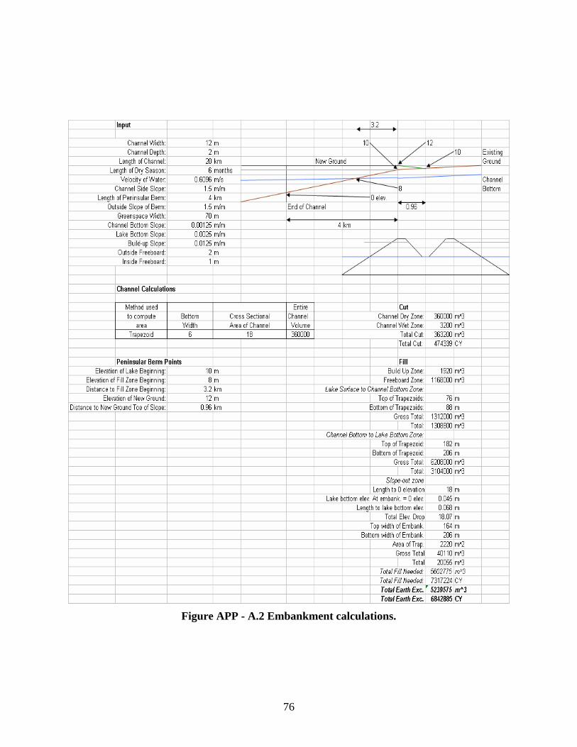
Figure APP - A.2 Embankment calculations.
76

B. Baray
Figure APP - B.1 GIS rendering of site location of East Baray
1200 m from the Western Dike
3000 m from the Western Dike
77

3000 m from the Eastern Dike
1200 m from the Eastern Dike
Figure APP - B.2 Cross-sections at specified locations in the East Baray
Table APP - B.1 Monthly rainfall distribution in Siem Reap.
Month Rainfall(mm)* Jan 6.5 Feb 4.3 March 36.6 April 55 May 188 June 209 July 166 Aug 226 Sept 264 Oct 215 Nov 49.8 Dec 13 Total 1434
*Based on Data from Department of Agriculture From the Mekong River Commission Secretariat “Natural Resources Based Development Strategy for the Tonle Sap Area, Cambodia, 1. Environment in the Tonle Sap Area.” (Table 2, pg. 5):
78

Figure APP - B.3 Typical cross-section of new dike that will divide the East Baray
and allow for water storage in the western two-thirds.
Figure APP - B.4 Design Option 1: Diversion structure at River Siem Reap to fill the
Baray
79

Figure APP - B.5 Schematic of intake structure in River Siem Reap
80

Figure APP - B.6 Location of 4-ft diameter concrete pipeline that will transport
water from the River Siem Reap to the East Baray.
81

Figure APP - B.7 Outlet works to discharge water from the concrete pipeline into
the East Baray
82

Figure APP - B.8 Diagram of stilling basin
Table APP - B.2 Values for stilling basin variables
g 9.806 D1 1.142944 V1 3.74 D2 1.32151 Required Tailwater 1.32151 Froude No. 1.116492 Length Factor (fig 9-42) 3.4 Length 4.493132 m Tailwater Depth 3 m
83

Chute Blocks TW Depth/d1 (fig 9-42) 2.63 d1 1.140684 Dentated Sill TW Depth/d2 1.05 d2 2.857143 s2 0.428571 w2 0.428571 h2 0.571429 Width of basin is arbitrary
Figure APP - B.9 Outlet works to discharge water from the East Baray to the River
84

Figure APP - B.10 Schematic of concrete roadway bridge over spillway
85

Table APP - B.3 Intake pipeline hydraulic calculations worksheet Design of Intake Structure from River Siem Reap to E. Baray
g 9.806 m/s2
Diameter of Feed pipe 4 ft length = 2 mDiameter of Tunnel 1.22 m width = 2 mArea of Tunnel 1.17 m^2 height = 1.5 m
Gate Cd 0.96trashrack
area = 10 m2trash rack on top and 2 sides - not front or back
Manning's n = 0.013 Manning's n = 0.008
ElementLength of Friction (m)
Hydraulic Radius (m)
Area (m^2) (a1/ax)^2 Loss Type Loss Coefficient
(a1/ax)^2 times Coefficient
Loss Coefficient
(a1/ax)^2 times Coefficient
Trashrack Gross 10.0 1.9E-02 Trashrack 0.345 0.007 0.000 0.000Net 8.5
Entrance 3.0 1.5E-01 Entrance 0.200 0.030 0.200 0.0305 2.4 3.0 1.5E-01 Friction 0.008 0.001 0.003 0.000
3.0 1.5E-01 Contraction 0.100 0.015 0.100 0.015Transition 1.2 1.0E+00 Contraction 0.100 0.100 0.100 0.100
0 1.22 1.2 1.0E+00 Friction 0.000 0.000 0.000 0.0001.2 1.0E+00 Contraction 0.100 0.100 0.100 0.100
Upstream Tunnel 1.2 1.0E+00 Contraction 0.100 0.100 0.100 0.100
950 1.22 1.2 1.0E+00 Friction 3.587 3.587 1.358 1.3581.2 1.0E+00 30 deg bend 0.070 0.070 0.070 0.0701.2 1.0E+00 Expansion 0.200 0.200 0.200 0.200
Transition 1.2 1.0E+00 Expansion 0.200 0.200 0.200 0.2000 1.22 1.2 1.0E+00 Friction 0.000 0.000 0.000 0.000
1.2 1.0E+00 Entrance 0.200 0.200 0.200 0.2000 1.22 1.2 1.0E+00 Friction 0.000 0.000 0.000 0.000
1.2 1.0E+00 Contraction 0.100 0.100 0.100 0.100Gates 0.8 2.1E+00 Contraction 0.100 0.209 0.100 0.209
5 0.9 0.8 2.1E+00 Friction 0.028 0.059 0.011 0.0220.8 2.1E+00 Gates 0.085 0.177 0.085 0.1770.8 2.1E+00 Exit 1.000 2.086 1.000 2.086
Total = 7.2420 4.9693
Number of Gates 1.00Width of Gates 1.00Height of Gates 1.00Water Depth just downstream of Gates 0.96Water Surface Elevation at Intake Structure 30Water Surface Elevation in Baray 25.5 max water surface elevation is 29m
Total Head needed to overcome max head loss to produce discharge 3.54Max Flow Rate (max losses) 3.61 m^3/sMax Flow Rate (min losses) 4.36 m^3/s
Max Velocity (max losses) 3.10 m/sMax Velocity (min losses) 3.74 m/s
Dimensions of intake structure
Max Losses Min Losses
86

Table APP - B.4 Outlet works hydraulic calculations worksheet Design of Outlet Works from E. Baray to River Siem Reap
g 9.806 m/s2
Diameter of Feed pipe 4 ft length = 2 mDiameter of Tunnel 1.22 m width = 2 mArea of Tunnel 1.17 m^2 height = 1.5 m
Gate Cd 0.96trashrack
area = 10 m2trash rack on top and 2 sides - not front or back
Manning's n = 0.013 Manning's n = 0.008
ElementLength of Friction (m)
Hydraulic Radius (m)
Area (m^2) (a1/ax)^2 Loss Type Loss Coefficient
(a1/ax)^2 times Coefficient
Loss Coefficient
(a1/ax)^2 times Coefficient
Trashrack Gross 10.0 1.9E-02 Trashrack 0.345 0.007 0.000 0.000Net 8.5
Entrance 3.0 1.5E-01 Entrance 0.200 0.030 0.200 0.0302 2.4 3.0 1.5E-01 Friction 0.003 0.000 0.001 0.000
3.0 1.5E-01 Contraction 0.100 0.015 0.100 0.015Transition 1.2 1.0E+00 Contraction 0.100 0.100 0.100 0.100
0 1.22 1.2 1.0E+00 Friction 0.000 0.000 0.000 0.0001.2 1.0E+00 Contraction 0.100 0.100 0.100 0.100
Upstream Tunnel 1.2 1.0E+00 Contraction 0.100 0.100 0.100 0.100
130 1.22 1.2 1.0E+00 Friction 0.491 0.491 0.186 0.1861.2 1.0E+00 30 deg bend 0.070 0.070 0.070 0.0701.2 1.0E+00 Expansion 0.200 0.200 0.200 0.200
Transition 1.2 1.0E+00 Expansion 0.200 0.200 0.200 0.2000 1.22 1.2 1.0E+00 Friction 0.000 0.000 0.000 0.000
1.2 1.0E+00 Entrance 0.200 0.200 0.200 0.2000 1.22 1.2 1.0E+00 Friction 0.000 0.000 0.000 0.000
1.2 1.0E+00 Contraction 0.100 0.100 0.100 0.100Gates 0.8 2.1E+00 Contraction 0.100 0.209 0.100 0.209
1 0.9 0.8 2.1E+00 Friction 0.006 0.012 0.002 0.0040.8 2.1E+00 Gates 0.085 0.177 0.085 0.1770.8 2.1E+00 Exit 1.000 2.086 1.000 2.086
Total = 4.0977 3.7786
Number of Gates 1.00Width of Gates 1.00Height of Gates 1Water Depth just downstream of Gates 0.96Maximum Baray Water Elevation 29Tunnel Invert at Gates 24
4.04Max Flow Rate (max losses) 5.13 m^3/sMax Flow Rate (min losses) 5.35 m^3/s
Max Velocity (max losses) 4.40 m/sMax Velocity (min losses) 4.58 m/s
Total Head needed to overcome max head loss to produce discharge
Dimensions of intake structure
Max Losses Min Losses
87

Table APP - B.5 Detailed cost breakdown for restoration of E. Baray
rIte
mQu
antity
(SI)
Unit (
SI)Co
nvers
ion Fa
ctoQu
anitit
y (En
gl)Un
it (En
gl)To
tal Co
stMa
terial
Labo
rEq
uipme
ntTo
talTo
tal in
cl. O
verhe
ad an
d Prof
itMa
terial
Labo
rEq
uipme
ntTo
talTo
tal in
cl. O
&PEx
cava
tion
Clay E
xcav
ation
504,6
00,00
0CM
1.308
6016
800
CY0.0
01.3
74.1
45.5
16.6
50.0
01.4
54.3
95.8
57.0
6$4
2,460
,757
New
Dike C
onstr
uctio
nHa
uling,
5 km
5317
2,000
CM1.3
0822
4976
CY0
2.50
4.42
6.92
8.65
2.65
4.69
7.34
9.18
$2,06
5,156
Comp
actio
n48
172,0
00CM
1.308
2249
76CY
00.2
30.5
10.7
40.9
10.2
40.5
40.7
90.9
7$2
17,25
9Ro
adwa
y
Intak
e Pipe
line1.2
2 m D
ia. Co
nc. P
ipe63
1,300
LM3.2
8142
65LF
62.00
22.50
15.20
99.70
120.0
065
.7923
.8816
.1310
5.80
127.3
4$5
43,16
4Ex
cava
tion /
Back
fill49
5,200
CM1.3
0868
02CY
0.00
0.45
0.93
1.38
1.71
0.00
0.48
0.99
1.46
1.81
$12,3
43Ga
tes1
EACH
1.000
1EA
CH10
000.0
010
000.0
010
612.0
810
612.0
8$1
0,612
Stillin
g Bas
in int
o Bara
yCo
ncret
e Slab
20CM
1.308
26CY
77.00
12.45
5.80
18.25
110.0
081
.7113
.216.1
619
.3711
6.73
$3,05
4Co
ncret
e Walls
20CM
1.308
26CY
82.50
48.00
5.75
136.2
517
2.00
87.55
50.94
6.10
144.5
918
2.53
$4,77
5
Outle
t Work
s to R
iver
Conc
rete S
lab3
CM1.3
084
CY77
.0012
.455.8
018
.2511
0.00
81.71
13.21
6.16
19.37
116.7
3$4
58Co
ncret
e Walls
3CM
1.308
4CY
82.50
48.00
5.75
136.2
517
2.00
87.55
50.94
6.10
144.5
918
2.53
$716
1.22 m
Dia.
Conc
. Pipe
6350
LM3.2
8116
4LF
62.00
22.50
15.20
99.70
120.0
065
.7923
.8816
.1310
5.80
127.3
4$2
0,891
Spillw
ayOg
ee W
eir82
.5048
.005.7
513
6.25
172.0
087
.5550
.946.1
014
4.59
182.5
3$0
Stillin
g Bas
inCo
ncret
e Slab
20CM
1.308
26CY
77.00
12.45
5.80
18.25
110.0
081
.7113
.216.1
619
.3711
6.73
$3,05
4Co
ncret
e Walls
20CM
1.308
26CY
82.50
48.00
5.75
136.2
517
2.00
87.55
50.94
6.10
144.5
918
2.53
$4,77
5Br
idge
821,1
00SF
1.000
1100
SF39
.0010
.057.7
056
.7569
.0041
.3910
.678.1
760
.2273
.22$8
0,546
Subto
tal$4
5,427
,560
Conti
ngen
cy, 15
%$6
,814,1
34Lic
ensin
g, 5%
$2,27
1,378
Envir
onme
ntal, 5
%$2
,271,3
78En
ginee
ring,
10%
$4,54
2,756
Total
$61,3
27,20
6
2002
Bare
Costs
2005
Bare
Costs
(ass
uming
2% an
nual
inflat
ion ra
te)
88

C. Mountain Dam
Figure APP - C.1 Graph for weir coefficient determination from crest properties.
89

Figure APP - C.2 Topographical map showing location of mountain dam, reservoir, and
watershed boundry.
DAM
RESERVOIR
WATERSHED BOUNDRY
90

Figure APP - C.3 Detail of heel of dam showing cutoff wall.
Figure APP - C.4 Cross section of embankment showing rockfill zones.
91

Figure APP - C.5 Details of outlet works intake structure.
92

Figure APP - C.6 Details of gate at midway of outlet works.
93

Figure APP - C.7 Spillway profile showing critical water surface, water surface, and chute
bottom.
Figure APP - C.8 Properties of spillway chute at crest (STA. 80.85) under design flood
conditions.
94

Figure APP - C.9 Properties of spillway chute at beginning of widening section (STA. 0)
under design flood conditions.
Figure APP - C.10 Properties of spillway chute at end of widening section (STA. -10.0,
entrance to stilling basin) under design flood conditions.
95

Figure APP - C.11 Stilling basin characteristics for Froude numbers above 4.5.
96

Figure APP - C.12 Typical hydraulic jump stilling basin.
Table APP - C.1 Membrane type decision table. Type of Membrane
Description Pros and Cons Capital Cost
O&M Cost
Central Core
Impervious earth membrane located vertically in the center of the embankment
Pros--protected from the weather, less total area exposed to water; Cons--inaccessible for maintenance/inspection, lower stability
Same More Expensive
Upstream Membrane
Concrete, asphalt, or steel membrane located on the upstream slop of the embankment
Pros--different construction stage, slope protection, higher stability, accessible for maintenance, easy to raise dam, no impervious soil required; Cons--not protected from the weather, larger surface area exposed to water
Same Less Expensive
97

Table APP - C.2 Membrane material decision table. Material Pros and Cons Capital Cost O&M Cost Concrete Pros--wide range of acceptable
gradation, high material availability, experienced construction method; Cons--low settlement toleration
Low Moderate
Asphaltic Concrete
Pros--Can tolerate larger settlements than concrete; Cons--more stringent gradation requirements than concrete, construction must be done more carefully to avoid failure
Moderate Moderate if initial construction is good, high otherwise
Steel Pros--Can tolerate largest settlements, quick construction; Cons--Corrosion reduces economic life, limited material availability leads to higher costs
High Moderate
Table APP - C.3 Spillway type decision table. Type Pros Cons Cost Drop Inlet Medium Easy to design and
construct Low capacity, requires additional auxiliary spillway
Conduit and el ontro
High High capacity, allows great Difficult to maintain Tunn deal of c l
Culvert Easy to desiconstruc
gnt
and Low capacity Low
Side-Chan y,r
construct High nel High capacitvariation ovecrest, easy to
small head weir, long maintain
Difficult to
Chute Easy to design and ct, ada
atteristics
Requires crest bridge Medium construmany foundcharacmaintain
ptable to ion , easy to
Baffled Ch ee s
in already
sign
High ute Eliminates nbasin, saves
d for stilling pace
Stilling basnecessary for outlet works,difficult to de
98

Table APP - C.4 Freeboard requirements by fetch.
ockfill zone properties. Z Permeabi
Table APP - C.5 Rone Gradation Size lity
Z meter = 3 Low one A Well Grated
Max: Diain
5% o. 100
sieve
5% to 1passing N
Zone B Well Grated
Max: 10 ft^3 High
Min: 0 ft^3 Zon
Grated Max: 27 e C Well Moderate
ft^3 Min: 1 ft^ 3
Table APP - C.6 Reservoir elevation-area and elevation-volume. (m ) Area (m^2) Volume Below (m^3) Elevation ) Area (km^2132 0 0 0 140 0.168068 67168068 2272 150 0.990397 990397 6464597 16 8 21560 2.02992 2029928 6222 170 3.225423 3225423 47842977 180 4.532232 4532232 86631252
190* 9.109798 154849109798 1402 191.5 9.986047 6329986047 1691 85.8
Total Reservoir Volume Below Spillway = 154841402
ay * Elevation of Spillw
99

Table APP - C.7 Outlet works calculation worksheet.
g 9.81 m/s^2Diameter of Tunnel 0.85 m 2.788 33.46Area of Tunnel 0.5671625 m^2Wetted Perimeter 2.669 mGate Cd 0.96
Manning's n = 0.013 Manning's n = 0.008
ElementLength of Friction (m)
Hydraulic Radius (m)
Area (m^2) (a1/ax)^2 Loss Type
Loss Coefficient
(a1/ax)^2 times Coefficient Loss Coefficient
(a1/ax)^2 times Coefficient
Trashrack Gross 4.0 0.04 Trashrack 0.550 0.020 0.000 0.000Net 3.0
Entrance 1.0 0.32 Entrance 0.200 0.064 0.200 0.0643.05 0.5 1.0 0.32 Friction 0.038 0.012 0.014 0.005
1.0 0.32 Contraction 0.100 0.032 0.100 0.032
Upstream Tunnel 0.6 1.00 Contraction 0.100 0.100 0.100 0.10058.65 0.2125 0.6 1.00 Friction 2.275 2.27
Table X.XComputation of Outlet Works Loss Coefficients and Flow Rates
500
0.861 0.8610.6 1.00 30 deg bend 0.070 0.07 0.070 0.0700.6 1.00 Expansion 0.200 0.20 0.200 0.200
Gates 2.0 0.08 Contraction 0.100 0.008 0.100 0.0089.3 9 0.044 0.004
7 0.085 0.0070 1.000 0.080
Downstream Tunnel .10 0.100 0.1005 25 0.6 27 2.275 0.861 0.861
0.6 .200 0.200 0.200 0.2005.452 1.431299263
efficient = 0.43 0.84
0.5 2.0 0.08 Friction 0.115 0.002.0 0.08 Gates 0.085 0.002.0 0.08 Exit 1.000 0.08
0.6 1.00 Contraction 01.00 Friction 2.1.00 Expansion 0
0 0.1008.65 0.21 5
Total =HEC orifice coAverage orifice coefficient 0.63
Number of Gates 1Width of Gates 1.00Height of GatesWater Depth just downstream Maximum Reservoir ElevationTunnel Invert at Gates
Max Flow Rate (max losses) 3/s Adju til this meets necessary flowsMax Flow Rate (min losses) 15.58 m^3/s Use t stilling basinAverage Flow Rate 11.78 m^3/sMaximum Velocity 27.48 m/s
Total Head needed to overcommax head loss to produce discharge
Max Losses Min Losses
=
21.92190133
of Gates
55.087.98 m^ st above worksheet un
his value to design
e
Table APP - C.8 Stilling basin w sheet. Pre-Stilling Basin
ork
Flow from OWorks 1 3/s
utlet 5.51 m
Flow from S 1 3/spillway 50.00 mTotal Flow 1 3/s65.51 mArea 3/s8.27 mVelocity /s 20.01 mStilling Bas in g 9.81 m/s2
Width 10.00 m D1 0.83 m V1 20.01 m/s D2 7.83 m Required Tailwater 139.33 m Froude No. 7.01 Length Factor (fig 9-42) 4.15 Length 32.48 m
100

Freeboard 2.78 m Tailwater Depth 2.00 m Chute Blocks TW Depth/d1 (fig 9-42) 10.00 d1 0.20 m # of blocks 25 Dentated Sill TW Depth/d2 1.05 d2 1.90 m s2 0.29 m w2 0.29 m h2 0.38 m # of sill blocks 18 L/d2 (fig 9-42) 4.35 length of jump itself 8.29 m
101

Table APP - C.9 Detailed cost b
reakdown of dam.
Item
Quan
tity
(SI)
Unit
(SI)
Conv
ersi
on
Fact
orQu
aniti
ty
(Eng
l)Un
it (E
ngl)
Tota
l Cos
t
Mat
eria
lLa
bor
Equi
pmen
tTo
tal
Tota
l inc
l. Ov
erhe
ad a
nd
Prof
itM
ater
ial
Labo
rEq
uipm
ent
Tota
lTo
tal i
ncl.
Over
head
an
d Pr
ofit
Dive
rsio
n1
EACH
1.00
01
EACH
1500
000.
0015
0000
0.00
1591
812.
0015
9181
2.00
1591
812
Emba
nkm
ent
Rock
Exc
avat
ion
2310
000
CM1.
308
3021
480
CY1.
805.
837.
6615
.28
19.3
81.
91Ha
ulin
g, 5
km
2310
000
CM1.
308
3021
480
CY1.
042.
613.
654.
45Co
mpa
ctio
n23
1000
0CM
1.30
830
2148
0CY
0.43
1.25
1.68
2.02
78Br
idge
35SM
10.7
6037
7SF
39.0
010
.05
7.70
56.7
569
.00
41.3
960
.22
Road
way
7791
SM1.
196
9318
SY7.
130.
690.
858.
679.
847.
579.
20
Out
let W
orks
.85
m D
iam
eter
Pip
e16
2LM
3.28
153
1LF
31.2
518
.00
9.15
58.4
072
.25
33.1
661
.97
67G
ates
1EA
CH1.
000
1EA
CH10
000.
0010
000.
0010
612.
0810
612.
08
Spillw
ay0
Oge
e W
eir
182
CM1.
308
238
82.5
048
.00
5.75
136.
2517
2.00
87.5
6.10
144.
5918
2.53
12Co
ncre
te S
lab
49CM
1.30
864
CY77
.00
12.4
55.
8095
.25
110.
0081
.71
13.2
16.
1610
1.08
116.
7374
36Co
ncre
te W
alls
368
CM1.
308
482
CY82
.50
48.0
05.
7513
6.25
172.
0087
.55
50.9
46.
1014
4.59
182.
5387
906
Stilli
ng B
asin
Conc
rete
Sla
b33
CM1.
308
43CY
77.0
012
.45
5.80
95.2
511
0.00
81.7
16.
111
6.73
5039
Conc
rete
Wal
ls67
CM1.
308
87CY
82.5
048
.00
5.75
136.
2517
2.00
87.5
51
1594
8
Rese
rvoi
r Pre
para
tion
1EA
CH1.
000
1EA
CH20
0000
.00
2000
00.0
00.
000.
000.
0021
2241
.60
2122
41.6
021
2242
Inst
rum
enta
tion
1EA
CH1.
000
1EA
CH15
0000
.00
1500
00.0
015
9181
.20
1591
81
Subt
otal
8516
9135
Cont
inge
ncy,
15%
1277
5370
Lice
nsin
g, 5
%42
5845
7En
viron
men
tal,
5%42
5845
7En
gine
erin
g, 1
0%85
1691
4To
tal
1149
7833
2
2002
Bar
e Co
sts
2005
Bar
e Co
sts
(ass
umin
g 2%
ann
ual i
nfla
tion
rate
)
6.18
1.10
0.46
10.6
70.
73
19.1
0
0.94
8.12
2.77
1.33
8.17
0.90
9.71
1 1.6.22
3.87
20 4. 2. 73 10 76..5
672 14 .2
2.4
4
6212
1426
6476
927 97
30
40 10
043
54363
8563 66
576 2
678
612
55 13
.21
50.9
46
101.
0814
4.59
6.10
82.5
3
1591
81.2
0
102

D. General
Figure APP - D.1 The temple of Angkor Wat, the primary tourist attraction in the area.
103

Figure APP - D.2 The Siem Reap Master Plan, courtesy of Professor Hackchul Kim.
104

Figure APP - D.3 Overhead view of (partially) scaled model of area.
105

Figure APP - D.4 Flow chart of proposed hydraulic system.
106

E. Schedule
Figure APP - E.1 Condensed fall schedule.
Figure APP - E.2 Condensed spring schedule.
107

F. Budget Table APP - F.1 Team budget.
108


![Wrangling the [Biblio] Module](https://static.fdocuments.in/doc/165x107/568162e7550346895dd36959/wrangling-the-biblio-module.jpg)


