Water Treatment with Reverse Osmosis Technology · quires water of extremely low conductivity i.e....
12
Water Treatment with Reverse Osmosis Technology
Transcript of Water Treatment with Reverse Osmosis Technology · quires water of extremely low conductivity i.e....

Water Treatmentwith Reverse Osmosis Technology

TEMAK is a leading Greek manufacturing company in the water treatment industry since 1972, operating in the domestic and foreign markets. Our mission is to keep our customers satisfied offering fully integrated water solutions, designed and manufactured according to their customers’ needs.
The structure and operation of TEMAK is based on the most up-to-date management techniques and practices, so as to promptly and efficiently respond to every need of each customer.
We can be your Reverse Osmosis (RO) ideal partner!
• The ideal solutions are designed from the very beginning based exclusively upon the special needs and require-ments of each customer
• These solutions are integrated on a highly professional ba-sis, at all project stages: Design, manufacturing, installation and after sales support
• High quality services are provided, regardless of the size of the project we are working on
Based on these principles, TEMAK studies, designs, manu-factures, installs and supports the proper solution that fits exactly in each specific situation. Besides our know-how, our everyday close contact and service to the market is a major point of our offering. This constitutes the basis of our performance and on this basis we gain our customers’ trust, because we understand very well their needs, there-fore, we can demonstrate the benefit of the solution.
TEMAKPROVIDES
• Scientific and technical personnel with many years of experience
• Surveys, studies and investment proposals• High quality construction with the best construction
materials and components• Well organized, fast and efficient service
• Continuous stock of spare parts• Modern facilities and infrastructure• Reference list with numerous satisfied customers• Guarantee• Customization
Premises 5.000 m2 in Acharnes (Menidi), Athens, Greece

Due to the global increase of impure water, the fastest and most applied widely method of modernwater treatment is the Reverse Osmosis.
But what is Reverse Osmosis?
Principle of Reverse Osmosis (RO)
03
Osmosis
Low Concentration
Solution
Low Concentration
Solution
Low Concentration
Solution
High Concentration
Solution
High Concentration
Solution
High Concentration
Solution
Semi-Permeable Membrane
Semi-Permeable Membrane
Osmotic Pressure
Semi-Permeable Membrane
Reverse Osmosis
Reverse Osmosis
Pressure
OsmosisWhen two solutions of different concentration are separated with a semi-permeable membrane, pure water is transferred through the membrane from the lower to the higher concentration solution (osmotic flow).
The osmotic flow continues until an equilibrium is achieved, where the level of the higher concentration solution settles at a level higher than the initial one. The difference between the levels of the two solutions causes the so-called osmotic pressure.
Reverse Osmosis Reversing the process, if an external pressure greater than the osmotic pressure is applied on the higher concentration solution, pure water is transferred through the membrane towards the low concentration solution.This process is called Reverse Osmosis.
Food & Beverages
Water Bottling
Spin, Textile & Dyeing Houses
Paper Industry
Chemical Industry
Metallurgy & Aluminium
Pharma & Cosmetics
Semiconductor Industry
Photovoltaic Solar Panels
Fish Farms
Washing Stations
Green Houses
Hotels & Tourist Villages
Buildings & Residential
Restaurants & Kitchens
Hospitals
Hemodialysis Centers
Power Plants
Laboratories
Marine
Municipalities
Potable Water Production
BoilersFeedWater
IrrigationDeionization forthe Applications
Demands
Final Stageof BiologicalTreatment
Network /Equipment
Protection fromScaling
Ultra-PureWater
Production
IceProductionSectors
Applications

• High pressure pipes of TBW 21 up to TBW 28 for high brackish water are made of stainless steel duplex SAF 2205 & 316Ti
• Electronic control panel, separate from the main electric switchboard, with user friendly mimic diagram of the pro-cess, provides all necessary information for every part's operation and functions at low voltage 24V for safe infor-mation
• Recovery and absorbed power for brackish water RO sys-tems depend on the quality (ppm TDS) and temperature of the raw water
Brackish Water RΟ Units
Max Production(m3/24hrs)
Model
TBW 315
TBW 316
TBW 318
TBW 320
ΤBW 324
TBW 330
TBW 336
TBW 340
432.0
451.2
528.0
588.0
720.0
900.0
1080.0
1248.0
Model Max Production(m3/24hrs)
TBW 11
TBW12
TBW 21
TBW 22
TBW 23
TBW 24
TBW 25
TBW 26
ΤBW 28
2.4
4.8
7.2
13.9
19.9
25.2
30.2
39.8
50.4
Max Production(m3/24hrs)
Model
TBW 32
TBW 33
TBW 34
TBW 36
TBW 38
TBW 39
TBW 310
TBW 312
67.2
100.8
127.2
177.6
225.6
276.0
302.4
345.6
TBW 2 TBW 3
! Complete Water Treatment Systems for Haemodialysis Centers certified according to Annex V of theMedical Device Directive 93/42/EEC
TBW 1
On Request• Mobile desalination stations ergonomically installed in
steel containers with sound and thermal insulation• Custom-made desalination plants designed according to
customers specifications• Instrumentation’s output signal transmition to a control
room or to a PC for remote supervision (SCADA). Auto-matic notifications on your mobile phone in case of a sys-tem alarm

Sea Water RO Units
TSW 1 MARINE TSW 3 MARINETSW 2
ModelMax Production
(m3/24hrs)Nominal
Power (kw)Energy
(kWh/m3)Recovery
%
TSW 01
TSW 02
TSW 03
TSW 11
TSW 12
TSW 13
TSW 14
TSW 16
TSW 18
TSW 19
TSW 22
TSW 23
TSW 24
TSW 26
TSW 24A
TSW 26A
TSW 28A
TSW 32SP
TSW 32
TSW 33SP
TSW 33
TSW 34SP
TSW 34
TSW 36
TSW 38
TSW 312
TSW 316
TSW 324
0.84
1.68
2.4
2.1
4.1
5.7
6.9
9.1
10.6
11.0
10.5
14.4
17.7
22.0
21.1
28.8
33.6
33.6
38.4
44.2
52.8
57.6
64.8
79.2
105.6
158.4
211.2
316.8
1.8
1.8
1.8
2.2
2.2
2.2
2.2
2.2
2.2
2.2
7.5
7.5
7.5
7.5
15.0
15.0
15.0
15.0
18.5
15.0
18.5
15.0
18.5
18.5
22.0
37.0
44.0
66.0
42.8
21.4
15
30.3
16.4
11.7
9.5
7.4
6.5
6.2
13.6
9.8
8.0
6.3
13.6
9.8
8.1
9.2
10.7
6.9
7.9
5.7
6.5
5.3
5.2
5.3
5.2
5.2
5.8
11.7
16.7
9.0
17.0
24.0
29.0
38.0
44.0
46.0
17.6
24.0
29.6
36.8
17.6
24.0
28.0
22.0
20.0
28.7
27.5
37.5
34.0
41.0
43.0
41.0
43.0
43.0
ModelMax Production
(m3/24hrs)Nominal
Power (kw)Energy
(kWh/m3)Recovery
%
TSW 324HP
TSW 332HP
TSW 340HP
TSW 348HP
TSW 356HP
TSW 364HP
TSW 38PX
TSW 310PX
TSW 314PX
TSW 316PX
TSW 324PX
TSW 332PX
TSW 340PX
TSW 348PX
TSW 356PX
TSW 364PX
381
509
636
763
890
1021
127
153
211
262
381
509
636
763
890
1021
75.0
90.0
110.0
132.0
160.0
200.0
20.6
24.1
25.8
38.5
59.5
76.5
97.0
117.0
132.0
172.0
4.4
4.2
4.1
3.5
3.5
3.6
3.0
3.1
2.8
2.8
2.8
2.8
2.8
2.8
2.8
2.8
42
42
44
42
42
42
42
42
42
42
42
42
42
42
42
44
Units With Energy Recovery Device
05
On Request• Mobile desalination stations ergonomically installed in
steel containers with sound and thermal insulation• Custom-made desalination plants designed according to
customers specifications• Instrumentation's output signal can be transmitted to a
control room or to a PC for remote supervision (SCADA). Automatic notification on your mobile phone in case of a system alarm
• Marine type desalination systems, specially designed for the vessels' restricted space
• Max production flow rate and energy consumption are calculated for TDS = 42,000 ppm, Temp = 200 C and foul-ing factor = 0.85
• High pressure piping by duplex stainless steel SAF 2507. • High pressure pump by super duplex stainless steel
SAF 2507• Pressure Exchangers for specific power consumption
2.8 kWh/m3 of product water
• Electronic control panel, different than the main electric power switchboard, with user friendly mimic diagram of the process, provides all necessary info for every part's op-eration and functions at low voltage 24V for safe operation
• The specific energy consumption depends on the feed-water quality (ppm TDS) and temperature. It is calculated separately in each application

C.I.P. andFlush Tank
Feed Water To Tank
Feed Water Tank
Turbidity Filters Drain Tank
Drainage
Safety Filters
Energy Recovery System (PX)
Power Panel
High Pressure
Pump
Product Water300 m3/day
1st Pass Pressure Pumps
High Pressure Pumps of 2nd Pass RO
2nd Pass of Reverse Osmosis
CIP Pump
2nd Pass RODrain
Flush Tank of 1st Pass
RO
Feed Water Tank of 1st Pass Reverse Osmosis
Dosing System
Ultra Filtration System
RawWater
Feed Pumps
300 m3/day water for general use - Mobile Containerized Sea Water Reverse Osmosis Systemwith Energy Recovery (TDS = 55,000 ppm)

Drainage
1st Pass of Reverse Osmosis
Membrane Degasser System
Continuous Electrodeionization
System (CEDI)
Feed Tank
Product Water
07
Feed Water Tank
Turbidity Filters
Filter Water Safety Filters
Drain Tank
Drainage
CIP Pump
CIP andFlush Tank
Energy RecoverySystem
High Pressure Pumps
ProductWater
ElectricalPanel
Feed Pumps
600 m3/day water for general use - Mobile Sea Water Reverse Osmosis Systemwith Energy Recovery (TDS = 55,000 ppm)
1,200 m3/day Ultrapure Water to Feed Boilers in Power Plant Mobile Containerized Brackish Water Reverse Osmosis System
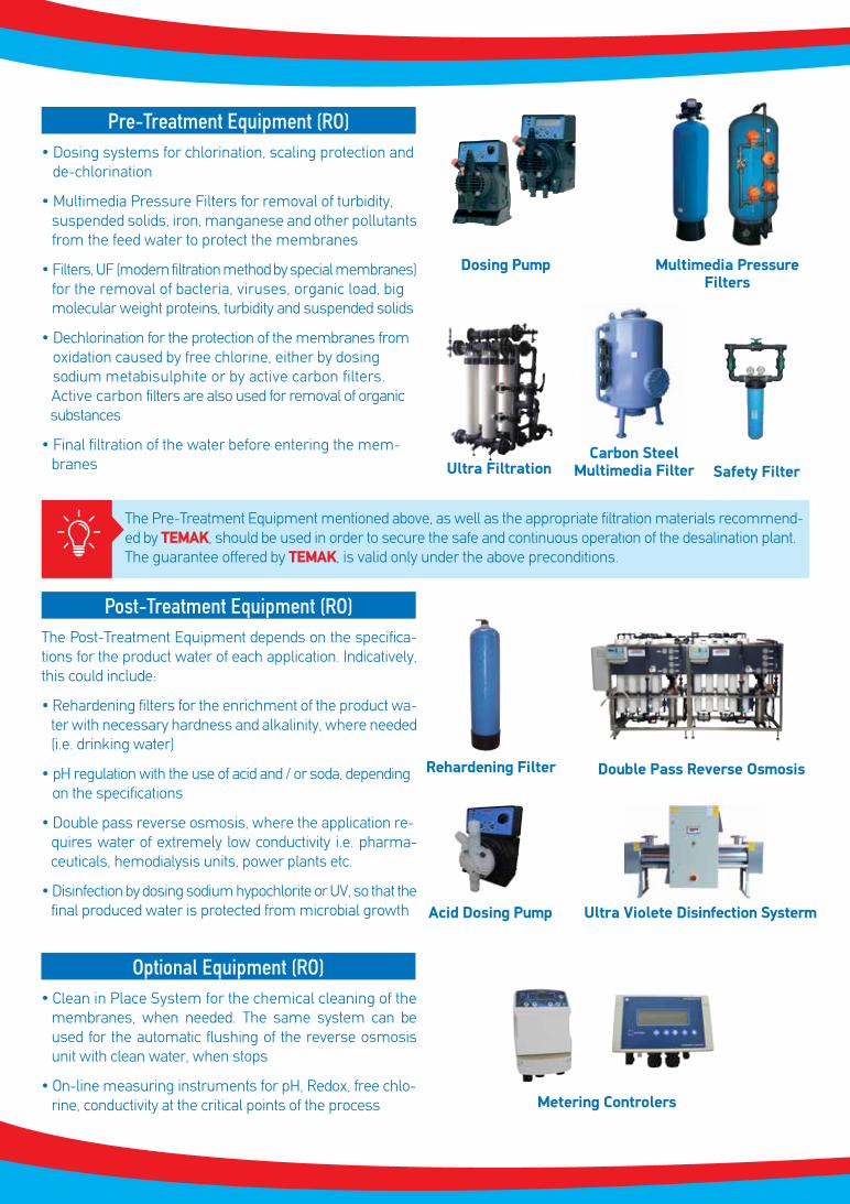
Pre-Treatment Equipment (RO)• Dosing systems for chlorination, scaling protection and de-chlorination
• Multimedia Pressure Filters for removal of turbidity,suspended solids, iron, manganese and other pollutants from the feed water to protect the membranes
• Filters, UF (modern filtration method by special membranes)for the removal of bacteria, viruses, organic load, big molecular weight proteins, turbidity and suspended solids
• Dechlorination for the protection of the membranes from oxidation caused by free chlorine, either by dosing sodium metabisulphite or by active carbon filters. Active carbon filters are also used for removal of organic substances
• Final filtration of the water before entering the mem-branes
Post-Treatment Equipment (RO)The Post-Treatment Equipment depends on the specifica-tions for the product water of each application. Indicatively, this could include:
• Rehardening filters for the enrichment of the product wa-ter with necessary hardness and alkalinity, where needed (i.e. drinking water)
• pH regulation with the use of acid and / or soda, depending on the specifications
• Double pass reverse osmosis, where the application re-quires water of extremely low conductivity i.e. pharma-ceuticals, hemodialysis units, power plants etc.
• Disinfection by dosing sodium hypochlorite or UV, so that thefinal produced water is protected from microbial growth
Optional Equipment (RO)• Clean in Place System for the chemical cleaning of the
membranes, when needed. The same system can be used for the automatic flushing of the reverse osmosis unit with clean water, when stops
• On-line measuring instruments for pH, Redox, free chlo-rine, conductivity at the critical points of the process
Rehardening Filter Double Pass Reverse Osmosis
Dosing Pump Multimedia PressureFilters
Ultra FiltrationCarbon Steel
Multimedia Filter Safety Filter
Acid Dosing Pump Ultra Violete Disinfection Systerm
Metering Controlers
The Pre-Treatment Equipment mentioned above, as well as the appropriate filtration materials recommend-ed by TEMAK, should be used in order to secure the safe and continuous operation of the desalination plant. The guarantee offered by TEMAK, is valid only under the above preconditions.

Monitoring The RO OperationTEROC is a software developed exclusively by TEMAK to monitor the operation and efficiency of any water desalina-tion plant, using the method of Reverse Osmosis.
TEROC can electronically record, print, calculate and create graphs of the:
• Feed water quality• Drop of pressure across the RO membranes • Duration of the RO operation• Aging of the membranes through the normalization of
the permeate water flow rate and the salts’ passage
Controlling the RO SystemThe RO-T4F panel controls the Reverse Osmosis System and its main characteristics are:
• Automation and Control System for Reverse Osmosis Water Treatment Plants
• Low Voltage Panel (24VAC) - Separate from the electrical panel - User Safety
• Menu in two languages, English and Greek• Communication through four lines display and through
mimic diagram on the panel front view• Possibility of connection with a PC (for remote monitoring)• Connection to GSM• Ability to update with a message to up to three phone
numbers if alarm occurs
09
ADVANTAGES• Modern and advanced design,
custom-made solutions• Excellent quality of construction
materials• Automatic multimedia pressure
filters, specific to each system• Low energy consumption
• Low cost of operation• Design adapted to available space• Automatic and control systems by
PLC and option of remote controlof the plant (SCADA)
• Timely and immediate technical support
Samples of the graphs are shown below:
Product Water Conductivity
Date
Cond
ucti
vity
μS/
cm
250
200
150
100
50
0
28/4/07 14/11/07 1/6/08 18/12/08 6/7/09 22/1/10 10/8/10 26/2/11
Pressure Drop at the RO membranes
Pres
sure
Dro
p, b
ar
9,0
8,0
7,0
6,0
5,0
4,0
3,0
2,0
1,0
0,028/4/07 14/11/07 1/6/08 18/12/08 6/7/09 22/1/10 10/8/10 26/2/11
Date

Complete Reverse Osmosis Systems (RO)
• The reject water quantity and absorbed power depend on the quality (TDS) and temperature of the feed water. Exclusive design, manufacturing and assembly by spe-cialized personnel
• Desalination units completely pre-fabricated and fully tested for operation and control, ready to be installed and set in operation
• High quality materials used• Reliability and guaranteed efficiency• Easy installation and space saving• Minimal cost of installation and operation
SYTBW 1 SYTBW 2 SYTBW 3
Note: Pre-treatment filters are not included and selected according to each project specifications (concerning SYTBW3 & SYTSW3 models)
Model Max Production(m3/24hrs)
Brackish Water
SYTBW 11
SYTBW 12
SYTBW 21
SYTBW 22
SYTBW 23
SYTBW 24
SYTBW 25
SYTBW 26
SYTBW 28
SYTBW 32*
SYTBW 33*
SYTBW 34*
SYTBW 36*
SYTBW 38*
2.4
4.8
7.2
13.9
19.9
25.2
30.7
39.8
50.4
67.2
100.8
127.2
177.6
225.6
Sea Water
Max Production(m3/24hrs)
Model
SYTSW 11
SYTSW 12
SYTSW 13
SYTSW 14
SYTSW 16
SYTSW 18
SYTSW 19
SYTSW 22
SYTSW 23
SYTSW 24
SYTSW 26
SYTSW 32*
SYTSW 33*
SYTSW 34*
SYTSW 36*
SYTSW 38*
21.
4.1
5.7
6.9
9.12
10.56
11.04
10.5
14.4
17.7
22.0
38.4
52.8
64.8
79.2
105.6
Note: Brackish Water Systems are offered with the option of blending the permeate water from the Reverse Osmosis Unit with of feed water

TEMAK’s Ιndicative Ιnstallations
11
Power PlantCapacity: 960 m3/dayFeed Water Quality: Sea WaterProduct Water Quality: 300μS/cm
MunicipalityCapacity: 1.800 m3/dayFeed Water Quality: Sea WaterProduct Water Quality: Potable
HospitalProduction: 35 m3/dayFeed Water Quality: NetworkProduct Water: Hemodialysis Standards
MunicipalityCapacity: 2.000 m3/dayFeed Water Quality: Sea WaterProduct Water Quality: Potable
Power Plant - RO with Electrodeionization System (CEDI)Capacity: (2 x 243) m3/dayFeed Water Quality: Brackish WaterProduct Water Quality: Ultrapure Water to Feed Boilers
ResidenceCapacity: 125 m3/dayFeed Water Quality: Sea WaterProduct Water Quality: Potable
PharmaceuticalCapacity: 4 m3/hFeed Water Quality: Brackish WaterProduct Water Quality: Ultrapure
HotelCapacity: 500 m3/dayFeed Water Quality: Sea WaterProduct Water Quality: Potable

“Experts in Processing Water”