Water treatment and water disinfection 2018 - ProMinent · Water Treatment and Water Disinfection....
190
2018
Transcript of Water treatment and water disinfection 2018 - ProMinent · Water Treatment and Water Disinfection....
2018

GermanyPhone +49 622
www.prominen
1 842–0
t.com
Product Catalogue Volume 4
1.0.1www.prominent.comProduct Catalogue Volume 4
A clear case of disinfectionHygienically pure water is one of the greatest challenges of our time. With ProMinent® products and systems - combined with our many years of practical experience - we have developed application-based solutions for a range of different industries. They are characterised by their outstanding handling of natural resources, minimal operating costs and maximum efficiency.Chapter 1 offers UV systems for the gentle and chemical-free disinfection of water. They are ideal for applications associated with the treatment of potable water or swimming pool water, as well as in the beverage industry.Refer to Chapter 2 for the effective removal of undesirable organic and inorganic substances or for efficient disinfection in the treatment of cooling and process water. The chapter focuses on ozone systems with the most diverse capacity ranges. Choose from this diverse product range for a trouble-free outcome - advice included!Avoid undesired by-products that occur with standard disinfection with chlorine. To this end, refer to chapter 3 for economically and ecologically sensitive alternative disinfection methods with chlorine dioxide.Chapter 4 describes electrolysis systems, precisely the right alternative for ultra-environmentally-friendly applications, for example instead of chlorine gas.Metering systems for chlorine gas DULCO®Vaq in chapter 5 enable high germ destruction speed with low operating costs. Their vacuum technology ensures maximum operating safety.The storage tanks from chapter 6 are indispensable. They comply with internationally applicable manufacturing approvals and are suitable for installation outdoors and indoors.The metering systems Ultromat® are persuasive with their ease of assembly and operation. They meet the ultimate requirements in terms of the separation of colloidal solids from liquids. They can be found in Chapter 7.When it comes to the reliable removal of particles and salts, we recommend systems with membrane filter technology described in Chapter 8.
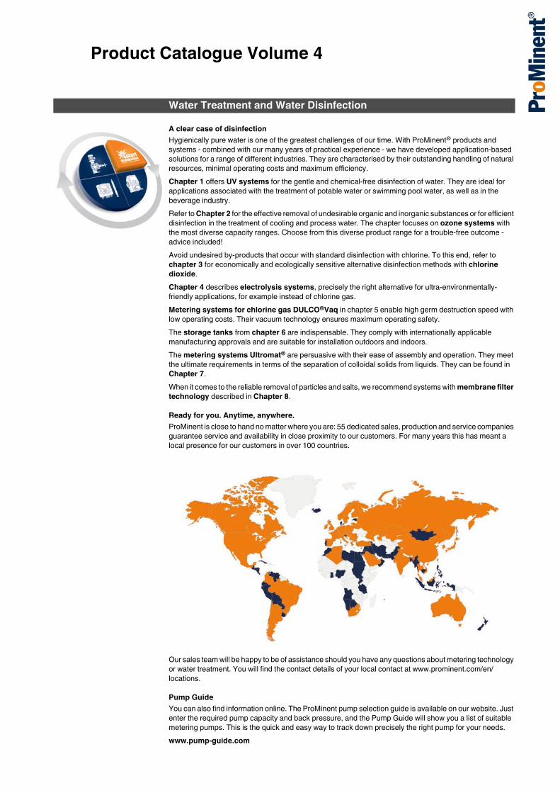
Ready for you. Anytime, anywhere.ProMinent is close to hand no matter where you are: 55 dedicated sales, production and service companies guarantee service and availability in close proximity to our customers. For many years this has meant a local presence for our customers in over 100 countries.
Our sales team will be happy to be of assistance should you have any questions about metering technology or water treatment. You will find the contact details of your local contact at www.prominent.com/en/locations.
Pump GuideYou can also find information online. The ProMinent pump selection guide is available on our website. Just enter the required pump capacity and back pressure, and the Pump Guide will show you a list of suitable metering pumps. This is the quick and easy way to track down precisely the right pump for your needs.www.pump-guide.com
Water Treatment and Water Disinfection

New Products
1.0.1www.prominent.com1New Products.
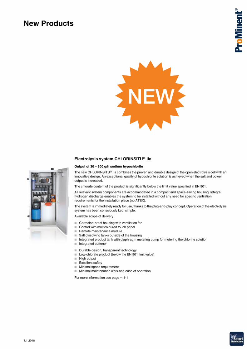
Electrolysis system CHLORINSITU® IIaOutput of 30 – 300 g/h sodium hypochloriteThe new CHLORINSITU® IIa combines the proven and durable design of the open electrolysis cell with an innovative design. An exceptional quality of hypochlorite solution is achieved when the salt and power output is increased.The chlorate content of the product is significantly below the limit value specified in EN 901.All relevant system components are accommodated in a compact and space-saving housing. Integral hydrogen discharge enables the system to be installed without any need for specific ventilation requirements for the installation place (no ATEX).The system is immediately ready for use, thanks to the plug-and-play concept. Operation of the electrolysis system has been consciously kept simple.Available scope of delivery:� Corrosion-proof housing with ventilation fan� Control with multicoloured touch panel� Remote maintenance module� Salt dissolving tanks outside of the housing� Integrated product tank with diaphragm metering pump for metering the chlorine solution� Integrated softener� Durable design, transparent technology� Low-chlorate product (below the EN 901 limit value)� High output� Excellent safety� Minimal space requirement� Minimal maintenance work and ease of operationFor more information see page → 1-1
1.1.2018
New Products
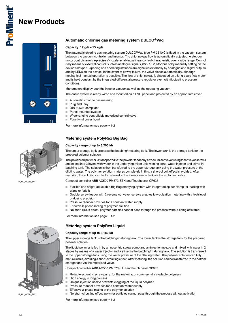
Automatic chlorine gas metering system DULCO®VaqCapacity: 12 g/h – 15 kg/hThe automatic chlorine gas metering system DULCO®Vaq type PM 3610 C is fitted in the vacuum system between the vacuum controller and injector. The chlorine gas flow is automatically adjusted. A stepper motor controls an ultra-precise V-nozzle, enabling a linear control characteristic over a wide range. Control is by means of external control, such as analogue signals, 0/2 - 10 V, Modbus or by manually setting on the device’s keypad. Opening and operating statuses are signalled externally by analogue and digital outputs and by LEDs on the device. In the event of power failure, the valve closes automatically, although mechanical manual operation is possible. The flow of chlorine gas is displayed on a long-scale flow meter and is held constant by the integrated differential pressure regulator even with fluctuating pressure conditions.Manometers display both the injector vacuum as well as the operating vacuum.The entire system is ready-wired and mounted on a PVC panel and protected by an appropriate cover.� Automatic chlorine gas metering� Plug and Play� DIN 19606-compliant� Panel-mounted system� Wide-ranging controllable motorised control valve� Functional cover hoodFor more information see page → 1-2
Metering system PolyRex Big BagCapacity range of up to 8,200 l/hThe upper storage tank prepares the batching/ maturing tank. The lower tank is the storage tank for the prepared polymer solution.The powdered polymer is transported to the powder feeder by a vacuum conveyor using 2 conveyor screws and mixed into 3 layers with water in the underlying mixer unit; wetting cone, water injector and stirrer in batching tank. The solution is then transferred to the upper storage tank using the water pressure of the diluting water. The polymer solution matures completely in this, a short circuit effect is avoided. After maturing, the solution can be transferred to the lower storage tank via the motorised valve.Compact controller ABB AC500 PM573-ETH and Touchpanel CP635� Flexible and height-adjustable Big Bag emptying system with integrated spider clamp for loading with
crane or forklift� Double-screw feeder with 2 reverse conveyor screws enables low-pulsation metering with a high level
of dosing precision� Pressure reducer provides for a constant water supply� Effective 3-phase mixing of polymer solution� No short circuit effect, polymer particles cannot pass through the process without being activatedFor more information see page → 1-2
Metering system PolyRex LiquidCapacity range of up to 3,180 l/hThe upper storage tank is the batching/maturing tank. The lower tank is the storage tank for the prepared polymer solution.The liquid polymer is fed in by an eccentric screw pump and an injection nozzle and mixed with water in 2 stages by means of a water injector and a stirrer in the batching/maturing tank. The solution is transferred to the upper storage tank using the water pressure of the diluting water. The polymer solution can fully mature in this, avoiding a short-circuiting effect. After maturing, the solution can be transferred to the bottom storage tank via the motorised valve.Compact controller ABB AC500 PM573-ETH and touch panel CP635� Reliable eccentric screw pump for the metering of commercially available polymers� High energy mixing process� Unique injection nozzle prevents clogging of the liquid polymer� Pressure reducer provides for a constant water supply� Effective 2-phase mixing of the polymer solution� No short-circuiting effect: polymer particles cannot pass through the process without activationFor more information see page → 1-2
P_UL_0039_SW
P_UL_0038_SW
1-2 1.1.2018
1.1.2018
Contents
Water Treatment and Water Disinfection page
1 UV Systems Dulcodes 1-11.1 General Notes on UV Treatment 1-11.1.1 Applications of Dulcodes UV Systems 1-11.1.2 Description of Dulcodes UV Systems 1-2
1.2 Performance Overview of Dulcodes UV Systems 1-41.2.1 Notes on Planning and Designing an UV System 1-5
1.3 Questionnaire for Designing an UV System 1-61.4 UV System Dulcodes LP 1-71.5 UV system Dulcodes LP certified 1-91.6 UV System Dulcodes LP-PE Plastic 1-111.7 UV System Dulcodes MP 1-131.8 UV System Dulcodes A 1-151.9 Accessories for Dulcodes UV Systems 1-17
2 Ozone Systems OZONFILT® 2-12.1 Ozone In Water Treatment 2-12.2 Performance Overview of Ozone Systems 2-22.3 Questionnaire on the Design of an Ozone System 2-32.4 Ozone System OZONFILT®OZVa 2-4
2.4.1 OZONFILT® OZVa 1-4 Ozone Generation Systems (Process Gas - Air) 2-5
2.4.2 OZONFILT® OZVa 5-7 Ozone Production Systems (Operating Gas - Oxygen) 2-7
2.4.3 System Solution OZONFILT® Compact OMVa 2-112.5 Ozone System OZONFILT® OZMa 2-13
2.5.1 Ozone Generation Systems OZONFILT® OZMa 1-6 A (Operating Gas - Air) 2-15
2.5.2 Ozone Generation Systems OZONFILT® OZMa 1-6 O (Operating Gas - Oxygen) 2-18
2.5.3 Ordering Information for OZONFILT® OZMa Systems 2-212.6 Accessories and Spare Parts for Ozone Systems 2-22
2.6.1 Compressors for OZONFILT® OZVa 1-4 2-222.6.2 Oxygen generator for OZONFILT® OZVa 5-7 and OZMa10 2-232.6.3 Static Helical Mixer Made of PVC or Stainless Steel 2-242.6.4 Accessories for OZONFILT® OZMa 2-252.6.5 Bleed Valves 2-252.6.6 Residual Ozone Gas Destructor 2-252.6.7 Room Air Monitoring 2-262.6.8 Cooling Water Heat Exchanger 2-272.6.9 Personal Protection Accessories 2-282.6.10 Overvoltage Protection 2-282.6.11 Replacement Plug-in Insert After Tripping 2-28
3 Bello Zon® Chlorine Dioxide Systems 3-13.1 Chlorine Dioxide in Water Treatment 3-1
3.1.1 Chlorine Dioxide Applications 3-13.1.2 Bello Zon® System Technology 3-2
3.2 Performance Overview of Chlorine Dioxide Systems 3-33.3 Questionnaire on the Design of a Chlorine Dioxide System 3-43.4 Chlorine Dioxide System Bello Zon® CDLb 3-5
3.4.1 Identity code ordering system for chlorine dioxide systems Bello Zon® CDLb 3-7
3.4.2 Accessories and Maintenance Sets for Chlorine Dioxide Systems Bello Zon® CDLb 3-7
3.5 Chlorine Dioxide System Bello Zon® CDLb with Multiple Points of Injection 3-11
3.6 Chlorine Dioxide System Bello Zon® CDEb 3-123.7 Chlorine Dioxide System Bello Zon® CDVc 3-14
3.7.1 Identity Code Ordering System for CDVc Systems 3-16
3.7.2 Maintenance Sets for Bello Zon® CDV Chlorine Dioxide Systems 3-17
Water Treatment and Water Disinfection
Contents
page
3.8 Chlorine Dioxide System Bello Zon® CDKc 3-183.8.1 Identity Code Ordering System for CDKc Systems 3-203.8.2 Maintenance Kits for Bello Zon® Type CDK Chlorine Dioxide
Systems 3-213.9 Storage Tank Accessories 3-223.10 Bypass Line Accessories 3-233.11 Chemical Supply Accessories 3-263.12 Safety Accessories and Analysis 3-28
4 Electrolysis Systems CHLORINSITU® and DULCO®Lyse 4-14.1 Electrolysis Systems CHLORINSITU® 4-14.2 Performance Overview 4-24.3 Questionnaire on the Design of an Electrolysis System 4-34.4 Electrolysis system CHLORINSITU® IIa 4-4
4.4.1 Identity code ordering system for electrolysis systems CHLORINSITU® IIa 4-5
4.5 Electrolysis System CHLORINSITU® II 4-64.6 Electrolysis System CHLORINSITU® III 4-84.7 Electrolysis Systems CHLORINSITU® III Compact and IV Compact 4-10
4.7.1 Electrolysis System CHLORINSITU® III Compact 4-104.7.2 Electrolysis System CHLORINSITU® IV Compact 4-12
4.8 Electrolysis System CHLORINSITU® V 4-144.9 Electrolysis System CHLORINSITU® V Plus 4-164.10 Questionnaire on the design of a DULCO®Lyse electrolysis system 4-184.11 Electrolysis System Dulco®Lyse 4-194.12 Accessories 4-21
5 Chlorine Gas Metering Systems DULCO®Vaq 5-15.1 General Information on Chlorine Gas Metering Systems 5-1
5.1.1 Chlorine G0as Metering Systems DULCO®Vaq 5-15.2 Performance Overview of Chlorine Gas Metering Systems
DULCO®Vaq 5-25.2.1 Instructions on the planning and design of a chlorine
gas metering system 5-25.3 Questionnaire on the Design of a Chlorine Gas Metering System 5-35.4 Vacuum dosing regulator for chlorine gas DULCO®Vaq 5-4
5.4.1 Identity code ordering system for vacuum metering controller DULCO®Vaq 5-6
5.4.2 Vacuum controller accessories 5-65.5 Motor-driven control valve for chlorine gas DULCO®Vaq 5-75.6 Vacuum switch-over for chlorine gas DULCO®Vaq 5-95.7 Injector for Chlorine Gas DULCO®Vaq 5-115.8 Flow Meter for Chlorine Gas DULCO®Vaq 5-135.9 Automatic emergency shut-off system for chlorine gas DULCO®Vaq 5-145.10 Automatic chlorine gas metering system DULCO®Vaq 5-155.11 Accessories 5-16
5.11.1 Accessories for chlorine gas metering 5-165.11.2 Accessories for room and safety equipment 5-185.11.3 Other accessories 5-215.11.4 Personal safety equipment 5-225.11.5 Drum manifold accessories 5-24
6 Storage Tanks 6-16.1 PE/PP Storage Tanks 6-16.2 PE Storage Tank With General WHG Approval 6-1
6.2.1 Our standard equipped storage tanks and collecting pans with approval marks 6-3
6.2.2 Accessories Meeting The Requirements Of WHG § 19 and VAwS (Directive On Systems For Storage And Handling Of Water-Endangering Substances) 6-4
6.2.3 Other Accessories 6-66.3 PP/PE Storage Tanks, Custom-built 6-7
1.1.2018
1.1.2018
Contents
Water Treatment and Water Disinfection page
7 Polymer Preparation and Metering Systems Ultromat®,PolyRex and POLYMORE 7-17.1 Polyelectrolytes in Water Treatment 7-17.2 Performance Overview of Polymer Preparation and Metering Systems
Ultromat®, PolyRex and POLYMORE 7-27.3 Questionnaire for the Design of Polymer Preparation and Metering
Systems Ultromat®, PolyRex and POLYMORE 7-37.4 Preparation Stations and Metering of Powdered and Liquid Polymer
Solutions Ultromat® 7-47.4.1 Application Example for a ULFa Polymer Preparation System 7-4
7.5 Metering System Ultromat® ULFa 7-57.5.1 Identity Code Ordering System for Continuous Flow Systems
Ultromat® ULFa 7-77.6 Metering System Ultromat® ULPa 7-8
7.6.1 Identity Code Ordering System for Oscillating Systems Ultromat® ULPa 7-10
7.7 Metering System Ultromat® ULDa 7-117.7.1 Identity Code Ordering System for Double-deck System
Ultromat® ULDa 7-137.8 Metering System Ultromat® MT for Batch Operation 7-147.9 Ultromat® Accessories including Big Bag Systems 7-157.10 Preparation Stations and Metering of Powdered and Liquid Polymer
Solutions PolyRex and POLYMORE 7-187.10.1 Application Example for a PolyRex Polymer
Preparation System 7-187.11 Metering System PolyRex 7-197.12 Metering System PolyRex Big Bag 7-217.13 Metering System PolyRex Liquid 7-237.14 Metering System POLYMORE 7-247.15 PolyRex accessories – Mixing Systems 7-25
8 Membrane Technology and Membrane Filtration 8-18.1 Overview of Membrane Technology 8-18.2 Performance Overview of Ultrafiltration 8-28.3 Nanofiltration System Dulcosmose® NF 8-48.4 Performance Overview of Reverse Osmosis 8-68.5 Questionnaire 8-8
8.5.1 Questionnaire on the Design of a UF System 8-88.5.2 Questionnaire on the Design of an RO System 8-9
8.6 Ultrafiltration System Dulcoclean® UF 8-108.6.1 Ultrafiltration Systems Dulcoclean® UF 8-10
8.7 Reverse Osmosis System Dulcosmose® 8-118.7.1 Reverse Osmosis System Dulcosmose® ecoPRO 8-118.7.2 Reverse Osmosis System Dulcosmose® TW 8-148.7.3 Reverse Osmosis System Dulcosmose® BW 8-168.7.4 Reverse Osmosis System Dulcosmose® SW 8-18

1 UV Systems Dulcodes
1
1.0.1Product Catalogue 2018
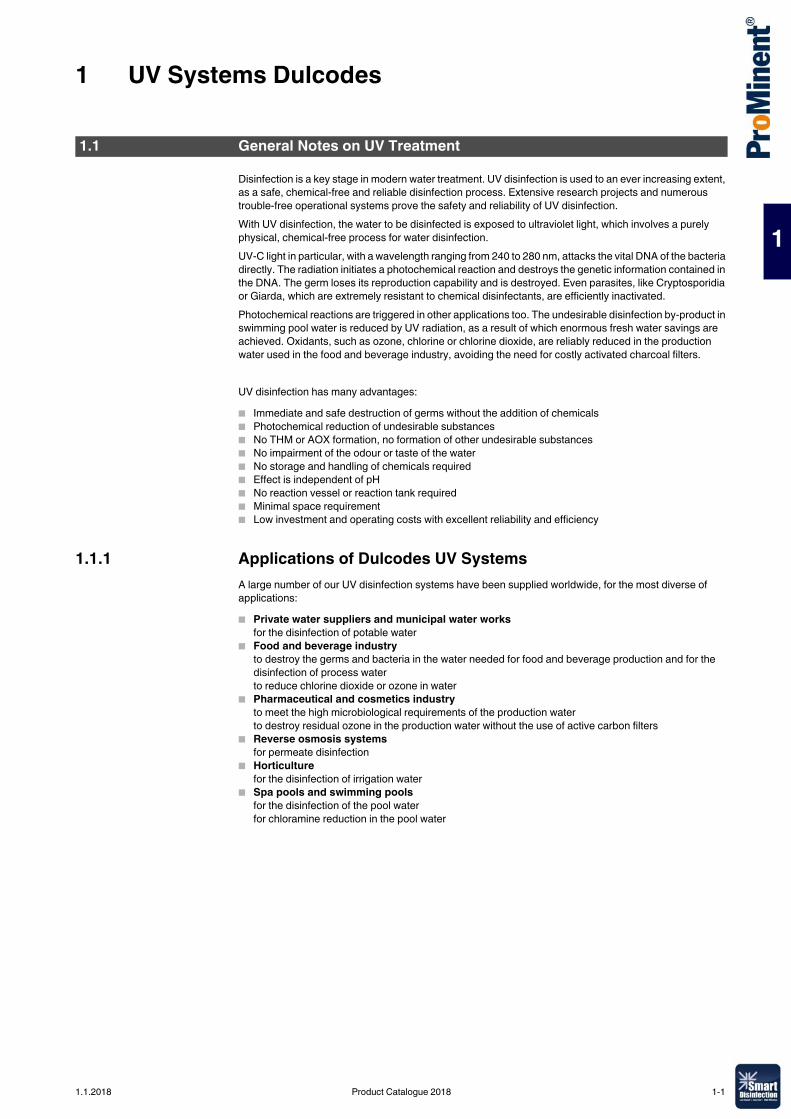
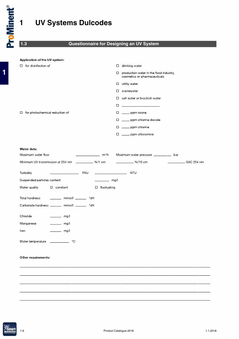
Disinfection is a key stage in modern water treatment. UV disinfection is used to an ever increasing extent, as a safe, chemical-free and reliable disinfection process. Extensive research projects and numerous trouble-free operational systems prove the safety and reliability of UV disinfection.With UV disinfection, the water to be disinfected is exposed to ultraviolet light, which involves a purely physical, chemical-free process for water disinfection.UV-C light in particular, with a wavelength ranging from 240 to 280 nm, attacks the vital DNA of the bacteria directly. The radiation initiates a photochemical reaction and destroys the genetic information contained in the DNA. The germ loses its reproduction capability and is destroyed. Even parasites, like Cryptosporidia or Giarda, which are extremely resistant to chemical disinfectants, are efficiently inactivated.Photochemical reactions are triggered in other applications too. The undesirable disinfection by-product in swimming pool water is reduced by UV radiation, as a result of which enormous fresh water savings are achieved. Oxidants, such as ozone, chlorine or chlorine dioxide, are reliably reduced in the production water used in the food and beverage industry, avoiding the need for costly activated charcoal filters.
UV disinfection has many advantages: � Immediate and safe destruction of germs without the addition of chemicals � Photochemical reduction of undesirable substances� No THM or AOX formation, no formation of other undesirable substances � No impairment of the odour or taste of the water � No storage and handling of chemicals required � Effect is independent of pH� No reaction vessel or reaction tank required� Minimal space requirement � Low investment and operating costs with excellent reliability and efficiency
1.1.1 Applications of Dulcodes UV SystemsA large number of our UV disinfection systems have been supplied worldwide, for the most diverse of applications:� Private water suppliers and municipal water works
for the disinfection of potable water� Food and beverage industry
to destroy the germs and bacteria in the water needed for food and beverage production and for the disinfection of process waterto reduce chlorine dioxide or ozone in water
� Pharmaceutical and cosmetics industryto meet the high microbiological requirements of the production waterto destroy residual ozone in the production water without the use of active carbon filters
� Reverse osmosis systemsfor permeate disinfection
� Horticulturefor the disinfection of irrigation water
� Spa pools and swimming poolsfor the disinfection of the pool waterfor chloramine reduction in the pool water
1.1 General Notes on UV Treatment
1.1.2018 Product Catalogue 2018 1-1
1 UV Systems Dulcodes
1
1.1.2 Description of Dulcodes UV SystemsDulcodes UV disinfection systems essentially consist of:� High-quality reactor made of stainless steel (DIN 1.4404) or UV-resistant plastic� Lamp protection tubes made of high-quality quartz, easily removable for cleaning purposes� Lamps with an exceptionally high UV output in the 254 nm range� Highly selective UV sensors with good long-term and temperature stability� UV system controllers and modern electronic ballasts fitted in a control cabinet
The special features of our Dulcodes UV disinfection systems are: � Uniform UV dose distribution thanks to optimised flow characteristic in the reactor guarantees maximum
flow output with a minimum lamp count and minimum pressure loss� Reduced life cycle costs due to the long life time of high-output lamps with low energy consumption and
high UV output� Unique active temperature management of Vario-flux low-pressure technology adapts the lamp output
in seconds and provides optimum disinfection even with rapidly changing flows and temperature conditions
� Efficient and chemical-free cleaning of the lamp protection tubes with manual or automatic wiper system without interruption to operation
� Continuous monitoring of the reactor temperature by temperature sensor Pt 1000� Electronic ballasts for the soft start and operation and monitoring of individual lamps� Dulcodes LP control cabinet with efficient recirculation cooling ensures the long life of electronic
components and protects against corrosion in aggressive ambient conditions� Various options for simple integration of the unit in higher-level control systems thanks to many
analogue and digital interfaces� User-friendly and intuitive control for the display of operating statuses and adjustment of operating
parameters � Comprehensive biodosimetric validation in line with EPA-UVDGM or DVGW and ÖVGW certification for
selected product ranges confirm disinfection efficiency
Dulcodes UV LampsLow-pressure lamp Vario-FluxNewly developed patented high-output amalgam lamp with a guaranteed expected lamp life of 14,000 operating hours (pro rata). The lamps stand out on account of their high UV output and minimal ageing behaviour. Thanks to the unique combination of electronic ballast technology and the Vario-Flux lamps, they can be controlled quickly and precisely over a broad range of up to 50 % of the nominal power. Seasonal fluctuations of water temperature no longer play a role and are simply compensated for by the active temperature management of the lamp. Efficiency increases even in dimmed mode. This has a particularly positive effect when the actual flow is below the maximum possible flow of the system. The special technology also enables vertical and horizontal installation.
Medium-pressure lamp PowerlineMedium-pressure mercury lamp with a life expectancy of approx. 8,000 to 10,000 operating hours, depending on the lamp size. The high output of these lamps permits the treatment of very large flows. Thanks to their broad range spectrum, these lamps are particularly suitable for photochemical processes. The operating temperature of the lamps is 650 – 850 °C. The water temperature is therefore monitored and the system switches off when a limit temperature is exceeded.
1-2 Product Catalogue 2018 1.1.2018
1 UV Systems Dulcodes
1
Dulcodes UV Controllers Compact controllerCompact unit for the control of all functions of the UV system. The control can be selected for single lamp systems of the Dulcodes LP product range. The display alternately shows the current UV-intensity, the operating hours and the number of lamp activations. The compact controller informs the operator if values fall below freely programmable safety and warning thresholds. Different functions, such as start rinsing, interval rinsing, stagnation rinsing and post-burning time can be freely set on demand.The control has the following inputs and outputs:� Connection for both a rinsing and shut-off valve (230 V)� Potential-free contact output for the end of lamp life, power failure and warning� Potential-free changeover output for operating and collective failure messages� Potential-free contact input for temperature or flow control and pause� 4-20 mA analogue output for sensor signal
Comfort controller UVCbThe Comfort controller consists of a control PCB and a HMI which is integrated in the door of the control cabinet. The control of the UV systems is user-friendly and intuitive. All operating statuses are shown on the display and all operating and fault messages are shown in plain text. The operating status (Operation/Warning/Fault) of the system can be seen from afar by means of LEDs.The Comfort controller UVCb is connected to the ballasts via a bus system so that each individual lamp can be precisely monitored. Different cable lengths are detected automatically and the operating parameters adapted accordingly. The controller, the electronic ballasts and the lamps are perfectly matched to each other. This enables the system to adapt the UVC-output of the low pressure and medium pressure lamp to variable water quality or flow rates via an external 0/4-20 mA signal.Different auxiliary functions, such as the automatic rinsing of the system over a freely programmable rinsing time, the control of a shut-off valve and a circulating pump are integrated as standard. The controller is managing as well the automatic wiper system. During the wiping cycle, the position is multiple controlled for absolute operational safety of the wiper system: by monitoring the end position and by continuous data exchange between the wiper motor and the controller.The UVC sensor signal can be monitored online via an analogue output 0/4-20 mA. Any violation of the warning threshold, minimum radiation intensity and faults are reported via contact outputs. The reactor temperature is monitored by a temperature sensor to avoid overheating.Potential-free inputs make it possible to hook up the UV-system to a higher order control: The "Pause" input can be used to regularly start/stop the system, with the "External fault" input leading to the system being shut down in the event of a fault with an external peripheral component connected. If the application requires different UV doses, a contact input can quickly adapt the UV dose to the changing requirement.The Comfort controller UVCb features data logger. All events are saved on an SD card and can simply be read off on a PC. The UV sensor signal and other measuring parameters, connected to the control via external 0/4-20 mA signals, are stored on the SD card at set time intervals.The control has the following inputs and outputs:� 3 voltage outputs for rinsing and shut-off valve and pump (230 V or 24 V)� 3 potential-free outputs for warning, collective malfunction and operating messages� 4 potential-free inputs for pause, external fault, activate emergency mode, setpoint 1/2 switchover� 1 analogue output 0/4-20 mA for sensor signal� 2 analogue inputs 0/4-20 mA for flow and turbidity or combined chlorine with limit value function� CAN-bus interface for the integration of higher-level controls
Dulcodes A comfort controllerA Siemens S7– 1200 control with a KP 300 Basic operating unit is used for operation and control of Dulcodes A systems. The functionality corresponds to that of the Comfort controller UVCb.
1.1.2018 Product Catalogue 2018 1-3
1 UV Systems Dulcodes
1
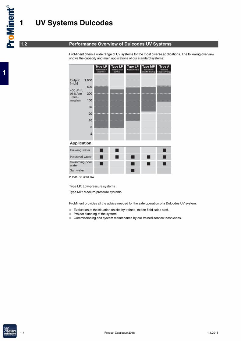
ProMinent offers a wide range of UV systems for the most diverse applications. The following overview shows the capacity and main applications of our standard systems:
P_PMA_DS_0030_SW
Type LP: Low-pressure systemsType MP: Medium-pressure systems
ProMinent provides all the advice needed for the safe operation of a Dulcodes UV system: � Evaluation of the situation on site by trained, expert field sales staff.� Project planning of the system.� Commissioning and system maintenance by our trained service technicians.
1.2 Performance Overview of Dulcodes UV Systems
Type LPPlastic chamber
Type LPStainless steel
certified
Type MP Type AType LPConventional
ballast technologyElectronic
ballast technologyStainless steel
uncertified
1-4 Product Catalogue 2018 1.1.2018
1 UV Systems Dulcodes
1
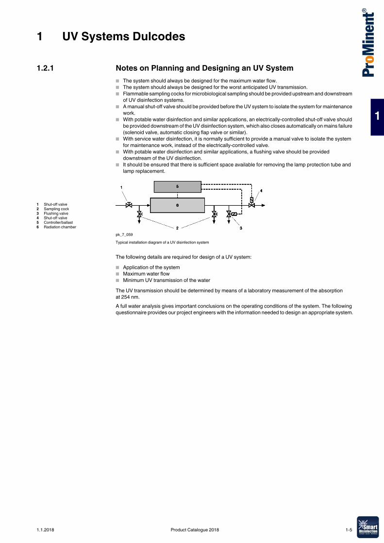
1.2.1 Notes on Planning and Designing an UV System� The system should always be designed for the maximum water flow.� The system should always be designed for the worst anticipated UV transmission.� Flammable sampling cocks for microbiological sampling should be provided upstream and downstream
of UV disinfection systems.� A manual shut-off valve should be provided before the UV system to isolate the system for maintenance
work.� With potable water disinfection and similar applications, an electrically-controlled shut-off valve should
be provided downstream of the UV disinfection system, which also closes automatically on mains failure (solenoid valve, automatic closing flap valve or similar).
� With service water disinfection, it is normally sufficient to provide a manual valve to isolate the system for maintenance work, instead of the electrically-controlled valve.
� With potable water disinfection and similar applications, a flushing valve should be provided downstream of the UV disinfection.
� It should be ensured that there is sufficient space available for removing the lamp protection tube and lamp replacement.
pk_7_059Typical installation diagram of a UV disinfection system
The following details are required for design of a UV system:� Application of the system� Maximum water flow� Minimum UV transmission of the waterThe UV transmission should be determined by means of a laboratory measurement of the absorption at 254 nm.A full water analysis gives important conclusions on the operating conditions of the system. The following questionnaire provides our project engineers with the information needed to design an appropriate system.
1 Shut-off valve2 Sampling cock3 Flushing valve4 Shut-off valve5 Controller/ballast6 Radiation chamber
1.1.2018 Product Catalogue 2018 1-5
1 UV Systems Dulcodes
1
1.3 Questionnaire for Designing an UV System
1-6 Product Catalogue 2018 1.1.2018
1 UV Systems Dulcodes
1
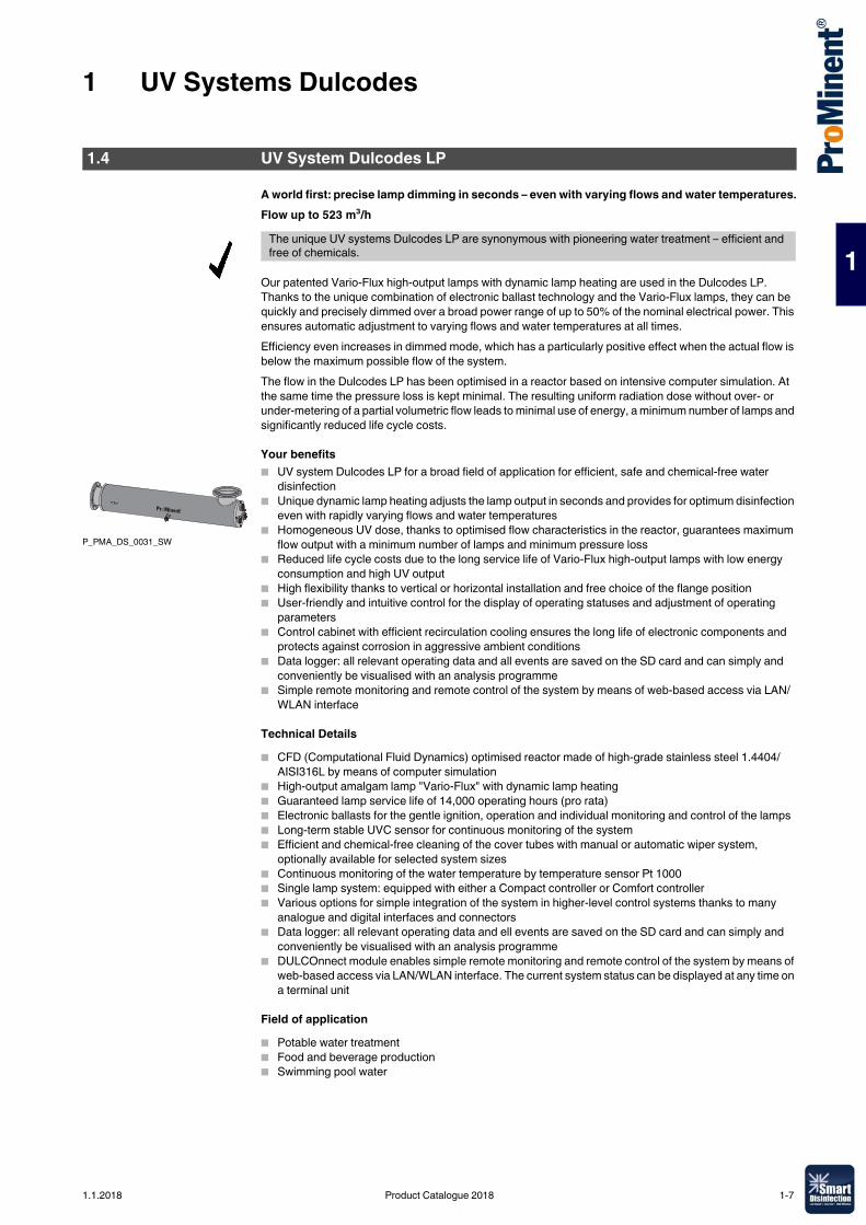
A world first: precise lamp dimming in seconds – even with varying flows and water temperatures.Flow up to 523 m³/h
Our patented Vario-Flux high-output lamps with dynamic lamp heating are used in the Dulcodes LP. Thanks to the unique combination of electronic ballast technology and the Vario-Flux lamps, they can be quickly and precisely dimmed over a broad power range of up to 50% of the nominal electrical power. This ensures automatic adjustment to varying flows and water temperatures at all times.Efficiency even increases in dimmed mode, which has a particularly positive effect when the actual flow is below the maximum possible flow of the system.The flow in the Dulcodes LP has been optimised in a reactor based on intensive computer simulation. At the same time the pressure loss is kept minimal. The resulting uniform radiation dose without over- or under-metering of a partial volumetric flow leads to minimal use of energy, a minimum number of lamps and significantly reduced life cycle costs.
Your benefits� UV system Dulcodes LP for a broad field of application for efficient, safe and chemical-free water
disinfection� Unique dynamic lamp heating adjusts the lamp output in seconds and provides for optimum disinfection
even with rapidly varying flows and water temperatures� Homogeneous UV dose, thanks to optimised flow characteristics in the reactor, guarantees maximum
flow output with a minimum number of lamps and minimum pressure loss� Reduced life cycle costs due to the long service life of Vario-Flux high-output lamps with low energy
consumption and high UV output� High flexibility thanks to vertical or horizontal installation and free choice of the flange position� User-friendly and intuitive control for the display of operating statuses and adjustment of operating
parameters� Control cabinet with efficient recirculation cooling ensures the long life of electronic components and
protects against corrosion in aggressive ambient conditions� Data logger: all relevant operating data and all events are saved on the SD card and can simply and
conveniently be visualised with an analysis programme� Simple remote monitoring and remote control of the system by means of web-based access via LAN/
WLAN interface
Technical Details� CFD (Computational Fluid Dynamics) optimised reactor made of high-grade stainless steel 1.4404/
AISI316L by means of computer simulation� High-output amalgam lamp "Vario-Flux" with dynamic lamp heating� Guaranteed lamp service life of 14,000 operating hours (pro rata)� Electronic ballasts for the gentle ignition, operation and individual monitoring and control of the lamps� Long-term stable UVC sensor for continuous monitoring of the system� Efficient and chemical-free cleaning of the cover tubes with manual or automatic wiper system,
optionally available for selected system sizes� Continuous monitoring of the water temperature by temperature sensor Pt 1000� Single lamp system: equipped with either a Compact controller or Comfort controller� Various options for simple integration of the system in higher-level control systems thanks to many
analogue and digital interfaces and connectors� Data logger: all relevant operating data and ell events are saved on the SD card and can simply and
conveniently be visualised with an analysis programme� DULCOnnect module enables simple remote monitoring and remote control of the system by means of
web-based access via LAN/WLAN interface. The current system status can be displayed at any time on a terminal unit
Field of application� Potable water treatment� Food and beverage production� Swimming pool water
1.4 UV System Dulcodes LP
The unique UV systems Dulcodes LP are synonymous with pioneering water treatment – efficient and free of chemicals.
P_PMA_DS_0031_SW
1.1.2018 Product Catalogue 2018 1-7
1 UV Systems Dulcodes
1
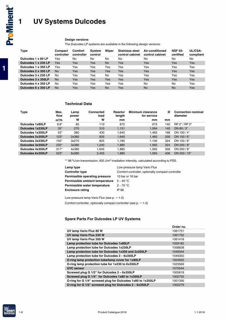
Design versionsThe Dulcodes LP systems are available in the following design versions:
Technical Data
** 98 %/cm transmission; 400 J/m2 irradiation intensity, calculated according to PSS.
Low-pressure lamp Vario Flux (see p. → 1-2)Comfort controller, optionally compact controller (see p. → 1-3)
Spare Parts For Dulcodes LP UV Systems
Type Compact controller
Comfort controller
System control
Wiper Stainless steel control cabinet
Air-conditioned control cabinet
NSF 50-certified
UL/CSA-compliant
Dulcodes 1 x 80 LP Yes No No No No No No NoDulcodes 1 x 230 LP Yes Yes Yes No Yes Yes Yes YesDulcodes 1 x 350 LP Yes Yes Yes Yes Yes Yes Yes YesDulcodes 2 x 350 LP No Yes Yes Yes Yes Yes Yes YesDulcodes 3 x 230 LP No Yes Yes No Yes Yes Yes YesDulcodes 3 x 350LP No Yes Yes Yes Yes Yes Yes YesDulcodes 4 x 350 LP No Yes Yes Yes Yes No No YesDulcodes 6 x 350 LP No Yes Yes No Yes No No Yes
Type Max.flow
Lamppower
Connectedload
Reactorlength
Minimum clearancefor service
Ø Connection nominal diameter
m3/h W W mm mm mmDulcodes 1x80LP 8.8* 85 110 872 973 140 RP 2" / RP 2"Dulcodes 1x230LP 35* 270 310 1,151 1,064 140 DN 80 / 3"Dulcodes 1x350LP 53* 380 430 1,640 1,465 168 DN 100 / 4"Dulcodes 2x350LP 123* 2x380 835 1,640 1,465 256 DN 150 / 6"Dulcodes 3x230LP 155* 3x270 825 1,185 1,156 324 DN 150 / 6"Dulcodes 3x350LP 232* 3x380 1,240 1,885 1,565 324 DN 200 / 8"Dulcodes 4x350LP 317* 4x380 1,645 1,885 1,565 356 DN 200 / 8"Dulcodes 6x350LP 523* 6x380 2,455 1,885 1,565 406 DN 250 / 10"
Lamp type Low-pressure lamp Vario FluxController type Comfort controller, optionally compact controllerPermissible operating pressure 10 bar or 16 barPermissible ambient temperature 5 – 40 °CPermissible water temperature 2 – 70 °CEnclosure rating IP 66
Order no.UV lamp Vario Flux 80 W 1061751UV lamp Vario Flux 230 W 1061752UV lamp Vario Flux 350 W 1061418Lamp protection tube for Dulcodes 1x80LP 1059182Lamp protection tube for Dulcodes 1x230LP 1058838Lamp protection tube for Dulcodes 1x350 and 2x350LP 1049344Lamp protection tube for Dulcodes 3 – 6x350LP 1049350O-ring lamp protection tube/lamp cover for 1x80LP 1004920O-ring lamp protection tube for 1x230 to 6x350LP 1023569UVC sensor 1075544Screwed plug G 1/2" for Dulcodes 2 – 6x350LP 1005818Screwed plug G 1/4" for Dulcodes 1x80 to 1x350LP 1002752O-ring for G 1/4" screwed plug for Dulcodes 1x80 to 1x350LP 1001356O-ring for G 1/2" screwed plug for Dulcodes 2 – 6x350LP 1002279
1-8 Product Catalogue 2018 1.1.2018
1 UV Systems Dulcodes
1
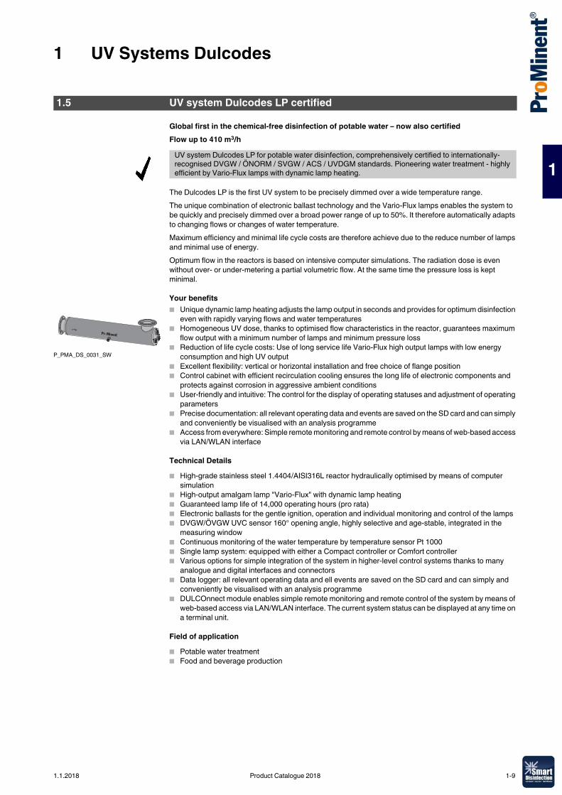
Global first in the chemical-free disinfection of potable water – now also certifiedFlow up to 410 m3/h
The Dulcodes LP is the first UV system to be precisely dimmed over a wide temperature range.The unique combination of electronic ballast technology and the Vario-Flux lamps enables the system to be quickly and precisely dimmed over a broad power range of up to 50%. It therefore automatically adapts to changing flows or changes of water temperature.Maximum efficiency and minimal life cycle costs are therefore achieve due to the reduce number of lamps and minimal use of energy.Optimum flow in the reactors is based on intensive computer simulations. The radiation dose is even without over- or under-metering a partial volumetric flow. At the same time the pressure loss is kept minimal.
Your benefits� Unique dynamic lamp heating adjusts the lamp output in seconds and provides for optimum disinfection
even with rapidly varying flows and water temperatures� Homogeneous UV dose, thanks to optimised flow characteristics in the reactor, guarantees maximum
flow output with a minimum number of lamps and minimum pressure loss� Reduction of life cycle costs: Use of long service life Vario-Flux high output lamps with low energy
consumption and high UV output� Excellent flexibility: vertical or horizontal installation and free choice of flange position� Control cabinet with efficient recirculation cooling ensures the long life of electronic components and
protects against corrosion in aggressive ambient conditions� User-friendly and intuitive: The control for the display of operating statuses and adjustment of operating
parameters� Precise documentation: all relevant operating data and events are saved on the SD card and can simply
and conveniently be visualised with an analysis programme� Access from everywhere: Simple remote monitoring and remote control by means of web-based access
via LAN/WLAN interface
Technical Details� High-grade stainless steel 1.4404/AISI316L reactor hydraulically optimised by means of computer
simulation� High-output amalgam lamp "Vario-Flux" with dynamic lamp heating� Guaranteed lamp life of 14,000 operating hours (pro rata)� Electronic ballasts for the gentle ignition, operation and individual monitoring and control of the lamps� DVGW/ÖVGW UVC sensor 160° opening angle, highly selective and age-stable, integrated in the
measuring window� Continuous monitoring of the water temperature by temperature sensor Pt 1000� Single lamp system: equipped with either a Compact controller or Comfort controller� Various options for simple integration of the system in higher-level control systems thanks to many
analogue and digital interfaces and connectors� Data logger: all relevant operating data and ell events are saved on the SD card and can simply and
conveniently be visualised with an analysis programme� DULCOnnect module enables simple remote monitoring and remote control of the system by means of
web-based access via LAN/WLAN interface. The current system status can be displayed at any time on a terminal unit.
Field of application� Potable water treatment� Food and beverage production
1.5 UV system Dulcodes LP certified
UV system Dulcodes LP for potable water disinfection, comprehensively certified to internationally-recognised DVGW / ÖNORM / SVGW / ACS / UVDGM standards. Pioneering water treatment - highly efficient by Vario-Flux lamps with dynamic lamp heating.
P_PMA_DS_0031_SW
1.1.2018 Product Catalogue 2018 1-9
1 UV Systems Dulcodes
1
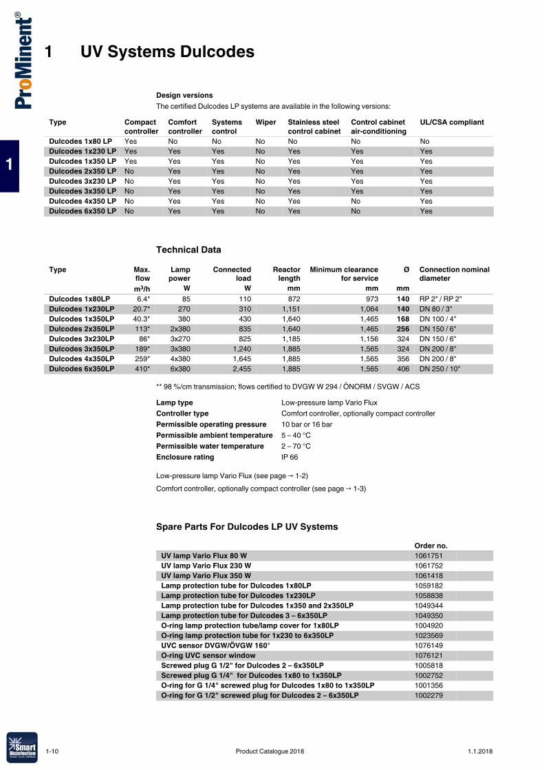
Design versionsThe certified Dulcodes LP systems are available in the following versions:
Technical Data
** 98 %/cm transmission; flows certified to DVGW W 294 / ÖNORM / SVGW / ACS
Low-pressure lamp Vario Flux (see page → 1-2)Comfort controller, optionally compact controller (see page → 1-3)
Spare Parts For Dulcodes LP UV Systems
Type Compact controller
Comfort controller
Systems control
Wiper Stainless steel control cabinet
Control cabinet air-conditioning
UL/CSA compliant
Dulcodes 1x80 LP Yes No No No No No NoDulcodes 1x230 LP Yes Yes Yes No Yes Yes YesDulcodes 1x350 LP Yes Yes Yes No Yes Yes YesDulcodes 2x350 LP No Yes Yes No Yes Yes YesDulcodes 3x230 LP No Yes Yes No Yes Yes YesDulcodes 3x350 LP No Yes Yes No Yes Yes YesDulcodes 4x350 LP No Yes Yes No Yes No YesDulcodes 6x350 LP No Yes Yes No Yes No Yes
Type Max.flow
Lamppower
Connectedload
Reactorlength
Minimum clearancefor service
Ø Connection nominal diameter
m3/h W W mm mm mmDulcodes 1x80LP 6.4* 85 110 872 973 140 RP 2" / RP 2"Dulcodes 1x230LP 20.7* 270 310 1,151 1,064 140 DN 80 / 3"Dulcodes 1x350LP 40.3* 380 430 1,640 1,465 168 DN 100 / 4"Dulcodes 2x350LP 113* 2x380 835 1,640 1,465 256 DN 150 / 6"Dulcodes 3x230LP 86* 3x270 825 1,185 1,156 324 DN 150 / 6"Dulcodes 3x350LP 189* 3x380 1,240 1,885 1,565 324 DN 200 / 8"Dulcodes 4x350LP 259* 4x380 1,645 1,885 1,565 356 DN 200 / 8"Dulcodes 6x350LP 410* 6x380 2,455 1,885 1,565 406 DN 250 / 10"
Lamp type Low-pressure lamp Vario FluxController type Comfort controller, optionally compact controllerPermissible operating pressure 10 bar or 16 barPermissible ambient temperature 5 – 40 °CPermissible water temperature 2 – 70 °CEnclosure rating IP 66
Order no.UV lamp Vario Flux 80 W 1061751UV lamp Vario Flux 230 W 1061752UV lamp Vario Flux 350 W 1061418Lamp protection tube for Dulcodes 1x80LP 1059182Lamp protection tube for Dulcodes 1x230LP 1058838Lamp protection tube for Dulcodes 1x350 and 2x350LP 1049344Lamp protection tube for Dulcodes 3 – 6x350LP 1049350O-ring lamp protection tube/lamp cover for 1x80LP 1004920O-ring lamp protection tube for 1x230 to 6x350LP 1023569UVC sensor DVGW/ÖVGW 160° 1076149O-ring UVC sensor window 1076121Screwed plug G 1/2" for Dulcodes 2 – 6x350LP 1005818Screwed plug G 1/4" for Dulcodes 1x80 to 1x350LP 1002752O-ring for G 1/4" screwed plug for Dulcodes 1x80 to 1x350LP 1001356O-ring for G 1/2" screwed plug for Dulcodes 2 – 6x350LP 1002279
1-10 Product Catalogue 2018 1.1.2018
1 UV Systems Dulcodes
1
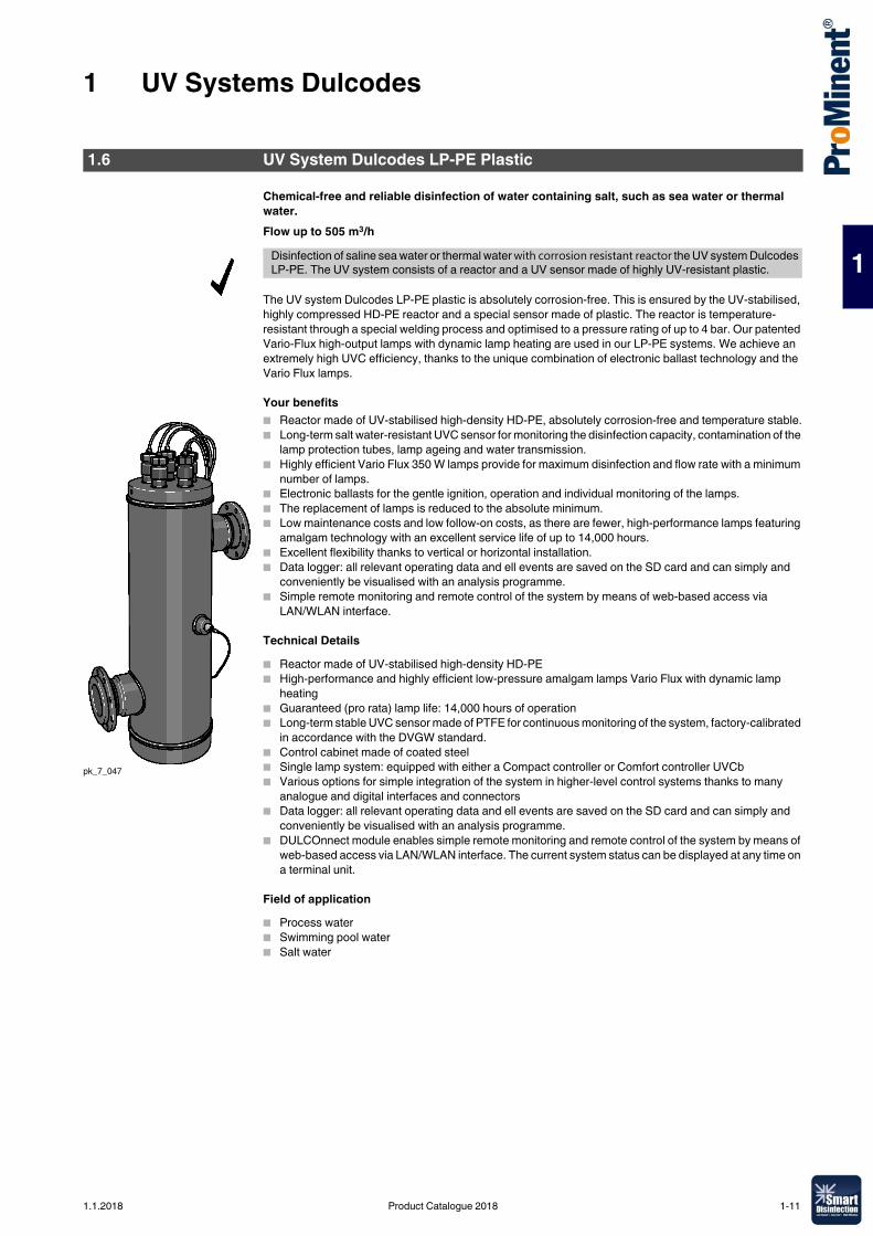
Chemical-free and reliable disinfection of water containing salt, such as sea water or thermal water.Flow up to 505 m3/h
The UV system Dulcodes LP-PE plastic is absolutely corrosion-free. This is ensured by the UV-stabilised, highly compressed HD-PE reactor and a special sensor made of plastic. The reactor is temperature-resistant through a special welding process and optimised to a pressure rating of up to 4 bar. Our patented Vario-Flux high-output lamps with dynamic lamp heating are used in our LP-PE systems. We achieve an extremely high UVC efficiency, thanks to the unique combination of electronic ballast technology and the Vario Flux lamps.
Your benefits� Reactor made of UV-stabilised high-density HD-PE, absolutely corrosion-free and temperature stable.� Long-term salt water-resistant UVC sensor for monitoring the disinfection capacity, contamination of the
lamp protection tubes, lamp ageing and water transmission. � Highly efficient Vario Flux 350 W lamps provide for maximum disinfection and flow rate with a minimum
number of lamps.� Electronic ballasts for the gentle ignition, operation and individual monitoring of the lamps.� The replacement of lamps is reduced to the absolute minimum.� Low maintenance costs and low follow-on costs, as there are fewer, high-performance lamps featuring
amalgam technology with an excellent service life of up to 14,000 hours.� Excellent flexibility thanks to vertical or horizontal installation.� Data logger: all relevant operating data and ell events are saved on the SD card and can simply and
conveniently be visualised with an analysis programme.� Simple remote monitoring and remote control of the system by means of web-based access via
LAN/WLAN interface.
Technical Details� Reactor made of UV-stabilised high-density HD-PE� High-performance and highly efficient low-pressure amalgam lamps Vario Flux with dynamic lamp
heating� Guaranteed (pro rata) lamp life: 14,000 hours of operation� Long-term stable UVC sensor made of PTFE for continuous monitoring of the system, factory-calibrated
in accordance with the DVGW standard. � Control cabinet made of coated steel� Single lamp system: equipped with either a Compact controller or Comfort controller UVCb� Various options for simple integration of the system in higher-level control systems thanks to many
analogue and digital interfaces and connectors� Data logger: all relevant operating data and ell events are saved on the SD card and can simply and
conveniently be visualised with an analysis programme.� DULCOnnect module enables simple remote monitoring and remote control of the system by means of
web-based access via LAN/WLAN interface. The current system status can be displayed at any time on a terminal unit.
Field of application� Process water� Swimming pool water� Salt water
1.6 UV System Dulcodes LP-PE Plastic
Disinfection of saline sea water or thermal water with corrosion resistant reactor the UV system Dulcodes LP-PE. The UV system consists of a reactor and a UV sensor made of highly UV-resistant plastic.
pk_7_047
1.1.2018 Product Catalogue 2018 1-11
1 UV Systems Dulcodes
1
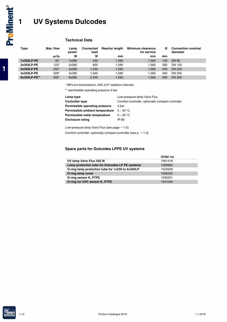
Technical Data
* 98%/cm transmission; 400 J/m2 radiation intensity** permissible operating pressure 3 bar
Low-pressure lamp Vario Flux (see page → 1-2)Comfort controller, optionally compact controller (see p. → 1-3)
Spare parts for Dulcodes LPPE UV systems
Type Max. flow Lamppower
Connectedload
Reactor length Minimum clearancefor service
Ø Connection nominal diameter
m3/h W W mm mm mm1x350LP-PE 35* 1x380 430 1,590 1,565 140 DN 802x350LP-PE 123* 2x380 835 1,590 1,565 280 DN 1253x350LP-PE 252* 3x380 1,240 1,590 1,565 400 DN 2004x350LP-PE 328* 4x380 1,645 1,590 1,565 400 DN 2006x350LP-PE** 505* 6x380 2,455 1,590 1,565 500 DN 300
Lamp type Low-pressure lamp Vario FluxController type Comfort controller, optionally compact controllerPermissible operating pressure 4 barPermissible ambient temperature 5 – 40 °CPermissible water temperature 5 – 30 °CEnclosure rating IP 66
Order no.UV lamp Vario Flux 350 W 1061418Lamp protection tube for Dulcodes LP PE systems 1026694O-ring lamp protection tube for 1x230 to 6x350LP 1023569O-ring lamp cover 1006332O-ring sensor K, PTFE 1035201O-ring for UVC sensor K, PTFE 1041049
1-12 Product Catalogue 2018 1.1.2018
1 UV Systems Dulcodes
1
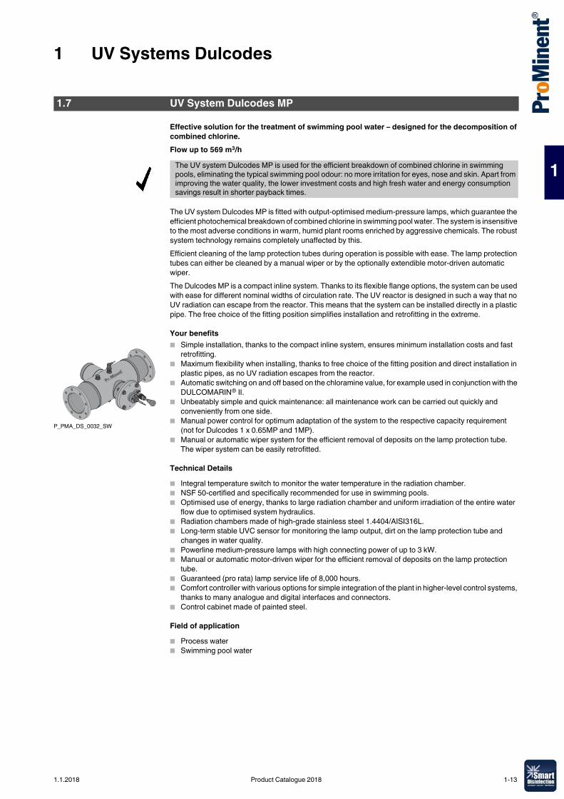
Effective solution for the treatment of swimming pool water – designed for the decomposition of combined chlorine.Flow up to 569 m3/h
The UV system Dulcodes MP is fitted with output-optimised medium-pressure lamps, which guarantee the efficient photochemical breakdown of combined chlorine in swimming pool water. The system is insensitive to the most adverse conditions in warm, humid plant rooms enriched by aggressive chemicals. The robust system technology remains completely unaffected by this.Efficient cleaning of the lamp protection tubes during operation is possible with ease. The lamp protection tubes can either be cleaned by a manual wiper or by the optionally extendible motor-driven automatic wiper.The Dulcodes MP is a compact inline system. Thanks to its flexible flange options, the system can be used with ease for different nominal widths of circulation rate. The UV reactor is designed in such a way that no UV radiation can escape from the reactor. This means that the system can be installed directly in a plastic pipe. The free choice of the fitting position simplifies installation and retrofitting in the extreme.
Your benefits� Simple installation, thanks to the compact inline system, ensures minimum installation costs and fast
retrofitting.� Maximum flexibility when installing, thanks to free choice of the fitting position and direct installation in
plastic pipes, as no UV radiation escapes from the reactor.� Automatic switching on and off based on the chloramine value, for example used in conjunction with the
DULCOMARIN® II. � Unbeatably simple and quick maintenance: all maintenance work can be carried out quickly and
conveniently from one side.� Manual power control for optimum adaptation of the system to the respective capacity requirement
(not for Dulcodes 1 x 0.65MP and 1MP).� Manual or automatic wiper system for the efficient removal of deposits on the lamp protection tube.
The wiper system can be easily retrofitted.
Technical Details� Integral temperature switch to monitor the water temperature in the radiation chamber.� NSF 50-certified and specifically recommended for use in swimming pools.� Optimised use of energy, thanks to large radiation chamber and uniform irradiation of the entire water
flow due to optimised system hydraulics.� Radiation chambers made of high-grade stainless steel 1.4404/AISI316L.� Long-term stable UVC sensor for monitoring the lamp output, dirt on the lamp protection tube and
changes in water quality.� Powerline medium-pressure lamps with high connecting power of up to 3 kW.� Manual or automatic motor-driven wiper for the efficient removal of deposits on the lamp protection
tube.� Guaranteed (pro rata) lamp service life of 8,000 hours.� Comfort controller with various options for simple integration of the plant in higher-level control systems,
thanks to many analogue and digital interfaces and connectors.� Control cabinet made of painted steel.
Field of application� Process water� Swimming pool water
1.7 UV System Dulcodes MP
The UV system Dulcodes MP is used for the efficient breakdown of combined chlorine in swimming pools, eliminating the typical swimming pool odour: no more irritation for eyes, nose and skin. Apart from improving the water quality, the lower investment costs and high fresh water and energy consumption savings result in shorter payback times.
P_PMA_DS_0032_SW
1.1.2018 Product Catalogue 2018 1-13
1 UV Systems Dulcodes
1
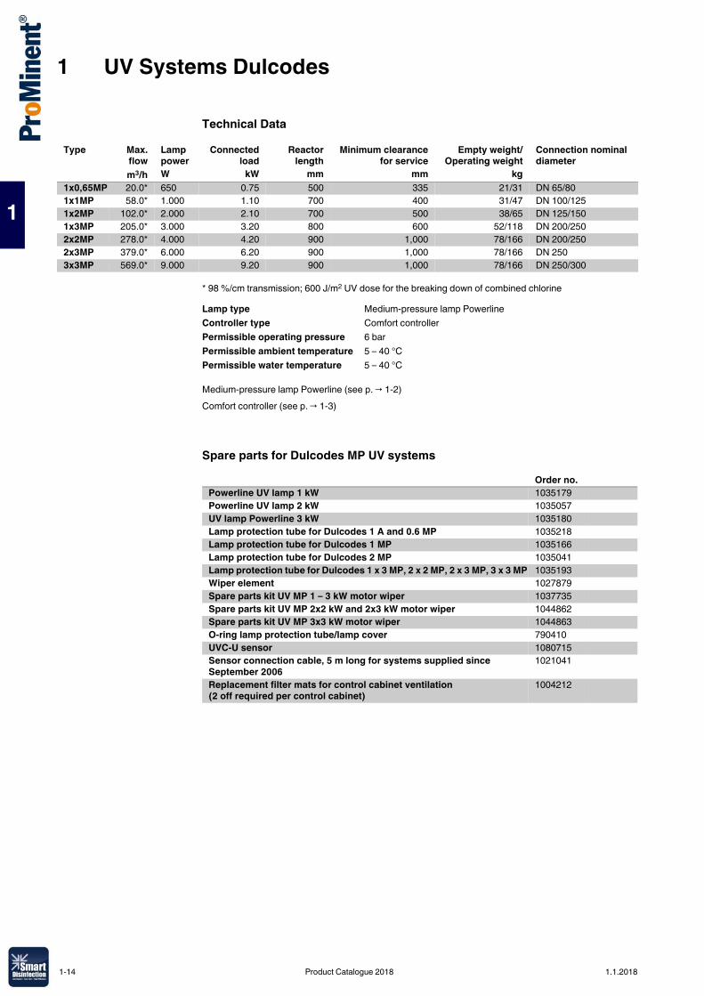
Technical Data
* 98 %/cm transmission; 600 J/m2 UV dose for the breaking down of combined chlorine
Medium-pressure lamp Powerline (see p. → 1-2)Comfort controller (see p. → 1-3)
Spare parts for Dulcodes MP UV systems
Type Max.flow
Lamp power
Connectedload
Reactorlength
Minimum clearancefor service
Empty weight/Operating weight
Connection nominal diameter
m3/h W kW mm mm kg1x0,65MP 20.0* 650 0.75 500 335 21/31 DN 65/801x1MP 58.0* 1.000 1.10 700 400 31/47 DN 100/1251x2MP 102.0* 2.000 2.10 700 500 38/65 DN 125/1501x3MP 205.0* 3.000 3.20 800 600 52/118 DN 200/2502x2MP 278.0* 4.000 4.20 900 1,000 78/166 DN 200/2502x3MP 379.0* 6.000 6.20 900 1,000 78/166 DN 2503x3MP 569.0* 9.000 9.20 900 1,000 78/166 DN 250/300
Lamp type Medium-pressure lamp PowerlineController type Comfort controllerPermissible operating pressure 6 barPermissible ambient temperature 5 – 40 °CPermissible water temperature 5 – 40 °C
Order no.Powerline UV lamp 1 kW 1035179Powerline UV lamp 2 kW 1035057UV lamp Powerline 3 kW 1035180Lamp protection tube for Dulcodes 1 A and 0.6 MP 1035218Lamp protection tube for Dulcodes 1 MP 1035166Lamp protection tube for Dulcodes 2 MP 1035041Lamp protection tube for Dulcodes 1 x 3 MP, 2 x 2 MP, 2 x 3 MP, 3 x 3 MP 1035193Wiper element 1027879Spare parts kit UV MP 1 – 3 kW motor wiper 1037735Spare parts kit UV MP 2x2 kW and 2x3 kW motor wiper 1044862Spare parts kit UV MP 3x3 kW motor wiper 1044863O-ring lamp protection tube/lamp cover 790410UVC-U sensor 1080715Sensor connection cable, 5 m long for systems supplied since September 2006
1021041
Replacement filter mats for control cabinet ventilation (2 off required per control cabinet)
1004212
1-14 Product Catalogue 2018 1.1.2018
1 UV Systems Dulcodes
1
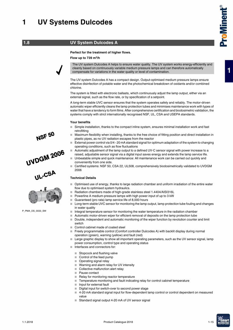
Perfect for the treatment of higher flows.Flow up to 739 m3/h
The UV system Dulcodes A has a compact design. Output-optimised medium pressure lamps ensure effective disinfection of potable water and the photochemical breakdown of oxidants and/or combined chlorine.The system is fitted with electronic ballasts, which continuously adjust the lamp output, either via an external signal, such as the flow rate, or by specification of a setpoint.A long-term stable UVC sensor ensures that the system operates safely and reliably. The motor-driven automatic wiper efficiently cleans the lamp protection tubes and minimises maintenance work with types of water that have a tendency to form films. After comprehensive certification and biodosimetric validation, the systems comply with strict internationally recognised NSF, UL, CSA and USEPA standards.
Your benefits� Simple installation, thanks to the compact inline system, ensures minimal installation work and fast
retrofitting� Maximum flexibility when installing, thanks to the free choice of fitting position and direct installation in
plastic pipes, as no UV radiation escapes from the reactor� External power control via 0/4 - 20 mA standard signal for optimum adaptation of the system to changing
operating conditions, such as flow fluctuations � Automatic adjustment of the lamp output to a defined UV-C sensor signal with power increase to a
raised, adjustable sensor signal via a digital input saves energy and extends the lamp service life.� Unbeatable simple and quick maintenance: All maintenance work can be carried out quickly and
conveniently from one side.� Certified systems: NSF 50, CSA 22, UL508, comprehensively biodosimetrically validated to UVDGM
2006
Technical Details� Optimised use of energy, thanks to large radiation chamber and uniform irradiation of the entire water
flow due to optimised system hydraulics.� Radiation chambers made of high-grade stainless steel 1.4404/AISI316L� Powerline A medium-pressure lamps with high power input of up to 3 kW� Guaranteed (pro rata) lamp service life of 8,000 hours� Long-term stable UVC sensor for monitoring the lamp output, lamp protection tube fouling and changes
in water quality� Integral temperature sensor for monitoring the water temperature in the radiation chamber� Automatic motor-driven wiper for efficient removal of deposits on the lamp protection tube� Double, independent and automatic monitoring of the wiper function by revolution counter and limit
switch� Control cabinet made of coated steel� Freely programmable control (Comfort controller Dulcodes A) with backlit display during normal
operation (green), warning (yellow) and fault (red)� Large graphic display to show all important operating parameters, such as the UV sensor signal, lamp
power consumption, control type and operating status � Interfaces and connectors for:
� Stopcock and flushing valve� Control of the feed pump� Operating signal relay� Warning and alarm relay for UV intensity� Collective malfunction alert relay� Pause contact� Relay for monitoring reactor temperature� Temperature monitoring and fault indicating relay for control cabinet temperature� Input for external fault� Digital input for switch-over to second power stage� 4-20 mA standard signal input for flow-dependent lamp control or control dependent on measured
value� Standard signal output 4-20 mA of UV sensor signal
1.8 UV System Dulcodes A
The UV system Dulcodes A helps to ensure water quality. The UV system works energy-efficiently and cleanly based on continuously variable medium pressure lamps and can therefore automatically compensate for variations in the water quality or level of contamination.
P_PMA_DS_0033_SW
1.1.2018 Product Catalogue 2018 1-15
1 UV Systems Dulcodes
1
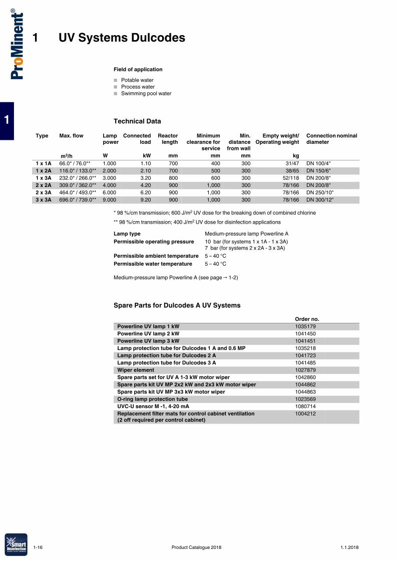
Field of application� Potable water� Process water� Swimming pool water
Technical Data
* 98 %/cm transmission; 600 J/m2 UV dose for the breaking down of combined chlorine** 98 %/cm transmission; 400 J/m2 UV dose for disinfection applications
Medium-pressure lamp Powerline A (see page → 1-2)
Spare Parts for Dulcodes A UV Systems
Type Max. flow Lamp power
Connectedload
Reactorlength
Minimumclearance for
service
Min.distance
from wall
Empty weight/Operating weight
Connection nominal diameter
m3/h W kW mm mm mm kg1 x 1A 66.0* / 76.0** 1.000 1.10 700 400 300 31/47 DN 100/4"1 x 2A 116.0* / 133.0** 2.000 2.10 700 500 300 38/65 DN 150/6"1 x 3A 232.0* / 266.0** 3.000 3.20 800 600 300 52/118 DN 200/8"2 x 2A 309.0* / 362.0** 4.000 4.20 900 1,000 300 78/166 DN 200/8"2 x 3A 464.0* / 493.0** 6.000 6.20 900 1,000 300 78/166 DN 250/10"3 x 3A 696.0* / 739.0** 9.000 9.20 900 1,000 300 78/166 DN 300/12"
Lamp type Medium-pressure lamp Powerline APermissible operating pressure 10 bar (for systems 1 x 1A - 1 x 3A)
7 bar (for systems 2 x 2A - 3 x 3A)Permissible ambient temperature 5 – 40 °CPermissible water temperature 5 – 40 °C
Order no.Powerline UV lamp 1 kW 1035179Powerline UV lamp 2 kW 1041450Powerline UV lamp 3 kW 1041451Lamp protection tube for Dulcodes 1 A and 0.6 MP 1035218Lamp protection tube for Dulcodes 2 A 1041723Lamp protection tube for Dulcodes 3 A 1041485Wiper element 1027879Spare parts set for UV A 1-3 kW motor wiper 1042860Spare parts kit UV MP 2x2 kW and 2x3 kW motor wiper 1044862Spare parts kit UV MP 3x3 kW motor wiper 1044863O-ring lamp protection tube 1023569UVC-U sensor M -1, 4-20 mA 1080714Replacement filter mats for control cabinet ventilation (2 off required per control cabinet)
1004212
1-16 Product Catalogue 2018 1.1.2018
1 UV Systems Dulcodes
1
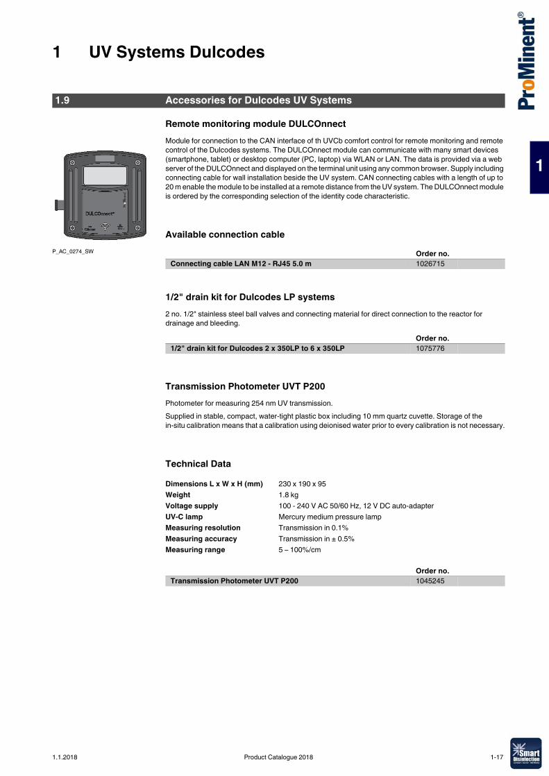
Remote monitoring module DULCOnnectModule for connection to the CAN interface of th UVCb comfort control for remote monitoring and remote control of the Dulcodes systems. The DULCOnnect module can communicate with many smart devices (smartphone, tablet) or desktop computer (PC, laptop) via WLAN or LAN. The data is provided via a web server of the DULCOnnect and displayed on the terminal unit using any common browser. Supply including connecting cable for wall installation beside the UV system. CAN connecting cables with a length of up to 20 m enable the module to be installed at a remote distance from the UV system. The DULCOnnect module is ordered by the corresponding selection of the identity code characteristic.
Available connection cable
1/2" drain kit for Dulcodes LP systems2 no. 1/2" stainless steel ball valves and connecting material for direct connection to the reactor for drainage and bleeding.
Transmission Photometer UVT P200Photometer for measuring 254 nm UV transmission.Supplied in stable, compact, water-tight plastic box including 10 mm quartz cuvette. Storage of the in-situ calibration means that a calibration using deionised water prior to every calibration is not necessary.
Technical Data
1.9 Accessories for Dulcodes UV Systems
P_AC_0274_SW Order no.Connecting cable LAN M12 - RJ45 5.0 m 1026715
Order no.1/2" drain kit for Dulcodes 2 x 350LP to 6 x 350LP 1075776
Dimensions L x W x H (mm) 230 x 190 x 95Weight 1.8 kgVoltage supply 100 - 240 V AC 50/60 Hz, 12 V DC auto-adapterUV-C lamp Mercury medium pressure lampMeasuring resolution Transmission in 0.1%Measuring accuracy Transmission in ± 0.5%Measuring range 5 – 100%/cm
Order no.Transmission Photometer UVT P200 1045245
1.1.2018 Product Catalogue 2018 1-17
1 UV Systems Dulcodes
1
Reference Radiometer RRMReference radiometer for checking certified UV systems Dulcodes LP. The portable instrument is fitted with an insertion sensor which is used for measurement of the radiation intensity without operational interruption directly in the radiation chamber of the Dulcodes LP in place of the unit sensor. Suitable UV protective glasses should be worn as UV radiation escapes from the radiation chamber during this procedure.
Technical Data
UV Protective GlassesProtective glasses to protect against UV radiation that can be harmful to the eyes when working on open UV systems.
Protective GlovesProtective gloves made of white cotton to avoid fingerprints on UV lamps and lamp sleeves. 1 pair universal size.
Sampling CockFireproof sampling cock made of stainless steel.
Cleaning SystemCleaning system for flushing the radiation chamber with a cleaning solution to remove deposits on the lamp tubes and internal surfaces of the UV system. Consists of chemical tanks, booster and metering pumps, valves and complete automatic or manual controller. Design and technical equipment are matched to the particular UV system and its application.
Measuring range 20/200/2,000/20,000 W/m² (switchable)Display 3-digitVoltage supply Battery, 9 V Type 6F22 or equivalent
Order no.Reference radiometer RRM for measuring field angle 40° 1025094Reference radiometer RRM for measuring field angle 160° 1076575Reference radiometer RRM for measuring field angle 40° and 160° 1076576
Order no.UV protective glasses 1025243
Order no.Protective gloves 1032815
Order no.Sampling cock On request
Order no.Cleaning system On request
1-18 Product Catalogue 2018 1.1.2018
1 UV Systems Dulcodes
1
FittingsFittings provided for quick and easy wall mounting of the UV radiation chamber. Fitting parts comprise 2 screw-in pipe clips in high alloy steel (V2A), 2 base plates with M12 nut, 2 set screws and 4 M12 hexagon nuts.Two-part clip with increased material cross-section to ensure high bearing strength and breaking resistance. A soundproofing layer ensures marked resistance in the sound level.
Overvoltage ProtectionOvervoltage protection for Dulcodes UV systems operated at 230 V 50-60 Hz.The external overvoltage protection is intended for operations when the device´s internal protection is not sufficient for surge voltages of 1 kV between the conductors and 2 kV to earth. An overvoltage trip can be fitted as a low protection surge arrestor to significantly increase the stability of the Dulcodes systems to protect them when the supply mains is prone to disturbance energy.It can only be determined by thorough investigation of the voltage behaviour on site whether the low protection surge arrester requires further measures, such as medium and main protection.
Replacement Plug-in Insert After Tripping
Clip-on thermostat for systems with compact control
Type Order no.Fittings A2 1x80LP, 1x230LP 1039828
1x350LP, 3x230LP 10778232x350LP 1077844
Order no.Fine protection PT 2-DE IS 230 IAC 733010
Order no.Replacement plug-in insert PT 2-DE / S 230 / AC - ST 733011
Order no.Clip-on thermostat 30-90 °C 230 VAC 104394
1.1.2018 Product Catalogue 2018 1-19

1-20 Product Catalogue 2018 1.1.2018
2 Ozone Systems OZONFILT®
2
2.0.1Product Catalogue 2018
As the most powerful oxidant that can be used in water treatment, ozone permits a broad spectrum of possible applications:
Outstanding disinfection action against� Bacteria and viruses � Fungi and parasites
Oxidation of undesirable inorganic substances in the water� Iron and manganese� Arsenic� Nitrite and sulphide
Oxidation of undesirable organic substances in the water� Strong-smelling and strong-tasting compounds� Humic substances and other compounds which affect the colour of the water� Cyclic hydrocarbons� Trihalomethanes, chloramines and other chlorine compounds
Micro-flocculating properties
� After oxidation with ozone, substances and colloids dissolved in the water become insoluble and can be filtered
Significantly less environmentally harmful by-products result from the generation and use of ozone than other comparable oxidants and disinfectants. As a highly reactive gas, ozone is generated on site from oxygen, and introduced to the water directly, without interim storage. Because of its high reactivity, ozone decomposes into oxygen again in the water, with a half-life of several minutes. Therefore all components of an ozone handling system have to be perfectly coordinated to each other and the planned application, to achieve an optimum relationship between ozone generation and its effect.With every new project, our engineers draw on experience that we have accumulated since 1971 in the following applications:
Potable water supply� Oxidation of iron, manganese or arsenic� Refinement and improvement of taste� Disinfection
Food and beverage industry� Disinfection of table water� Disinfection of rinsers in the beverage industry� Disinfection of process water
Swimming pools� Reduction of chloramines and trihalomethanes, avoiding typical swimming pool odours� Crystal clear water, thanks to micro-flocculating action� Reliable microbiological barriers in therapy pools� Reduction of investment and operating costs by the possibility of reducing the circulating power and
throttling the fresh water inlet
Industry� Cooling water treatment� Combating legionella in cooling water circuits� Disinfection of process water� Removal of odorous substances in air scrubbers
Municipal waste water treatment� Breakdown of trace substances� Reduction of clarifier sludge� COD reduction/breakdown � Removal of colouring
2.1 Ozone In Water Treatment
1.1.2018 Product Catalogue 2018 2-1
2 Ozone Systems OZONFILT®
2
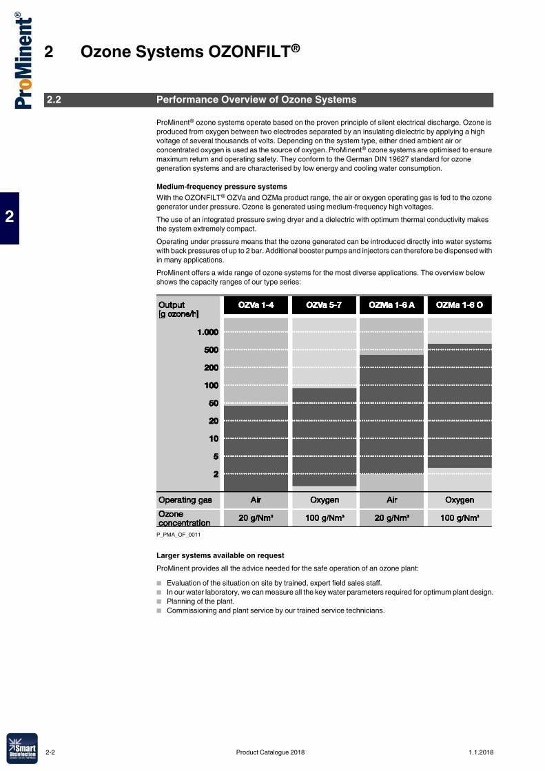
ProMinent® ozone systems operate based on the proven principle of silent electrical discharge. Ozone is produced from oxygen between two electrodes separated by an insulating dielectric by applying a high voltage of several thousands of volts. Depending on the system type, either dried ambient air or concentrated oxygen is used as the source of oxygen. ProMinent® ozone systems are optimised to ensure maximum return and operating safety. They conform to the German DIN 19627 standard for ozone generation systems and are characterised by low energy and cooling water consumption.
Medium-frequency pressure systemsWith the OZONFILT® OZVa and OZMa product range, the air or oxygen operating gas is fed to the ozone generator under pressure. Ozone is generated using medium-frequency high voltages.The use of an integrated pressure swing dryer and a dielectric with optimum thermal conductivity makes the system extremely compact.Operating under pressure means that the ozone generated can be introduced directly into water systems with back pressures of up to 2 bar. Additional booster pumps and injectors can therefore be dispensed with in many applications.ProMinent offers a wide range of ozone systems for the most diverse applications. The overview below shows the capacity ranges of our type series:
P_PMA_OF_0011
Larger systems available on requestProMinent provides all the advice needed for the safe operation of an ozone plant:� Evaluation of the situation on site by trained, expert field sales staff.� In our water laboratory, we can measure all the key water parameters required for optimum plant design.� Planning of the plant.� Commissioning and plant service by our trained service technicians.
2.2 Performance Overview of Ozone Systems
2-2 Product Catalogue 2018 1.1.2018
2 Ozone Systems OZONFILT®
2
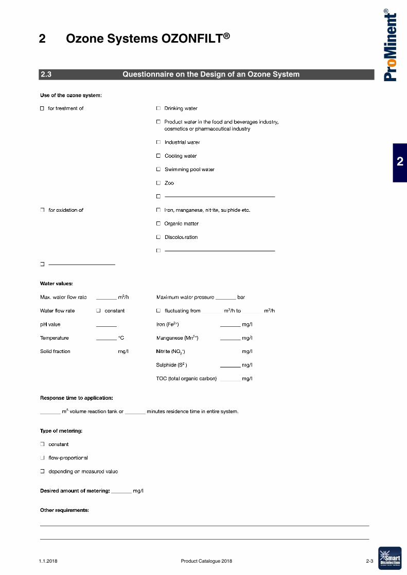
2.3 Questionnaire on the Design of an Ozone System
1.1.2018 Product Catalogue 2018 2-3
2 Ozone Systems OZONFILT®
2
Generate ozone from compressed air or oxygen. Environmentally-friendly and cost-effective.Ozone capacity 5 – 90 g ozone/h
Ozone systems OZONFILT® OZVa are pressurised systems in which the operating gas – air or oxygen – is fed into the ozone generator under pressure.
Air is used as the operating gas in the ozone system OZONFILT® OZVa type 1 to 4The ozone is generated from the oxygen in the ambient air and simultaneously metered. The integrated air treatment unit is designed as a pressure swing dryer, ensuring that ozone can be generated operationally safely and reliably even with a high level of ambient air humidity with ozone concentrations of up to 20 g/Nm3. Using the suitable mixing equipment, ozone concentrations of between 3 and 12 ppm can be achieved in the water to be treated, depending on the temperature.
Oxygen is used as the operating gas in the ozone system OZONFILT® OZVa type 5 to 7Oxygen operation permits ozone generation with ozone concentrations of up to 150 g/Nm3. Depending on the system type, ozone is produced in 1-3 generators from oxygen provided from special oxygen generators or bottles. Using the suitable mixing equipment, ozone concentrations of up to 90 ppm can be achieved in the water to be treated, depending on the temperature.
Your benefits� Simple operation� Ozone generation independent of pressure and mains voltage� Direct injection without injector system at up to 2 bar back pressure� Maximum efficiency with minimal consumption of energy and cooling water� Complete protection of electrical components (high-voltage transformer and power stage) thanks to
PCC technology (primary current-controlled)� Low maintenance and operating costs� Infinitely precise output control of between 3% and 100% of the nominal power with display of the ozone
volume in "grammes/hour"
Technical Details� Compact mounting in painted steel cabinet or optionally in a stainless steel cabinet� Wall cabinet for OZVa 1, 2 and 5; free-standing cabinet for OZVa 3, 4, 6 and 7� Special dielectric with outstanding cooling performance: in spite of the low cooling water consumption,
heat is quickly and efficiently discharged before the ozone produced can decompose due to excessive heat
� Different designs up to complete equipment including integral mixing unit� Excellent efficiency: Over 90% of the ozone is dissolved in the water, thanks to the special construction
of the mixing unit� Pause input for external switching on/off� Analogue input 4-20 mA for power control depending on the measured value combined with external
measuring and control technology� Digital inputs for connection of a gas detector or external fault alarm� Digital alarm signal output� Air conditioning: With ambient temperature above 40 °C, the system can be equipped with an integral
air conditioner. Max. ambient temperature with air conditioning: 50 °C
Field of application� Potable water supply: Oxidation of iron, manganese and arsenic, refinement and taste enhancement
and disinfection� Waste water treatment: Degradation/reduction of COD and microcontaminants, reduction of sewage
sludge� Food and beverage industry: Oxidation of iron and manganese, disinfection of potable water and
rinser water� Public swimming pools: Degradation of disinfection by-products, reliable microbiological barrier and
production of crystal-clear water thanks to its microflocculating effect� Industry: Legionella prevention and disinfection of cooling water
2.4 Ozone System OZONFILT®OZVa
The OZONFILT® OZVa is high-performance and compact. For efficient ozone generation in the medium output range of up to 90 g/h from compressed air or oxygen.
2-4 Product Catalogue 2018 1.1.2018
2 Ozone Systems OZONFILT®
2
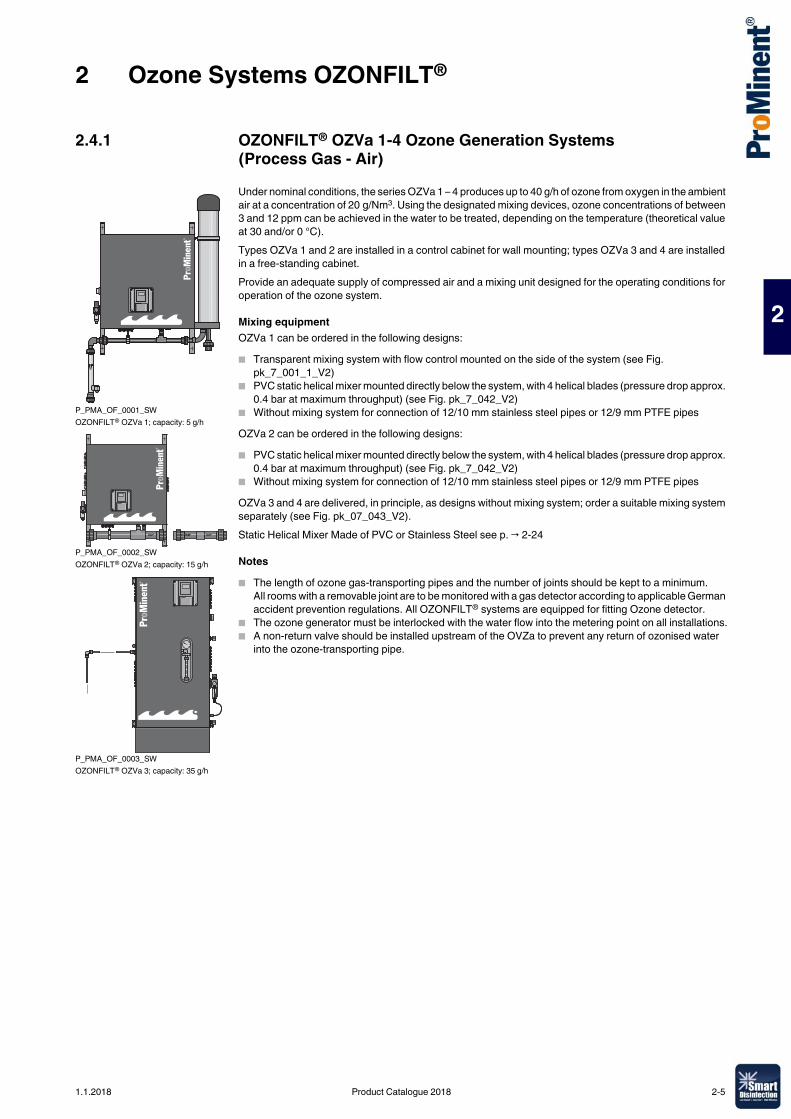
2.4.1 OZONFILT® OZVa 1-4 Ozone Generation Systems (Process Gas - Air)Under nominal conditions, the series OZVa 1 – 4 produces up to 40 g/h of ozone from oxygen in the ambient air at a concentration of 20 g/Nm3. Using the designated mixing devices, ozone concentrations of between 3 and 12 ppm can be achieved in the water to be treated, depending on the temperature (theoretical value at 30 and/or 0 °C).Types OZVa 1 and 2 are installed in a control cabinet for wall mounting; types OZVa 3 and 4 are installed in a free-standing cabinet.Provide an adequate supply of compressed air and a mixing unit designed for the operating conditions for operation of the ozone system.
Mixing equipmentOZVa 1 can be ordered in the following designs:� Transparent mixing system with flow control mounted on the side of the system (see Fig.
pk_7_001_1_V2)� PVC static helical mixer mounted directly below the system, with 4 helical blades (pressure drop approx.
0.4 bar at maximum throughput) (see Fig. pk_7_042_V2)� Without mixing system for connection of 12/10 mm stainless steel pipes or 12/9 mm PTFE pipesOZVa 2 can be ordered in the following designs:� PVC static helical mixer mounted directly below the system, with 4 helical blades (pressure drop approx.
0.4 bar at maximum throughput) (see Fig. pk_7_042_V2)� Without mixing system for connection of 12/10 mm stainless steel pipes or 12/9 mm PTFE pipesOZVa 3 and 4 are delivered, in principle, as designs without mixing system; order a suitable mixing system separately (see Fig. pk_07_043_V2).Static Helical Mixer Made of PVC or Stainless Steel see p. → 2-24
Notes� The length of ozone gas-transporting pipes and the number of joints should be kept to a minimum.
All rooms with a removable joint are to be monitored with a gas detector according to applicable German accident prevention regulations. All OZONFILT® systems are equipped for fitting Ozone detector.
� The ozone generator must be interlocked with the water flow into the metering point on all installations.� A non-return valve should be installed upstream of the OVZa to prevent any return of ozonised water
into the ozone-transporting pipe.
P_PMA_OF_0001_SWOZONFILT® OZVa 1; capacity: 5 g/h
P_PMA_OF_0002_SWOZONFILT® OZVa 2; capacity: 15 g/h
P_PMA_OF_0003_SWOZONFILT® OZVa 3; capacity: 35 g/h
1.1.2018 Product Catalogue 2018 2-5
2 Ozone Systems OZONFILT®
2
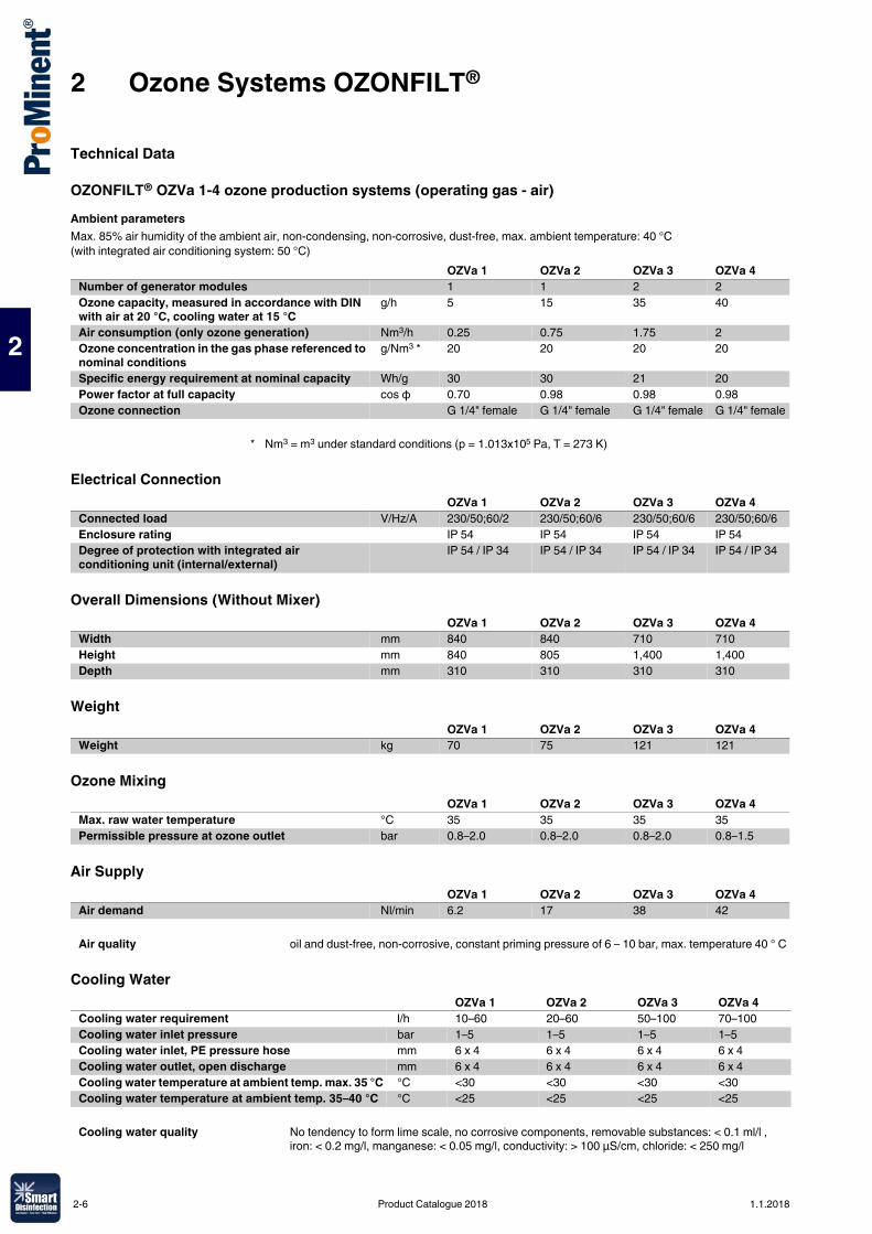
Technical Data
OZONFILT® OZVa 1-4 ozone production systems (operating gas - air)Ambient parametersMax. 85% air humidity of the ambient air, non-condensing, non-corrosive, dust-free, max. ambient temperature: 40 °C (with integrated air conditioning system: 50 °C)
Electrical Connection
Overall Dimensions (Without Mixer)
Weight
Ozone Mixing
Air Supply
Cooling Water
OZVa 1 OZVa 2 OZVa 3 OZVa 4Number of generator modules 1 1 2 2Ozone capacity, measured in accordance with DIN with air at 20 °C, cooling water at 15 °C
g/h 5 15 35 40
Air consumption (only ozone generation) Nm3/h 0.25 0.75 1.75 2Ozone concentration in the gas phase referenced to nominal conditions
g/Nm3 * 20 20 20 20
Specific energy requirement at nominal capacity Wh/g 30 30 21 20Power factor at full capacity cos φ 0.70 0.98 0.98 0.98Ozone connection G 1/4" female G 1/4" female G 1/4" female G 1/4" female
* Nm3 = m3 under standard conditions (p = 1.013x10⁵ Pa, T = 273 K)
OZVa 1 OZVa 2 OZVa 3 OZVa 4Connected load V/Hz/A 230/50;60/2 230/50;60/6 230/50;60/6 230/50;60/6Enclosure rating IP 54 IP 54 IP 54 IP 54Degree of protection with integrated air conditioning unit (internal/external)
IP 54 / IP 34 IP 54 / IP 34 IP 54 / IP 34 IP 54 / IP 34
OZVa 1 OZVa 2 OZVa 3 OZVa 4Width mm 840 840 710 710Height mm 840 805 1,400 1,400Depth mm 310 310 310 310
OZVa 1 OZVa 2 OZVa 3 OZVa 4Weight kg 70 75 121 121
OZVa 1 OZVa 2 OZVa 3 OZVa 4Max. raw water temperature °C 35 35 35 35Permissible pressure at ozone outlet bar 0.8–2.0 0.8–2.0 0.8–2.0 0.8–1.5
OZVa 1 OZVa 2 OZVa 3 OZVa 4Air demand Nl/min 6.2 17 38 42
Air quality oil and dust-free, non-corrosive, constant priming pressure of 6 – 10 bar, max. temperature 40 ° C
OZVa 1 OZVa 2 OZVa 3 OZVa 4Cooling water requirement l/h 10–60 20–60 50–100 70–100Cooling water inlet pressure bar 1–5 1–5 1–5 1–5Cooling water inlet, PE pressure hose mm 6 x 4 6 x 4 6 x 4 6 x 4Cooling water outlet, open discharge mm 6 x 4 6 x 4 6 x 4 6 x 4Cooling water temperature at ambient temp. max. 35 °C °C <30 <30 <30 <30Cooling water temperature at ambient temp. 35–40 °C °C <25 <25 <25 <25
Cooling water quality No tendency to form lime scale, no corrosive components, removable substances: < 0.1 ml/l , iron: < 0.2 mg/l, manganese: < 0.05 mg/l, conductivity: > 100 µS/cm, chloride: < 250 mg/l
2-6 Product Catalogue 2018 1.1.2018
2 Ozone Systems OZONFILT®
2
2.4.2 OZONFILT® OZVa 5-7 Ozone Production Systems (Operating Gas - Oxygen)The product range OZONFILT® OZVa 5 – 7 is a new development based on proven PSG technology, which produces ozone concentrations of up to 150 g/Nm3 using oxygen as the operating gas. Using the designated mixing units, ozone concentrations of up to 90 ppm can be achieved (theoretical value at 0 °C) in the water to be treated.Depending on the system type, ozone is produced in 1 – 3 generators from oxygen, provided from special oxygen generators or bottles. The nominal capacity of the individual generators is 30 g/h at 100 g/Nm3.Type 5 is installed in a wall-mounted cabinet, types 6 and 7 are installed in a free-standing cabinet. In all three systems, ozone is transported to the mixing unit through a separate 12/10 mm stainless steel pipe or 12/9 mm PTFE pipe.
Mixing equipmentWe recommend using stainless steel mixing systems because of the high ozone concentrations. Mixing systems made of PVC can have a reduced service life, depending on the operating conditions.
Important note� Keep the length of pipes for conveying ozone and the number of joints to a minimum. Monitor all
adjoining rooms with a gas detector, in line with the applicable German accident prevention regulations. All OZONFILT® systems are equipped for the fitting of a gas detector, such as type GMA 36 Ozone.
� Depending on the operating and installation conditions, it might also be necessary to monitor the room air for excessive oxygen content.
� It is necessary for the ozone generation system to be interlocked with the water flow to the ozone metering on all installations.
� Install a non-return valve upstream of the OZVa to prevent any backflow of ozonised water into the pipe transporting the ozone.
� Ensure that all accessories that transport gas are resistant to ozone and oxygen (e.g. grease-free).� Only use catalytic residual ozone destructors because of the high ozone concentrations. Activated
charcoal based residual ozone destructors ignite spontaneously if subjected to increased ozone concentrations.
Room Air Monitoring see p. → 2-26
1.1.2018 Product Catalogue 2018 2-7
2 Ozone Systems OZONFILT®
2
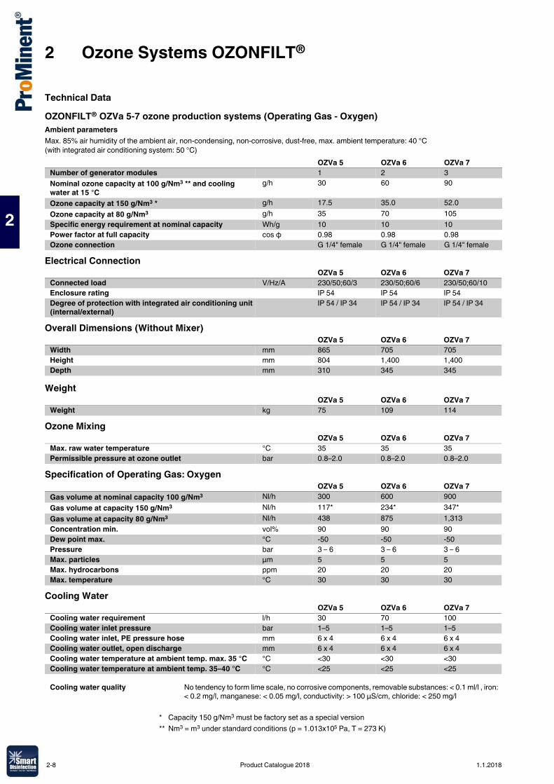
Technical DataOZONFILT® OZVa 5-7 ozone production systems (Operating Gas - Oxygen)Ambient parametersMax. 85% air humidity of the ambient air, non-condensing, non-corrosive, dust-free, max. ambient temperature: 40 °C (with integrated air conditioning system: 50 °C)
Electrical Connection
Overall Dimensions (Without Mixer)
Weight
Ozone Mixing
Specification of Operating Gas: Oxygen
Cooling Water
OZVa 5 OZVa 6 OZVa 7Number of generator modules 1 2 3Nominal ozone capacity at 100 g/Nm3 ** and cooling water at 15 °C
g/h 30 60 90
Ozone capacity at 150 g/Nm3 * g/h 17.5 35.0 52.0Ozone capacity at 80 g/Nm3 g/h 35 70 105Specific energy requirement at nominal capacity Wh/g 10 10 10Power factor at full capacity cos φ 0.98 0.98 0.98Ozone connection G 1/4" female G 1/4" female G 1/4" female
OZVa 5 OZVa 6 OZVa 7Connected load V/Hz/A 230/50;60/3 230/50;60/6 230/50;60/10Enclosure rating IP 54 IP 54 IP 54Degree of protection with integrated air conditioning unit (internal/external)
IP 54 / IP 34 IP 54 / IP 34 IP 54 / IP 34
OZVa 5 OZVa 6 OZVa 7Width mm 865 705 705Height mm 804 1,400 1,400Depth mm 310 345 345
OZVa 5 OZVa 6 OZVa 7Weight kg 75 109 114
OZVa 5 OZVa 6 OZVa 7Max. raw water temperature °C 35 35 35Permissible pressure at ozone outlet bar 0.8–2.0 0.8–2.0 0.8–2.0
OZVa 5 OZVa 6 OZVa 7Gas volume at nominal capacity 100 g/Nm3 Nl/h 300 600 900Gas volume at capacity 150 g/Nm3 Nl/h 117* 234* 347*Gas volume at capacity 80 g/Nm3 Nl/h 438 875 1,313Concentration min. vol% 90 90 90Dew point max. °C -50 -50 -50Pressure bar 3 – 6 3 – 6 3 – 6Max. particles µm 5 5 5Max. hydrocarbons ppm 20 20 20Max. temperature °C 30 30 30
OZVa 5 OZVa 6 OZVa 7Cooling water requirement l/h 30 70 100Cooling water inlet pressure bar 1–5 1–5 1–5Cooling water inlet, PE pressure hose mm 6 x 4 6 x 4 6 x 4Cooling water outlet, open discharge mm 6 x 4 6 x 4 6 x 4Cooling water temperature at ambient temp. max. 35 °C °C <30 <30 <30Cooling water temperature at ambient temp. 35–40 °C °C <25 <25 <25
Cooling water quality No tendency to form lime scale, no corrosive components, removable substances: < 0.1 ml/l , iron: < 0.2 mg/l, manganese: < 0.05 mg/l, conductivity: > 100 µS/cm, chloride: < 250 mg/l
* Capacity 150 g/Nm3 must be factory set as a special version** Nm3 = m3 under standard conditions (p = 1.013x10⁵ Pa, T = 273 K)
2-8 Product Catalogue 2018 1.1.2018
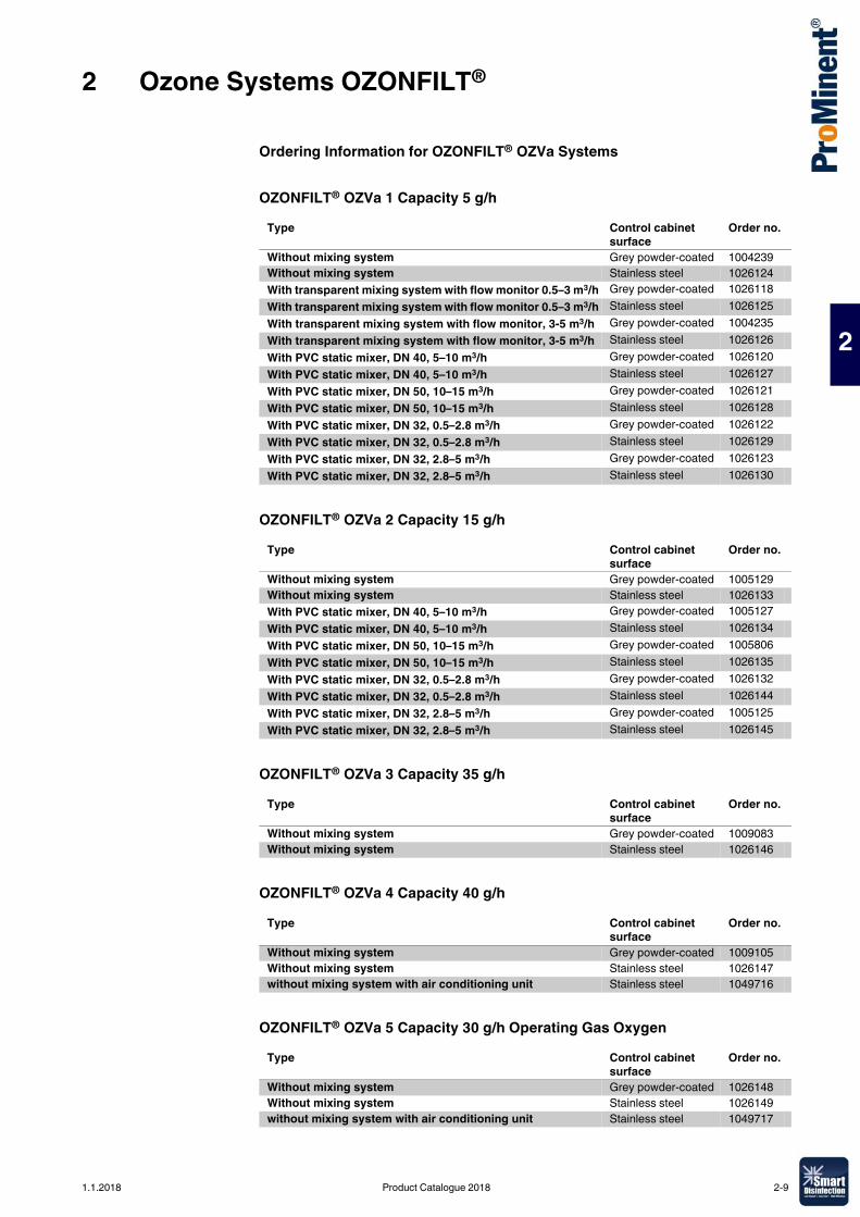
2 Ozone Systems OZONFILT®
2
Ordering Information for OZONFILT® OZVa Systems
OZONFILT® OZVa 1 Capacity 5 g/h
OZONFILT® OZVa 2 Capacity 15 g/h
OZONFILT® OZVa 3 Capacity 35 g/h
OZONFILT® OZVa 4 Capacity 40 g/h
OZONFILT® OZVa 5 Capacity 30 g/h Operating Gas Oxygen
Type Control cabinet surface
Order no.
Without mixing system Grey powder-coated 1004239Without mixing system Stainless steel 1026124With transparent mixing system with flow monitor 0.5–3 m3/h Grey powder-coated 1026118With transparent mixing system with flow monitor 0.5–3 m3/h Stainless steel 1026125With transparent mixing system with flow monitor, 3-5 m3/h Grey powder-coated 1004235With transparent mixing system with flow monitor, 3-5 m3/h Stainless steel 1026126With PVC static mixer, DN 40, 5–10 m3/h Grey powder-coated 1026120With PVC static mixer, DN 40, 5–10 m3/h Stainless steel 1026127With PVC static mixer, DN 50, 10–15 m3/h Grey powder-coated 1026121With PVC static mixer, DN 50, 10–15 m3/h Stainless steel 1026128With PVC static mixer, DN 32, 0.5–2.8 m3/h Grey powder-coated 1026122With PVC static mixer, DN 32, 0.5–2.8 m3/h Stainless steel 1026129With PVC static mixer, DN 32, 2.8–5 m3/h Grey powder-coated 1026123With PVC static mixer, DN 32, 2.8–5 m3/h Stainless steel 1026130
Type Control cabinet surface
Order no.
Without mixing system Grey powder-coated 1005129Without mixing system Stainless steel 1026133With PVC static mixer, DN 40, 5–10 m3/h Grey powder-coated 1005127With PVC static mixer, DN 40, 5–10 m3/h Stainless steel 1026134With PVC static mixer, DN 50, 10–15 m3/h Grey powder-coated 1005806With PVC static mixer, DN 50, 10–15 m3/h Stainless steel 1026135With PVC static mixer, DN 32, 0.5–2.8 m3/h Grey powder-coated 1026132With PVC static mixer, DN 32, 0.5–2.8 m3/h Stainless steel 1026144With PVC static mixer, DN 32, 2.8–5 m3/h Grey powder-coated 1005125With PVC static mixer, DN 32, 2.8–5 m3/h Stainless steel 1026145
Type Control cabinet surface
Order no.
Without mixing system Grey powder-coated 1009083Without mixing system Stainless steel 1026146
Type Control cabinet surface
Order no.
Without mixing system Grey powder-coated 1009105Without mixing system Stainless steel 1026147without mixing system with air conditioning unit Stainless steel 1049716
Type Control cabinet surface
Order no.
Without mixing system Grey powder-coated 1026148Without mixing system Stainless steel 1026149without mixing system with air conditioning unit Stainless steel 1049717
1.1.2018 Product Catalogue 2018 2-9
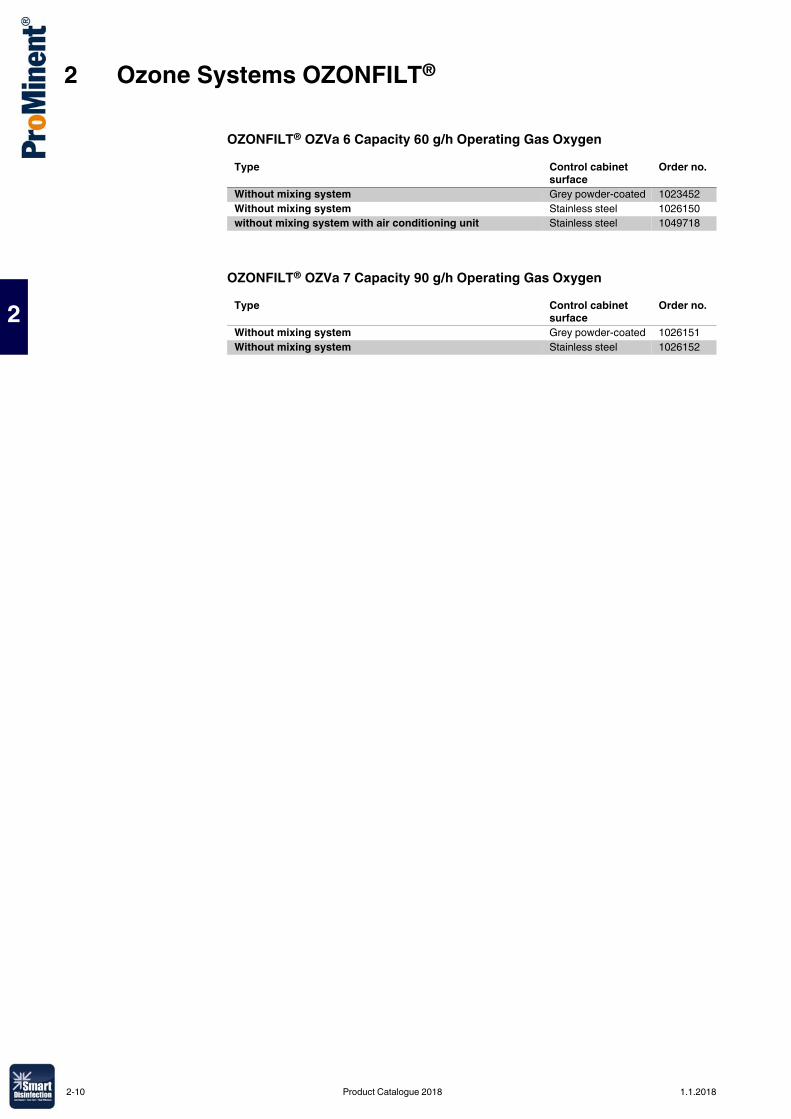
2 Ozone Systems OZONFILT®
2
OZONFILT® OZVa 6 Capacity 60 g/h Operating Gas Oxygen
OZONFILT® OZVa 7 Capacity 90 g/h Operating Gas Oxygen
Type Control cabinet surface
Order no.
Without mixing system Grey powder-coated 1023452Without mixing system Stainless steel 1026150without mixing system with air conditioning unit Stainless steel 1049718
Type Control cabinet surface
Order no.
Without mixing system Grey powder-coated 1026151Without mixing system Stainless steel 1026152
2-10 Product Catalogue 2018 1.1.2018
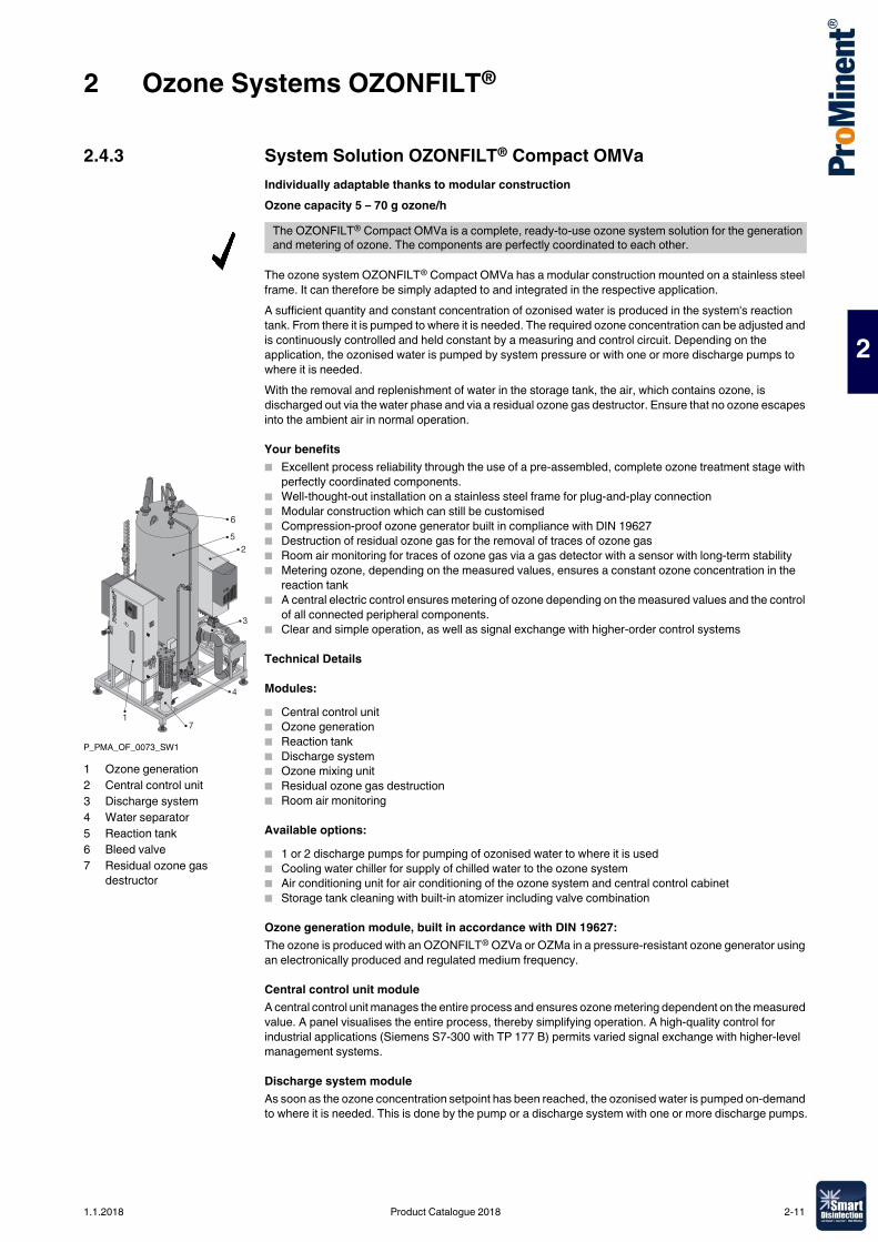
2 Ozone Systems OZONFILT®
2
2.4.3 System Solution OZONFILT® Compact OMVaIndividually adaptable thanks to modular constructionOzone capacity 5 – 70 g ozone/h
The ozone system OZONFILT® Compact OMVa has a modular construction mounted on a stainless steel frame. It can therefore be simply adapted to and integrated in the respective application.A sufficient quantity and constant concentration of ozonised water is produced in the system's reaction tank. From there it is pumped to where it is needed. The required ozone concentration can be adjusted and is continuously controlled and held constant by a measuring and control circuit. Depending on the application, the ozonised water is pumped by system pressure or with one or more discharge pumps to where it is needed.With the removal and replenishment of water in the storage tank, the air, which contains ozone, is discharged out via the water phase and via a residual ozone gas destructor. Ensure that no ozone escapes into the ambient air in normal operation.
Your benefits� Excellent process reliability through the use of a pre-assembled, complete ozone treatment stage with
perfectly coordinated components.� Well-thought-out installation on a stainless steel frame for plug-and-play connection� Modular construction which can still be customised� Compression-proof ozone generator built in compliance with DIN 19627� Destruction of residual ozone gas for the removal of traces of ozone gas� Room air monitoring for traces of ozone gas via a gas detector with a sensor with long-term stability� Metering ozone, depending on the measured values, ensures a constant ozone concentration in the
reaction tank� A central electric control ensures metering of ozone depending on the measured values and the control
of all connected peripheral components.� Clear and simple operation, as well as signal exchange with higher-order control systems
Technical Details
Modules:� Central control unit� Ozone generation� Reaction tank� Discharge system� Ozone mixing unit� Residual ozone gas destruction� Room air monitoring
Available options:� 1 or 2 discharge pumps for pumping of ozonised water to where it is used� Cooling water chiller for supply of chilled water to the ozone system� Air conditioning unit for air conditioning of the ozone system and central control cabinet� Storage tank cleaning with built-in atomizer including valve combination
Ozone generation module, built in accordance with DIN 19627:The ozone is produced with an OZONFILT® OZVa or OZMa in a pressure-resistant ozone generator using an electronically produced and regulated medium frequency.
Central control unit moduleA central control unit manages the entire process and ensures ozone metering dependent on the measured value. A panel visualises the entire process, thereby simplifying operation. A high-quality control for industrial applications (Siemens S7-300 with TP 177 B) permits varied signal exchange with higher-level management systems.
Discharge system moduleAs soon as the ozone concentration setpoint has been reached, the ozonised water is pumped on-demand to where it is needed. This is done by the pump or a discharge system with one or more discharge pumps.
The OZONFILT® Compact OMVa is a complete, ready-to-use ozone system solution for the generation and metering of ozone. The components are perfectly coordinated to each other.
P_PMA_OF_0073_SW1
65
2
3
4
71
1 Ozone generation2 Central control unit3 Discharge system4 Water separator5 Reaction tank6 Bleed valve7 Residual ozone gas
destructor
1.1.2018 Product Catalogue 2018 2-11
2 Ozone Systems OZONFILT®
2
Ozone mixing module:This module comprises an ozone metering point and a downstream mixing section made of stainless steel, with a series of static mixing elements for intensive mixing of the ozone/air mix with the water to be treated. The lines carrying the ozone, and the pipework from the raw water connection to the inlet to the reaction tank are made throughout in stainless steel and have been factory-pressure tested.An injector for sucking out the ozone is not needed with back pressures of up to 1.8 bar because the ozone is generated at positive pressure.
Reaction tank module:The stainless steel reaction tank incorporates all the necessary fittings for water distribution and an automatic bleed valve. The ozone generation module, residual ozone gas destructor module and room air monitoring module are mounted on this storage tank.
Residual ozone gas destruction module:The residual ozone gas destruction module has an integrated water separator to remove any traces of ozone gas in the exhaust air coming from the reaction tank.
Room air monitoring module:The room air is monitored for traces of ozone gas using a calibrated gas detector with a long-term stable electrochemical sensor.If the alarm threshold is exceeded, ozone generation is stopped and an alarm signalled. A buzzer is activated at the same time.
Field of application� Food and beverage industry: Oxidation of iron and manganese, disinfection of potable water and
rinser water� Swimming pools: Degradation of disinfection by-products, reliable microbiological barrier and
production of crystal-clear water thanks to its microflocculating effect
Technical DataType OMVa 5 – 200 OMVa 15 – 500 OMVa 35-1,000 OMVa 40-1,000 OMVa 70-2,000Type: ozone generation system OZVa 1 OZVa 2 OZVa 3 OZVa 4 OZMa 1AOzone output at 20 g/Nm3 g/h 5 15 35 40 70Cooling water volume (15 °C) l/h 10–60 20–60 50–100 70–100 90Nominal flow rate m3/h 1.5 – 5 5 – 15 15 – 30 30 – 45 45 – 60Enclosure rating IP 54 IP 54 IP 54 IP 54 IP 54Connected load V/Hz/A 230/50;60 230/50;60 230/50;60 230/50;60 230/50;60
2-12 Product Catalogue 2018 1.1.2018
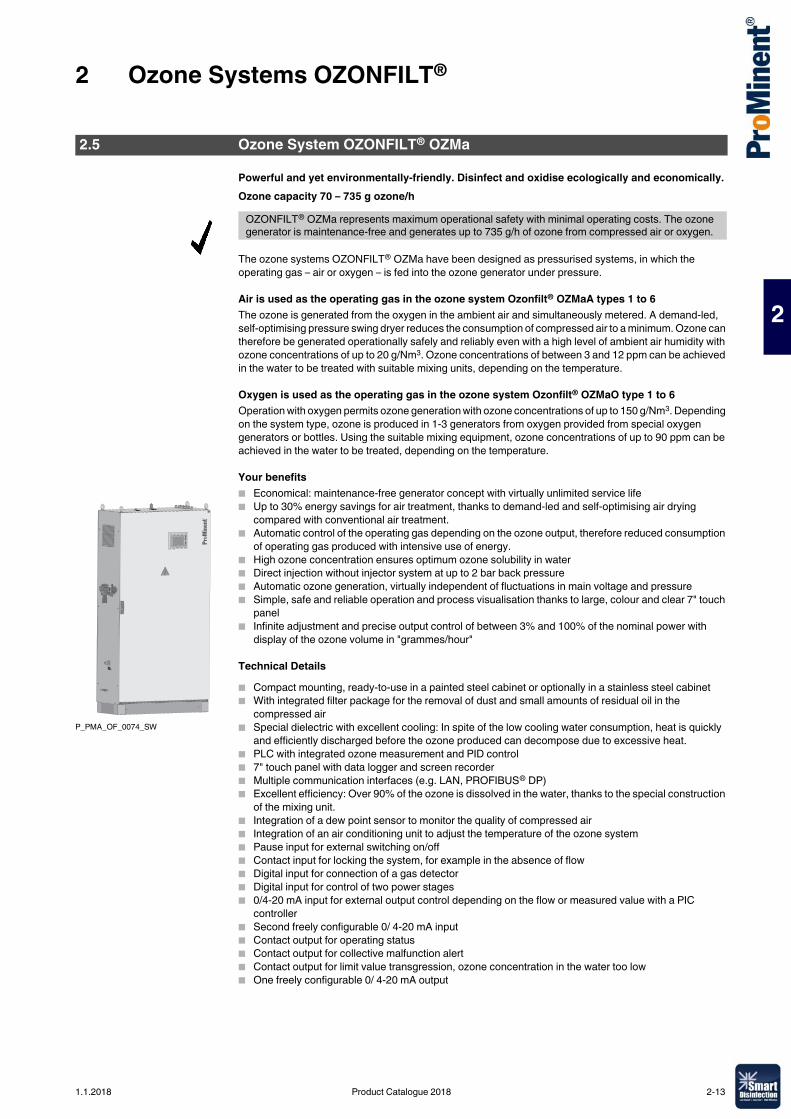
2 Ozone Systems OZONFILT®
2
Powerful and yet environmentally-friendly. Disinfect and oxidise ecologically and economically.Ozone capacity 70 – 735 g ozone/h
The ozone systems OZONFILT® OZMa have been designed as pressurised systems, in which the operating gas – air or oxygen – is fed into the ozone generator under pressure.
Air is used as the operating gas in the ozone system Ozonfilt® OZMaA types 1 to 6The ozone is generated from the oxygen in the ambient air and simultaneously metered. A demand-led, self-optimising pressure swing dryer reduces the consumption of compressed air to a minimum. Ozone can therefore be generated operationally safely and reliably even with a high level of ambient air humidity with ozone concentrations of up to 20 g/Nm3. Ozone concentrations of between 3 and 12 ppm can be achieved in the water to be treated with suitable mixing units, depending on the temperature.
Oxygen is used as the operating gas in the ozone system Ozonfilt® OZMaO type 1 to 6Operation with oxygen permits ozone generation with ozone concentrations of up to 150 g/Nm3. Depending on the system type, ozone is produced in 1-3 generators from oxygen provided from special oxygen generators or bottles. Using the suitable mixing equipment, ozone concentrations of up to 90 ppm can be achieved in the water to be treated, depending on the temperature.
Your benefits� Economical: maintenance-free generator concept with virtually unlimited service life� Up to 30% energy savings for air treatment, thanks to demand-led and self-optimising air drying
compared with conventional air treatment.� Automatic control of the operating gas depending on the ozone output, therefore reduced consumption
of operating gas produced with intensive use of energy.� High ozone concentration ensures optimum ozone solubility in water� Direct injection without injector system at up to 2 bar back pressure� Automatic ozone generation, virtually independent of fluctuations in main voltage and pressure� Simple, safe and reliable operation and process visualisation thanks to large, colour and clear 7" touch
panel� Infinite adjustment and precise output control of between 3% and 100% of the nominal power with
display of the ozone volume in "grammes/hour"
Technical Details� Compact mounting, ready-to-use in a painted steel cabinet or optionally in a stainless steel cabinet � With integrated filter package for the removal of dust and small amounts of residual oil in the
compressed air� Special dielectric with excellent cooling: In spite of the low cooling water consumption, heat is quickly
and efficiently discharged before the ozone produced can decompose due to excessive heat.� PLC with integrated ozone measurement and PID control� 7" touch panel with data logger and screen recorder� Multiple communication interfaces (e.g. LAN, PROFIBUS® DP)� Excellent efficiency: Over 90% of the ozone is dissolved in the water, thanks to the special construction
of the mixing unit.� Integration of a dew point sensor to monitor the quality of compressed air� Integration of an air conditioning unit to adjust the temperature of the ozone system� Pause input for external switching on/off� Contact input for locking the system, for example in the absence of flow� Digital input for connection of a gas detector� Digital input for control of two power stages � 0/4-20 mA input for external output control depending on the flow or measured value with a PIC
controller� Second freely configurable 0/ 4-20 mA input � Contact output for operating status� Contact output for collective malfunction alert� Contact output for limit value transgression, ozone concentration in the water too low� One freely configurable 0/ 4-20 mA output
2.5 Ozone System OZONFILT® OZMa
OZONFILT® OZMa represents maximum operational safety with minimal operating costs. The ozone generator is maintenance-free and generates up to 735 g/h of ozone from compressed air or oxygen.
P_PMA_OF_0074_SW
1.1.2018 Product Catalogue 2018 2-13
2 Ozone Systems OZONFILT®
2
Field of application� Potable water supply: Oxidation of iron, manganese and arsenic, refinement and taste enhancement
and disinfection� Waste water treatment: Degradation/reduction of COD and microcontaminants, reduction of sewage
sludge� Food and beverage industry: Oxidation of iron and manganese, disinfection of potable water and
rinser water� Swimming pools: Degradation of disinfection by-products, reliable microbiological barrier and
production of crystal-clear water thanks to its microflocculating effect� Industry: Legionella prevention and disinfection of cooling water
2-14 Product Catalogue 2018 1.1.2018
2 Ozone Systems OZONFILT®
2
2.5.1 Ozone Generation Systems OZONFILT® OZMa 1-6 A (Operating Gas - Air)Under nominal conditions, the OZMa 1-6 A range produces up to 420 g/h of ozone from compressed air at a concentration of 20 g/Nm3. Using the designated mixing devices, ozone concentrations of between 3 and 12 ppm can be achieved in the water to be treated, depending on the temperature (theoretical value at 30 or 0 °C).Different feature options can be achieved by combining different Identity code characteristics.The plants are pre-mounted ready for connection in a painted steel cabinet (optional stainless steel control cabinet) and need only be connected to a single-phase voltage supply, compressed air, cooling water/waste water and ozone metering point on the customer's site.An adequate compressed air supply and a mixing device designed for the operating conditions should be integrated for operation of the ozone plant.Ordering Information for OZONFILT® OZMa Systems see p. → 2-21, Static Helical Mixer Made of PVC or Stainless Steel see p. → 2-24
Mixing equipmentAll OZMa systems are delivered, in principle, without a mixing unit and a suitable mixing system has to be ordered separately. When selecting a suitable mixing system, please note that the mixing of ozone is more efficient the higher the water flow in the mixing system. Accordingly design the mixing system so that the flow of the water to be treated is at the upper range of the flow specification.Static Helical Mixer Made of PVC or Stainless Steel see p. → 2-24
Notes on installationKeep the length of ozone gas transporting pipes and the number of joints to a minimum. All rooms with a removable joint should be monitored with a gas detector in line with the applicable German accident prevention regulations. All OZONFILT® systems are equipped for fitting Ozone detector.Ozonisation adds a large amount of gas to the water of which only a small percentage can dissolve. Adequate bleeding should therefore be integrated. Because the gases discharged in this way have a considerable residual ozone concentration, appropriate residual ozone destructors should be installed.The ozone generator should be interlocked with the water flow into the metering point for all installations.A non-return valve should be installed between OZMa and the ozone metering point to prevent any return of ozonised water into the ozone-transporting pipe.Room Air Monitoring see p. → 2-26, Residual Ozone Gas Destructor see p. → 2-25
P_PMA_OF_0074_SW
1.1.2018 Product Catalogue 2018 2-15
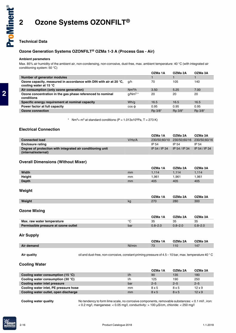
2 Ozone Systems OZONFILT®
2
Technical Data
Ozone Generation Systems OZONFILT® OZMa 1-3 A (Process Gas - Air)Ambient parametersMax. 85% air humidity of the ambient air, non-condensing, non-corrosive, dust-free, max. ambient temperature: 40 °C (with integrated air conditioning system: 50 °C)
Electrical Connection
Overall Dimensions (Without Mixer)
Weight
Ozone Mixing
Air Supply
Cooling Water
OZMa 1A OZMa 2A OZMa 3ANumber of generator modules 1 1 1Ozone capacity, measured in accordance with DIN with air at 20 °C, cooling water at 15 °C
g/h 70 105 140
Air consumption (only ozone generation) Nm3/h 3.50 5.25 7.00Ozone concentration in the gas phase referenced to nominal conditions
g/Nm3 * 20 20 20
Specific energy requirement at nominal capacity Wh/g 16.5 16.5 16.5Power factor at full capacity cos φ 0.95 0.95 0.95Ozone connection Rp 3/8" Rp 3/8" Rp 3/8"
* Nm3= m3 at standard conditions (P = 1.013x10⁵Pa, T = 273 K)
OZMa 1A OZMa 2A OZMa 3AConnected load V/Hz/A 230/50;60/10 230/50;60/16 230/50;60/16Enclosure rating IP 54 IP 54 IP 54Degree of protection with integrated air conditioning unit (internal/external)
IP 54 / IP 34 IP 54 / IP 34 IP 54 / IP 34
OZMa 1A OZMa 2A OZMa 3AWidth mm 1,114 1,114 1,114Height mm 1,961 1,961 1,961Depth mm 405 405 405
OZMa 1A OZMa 2A OZMa 3AWeight kg 270 280 300
OZMa 1A OZMa 2A OZMa 3AMax. raw water temperature °C 35 35 35Permissible pressure at ozone outlet bar 0.8–2.0 0.8–2.0 0.8–2.0
OZMa 1A OZMa 2A OZMa 3AAir demand Nl/min 73 110 147
Air quality oil and dust-free, non-corrosive, constant priming pressure of 4.5 – 10 bar, max. temperature 40 ° C
OZMa 1A OZMa 2A OZMa 3ACooling water consumption (15 °C) l/h 90 135 180Cooling water consumption (30 °C) l/h 125 190 250Cooling water inlet pressure bar 2–5 2–5 2–5Cooling water inlet, PE pressure hose mm 8 x 5 8 x 5 12 x 9Cooling water outlet, open discharge mm 8 x 5 8 x 5 12 x 9
Cooling water quality No tendency to form lime scale, no corrosive components, removable substances: < 0.1 ml/l , iron: < 0.2 mg/l, manganese: < 0.05 mg/l, conductivity: > 100 µS/cm, chloride: < 250 mg/l
2-16 Product Catalogue 2018 1.1.2018
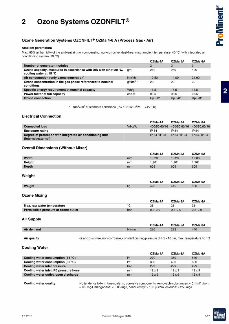
2 Ozone Systems OZONFILT®
2
Ozone Generation Systems OZONFILT® OZMa 4-6 A (Process Gas - Air)Ambient parametersMax. 85% air humidity of the ambient air, non-condensing, non-corrosive, dust-free, max. ambient temperature: 40 °C (with integrated air conditioning system: 50 °C)
Electrical Connection
Overall Dimensions (Without Mixer)
Weight
Ozone Mixing
Air Supply
Cooling Water
OZMa 4A OZMa 5A OZMa 6ANumber of generator modules 2 2 3Ozone capacity, measured in accordance with DIN with air at 20 °C, cooling water at 15 °C
g/h 210 280 420
Air consumption (only ozone generation) Nm3/h 10.50 14.00 21.00Ozone concentration in the gas phase referenced to nominal conditions
g/Nm3 * 20 20 20
Specific energy requirement at nominal capacity Wh/g 16.5 16.5 16.5Power factor at full capacity cos φ 0.95 0.95 0.95Ozone connection Rp 3/8" Rp 3/8" Rp 3/8"
* Nm3= m3 at standard conditions (P = 1.013x10⁵Pa, T = 273 K)
OZMa 4A OZMa 5A OZMa 6AConnected load V/Hz/A 400/50;60/16 400/50;60/16 400/50;60/16Enclosure rating IP 54 IP 54 IP 54Degree of protection with integrated air conditioning unit (internal/external)
IP 54 / IP 34 IP 54 / IP 34 IP 54 / IP 34
OZMa 4A OZMa 5A OZMa 6AWidth mm 1,320 1,320 1,606Height mm 1,961 1,961 1,961Depth mm 605 605 605
OZMa 4A OZMa 5A OZMa 6AWeight kg 420 445 580
OZMa 4A OZMa 5A OZMa 6AMax. raw water temperature °C 35 35 35Permissible pressure at ozone outlet bar 0.8–2.0 0.8–2.0 0.8–2.0
OZMa 4A OZMa 5A OZMa 6AAir demand Nl/min 220 293 440
Air quality oil and dust-free, non-corrosive, constant priming pressure of 4.5 – 10 bar, max. temperature 40 ° C
OZMa 4A OZMa 5A OZMa 6ACooling water consumption (15 °C) l/h 270 360 540Cooling water consumption (30 °C) l/h 300 400 600Cooling water inlet pressure bar 2–5 2–5 2–5Cooling water inlet, PE pressure hose mm 12 x 9 12 x 9 12 x 9Cooling water outlet, open discharge mm 12 x 9 12 x 9 12 x 9
Cooling water quality No tendency to form lime scale, no corrosive components, removable substances: < 0.1 ml/l , iron: < 0.2 mg/l, manganese: < 0.05 mg/l, conductivity: > 100 µS/cm, chloride: < 250 mg/l
1.1.2018 Product Catalogue 2018 2-17
2 Ozone Systems OZONFILT®
2
2.5.2 Ozone Generation Systems OZONFILT® OZMa 1-6 O (Operating Gas - Oxygen)Under nominal conditions, the OZMa 1-6 O range produces up to 735 g/h of ozone from oxygen at a concentration of up to 150 g/Nm3. Using the designated mixing devices, ozone concentrations in the water to be treated of up to 90 ppm can be achieved (theoretical value at 0 °C). Ozone concentration in g/Nm3 and system feed rate in g/h can be varied depending on the operating conditions and can thus be individually matched to the application conditions. Examples for various combinations are listed in the technical data table.Different feature options can be achieved by combining different Identity code characteristics.The systems are pre-mounted ready for connection in a painted steel cabinet (optional stainless steel control cabinet) and should only be connected to a single-phase voltage supply, oxygen, cooling water/waste water and ozone metering point on the customer's site.Ordering Information for OZONFILT® OZMa Systems see p. → 2-21
Mixing equipmentAll OZMa systems are delivered, in principle, without a mixing unit and a suitable mixing system has to be ordered separately. When selecting a suitable mixing system, please note that the mixing of ozone is more efficient the higher the water flow in the mixing system. Accordingly design the mixing system so that the flow of the water to be treated is at the upper range of the flow specification.We recommend using stainless steel mixing systems because of the high ozone concentrations. Mixing systems made of PVC can have a reduced service life, depending on the operating conditions.Static Helical Mixer Made of PVC or Stainless Steel see p. → 2-24
Notes on installationKeep the length of ozone gas transporting pipes and the number of joints to a minimum. All rooms with a removable joint should be monitored with a gas detector in line with the applicable German accident prevention regulations. All OZONFILT® systems are equipped for fitting Ozone detector.Depending on the operating and installation conditions, it might be necessary to also monitor the room air for excessive oxygen content.All gas-transporting accessories should be resistant to ozone and oxygen (e. g. fat-free).Ozonisation adds a large amount of gas to the water of which only a small percentage can dissolve. Adequate bleeding should therefore be integrated. Because the gases discharged this way have a considerable residual ozone concentration, appropriate residual ozone destructors should be installed. Because of the high ozone concentrations, only catalytic residual ozone destructors can be used. Activated charcoal-based residual ozone destructors ignite spontaneously if subjected to increased ozone concentrations.The ozone generator must be interlocked with the water flow into the metering point for all installation.A non-return valve should be installed between OZMa and ozone metering point to prevent any return of ozonised water into the ozone-transporting pipe.Room Air Monitoring see p. → 2-26, Residual Ozone Gas Destructor see p. → 2-25
2-18 Product Catalogue 2018 1.1.2018
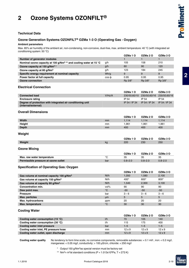
2 Ozone Systems OZONFILT®
2
Technical DataOzone Generation Systems OZONFILT® OZMa 1-3 O (Operating Gas - Oxygen)Ambient parametersMax. 85% air humidity of the ambient air, non-condensing, non-corrosive, dust-free, max. ambient temperature: 40 °C (with integrated air conditioning system: 50 °C)
Electrical Connection
Overall Dimensions
Weight
Ozone Mixing
Specification of Operating Gas: Oxygen
Cooling Water
OZMa 1 O OZMa 2 O OZMa 3 ONumber of generator modules 1 1 1Nominal ozone capacity at 100 g/Nm3 ** and cooling water at 15 °C g/h 105 158 210Ozone capacity at 150 g/Nm3 * g/h 60 90 120Ozone capacity at 80 g/Nm3 g/h 123 184 245Specific energy requirement at nominal capacity Wh/g 9 9 9Power factor at full capacity cos φ 0.95 0.95 0.95Ozone connection Rp 3/8" Rp 3/8" Rp 3/8"
OZMa 1 O OZMa 2 O OZMa 3 OConnected load V/Hz/A 230/50;60/10 230/50;60/16 230/50;60/16Enclosure rating IP 54 IP 54 IP 54Degree of protection with integrated air conditioning unit (internal/external)
IP 54 / IP 34 IP 54 / IP 34 IP 54 / IP 34
OZMa 1 O OZMa 2 O OZMa 3 OWidth mm 1,114 1,114 1,114Height mm 1,961 1,961 1,961Depth mm 400 400 400
OZMa 1 O OZMa 2 O OZMa 3 OWeight kg 220 230 250
OZMa 1 O OZMa 2 O OZMa 3 OMax. raw water temperature °C 35 35 35Permissible pressure at ozone outlet bar 0.8–2.0 0.8–2.0 0.8–2.0
OZMa 1 O OZMa 2 O OZMa 3 OGas volume at nominal capacity 100 g/Nm3 Nl/h 1,050 1,580 2,100Gas volume at capacity 150 g/Nm3 Nl/h 400* 600* 800*Gas volume at capacity 80 g/Nm3 Nl/h 1,540 2,300 3,100Concentration min. vol% 90 90 90Dew point max. °C -50 -50 -50Pressure bar 3 – 6 3 – 6 3 – 6Max. particles µm 5 5 5Max. hydrocarbons ppm 20 20 20Max. temperature °C 30 30 30
OZMa 1 O OZMa 2 O OZMa 3 OCooling water consumption (15 °C) l/h 70 105 140Cooling water consumption (30 °C) l/h 115 175 400Cooling water inlet pressure bar 1–5 1–5 1–5Cooling water inlet, PE pressure hose mm 12 x 9 12 x 9 12 x 9Cooling water outlet, open discharge mm 12 x 9 12 x 9 12 x 9
Cooling water quality No tendency to form lime scale, no corrosive components, removable substances: < 0.1 ml/l , iron: < 0.2 mg/l, manganese: < 0.05 mg/l, conductivity: > 100 µS/cm, chloride: < 250 mg/l
* Output 150 g/Nm3as special version must be factory-set** Nm3= m3at standard conditions (P = 1.013x10⁵Pa, T = 273 K)
1.1.2018 Product Catalogue 2018 2-19
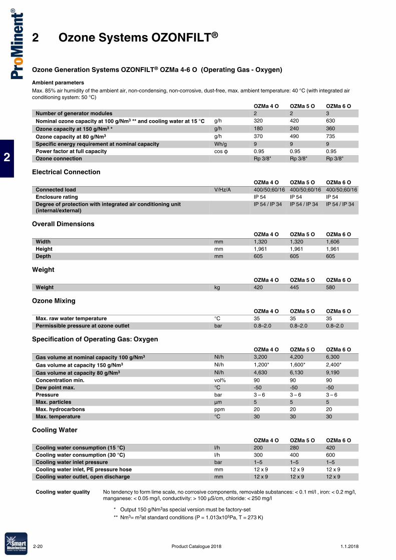
2 Ozone Systems OZONFILT®
2
Ozone Generation Systems OZONFILT® OZMa 4-6 O (Operating Gas - Oxygen)Ambient parametersMax. 85% air humidity of the ambient air, non-condensing, non-corrosive, dust-free, max. ambient temperature: 40 °C (with integrated air conditioning system: 50 °C)
Electrical Connection
Overall Dimensions
Weight
Ozone Mixing
Specification of Operating Gas: Oxygen
Cooling Water
OZMa 4 O OZMa 5 O OZMa 6 ONumber of generator modules 2 2 3Nominal ozone capacity at 100 g/Nm3 ** and cooling water at 15 °C g/h 320 420 630Ozone capacity at 150 g/Nm3 * g/h 180 240 360Ozone capacity at 80 g/Nm3 g/h 370 490 735Specific energy requirement at nominal capacity Wh/g 9 9 9Power factor at full capacity cos φ 0.95 0.95 0.95Ozone connection Rp 3/8" Rp 3/8" Rp 3/8"
OZMa 4 O OZMa 5 O OZMa 6 OConnected load V/Hz/A 400/50;60/16 400/50;60/16 400/50;60/16Enclosure rating IP 54 IP 54 IP 54Degree of protection with integrated air conditioning unit (internal/external)
IP 54 / IP 34 IP 54 / IP 34 IP 54 / IP 34
OZMa 4 O OZMa 5 O OZMa 6 OWidth mm 1,320 1,320 1,606Height mm 1,961 1,961 1,961Depth mm 605 605 605
OZMa 4 O OZMa 5 O OZMa 6 OWeight kg 420 445 580
OZMa 4 O OZMa 5 O OZMa 6 OMax. raw water temperature °C 35 35 35Permissible pressure at ozone outlet bar 0.8–2.0 0.8–2.0 0.8–2.0
OZMa 4 O OZMa 5 O OZMa 6 OGas volume at nominal capacity 100 g/Nm3 Nl/h 3,200 4,200 6,300Gas volume at capacity 150 g/Nm3 Nl/h 1,200* 1,600* 2,400*Gas volume at capacity 80 g/Nm3 Nl/h 4,630 6,130 9,190Concentration min. vol% 90 90 90Dew point max. °C -50 -50 -50Pressure bar 3 – 6 3 – 6 3 – 6Max. particles µm 5 5 5Max. hydrocarbons ppm 20 20 20Max. temperature °C 30 30 30
OZMa 4 O OZMa 5 O OZMa 6 OCooling water consumption (15 °C) l/h 200 280 420Cooling water consumption (30 °C) l/h 300 400 600Cooling water inlet pressure bar 1–5 1–5 1–5Cooling water inlet, PE pressure hose mm 12 x 9 12 x 9 12 x 9Cooling water outlet, open discharge mm 12 x 9 12 x 9 12 x 9
Cooling water quality No tendency to form lime scale, no corrosive components, removable substances: < 0.1 ml/l , iron: < 0.2 mg/l, manganese: < 0.05 mg/l, conductivity: > 100 µS/cm, chloride: < 250 mg/l
* Output 150 g/Nm3as special version must be factory-set** Nm3= m3at standard conditions (P = 1.013x10⁵Pa, T = 273 K)
2-20 Product Catalogue 2018 1.1.2018
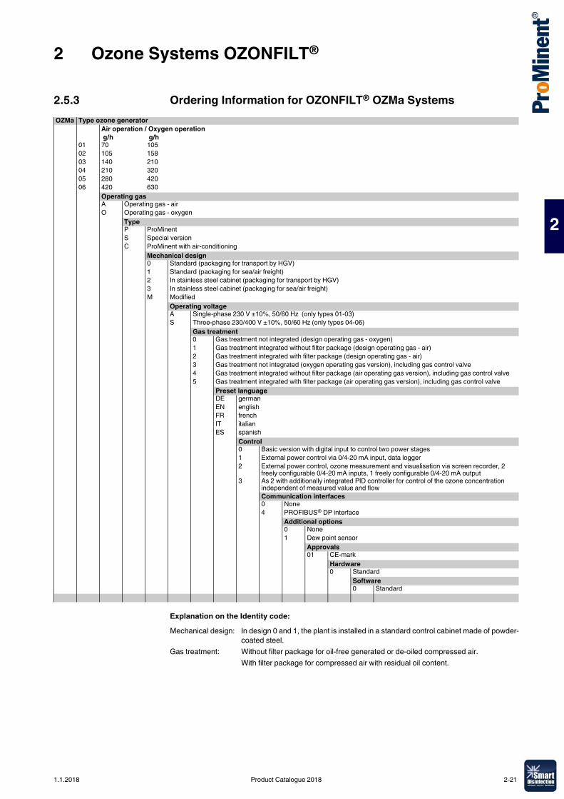
2 Ozone Systems OZONFILT®
2
2.5.3 Ordering Information for OZONFILT® OZMa Systems
Explanation on the Identity code:
OZMa Type ozone generatorAir operation / Oxygen operation g/h g/h
01 70 10502 105 15803 140 21004 210 32005 280 42006 420 630
Operating gasA Operating gas - airO Operating gas - oxygen
TypeP ProMinentS Special versionC ProMinent with air-conditioning
Mechanical design0 Standard (packaging for transport by HGV)1 Standard (packaging for sea/air freight)2 In stainless steel cabinet (packaging for transport by HGV)3 In stainless steel cabinet (packaging for sea/air freight)M Modified
Operating voltageA Single-phase 230 V ±10%, 50/60 Hz (only types 01-03)S Three-phase 230/400 V ±10%, 50/60 Hz (only types 04-06)
Gas treatment0 Gas treatment not integrated (design operating gas - oxygen)1 Gas treatment integrated without filter package (design operating gas - air)2 Gas treatment integrated with filter package (design operating gas - air)3 Gas treatment not integrated (oxygen operating gas version), including gas control valve4 Gas treatment integrated without filter package (air operating gas version), including gas control valve5 Gas treatment integrated with filter package (air operating gas version), including gas control valve
Preset languageDE germanEN englishFR frenchIT italianES spanish
Control0 Basic version with digital input to control two power stages1 External power control via 0/4-20 mA input, data logger2 External power control, ozone measurement and visualisation via screen recorder, 2
freely configurable 0/4-20 mA inputs, 1 freely configurable 0/4-20 mA output3 As 2 with additionally integrated PID controller for control of the ozone concentration
independent of measured value and flowCommunication interfaces0 None4 PROFIBUS® DP interface
Additional options0 None1 Dew point sensor
Approvals01 CE-mark
Hardware0 Standard
Software0 Standard
Mechanical design: In design 0 and 1, the plant is installed in a standard control cabinet made of powder-coated steel.
Gas treatment: Without filter package for oil-free generated or de-oiled compressed air.With filter package for compressed air with residual oil content.
1.1.2018 Product Catalogue 2018 2-21
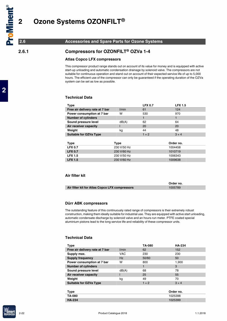
2 Ozone Systems OZONFILT®
2
2.6.1 Compressors for OZONFILT® OZVa 1-4Atlas Copco LFX compressorsThis compressor product range stands out on account of its value for money and is equipped with active start-up unloading and automatic condensation drainage by solenoid valve. The compressors are not suitable for continuous operation and stand out on account of their expected service life of up to 5,000 hours. The efficient use of the compressor can only be guaranteed if the operating duration of the OZVa system can be set as low as possible.
Technical Data
Air filter kit
Dürr ABK compressorsThe outstanding feature of this continuously rated range of compressors is their extremely robust construction, making them ideally suitable for industrial use. They are equipped with active start unloading, automatic condensate discharge by solenoid valve and an hours-run meter. PTFE coated special aluminium pistons lead to the long service life and reliability of these compressor units.
Technical Data
2.6 Accessories and Spare Parts for Ozone Systems
Type LFX 0.7 LFX 1.5Free air delivery rate at 7 bar l/min 61 124Power consumption at 7 bar W 530 970Number of cylinders 1 1Sound pressure level dB(A) 62 64Air receiver capacity l 20 20Weight kg 44 48Suitable for OZVa Type 1 + 2 3 + 4
Type Type Order no.LFX 0.7 230 V/50 Hz 1004458LFX 0.7 230 V/60 Hz 1010719LFX 1.5 230 V/50 Hz 1006343LFX 1.5 230 V/60 Hz 1009638
Order no.Air filter kit for Atlas Copco LFX compressors 1005789
Type TA-080 HA-234Free air delivery rate at 7 bar l/min 62 152Supply max. VAC 230 230Supply frequency Hz 50/60 50Power consumption at 7 bar W 800 1,900Number of cylinders 1 3Sound pressure level dB(A) 68 78Air receiver capacity l 25 55Weight kg 49 70Suitable for OZVa Type 1 + 2 3 + 4
Type Order no.TA-080 1025398HA-234 1025399
2-22 Product Catalogue 2018 1.1.2018
2 Ozone Systems OZONFILT®
2
Air filter kit
* 1 filter kit is required per cylinder.Compressors with refrigeration drying for operation in conditions of high humidity, and high-capacity screw compressors for connection to several ozone plants are available on request.
2.6.2 Oxygen generator for OZONFILT® OZVa 5-7 and OZMa10OXYMAT 020 ecoThis compact oxygen generator works on the principle of pressure swing filtration of the ambient air through a molecular sieve. Oxygen is generated with a purity of up to 95% and a dew point of – 70°C when supplied with suitably dried compressed air. The system generates a pressure of 4 bar at the oxygen outlet and can be connected directly to the OZVa 5-7 or OZMa 10.
Technical Data(At 90% oxygen yield):
Example of an installation
Accessories
Order no.Air filter kit for Dürr ABK compressors* 1025400
Type OXYMAT 020 ecoCapacity 1.6 Nm3/hAir requirement (min. 6 bar) 0.31 Nm3/minPower consumption incl. compressor 2.5 kWSpecific energy requirement 1.4 kWh/Nm3
Quantity Order no.1 Kaeser SX 3 screw compressor (oil-greased), Motor 2.2 kW, integral
cyclone filteron request
3 Connecting set, Hose with quick-release coupling 1/2" – 3/4" external thread at both sides, length 1.2 m
1025388
2 Pressure tank O2 for Oxymat O 020 eco, 90 l, 11 bar, PED with revision opening
1044986
1 Refrigeration dryer ACT 5, 33 Nm3/h, 1/230 – 240 V on request1 Filter set 006, for LE 2-10 and GX 2-10 FF 10253871 Hexagonal reducing piece R 3/4 -Rp 1/2 1.4571 10033661 OXYMAT 020 eco, 110-240 V / 50-60 Hz 10447991 Connecting set with connections for 6x4 mm PTFE hose, between
OXYMAT and OZVa1025395
Order no.PTFE hose 6x4 mm, admissible operating pressure 15 bar, sold in metres 037426Service kit for Atlas Copco LE 2-10, (recommended after 8000 running hours) 1025390Service kit for Atlas Copco GX 2-10 FF, (recommended after 8000 running hours)
1025391
Service kit 006 1025392Maintenance set for screw compressor SX3 on requestMaintenance set for OXYMAT 020 eco on request
1.1.2018 Product Catalogue 2018 2-23
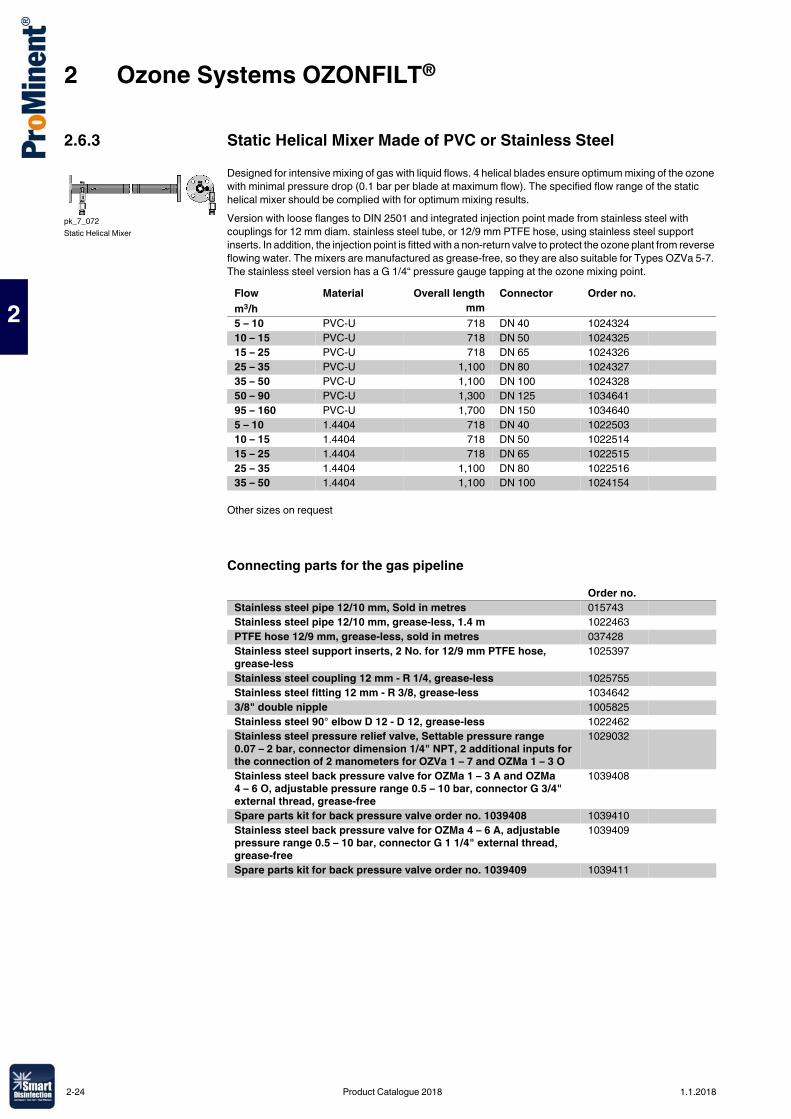
2 Ozone Systems OZONFILT®
2
2.6.3 Static Helical Mixer Made of PVC or Stainless SteelDesigned for intensive mixing of gas with liquid flows. 4 helical blades ensure optimum mixing of the ozone with minimal pressure drop (0.1 bar per blade at maximum flow). The specified flow range of the static helical mixer should be complied with for optimum mixing results.Version with loose flanges to DIN 2501 and integrated injection point made from stainless steel with couplings for 12 mm diam. stainless steel tube, or 12/9 mm PTFE hose, using stainless steel support inserts. In addition, the injection point is fitted with a non-return valve to protect the ozone plant from reverse flowing water. The mixers are manufactured as grease-free, so they are also suitable for Types OZVa 5-7. The stainless steel version has a G 1/4“ pressure gauge tapping at the ozone mixing point.
Other sizes on request
Connecting parts for the gas pipeline
pk_7_072Static Helical Mixer
Flow Material Overall length Connector Order no.m3/h mm5 – 10 PVC-U 718 DN 40 102432410 – 15 PVC-U 718 DN 50 102432515 – 25 PVC-U 718 DN 65 102432625 – 35 PVC-U 1,100 DN 80 102432735 – 50 PVC-U 1,100 DN 100 102432850 – 90 PVC-U 1,300 DN 125 103464195 – 160 PVC-U 1,700 DN 150 10346405 – 10 1.4404 718 DN 40 102250310 – 15 1.4404 718 DN 50 102251415 – 25 1.4404 718 DN 65 102251525 – 35 1.4404 1,100 DN 80 102251635 – 50 1.4404 1,100 DN 100 1024154
Order no.Stainless steel pipe 12/10 mm, Sold in metres 015743Stainless steel pipe 12/10 mm, grease-less, 1.4 m 1022463PTFE hose 12/9 mm, grease-less, sold in metres 037428Stainless steel support inserts, 2 No. for 12/9 mm PTFE hose, grease-less
1025397
Stainless steel coupling 12 mm - R 1/4, grease-less 1025755Stainless steel fitting 12 mm - R 3/8, grease-less 10346423/8" double nipple 1005825Stainless steel 90° elbow D 12 - D 12, grease-less 1022462Stainless steel pressure relief valve, Settable pressure range 0.07 – 2 bar, connector dimension 1/4" NPT, 2 additional inputs for the connection of 2 manometers for OZVa 1 – 7 and OZMa 1 – 3 O
1029032
Stainless steel back pressure valve for OZMa 1 – 3 A and OZMa4 – 6 O, adjustable pressure range 0.5 – 10 bar, connector G 3/4" external thread, grease-free
1039408
Spare parts kit for back pressure valve order no. 1039408 1039410Stainless steel back pressure valve for OZMa 4 – 6 A, adjustable pressure range 0.5 – 10 bar, connector G 1 1/4" external thread, grease-free
1039409
Spare parts kit for back pressure valve order no. 1039409 1039411
2-24 Product Catalogue 2018 1.1.2018
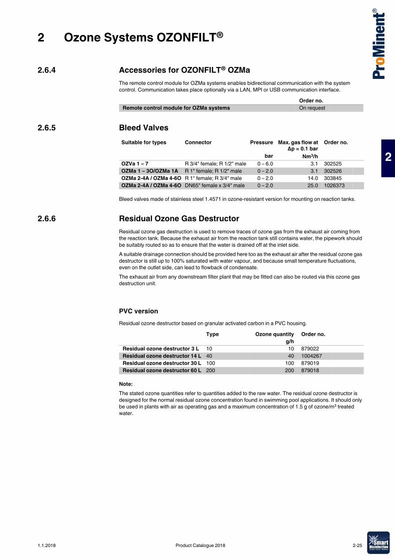
2 Ozone Systems OZONFILT®
2
2.6.4 Accessories for OZONFILT® OZMaThe remote control module for OZMa systems enables bidirectional communication with the system control. Communication takes place optionally via a LAN, MPI or USB communication interface.
2.6.5 Bleed Valves
Bleed valves made of stainless steel 1.4571 in ozone-resistant version for mounting on reaction tanks.
2.6.6 Residual Ozone Gas DestructorResidual ozone gas destruction is used to remove traces of ozone gas from the exhaust air coming from the reaction tank. Because the exhaust air from the reaction tank still contains water, the pipework should be suitably routed so as to ensure that the water is drained off at the inlet side.A suitable drainage connection should be provided here too as the exhaust air after the residual ozone gas destructor is still up to 100% saturated with water vapour, and because small temperature fluctuations, even on the outlet side, can lead to flowback of condensate.The exhaust air from any downstream filter plant that may be fitted can also be routed via this ozone gas destruction unit.
PVC versionResidual ozone destructor based on granular activated carbon in a PVC housing.
Note:The stated ozone quantities refer to quantities added to the raw water. The residual ozone destructor is designed for the normal residual ozone concentration found in swimming pool applications. It should only be used in plants with air as operating gas and a maximum concentration of 1.5 g of ozone/m3 treated water.
Order no.Remote control module for OZMa systems On request
Suitable for types Connector Pressure Max. gas flow atΔp = 0.1 bar
Order no.
bar Nm3/hOZVa 1 – 7 R 3/4" female; R 1/2" male 0 – 6.0 3.1 302525OZMa 1 – 3O/OZMa 1A R 1" female; R 1/2" male 0 – 2.0 3.1 302526OZMa 2-4A / OZMa 4-6O R 1" female; R 3/4" male 0 – 2.0 14.0 303845OZMa 2-4A / OZMa 4-6O DN65" female x 3/4" male 0 – 2.0 25.0 1026373
Type Ozone quantity Order no. g/h
Residual ozone destructor 3 L 10 10 879022Residual ozone destructor 14 L 40 40 1004267Residual ozone destructor 30 L 100 100 879019Residual ozone destructor 60 L 200 200 879018
1.1.2018 Product Catalogue 2018 2-25
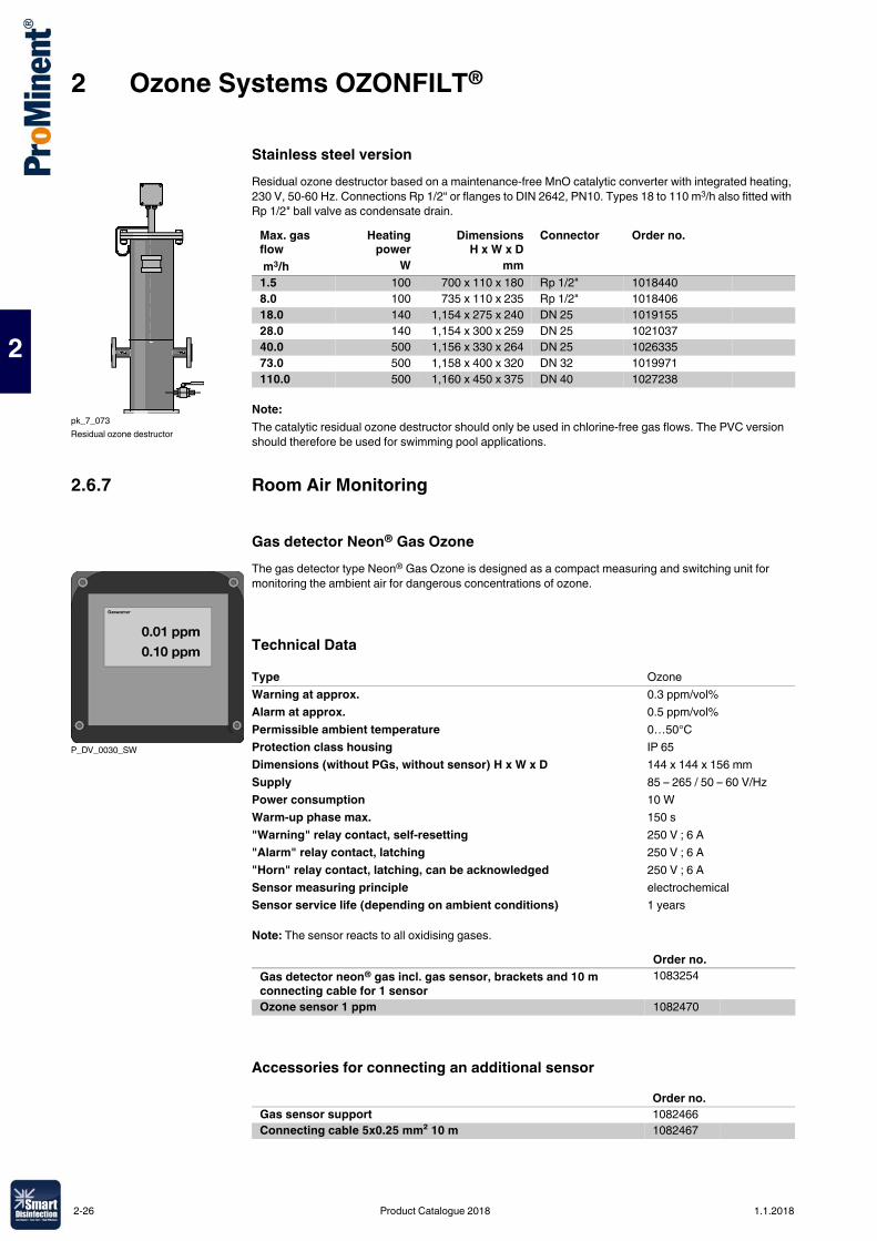
2 Ozone Systems OZONFILT®
2
Stainless steel versionResidual ozone destructor based on a maintenance-free MnO catalytic converter with integrated heating, 230 V, 50-60 Hz. Connections Rp 1/2“ or flanges to DIN 2642, PN10. Types 18 to 110 m3/h also fitted with Rp 1/2" ball valve as condensate drain.
Note:The catalytic residual ozone destructor should only be used in chlorine-free gas flows. The PVC version should therefore be used for swimming pool applications.
2.6.7 Room Air Monitoring
Gas detector Neon® Gas OzoneThe gas detector type Neon® Gas Ozone is designed as a compact measuring and switching unit for monitoring the ambient air for dangerous concentrations of ozone.
Technical Data
Note: The sensor reacts to all oxidising gases.
Accessories for connecting an additional sensor
pk_7_073Residual ozone destructor
Max. gas flow
Heatingpower
DimensionsH x W x D
Connector Order no.
m3/h W mm1.5 100 700 x 110 x 180 Rp 1/2" 10184408.0 100 735 x 110 x 235 Rp 1/2" 101840618.0 140 1,154 x 275 x 240 DN 25 101915528.0 140 1,154 x 300 x 259 DN 25 102103740.0 500 1,156 x 330 x 264 DN 25 102633573.0 500 1,158 x 400 x 320 DN 32 1019971110.0 500 1,160 x 450 x 375 DN 40 1027238
P_DV_0030_SW
Type OzoneWarning at approx. 0.3 ppm/vol%Alarm at approx. 0.5 ppm/vol%Permissible ambient temperature 0…50°CProtection class housing IP 65Dimensions (without PGs, without sensor) H x W x D 144 x 144 x 156 mmSupply 85 – 265 / 50 – 60 V/HzPower consumption 10 WWarm-up phase max. 150 s"Warning" relay contact, self-resetting 250 V ; 6 A"Alarm" relay contact, latching 250 V ; 6 A"Horn" relay contact, latching, can be acknowledged 250 V ; 6 ASensor measuring principle electrochemicalSensor service life (depending on ambient conditions) 1 years
Order no.Gas detector neon® gas incl. gas sensor, brackets and 10 m connecting cable for 1 sensor
1083254
Ozone sensor 1 ppm 1082470
Order no.Gas sensor support 1082466Connecting cable 5x0.25 mm² 10 m 1082467
2-26 Product Catalogue 2018 1.1.2018
2 Ozone Systems OZONFILT®
2
Flash light-hornCombined horn and red warning lamp. IP 33 housing made of impact-resistant grey ABS with a clear polycarbonate dome. Connected load: 230 V AC, 50 mA.
Gas tracing pumpHand operated, non-continuously working test tube pump for fast and accurate measurement of ozone gas. Complete with 10 no. ozone gas test tubes 0.05-5 ppm in carrying case.
Potassium iodide starch paperRoll with 4.8 m test strip for leak detection on pipelines carrying ozone gas.
2.6.8 Cooling Water Heat ExchangerA heat exchanger can be used as an alternative to the use of fresh water as cooling water. The cooling water is fed through the heat exchanger and ozone system in a circuit. The cooling water heat exchanger discharges the heat to the surroundings.
Technical Data� Single circuit system with tank open to the atmosphere� Air-cooled refrigeration unit� Integral evaporator� Tank with water level display and level switch with alarm contact� Microprocessor-controlled temperature controller with digital display� Integrated circulation pump� Manometer� Stainless steel housing� Installation material with 10 m hose for direct connection to the ozone system� Electrical contact inputs/outputs: On/Off contact, alarm contact, min. water level contact
Order no.Flash light-horn, red with continuous tone 1083160
Order no.Gas tracing pump 1025533
Order no.Potassium iodide starch paper 1025575
Order no. 1075498 1075499 1075501Refrigerant CFC-free R134a R134a R134aUseful cooling output at 20 °C/50 Hz kW 2.1 2.1 3.0Working range °C +10/+30 +10/+30 +10/+30Ambient temperature °C 10 – 55 10 – 55 10 – 55Pump Type Speck,
LNY-2841Speck, LNY-2841
Speck, LNY-2841
Pump capacity at 2 bar l/min 3.4 3.4 3.4Water connectors Inch 6 x 4 12 x 9 12 x 9Power consumption kW 1.9 1.9 1.9Mains connection V/Hz 230/50 – 60 230/50 – 60 230/50 – 60Degree of protection IP 44 44 44Weight kg 63 63 83Outside dimensions (W x D x H) mm 510x770x500 510x770x500 510x770x500
Suitable for type Order no.Cooling water heat exchanger OZVa 1 – 7 1075498
OZMa 1 – 2 A, OZMa 1 – 2 O 1075499OZMa 3 A, OZMa 3 O 1075501
1.1.2018 Product Catalogue 2018 2-27
2 Ozone Systems OZONFILT®
2
2.6.9 Personal Protection AccessoriesGas maskOzone-resistant, full-face respiratory protective mask with panoramic window shield to EN 136 Class 3. Medium size with EN 148-1 threaded pipe connection. Complete with combination filter NO-P3 and carrying case.
Warning labelWarning label in accordance with the “Guidelines for the use of ozone for water treatment” ZH 1/474, issued by the central office of the industrial safety associations. Version supplied as a combined adhesive label with markings as follows: warning sign, ozone plant room indication and prohibited activity signs.
Emergency stop switchFor installation near the door of the ozone plant room. IP 65 PVC enclosure.
2.6.10 Overvoltage ProtectionOvervoltage protection for OZONFILT® systems operated at 230 V 50-60 Hz.The external overvoltage protection is intended for the operating case where the device internal protection is insufficient for surge voltages of 1 kV between the conductors and of 2 kV to earth. To protect the system when the supply mains is prone to power transients an overvoltage trip can be fitted as a low protection surge arrestor to significantly increase the stability of the ozone systems.Whether the low protection surge arrestor requires further measures such as medium and main protection can only be determined by thorough investigation of the voltage behaviour on site.
2.6.11 Replacement Plug-in Insert After Tripping
Order no.Gas mask 1025574
Order no.Warning label 740921
Order no.Emergency stop switch 700560
Order no.Fine protection PT 2-DE IS 230 IAC 733010
Order no.Replacement plug-in insert PT 2-DE / S 230 / AC - ST 733011
2-28 Product Catalogue 2018 1.1.2018
3 Bello Zon® Chlorine Dioxide Systems
3
3.0.1Product Catalogue 2018
Chlorine dioxide is an exceptionally reactive gas, which is not stored due to its instability but rather must only be manufactured to meet requirements at its place of use in special systems.Chlorine dioxide has a number of advantages over chlorine, which is predominantly used in the disinfection of water. Thus for instance, the disinfection effect does not reduce with increasing pH-value, as is the case with chlorine, rather it increases slightly. Chlorine dioxide remains stable in pipework systems over long periods of time and provides microbiological protection of the water for many hours and up to several days. Ammonia or ammonium, which cause considerable chlorine loss, do not react with chlorine dioxide so that the metered chlorine dioxide remains fully available for disinfection purposes. Chlorophenols, strongly smelling compounds, which result from the chlorination of water etc., are not formed with chlorine dioxide. Trihalogenmethanes (THMs), a substance class, which, like their main representative, chloroform, is suspected of being carcinogens, result from the reaction of chlorine with dissolved matter naturally found in water (humic acids, fulvic acids, etc.). If chlorine dioxide is used as an alternative disinfectant these substances are not produced.
Advantages of chlorine dioxide:� Disinfectant effect regardless of the pH value.� Excellent depositing effect, thanks to long-term stability in the pipework.� Degradation of biofilms in pipework and tanks, thus reliable protection of entire water systems against
legionella attack.� No reaction with ammonia or ammonium.� No formation of chlorophenols and other strongly smelling compounds that can be produced during
water chlorination.� No formation of trihalomethanes (THM) or other chlorinated hydrocarbons, no increase in AOX values.
3.1.1 Chlorine Dioxide ApplicationsWith every new project, our engineers draw on experience that we have accumulated since 1976 in the following applications:
Municipal potable water and waste water companies� Disinfection of potable water� Disinfection of waste water
Hotels, hospitals, care homes, sports centres etc.� Combating legionella in cold and hot water systems� Water disinfection in the cooling towers of air conditioning systems� Disinfection of swimming pool filters
Food and beverage industry� Disinfection of product and raw water� Bottle cleaning, rinsers and pasteurisers� Cold-sterile bottling systems� Disinfectant in CIP systems� Water vapour treatment (condensation) in the milk industry� Water treatment for fruit, vegetable, seafood, fish and poultry processing
Market gardening
� Disinfection of irrigation water in plant cultivation
Industry� Cooling water treatment� Combating legionella in cooling water circuits� Disinfection of process water� Removal of odorous substances in air scrubbers� Slime control in the paper industry
3.1 Chlorine Dioxide in Water Treatment
1.1.2018 Product Catalogue 2018 3-1
3 Bello Zon® Chlorine Dioxide Systems
3
3.1.2 Bello Zon® System TechnologyBello Zon® chlorine dioxide generation and metering systems use the chlorite/acid process. These systems generate a chlorine-free chlorine dioxide solution through the reaction of sodium chlorite solution with hydrochloric acid.Decades of experience with Bello Zon® chlorine dioxide systems have shown that using the selected process parameters can achieve an excellent output of up to 99% (relative to the stoichiometric ratio).In most applications, metering is proportional to the flow, i.e. the flow depends on the signal from an inductive or contact flow meter or is performed in parallel to a feed pump.In circulation systems, such as bottle washing machines, cooling circuits, etc., where a chlorine dioxide loss need only be made good, the addition can also be controlled based on a measurement of chlorine dioxide.
Features � Precise and reproducible chlorine dioxide production, thanks to the use of calibratable metering pumps
for the starting chemicals.� Convenient easy operation, thanks to microprocessor control with display of all relevant operating
parameters and error messages in plain text.� Display of the current production quantity as well as the flow rate of the connected flow meters with CDV
and CDK.� Integrated measurement of ClO2 and chlorite plus control of ClO2 with CDV and CDK.� Highest safety level provided as standard, thanks to construction and operation in accordance with
DVGW specifications W 224 and W 624.
Bello Zon® CDLCompact dimensions and maximum cost-effectiveness - chlorine dioxide system for one or more points of injection.0 – 120 g/h capacity with storage of up to 60 g of chlorine dioxide for peak metering. Max. flow rate at 0.2 ppm ClO2 metering capacity of 600 m3/h
Bello Zon® CDEBello Zon® CDEb is winning over customers, thanks to its ultra-simple operation and clearly laid out construction.5-200 g/h chlorine dioxide. Max. flow at 0.2 ppm ClO2 metering is 1,000 m3/h
Bello Zon® CDVBello Zon® CDVc is the convenient system for the treatment of average to large volumes of water.1 – 2,000 g/h chlorine dioxide. Max. flow at 0.2 ppm ClO2 metering is 10,000 m3/h
Bello Zon® CDKBello Zon® CDKc is a deluxe system, persuading customers with its safe handling of chemicals.8 – 12,000 g/h chlorine dioxide. Max. flow rate at 0.2 ppm ClO2 metering is 60,000 m3/h
ProMinent provides all the advice needed for the safe operation of a chlorine dioxide system:� Evaluation of the situation on site by trained, expert field sales staff.� Interpretation of water analysis.� Project planning of the system.� Commissioning and system maintenance by our trained service technicians.
3-2 Product Catalogue 2018 1.1.2018
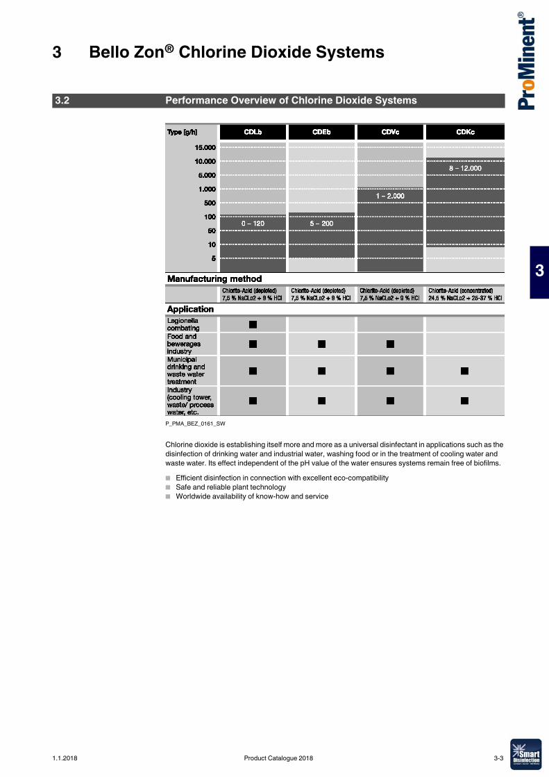
3 Bello Zon® Chlorine Dioxide Systems
3
P_PMA_BEZ_0161_SW
Chlorine dioxide is establishing itself more and more as a universal disinfectant in applications such as the disinfection of drinking water and industrial water, washing food or in the treatment of cooling water and waste water. Its effect independent of the pH value of the water ensures systems remain free of biofilms.� Efficient disinfection in connection with excellent eco-compatibility� Safe and reliable plant technology� Worldwide availability of know-how and service
3.2 Performance Overview of Chlorine Dioxide Systems
1.1.2018 Product Catalogue 2018 3-3
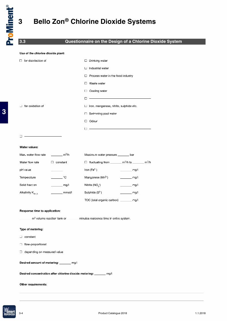
3 Bello Zon® Chlorine Dioxide Systems
3
3.3 Questionnaire on the Design of a Chlorine Dioxide System
3-4 Product Catalogue 2018 1.1.2018
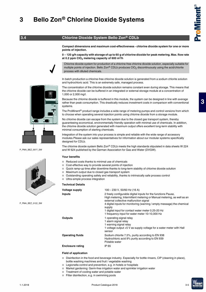
3 Bello Zon® Chlorine Dioxide Systems
3
Compact dimensions and maximum cost-effectiveness - chlorine dioxide system for one or more points of injection.0 – 120 g/h capacity with storage of up to 60 g of chlorine dioxide for peak metering. Max. flow rate at 0.2 ppm ClO2 metering capacity of 600 m3/h
In batch production a chlorine-free chlorine dioxide solution is generated from a sodium chlorite solution and hydrochloric acid. This is an extremely safe, managed process. The concentration of the chlorine dioxide solution remains constant even during storage. This means that the chlorine dioxide can be buffered in an integrated or external storage module at a concentration of 1,000 or 2,000 mg/l. Because the chlorine dioxide is buffered in this module, the system can be designed in line with average rather than peak consumption. This drastically reduces investment costs in comparison with conventional systems. The ProMinent® product range includes a wide range of metering pumps and control versions from which to choose when operating several injection points using chlorine dioxide from a storage module.No chlorine dioxide can escape from the system due to the closed gas transport system, thereby guaranteeing economical, environmentally friendly operation with minimal use of chemicals. In addition, the chlorine dioxide solution generated with maximum output offers excellent long-term stability with minimal consumption of starting chemicals.Integration of the system into your process is simple and reliable with the wide range of accessory modules.Please ask our sales representatives for information about our modular systems specifically designed for CDLb. The chlorine dioxide system Bello Zon® CDLb meets the high standards stipulated in data sheets W 224 and W 624 published by the German Association for Gas and Water (DVGW).
Your benefits� Reduced costs thanks to minimal use of chemicals� Cost-effective way to provide several points of injection � Quick ramp-up time after downtime thanks to long-term stability of chlorine dioxide solution� Maximum output due to closed gas transport system� Outstanding operating safety and reliability, thanks to intrinsically safe process control� Ultra-simple process integration Technical Details
Field of application� Disinfection in the food and beverage industry. Especially for bottle rinsers, CIP (cleaning in place),
bottle washing machines and fruit / vegetable washing� Legionella control and prevention, e.g. in hotels or hospitals� Market gardening: Germ-free irrigation water and sprinkler irrigation water� Treatment of cooling water and potable water � Filter disinfection, e.g. in swimming pools
3.4 Chlorine Dioxide System Bello Zon® CDLb
Chlorine dioxide system for production of a chlorine-free chlorine dioxide solution, especially suitable for multiple points of injection. Bello Zon® CDLb produces ClO2 discontinuously using the acid/chlorite process with diluted chemicals.
P_PMA_BEZ_0077_SW
P_PMA_BEZ_0122_SW
Voltage supply 100 – 230 V, 50/60 Hz (16 A)Inputs 2 freely configurable digital inputs for the functions Pause,
High metering, Intermittent metering or Manual metering, as well as an external collective malfunction signal4 digital inputs for monitoring (warning / empty message) the chemical supply1 digital input for contact water meter 0.25-20 Hz1 frequency input for water meter 10-10,000 Hz
Outputs 1 operating signal relay1 alarm signal relay1 warning signal relay1 voltage output +5 V as supply voltage for a water meter with Hall sensor
Operating fluids Sodium chlorite 7.5%, purity according to EN 938Hydrochloric acid 9% purity according to EN 939Potable water
Enclosure rating IP 65
1.1.2018 Product Catalogue 2018 3-5
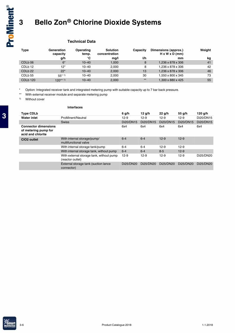
3 Bello Zon® Chlorine Dioxide Systems
3
Technical Data
Interfaces
Type Generationcapacity
Operatingtemp.
Solutionconcentration
Capacity Dimensions (approx.)H x W x D (mm)
Weight
g/h °C mg/l l/h mm kgCDLb 06 6* 10–40 1,000 8 1,236 x 878 x 306 41CDLb 12 12* 10–40 2,000 8 1,236 x 878 x 306 42CDLb 22 22* 10–40 2,000 13 1,236 x 878 x 306 46CDLb 55 55* 1) 10–40 2,000 30 1,550 x 800 x 345 73CDLb 120 120** 1) 10–40 2,000 ** 1,300 x 880 x 425 55
* Option: Integrated receiver tank and integrated metering pump with suitable capacity up to 7 bar back pressure.** With external receiver module and separate metering pump1) Without cover
Type CDLb 6 g/h 12 g/h 22 g/h 55 g/h 120 g/hWater inlet ProMinent/Neutral 12-9 12-9 12-9 12-9 Di20/DN15
Swiss Di20/DN15 Di20/DN15 Di20/DN15 Di20/DN15 Di20/DN15Connector dimensions of metering pump for acid and chlorite
6x4 6x4 6x4 6x4 6x4
ClO2 outlet With internal storage/pump/multifunctional valve
6-4 6-4 12-9 12-9
With internal storage tank/pump 6-4 6-4 12-9 12-9With internal storage tank, without pump 6-4 6-4 8-5 12-9With external storage tank, without pump (reactor outlet)
12-9 12-9 12-9 12-9 Di25/DN20
External storage tank (suction lance connector)
Di25/DN20 Di25/DN20 Di25/DN20 Di25/DN20 Di25/DN20
3-6 Product Catalogue 2018 1.1.2018
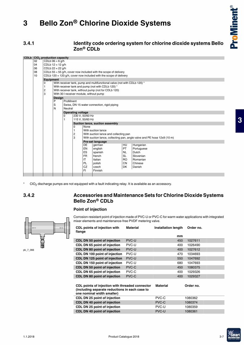
3 Bello Zon® Chlorine Dioxide Systems
3
3.4.1 Identity code ordering system for chlorine dioxide systems Bello Zon® CDLb
3.4.2 Accessories and Maintenance Sets for Chlorine Dioxide Systems Bello Zon® CDLb Point of injectionCorrosion-resistant point of injection made of PVC-U or PVC-C for warm water applications with integrated mixer elements and maintenance-free PVDF metering valve.
CDLb ClO2 production capacity02 CDLb 06 = 6 g/h04 CDLb 12 = 12 g/h06 CDLb 22 = 22 g/h08 CDLb 55 = 55 g/h, cover now included with the scope of delivery10 CDLb 120 = 120 g/h, cover now included with the scope of delivery
Equipment0 With receiver tank, pump and multifunctional valve (not with CDLb 120) *1 With receiver tank and pump (not with CDLb 120) *2 With receiver tank, without pump (not for CDLb 120)3 With 30 l receiver module, without pump
DesignP ProMinentS Swiss, DN 15 water connection, rigid pipingN Neutral
Operating voltage0 230 V, 50/60 Hz1 115 V, 50/60 Hz
Suction lance, suction assembly0 None1 With suction lance2 With suction lance and collecting pan3 With suction lance, collecting pan, angle valve and PE hose 12x9 (10 m)
Pre-set languageDE german HU HungarianEN english PT PortugueseES spanish NL DutchFR french SL SlovenianIT italian RO RomanianPL polish CN ChineseCZ czech DK DanishFI Finnish
* ClO2 discharge pumps are not equipped with a fault indicating relay. It is available as an accessory.
pk_7_066
CDL points of injection with flange
Material Installation length Order no.
mmCDL DN 50 point of injection PVC-U 450 1027611CDL DN 65 point of injection PVC-U 400 1026490CDL DN 80 point of injection PVC-U 400 1027612CDL DN 100 point of injection PVC-U 470 1034693CDL DN 125 point of injection PVC-U 550 1047692CDL DN 150 point of injection PVC-U 680 1047693CDL DN 50 point of injection PVC-C 450 1080375CDL DN 65 point of injection PVC-C 400 1029326CDL DN 80 point of injection PVC-C 400 1029327
CDL points of injection with threaded connector (including separate reductions in each case to one nominal width smaller)
Material Order no.
CDL DN 25 point of injection PVC-C 1080362CDL DN 40 point of injection PVC-C 1080374CDL DN 25 point of injection PVC-U 1080359CDL DN 40 point of injection PVC-U 1080361
1.1.2018 Product Catalogue 2018 3-7
3 Bello Zon® Chlorine Dioxide Systems
3
Temperature/pressure resistance – metering station CDL
Back pressure valve and angle valveBack pressure valve type MFV with wall bracket and 6 x 4 mm hose connection is ideal for fitting in the chlorine dioxide metering line. Angle valve for the transition from the customer's pipeline to the 12x9 hose connector on the CDLb.
Fault indicating relay for the ClO2 pumpFault indicating relay retrofit kit for the ClO2 discharge pump
Hood for CDLb
Safety collecting pan for chemical containersCollecting pan with two separate compartments - 1 No. 25 l Bello Zon® acid and 1 No. 10 l Bello Zon® chlorite chemical container.Dimensions (HxWxD): 290 x 700 x 350 mm
Safety collecting pan for chemical tanks (CDLb)Collecting pan for a 25 l Bello Zon® acid or Bello Zon® chlorite chemical canister.Dimensions (HxWxD): 266 x 400 x 500 mm
Service kits for CDLaThe kits contain all parts subject to wear and tear that need to be replaced at regular service intervals. The 1-year kit should be used every year and the 3-year kit in addition every 3 years.
Water temperature (°C) Maximum permissible operating pressure (bar)PVC-U PVC-C
40 12 1250 7 9.560 4.5 7.570 – 580 – 3
Order no.MFV pressure relief valve with wall mounting bracket 1027652Angle valve (support insert 12/9 stainless steel) DN15 G 1/2" brass 1046350
Order no.Relay 3-pin 1029309
Order no.Hood for CDLb 55 PE black 1045889Hood for CDLb 120 PE black 1045890
Order no.Safety collecting pan CDLa 1026744
Order no.Safety collecting pan CDLb 791726
Order no.1-year service kit for pressure relief valve 1029442
3-8 Product Catalogue 2018 1.1.2018
3 Bello Zon® Chlorine Dioxide Systems
3
For CDLa with ClO2 pump
For CDLa without ClO2 pump
Maintenance sets for Bello Zon® CDLb
For CDLb with storage tank, pump and back pressure valve
For CDLb with receiver tank and pump
Type Order no.Annual maintenance kit, 230 V CDL 5 10272633-yearly maintenance set, 230 V CDL 5 1049659Annual maintenance kit, 230 V CDL 10 10315493-yearly maintenance set, 230 V CDL 10 1049665Annual maintenance kit, 115 V CDLa 5 10801083-yearly maintenance set, 115 V CDLa 5 1049657Annual maintenance kit, 115 V CDLa 10 10801103-yearly maintenance set, 115 V CDLa 10 1049663
Type Order no.Annual maintenance kit, 230 V CDL5 10428293-yearly maintenance set, 230 V CDL5 1049660Annual maintenance kit, 230 V CDL10 10428303-yearly maintenance set, 230 V CDL10 1049666Annual maintenance kit, 115 V CDLa 5 10801073-yearly maintenance set, 115 V CDLa 5 1049658Annual maintenance kit, 115 V CDLa 10 10801093-yearly maintenance set, 115 V CDLa 10 1049664
Type Order no.Annual maintenance kit, 230 V CDLb 06, CDLb 12 1044484Annual maintenance kit, 230 V CDLb 22 1044501Annual maintenance kit, 230 V CDLb 55 1044509Annual maintenance kit, 115 V CDLb 06, CDLb 12 1079198Annual maintenance kit, 115 V CDLb 22 1079202Annual maintenance kit, 115 V CDLb 55 10792063-yearly maintenance set, 230 V CDLb 06, CDLb 12 10444943-yearly maintenance set, 230 V CDLb 22 10445023-yearly maintenance set, 230 V CDLb 55 10445103-yearly maintenance set, 115 V CDLb 06, CDLb 12 10452123-yearly maintenance set, 115 V CDLb 22 10452163-yearly maintenance set, 115 V CDLb 55 1045220
Type Order no.Annual maintenance kit, 230 V CDLb 06, CDLb 12 1044495Annual maintenance kit, 230 V CDLb 22 1044503Annual maintenance kit, 230 V CDLb 55 1044511Annual maintenance kit, 115 V CDLb 06, CDLb 12 1079199Annual maintenance kit, 115 V CDLb 22 1079203Annual maintenance kit, 115 V CDLb 55 10792073-yearly maintenance set, 230 V CDLb 06, CDLb 12 10444963-yearly maintenance set, 230 V CDLb 22 10445043-yearly maintenance set, 230 V CDLb 55 10445123-yearly maintenance set, 115 V CDLb 06, CDLb 12 10452133-yearly maintenance set, 115 V CDLb 22 10452173-yearly maintenance set, 115 V CDLb 55 1045221
1.1.2018 Product Catalogue 2018 3-9
3 Bello Zon® Chlorine Dioxide Systems
3
For CDLb with receiver tank without pump
For CDLb with 30 l receiver module without pump
Type Order no.Annual maintenance kit, 230 V CDLb 06, CDLb 12 1044497Annual maintenance kit, 230 V CDLb 22 1044505Annual maintenance kit, 230 V CDLb 55 1044513Annual maintenance kit, 115 V CDLb 06, CDLb 12 1079200Annual maintenance kit, 115 V CDLb 22 1079204Annual maintenance kit, 115 V CDLb 55 10792083-yearly maintenance set, 230 V CDLb 06, CDLb 12 10444983-yearly maintenance set, 230 V CDLb 22 10445063-yearly maintenance set, 230 V CDLb 55 10445143-yearly maintenance set, 115 V CDLb 06, CDLb 12 10452143-yearly maintenance set, 115 V CDLb 22 10452183-yearly maintenance set, 115 V CDLb 55 1045222
Type Order no.Annual maintenance kit, 230 V CDLb 06, CDLb 12 1044499Annual maintenance kit, 230 V CDLb 22 1044507Annual maintenance kit, 230 V CDLb 55 1044515Annual maintenance kit, 230 V CDLb 120 1044517Annual maintenance kit, 115 V CDLb 06, CDLb 12 1079201Annual maintenance kit, 115 V CDLb 22 1079205Annual maintenance kit, 115 V CDLb 55 10792093-yearly maintenance set, 230 V CDLb 06, CDLb 12 10445003-yearly maintenance set, 230 V CDLb 22 10445083-yearly maintenance set, 230 V CDLb 55 10445163-yearly maintenance set, 230 V CDLb 120 10445193-yearly maintenance set, 115 V CDLb 06, CDLb 12 10452153-yearly maintenance set, 115 V CDLb 22 10452193-yearly maintenance set, 115 V CDLb 55 10452233-yearly maintenance set, 115 V CDLb 120 1044519
3-10 Product Catalogue 2018 1.1.2018
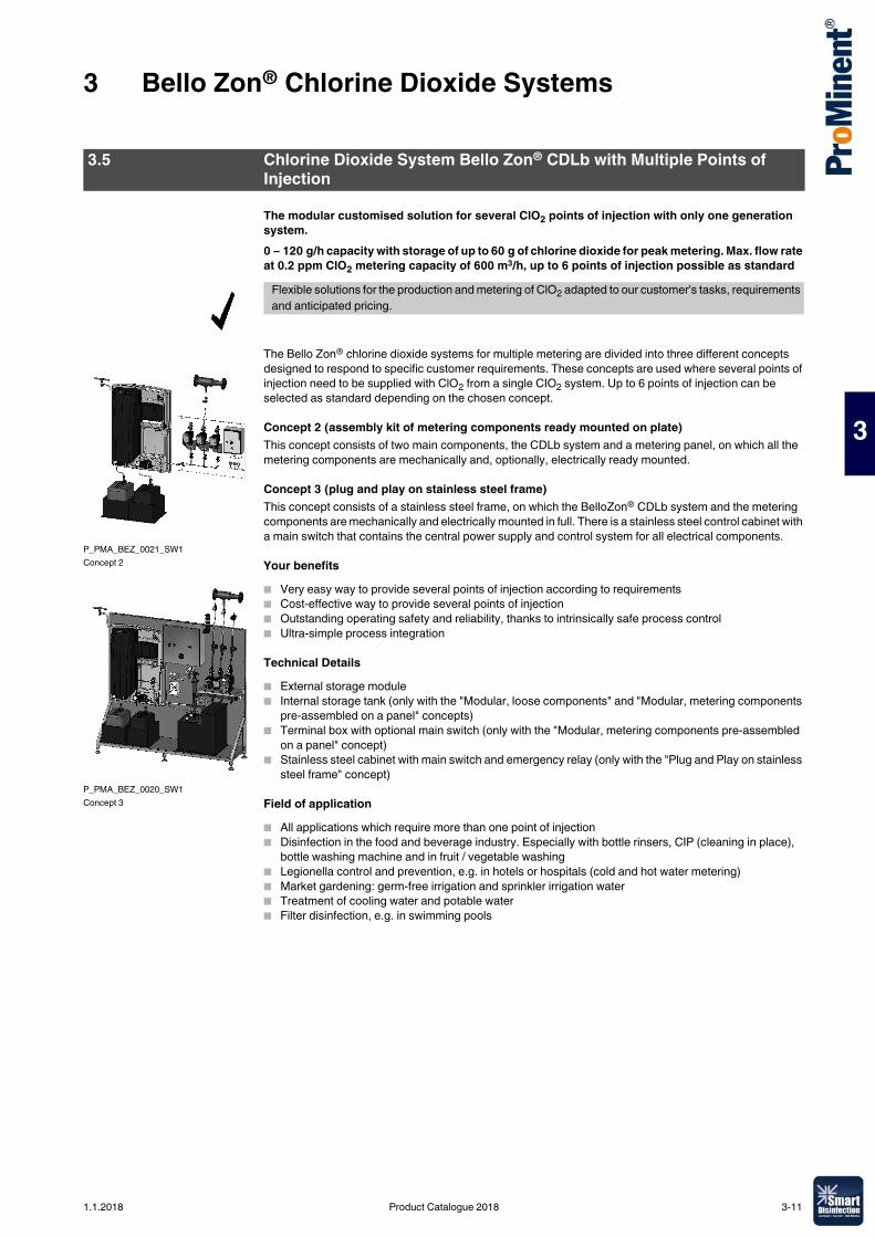
3 Bello Zon® Chlorine Dioxide Systems
3
The modular customised solution for several ClO2 points of injection with only one generation system.0 – 120 g/h capacity with storage of up to 60 g of chlorine dioxide for peak metering. Max. flow rate at 0.2 ppm ClO2 metering capacity of 600 m3/h, up to 6 points of injection possible as standard
The Bello Zon® chlorine dioxide systems for multiple metering are divided into three different concepts designed to respond to specific customer requirements. These concepts are used where several points of injection need to be supplied with ClO2 from a single CIO2 system. Up to 6 points of injection can be selected as standard depending on the chosen concept.
Concept 2 (assembly kit of metering components ready mounted on plate)This concept consists of two main components, the CDLb system and a metering panel, on which all the metering components are mechanically and, optionally, electrically ready mounted.
Concept 3 (plug and play on stainless steel frame)This concept consists of a stainless steel frame, on which the BelloZon® CDLb system and the metering components are mechanically and electrically mounted in full. There is a stainless steel control cabinet with a main switch that contains the central power supply and control system for all electrical components.
Your benefits� Very easy way to provide several points of injection according to requirements� Cost-effective way to provide several points of injection � Outstanding operating safety and reliability, thanks to intrinsically safe process control� Ultra-simple process integration
Technical Details� External storage module� Internal storage tank (only with the "Modular, loose components" and "Modular, metering components
pre-assembled on a panel" concepts)� Terminal box with optional main switch (only with the "Modular, metering components pre-assembled
on a panel" concept)� Stainless steel cabinet with main switch and emergency relay (only with the "Plug and Play on stainless
steel frame" concept)
Field of application� All applications which require more than one point of injection� Disinfection in the food and beverage industry. Especially with bottle rinsers, CIP (cleaning in place),
bottle washing machine and in fruit / vegetable washing� Legionella control and prevention, e.g. in hotels or hospitals (cold and hot water metering)� Market gardening: germ-free irrigation and sprinkler irrigation water� Treatment of cooling water and potable water � Filter disinfection, e.g. in swimming pools
3.5 Chlorine Dioxide System Bello Zon® CDLb with Multiple Points of Injection
Flexible solutions for the production and metering of ClO2 adapted to our customer's tasks, requirements and anticipated pricing.
P_PMA_BEZ_0021_SW1Concept 2
P_PMA_BEZ_0020_SW1Concept 3
1.1.2018 Product Catalogue 2018 3-11
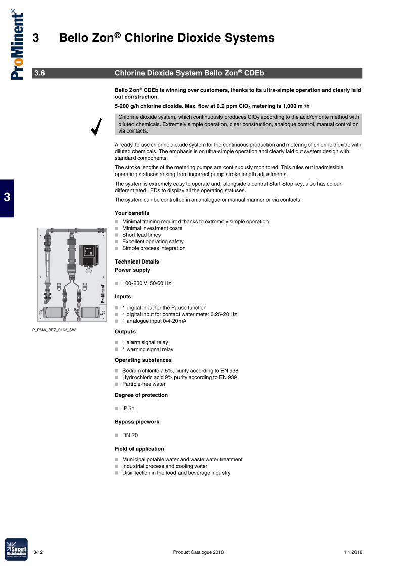
3 Bello Zon® Chlorine Dioxide Systems
3
Bello Zon® CDEb is winning over customers, thanks to its ultra-simple operation and clearly laid out construction.5-200 g/h chlorine dioxide. Max. flow at 0.2 ppm ClO2 metering is 1,000 m3/h
A ready-to-use chlorine dioxide system for the continuous production and metering of chlorine dioxide with diluted chemicals. The emphasis is on ultra-simple operation and clearly laid out system design with standard components. The stroke lengths of the metering pumps are continuously monitored. This rules out inadmissible operating statuses arising from incorrect pump stroke length adjustments.The system is extremely easy to operate and, alongside a central Start-Stop key, also has colour-differentiated LEDs to display all the operating statuses. The system can be controlled in an analogue or manual manner or via contacts
Your benefits� Minimal training required thanks to extremely simple operation � Minimal investment costs� Short lead times� Excellent operating safety � Simple process integration
Technical DetailsPower supply
� 100-230 V, 50/60 Hz
Inputs� 1 digital input for the Pause function� 1 digital input for contact water meter 0.25-20 Hz� 1 analogue input 0/4-20mAOutputs� 1 alarm signal relay� 1 warning signal relayOperating substances� Sodium chlorite 7.5%, purity according to EN 938� Hydrochloric acid 9% purity according to EN 939� Particle-free waterDegree of protection
� IP 54
Bypass pipework
� DN 20
Field of application� Municipal potable water and waste water treatment � Industrial process and cooling water� Disinfection in the food and beverage industry
3.6 Chlorine Dioxide System Bello Zon® CDEb
Chlorine dioxide system, which continuously produces ClO2 according to the acid/chlorite method with diluted chemicals. Extremely simple operation, clear construction, analogue control, manual control or via contacts.
P_PMA_BEZ_0163_SW
3-12 Product Catalogue 2018 1.1.2018
3 Bello Zon® Chlorine Dioxide Systems
3
Technical Data
Subject to technical and design changes
Scope of supply:Bello Zon® CDEb systems are supplied connection-ready on a wall panel. Connection to the site bypass line is via DN 20 PVC threaded connectors with straight solvent unions. Order suction lances for the chemical pumps, safety collecting pans for the chemical drums and other accessories, like flushing equipment with a vacuum relief valve separately.
Type Chlorine dioxidecapacity*
Max. operating pressure **
Operatingtemp.
Connector size, chlorite and acid metering pumps
Dimensions H x W x D
Dimensions ofthe bypassconnector
Weight
min.-max./hour
min./day
g/h g/d °C mm DN kgCDEb 30 5–30 10 7 / 8 ** 15–40 6x4 958 x 700 x 250 20 23CDEb 75 10–75 20 7 / 8 ** 15–40 6x4 958 x 700 x 250 20 24CDEb 200 20–200 40 7 / 8 ** 15–40 8x5 958 x 700 x 250 20 27
* The metering figures relate to 5 bar back pressure and an ambient temperature of 20 °C. The minimum capacity/per hour is based on the fact that when the system is operating at below 10 % of the nominal capacity, continuous metering is no longer possible, due to the then low pumping frequency of the metering pumps. Where systems are operating continuously, change the reactor content at least 2 x daily. Do not operate at below the specific minimal output/day.
** 8 bar at maximum 35 °C ambient temperature
Type Order no.CDEb 30 1079438CDEb 75 1079439CDEb 200 1079440
1.1.2018 Product Catalogue 2018 3-13
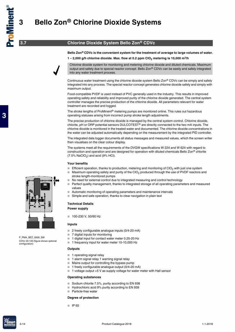
3 Bello Zon® Chlorine Dioxide Systems
3
Bello Zon® CDVc is the convenient system for the treatment of average to large volumes of water.1 – 2,000 g/h chlorine dioxide. Max. flow at 0.2 ppm ClO2 metering is 10,000 m3/h
Continuous water treatment using the chlorine dioxide system Bello Zon® CDVc can be simply and safely integrated into any process. The special reactor concept generates chlorine dioxide safely and simply with maximum output.Food-compatible PVDF is used instead of PVC generally used in the industry. This results in improved operating safety and reliability and improved purity of the chlorine dioxide generated. The central system controller manages the precise production of the chlorine dioxide. All parameters relevant for water treatment are recorded and logged.The stroke lengths of ProMinent® metering pumps are monitored online. This rules out hazardous operating statuses arising from incorrect pump stroke length adjustments.The precise production of chlorine dioxide is managed by the central system control. Chlorine dioxide, chlorite, pH or ORP potential sensors DULCOTEST® are directly connected to the two mA inputs. The chlorine dioxide is monitored in the treated water and documented. The chlorine dioxide concentrations in the water can be adjusted automatically depending on the measurement by the integrated PID controller.The integrated data logger documents all status messages and measured values, which the screen writer then visualises on the clear colour display.The systems meet all the requirements of the DVGW specifications W 224 and W 624 with regard to construction and operation and are designed for operation with diluted chemicals Bello Zon® chlorite (7.5% NaClO2) and acid (9% HCl).
Your benefits� Efficient operation, thanks to production, metering and monitoring of ClO2 with just one system� Maximum operating safety and purity of the CIO2 produced through the use of PVDF reactors and
stroke length-monitored pumps � No need for external control due to integrated measuring and control technology� Perfect quality management, thanks to integrated storage of all operating parameters and measured
values� Automatic monitoring of operating parameters and maintenance intervals� Simple and safe operation, thanks to clear navigation in plain text
Technical DetailsPower supply
� 100-230 V, 50/60 Hz
Inputs� 2 freely configurable analogue inputs (0/4-20 mA) � 7 digital inputs for monitoring� 1 digital input for contact water meter 0.25-20 Hz� 1 frequency input for water meter 10-10,000 HzOutputs� 1 operating signal relay� 1 alarm signal relay 1 warning signal relay� Mains output for controlling the bypass pump� 1 freely configurable analogue output (0/4-20 mA)� 1 voltage output +5 V as supply voltage for water meter with Hall sensorOperating substances� Sodium chlorite 7.5%, purity according to EN 938� Hydrochloric acid 9% purity according to EN 939� Particle-free waterDegree of protection
� IP 65
3.7 Chlorine Dioxide System Bello Zon® CDVc
Chlorine dioxide system for monitoring and metering chlorine dioxide and diluted chemicals. Maximum output and safety due to special reactor concept. Bello Zon® CDVc can be easily and safely integrated into any water treatment process.
P_PMA_BEZ_0009_SWCDVc 20-120 (figure shows optional configuration)
3-14 Product Catalogue 2018 1.1.2018
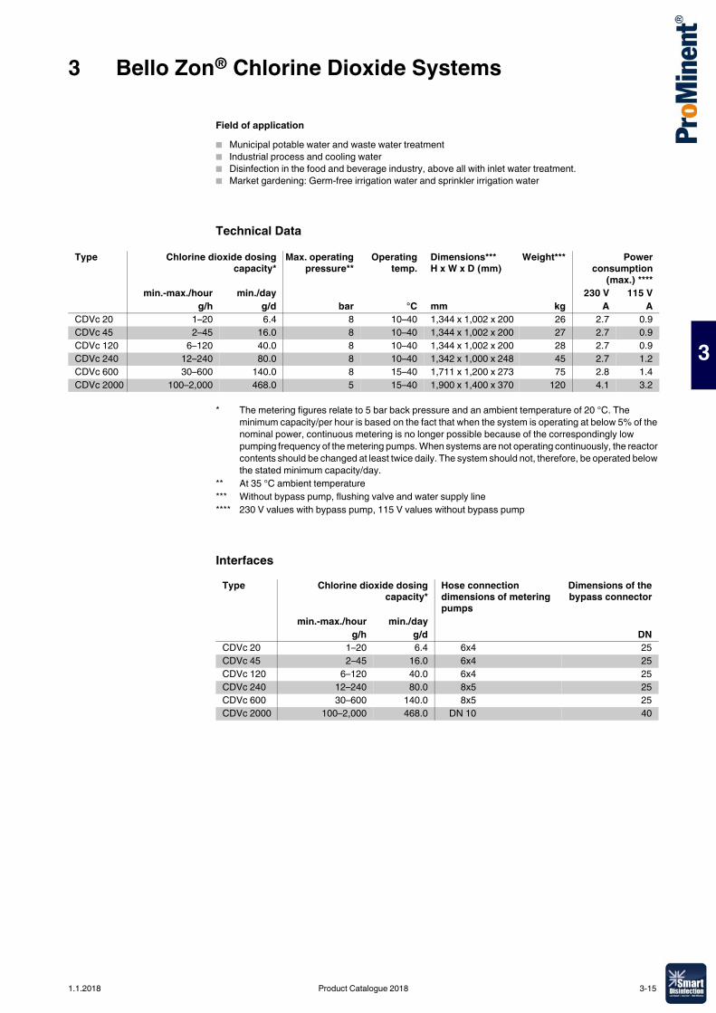
3 Bello Zon® Chlorine Dioxide Systems
3
Field of application� Municipal potable water and waste water treatment� Industrial process and cooling water� Disinfection in the food and beverage industry, above all with inlet water treatment.� Market gardening: Germ-free irrigation water and sprinkler irrigation water
Technical Data
Interfaces
Type Chlorine dioxide dosingcapacity*
Max. operatingpressure**
Operatingtemp.
Dimensions*** H x W x D (mm)
Weight*** Powerconsumption
(max.) ****min.-max./hour min./day 230 V 115 V
g/h g/d bar °C mm kg A ACDVc 20 1–20 6.4 8 10–40 1,344 x 1,002 x 200 26 2.7 0.9CDVc 45 2–45 16.0 8 10–40 1,344 x 1,002 x 200 27 2.7 0.9CDVc 120 6–120 40.0 8 10–40 1,344 x 1,002 x 200 28 2.7 0.9CDVc 240 12–240 80.0 8 10–40 1,342 x 1,000 x 248 45 2.7 1.2CDVc 600 30–600 140.0 8 15–40 1,711 x 1,200 x 273 75 2.8 1.4CDVc 2000 100–2,000 468.0 5 15–40 1,900 x 1,400 x 370 120 4.1 3.2
* The metering figures relate to 5 bar back pressure and an ambient temperature of 20 °C. The minimum capacity/per hour is based on the fact that when the system is operating at below 5% of the nominal power, continuous metering is no longer possible because of the correspondingly low pumping frequency of the metering pumps. When systems are not operating continuously, the reactor contents should be changed at least twice daily. The system should not, therefore, be operated below the stated minimum capacity/day.
** At 35 °C ambient temperature*** Without bypass pump, flushing valve and water supply line**** 230 V values with bypass pump, 115 V values without bypass pump
Type Chlorine dioxide dosingcapacity*
Hose connection dimensions of metering pumps
Dimensions of thebypass connector
min.-max./hour min./dayg/h g/d DN
CDVc 20 1–20 6.4 6x4 25CDVc 45 2–45 16.0 6x4 25CDVc 120 6–120 40.0 6x4 25CDVc 240 12–240 80.0 8x5 25CDVc 600 30–600 140.0 8x5 25CDVc 2000 100–2,000 468.0 DN 10 40
1.1.2018 Product Catalogue 2018 3-15
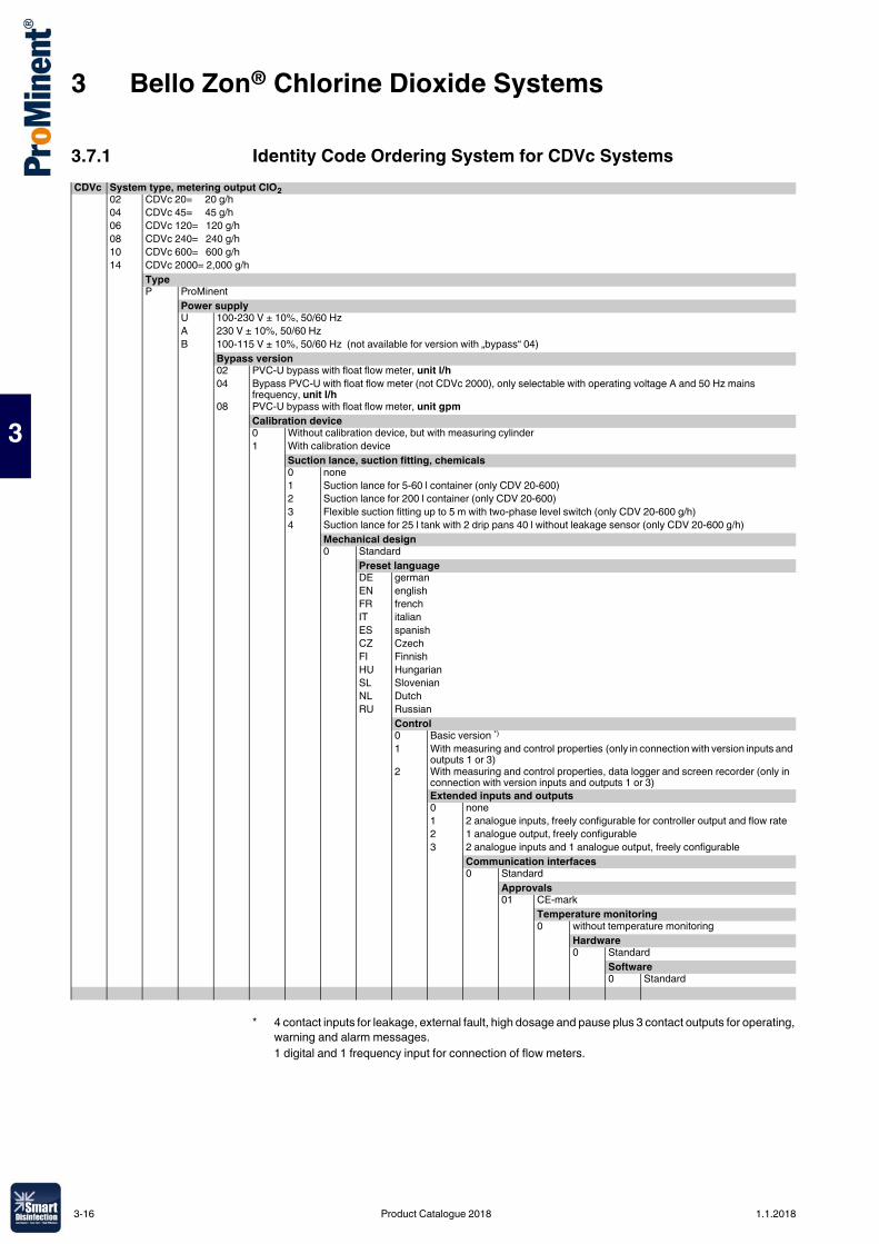
3 Bello Zon® Chlorine Dioxide Systems
3
3.7.1 Identity Code Ordering System for CDVc SystemsCDVc System type, metering output ClO2
02 CDVc 20= 20 g/h04 CDVc 45= 45 g/h06 CDVc 120= 120 g/h08 CDVc 240= 240 g/h10 CDVc 600= 600 g/h14 CDVc 2000= 2,000 g/h
TypeP ProMinent
Power supplyU 100-230 V ± 10%, 50/60 Hz A 230 V ± 10%, 50/60 Hz B 100-115 V ± 10%, 50/60 Hz (not available for version with „bypass“ 04)
Bypass version02 PVC-U bypass with float flow meter, unit l/h04 Bypass PVC-U with float flow meter (not CDVc 2000), only selectable with operating voltage A and 50 Hz mains
frequency, unit l/h08 PVC-U bypass with float flow meter, unit gpm
Calibration device0 Without calibration device, but with measuring cylinder1 With calibration device
Suction lance, suction fitting, chemicals0 none1 Suction lance for 5-60 l container (only CDV 20-600)2 Suction lance for 200 l container (only CDV 20-600)3 Flexible suction fitting up to 5 m with two-phase level switch (only CDV 20-600 g/h)4 Suction lance for 25 l tank with 2 drip pans 40 l without leakage sensor (only CDV 20-600 g/h)
Mechanical design0 Standard
Preset languageDE germanEN englishFR frenchIT italianES spanishCZ CzechFI FinnishHU HungarianSL SlovenianNL DutchRU Russian
Control0 Basic version *)
1 With measuring and control properties (only in connection with version inputs and outputs 1 or 3)
2 With measuring and control properties, data logger and screen recorder (only in connection with version inputs and outputs 1 or 3)Extended inputs and outputs0 none1 2 analogue inputs, freely configurable for controller output and flow rate2 1 analogue output, freely configurable3 2 analogue inputs and 1 analogue output, freely configurable
Communication interfaces0 Standard
Approvals01 CE-mark
Temperature monitoring0 without temperature monitoring
Hardware0 Standard
Software0 Standard
* 4 contact inputs for leakage, external fault, high dosage and pause plus 3 contact outputs for operating, warning and alarm messages.1 digital and 1 frequency input for connection of flow meters.
3-16 Product Catalogue 2018 1.1.2018
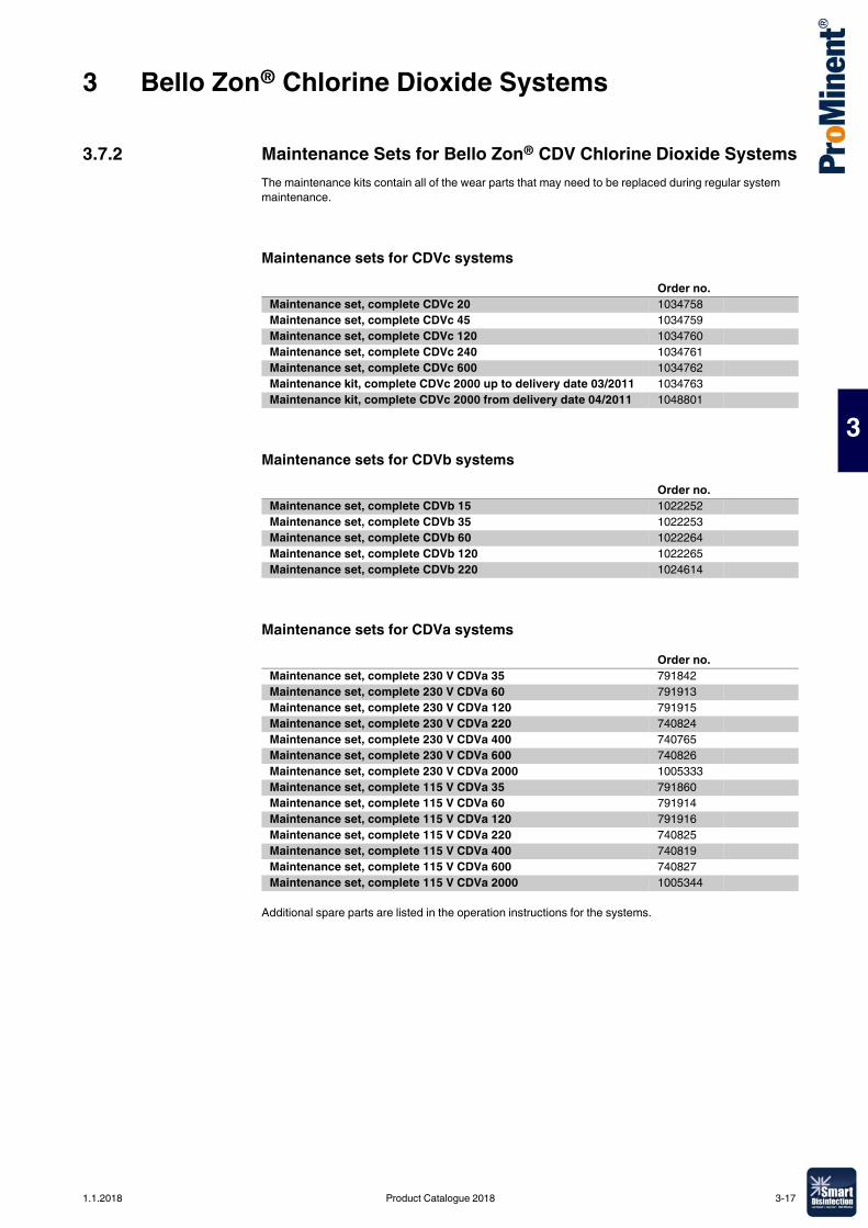
3 Bello Zon® Chlorine Dioxide Systems
3
3.7.2 Maintenance Sets for Bello Zon® CDV Chlorine Dioxide SystemsThe maintenance kits contain all of the wear parts that may need to be replaced during regular system maintenance.
Maintenance sets for CDVc systems
Maintenance sets for CDVb systems
Maintenance sets for CDVa systems
Additional spare parts are listed in the operation instructions for the systems.
Order no.Maintenance set, complete CDVc 20 1034758Maintenance set, complete CDVc 45 1034759Maintenance set, complete CDVc 120 1034760Maintenance set, complete CDVc 240 1034761Maintenance set, complete CDVc 600 1034762Maintenance kit, complete CDVc 2000 up to delivery date 03/2011 1034763Maintenance kit, complete CDVc 2000 from delivery date 04/2011 1048801
Order no.Maintenance set, complete CDVb 15 1022252Maintenance set, complete CDVb 35 1022253Maintenance set, complete CDVb 60 1022264Maintenance set, complete CDVb 120 1022265Maintenance set, complete CDVb 220 1024614
Order no.Maintenance set, complete 230 V CDVa 35 791842Maintenance set, complete 230 V CDVa 60 791913Maintenance set, complete 230 V CDVa 120 791915Maintenance set, complete 230 V CDVa 220 740824Maintenance set, complete 230 V CDVa 400 740765Maintenance set, complete 230 V CDVa 600 740826Maintenance set, complete 230 V CDVa 2000 1005333Maintenance set, complete 115 V CDVa 35 791860Maintenance set, complete 115 V CDVa 60 791914Maintenance set, complete 115 V CDVa 120 791916Maintenance set, complete 115 V CDVa 220 740825Maintenance set, complete 115 V CDVa 400 740819Maintenance set, complete 115 V CDVa 600 740827Maintenance set, complete 115 V CDVa 2000 1005344
1.1.2018 Product Catalogue 2018 3-17
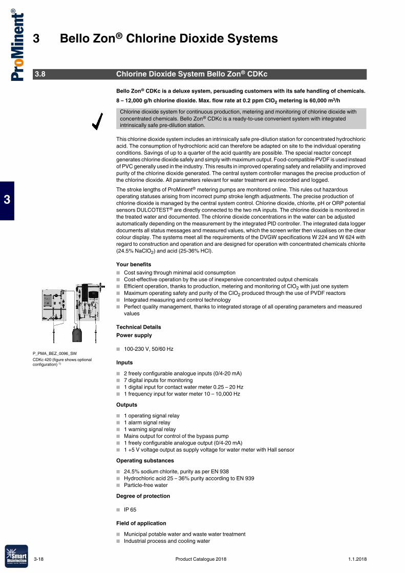
3 Bello Zon® Chlorine Dioxide Systems
3
Bello Zon® CDKc is a deluxe system, persuading customers with its safe handling of chemicals.8 – 12,000 g/h chlorine dioxide. Max. flow rate at 0.2 ppm ClO2 metering is 60,000 m3/h
This chlorine dioxide system includes an intrinsically safe pre-dilution station for concentrated hydrochloric acid. The consumption of hydrochloric acid can therefore be adapted on site to the individual operating conditions. Savings of up to a quarter of the acid quantity are possible. The special reactor concept generates chlorine dioxide safely and simply with maximum output. Food-compatible PVDF is used instead of PVC generally used in the industry. This results in improved operating safety and reliability and improved purity of the chlorine dioxide generated. The central system controller manages the precise production of the chlorine dioxide. All parameters relevant for water treatment are recorded and logged.The stroke lengths of ProMinent® metering pumps are monitored online. This rules out hazardous operating statuses arising from incorrect pump stroke length adjustments. The precise production of chlorine dioxide is managed by the central system control. Chlorine dioxide, chlorite, pH or ORP potential sensors DULCOTEST® are directly connected to the two mA inputs. The chlorine dioxide is monitored in the treated water and documented. The chlorine dioxide concentrations in the water can be adjusted automatically depending on the measurement by the integrated PID controller. The integrated data logger documents all status messages and measured values, which the screen writer then visualises on the clear colour display. The systems meet all the requirements of the DVGW specifications W 224 and W 624 with regard to construction and operation and are designed for operation with concentrated chemicals chlorite (24.5% NaClO2) and acid (25-36% HCl).
Your benefits� Cost saving through minimal acid consumption� Cost-effective operation by the use of inexpensive concentrated output chemicals� Efficient operation, thanks to production, metering and monitoring of ClO2 with just one system� Maximum operating safety and purity of the CIO2 produced through the use of PVDF reactors � Integrated measuring and control technology� Perfect quality management, thanks to integrated storage of all operating parameters and measured
values
Technical DetailsPower supply
� 100-230 V, 50/60 Hz
Inputs� 2 freely configurable analogue inputs (0/4-20 mA)� 7 digital inputs for monitoring� 1 digital input for contact water meter 0.25 – 20 Hz� 1 frequency input for water meter 10 – 10,000 HzOutputs� 1 operating signal relay� 1 alarm signal relay� 1 warning signal relay� Mains output for control of the bypass pump� 1 freely configurable analogue output (0/4-20 mA)� 1 +5 V voltage output as supply voltage for water meter with Hall sensorOperating substances� 24.5% sodium chlorite, purity as per EN 938� Hydrochloric acid 25 – 36% purity according to EN 939� Particle-free waterDegree of protection
� IP 65
Field of application� Municipal potable water and waste water treatment� Industrial process and cooling water
3.8 Chlorine Dioxide System Bello Zon® CDKc
Chlorine dioxide system for continuous production, metering and monitoring of chlorine dioxide with concentrated chemicals. Bello Zon® CDKc is a ready-to-use convenient system with integrated intrinsically safe pre-dilution station.
P_PMA_BEZ_0096_SWCDKc 420 (figure shows optional configuration) 1)
3-18 Product Catalogue 2018 1.1.2018
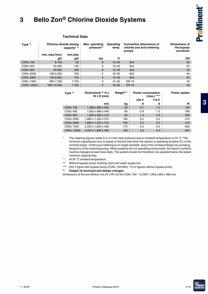
3 Bello Zon® Chlorine Dioxide Systems
3
Technical Data
Dimensions of the pre-dilution unit (H x W x D) for CDKc 150 - 12,000: 1,200 x 900 x 300 mm
Type 1) Chlorine dioxide dosingcapacity* 1)
Max. operatingpressure**
Operatingtemp.
Connection dimensions of chlorite and acid metering pumps
Dimensions ofthe bypassconnector
min.-max./hour min./dayg/h g/d bar °C DN
CDKc 150 8-150 56 8 10–40 6x4 25CDKc 400 20-400 140 8 10–40 8x5 25CDKc 900 45-900 300 8 10–40 8x5 32CDKc 2000 100-2,000 700 5 10–40 8x5 40CDKc 2800 140-2,800 700 5 15–40 8x5 40CDKc 7300 365-7,300 1,750 3 15–40 DN 10 40CDKc 12000 600-12,000 1,750 2 18–40 DN 10 40
Type 1) Dimensions*** H xW x D (mm)
Weight*** Power consumption(max.) ****
Power uptake
230 V 115 V mm kg A A W
CDKc 150 1,380 x 880 x 320 55 0.7 1.2 130CDKc 400 1,650 x 880 x 445 80 0.9 1.2 180CDKc 900 1,920 x 920 x 510 95 1.4 2.5 250CDKc 2000 1,880 x 1,320 x 570 160 2.2 3.5 410CDKc 2800 1,880 x 1,320 x 570 160 2.2 3.5 410CDKc 7300 2,250 x 1,850 x 460 175 5.5 6.4 640CDKc 12000 2,250 x 1,850 x 460 180 5.5 6.4 640
* The metering figures relate to 5 or 2 bar back pressure and an ambient temperature of 20 °C. The minimum capacity/per hour is based on the fact that when the system is operating at below 5% of the nominal power, continuous metering is no longer possible, due to the correspondingly low pumping frequency of the metering pumps. When systems are not operating continuously, the reactor contents must be changed at least twice daily. The system should not, therefore, be operated below the stated minimum capacity/day.
** At 35 °C ambient temperature*** Without bypass pump, flushing valve and water supply line**** 230 V figure with bypass pump (CDKc 150-900), 115 V figures without bypass pump1) Subject to technical and design changes.
1.1.2018 Product Catalogue 2018 3-19
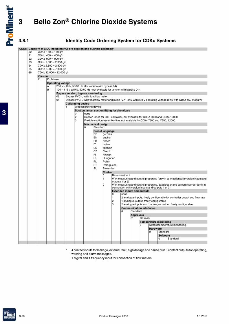
3 Bello Zon® Chlorine Dioxide Systems
3
3.8.1 Identity Code Ordering System for CDKc SystemsCDKc Capacity of ClO2 including HCl pre-dilution and flushing assembly
20 CDKc 150 = 150 g/h21 CDKc 400 = 400 g/h22 CDKc 900 = 900 g/h23 CDKc 2,000 = 2,000 g/h24 CDKc 2,800 = 2,800 g/h25 CDKc 7,300 = 7,300 g/h26 CDKc 12,000 = 12,000 g/h
VersionP ProMinent
Operating voltageA 230 V ±10%, 50/60 Hz (for version with bypass 04)B 100 – 115 V ±10%, 50/60 Hz (not available for version with bypass 04)
Bypass version, bypass monitoring02 Bypass PVC-U with float flow meter 04 Bypass PVC-U with float flow meter and pump (VA) only with 230 V operating voltage (only with CDKc 150-900 g/h)
Calibrating device1 with calibrating device
Suction lance, suction fitting for chemicals0 none2 Suction lance for 200 l container, not available for CDKc 7300 and CDKc 120003 Flexible suction assembly 5 m, not available for CDKc 7300 and CDKc 12000
Mechanical design0 Standard
Preset languageDE germanEN englishFR frenchIT italianES spanishCZ CzechFI FinnishHU HungarianPL PolishPT PortugueseSL Slovenian
Control0 Basic version *)
1 With measuring and control properties (only in connection with version inputs and outputs 1 or 3)
2 With measuring and control properties, data logger and screen recorder (only in connection with version inputs and outputs 1 or 3)Extended inputs and outputs0 none1 2 analogue inputs, freely configurable for controller output and flow rate2 1 analogue output, freely configurable3 2 analogue inputs and 1 analogue output, freely configurable
Communication interfaces0 Standard
Approvals01 CE mark
Temperature monitoring0 without temperature monitoring
Hardware0 Standard
Software0 Standard
* 4 contact inputs for leakage, external fault, high dosage and pause plus 3 contact outputs for operating, warning and alarm messages.1 digital and 1 frequency input for connection of flow meters.
3-20 Product Catalogue 2018 1.1.2018
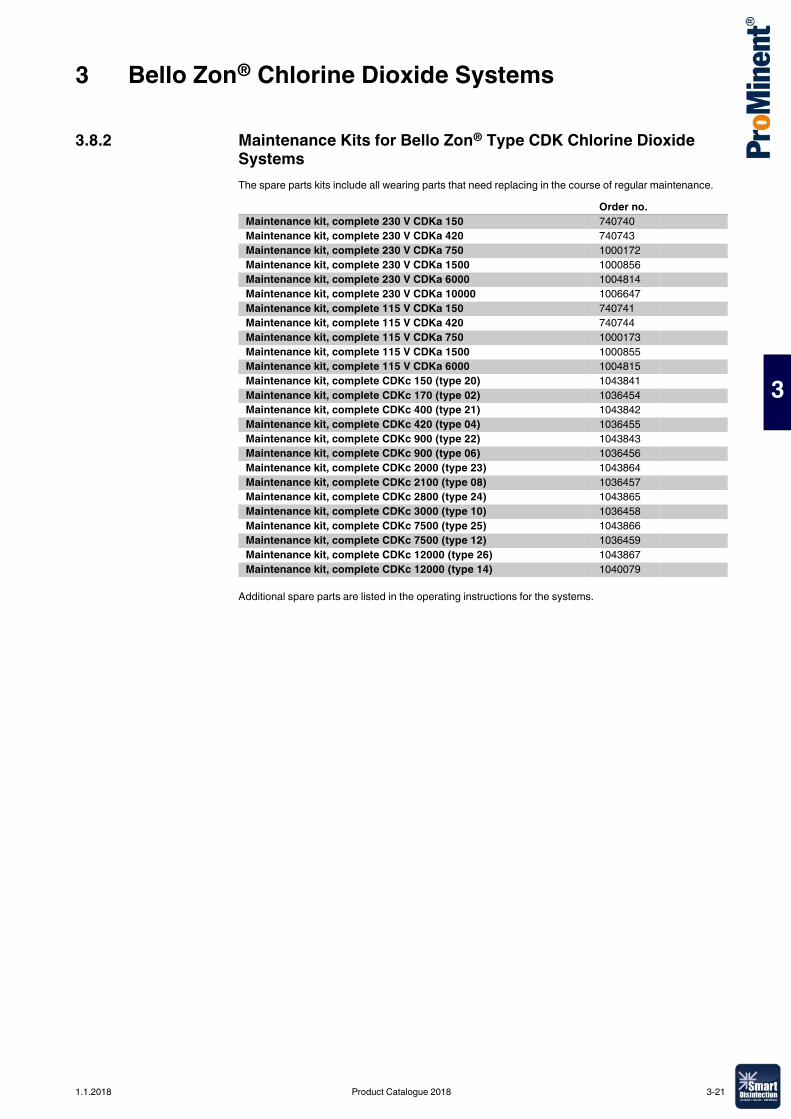
3 Bello Zon® Chlorine Dioxide Systems
3
3.8.2 Maintenance Kits for Bello Zon® Type CDK Chlorine Dioxide SystemsThe spare parts kits include all wearing parts that need replacing in the course of regular maintenance.
Additional spare parts are listed in the operating instructions for the systems.
Order no.Maintenance kit, complete 230 V CDKa 150 740740Maintenance kit, complete 230 V CDKa 420 740743Maintenance kit, complete 230 V CDKa 750 1000172Maintenance kit, complete 230 V CDKa 1500 1000856Maintenance kit, complete 230 V CDKa 6000 1004814Maintenance kit, complete 230 V CDKa 10000 1006647Maintenance kit, complete 115 V CDKa 150 740741Maintenance kit, complete 115 V CDKa 420 740744Maintenance kit, complete 115 V CDKa 750 1000173Maintenance kit, complete 115 V CDKa 1500 1000855Maintenance kit, complete 115 V CDKa 6000 1004815Maintenance kit, complete CDKc 150 (type 20) 1043841Maintenance kit, complete CDKc 170 (type 02) 1036454Maintenance kit, complete CDKc 400 (type 21) 1043842Maintenance kit, complete CDKc 420 (type 04) 1036455Maintenance kit, complete CDKc 900 (type 22) 1043843Maintenance kit, complete CDKc 900 (type 06) 1036456Maintenance kit, complete CDKc 2000 (type 23) 1043864Maintenance kit, complete CDKc 2100 (type 08) 1036457Maintenance kit, complete CDKc 2800 (type 24) 1043865Maintenance kit, complete CDKc 3000 (type 10) 1036458Maintenance kit, complete CDKc 7500 (type 25) 1043866Maintenance kit, complete CDKc 7500 (type 12) 1036459Maintenance kit, complete CDKc 12000 (type 26) 1043867Maintenance kit, complete CDKc 12000 (type 14) 1040079
1.1.2018 Product Catalogue 2018 3-21
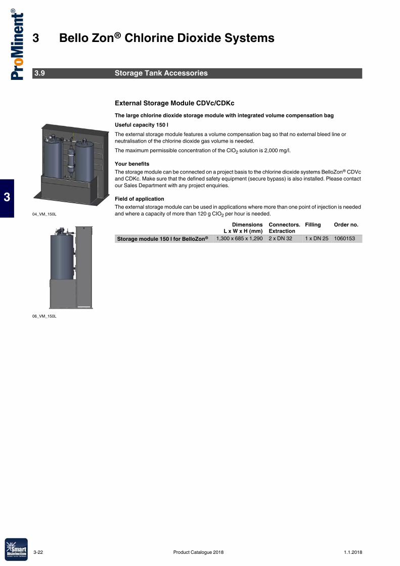
3 Bello Zon® Chlorine Dioxide Systems
3
External Storage Module CDVc/CDKcThe large chlorine dioxide storage module with integrated volume compensation bagUseful capacity 150 lThe external storage module features a volume compensation bag so that no external bleed line or neutralisation of the chlorine dioxide gas volume is needed.The maximum permissible concentration of the ClO2 solution is 2,000 mg/l.
Your benefitsThe storage module can be connected on a project basis to the chlorine dioxide systems BelloZon® CDVc and CDKc. Make sure that the defined safety equipment (secure bypass) is also installed. Please contact our Sales Department with any project enquiries.
Field of applicationThe external storage module can be used in applications where more than one point of injection is needed and where a capacity of more than 120 g CIO2 per hour is needed.
3.9 Storage Tank Accessories
04_VM_150L
06_VM_150L
DimensionsL x W x H (mm)
Connectors. Extraction
Filling Order no.
Storage module 150 l for BelloZon® 1,300 x 685 x 1,290 2 x DN 32 1 x DN 25 1060153
3-22 Product Catalogue 2018 1.1.2018
3 Bello Zon® Chlorine Dioxide Systems
3
Premixers Made of PVCCDVb 15-120 premixers are fully integrated in the plant, provided they are ordered with the Identity Code. The premixer on the CDVb 220 can also be ordered by Identity Code but is supplied loose with the plant. On all other plants, the premixer can be ordered partly by Identity Code or partly as a separate order. The standard delivery package of the premixer includes all PVC couplings, screw hose clips and other fixing materials. On the CDVa 2000 and CDKa 1500–10000, the pre-mixer is in two parts.
Bypass PumpBooster pumps made of cast iron (GG) or stainless steel (SS) for operation in the bypass line. Electrical version 220-230 V, 50 Hz, with integrated overload protection.The required bypass flow should be considered when selecting a suitable bypass pump. The following flow data is recommended for the different plants:
PVC should be used as the material for the bypass. The thickness should at least correspond to the pressure range PN 10, or even better PN 16 (bar).
Technical Data
Accessories
3.10 Bypass Line Accessories
Plant Volume Length Connection nominal diameter
Order no.
l mmCDVb 220, CDKa 150 1.5 594 DN 25 740649CDVa 400, CDKa 420 4.5 756 DN 25 740650CDVa 600, CDKa 750 7.0 1,306 DN 32 740832CDVa 2000, CDKa 1500 13.4 2x1,316 DN 40 1001000CDKa 6000/10000 13.4 2x1,330 DN 50 1003121
Plant type Bypass line Diameter (mm) Flow rate (m3/h)CDV 15 – 600 DN 25 32 0.5 - 2CDV 2,000 DN 40 50 2 - 10CDKa 150 – 420 DN 25 32 0.5 - 2CDKa 750 DN 32 40 1 - 3.5CDKa 1,500 DN 40 50 1.5 - 10CDKa 6,000 – 10,000 DN 50 63 6 - 10CDKc 150 - 900 DN 25 32 0.5 - 2CDKc 2,000 - 2,800 DN 40 50 2 - 10CDKc 7,300 DN 40 50 6 - 10CDKc 12,000 DN 40 50 10 - 15
Type Material Connection suction/discharge side
Pump capacityat 2 bar
Nominalrating
Nominalcurrent
Order no.
inch m3/h W AZHM 3 SS RP 1"/1" 1.2 500 2.3 1051081
Caution: Do not allow pump to come into contact with ClO2!
Order no.Bracket for bypass pump 791474Angle-seat valve PVC DN 25 for throttling the bypass pump 1001877
1.1.2018 Product Catalogue 2018 3-23
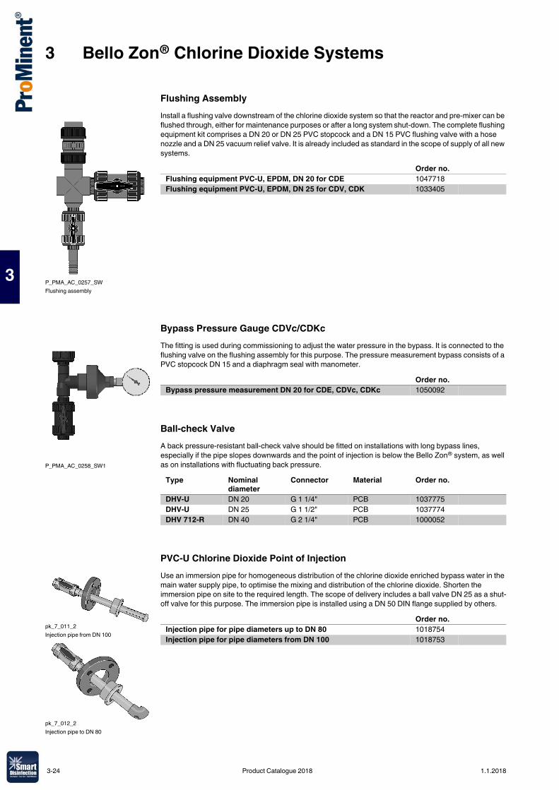
3 Bello Zon® Chlorine Dioxide Systems
3
Flushing AssemblyInstall a flushing valve downstream of the chlorine dioxide system so that the reactor and pre-mixer can be flushed through, either for maintenance purposes or after a long system shut-down. The complete flushing equipment kit comprises a DN 20 or DN 25 PVC stopcock and a DN 15 PVC flushing valve with a hose nozzle and a DN 25 vacuum relief valve. It is already included as standard in the scope of supply of all new systems.
Bypass Pressure Gauge CDVc/CDKcThe fitting is used during commissioning to adjust the water pressure in the bypass. It is connected to the flushing valve on the flushing assembly for this purpose. The pressure measurement bypass consists of a PVC stopcock DN 15 and a diaphragm seal with manometer.
Ball-check ValveA back pressure-resistant ball-check valve should be fitted on installations with long bypass lines, especially if the pipe slopes downwards and the point of injection is below the Bello Zon® system, as well as on installations with fluctuating back pressure.
PVC-U Chlorine Dioxide Point of InjectionUse an immersion pipe for homogeneous distribution of the chlorine dioxide enriched bypass water in the main water supply pipe, to optimise the mixing and distribution of the chlorine dioxide. Shorten the immersion pipe on site to the required length. The scope of delivery includes a ball valve DN 25 as a shut-off valve for this purpose. The immersion pipe is installed using a DN 50 DIN flange supplied by others.
P_PMA_AC_0257_SWFlushing assembly
Order no.Flushing equipment PVC-U, EPDM, DN 20 for CDE 1047718Flushing equipment PVC-U, EPDM, DN 25 for CDV, CDK 1033405
P_PMA_AC_0258_SW1
Order no.Bypass pressure measurement DN 20 for CDE, CDVc, CDKc 1050092
Type Nominal diameter
Connector Material Order no.
DHV-U DN 20 G 1 1/4" PCB 1037775DHV-U DN 25 G 1 1/2" PCB 1037774DHV 712-R DN 40 G 2 1/4" PCB 1000052
pk_7_011_2Injection pipe from DN 100
pk_7_012_2Injection pipe to DN 80
Order no.Injection pipe for pipe diameters up to DN 80 1018754Injection pipe for pipe diameters from DN 100 1018753
3-24 Product Catalogue 2018 1.1.2018
3 Bello Zon® Chlorine Dioxide Systems
3
Inductive Magnetic Flow MetersThe flow meter with transducer MAG 5100 W is especially suitable for water flow measurement in the fields of ground water, potable water, waste water and sludge.
Connection nominal diameter Order no.Inductive magnetic flow meter DN 25 1048775
DN 50 1034685DN 65 1034686DN 80 1034687DN 100 1034688
1.1.2018 Product Catalogue 2018 3-25
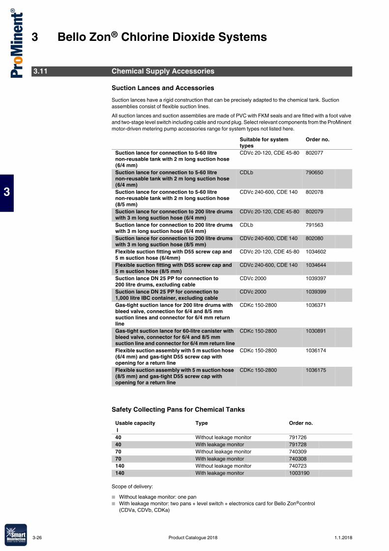
3 Bello Zon® Chlorine Dioxide Systems
3
Suction Lances and AccessoriesSuction lances have a rigid construction that can be precisely adapted to the chemical tank. Suction assemblies consist of flexible suction lines.All suction lances and suction assemblies are made of PVC with FKM seals and are fitted with a foot valve and two-stage level switch including cable and round plug. Select relevant components from the ProMinent motor-driven metering pump accessories range for system types not listed here.
Safety Collecting Pans for Chemical Tanks
Scope of delivery:� Without leakage monitor: one pan� With leakage monitor: two pans + level switch + electronics card for Bello Zon®control
(CDVa, CDVb, CDKa)
3.11 Chemical Supply Accessories
Suitable for system types
Order no.
Suction lance for connection to 5-60 litre non-reusable tank with 2 m long suction hose (6/4 mm)
CDVc 20-120, CDE 45-80 802077
Suction lance for connection to 5-60 litre non-reusable tank with 2 m long suction hose (6/4 mm)
CDLb 790650
Suction lance for connection to 5-60 litre non-reusable tank with 2 m long suction hose (8/5 mm)
CDVc 240-600, CDE 140 802078
Suction lance for connection to 200 litre drums with 3 m long suction hose (6/4 mm)
CDVc 20-120, CDE 45-80 802079
Suction lance for connection to 200 litre drums with 3 m long suction hose (6/4 mm)
CDLb 791563
Suction lance for connection to 200 litre drums with 3 m long suction hose (8/5 mm)
CDVc 240-600, CDE 140 802080
Flexible suction fitting with D55 screw cap and 5 m suction hose (6/4mm)
CDVc 20-120, CDE 45-80 1034602
Flexible suction fitting with D55 screw cap and 5 m suction hose (8/5 mm)
CDVc 240-600, CDE 140 1034644
Suction lance DN 25 PP for connection to 200 litre drums, excluding cable
CDVc 2000 1039397
Suction lance DN 25 PP for connection to 1,000 litre IBC container, excluding cable
CDVc 2000 1039399
Gas-tight suction lance for 200 litre drums with bleed valve, connection for 6/4 and 8/5 mm suction lines and connector for 6/4 mm return line
CDKc 150-2800 1036371
Gas-tight suction lance for 60-litre canister with bleed valve, connector for 6/4 and 8/5 mm suction line and connector for 6/4 mm return line
CDKc 150-2800 1030891
Flexible suction assembly with 5 m suction hose (6/4 mm) and gas-tight D55 screw cap with opening for a return line
CDKc 150-2800 1036174
Flexible suction assembly with 5 m suction hose (8/5 mm) and gas-tight D55 screw cap with opening for a return line
CDKc 150-2800 1036175
Usable capacity Type Order no. l40 Without leakage monitor 79172640 With leakage monitor 79172870 Without leakage monitor 74030970 With leakage monitor 740308140 Without leakage monitor 740723140 With leakage monitor 1003190
3-26 Product Catalogue 2018 1.1.2018
3 Bello Zon® Chlorine Dioxide Systems
3
Extension cable, 3-coreFor 2-stage level switches, with round plug and round plug coupling.
Calibration Free-standing Cylinder for Bello Zon® CDEa
Leakage Monitor for CDVc and CDKc Systems
Consisting of 1 level switch to be fitted in the 40, 70 or 140 l safety drip pans without leakage monitor and connected to the control of the Bello Zon® CDVc and CDKc.
Drip Pan with Grating to Install Two 200 l Barrels
Meets the requirements of the German Water Resources Act (WHG) and possesses a general building supervision approval from DIBt, Berlin.
Bello Zon® AcidComponent 1 for Bello Zon® chlorine dioxide production system.
Bello Zon® ChloriteComponent 2 for Bello Zon® chlorine dioxide production system.
pk_1_126 Cable length Fig. Order no. m
Extension cable, 3-core 3 pk_1_126 1005559
Order no.Measuring cylinder, tall, 500 ml PP 790661
Order no.Level switch with litz wire 5 m 1003191
Material Weight External dimensionWxDxH
Effective areaWxD
Collectingvolume
kg mm mm lPolyethylene ca. 22 1,230 x 820 x 435 1,160 x 750 220
Order no.Drip pan with grating 1027211
Order no.Bello Zon® Acid 25 l 1027594Bello Zon® Acid 200 l 950131
Order no.Bello Zon® Chlorite 10 l 1026422Bello Zon® Chlorite 25 l 1027595Bello Zon® Chlorite 200 l 950136
1.1.2018 Product Catalogue 2018 3-27
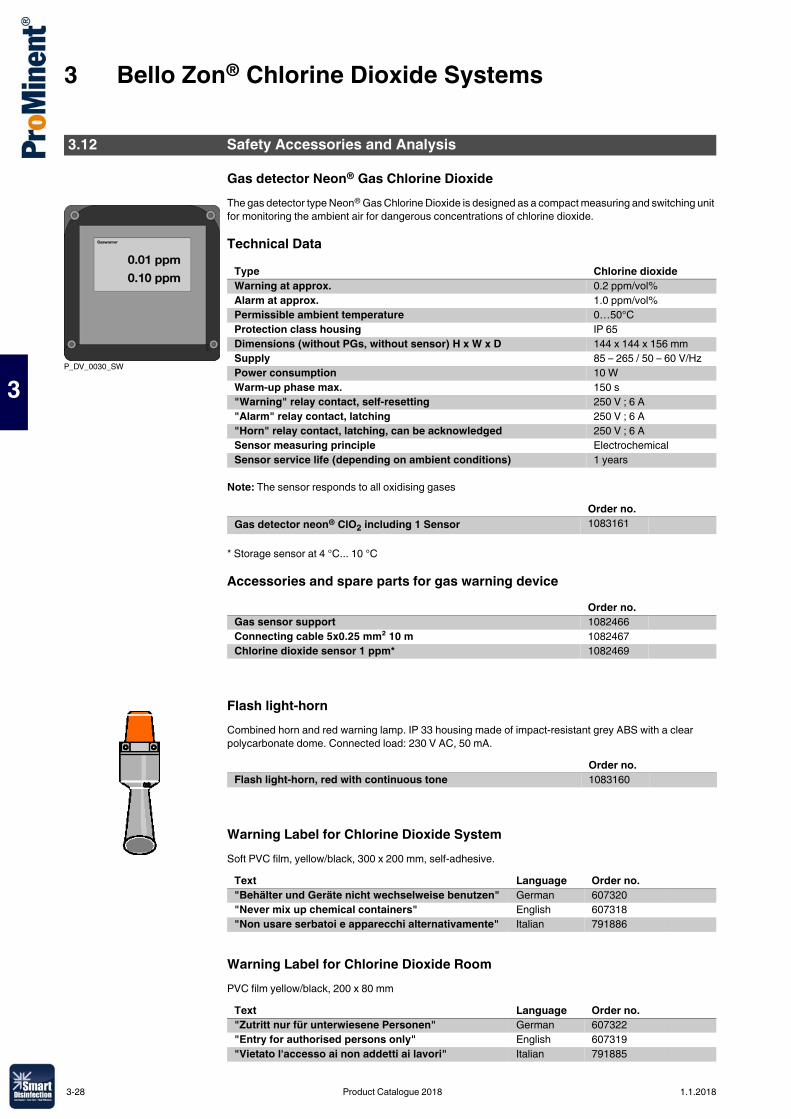
3 Bello Zon® Chlorine Dioxide Systems
3
Gas detector Neon® Gas Chlorine DioxideThe gas detector type Neon® Gas Chlorine Dioxide is designed as a compact measuring and switching unit for monitoring the ambient air for dangerous concentrations of chlorine dioxide.
Technical Data
Note: The sensor responds to all oxidising gases
* Storage sensor at 4 °C... 10 °C
Accessories and spare parts for gas warning device
Flash light-hornCombined horn and red warning lamp. IP 33 housing made of impact-resistant grey ABS with a clear polycarbonate dome. Connected load: 230 V AC, 50 mA.
Warning Label for Chlorine Dioxide SystemSoft PVC film, yellow/black, 300 x 200 mm, self-adhesive.
Warning Label for Chlorine Dioxide RoomPVC film yellow/black, 200 x 80 mm
3.12 Safety Accessories and Analysis
P_DV_0030_SW
Type Chlorine dioxideWarning at approx. 0.2 ppm/vol%Alarm at approx. 1.0 ppm/vol%Permissible ambient temperature 0…50°CProtection class housing IP 65Dimensions (without PGs, without sensor) H x W x D 144 x 144 x 156 mmSupply 85 – 265 / 50 – 60 V/HzPower consumption 10 WWarm-up phase max. 150 s"Warning" relay contact, self-resetting 250 V ; 6 A"Alarm" relay contact, latching 250 V ; 6 A"Horn" relay contact, latching, can be acknowledged 250 V ; 6 ASensor measuring principle Electrochemical Sensor service life (depending on ambient conditions) 1 years
Order no.Gas detector neon® ClO2 including 1 Sensor 1083161
Order no.Gas sensor support 1082466Connecting cable 5x0.25 mm² 10 m 1082467Chlorine dioxide sensor 1 ppm* 1082469
Order no.Flash light-horn, red with continuous tone 1083160
Text Language Order no."Behälter und Geräte nicht wechselweise benutzen" German 607320"Never mix up chemical containers" English 607318"Non usare serbatoi e apparecchi alternativamente" Italian 791886
Text Language Order no."Zutritt nur für unterwiesene Personen" German 607322"Entry for authorised persons only" English 607319"Vietato l'accesso ai non addetti ai lavori" Italian 791885
3-28 Product Catalogue 2018 1.1.2018
3 Bello Zon® Chlorine Dioxide Systems
3
Acid Fume SeparatorAcid vapour separator, filled with acid-binding granules for the absorption of hydrochloric acid vapours.
Photometers DT1, DT2 and DT4� Portable, compact photometer� Simple operation with text support� Safe, simple measurement of chlorine, chlorine dioxide, fluoride, chlorite, H2O2, bromine, ozone,
pH and cyanuric acid� Calibratable
Technical Data
The standard delivery package for the photometers includes accessories, cuvettes and reagents
Order no.Acid vapour separator CDKa 0.7 l 1009987Acid vapour separator CDKc 0.13 l 1034692Spare back of binder 0.15 l CDKc 1035854Spare back of binder 0.7 l CDKa 1010500
Measuring ranges of the DT1B 0.05 … 6.0 mg/l free chlorine (DPD1) +total chlorine (DPD1+3)5 ... 200 mg/l free chlorine (high range)0.1 … 13.0 mg/l bromine (DPD1)0.05 … 11 mg/l chlorine dioxide (DPD1)0.03 … 4.0 mg/l ozone (DPD4)6.5 … 8.4 pH (phenol red)1 … 80 mg/l cyanuric acid
Measuring ranges of the DT2C 0.05 … 2.0 mg/l fluoride0.05 … 6.0 mg/l free chlorine and total chlorine0.05 … 11.0 mg/l chlorine dioxide
DT4 ranges 0.03 … 2.5 mg/l chlorite0.05 … 11 mg/l chlorine dioxide0.05 … 6 mg/l chlorine
Measuring tolerance Dependent upon measured value and measuring methodBattery 4 AA/LR6 batteriesPermissible ambient temperature
5…40 °C
Relative humidity 30 … 90% (non-condensing)Material Housing material: ABS
Keypad: PolycarbonateDimensions L x W x H (mm) 190 x 110 x 55Weight 0.4 kg
P_DT_0074_SWPhotometer
Order no.Photometer DT1B Complete with carrying case 1039315Photometer DT2C Complete with carrying case 1039316Photometer DT4B Complete with carrying case 1039318
1.1.2018 Product Catalogue 2018 3-29
3 Bello Zon® Chlorine Dioxide Systems
3
Case for Chlorine Dioxyde Depletion TestThe case contains the equipment needed for a ClO2 depletion test. A photometer and the starting chemicals are also needed.Important: Only allow trained personnel to use the case!
Consumables for Analysis
* replaces DPD1 buffer, 15 ml (1002857) and DPD1 reagent, 15 ml (1002858)** replaces DPD3 solution, 15 ml (1002859)DPD reagents for measurement of excess chlorine, ozone or chlorine dioxide in the water, in conjunction with a Lovibond comparator.
Order no.Measuring case 1042890
Order no.DPD1 tablets, 100 pieces * 1061892DPD3 tablets, 100 pieces ** 1061893Glycine tablets, 20 pieces 1061944Phenol red tablets 100 pieces 305532Cyanuric acid tablets, 100 pieces 1039744SPADNS reagent, 250 ml for fluoride detection 1010381Calibration standard fluoride 1 mg/l, for calibration of the photometer during fluoride determination
1010382
3 pieces replacement cuvettes; round cuvettes with lid for DPD, phenol red and cyanuric acid detection (DT1, DT1B, DT4, DT4B, DT2B, DT2C)
1007566
3 pieces replacement cuvettes for fluoride detection (DT2B and DT2C) 1010396Chlorine dioxide tablets No. 1, 250 no. 1039732Chlorine dioxide tablets No. 2, 250 no. 1039733Chlorine HR tablets, 100 pieces 1075056Acidifying tablets, 100 pieces 1075057
Amount Order no.DPD tablets no. 1 100 501319DPD tablets no. 2 100 501320DPD tablets no. 3 100 501321DPD tablets no. 4 100 501322
3-30 Product Catalogue 2018 1.1.2018
4 Electrolysis Systems CHLORINSITU® and DULCO®Lyse
4
4.0.1Product Catalogue 2018
Chlorine and sodium hydroxide are produced in-situ with electrolysis by passing an electric current through salt water.In an open electrolysis cell (type CHLORINSITU® II), the electrochemical reaction takes place in a flow chamber, so that the freshly produced chlorine gas immediately reacts with the sodium hydroxide to form sodium hypochlorite. A saturated brine is used as a salt solution, which is produced in a separate salt dissolving tank from salt of a defined quality. The benefit of open electrolysis cells lies in the simple construction of the equipment, its ease of maintenance and low investment compared with membrane electrolysis systems. The disadvantage is the low output of salt solution, higher entrainment of chloride into the water to be treated, higher power consumption and relatively low chlorine concentrations (5 g/l FAC) in the end product.In membrane electrolysis, the electrochemical reaction takes place in two electrode chambers separated by a diaphragm, so that the formation of the freshly produced chlorine gas and sodium hydroxide is physically separated. Systems of type CHLORINSITU® III and CHLORINSITU® III Compact bring the reaction mixtures of both electrode chambers together again after the electrochemical reaction to produce a stock solution of sodium hypochlorite (25 g/l FAC), which can be stored temporarily and metered as needed.With systems of type CHLORINSITU® IV Compact and CHLORINSITU® V, the highly pure chlorine gas is fed into the water to be treated through an injector and under constant vacuum, where it dissolves as hypochlorous acid. In systems of type CHLORINSITU® V Plus, any excess chlorine gas produced is combined with the sodium hydroxide, as in the CHLORINSITU® III system, to form sodium hypochlorite and is then stored temporarily. The systems therefore only need to be designed for average chlorine demand, as peaks of capacity can be compensated for from the sodium hypochlorite temporary storage tank. In all systems of types CHLORINSITU® IV Compact, CHLORINSITU® V and CHLORINSITU® V Plus, the sodium hydroxide produced during electrolysis is stored temporarily and metered in, as required, to correct the pH value.The benefit of membrane systems lies in their excellent efficiency (85 % brine output) and minimal entrainment of chloride compared with open electrolysis cells. With systems of type CHLORINSITU® V and CHLORINSITU® V Plus, the entrainment of chloride and chlorate from the electrolysis cell into the water to be treated can be avoided completely. In membrane cell electrolysis systems for producing sodium hypochlorite, the higher output results in solutions with a significantly higher chlorine content than is the case with open electrolysis cells.� Disinfection from natural sodium chloride� No handling of hazardous chemicals� High-purity product, thanks to production in situ and short temporary storage periods� The chlorine gas is generated under a constant vacuum, absolutely reliably and with maximum
operating safety, thanks to the units being designed as vacuum systems� Chlorine generation and pH correction with one system (CHLORINSITU® IV Compact,
CHLORINSITU® V and CHLORINSITU® V Plus)� Improved working conditions for operating personnel� No risk of confusing dangerous chemical tanks
4.1 Electrolysis Systems CHLORINSITU®
1.1.2018 Product Catalogue 2018 4-1
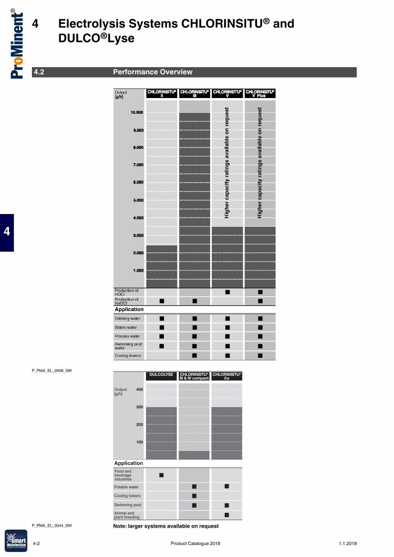
4 Electrolysis Systems CHLORINSITU® and DULCO®Lyse
4
P_PMA_EL_0008_SW
P_PMA_EL_0044_SW Note: larger systems available on request
4.2 Performance Overview
ApplicationFood andbeverage industries
Potable water
Cooling towers
Swimming pool
Animal andplant breeding
4-2 Product Catalogue 2018 1.1.2018
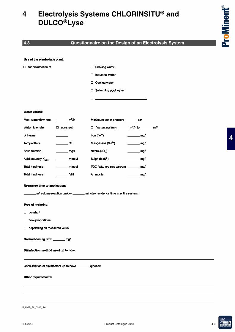
4 Electrolysis Systems CHLORINSITU® and DULCO®Lyse
4
P_PMA_EL_0045_SW
4.3 Questionnaire on the Design of an Electrolysis System
1.1.2018 Product Catalogue 2018 4-3
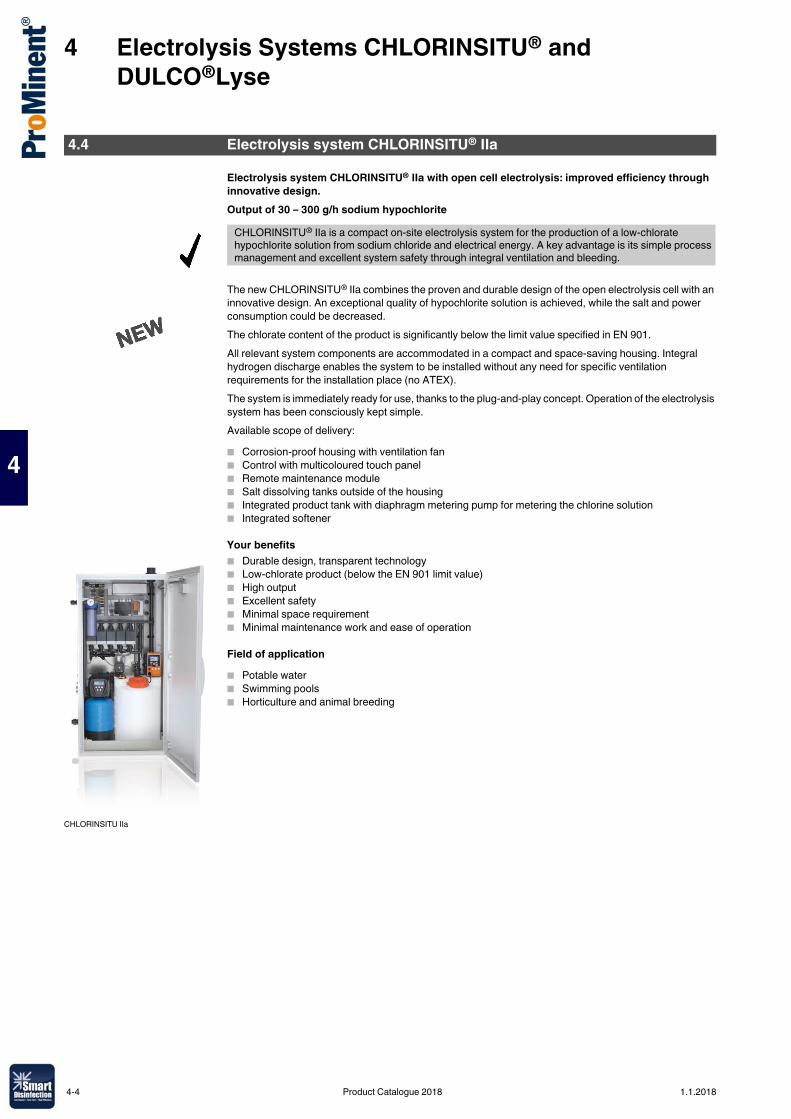
4 Electrolysis Systems CHLORINSITU® and DULCO®Lyse
4
Electrolysis system CHLORINSITU® IIa with open cell electrolysis: improved efficiency through innovative design.Output of 30 – 300 g/h sodium hypochlorite
The new CHLORINSITU® IIa combines the proven and durable design of the open electrolysis cell with an innovative design. An exceptional quality of hypochlorite solution is achieved, while the salt and power consumption could be decreased.The chlorate content of the product is significantly below the limit value specified in EN 901.All relevant system components are accommodated in a compact and space-saving housing. Integral hydrogen discharge enables the system to be installed without any need for specific ventilation requirements for the installation place (no ATEX).The system is immediately ready for use, thanks to the plug-and-play concept. Operation of the electrolysis system has been consciously kept simple.Available scope of delivery:� Corrosion-proof housing with ventilation fan� Control with multicoloured touch panel� Remote maintenance module� Salt dissolving tanks outside of the housing� Integrated product tank with diaphragm metering pump for metering the chlorine solution� Integrated softener
Your benefits� Durable design, transparent technology� Low-chlorate product (below the EN 901 limit value)� High output� Excellent safety� Minimal space requirement� Minimal maintenance work and ease of operation
Field of application� Potable water� Swimming pools� Horticulture and animal breeding
4.4 Electrolysis system CHLORINSITU® IIa
CHLORINSITU® IIa is a compact on-site electrolysis system for the production of a low-chlorate hypochlorite solution from sodium chloride and electrical energy. A key advantage is its simple process management and excellent system safety through integral ventilation and bleeding.
CHLORINSITU IIa
4-4 Product Catalogue 2018 1.1.2018
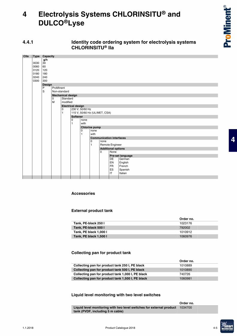
4 Electrolysis Systems CHLORINSITU® and DULCO®Lyse
4
4.4.1 Identity code ordering system for electrolysis systems CHLORINSITU® IIa
Accessories
External product tank
Collecting pan for product tank
Liquid level monitoring with two level switches
CIIa Type Capacity g/h
0030 300060 600120 1200180 1800240 2400300 300
DesignP ProMinentS Non-standard
Mechanical design0 StandardM modified
Electrical design0 230 V, 50/60 Hz1 115 V, 50/60 Hz (UL/MET, CSA)
Softener0 none1 with
Chlorine pump0 none1 with
Communication interfaces0 none1 Remote Engineer
Additional options0 None
Pre-set languageDE GermanEN EnglishFR FrenchES SpanishIT Italian
Order no.Tank, PE-black 250 l 1023176Tank, PE-black 500 l 792002Tank, PE black 1,000 l 1010912Tank, PE black 1,500 l 1060976
Order no.Collecting pan for product tank 250 l, PE black 1010889Collecting pan for product tank 500 l, PE black 1010890Collecting pan for product tank 1,000 l, PE black 740726Collecting pan for product tank 1,500 l, PE black 1060981
Order no.Liquid level monitoring with two level switches for external product tank (PVDF, including 5 m cable)
1034700
1.1.2018 Product Catalogue 2018 4-5
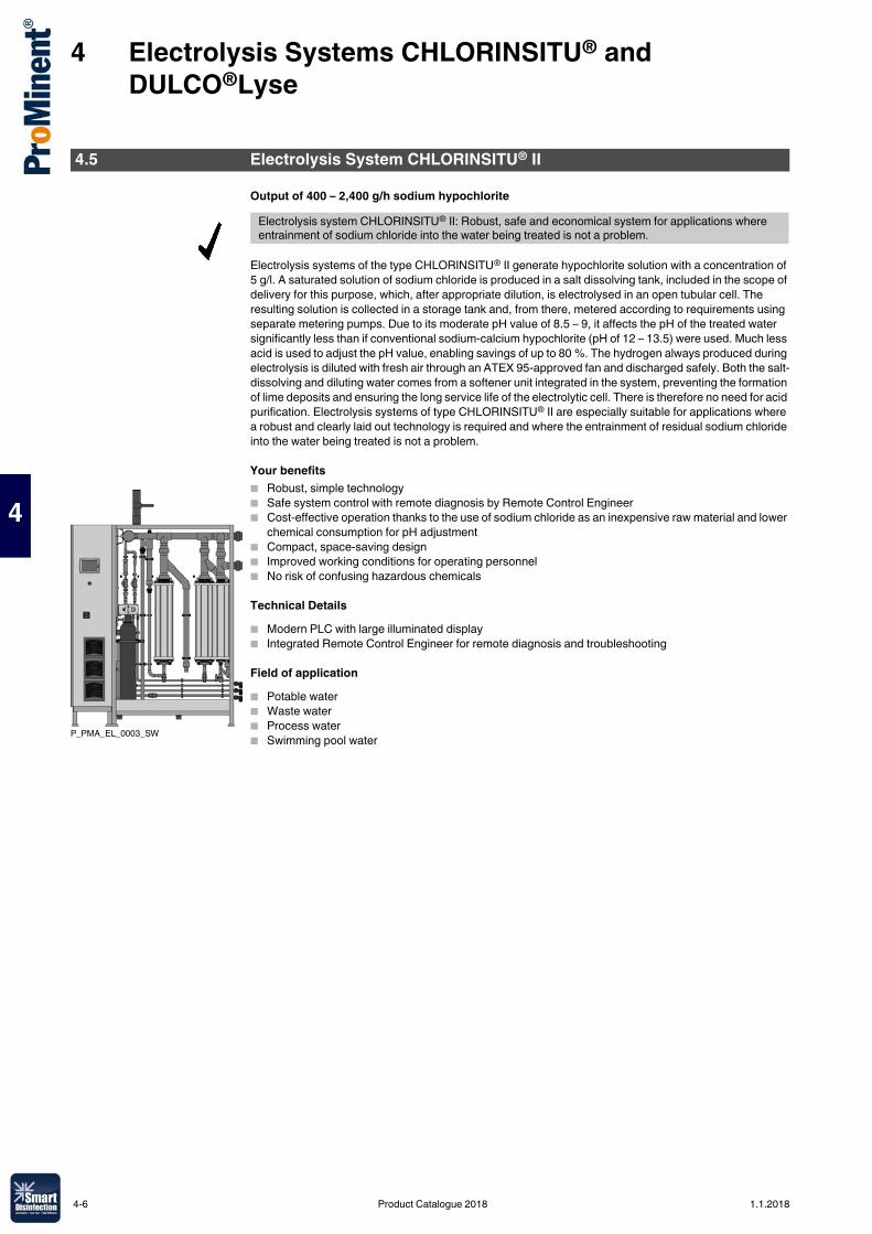
4 Electrolysis Systems CHLORINSITU® and DULCO®Lyse
4
Output of 400 – 2,400 g/h sodium hypochlorite
Electrolysis systems of the type CHLORINSITU® II generate hypochlorite solution with a concentration of 5 g/l. A saturated solution of sodium chloride is produced in a salt dissolving tank, included in the scope of delivery for this purpose, which, after appropriate dilution, is electrolysed in an open tubular cell. The resulting solution is collected in a storage tank and, from there, metered according to requirements using separate metering pumps. Due to its moderate pH value of 8.5 – 9, it affects the pH of the treated water significantly less than if conventional sodium-calcium hypochlorite (pH of 12 – 13.5) were used. Much less acid is used to adjust the pH value, enabling savings of up to 80 %. The hydrogen always produced during electrolysis is diluted with fresh air through an ATEX 95-approved fan and discharged safely. Both the salt-dissolving and diluting water comes from a softener unit integrated in the system, preventing the formation of lime deposits and ensuring the long service life of the electrolytic cell. There is therefore no need for acid purification. Electrolysis systems of type CHLORINSITU® II are especially suitable for applications where a robust and clearly laid out technology is required and where the entrainment of residual sodium chloride into the water being treated is not a problem.
Your benefits� Robust, simple technology� Safe system control with remote diagnosis by Remote Control Engineer� Cost-effective operation thanks to the use of sodium chloride as an inexpensive raw material and lower
chemical consumption for pH adjustment� Compact, space-saving design� Improved working conditions for operating personnel� No risk of confusing hazardous chemicals
Technical Details� Modern PLC with large illuminated display� Integrated Remote Control Engineer for remote diagnosis and troubleshooting
Field of application� Potable water� Waste water� Process water� Swimming pool water
4.5 Electrolysis System CHLORINSITU® II
Electrolysis system CHLORINSITU® II: Robust, safe and economical system for applications where entrainment of sodium chloride into the water being treated is not a problem.
P_PMA_EL_0003_SW
4-6 Product Catalogue 2018 1.1.2018
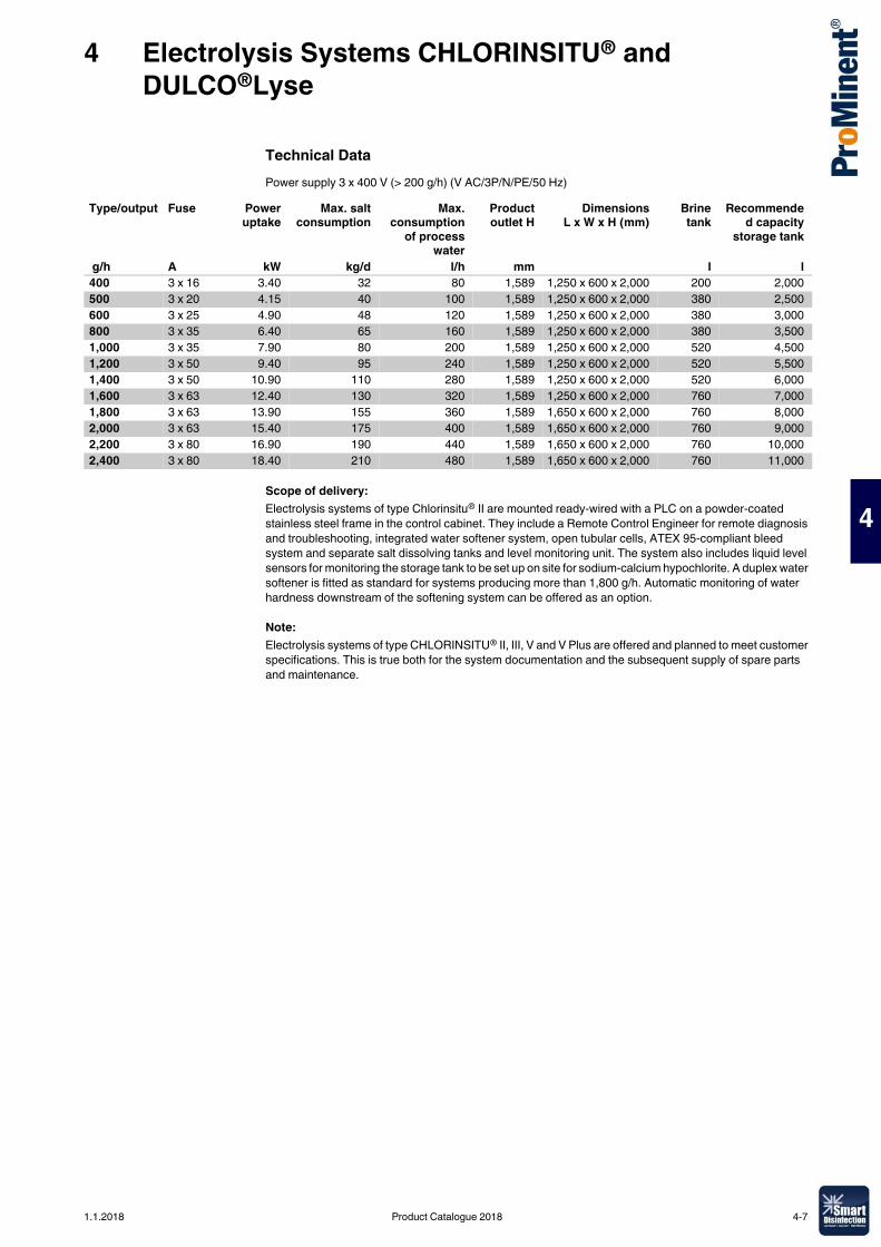
4 Electrolysis Systems CHLORINSITU® and DULCO®Lyse
4
Technical DataPower supply 3 x 400 V (> 200 g/h) (V AC/3P/N/PE/50 Hz)
Scope of delivery: Electrolysis systems of type Chlorinsitu® II are mounted ready-wired with a PLC on a powder-coated stainless steel frame in the control cabinet. They include a Remote Control Engineer for remote diagnosis and troubleshooting, integrated water softener system, open tubular cells, ATEX 95-compliant bleed system and separate salt dissolving tanks and level monitoring unit. The system also includes liquid level sensors for monitoring the storage tank to be set up on site for sodium-calcium hypochlorite. A duplex water softener is fitted as standard for systems producing more than 1,800 g/h. Automatic monitoring of water hardness downstream of the softening system can be offered as an option.
Note:Electrolysis systems of type CHLORINSITU® II, III, V and V Plus are offered and planned to meet customer specifications. This is true both for the system documentation and the subsequent supply of spare parts and maintenance.
Type/output Fuse Poweruptake
Max. saltconsumption
Max.consumption
of processwater
Productoutlet H
DimensionsL x W x H (mm)
Brinetank
Recommended capacity
storage tank
g/h A kW kg/d l/h mm l l400 3 x 16 3.40 32 80 1,589 1,250 x 600 x 2,000 200 2,000500 3 x 20 4.15 40 100 1,589 1,250 x 600 x 2,000 380 2,500600 3 x 25 4.90 48 120 1,589 1,250 x 600 x 2,000 380 3,000800 3 x 35 6.40 65 160 1,589 1,250 x 600 x 2,000 380 3,5001,000 3 x 35 7.90 80 200 1,589 1,250 x 600 x 2,000 520 4,5001,200 3 x 50 9.40 95 240 1,589 1,250 x 600 x 2,000 520 5,5001,400 3 x 50 10.90 110 280 1,589 1,250 x 600 x 2,000 520 6,0001,600 3 x 63 12.40 130 320 1,589 1,250 x 600 x 2,000 760 7,0001,800 3 x 63 13.90 155 360 1,589 1,650 x 600 x 2,000 760 8,0002,000 3 x 63 15.40 175 400 1,589 1,650 x 600 x 2,000 760 9,0002,200 3 x 80 16.90 190 440 1,589 1,650 x 600 x 2,000 760 10,0002,400 3 x 80 18.40 210 480 1,589 1,650 x 600 x 2,000 760 11,000
1.1.2018 Product Catalogue 2018 4-7
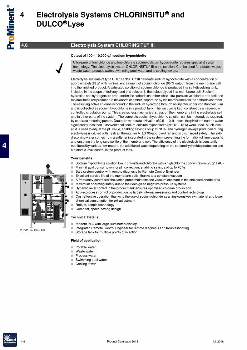
4 Electrolysis Systems CHLORINSITU® and DULCO®Lyse
4
Output of 100 – 10,000 g/h sodium hypochlorite
Electrolysis systems of type CHLORINSITU® III generate sodium hypochlorite with a concentration of approximately 25 g/l with minimal entrainment of sodium chloride (85 % output) from the membrane cell into the finished product. A saturated solution of sodium chloride is produced in a salt-dissolving tank, included in the scope of delivery, and this solution is then electrolysed in a membrane cell. Sodium hydroxide and hydrogen are produced in the cathode chamber while ultra-pure active chlorine and a diluted residual brine are produced in the anode chamber, separated by the membrane from the cathode chamber. The resulting active chlorine is bound to the sodium hydroxide through an injector under constant vacuum and is collected as sodium hypochlorite in a product tank. The vacuum is kept constant by a frequency-controlled circulation pump. This creates less mechanical stress on the membrane in the electrolysis cell and in other parts of the system. The complete sodium hypochlorite solution can be metered, as required, by separate metering pumps. Due to its moderate pH value of 9.5 – 10, it affects the pH of the treated water significantly less than if conventional sodium-calcium hypochlorite (pH 12 – 13.5) were used. Much less acid is used to adjust the pH value, enabling savings of up to 70 %. The hydrogen always produced during electrolysis is diluted with fresh air through an ATEX 95-approved fan and is discharged safely. The salt-dissolving water comes from a softener integrated in the system, preventing the formation of lime deposits and ensuring the long service life of the membrane cell. The efficiency of the electrolysis is constantly monitored by various flow meters, the addition of water depending on the sodium hydroxide production and a dynamic level control in the product tank.
Your benefits� Sodium hypochlorite solution low in chloride and chlorate with a high chlorine concentration (25 g/l FAC)� Minimal acid consumption for pH correction, enabling savings of up to 70 %� Safe system control with remote diagnosis by Remote Control Engineer� Excellent service life of the membrane cells, thanks to a constant vacuum� A frequency-controlled circulation pump maintains the vacuum constant in the enclosed anode area� Maximum operating safety due to their design as negative pressure systems� Dynamic level control in the product tank ensures optimised chlorine production� Active process control of production by largely internal measuring and control technology� Cost-effective operation thanks to the use of sodium chloride as an inexpensive raw material and lower
chemical consumption for pH adjustment� Robust, simple technology� Compact, space-saving design
Technical Details� Modern PLC with large illuminated display� Integrated Remote Control Engineer for remote diagnosis and troubleshooting� Storage tank for multiple points of injection
Field of application� Potable water� Waste water� Process water� Swimming pool water� Cooling tower
4.6 Electrolysis System CHLORINSITU® III
Ultra-pure or low-chloride and low-chlorate sodium-calcium hypochlorite requires specialist system technology. The electrolysis system CHLORINSITU® III is the solution. Can be used for potable water, waste water, process water, swimming pool water and in cooling towers.
P_PMA_EL_0004_SW
4-8 Product Catalogue 2018 1.1.2018
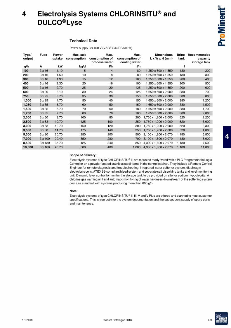
4 Electrolysis Systems CHLORINSITU® and DULCO®Lyse
4
Technical DataPower supply 3 x 400 V (VAC/3P/N/PE/50 Hz)
Scope of delivery:Electrolysis systems of type CHLORINSITU® III are mounted ready-wired with a PLC Programmable Logic Controller on a powder-coated stainless steel frame in the control cabinet. They include a Remote Control Engineer for remote diagnosis and troubleshooting, integrated water softener system, diaphragm electrolysis cells, ATEX 95-compliant bleed system and separate salt dissolving tanks and level monitoring unit. Dynamic level control to monitor the storage tank to be provided on site for sodium hypochlorite. A chlorine gas warning unit and automatic monitoring of water hardness downstream of the softening system come as standard with systems producing more than 600 g/h.
Note:Electrolysis systems of type CHLORINSITU® II, III, V and V Plus are offered and planned to meet customer specifications. This is true both for the system documentation and the subsequent supply of spare parts and maintenance.
Type/output
Fuse Poweruptake
Max. saltconsumption
Max.consumption of
process water
Max.consumption of
cooling water
DimensionsL x W x H (mm)
Brinetank
Recommendedcapacity
storage tank g/h A kW kg/d l/h l/h l l100 3 x 16 1.10 5 4 80 1,250 x 600 x 1,550 130 200200 3 x 16 1.50 10 8 80 1,250 x 600 x 1,550 130 300300 3 x 16 1.90 15 12 100 1,250 x 600 x 1,550 200 400400 3 x 16 2.30 20 16 100 1,250 x 600 x 1,550 200 500500 3 x 16 2.70 25 20 125 1,250 x 600 x 1,550 200 600600 3 x 20 3.10 30 24 125 1,650 x 600 x 2,000 380 700750 3 x 25 3.70 35 30 150 1,650 x 600 x 2,000 380 8001,000 3 x 25 4.70 50 40 150 1,650 x 600 x 2,000 380 1,2001,250 3 x 35 5.70 60 50 150 1,650 x 600 x 2,000 380 1,5001,500 3 x 35 6.70 70 60 180 1,650 x 600 x 2,000 380 1,7001,750 3 x 35 7.70 80 70 180 1,650 x 600 x 2,000 380 2,0002,000 3 x 50 8.70 100 80 200 1,750 x 1,200 x 2,000 520 2,2002,500 3 x 63 10.70 125 100 250 1,750 x 1,200 x 2,000 520 3,0003,000 3 x 63 12.70 150 120 300 1,750 x 1,200 x 2,000 520 3,3003,500 3 x 80 14.70 175 140 350 1,750 x 1,200 x 2,000 520 4,0005,000 3 x 90 20.70 250 200 500 3,100 x 1,800 x 2,070 1,180 5,8007,000 3 x 100 29.40 350 280 700 3,100 x 1,800 x 2,070 1,180 6,0008,500 3 x 130 35.70 425 340 850 4,300 x 1,800 x 2,070 1,180 7,50010,000 3 x 160 40.70 500 400 1,000 4,300 x 1,800 x 2,070 1,180 11,000
1.1.2018 Product Catalogue 2018 4-9
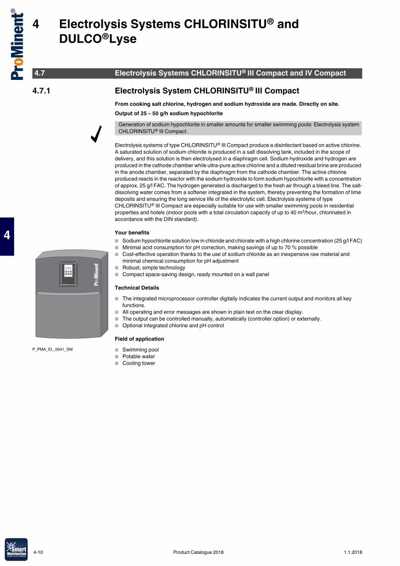
4 Electrolysis Systems CHLORINSITU® and DULCO®Lyse
4
4.7.1 Electrolysis System CHLORINSITU® III CompactFrom cooking salt chlorine, hydrogen and sodium hydroxide are made. Directly on site.Output of 25 – 50 g/h sodium hypochlorite
Electrolysis systems of type CHLORINSITU® III Compact produce a disinfectant based on active chlorine. A saturated solution of sodium chloride is produced in a salt dissolving tank, included in the scope of delivery, and this solution is then electrolysed in a diaphragm cell. Sodium hydroxide and hydrogen are produced in the cathode chamber while ultra-pure active chlorine and a diluted residual brine are produced in the anode chamber, separated by the diaphragm from the cathode chamber. The active chlorine produced reacts in the reactor with the sodium hydroxide to form sodium hypochlorite with a concentration of approx. 25 g/l FAC. The hydrogen generated is discharged to the fresh air through a bleed line. The salt-dissolving water comes from a softener integrated in the system, thereby preventing the formation of lime deposits and ensuring the long service life of the electrolytic cell. Electrolysis systems of type CHLORINSITU® III Compact are especially suitable for use with smaller swimming pools in residential properties and hotels (indoor pools with a total circulation capacity of up to 40 m3/hour, chlorinated in accordance with the DIN standard).
Your benefits� Sodium hypochlorite solution low in chloride and chlorate with a high chlorine concentration (25 g/l FAC)� Minimal acid consumption for pH correction, making savings of up to 70 % possible� Cost-effective operation thanks to the use of sodium chloride as an inexpensive raw material and
minimal chemical consumption for pH adjustment� Robust, simple technology� Compact space-saving design, ready mounted on a wall panel
Technical Details� The integrated microprocessor controller digitally indicates the current output and monitors all key
functions. � All operating and error messages are shown in plain text on the clear display. � The output can be controlled manually, automatically (controller option) or externally.� Optional integrated chlorine and pH control
Field of application� Swimming pool� Potable water� Cooling tower
4.7 Electrolysis Systems CHLORINSITU® III Compact and IV Compact
Generation of sodium hypochlorite in smaller amounts for smaller swimming pools: Electrolysis system CHLORINSITU® III Compact.
P_PMA_EL_0041_SW
4-10 Product Catalogue 2018 1.1.2018
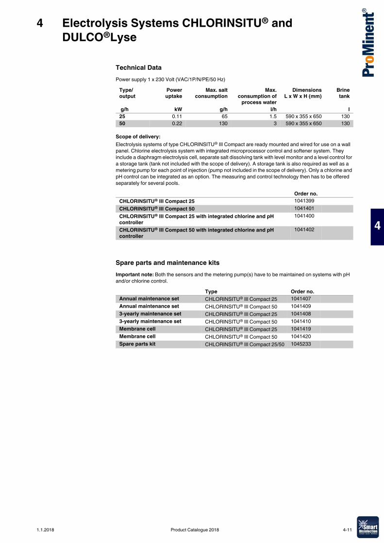
4 Electrolysis Systems CHLORINSITU® and DULCO®Lyse
4
Technical DataPower supply 1 x 230 Volt (VAC/1P/N/PE/50 Hz)
Scope of delivery:Electrolysis systems of type CHLORINSITU® III Compact are ready mounted and wired for use on a wall panel. Chlorine electrolysis system with integrated microprocessor control and softener system. They include a diaphragm electrolysis cell, separate salt dissolving tank with level monitor and a level control for a storage tank (tank not included with the scope of delivery). A storage tank is also required as well as a metering pump for each point of injection (pump not included in the scope of delivery). Only a chlorine and pH control can be integrated as an option. The measuring and control technology then has to be offered separately for several pools.
Spare parts and maintenance kitsImportant note: Both the sensors and the metering pump(s) have to be maintained on systems with pH and/or chlorine control.
Type/output
Poweruptake
Max. saltconsumption
Max.consumption of
process water
DimensionsL x W x H (mm)
Brinetank
g/h kW g/h l/h l25 0.11 65 1.5 590 x 355 x 650 13050 0.22 130 3 590 x 355 x 650 130
Order no.CHLORINSITU® III Compact 25 1041399CHLORINSITU® III Compact 50 1041401CHLORINSITU® III Compact 25 with integrated chlorine and pH controller
1041400
CHLORINSITU® III Compact 50 with integrated chlorine and pH controller
1041402
Type Order no.Annual maintenance set CHLORINSITU® III Compact 25 1041407Annual maintenance set CHLORINSITU® III Compact 50 10414093-yearly maintenance set CHLORINSITU® III Compact 25 10414083-yearly maintenance set CHLORINSITU® III Compact 50 1041410Membrane cell CHLORINSITU® III Compact 25 1041419Membrane cell CHLORINSITU® III Compact 50 1041420Spare parts kit CHLORINSITU® III Compact 25/50 1045233
1.1.2018 Product Catalogue 2018 4-11
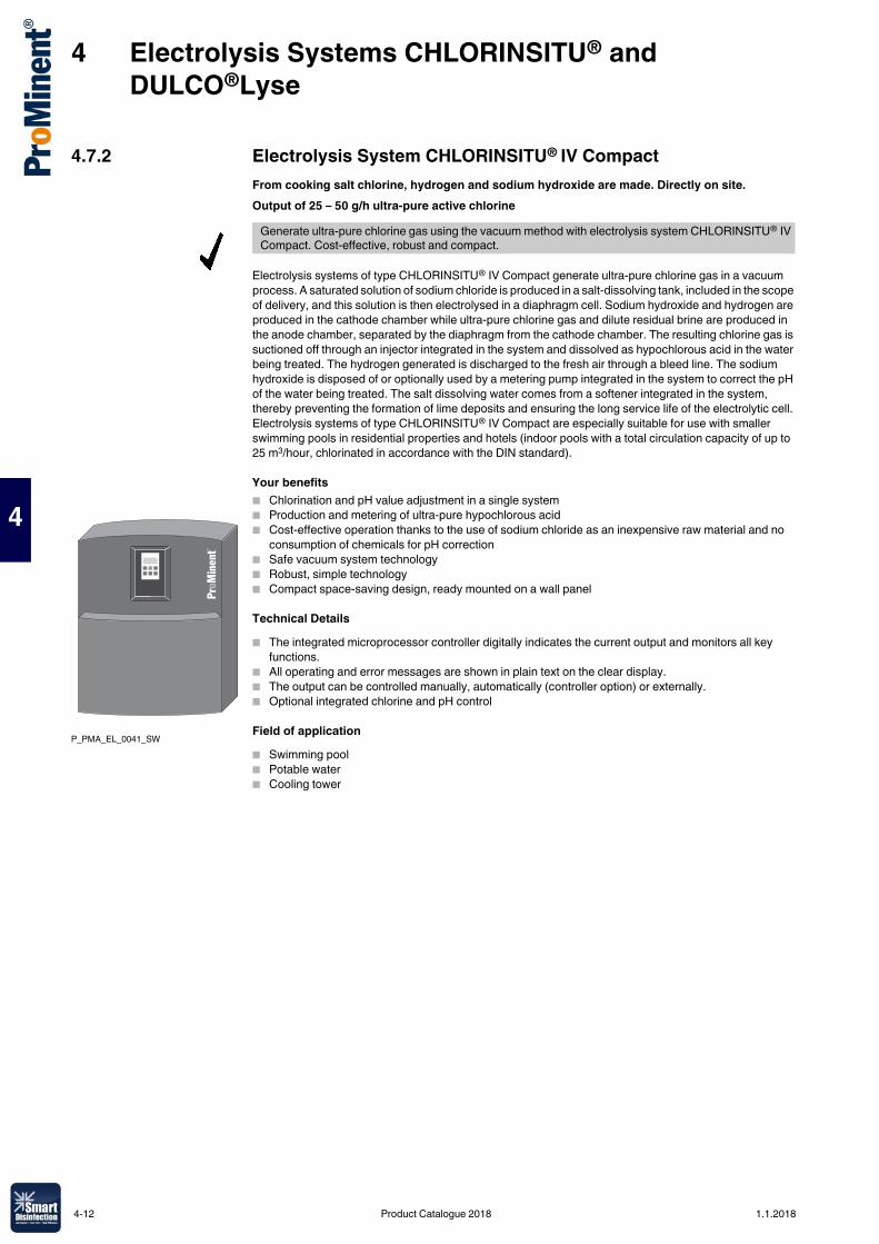
4 Electrolysis Systems CHLORINSITU® and DULCO®Lyse
4
4.7.2 Electrolysis System CHLORINSITU® IV CompactFrom cooking salt chlorine, hydrogen and sodium hydroxide are made. Directly on site.Output of 25 – 50 g/h ultra-pure active chlorine
Electrolysis systems of type CHLORINSITU® IV Compact generate ultra-pure chlorine gas in a vacuum process. A saturated solution of sodium chloride is produced in a salt-dissolving tank, included in the scope of delivery, and this solution is then electrolysed in a diaphragm cell. Sodium hydroxide and hydrogen are produced in the cathode chamber while ultra-pure chlorine gas and dilute residual brine are produced in the anode chamber, separated by the diaphragm from the cathode chamber. The resulting chlorine gas is suctioned off through an injector integrated in the system and dissolved as hypochlorous acid in the water being treated. The hydrogen generated is discharged to the fresh air through a bleed line. The sodium hydroxide is disposed of or optionally used by a metering pump integrated in the system to correct the pH of the water being treated. The salt dissolving water comes from a softener integrated in the system, thereby preventing the formation of lime deposits and ensuring the long service life of the electrolytic cell. Electrolysis systems of type CHLORINSITU® IV Compact are especially suitable for use with smaller swimming pools in residential properties and hotels (indoor pools with a total circulation capacity of up to 25 m3/hour, chlorinated in accordance with the DIN standard).
Your benefits� Chlorination and pH value adjustment in a single system� Production and metering of ultra-pure hypochlorous acid� Cost-effective operation thanks to the use of sodium chloride as an inexpensive raw material and no
consumption of chemicals for pH correction� Safe vacuum system technology� Robust, simple technology� Compact space-saving design, ready mounted on a wall panel
Technical Details� The integrated microprocessor controller digitally indicates the current output and monitors all key
functions. � All operating and error messages are shown in plain text on the clear display. � The output can be controlled manually, automatically (controller option) or externally.� Optional integrated chlorine and pH control
Field of application� Swimming pool� Potable water� Cooling tower
Generate ultra-pure chlorine gas using the vacuum method with electrolysis system CHLORINSITU® IV Compact. Cost-effective, robust and compact.
P_PMA_EL_0041_SW
4-12 Product Catalogue 2018 1.1.2018
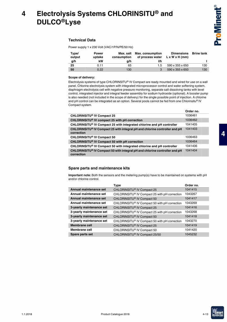
4 Electrolysis Systems CHLORINSITU® and DULCO®Lyse
4
Technical DataPower supply 1 x 230 Volt (VAC/1P/N/PE/50 Hz)
Scope of delivery:Electrolysis systems of type CHLORINSITU® IV Compact are ready mounted and wired for use on a wall panel. Chlorine electrolysis system with integrated microprocessor control and water softening system, diaphragm electrolysis cell with negative pressure monitoring, separate salt dissolving tanks with level control, integrated injector and integral feeder assembly for sodium hydroxide (optional). A booster pump is also needed (not included in the scope of delivery) for the single possible point of injection. A chlorine and pH control can be integrated as an option. Several pools cannot be fed from one Chlorinsitu® IV Compact system.
Spare parts and maintenance kitsImportant note: Both the sensors and the metering pump(s) have to be maintained on systems with pH and/or chlorine control.
Type/output
Poweruptake
Max. saltconsumption
Max. consumptionof process water
DimensionsL x W x H (mm)
Brine tank
g/h kW g/h l/h l25 0.11 65 1.5 590 x 355 x 650 13050 0.22 130 3 590 x 355 x 650 130
Order no.CHLORINSITU® IV Compact 25 1036461CHLORINSITU® IV compact 25 with pH correction 1036462CHLORINSITU® IV Compact 25 with integrated chlorine and pH controller 1041405CHLORINSITU® IV Compact 25 with integral pH and chlorine controller and pH correction
1041403
CHLORINSITU® IV Compact 50 1036463CHLORINSITU® IV Compact 50 with pH correction 1036464CHLORINSITU® IV Compact 50 with integrated chlorine and pH controller 1041406CHLORINSITU® IV Compact 50 with integral pH and chlorine controller and pH correction
1041404
Type Order no.Annual maintenance set CHLORINSITU® IV Compact 25 1041415Annual maintenance set CHLORINSITU® IV Compact 25 with pH correction 1043267Annual maintenance set CHLORINSITU® IV Compact 50 1041417Annual maintenance set CHLORINSITU® IV Compact 50 with pH correction 10432693-yearly maintenance set CHLORINSITU® IV Compact 25 10414163-yearly maintenance set CHLORINSITU® IV Compact 25 with pH correction 10432683-yearly maintenance set CHLORINSITU® IV Compact 50 10414183-yearly maintenance set CHLORINSITU® IV Compact 50 with pH correction 1043270Membrane cell CHLORINSITU® IV Compact 25 1041419Membrane cell CHLORINSITU® IV Compact 50 1041420Spare parts set CHLORINSITU® IV Compact 25/50 1045232
1.1.2018 Product Catalogue 2018 4-13

4 Electrolysis Systems CHLORINSITU® and DULCO®Lyse
4
From cooking salt chlorine, hydrogen and sodium hydroxide are made. Directly on site.Output of 100 – 3,500 g/h pure hypochlorous acid
Electrolysis systems of type CHLORINSITU® V generate pure chlorine gas in a vacuum process. A saturated solution of sodium chloride is produced in a salt-dissolving tank, included in the scope of delivery, and this solution is then electrolysed in a diaphragm cell. Chloride-free sodium hydroxide and hydrogen are produced in the cathode chamber, while ultra-pure chlorine gas and dilute residual brine are produced in the anode chamber, separated by the diaphragm from the cathode chamber. The chlorine gas produced is suctioned off through an injector (contained in the scope of delivery) and fully dissolved as hypochlorous acid in the water being treated (through a bypass). The superchlorinated water is then distributed throughout the various pools via one or more proportionately controllable motor driven ball valves. The vacuum is kept stable by a single frequency-controlled booster pump. This permits significant savings in terms of energy. The chloride-free sodium hydroxide is stored temporarily and can be used for pH value correction. A standard diaphragm metering pump is first used to correct the base (pH 6.8 – 7) of the superchlorinated water. The fine correction of the pH value is provided via additional alkali metering pumps for each circuit or point of injection. The hydrogen produced is diluted with fresh air through an ATEX 95-approved fan and discharged safely. The diluted residual brine is fully discarded. To achieve this, the diluted brine is strongly diluted with softened water, neutralised by the addition of sodium hydroxide and disposed of in the sewer. All residual chloride and chlorate are thus disposed of and are not mixed with the process water. Electrolysis systems of type CHLORINSITU® V can thus be compared with pure chlorine gas in terms of their oxidation strength and chloride / chlorate content in the process water. The salt-dissolving water comes from a softener integrated in the system, preventing the formation of lime deposits and ensuring the long service life of the diaphragm cell. The efficiency of electrolysis is constantly monitored by various flow meters, the addition of water depending on the sodium hydroxide production and the base pH correction.
Your benefits� Chlorination and pH adjustment with a single system� Exceedingly low chloride and chlorate content� Production and metering of high-purity hypochlorous acid without temporary storage� Safe system control with remote diagnosis by Remote Control Engineer� Excellent service life of the membrane cells, thanks to a constant vacuum� A frequency-controlled circulation pump maintains the vacuum constant in the enclosed anode area� Maximum operating safety due to their design as negative pressure systems� Active process control of production by largely internal measuring and control technology� Cost-effective operation thanks to the use of sodium chloride as an inexpensive raw material and no
consumption of chemicals for pH correction� Complete disposal of the diluted brine, nothing is fed back into the process water being treated� Comparable with pure chlorine gas in terms of oxidation strength and chloride / chlorate content in the
process water� Robust technology� Compact, space-saving design
Technical Details� Modern PLC with large illuminated display� Integrated Remote Control Engineer for remote diagnosis and troubleshooting� Chlorine metering and pH value correction controlled via contact inputs� Analogue input (optional)� MODBUS or PROFIBUS® (optional)� Several points of injection (optional)� Multiple booster pumps (optional) can be used for different water qualities (e.g. brine and freshwater
pools)
Field of application� Potable water� Waste water� Process water� Swimming pool water� Cooling tower
4.8 Electrolysis System CHLORINSITU® V
Ultra-pure active chlorine gas is generated in a vacuum process using the electrolysis system CHLORINSITU® V. Suited to applications for metering hypochlorous acid and simultaneously correcting the pH value.
P_PMA_EL_0013_SW
4-14 Product Catalogue 2018 1.1.2018
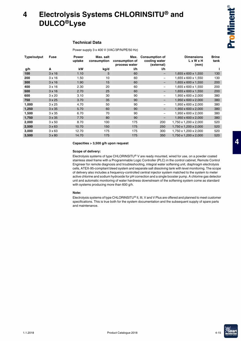
4 Electrolysis Systems CHLORINSITU® and DULCO®Lyse
4
Technical DataPower supply 3 x 400 V (VAC/3P/N/PE/50 Hz)
Capacities > 3,500 g/h upon request
Scope of delivery:Electrolysis systems of type CHLORINSITU® V are ready mounted, wired for use, on a powder coated stainless steel frame with a Programmable Logic Controller (PLC) in the control cabinet, Remote Control Engineer for remote diagnosis and troubleshooting, integral water softening unit, diaphragm electrolysis cells, ATEX-95-compliant bleed system and separate salt dissolving tank with level monitoring. The scope of delivery also includes a frequency-controlled central injector system matched to the system to meter active chlorine and sodium hydroxide for pH correction and a single booster pump. A chlorine gas detector unit and automatic monitoring of water hardness downstream of the softening system come as standard with systems producing more than 600 g/h.
Note:Electrolysis systems of type CHLORINSITU® II, III, V and V Plus are offered and planned to meet customer specifications. This is true both for the system documentation and the subsequent supply of spare parts and maintenance.
Type/output Fuse Poweruptake
Max. saltconsumption
Max.consumption of
process water
Consumption ofcooling water
(external)
DimensionsL x W x H
(mm)
Brinetank
g/h A kW kg/d l/h l/h l100 3 x 16 1.10 5 60 – 1,655 x 600 x 1,550 130200 3 x 16 1.50 10 60 – 1,655 x 600 x 1,550 130300 3 x 16 1.90 15 60 – 1,655 x 600 x 1,550 200400 3 x 16 2.30 20 60 – 1,655 x 600 x 1,550 200500 3 x 16 2.70 25 60 – 1,655 x 600 x 1,550 200600 3 x 20 3.10 30 90 – 1,950 x 600 x 2,000 380750 3 x 25 3.70 35 90 – 1,950 x 600 x 2,000 3801,000 3 x 25 4.70 50 90 – 1,950 x 600 x 2,000 3801,250 3 x 35 5.70 60 90 – 1,950 x 600 x 2,000 3801,500 3 x 35 6.70 70 90 – 1,950 x 600 x 2,000 3801,750 3 x 35 7.70 80 90 – 1,950 x 600 x 2,000 3802,000 3 x 50 8.70 100 175 200 1,750 x 1,200 x 2,000 5202,500 3 x 63 10.70 150 175 250 1,750 x 1,200 x 2,000 5203,000 3 x 63 12.70 175 175 300 1,750 x 1,200 x 2,000 5203,500 3 x 80 14.70 175 175 350 1,750 x 1,200 x 2,000 520
1.1.2018 Product Catalogue 2018 4-15
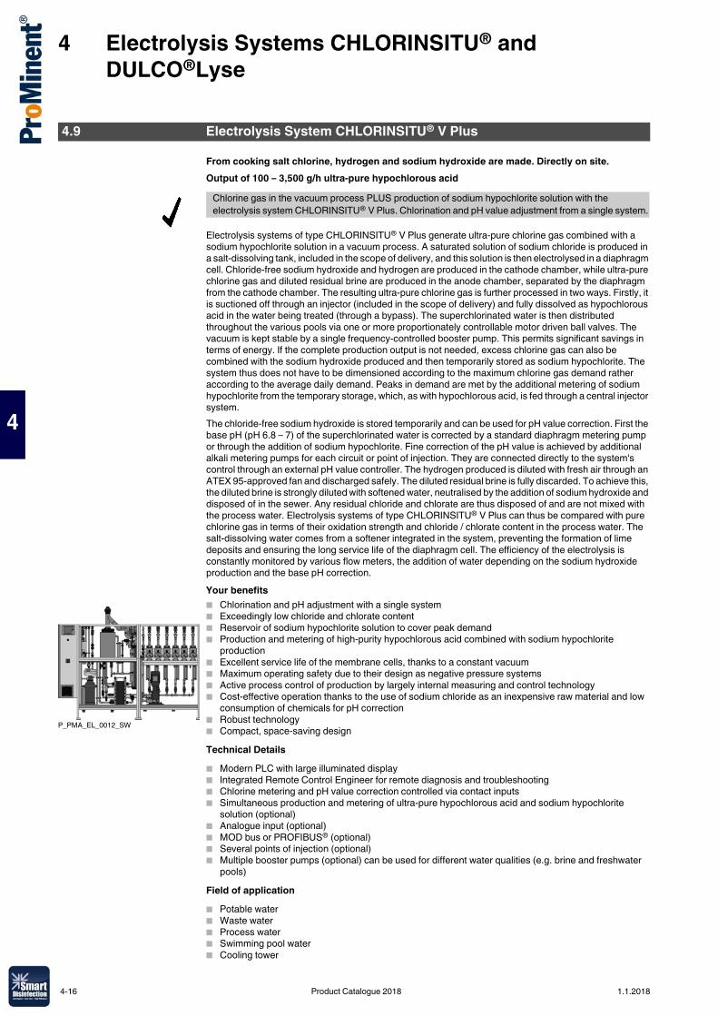
4 Electrolysis Systems CHLORINSITU® and DULCO®Lyse
4
From cooking salt chlorine, hydrogen and sodium hydroxide are made. Directly on site.Output of 100 – 3,500 g/h ultra-pure hypochlorous acid
Electrolysis systems of type CHLORINSITU® V Plus generate ultra-pure chlorine gas combined with a sodium hypochlorite solution in a vacuum process. A saturated solution of sodium chloride is produced in a salt-dissolving tank, included in the scope of delivery, and this solution is then electrolysed in a diaphragm cell. Chloride-free sodium hydroxide and hydrogen are produced in the cathode chamber, while ultra-pure chlorine gas and diluted residual brine are produced in the anode chamber, separated by the diaphragm from the cathode chamber. The resulting ultra-pure chlorine gas is further processed in two ways. Firstly, it is suctioned off through an injector (included in the scope of delivery) and fully dissolved as hypochlorous acid in the water being treated (through a bypass). The superchlorinated water is then distributed throughout the various pools via one or more proportionately controllable motor driven ball valves. The vacuum is kept stable by a single frequency-controlled booster pump. This permits significant savings in terms of energy. If the complete production output is not needed, excess chlorine gas can also be combined with the sodium hydroxide produced and then temporarily stored as sodium hypochlorite. The system thus does not have to be dimensioned according to the maximum chlorine gas demand rather according to the average daily demand. Peaks in demand are met by the additional metering of sodium hypochlorite from the temporary storage, which, as with hypochlorous acid, is fed through a central injector system.The chloride-free sodium hydroxide is stored temporarily and can be used for pH value correction. First the base pH (pH 6.8 – 7) of the superchlorinated water is corrected by a standard diaphragm metering pump or through the addition of sodium hypochlorite. Fine correction of the pH value is achieved by additional alkali metering pumps for each circuit or point of injection. They are connected directly to the system's control through an external pH value controller. The hydrogen produced is diluted with fresh air through an ATEX 95-approved fan and discharged safely. The diluted residual brine is fully discarded. To achieve this, the diluted brine is strongly diluted with softened water, neutralised by the addition of sodium hydroxide and disposed of in the sewer. Any residual chloride and chlorate are thus disposed of and are not mixed with the process water. Electrolysis systems of type CHLORINSITU® V Plus can thus be compared with pure chlorine gas in terms of their oxidation strength and chloride / chlorate content in the process water. The salt-dissolving water comes from a softener integrated in the system, preventing the formation of lime deposits and ensuring the long service life of the diaphragm cell. The efficiency of the electrolysis is constantly monitored by various flow meters, the addition of water depending on the sodium hydroxide production and the base pH correction.Your benefits� Chlorination and pH adjustment with a single system� Exceedingly low chloride and chlorate content� Reservoir of sodium hypochlorite solution to cover peak demand� Production and metering of high-purity hypochlorous acid combined with sodium hypochlorite
production� Excellent service life of the membrane cells, thanks to a constant vacuum� Maximum operating safety due to their design as negative pressure systems� Active process control of production by largely internal measuring and control technology� Cost-effective operation thanks to the use of sodium chloride as an inexpensive raw material and low
consumption of chemicals for pH correction� Robust technology� Compact, space-saving designTechnical Details� Modern PLC with large illuminated display� Integrated Remote Control Engineer for remote diagnosis and troubleshooting� Chlorine metering and pH value correction controlled via contact inputs� Simultaneous production and metering of ultra-pure hypochlorous acid and sodium hypochlorite
solution (optional)� Analogue input (optional)� MOD bus or PROFIBUS® (optional)� Several points of injection (optional)� Multiple booster pumps (optional) can be used for different water qualities (e.g. brine and freshwater
pools)Field of application� Potable water� Waste water� Process water� Swimming pool water� Cooling tower
4.9 Electrolysis System CHLORINSITU® V Plus
Chlorine gas in the vacuum process PLUS production of sodium hypochlorite solution with the electrolysis system CHLORINSITU® V Plus. Chlorination and pH value adjustment from a single system.
P_PMA_EL_0012_SW
4-16 Product Catalogue 2018 1.1.2018
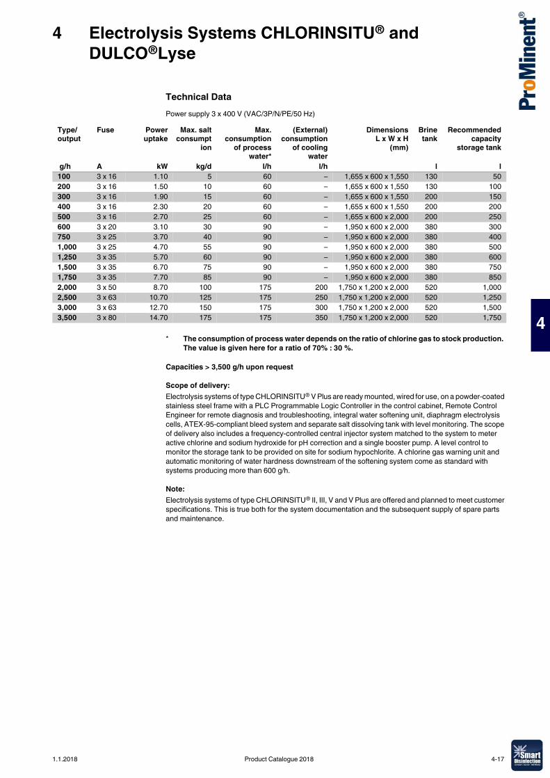
4 Electrolysis Systems CHLORINSITU® and DULCO®Lyse
4
Technical DataPower supply 3 x 400 V (VAC/3P/N/PE/50 Hz)
Capacities > 3,500 g/h upon request
Scope of delivery:Electrolysis systems of type CHLORINSITU® V Plus are ready mounted, wired for use, on a powder-coated stainless steel frame with a PLC Programmable Logic Controller in the control cabinet, Remote Control Engineer for remote diagnosis and troubleshooting, integral water softening unit, diaphragm electrolysis cells, ATEX-95-compliant bleed system and separate salt dissolving tank with level monitoring. The scope of delivery also includes a frequency-controlled central injector system matched to the system to meter active chlorine and sodium hydroxide for pH correction and a single booster pump. A level control to monitor the storage tank to be provided on site for sodium hypochlorite. A chlorine gas warning unit and automatic monitoring of water hardness downstream of the softening system come as standard with systems producing more than 600 g/h.
Note:Electrolysis systems of type CHLORINSITU® II, III, V and V Plus are offered and planned to meet customer specifications. This is true both for the system documentation and the subsequent supply of spare parts and maintenance.
Type/output
Fuse Poweruptake
Max. saltconsumpt
ion
Max.consumption
of processwater*
(External)consumption
of coolingwater
DimensionsL x W x H
(mm)
Brinetank
Recommendedcapacity
storage tank
g/h A kW kg/d l/h l/h l l100 3 x 16 1.10 5 60 – 1,655 x 600 x 1,550 130 50200 3 x 16 1.50 10 60 – 1,655 x 600 x 1,550 130 100300 3 x 16 1.90 15 60 – 1,655 x 600 x 1,550 200 150400 3 x 16 2.30 20 60 – 1,655 x 600 x 1,550 200 200500 3 x 16 2.70 25 60 – 1,655 x 600 x 2,000 200 250600 3 x 20 3.10 30 90 – 1,950 x 600 x 2,000 380 300750 3 x 25 3.70 40 90 – 1,950 x 600 x 2,000 380 4001,000 3 x 25 4.70 55 90 – 1,950 x 600 x 2,000 380 5001,250 3 x 35 5.70 60 90 – 1,950 x 600 x 2,000 380 6001,500 3 x 35 6.70 75 90 – 1,950 x 600 x 2,000 380 7501,750 3 x 35 7.70 85 90 – 1,950 x 600 x 2,000 380 8502,000 3 x 50 8.70 100 175 200 1,750 x 1,200 x 2,000 520 1,0002,500 3 x 63 10.70 125 175 250 1,750 x 1,200 x 2,000 520 1,2503,000 3 x 63 12.70 150 175 300 1,750 x 1,200 x 2,000 520 1,5003,500 3 x 80 14.70 175 175 350 1,750 x 1,200 x 2,000 520 1,750
* The consumption of process water depends on the ratio of chlorine gas to stock production. The value is given here for a ratio of 70% : 30 %.
1.1.2018 Product Catalogue 2018 4-17
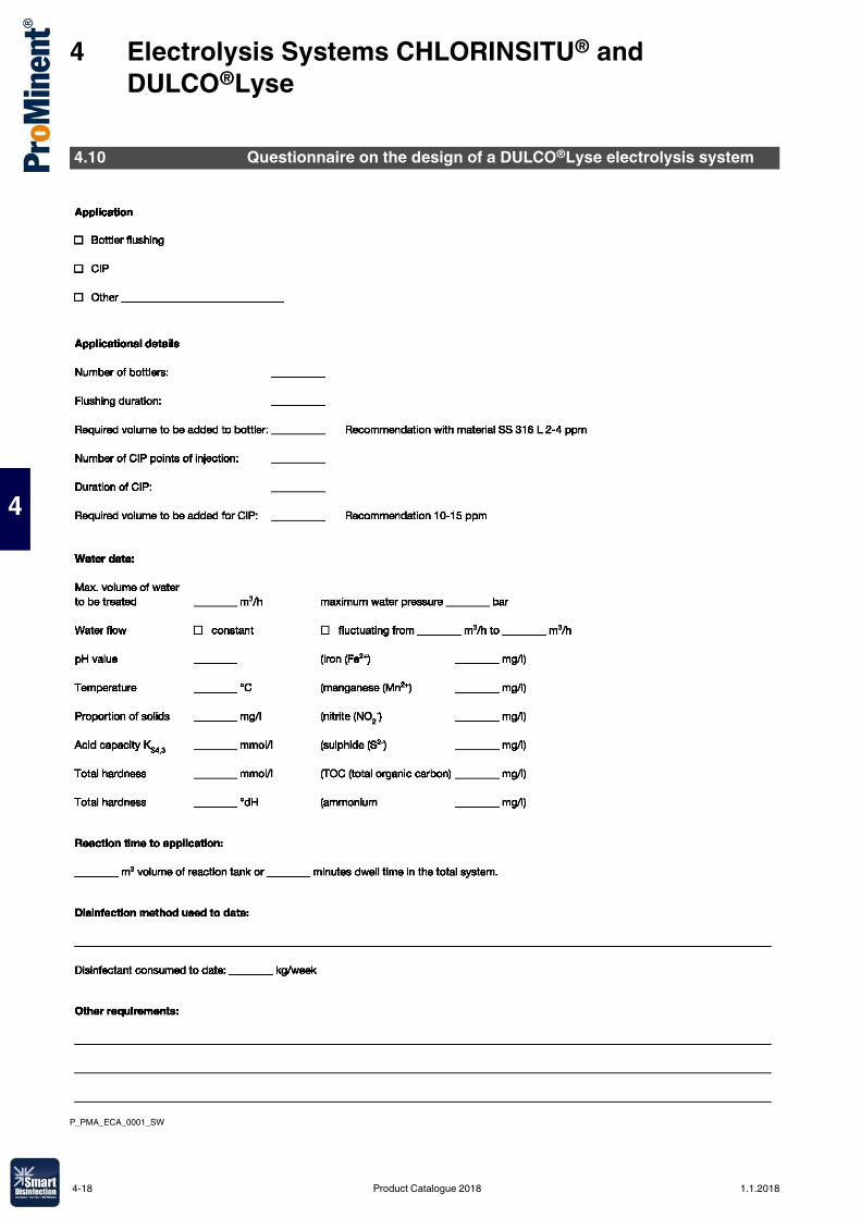
4 Electrolysis Systems CHLORINSITU® and DULCO®Lyse
4
P_PMA_ECA_0001_SW
4.10 Questionnaire on the design of a DULCO®Lyse electrolysis system
4-18 Product Catalogue 2018 1.1.2018
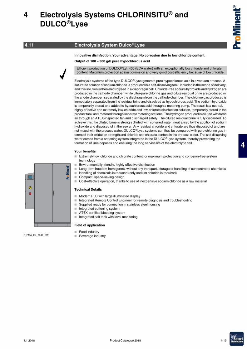
4 Electrolysis Systems CHLORINSITU® and DULCO®Lyse
4
Innovative disinfection. Your advantage: No corrosion due to low chloride content.Output of 100 – 300 g/h pure hypochlorous acid
Electrolysis systems of the type DULCO®Lyse generate pure hypochlorous acid in a vacuum process. A saturated solution of sodium chloride is produced in a salt-dissolving tank, included in the scope of delivery, and this solution is then electrolysed in a diaphragm cell. Chloride-free sodium hydroxide and hydrogen are produced in the cathode chamber, while ultra-pure chlorine gas and dilute residual brine are produced in the anode chamber, separated by the diaphragm from the cathode chamber. The chlorine gas produced is immediately separated from the residual brine and dissolved as hypochlorous acid. The sodium hydroxide is temporarily stored and added to hypochlorous acid through a metering pump. The result is a neutral, highly effective and extremely low-chloride and low-chlorate disinfection solution, temporarily stored in the product tank until metered through separate metering stations. The hydrogen produced is diluted with fresh air through an ATEX-inspected fan and discharged safely. The diluted residual brine is fully discarded. To achieve this, the diluted brine is strongly diluted with softened water, neutralised by the addition of sodium hydroxide and disposed of in the sewer. Any residual chloride and chlorate are thus disposed of and are not mixed with the process water. DULCO®Lyse systems can thus be compared with pure chlorine gas in terms of their oxidation strength and chloride and chlorate content in the process water. The salt dissolving water comes from a softening system integrated in the DULCO®Lyse system, thereby preventing the formation of lime deposits and ensuring the long service life of the electrolytic cell.
Your benefits� Extremely low chloride and chlorate content for maximum protection and corrosion-free system
technology� Environmentally friendly, highly effective disinfection� Long-term freedom from germs, without any transport, storage or handling of concentrated chemicals� Handling of chemicals is reduced (only sodium chloride is required)� Compact, space-saving design� Cost-effective operation, thanks to use of inexpensive sodium chloride as a raw material
Technical Details� Modern PLC with large illuminated display� Integrated Remote Control Engineer for remote diagnosis and troubleshooting� Supplied ready for connection in stainless steel housing� Integrated softening system� ATEX-certified bleeding system� Integrated salt tank with level monitoring
Field of application� Food industry� Beverage industry
4.11 Electrolysis System Dulco®Lyse
Efficient production of DULCO®Lyt 400 (ECA water) with an exceptionally low chloride and chlorate content. Maximum protection against corrosion and very good cost efficiency because of low chloride.
P_PMA_EL_0042_SW
1.1.2018 Product Catalogue 2018 4-19
4 Electrolysis Systems CHLORINSITU® and DULCO®Lyse
4
Technical DataPower supply: 1 x 230 Volt (V AC/1P/N/PE/50 Hz)Dimensions (H x W x D): 2,100 x 1,250 x 610 mm
Scope of delivery:DULCO®Lyse electrolysis systems are assembled ready-wired in a sealed stainless steel or open cabinet� PLC (Programmable Logic Controller) in the attached control cabinet� Integrated softening system� Electrolysis cell(s)� ATEX-certified bleeding system� Integrated salt dissolving tank with level monitoring� Ultrasound level probe for the DULCO®Lyt product tank� Piping between the salt-dissolving storage tank and DULCO®Lyse system� 25 kg salt for commissioning� Hardness control measuring device� pH4 + pH7buffer solution
Material not included in the scope of delivery:� Sodium hydroxide (33 % needed for commissioning)� DULCO®Lyt product tank� DULCO®Lyt metering station� Piping outside of the DULCO®Lyse
Spare parts and maintenance kits
Type/output
DULCO®Lyt productionat 400 ppm
Poweruptake
Salt solution tankvolume
Cabinet Order no.
g/h l/h kW lDULCO®Lyse 100 100 250 1.10 200 stainless steel
cabinet1041424
DULCO®Lyse 100 100 250 1.10 200 open cabinet 1062093DULCO®Lyse 200 200 500 1.50 200 stainless steel
cabinet1043987
DULCO®Lyse 200 200 500 1.50 200 open cabinet 1062104DULCO®Lyse 300 300 750 1.90 200 stainless steel
cabinet1043988
DULCO®Lyse 300 300 750 1.90 200 open cabinet 1062135
Type Order no.Annual maintenance kit DULCO®Lyse 100 – 300 10414273-yearly maintenance kit DULCO®Lyse 100 – 300 1041430Spare parts kit DULCO®Lyse 100 – 300 1044366
4-20 Product Catalogue 2018 1.1.2018
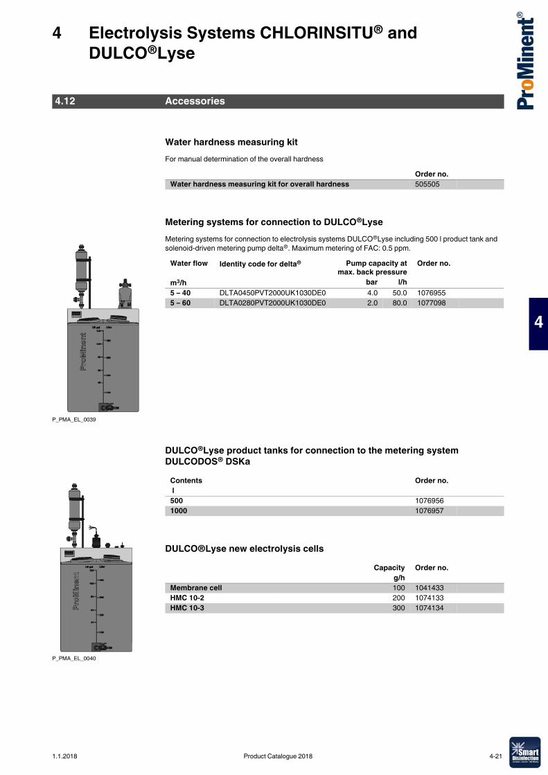
4 Electrolysis Systems CHLORINSITU® and DULCO®Lyse
4
Water hardness measuring kitFor manual determination of the overall hardness
Metering systems for connection to DULCO®LyseMetering systems for connection to electrolysis systems DULCO®Lyse including 500 l product tank and solenoid-driven metering pump delta®. Maximum metering of FAC: 0.5 ppm.
DULCO®Lyse product tanks for connection to the metering system DULCODOS® DSKa
DULCO®Lyse new electrolysis cells
4.12 Accessories
Order no.Water hardness measuring kit for overall hardness 505505
P_PMA_EL_0039
Water flow Identity code for delta® Pump capacity atmax. back pressure
Order no.
m3/h bar l/h5 – 40 DLTA0450PVT2000UK1030DE0 4.0 50.0 10769555 – 60 DLTA0280PVT2000UK1030DE0 2.0 80.0 1077098
P_PMA_EL_0040
Contents Order no. l500 10769561000 1076957
Capacity Order no.g/h
Membrane cell 100 1041433HMC 10-2 200 1074133HMC 10-3 300 1074134
1.1.2018 Product Catalogue 2018 4-21
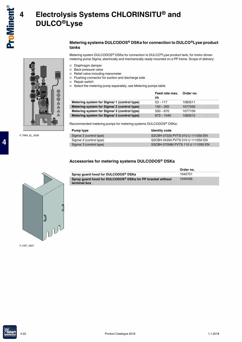
4 Electrolysis Systems CHLORINSITU® and DULCO®Lyse
4
Metering systems DULCODOS® DSKa for connection to DULCO®Lyse product tanksMetering system DULCODOS® DSKa for connection to DULCO®Lyse product tank, for motor-driven metering pump Sigma, electrically and mechanically ready mounted on a PP frame. Scope of delivery:� Diaphragm damper� Back pressure valve� Relief valve including manometer� Flushing connector for suction and discharge side� Repair switch� Select the metering pump separately, see Metering pumps table
Recommended metering pumps for metering systems DULCODOS® DSKa:
Accessories for metering systems DULCODOS® DSKa
P_PMA_EL_0038
Feed rate max. Order no.l/h
Metering system for Sigma/ 1 (control type) 53 – 117 1083511Metering system for Sigma/ 2 (control type) 150 – 350 1077030Metering system for Sigma/ 3 (control type) 500 – 670 1077109Metering system for Sigma/ 3 (control type) 670 – 1040 1083512
Pump type Identity codeSigma/ 2 (control type) S2CBH 07220 PVTS 010 U 1110S0 ENSigma/ 2 (control type) S2CBH 04350 PVTS 010 U 1110S0 ENSigma/ 3 (control type) S3CBH 070580 PVTS 110 U 1110S0 EN
P_DST_0007
Order no.Spray guard hood for DULCODOS® DSKa 1042751Spray guard hood for DULCODOS® DSKa for PP bracket without terminal box
1040456
4-22 Product Catalogue 2018 1.1.2018
5 Chlorine Gas Metering Systems DULCO®Vaq
5
5.0.1Product Catalogue 2018
Chlorine gas metering systems are used in water treatment for disinfection and oxidation. They prevent and/or reduce the growth of micro-organisms.The safety of users is the priority. This is essentially guaranteed by vacuum operation directly from the chlorine gas tank and downstream of the evaporator. This ensures that the escape of chlorine gas can be prevented even in the event of a ruptured pipe.All the components are perfectly coordinated to each other and ensure seamless operation. With higher demand, several storage tanks can be combined using manifolds. Uninterrupted chlorine gas supply can be ensured by the use of an automatic vacuum switch.Chlorine gas stands out on account of its high bacteria destruction speed coupled with low operating costs. Due to the high level of reactivity, sensible handling and compliance with common safety regulations (e.g. DIN 19606, BGV D5 / DGUV-V 50, BGR/GUV-R 108 and other regional regulations) is imperative.No by-products are metered by the use of pure chlorine gas and thus the water quality is maintained. Furthermore, chlorine gas can be stored as required without forming decomposition products.Chlorine is a pungent smelling yellow/green gas in its normal state. The density is ~3.2 kg/m3, thus chlorine gas is heavier than air. Chlorine is supplied in liquid form and changes to its gaseous state during extraction caused by reduced pressure. The vacuum generated by an injector draws the chlorine gas by suction to the point of injection. The chlorine gas is dissolved in water and produces hypochlorous acid responsible for disinfection.Make sure that only a technical expert carries out commissioning, maintenance and repair. Compliance with national and regional regulations is mandatory.
5.1.1 Chlorine Gas Metering Systems DULCO®VaqChlorine is reliably handled under vacuum in the metering system DULCO®Vaq. The vacuum generated in the injector opens the vacuum metering controller fitted on the chlorine gas tank and the chlorine gas enters the water to be treated. Adjustment valves control the metering volume and flow meters precisely indicate the chlorine gas flow. A large number of individual configurations is provided for by additional components, such as motorised control valves, injectors or vacuum switches.ProMinent specialists take into account all the technical safety-related requirements in the design of the chlorine gas metering system.
5.1 General Information on Chlorine Gas Metering Systems
1.1.2018 Product Catalogue 2018 5-1
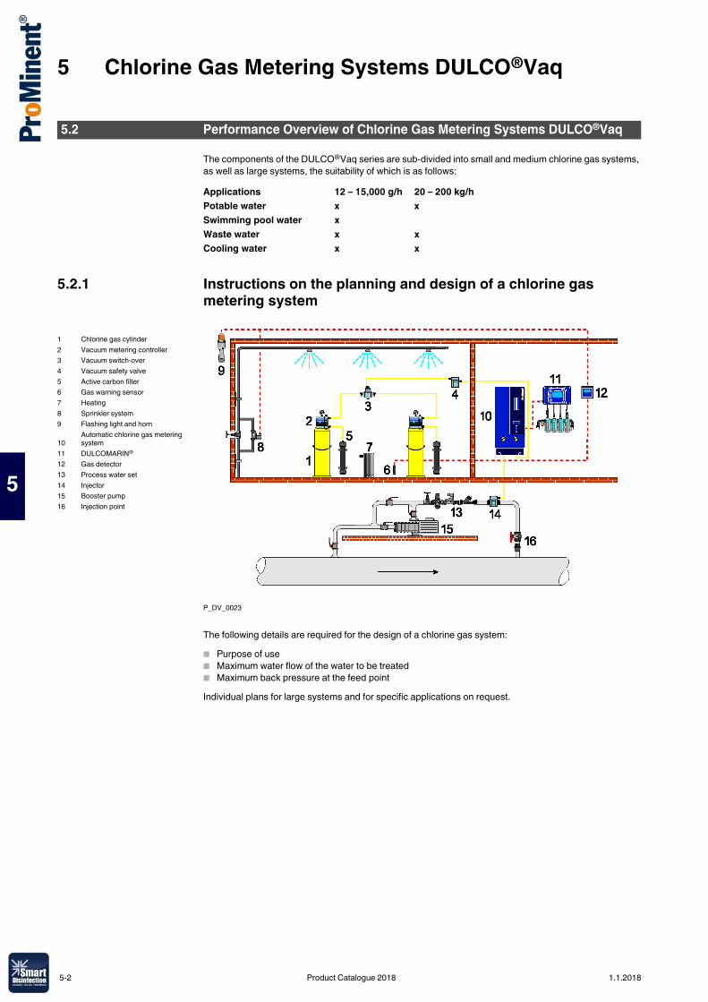
5 Chlorine Gas Metering Systems DULCO®Vaq
5
The components of the DULCO®Vaq series are sub-divided into small and medium chlorine gas systems, as well as large systems, the suitability of which is as follows:
5.2.1 Instructions on the planning and design of a chlorine gas metering system
P_DV_0023
The following details are required for the design of a chlorine gas system:� Purpose of use� Maximum water flow of the water to be treated� Maximum back pressure at the feed pointIndividual plans for large systems and for specific applications on request.
5.2 Performance Overview of Chlorine Gas Metering Systems DULCO®Vaq
Applications 12 – 15,000 g/h 20 – 200 kg/hPotable water x xSwimming pool water xWaste water x xCooling water x x
1 Chlorine gas cylinder2 Vacuum metering controller3 Vacuum switch-over4 Vacuum safety valve5 Active carbon filter6 Gas warning sensor7 Heating8 Sprinkler system9 Flashing light and horn
10Automatic chlorine gas metering system
11 DULCOMARIN®
12 Gas detector13 Process water set14 Injector15 Booster pump16 Injection point
5-2 Product Catalogue 2018 1.1.2018
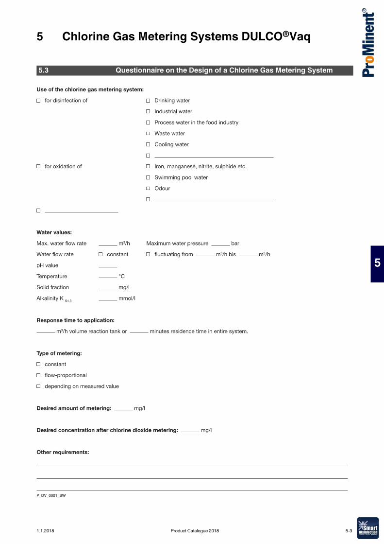
5 Chlorine Gas Metering Systems DULCO®Vaq
5
P_DV_0001_SW
5.3 Questionnaire on the Design of a Chlorine Gas Metering System
Use of the chlorine gas metering system:
for disinfection of Drinking water
Industrial water
Process water in the food industry
Waste water
Cooling water
for oxidation of Iron, manganese, nitrite, sulphide etc.
Swimming pool water
Odour
Water values:
m3/h Maximum water pressure bar
constant m3/h bis m3/h
pH value
Temperature °C
Solid fraction mg/l
Alkalinity K S4,3 mmol/l
Response time to application:
m3/h volume reaction tank or minutes residence time in entire system.
Type of metering:
constant
depending on measured value
Desired amount of metering: mg/l
Desired concentration after chlorine dioxide metering: mg/l
Other requirements:
1.1.2018 Product Catalogue 2018 5-3
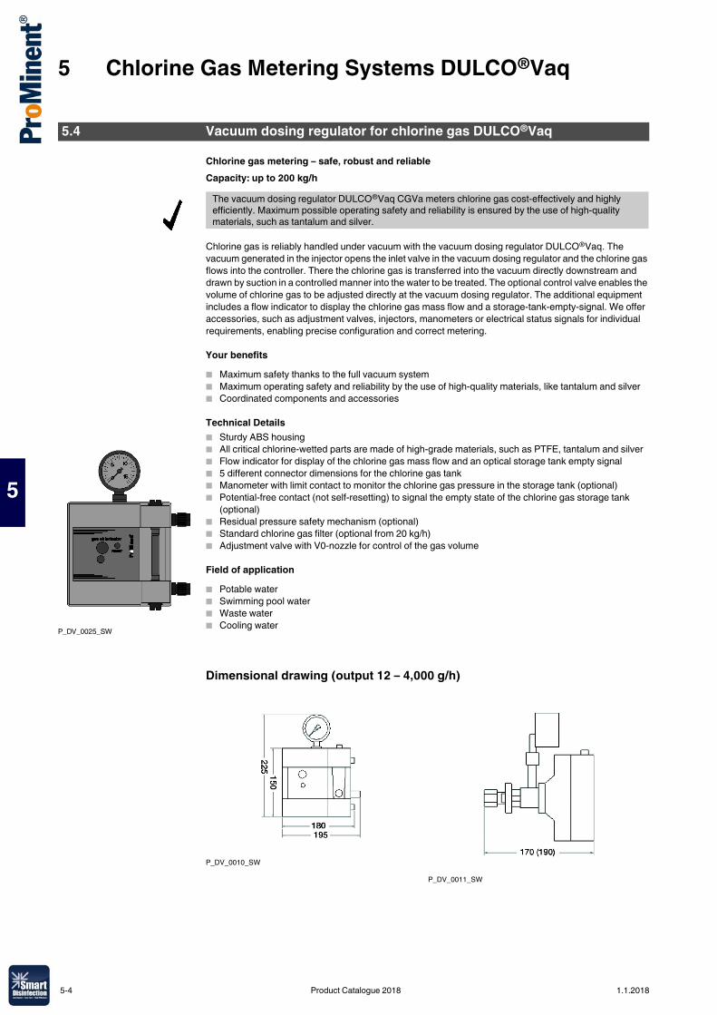
5 Chlorine Gas Metering Systems DULCO®Vaq
5
Chlorine gas metering – safe, robust and reliableCapacity: up to 200 kg/h
Chlorine gas is reliably handled under vacuum with the vacuum dosing regulator DULCO®Vaq. The vacuum generated in the injector opens the inlet valve in the vacuum dosing regulator and the chlorine gas flows into the controller. There the chlorine gas is transferred into the vacuum directly downstream and drawn by suction in a controlled manner into the water to be treated. The optional control valve enables the volume of chlorine gas to be adjusted directly at the vacuum dosing regulator. The additional equipment includes a flow indicator to display the chlorine gas mass flow and a storage-tank-empty-signal. We offer accessories, such as adjustment valves, injectors, manometers or electrical status signals for individual requirements, enabling precise configuration and correct metering.
Your benefits� Maximum safety thanks to the full vacuum system� Maximum operating safety and reliability by the use of high-quality materials, like tantalum and silver� Coordinated components and accessories
Technical Details� Sturdy ABS housing� All critical chlorine-wetted parts are made of high-grade materials, such as PTFE, tantalum and silver� Flow indicator for display of the chlorine gas mass flow and an optical storage tank empty signal� 5 different connector dimensions for the chlorine gas tank� Manometer with limit contact to monitor the chlorine gas pressure in the storage tank (optional)� Potential-free contact (not self-resetting) to signal the empty state of the chlorine gas storage tank
(optional)� Residual pressure safety mechanism (optional)� Standard chlorine gas filter (optional from 20 kg/h)� Adjustment valve with V0-nozzle for control of the gas volume
Field of application� Potable water� Swimming pool water� Waste water� Cooling water
Dimensional drawing (output 12 – 4,000 g/h)
5.4 Vacuum dosing regulator for chlorine gas DULCO®Vaq
The vacuum dosing regulator DULCO®Vaq CGVa meters chlorine gas cost-effectively and highly efficiently. Maximum possible operating safety and reliability is ensured by the use of high-quality materials, such as tantalum and silver.
P_DV_0025_SW
P_DV_0010_SW
P_DV_0011_SW
5-4 Product Catalogue 2018 1.1.2018
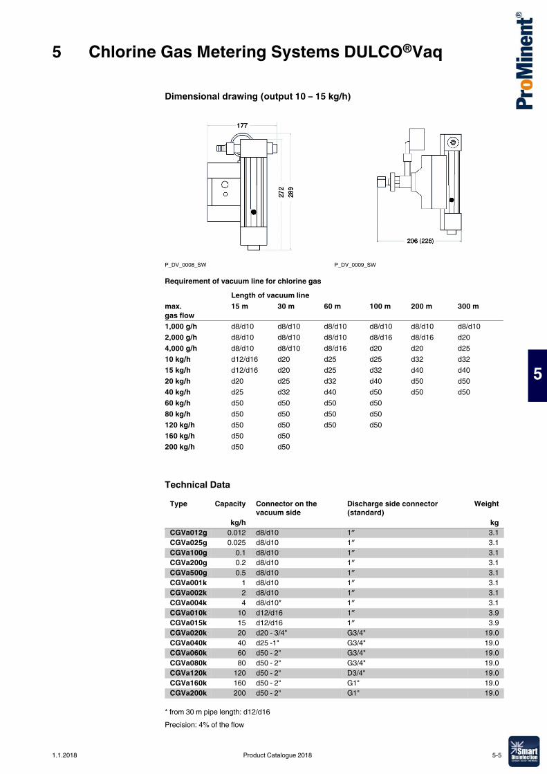
5 Chlorine Gas Metering Systems DULCO®Vaq
5
Dimensional drawing (output 10 – 15 kg/h)
Requirement of vacuum line for chlorine gas
Technical Data
* from 30 m pipe length: d12/d16Precision: 4% of the flow
P_DV_0008_SW P_DV_0009_SW
Length of vacuum linemax. gas flow
15 m 30 m 60 m 100 m 200 m 300 m
1,000 g/h d8/d10 d8/d10 d8/d10 d8/d10 d8/d10 d8/d102,000 g/h d8/d10 d8/d10 d8/d10 d8/d16 d8/d16 d204,000 g/h d8/d10 d8/d10 d8/d16 d20 d20 d2510 kg/h d12/d16 d20 d25 d25 d32 d3215 kg/h d12/d16 d20 d25 d32 d40 d4020 kg/h d20 d25 d32 d40 d50 d5040 kg/h d25 d32 d40 d50 d50 d5060 kg/h d50 d50 d50 d5080 kg/h d50 d50 d50 d50120 kg/h d50 d50 d50 d50160 kg/h d50 d50200 kg/h d50 d50
Type Capacity Connector on the vacuum side
Discharge side connector (standard)
Weight
kg/h kgCGVa012g 0.012 d8/d10 1″ 3.1CGVa025g 0.025 d8/d10 1″ 3.1CGVa100g 0.1 d8/d10 1″ 3.1CGVa200g 0.2 d8/d10 1″ 3.1CGVa500g 0.5 d8/d10 1″ 3.1CGVa001k 1 d8/d10 1″ 3.1CGVa002k 2 d8/d10 1″ 3.1CGVa004k 4 d8/d10* 1″ 3.1CGVa010k 10 d12/d16 1″ 3.9CGVa015k 15 d12/d16 1″ 3.9CGVa020k 20 d20 - 3/4" G3/4" 19.0CGVa040k 40 d25 -1" G3/4" 19.0CGVa060k 60 d50 - 2" G3/4" 19.0CGVa080k 80 d50 - 2" G3/4" 19.0CGVa120k 120 d50 - 2" D3/4" 19.0CGVa160k 160 d50 - 2" G1" 19.0CGVa200k 200 d50 - 2" G1" 19.0
1.1.2018 Product Catalogue 2018 5-5
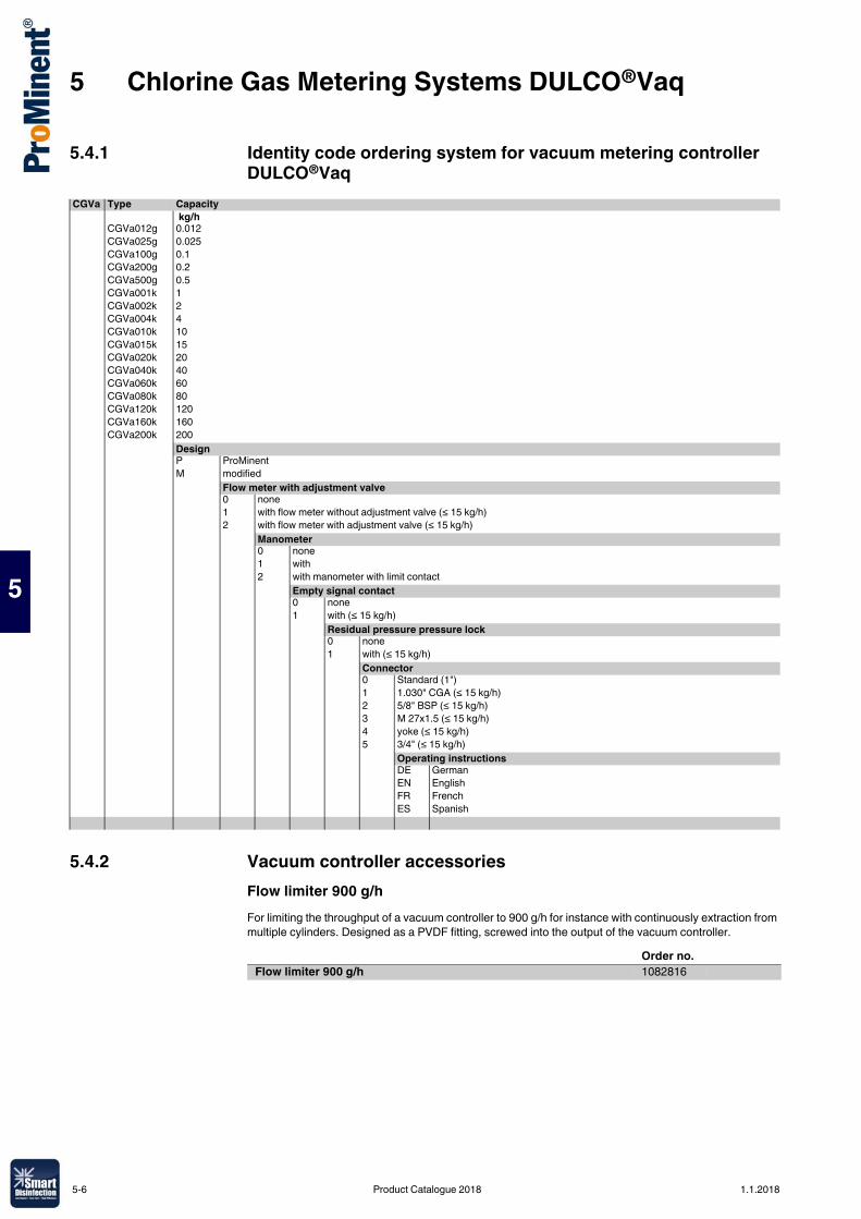
5 Chlorine Gas Metering Systems DULCO®Vaq
5
5.4.1 Identity code ordering system for vacuum metering controller DULCO®Vaq
5.4.2 Vacuum controller accessoriesFlow limiter 900 g/hFor limiting the throughput of a vacuum controller to 900 g/h for instance with continuously extraction from multiple cylinders. Designed as a PVDF fitting, screwed into the output of the vacuum controller.
CGVa Type Capacity kg/h
CGVa012g 0.012CGVa025g 0.025CGVa100g 0.1CGVa200g 0.2CGVa500g 0.5CGVa001k 1CGVa002k 2CGVa004k 4CGVa010k 10CGVa015k 15CGVa020k 20CGVa040k 40CGVa060k 60CGVa080k 80CGVa120k 120CGVa160k 160CGVa200k 200
DesignP ProMinentM modified
Flow meter with adjustment valve0 none1 with flow meter without adjustment valve (≤ 15 kg/h)2 with flow meter with adjustment valve (≤ 15 kg/h)
Manometer0 none1 with2 with manometer with limit contact
Empty signal contact0 none1 with (≤ 15 kg/h)
Residual pressure pressure lock0 none1 with (≤ 15 kg/h)
Connector0 Standard (1")1 1.030" CGA (≤ 15 kg/h)2 5/8" BSP (≤ 15 kg/h)3 M 27x1.5 (≤ 15 kg/h)4 yoke (≤ 15 kg/h)5 3/4" (≤ 15 kg/h)
Operating instructionsDE GermanEN EnglishFR FrenchES Spanish
Order no.Flow limiter 900 g/h 1082816
5-6 Product Catalogue 2018 1.1.2018
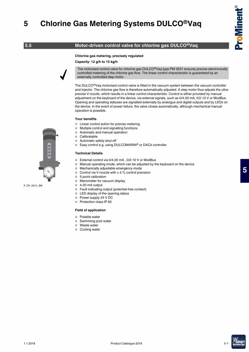
5 Chlorine Gas Metering Systems DULCO®Vaq
5
Chlorine gas metering, precisely regulatedCapacity: 12 g/h to 15 kg/h
The DULCO®Vaq motorised control valve is fitted in the vacuum system between the vacuum controller and injector. The chlorine gas flow is therefore automatically adjusted. A step motor thus adjusts the ultra-precise V-nozzle, which results in a linear control characteristic. Control is either provided by manual adjustment on the keyboard of the device, via external signals, such as 0/4-20 mA, 0/2-10 V or ModBus. Opening and operating statuses are signalled externally by analogue and digital outputs and by LEDs on the device. In the event of power failure, the valve closes automatically, although mechanical manual operation is possible.
Your benefits� Linear control action for precise metering� Multiple control and signalling functions� Automatic and manual operation� Calibratable� Automatic safety shut-off� Easy control e.g. using DULCOMARIN® or DACb controller
Technical Details� External control via 0/4-20 mA , 0/2-10 V or ModBus� Manual operating mode, which can be adjusted by the keyboard on the device� Mechanically adjustable emergency mode� Control via V-nozzle with ± 5 % control precision� 5-point calibration� Manometer for vacuum display� 4-20 mA output� Fault indicating output (potential-free contact)� LED display of the opening status� Power supply 24 V DC� Protection class IP 65
Field of application� Potable water� Swimming pool water� Waste water� Cooling water
5.5 Motor-driven control valve for chlorine gas DULCO®Vaq
The motorised control valve for chlorine gas DULCO®Vaq type PM 3531 ensures precise electronically controlled metering of the chlorine gas flow. The linear control characteristic is guaranteed by an externally controlled step motor.
P_DV_0012_SW
1.1.2018 Product Catalogue 2018 5-7
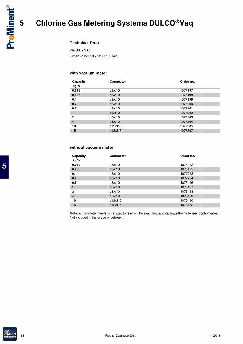
5 Chlorine Gas Metering Systems DULCO®Vaq
5
Technical DataWeight: 2.9 kgDimensions: 320 x 120 x 160 mm
with vacuum meter
without vacuum meter
Note: A flow meter needs to be fitted to read off the exact flow and calibrate the motorised control valve. Not included in the scope of delivery.
Capacity Connector Order no. kg/h0.012 d8/d10 10771970.025 d8/d10 10771980.1 d8/d10 10771990.2 d8/d10 10772000.5 d8/d10 10772011 d8/d10 10772022 d8/d10 10772034 d8/d10 107720410 d12/d16 107720515 d12/d16 1077207
Capacity Connector Order no. kg/h0.012 d8/d10 10784220.25 d8/d10 10784250.1 d8/d10 10777230.2 d8/d10 10777640.5 d8/d10 10784261 d8/d10 10784272 d8/d10 10784284 d8/d10 107842910 d12/d16 107843015 d12/d16 1078432
5-8 Product Catalogue 2018 1.1.2018
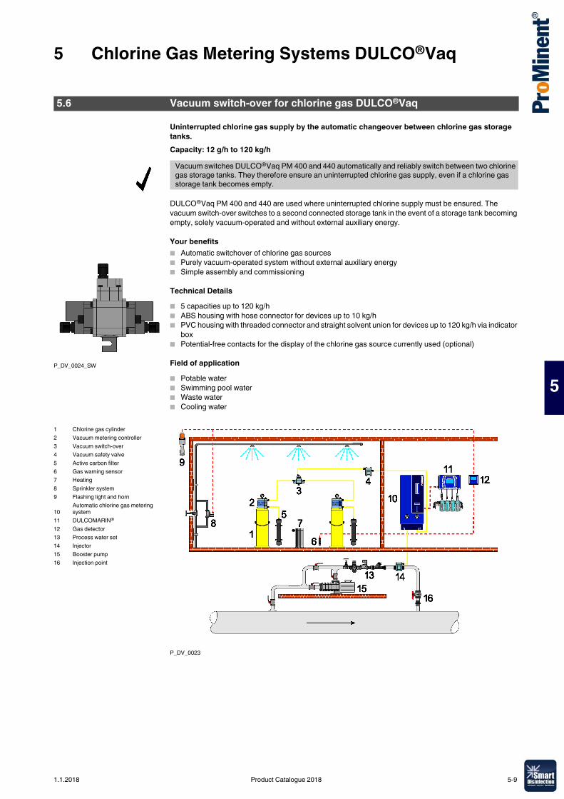
5 Chlorine Gas Metering Systems DULCO®Vaq
5
Uninterrupted chlorine gas supply by the automatic changeover between chlorine gas storage tanks. Capacity: 12 g/h to 120 kg/h
DULCO®Vaq PM 400 and 440 are used where uninterrupted chlorine supply must be ensured. The vacuum switch-over switches to a second connected storage tank in the event of a storage tank becoming empty, solely vacuum-operated and without external auxiliary energy.
Your benefits� Automatic switchover of chlorine gas sources� Purely vacuum-operated system without external auxiliary energy� Simple assembly and commissioning
Technical Details� 5 capacities up to 120 kg/h� ABS housing with hose connector for devices up to 10 kg/h� PVC housing with threaded connector and straight solvent union for devices up to 120 kg/h via indicator
box� Potential-free contacts for the display of the chlorine gas source currently used (optional)
Field of application� Potable water� Swimming pool water� Waste water� Cooling water
P_DV_0023
5.6 Vacuum switch-over for chlorine gas DULCO®Vaq
Vacuum switches DULCO®Vaq PM 400 and 440 automatically and reliably switch between two chlorine gas storage tanks. They therefore ensure an uninterrupted chlorine gas supply, even if a chlorine gas storage tank becomes empty.
P_DV_0024_SW
1 Chlorine gas cylinder2 Vacuum metering controller3 Vacuum switch-over4 Vacuum safety valve5 Active carbon filter6 Gas warning sensor7 Heating8 Sprinkler system9 Flashing light and horn
10Automatic chlorine gas metering system
11 DULCOMARIN®
12 Gas detector13 Process water set14 Injector15 Booster pump16 Injection point
1.1.2018 Product Catalogue 2018 5-9
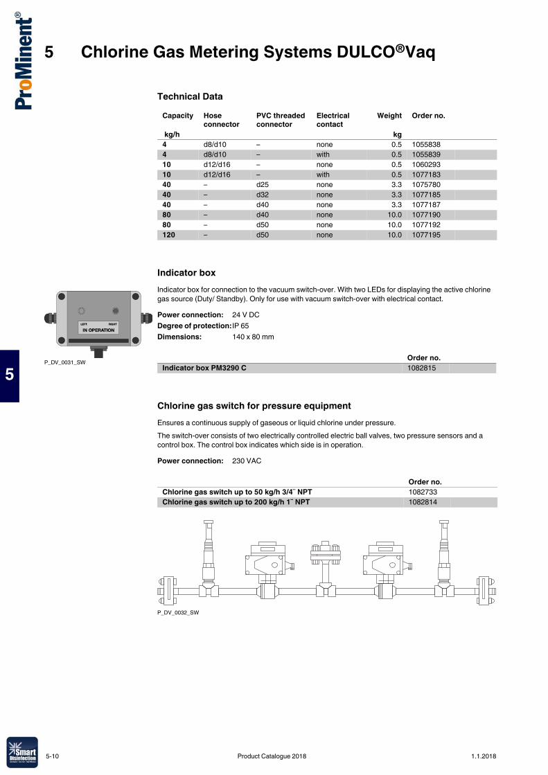
5 Chlorine Gas Metering Systems DULCO®Vaq
5
Technical Data
Indicator boxIndicator box for connection to the vacuum switch-over. With two LEDs for displaying the active chlorine gas source (Duty/ Standby). Only for use with vacuum switch-over with electrical contact.
Chlorine gas switch for pressure equipmentEnsures a continuous supply of gaseous or liquid chlorine under pressure.The switch-over consists of two electrically controlled electric ball valves, two pressure sensors and a control box. The control box indicates which side is in operation.
P_DV_0032_SW
Capacity Hose connector
PVC threaded connector
Electrical contact
Weight Order no.
kg/h kg4 d8/d10 – none 0.5 10558384 d8/d10 – with 0.5 105583910 d12/d16 – none 0.5 106029310 d12/d16 – with 0.5 107718340 – d25 none 3.3 107578040 – d32 none 3.3 107718540 – d40 none 3.3 107718780 – d40 none 10.0 107719080 – d50 none 10.0 1077192120 – d50 none 10.0 1077195
P_DV_0031_SW
Power connection: 24 V DCDegree of protection: IP 65Dimensions: 140 x 80 mm
Order no.Indicator box PM3290 C 1082815
Power connection: 230 VAC
Order no.Chlorine gas switch up to 50 kg/h 3/4¨ NPT 1082733Chlorine gas switch up to 200 kg/h 1¨ NPT 1082814
5-10 Product Catalogue 2018 1.1.2018
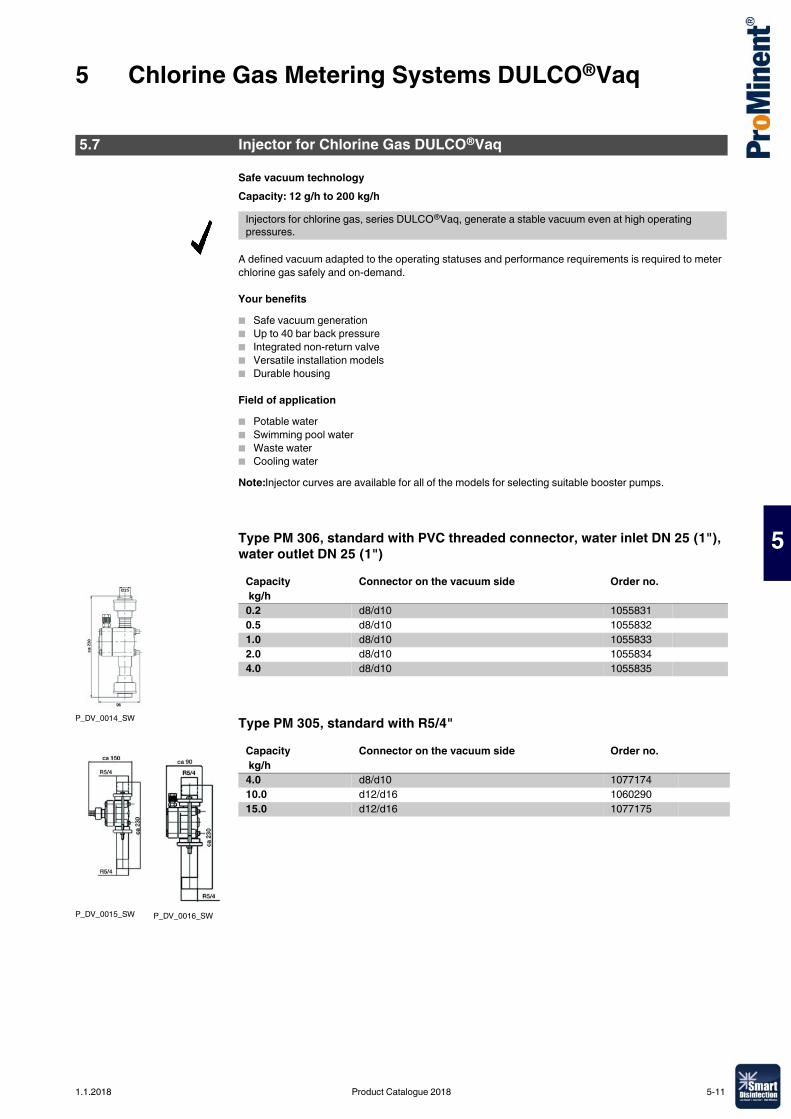
5 Chlorine Gas Metering Systems DULCO®Vaq
5
Safe vacuum technologyCapacity: 12 g/h to 200 kg/h
A defined vacuum adapted to the operating statuses and performance requirements is required to meter chlorine gas safely and on-demand.
Your benefits� Safe vacuum generation� Up to 40 bar back pressure� Integrated non-return valve� Versatile installation models� Durable housing
Field of application� Potable water� Swimming pool water� Waste water� Cooling waterNote:Injector curves are available for all of the models for selecting suitable booster pumps.
Type PM 306, standard with PVC threaded connector, water inlet DN 25 (1"), water outlet DN 25 (1")
Type PM 305, standard with R5/4"
5.7 Injector for Chlorine Gas DULCO®Vaq
Injectors for chlorine gas, series DULCO®Vaq, generate a stable vacuum even at high operating pressures.
P_DV_0014_SW
Capacity Connector on the vacuum side Order no. kg/h0.2 d8/d10 10558310.5 d8/d10 10558321.0 d8/d10 10558332.0 d8/d10 10558344.0 d8/d10 1055835
P_DV_0015_SW P_DV_0016_SW
Capacity Connector on the vacuum side Order no. kg/h4.0 d8/d10 107717410.0 d12/d16 106029015.0 d12/d16 1077175
1.1.2018 Product Catalogue 2018 5-11
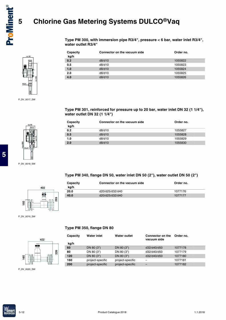
5 Chlorine Gas Metering Systems DULCO®Vaq
5
Type PM 300, with immersion pipe R3/4", pressure < 6 bar, water inlet R3/4", water outlet R3/4"
Type PM 301, reinforced for pressure up to 20 bar, water inlet DN 32 (1 1/4"), water outlet DN 32 (1 1/4")
Type PM 340, flange DN 50, water inlet DN 50 (2"), water outlet DN 50 (2")
Type PM 350, flange DN 80
P_DV_0017_SW
Capacity Connector on the vacuum side Order no. kg/h0.2 d8/d10 10558220.5 d8/d10 10558231.0 d8/d10 10558242.0 d8/d10 10558254.0 d8/d10 1055826
P_DV_0018_SW
Capacity Connector on the vacuum side Order no. kg/h0.2 d8/d10 10558270.5 d8/d10 10558281.0 d8/d10 10558292.0 d8/d10 1055830
P_DV_0019_SW
Capacity Connector on the vacuum side Order no. kg/h20.0 d20/d25/d32/d40 107717640.0 d20/d25/d32/d40 1077177
P_DV_0020_SW
Capacity Water inlet Water outlet Connector on the vacuum side
Order no.
kg/h60 DN 80 (3") DN 80 (3") d32/d40/d50 107717880 DN 80 (3") DN 80 (3") d32/d40/d50 1077179120 DN 80 (3") DN 80 (3") d32/d40/d50 1077180160 project-specific project-specific – 1077181200 project-specific project-specific – 1077182
5-12 Product Catalogue 2018 1.1.2018
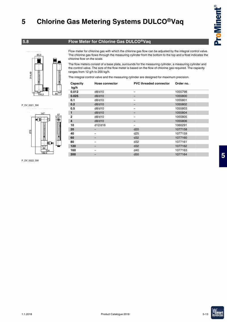
5 Chlorine Gas Metering Systems DULCO®Vaq
5
Flow meter for chlorine gas with which the chlorine gas flow can be adjusted by the integral control valve. The chlorine gas flows through the measuring cylinder from the bottom to the top and a float indicates the chlorine flow on the scale.The flow meters consist of a base plate, surrounds for the measuring cylinder, a measuring cylinder and the control valve. The size of the flow meter is based on the flow of chlorine gas required. The capacity ranges from 12 g/h to 200 kg/h.The integral control valve and the measuring cylinder are designed for maximum precision.
5.8 Flow Meter for Chlorine Gas DULCO®Vaq
P_DV_0021_SW
P_DV_0022_SW
Capacity Hose connector PVC threaded connector Order no. kg/h0.012 d8/d10 – 10557980.025 d8/d10 – 10558000.1 d8/d10 – 10558010.2 d8/d10 – 10558020.5 d8/d10 – 10558031 d8/d10 – 10558042 d8/d10 – 10558054 d8/d10 – 105580610 d12/d16 – 106029120 – d20 107715840 – d25 107715960 – d32 107716080 – d32 1077161120 – d32 1077162160 – d40 1077163200 – d50 1077164
1.1.2018 Product Catalogue 2018 5-13
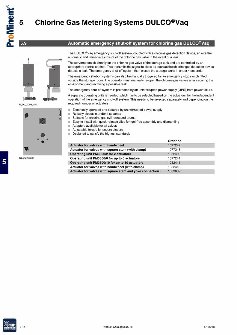
5 Chlorine Gas Metering Systems DULCO®Vaq
5
The DULCO®Vaq emergency shut-off system, coupled with a chlorine gas detection device, ensure the automatic and immediate closure of the chlorine gas valve in the event of a leak.The servomotors sit directly on the chlorine gas valve of the storage tank and are controlled by an appropriate control cabinet. This transmits the signal to close as soon as the chlorine gas detection device detects a leak. The emergency shut-off system then closes the storage tanks in under 4 seconds.The emergency shut-off systems can also be manually triggered by an emergency stop switch fitted outside the storage room. The operator must manually re-open the chlorine gas valves after securing the environment and rectifying a possible leak.The emergency shut-off system is protected by an uninterrupted power supply (UPS) from power failure.A separate operating units is needed, which has to be selected based on the actuators, for the independent operation of the emergency shut-off system. This needs to be selected separately and depending on the required number of actuators.� Electrically operated and secured by uninterrupted power supply� Reliably closes in under 4 seconds� Suitable for chlorine gas cylinders and drums� Easy to install with quick-release clips for tool-free assembly and dismantling� Adapters available for all valves� Adjustable torque for secure closure� Designed to satisfy the highest standards
5.9 Automatic emergency shut-off system for chlorine gas DULCO®Vaq
P_DV_0003_SW
Operating unit
Order no.Actuator for valves with handwheel 1077242Actuator for valves with square stem (with clamp) 1077243Operating unit PM3800/2 for 2 actuators 1082409Operating unit PM3800/6 for up to 6 actuators 1077244Operating unit PM3800/10 for up to 10 actuators 1082411Actuator for valves with handwheel (with clamp) 1082413Actuator for valves with square stem and yoke connection 1083832
5-14 Product Catalogue 2018 1.1.2018
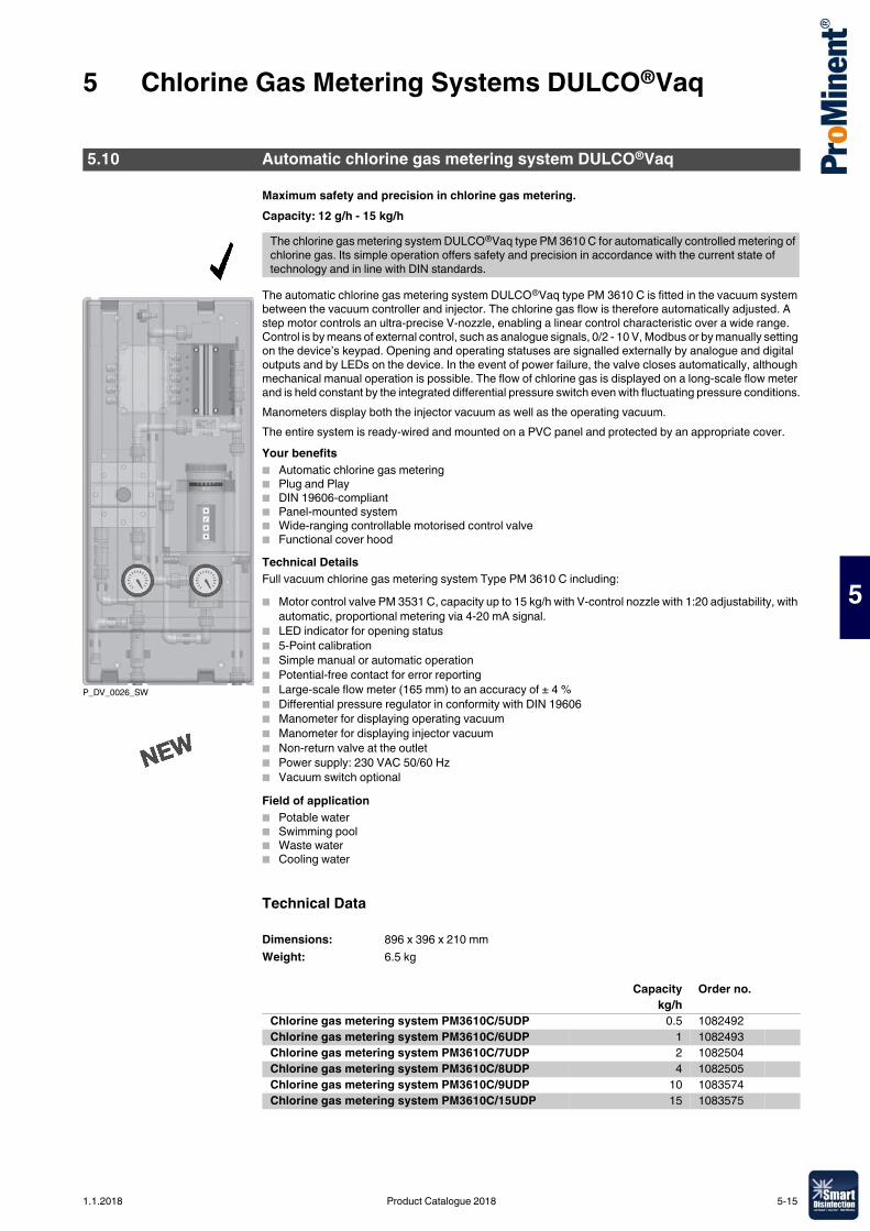
5 Chlorine Gas Metering Systems DULCO®Vaq
5
Maximum safety and precision in chlorine gas metering.Capacity: 12 g/h - 15 kg/h
The automatic chlorine gas metering system DULCO®Vaq type PM 3610 C is fitted in the vacuum system between the vacuum controller and injector. The chlorine gas flow is therefore automatically adjusted. A step motor controls an ultra-precise V-nozzle, enabling a linear control characteristic over a wide range. Control is by means of external control, such as analogue signals, 0/2 - 10 V, Modbus or by manually setting on the device’s keypad. Opening and operating statuses are signalled externally by analogue and digital outputs and by LEDs on the device. In the event of power failure, the valve closes automatically, although mechanical manual operation is possible. The flow of chlorine gas is displayed on a long-scale flow meter and is held constant by the integrated differential pressure switch even with fluctuating pressure conditions.Manometers display both the injector vacuum as well as the operating vacuum.The entire system is ready-wired and mounted on a PVC panel and protected by an appropriate cover.Your benefits� Automatic chlorine gas metering� Plug and Play� DIN 19606-compliant� Panel-mounted system� Wide-ranging controllable motorised control valve� Functional cover hoodTechnical DetailsFull vacuum chlorine gas metering system Type PM 3610 C including:� Motor control valve PM 3531 C, capacity up to 15 kg/h with V-control nozzle with 1:20 adjustability, with
automatic, proportional metering via 4-20 mA signal.� LED indicator for opening status� 5-Point calibration� Simple manual or automatic operation� Potential-free contact for error reporting� Large-scale flow meter (165 mm) to an accuracy of ± 4 %� Differential pressure regulator in conformity with DIN 19606� Manometer for displaying operating vacuum� Manometer for displaying injector vacuum� Non-return valve at the outlet� Power supply: 230 VAC 50/60 Hz� Vacuum switch optionalField of application� Potable water� Swimming pool� Waste water� Cooling water
Technical Data
5.10 Automatic chlorine gas metering system DULCO®Vaq
The chlorine gas metering system DULCO®Vaq type PM 3610 C for automatically controlled metering of chlorine gas. Its simple operation offers safety and precision in accordance with the current state of technology and in line with DIN standards.
P_DV_0026_SW
Dimensions: 896 x 396 x 210 mmWeight: 6.5 kg
Capacity Order no. kg/h
Chlorine gas metering system PM3610C/5UDP 0.5 1082492Chlorine gas metering system PM3610C/6UDP 1 1082493Chlorine gas metering system PM3610C/7UDP 2 1082504Chlorine gas metering system PM3610C/8UDP 4 1082505Chlorine gas metering system PM3610C/9UDP 10 1083574Chlorine gas metering system PM3610C/15UDP 15 1083575
1.1.2018 Product Catalogue 2018 5-15
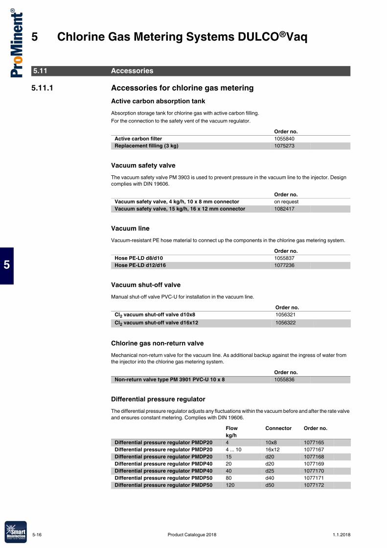
5 Chlorine Gas Metering Systems DULCO®Vaq
5
5.11.1 Accessories for chlorine gas meteringActive carbon absorption tankAbsorption storage tank for chlorine gas with active carbon filling.For the connection to the safety vent of the vacuum regulator.
Vacuum safety valveThe vacuum safety valve PM 3903 is used to prevent pressure in the vacuum line to the injector. Design complies with DIN 19606.
Vacuum lineVacuum-resistant PE hose material to connect up the components in the chlorine gas metering system.
Vacuum shut-off valveManual shut-off valve PVC-U for installation in the vacuum line.
Chlorine gas non-return valveMechanical non-return valve for the vacuum line. As additional backup against the ingress of water from the injector into the chlorine gas metering system.
Differential pressure regulatorThe differential pressure regulator adjusts any fluctuations within the vacuum before and after the rate valve and ensures constant metering. Complies with DIN 19606.
5.11 Accessories
Order no.Active carbon filter 1055840Replacement filling (3 kg) 1075273
Order no.Vacuum safety valve, 4 kg/h, 10 x 8 mm connector on requestVacuum safety valve, 15 kg/h, 16 x 12 mm connector 1082417
Order no.Hose PE-LD d8/d10 1055837Hose PE-LD d12/d16 1077236
Order no.Cl2 vacuum shut-off valve d10x8 1056321Cl2 vacuum shut-off valve d16x12 1056322
Order no.Non-return valve type PM 3901 PVC-U 10 x 8 1055836
Flow Connector Order no.kg/h
Differential pressure regulator PMDP20 4 10x8 1077165Differential pressure regulator PMDP20 4 ... 10 16x12 1077167Differential pressure regulator PMDP20 15 d20 1077168Differential pressure regulator PMDP40 20 d20 1077169Differential pressure regulator PMDP40 40 d25 1077170Differential pressure regulator PMDP50 80 d40 1077171Differential pressure regulator PMDP50 120 d50 1077172
5-16 Product Catalogue 2018 1.1.2018
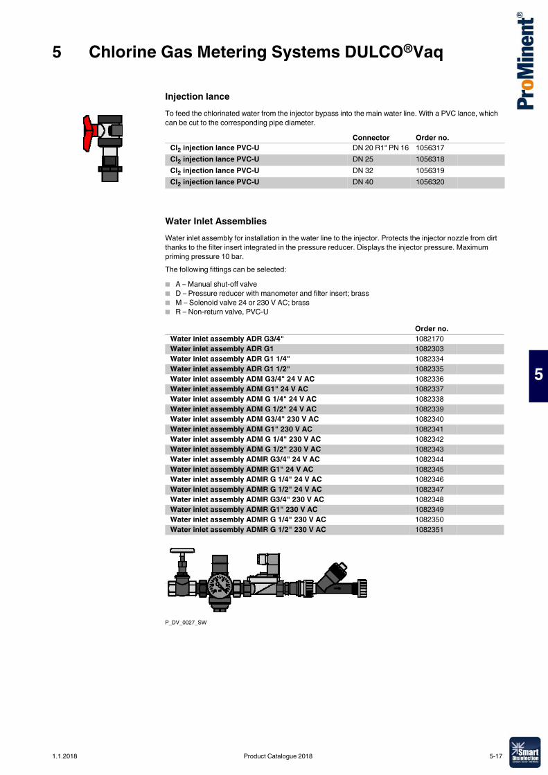
5 Chlorine Gas Metering Systems DULCO®Vaq
5
Injection lanceTo feed the chlorinated water from the injector bypass into the main water line. With a PVC lance, which can be cut to the corresponding pipe diameter.
Water Inlet AssembliesWater inlet assembly for installation in the water line to the injector. Protects the injector nozzle from dirt thanks to the filter insert integrated in the pressure reducer. Displays the injector pressure. Maximum priming pressure 10 bar.The following fittings can be selected:� A – Manual shut-off valve� D – Pressure reducer with manometer and filter insert; brass� M – Solenoid valve 24 or 230 V AC; brass� R – Non-return valve, PVC-U
P_DV_0027_SW
Connector Order no.Cl2 injection lance PVC-U DN 20 R1" PN 16 1056317Cl2 injection lance PVC-U DN 25 1056318Cl2 injection lance PVC-U DN 32 1056319Cl2 injection lance PVC-U DN 40 1056320
Order no.Water inlet assembly ADR G3/4" 1082170Water inlet assembly ADR G1 1082303Water inlet assembly ADR G1 1/4" 1082334Water inlet assembly ADR G1 1/2" 1082335Water inlet assembly ADM G3/4" 24 V AC 1082336Water inlet assembly ADM G1" 24 V AC 1082337Water inlet assembly ADM G 1/4" 24 V AC 1082338Water inlet assembly ADM G 1/2" 24 V AC 1082339Water inlet assembly ADM G3/4" 230 V AC 1082340Water inlet assembly ADM G1" 230 V AC 1082341Water inlet assembly ADM G 1/4" 230 V AC 1082342Water inlet assembly ADM G 1/2" 230 V AC 1082343Water inlet assembly ADMR G3/4" 24 V AC 1082344Water inlet assembly ADMR G1" 24 V AC 1082345Water inlet assembly ADMR G 1/4" 24 V AC 1082346Water inlet assembly ADMR G 1/2" 24 V AC 1082347Water inlet assembly ADMR G3/4" 230 V AC 1082348Water inlet assembly ADMR G1" 230 V AC 1082349Water inlet assembly ADMR G 1/4" 230 V AC 1082350Water inlet assembly ADMR G 1/2" 230 V AC 1082351
1.1.2018 Product Catalogue 2018 5-17
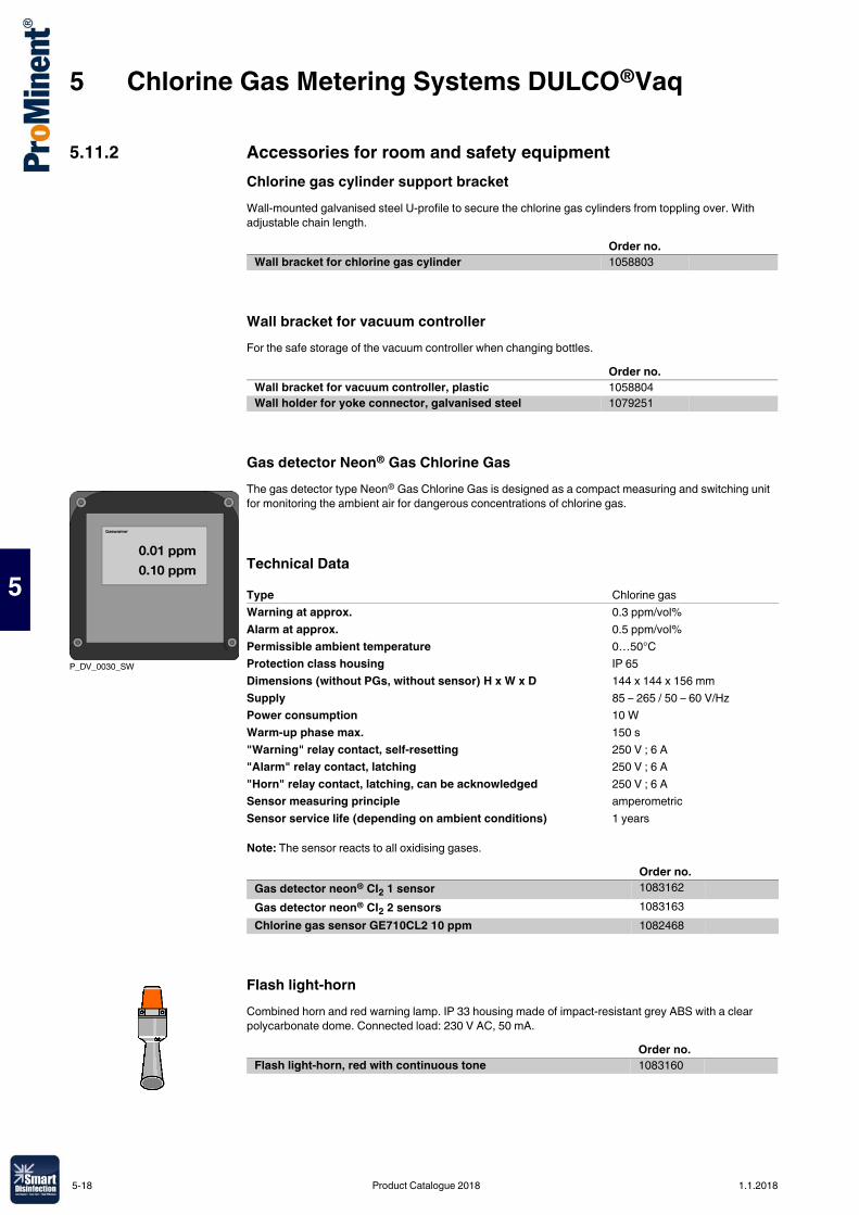
5 Chlorine Gas Metering Systems DULCO®Vaq
5
5.11.2 Accessories for room and safety equipmentChlorine gas cylinder support bracketWall-mounted galvanised steel U-profile to secure the chlorine gas cylinders from toppling over. With adjustable chain length.
Wall bracket for vacuum controllerFor the safe storage of the vacuum controller when changing bottles.
Gas detector Neon® Gas Chlorine GasThe gas detector type Neon® Gas Chlorine Gas is designed as a compact measuring and switching unit for monitoring the ambient air for dangerous concentrations of chlorine gas.
Technical Data
Note: The sensor reacts to all oxidising gases.
Flash light-hornCombined horn and red warning lamp. IP 33 housing made of impact-resistant grey ABS with a clear polycarbonate dome. Connected load: 230 V AC, 50 mA.
Order no.Wall bracket for chlorine gas cylinder 1058803
Order no.Wall bracket for vacuum controller, plastic 1058804Wall holder for yoke connector, galvanised steel 1079251
P_DV_0030_SW
Type Chlorine gasWarning at approx. 0.3 ppm/vol%Alarm at approx. 0.5 ppm/vol%Permissible ambient temperature 0…50°CProtection class housing IP 65Dimensions (without PGs, without sensor) H x W x D 144 x 144 x 156 mmSupply 85 – 265 / 50 – 60 V/HzPower consumption 10 WWarm-up phase max. 150 s"Warning" relay contact, self-resetting 250 V ; 6 A"Alarm" relay contact, latching 250 V ; 6 A"Horn" relay contact, latching, can be acknowledged 250 V ; 6 ASensor measuring principle amperometricSensor service life (depending on ambient conditions) 1 years
Order no.Gas detector neon® CI2 1 sensor 1083162Gas detector neon® CI2 2 sensors 1083163Chlorine gas sensor GE710CL2 10 ppm 1082468
Order no.Flash light-horn, red with continuous tone 1083160
5-18 Product Catalogue 2018 1.1.2018
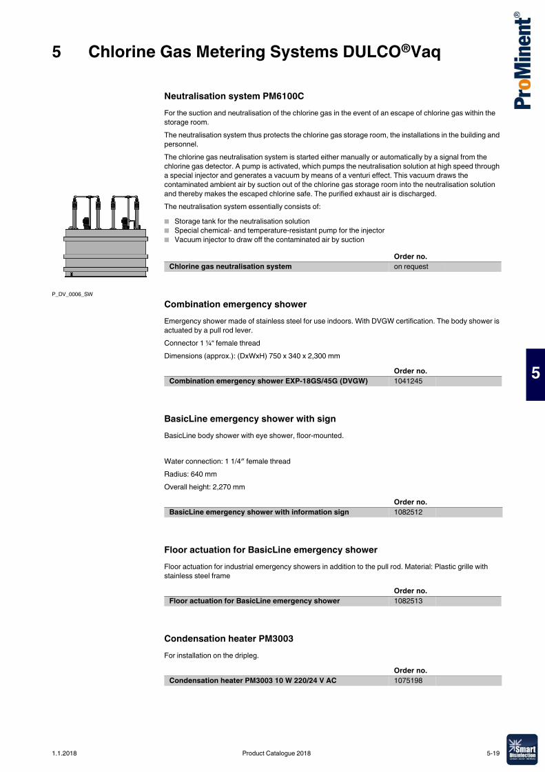
5 Chlorine Gas Metering Systems DULCO®Vaq
5
Neutralisation system PM6100CFor the suction and neutralisation of the chlorine gas in the event of an escape of chlorine gas within the storage room.The neutralisation system thus protects the chlorine gas storage room, the installations in the building and personnel.The chlorine gas neutralisation system is started either manually or automatically by a signal from the chlorine gas detector. A pump is activated, which pumps the neutralisation solution at high speed through a special injector and generates a vacuum by means of a venturi effect. This vacuum draws the contaminated ambient air by suction out of the chlorine gas storage room into the neutralisation solution and thereby makes the escaped chlorine safe. The purified exhaust air is discharged.The neutralisation system essentially consists of:� Storage tank for the neutralisation solution� Special chemical- and temperature-resistant pump for the injector� Vacuum injector to draw off the contaminated air by suction
Combination emergency showerEmergency shower made of stainless steel for use indoors. With DVGW certification. The body shower is actuated by a pull rod lever.Connector 1 ¼“ female threadDimensions (approx.): (DxWxH) 750 x 340 x 2,300 mm
BasicLine emergency shower with signBasicLine body shower with eye shower, floor-mounted.
Water connection: 1 1/4″ female threadRadius: 640 mmOverall height: 2,270 mm
Floor actuation for BasicLine emergency showerFloor actuation for industrial emergency showers in addition to the pull rod. Material: Plastic grille with stainless steel frame
Condensation heater PM3003For installation on the dripleg.
P_DV_0006_SW
Order no.Chlorine gas neutralisation system on request
Order no.Combination emergency shower EXP-18GS/45G (DVGW) 1041245
Order no.BasicLine emergency shower with information sign 1082512
Order no.Floor actuation for BasicLine emergency shower 1082513
Order no.Condensation heater PM3003 10 W 220/24 V AC 1075198
1.1.2018 Product Catalogue 2018 5-19
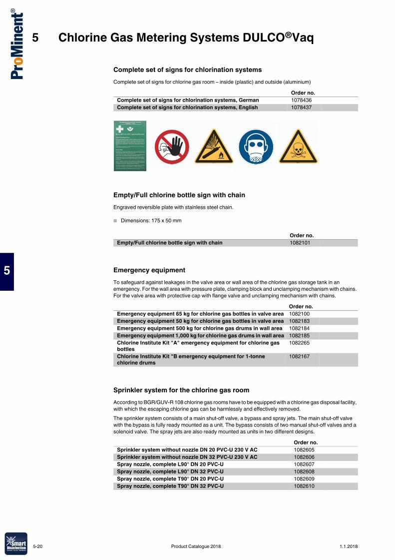
5 Chlorine Gas Metering Systems DULCO®Vaq
5
Complete set of signs for chlorination systemsComplete set of signs for chlorine gas room – inside (plastic) and outside (aluminium)
Empty/Full chlorine bottle sign with chainEngraved reversible plate with stainless steel chain.
� Dimensions: 175 x 50 mm
Emergency equipmentTo safeguard against leakages in the valve area or wall area of the chlorine gas storage tank in an emergency. For the wall area with pressure plate, clamping block and unclamping mechanism with chains. For the valve area with protective cap with flange valve and unclamping mechanism with chains.
Sprinkler system for the chlorine gas roomAccording to BGR/GUV-R 108 chlorine gas rooms have to be equipped with a chlorine gas disposal facility, with which the escaping chlorine gas can be harmlessly and effectively removed.The sprinkler system consists of a main shut-off valve, a bypass and spray jets. The main shut-off valve with the bypass is fully ready mounted as a unit. The bypass consists of two manual shut-off valves and a solenoid valve. The spray jets are also ready mounted as units in two different designs.
Order no.Complete set of signs for chlorination systems, German 1078436Complete set of signs for chlorination systems, English 1078437
Order no.Empty/Full chlorine bottle sign with chain 1082101
Order no.Emergency equipment 65 kg for chlorine gas bottles in valve area 1082100Emergency equipment 50 kg for chlorine gas bottles in valve area 1082183Emergency equipment 500 kg for chlorine gas drums in wall area 1082184Emergency equipment 1,000 kg for chlorine gas drums in wall area 1082185Chlorine Institute Kit "A" emergency equipment for chlorine gas bottles
1082265
Chlorine Institute Kit "B emergency equipment for 1-tonne chlorine drums
1082167
Order no.Sprinkler system without nozzle DN 20 PVC-U 230 V AC 1082605Sprinkler system without nozzle DN 32 PVC-U 230 V AC 1082606Spray nozzle, complete L90° DN 20 PVC-U 1082607Spray nozzle, complete L90° DN 32 PVC-U 1082608Spray nozzle, complete T90° DN 20 PVC-U 1082609Spray nozzle, complete T90° DN 32 PVC-U 1082610
5-20 Product Catalogue 2018 1.1.2018
5 Chlorine Gas Metering Systems DULCO®Vaq
5
5.11.3 Other accessories
Wall fansWall-mounted axial ventilators for ventilation of chlorine gas chamber. DN 500 with quadratic mounting plate and automatic cover flap.
Chlorine gas storage tankHigh-grade safety-tested chlorine gas storage tank for use as original equipment or spare part. Supplied empty without chlorine gas.
Weighing systems and drum storageTo monitor and check the liquid level of chlorine gas bottles and drums. Barrel storage for the safe storage and alignment of the chlorine gas drums.
Crane beam and crane scalesFor the safe transport and loading of chlorine gas drums up to max. 2 tonnes.
Output Order no. m3/h
Wall fan 400 V 50 Hz 5,800 1082412Wall fan 400 V 50 Hz 2,500 1082410Wall fan 400 V 50 Hz 1,150 1082408
Volume Order no. l
Steel cylinder empty 52 l with valve W 1x8/1" 52 1082133Chlorine gas storage tank 45 bar P355NL1 EN14208 400 1082164Chlorine gas storage tank 45 bar P355NL1 EN14208 840 1082165
Order no.Electrical bottle scales GR100K-1 1 x 150 kg 1082138Electrical bottle scales GR100K-2 2 x 150 kg 1082139Hydraulic bottle scales 4D100K-1 1 x 150 kg 1082140Hydraulic bottle scales 4D100K-2 2 x 150 kg 1082141Drum scales DR20K 2,000 kg with electronic display 1082136Drum scales DR40K 4,000 kg with electronic display 1082415Drum scales 8D20K 2,000 kg with hydraulic display 1082564Drum scales 8D40K 4,000 kg with hydraulic display 1082565Drum storage on wheels, steel with PE wheels, max. 2,000 kg 1082135Drum pallet , galvanised steel 1082166
Order no.Crane beam for drum length 2,022–2,076 mm steel 1082137Chain hoist HZE020 2,000 kg 3,0 m 1082294Digital crane scales 3,000 kg IP67 230 V SS 1082295Electrical chain hoist 2,000 kg 400 V 50 Hz IP55 1082296Chain container BD4 for 4 m chain length 1082297Cable trolley for power supply, width 132 mm 1082298
1.1.2018 Product Catalogue 2018 5-21
5 Chlorine Gas Metering Systems DULCO®Vaq
5
Reaction tower with granulated marbleDuring the chlorination of water, hydrochloric acid, which lowers the pH value of the water, is also produced alongside the hypochlorous acid, which has an excellent disinfection effect. If there is insufficient carbonate hardness in the water, the buffer capacity is inadequate and can be replaced in the form of reaction filters with granulated marble.Filter storage tank made of glass fibre-reinforced epoxy resin with a seamless ABS inner liner.� Operating pressure: max. 10 bar� Operating temperature: max. 50 °C� Volume: 170 or 310 litres� Diameter of the tank: 552 mm
5.11.4 Personal safety equipmentFull face mask Dräger X-Plore 6300Efficient and cost-effective full protection respiratory mask without filter made from EPDM and a viewing panel made from scratchproof PMMA for a 180° wide-angle view.
Dräger X-plore breathing filterFor full mask XP 6300. Specifically suitable for use in chlorine gas systems.
Safety bootsWater-tight and slip-resistant.
Acid apron
Compressed air breathing apparatus, Diablo Rina 1800 Marine� Back carrier panel with belt strap carrier� Overpressure breathing regulator� Pressure reducer with safety valve� Manometer� Acoustic warning device� including full mask C607/SPA (Class 3) with screw connector M45x3 (DIN EN 148-3)� including compressed air cylinder (6 l, 300 bar) steel� Operating period approx. 45 minutes (1800 l breathing air)
Order no.Reaction tower HClO 170 l 10 bar epoxy/PE 1082168Reaction tower HClO 310 l 10 bar epoxy/PE 1082169Filter material CaCO3 4.0 – 6.0 mm unit kg 1082544
Order no.Dräger full mask XP 6300 EN136 class 2 1082117
Order no.Dräger X-plore breathing filter Rd40 940A2B2 EN143 1082118
Order no.Safety boots, yellow Size 45 PVC S5 SRA 1082122
Order no.Acid apron 100 x 120 cm PVC with fabric; black 1082123
Order no.Compressed air breathing apparatus, Diablo Rina 1800 Marine 1082124
5-22 Product Catalogue 2018 1.1.2018
5 Chlorine Gas Metering Systems DULCO®Vaq
5
Compressed air cylinderAs replacement cylinder for compressed air breathing apparatus Diablo Rina 1800 (order no. 1082124).
Protective gloves
Chemical suit VS5 Polyran-LOne-part complete full-body chemical protective suit with fixed visor; gas-tight chemical protective suite with breathing air supply carried in the suit independent of the ambient air, i.e. a storage device with compressed air. Inclusive of gloves and safety boots.Re-usable, washable, very good mechanical properties (tear-resistant, wear-resistant, puncture-resistant).Certification: DIN EN 943 Part 1 –1a (Industry)
Order no.Compressed air cylinder 6 litres – 300 bar steel 1082173
Order no.Protective gloves 640 PVC, Size10 Cat.3 1082126
Order no.Chemical suit VS5 Polyran-L, yellow 1082509
1.1.2018 Product Catalogue 2018 5-23
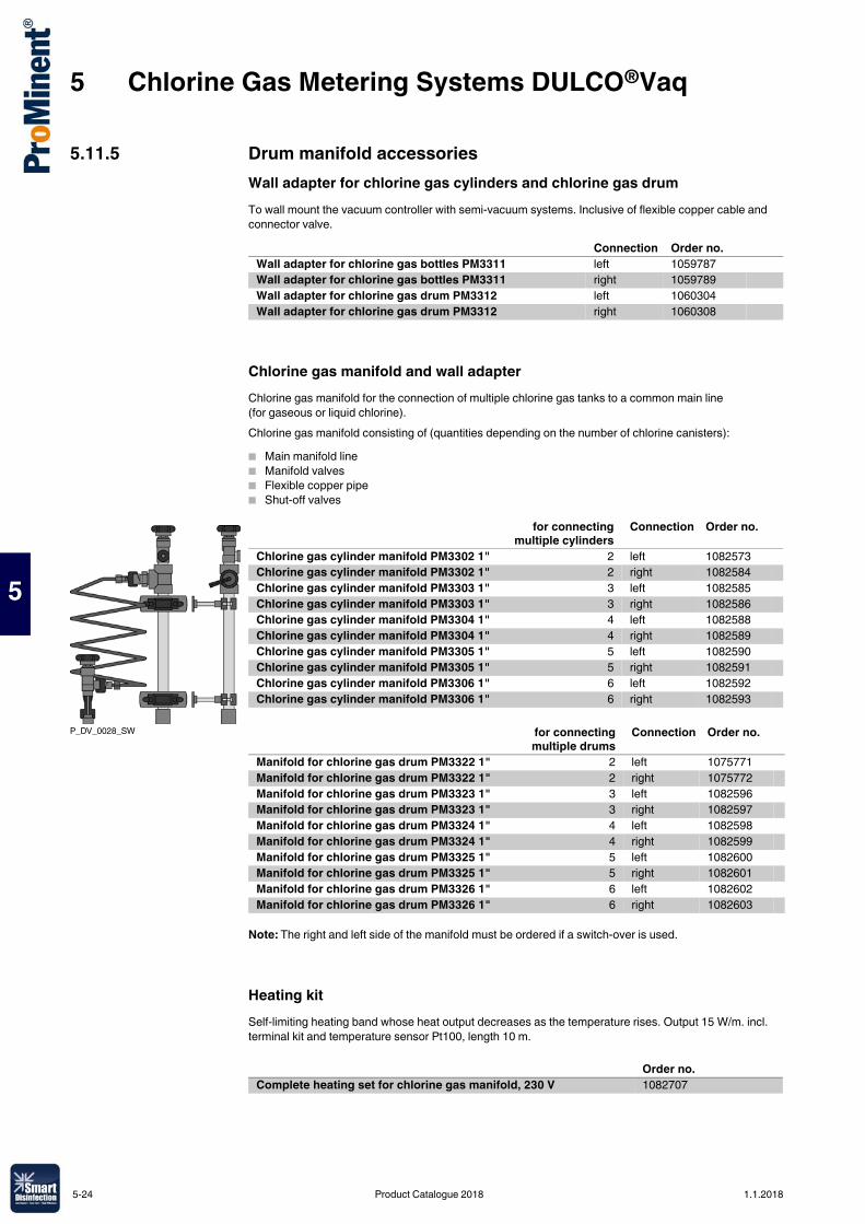
5 Chlorine Gas Metering Systems DULCO®Vaq
5
5.11.5 Drum manifold accessoriesWall adapter for chlorine gas cylinders and chlorine gas drumTo wall mount the vacuum controller with semi-vacuum systems. Inclusive of flexible copper cable and connector valve.
Chlorine gas manifold and wall adapterChlorine gas manifold for the connection of multiple chlorine gas tanks to a common main line (for gaseous or liquid chlorine).Chlorine gas manifold consisting of (quantities depending on the number of chlorine canisters):� Main manifold line� Manifold valves� Flexible copper pipe� Shut-off valves
Note: The right and left side of the manifold must be ordered if a switch-over is used.
Heating kitSelf-limiting heating band whose heat output decreases as the temperature rises. Output 15 W/m. incl. terminal kit and temperature sensor Pt100, length 10 m.
Connection Order no.Wall adapter for chlorine gas bottles PM3311 left 1059787Wall adapter for chlorine gas bottles PM3311 right 1059789Wall adapter for chlorine gas drum PM3312 left 1060304Wall adapter for chlorine gas drum PM3312 right 1060308
P_DV_0028_SW
for connectingmultiple cylinders
Connection Order no.
Chlorine gas cylinder manifold PM3302 1" 2 left 1082573Chlorine gas cylinder manifold PM3302 1" 2 right 1082584Chlorine gas cylinder manifold PM3303 1" 3 left 1082585Chlorine gas cylinder manifold PM3303 1" 3 right 1082586Chlorine gas cylinder manifold PM3304 1" 4 left 1082588Chlorine gas cylinder manifold PM3304 1" 4 right 1082589Chlorine gas cylinder manifold PM3305 1" 5 left 1082590Chlorine gas cylinder manifold PM3305 1" 5 right 1082591Chlorine gas cylinder manifold PM3306 1" 6 left 1082592Chlorine gas cylinder manifold PM3306 1" 6 right 1082593
for connectingmultiple drums
Connection Order no.
Manifold for chlorine gas drum PM3322 1" 2 left 1075771Manifold for chlorine gas drum PM3322 1" 2 right 1075772Manifold for chlorine gas drum PM3323 1" 3 left 1082596Manifold for chlorine gas drum PM3323 1" 3 right 1082597Manifold for chlorine gas drum PM3324 1" 4 left 1082598Manifold for chlorine gas drum PM3324 1" 4 right 1082599Manifold for chlorine gas drum PM3325 1" 5 left 1082600Manifold for chlorine gas drum PM3325 1" 5 right 1082601Manifold for chlorine gas drum PM3326 1" 6 left 1082602Manifold for chlorine gas drum PM3326 1" 6 right 1082603
Order no.Complete heating set for chlorine gas manifold, 230 V 1082707
5-24 Product Catalogue 2018 1.1.2018
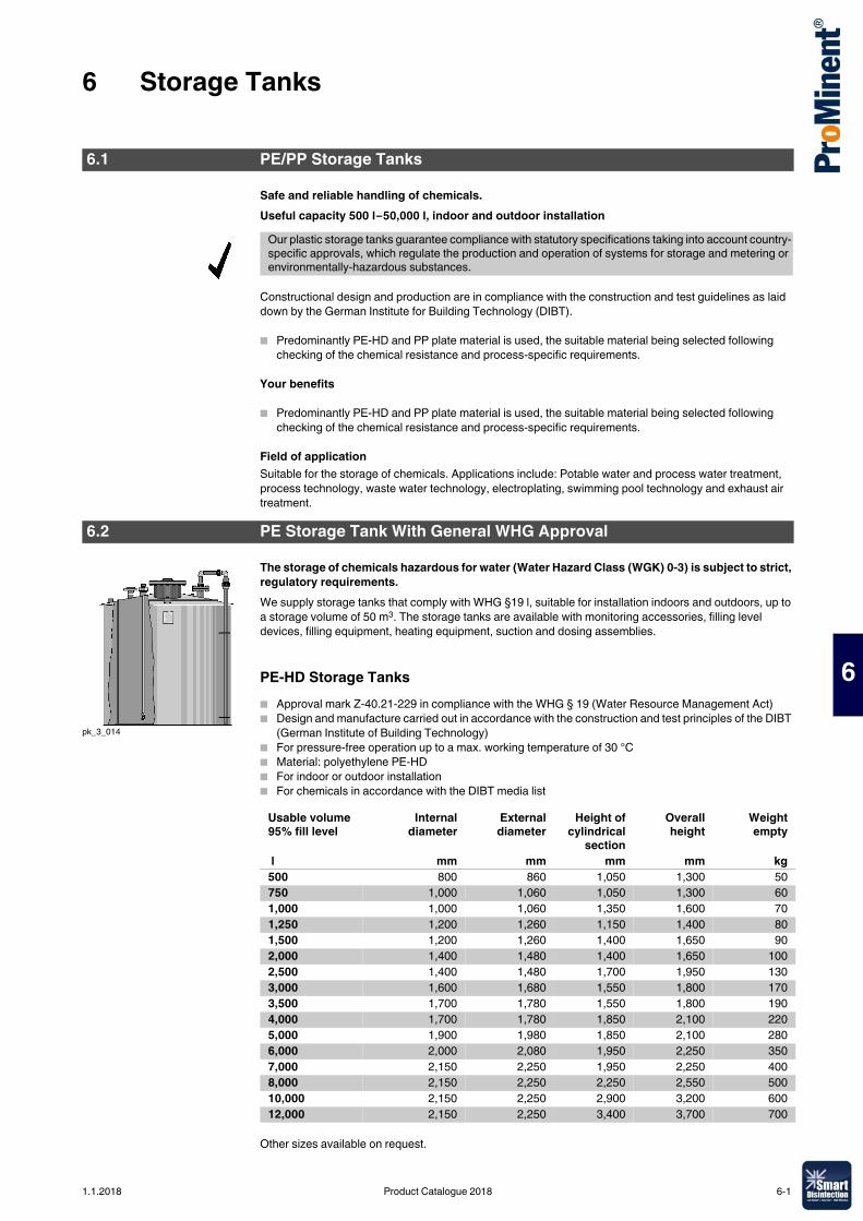
6 Storage Tanks
6
6.0.1Product Catalogue 2018
Safe and reliable handling of chemicals.Useful capacity 500 l–50,000 l, indoor and outdoor installation
Constructional design and production are in compliance with the construction and test guidelines as laid down by the German Institute for Building Technology (DIBT).
� Predominantly PE-HD and PP plate material is used, the suitable material being selected following checking of the chemical resistance and process-specific requirements.
Your benefits
� Predominantly PE-HD and PP plate material is used, the suitable material being selected following checking of the chemical resistance and process-specific requirements.
Field of applicationSuitable for the storage of chemicals. Applications include: Potable water and process water treatment, process technology, waste water technology, electroplating, swimming pool technology and exhaust air treatment.
The storage of chemicals hazardous for water (Water Hazard Class (WGK) 0-3) is subject to strict, regulatory requirements.We supply storage tanks that comply with WHG §19 l, suitable for installation indoors and outdoors, up to a storage volume of 50 m3. The storage tanks are available with monitoring accessories, filling level devices, filling equipment, heating equipment, suction and dosing assemblies.
PE-HD Storage Tanks� Approval mark Z-40.21-229 in compliance with the WHG § 19 (Water Resource Management Act)� Design and manufacture carried out in accordance with the construction and test principles of the DIBT
(German Institute of Building Technology)� For pressure-free operation up to a max. working temperature of 30 °C� Material: polyethylene PE-HD� For indoor or outdoor installation� For chemicals in accordance with the DIBT media list
Other sizes available on request.
6.1 PE/PP Storage Tanks
Our plastic storage tanks guarantee compliance with statutory specifications taking into account country-specific approvals, which regulate the production and operation of systems for storage and metering or environmentally-hazardous substances.
6.2 PE Storage Tank With General WHG Approval
pk_3_014
Usable volume 95% fill level
Internaldiameter
Externaldiameter
Height ofcylindrical
section
Overallheight
Weightempty
l mm mm mm mm kg500 800 860 1,050 1,300 50750 1,000 1,060 1,050 1,300 601,000 1,000 1,060 1,350 1,600 701,250 1,200 1,260 1,150 1,400 801,500 1,200 1,260 1,400 1,650 902,000 1,400 1,480 1,400 1,650 1002,500 1,400 1,480 1,700 1,950 1303,000 1,600 1,680 1,550 1,800 1703,500 1,700 1,780 1,550 1,800 1904,000 1,700 1,780 1,850 2,100 2205,000 1,900 1,980 1,850 2,100 2806,000 2,000 2,080 1,950 2,250 3507,000 2,150 2,250 1,950 2,250 4008,000 2,150 2,250 2,250 2,550 50010,000 2,150 2,250 2,900 3,200 60012,000 2,150 2,250 3,400 3,700 700
1.1.2018 Product Catalogue 2018 6-1
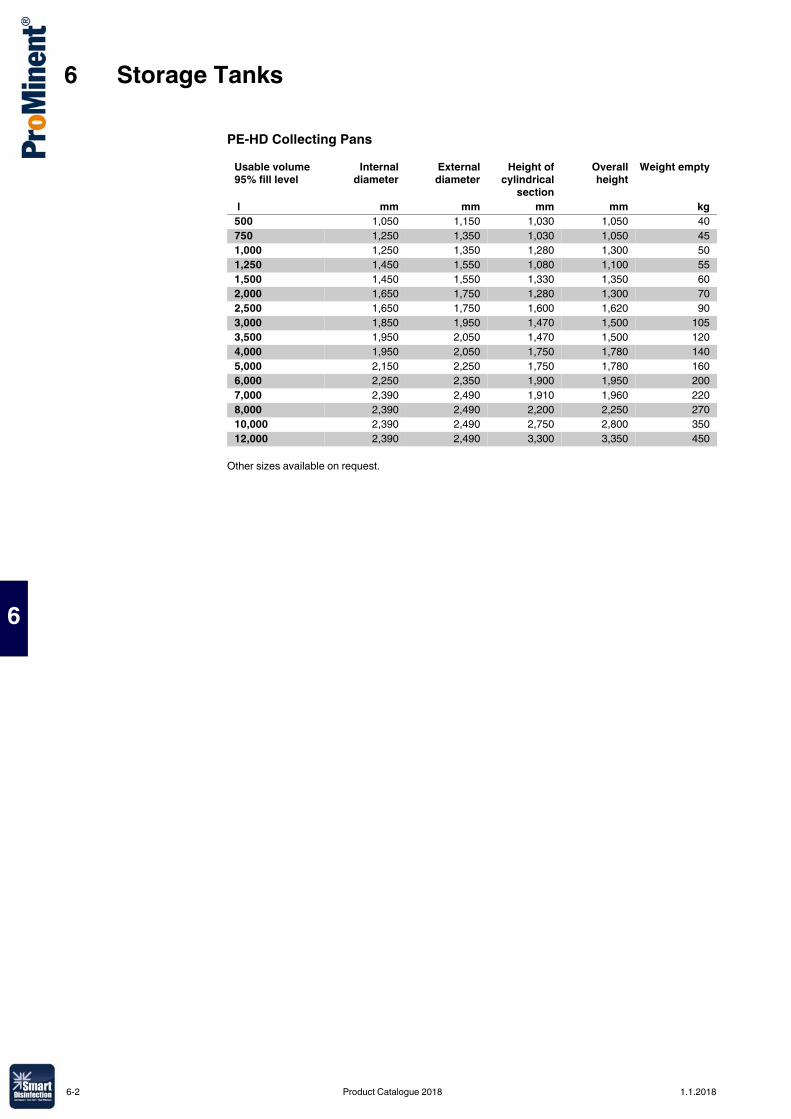
6 Storage Tanks
6
PE-HD Collecting Pans
Other sizes available on request.
Usable volume 95% fill level
Internaldiameter
Externaldiameter
Height ofcylindrical
section
Overallheight
Weight empty
l mm mm mm mm kg500 1,050 1,150 1,030 1,050 40750 1,250 1,350 1,030 1,050 451,000 1,250 1,350 1,280 1,300 501,250 1,450 1,550 1,080 1,100 551,500 1,450 1,550 1,330 1,350 602,000 1,650 1,750 1,280 1,300 702,500 1,650 1,750 1,600 1,620 903,000 1,850 1,950 1,470 1,500 1053,500 1,950 2,050 1,470 1,500 1204,000 1,950 2,050 1,750 1,780 1405,000 2,150 2,250 1,750 1,780 1606,000 2,250 2,350 1,900 1,950 2007,000 2,390 2,490 1,910 1,960 2208,000 2,390 2,490 2,200 2,250 27010,000 2,390 2,490 2,750 2,800 35012,000 2,390 2,490 3,300 3,350 450
6-2 Product Catalogue 2018 1.1.2018
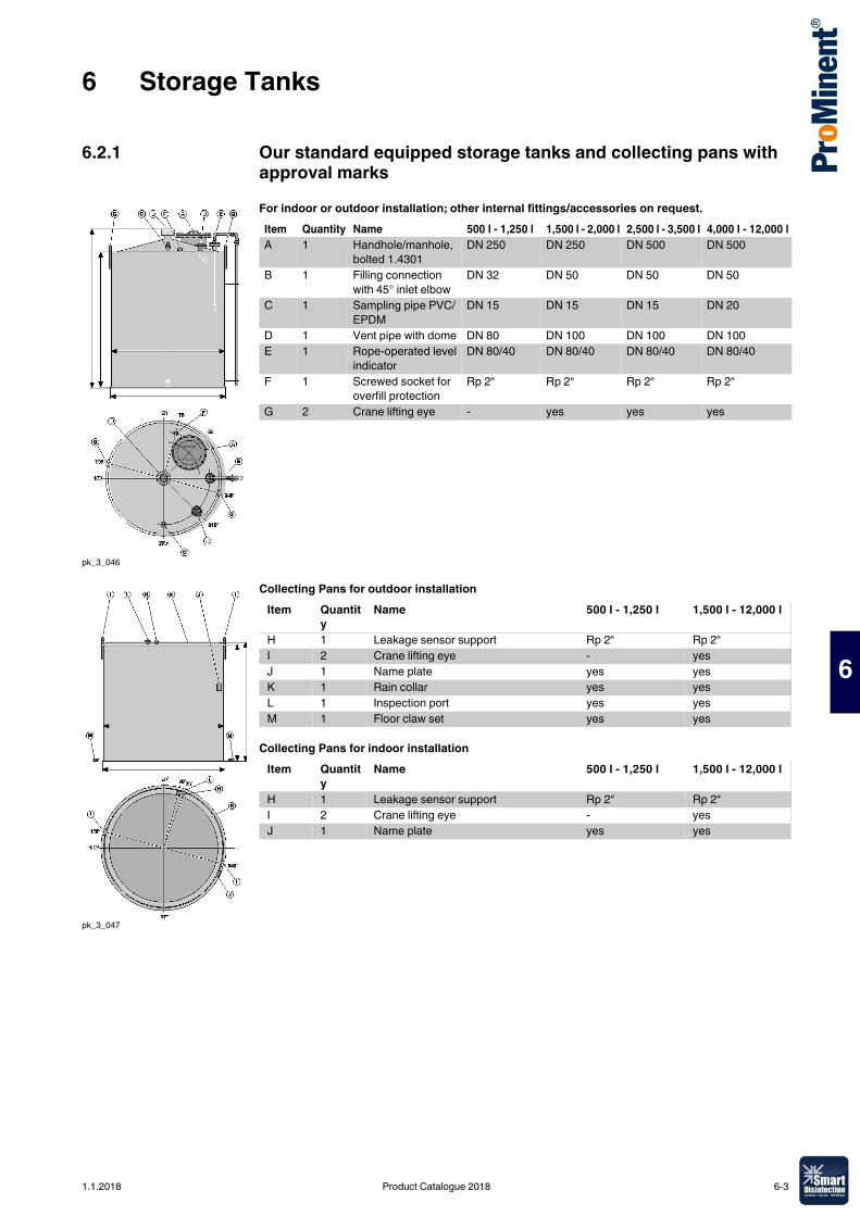
6 Storage Tanks
6
6.2.1 Our standard equipped storage tanks and collecting pans with approval marksFor indoor or outdoor installation; other internal fittings/accessories on request.
Collecting Pans for outdoor installation
Collecting Pans for indoor installation
pk_3_046
Item Quantity Name 500 l - 1,250 l 1,500 l - 2,000 l 2,500 l - 3,500 l 4,000 l - 12,000 lA 1 Handhole/manhole,
bolted 1.4301DN 250 DN 250 DN 500 DN 500
B 1 Filling connection with 45° inlet elbow
DN 32 DN 50 DN 50 DN 50
C 1 Sampling pipe PVC/EPDM
DN 15 DN 15 DN 15 DN 20
D 1 Vent pipe with dome DN 80 DN 100 DN 100 DN 100E 1 Rope-operated level
indicatorDN 80/40 DN 80/40 DN 80/40 DN 80/40
F 1 Screwed socket for overfill protection
Rp 2“ Rp 2“ Rp 2“ Rp 2“
G 2 Crane lifting eye - yes yes yes
pk_3_047
Item Quantity
Name 500 l - 1,250 l 1,500 l - 12,000 l
H 1 Leakage sensor support Rp 2“ Rp 2“I 2 Crane lifting eye - yesJ 1 Name plate yes yesK 1 Rain collar yes yesL 1 Inspection port yes yesM 1 Floor claw set yes yes
Item Quantity
Name 500 l - 1,250 l 1,500 l - 12,000 l
H 1 Leakage sensor support Rp 2“ Rp 2“I 2 Crane lifting eye - yesJ 1 Name plate yes yes
1.1.2018 Product Catalogue 2018 6-3
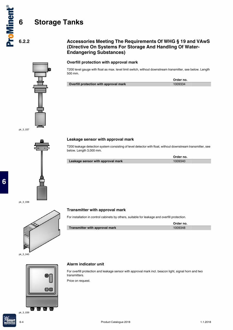
6 Storage Tanks
6
6.2.2 Accessories Meeting The Requirements Of WHG § 19 and VAwS (Directive On Systems For Storage And Handling Of Water-Endangering Substances)Overfill protection with approval markT200 level gauge with float as max. level limit switch, without downstream transmitter, see below. Length 500 mm.
Leakage sensor with approval markT200 leakage detection system consisting of level detector with float, without downstream transmitter, see below. Length 3,000 mm.
Transmitter with approval markFor installation in control cabinets by others, suitable for leakage and overfill protection.
Alarm indicator unitFor overfill protection and leakage sensor with approval mark incl. beacon light, signal horn and two transmitters.Price on request.
pk_3_037
Order no.Overfill protection with approval mark 1009334
pk_3_038
Order no.Leakage sensor with approval mark 1009340
pk_3_040
Order no.Transmitter with approval mark 1009348
pk_3_039
6-4 Product Catalogue 2018 1.1.2018
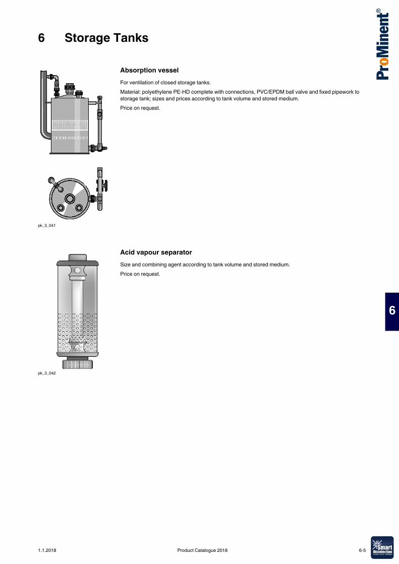
6 Storage Tanks
6
Absorption vesselFor ventilation of closed storage tanks.Material: polyethylene PE-HD complete with connections, PVC/EPDM ball valve and fixed pipework to storage tank; sizes and prices according to tank volume and stored medium.Price on request.
Acid vapour separatorSize and combining agent according to tank volume and stored medium.Price on request.
pk_3_041
pk_3_042
1.1.2018 Product Catalogue 2018 6-5
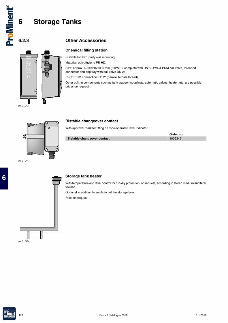
6 Storage Tanks
6
6.2.3 Other AccessoriesChemical filling stationSuitable for third-party wall mounting.Material: polyethylene PE-HD.Size: approx. 420x420x1000 mm (LxWxH), complete with DN 50 PVC/EPDM ball valve, threaded connector and drip tray with ball valve DN 25PVC/EPDM connection: Rp 2“ (parallel female thread)Other built-in components such as tank waggon couplings, automatic valves, heater, etc. are possible; prices on request.
Bistable changeover contactWith approval mark for fitting on rope-operated level indicator.
Storage tank heaterWith temperature and level control for run-dry protection; on request, according to stored medium and tank volume.Optional in addition to insulation of the storage tank.Price on request.
pk_3_043
pk_3_044
Order no.Bistable changeover contact 1009349
pk_3_045
6-6 Product Catalogue 2018 1.1.2018
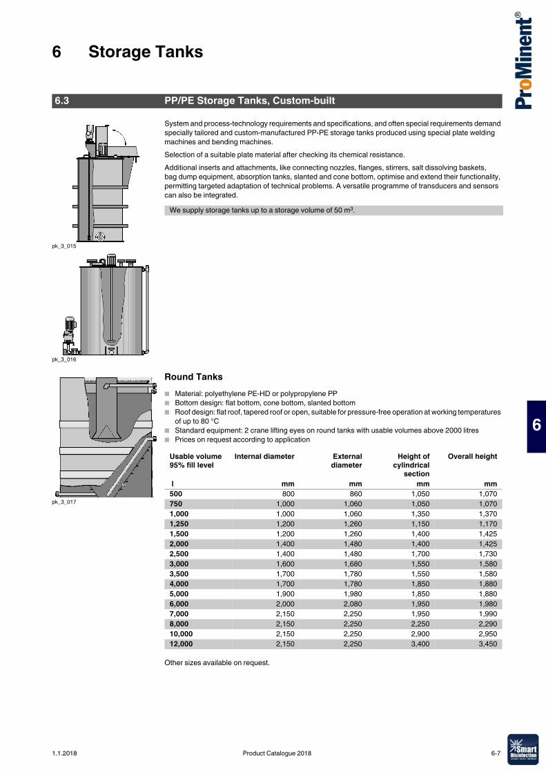
6 Storage Tanks
6
System and process-technology requirements and specifications, and often special requirements demand specially tailored and custom-manufactured PP-PE storage tanks produced using special plate welding machines and bending machines.Selection of a suitable plate material after checking its chemical resistance.Additional inserts and attachments, like connecting nozzles, flanges, stirrers, salt dissolving baskets, bag dump equipment, absorption tanks, slanted and cone bottom, optimise and extend their functionality, permitting targeted adaptation of technical problems. A versatile programme of transducers and sensors can also be integrated.
Round Tanks� Material: polyethylene PE-HD or polypropylene PP� Bottom design: flat bottom, cone bottom, slanted bottom� Roof design: flat roof, tapered roof or open, suitable for pressure-free operation at working temperatures
of up to 80 °C� Standard equipment: 2 crane lifting eyes on round tanks with usable volumes above 2000 litres� Prices on request according to application
Other sizes available on request.
6.3 PP/PE Storage Tanks, Custom-built
pk_3_015
pk_3_016
We supply storage tanks up to a storage volume of 50 m3.
pk_3_017
Usable volume 95% fill level
Internal diameter Externaldiameter
Height ofcylindrical
section
Overall height
l mm mm mm mm500 800 860 1,050 1,070750 1,000 1,060 1,050 1,0701,000 1,000 1,060 1,350 1,3701,250 1,200 1,260 1,150 1,1701,500 1,200 1,260 1,400 1,4252,000 1,400 1,480 1,400 1,4252,500 1,400 1,480 1,700 1,7303,000 1,600 1,680 1,550 1,5803,500 1,700 1,780 1,550 1,5804,000 1,700 1,780 1,850 1,8805,000 1,900 1,980 1,850 1,8806,000 2,000 2,080 1,950 1,9807,000 2,150 2,250 1,950 1,9908,000 2,150 2,250 2,250 2,29010,000 2,150 2,250 2,900 2,95012,000 2,150 2,250 3,400 3,450
1.1.2018 Product Catalogue 2018 6-7
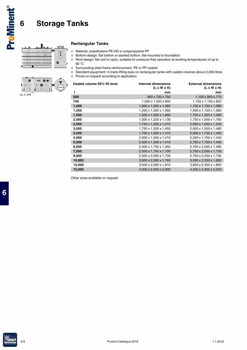
6 Storage Tanks
6
Rectangular Tanks� Material: polyethylene PE-HD or polypropylene PP� Bottom design: flat bottom or slanted bottom, flat-mounted to foundation � Roof design: flat roof or open, suitable for pressure-free operation at working temperatures of up to
80 °C� Surrounding steel frame reinforcement, PE or PP coated� Standard equipment: 4 crane lifting eyes on rectangular tanks with usable volumes above 2,000 litres.� Prices on request according to application
Other sizes available on request.
pk_3_048
Usable volume 95% fill level Internal dimensions(L x W x H)
External dimensions(L x W x H)
l mm mm500 950 x 750 x 750 1,100 x 900 x 770750 1,000 x 1,000 x 800 1,150 x 1,150 x 8201,000 1,000 x 1,000 x 1,060 1,150 x 1,150 x 1,0801,250 1,250 x 1,000 x 1,060 1,400 x 1,150 x 1,0801,500 1,500 x 1,000 x 1,060 1,750 x 1,250 x 1,0902,000 1,500 x 1,250 x 1,130 1,750 x 1,500 x 1,1602,500 1,750 x 1,250 x 1,210 2,000 x 1,500 x 1,2403,000 1,750 x 1,250 x 1,450 2,000 x 1,500 x 1,4803,500 1,750 x 1,500 x 1,410 2,000 x 1,750 x 1,4404,000 2,000 x 1,500 x 1,410 2,250 x 1,750 x 1,4405,000 2,500 x 1,500 x 1,410 2,750 x 1,750 x 1,4406,000 2,500 x 1,750 x 1,450 2,750 x 2,000 x 1,4807,000 2,500 x 1,750 x 1,700 2,750 x 2,000 x 1,7308,000 2,500 x 2,000 x 1,700 2,750 x 2,250 x 1,73010,000 3,000 x 2,000 x 1,760 3,350 x 2,350 x 1,80012,000 3,500 x 2,000 x 1,810 3,850 x 2,350 x 1,85015,000 4,000 x 2,000 x 2,000 4,350 x 2,350 x 2,050
6-8 Product Catalogue 2018 1.1.2018
7 Polymer preparation and metering systems Ultromat®, PolyRex and POLYMORE
7
7.0.1Product Catalogue 2018
The use of polyelectrolytes as flocculation aids is characterised by an extensive field of applications. They can be used in all applications where colloidal solids need to be economically separated from liquids.Our preparation and metering systems have been designed specifically for the production of ordinary or standard solutions of synthetic polyelectrolytes in powdered or liquid form and have proved themselves many times over.The experts in waste water treatment at ProMinent understand how to provide the efficient technology to implement this specialist application. They have developed systems for the most stringent requirements, which are also very easy to assemble and operate.ProMinent also provides all the advice needed for the efficient operation of a polymer batching and metering system:� Evaluation of the situation on site by trained, expert field sales staff.� Project planning of the system.� Commissioning and system maintenance by our trained service technicians.
7.1 Polyelectrolytes in Water Treatment
1.1.2018 Product Catalogue 2018 7-1
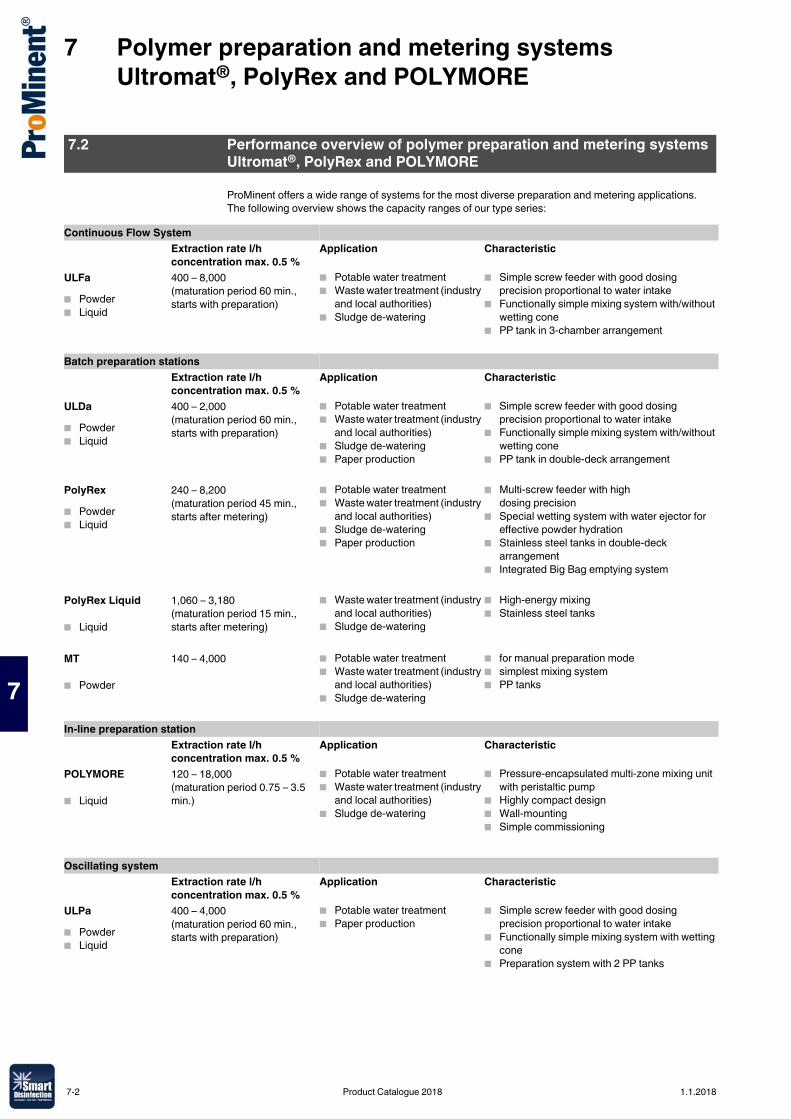
7 Polymer preparation and metering systems Ultromat®, PolyRex and POLYMORE
7
ProMinent offers a wide range of systems for the most diverse preparation and metering applications. The following overview shows the capacity ranges of our type series:
7.2 Performance overview of polymer preparation and metering systems Ultromat®, PolyRex and POLYMORE
Continuous Flow SystemExtraction rate l/hconcentration max. 0.5 %
Application Characteristic
ULFa� Powder� Liquid
400 – 8,000(maturation period 60 min., starts with preparation)
� Potable water treatment� Waste water treatment (industry
and local authorities)� Sludge de-watering
� Simple screw feeder with good dosing precision proportional to water intake
� Functionally simple mixing system with/without wetting cone
� PP tank in 3-chamber arrangement
Batch preparation stationsExtraction rate l/hconcentration max. 0.5 %
Application Characteristic
ULDa� Powder� Liquid
400 – 2,000(maturation period 60 min., starts with preparation)
� Potable water treatment� Waste water treatment (industry
and local authorities)� Sludge de-watering� Paper production
� Simple screw feeder with good dosing precision proportional to water intake
� Functionally simple mixing system with/without wetting cone
� PP tank in double-deck arrangement
PolyRex� Powder� Liquid
240 – 8,200(maturation period 45 min., starts after metering)
� Potable water treatment� Waste water treatment (industry
and local authorities)� Sludge de-watering� Paper production
� Multi-screw feeder with high dosing precision
� Special wetting system with water ejector for effective powder hydration
� Stainless steel tanks in double-deck arrangement
� Integrated Big Bag emptying system
PolyRex Liquid
� Liquid
1,060 – 3,180(maturation period 15 min., starts after metering)
� Waste water treatment (industry and local authorities)
� Sludge de-watering
� High-energy mixing� Stainless steel tanks
MT
� Powder
140 – 4,000 � Potable water treatment� Waste water treatment (industry
and local authorities)� Sludge de-watering
� for manual preparation mode� simplest mixing system� PP tanks
In-line preparation stationExtraction rate l/hconcentration max. 0.5 %
Application Characteristic
POLYMORE
� Liquid
120 – 18,000(maturation period 0.75 – 3.5 min.)
� Potable water treatment� Waste water treatment (industry
and local authorities)� Sludge de-watering
� Pressure-encapsulated multi-zone mixing unit with peristaltic pump
� Highly compact design� Wall-mounting� Simple commissioning
Oscillating systemExtraction rate l/hconcentration max. 0.5 %
Application Characteristic
ULPa� Powder� Liquid
400 – 4,000(maturation period 60 min., starts with preparation)
� Potable water treatment� Paper production
� Simple screw feeder with good dosing precision proportional to water intake
� Functionally simple mixing system with wetting cone
� Preparation system with 2 PP tanks
7-2 Product Catalogue 2018 1.1.2018
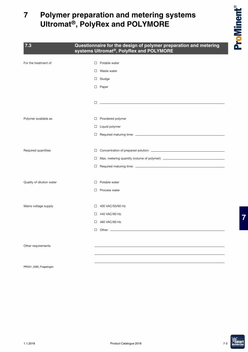
7 Polymer preparation and metering systems Ultromat®, PolyRex and POLYMORE
7
PRO01_0285_Fragebogen
7.3 Questionnaire for the design of polymer preparation and metering systems Ultromat®, PolyRex and POLYMORE
For the treatment of Potable water
Waste water
Sludge
Paper
Polymer available as Powdered polymer
Liquid polymer
Required maturing time:
Required quantities Concentration of prepared solution:
Max. metering quantity (volume of polymer):
Required maturing time:
Quality of dilution water Potable water
Process water
Mains voltage supply 400 VAC/50/60 Hz
440 VAC/60 Hz
460 VAC/60 Hz
Other:
Other requirements
1.1.2018 Product Catalogue 2018 7-3
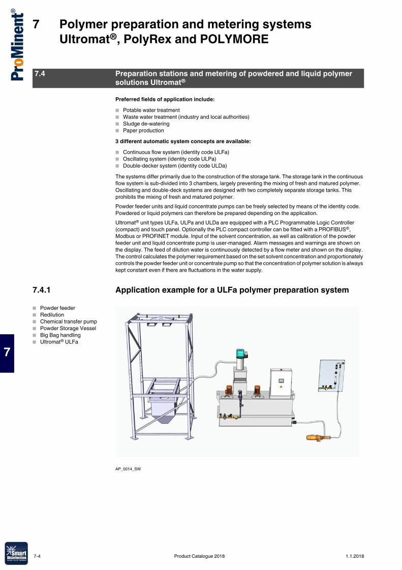
7 Polymer preparation and metering systems Ultromat®, PolyRex and POLYMORE
7
Preferred fields of application include:� Potable water treatment� Waste water treatment (industry and local authorities)� Sludge de-watering� Paper production3 different automatic system concepts are available:� Continuous flow system (identity code ULFa)� Oscillating system (identity code ULPa)� Double-decker system (identity code ULDa)The systems differ primarily due to the construction of the storage tank. The storage tank in the continuous flow system is sub-divided into 3 chambers, largely preventing the mixing of fresh and matured polymer. Oscillating and double-deck systems are designed with two completely separate storage tanks. This prohibits the mixing of fresh and matured polymer.Powder feeder units and liquid concentrate pumps can be freely selected by means of the identity code. Powdered or liquid polymers can therefore be prepared depending on the application.Ultromat® unit types ULFa, ULPa and ULDa are equipped with a PLC Programmable Logic Controller (compact) and touch panel. Optionally the PLC compact controller can be fitted with a PROFIBUS®, Modbus or PROFINET module. Input of the solvent concentration, as well as calibration of the powder feeder unit and liquid concentrate pump is user-managed. Alarm messages and warnings are shown on the display. The feed of dilution water is continuously detected by a flow meter and shown on the display. The control calculates the polymer requirement based on the set solvent concentration and proportionately controls the powder feeder unit or concentrate pump so that the concentration of polymer solution is always kept constant even if there are fluctuations in the water supply.
7.4.1 Application example for a ULFa polymer preparation system
AP_0014_SW
7.4 Preparation stations and metering of powdered and liquid polymer solutions Ultromat®
� Powder feeder� Redilution� Chemical transfer pump� Powder Storage Vessel� Big Bag handling� Ultromat® ULFa
7-4 Product Catalogue 2018 1.1.2018
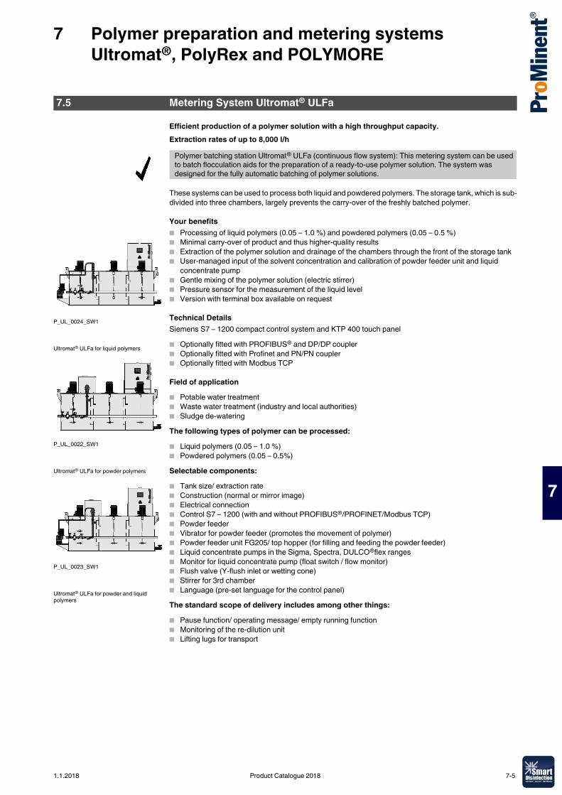
7 Polymer preparation and metering systems Ultromat®, PolyRex and POLYMORE
7
Efficient production of a polymer solution with a high throughput capacity.Extraction rates of up to 8,000 l/h
These systems can be used to process both liquid and powdered polymers. The storage tank, which is sub-divided into three chambers, largely prevents the carry-over of the freshly batched polymer.
Your benefits� Processing of liquid polymers (0.05 – 1.0 %) and powdered polymers (0.05 – 0.5 %)� Minimal carry-over of product and thus higher-quality results� Extraction of the polymer solution and drainage of the chambers through the front of the storage tank� User-managed input of the solvent concentration and calibration of powder feeder unit and liquid
concentrate pump� Gentle mixing of the polymer solution (electric stirrer)� Pressure sensor for the measurement of the liquid level� Version with terminal box available on request
Technical DetailsSiemens S7 – 1200 compact control system and KTP 400 touch panel� Optionally fitted with PROFIBUS® and DP/DP coupler� Optionally fitted with Profinet and PN/PN coupler� Optionally fitted with Modbus TCP
Field of application� Potable water treatment� Waste water treatment (industry and local authorities)� Sludge de-wateringThe following types of polymer can be processed:� Liquid polymers (0.05 – 1.0 %)� Powdered polymers (0.05 – 0.5%)Selectable components:� Tank size/ extraction rate� Construction (normal or mirror image)� Electrical connection� Control S7 – 1200 (with and without PROFIBUS®/PROFINET/Modbus TCP)� Powder feeder� Vibrator for powder feeder (promotes the movement of polymer)� Powder feeder unit FG205/ top hopper (for filling and feeding the powder feeder)� Liquid concentrate pumps in the Sigma, Spectra, DULCO®flex ranges� Monitor for liquid concentrate pump (float switch / flow monitor)� Flush valve (Y-flush inlet or wetting cone)� Stirrer for 3rd chamber� Language (pre-set language for the control panel)The standard scope of delivery includes among other things:� Pause function/ operating message/ empty running function� Monitoring of the re-dilution unit� Lifting lugs for transport
7.5 Metering System Ultromat® ULFa
Polymer batching station Ultromat® ULFa (continuous flow system): This metering system can be used to batch flocculation aids for the preparation of a ready-to-use polymer solution. The system was designed for the fully automatic batching of polymer solutions.
P_UL_0024_SW1
P_UL_0022_SW1
P_UL_0023_SW1
Ultromat® ULFa for liquid polymers
Ultromat® ULFa for powder polymers
Ultromat® ULFa for powder and liquid polymers
1.1.2018 Product Catalogue 2018 7-5
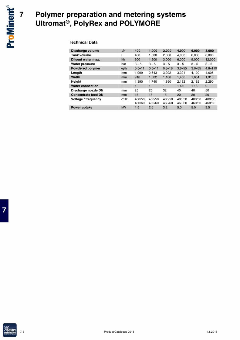
7 Polymer preparation and metering systems Ultromat®, PolyRex and POLYMORE
7
Technical DataDischarge volume l/h 400 1,000 2,000 4,000 6,000 8,000Tank volume l 400 1,000 2,000 4,000 6,000 8,000Diluent water max. l/h 600 1,500 3,000 6,000 9,000 12,000Water pressure bar 3 – 5 3 – 5 3 – 5 3 – 5 3 – 5 3 – 5Powdered polymer kg/h 0.5–11 0.5–11 0.8–18 3.6–55 3.6–55 4.8–110Length mm 1,999 2,643 3,292 3,301 4,120 4,605Width mm 918 1,002 1,186 1,456 1,651 1,910Height mm 1,390 1,740 1,890 2,182 2,182 2,290Water connection " 1 1 1 1 1/2 1 1/2 2Discharge nozzle DN mm 25 25 32 40 40 50Concentrate feed DN mm 15 15 15 20 20 20Voltage / frequency V/Hz 400/50
460/60400/50460/60
400/50460/60
400/50460/60
400/50460/60
400/50460/60
Power uptake kW 1.5 2.6 3.2 5.0 5.0 9.5
7-6 Product Catalogue 2018 1.1.2018
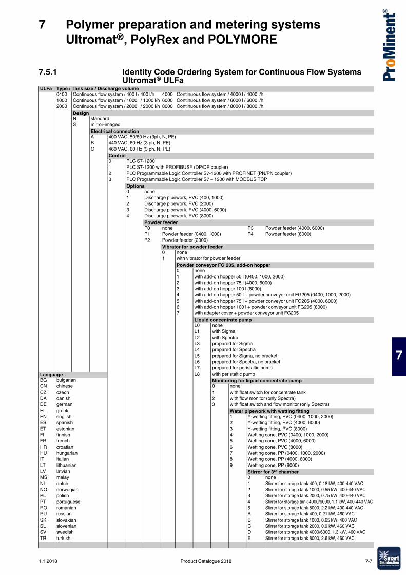
7 Polymer preparation and metering systems Ultromat®, PolyRex and POLYMORE
7
7.5.1 Identity Code Ordering System for Continuous Flow Systems Ultromat® ULFa
ULFa Type / Tank size / Discharge volume0400 Continuous flow system / 400 l / 400 l/h 4000 Continuous flow system / 4000 l / 4000 l/h1000 Continuous flow system / 1000 l / 1000 l/h 6000 Continuous flow system / 6000 l / 6000 l/h2000 Continuous flow system / 2000 l / 2000 l/h 8000 Continuous flow system / 8000 l / 8000 l/h
DesignN standardS mirror-imaged
Electrical connectionA 400 VAC, 50/60 Hz (3ph, N, PE)B 440 VAC, 60 Hz (3 ph, N, PE)C 460 VAC, 60 Hz (3 ph, N, PE)
Control0 PLC S7-12001 PLC S7-1200 with PROFIBUS® (DP/DP coupler)2 PLC Programmable Logic Controller S7-1200 with PROFINET (PN/PN coupler)3 PLC Programmable Logic Controller S7 – 1200 with MODBUS TCP
Options0 none1 Discharge pipework, PVC (400, 1000)2 Discharge pipework, PVC (2000)3 Discharge pipework, PVC (4000, 6000)4 Discharge pipework, PVC (8000)
Powder feederP0 none P3 Powder feeder (4000, 6000)P1 Powder feeder (0400, 1000) P4 Powder feeder (8000)P2 Powder feeder (2000)
Vibrator for powder feeder0 none1 with vibrator for powder feeder
Powder conveyor FG 205, add-on hopper0 none1 with add-on hopper 50 l (0400, 1000, 2000)2 with add-on hopper 75 l (4000, 6000)3 with add-on hopper 100 l (8000)4 with add-on hopper 50 l + powder conveyor unit FG205 (0400, 1000, 2000)5 with add-on hopper 75 l + powder conveyor unit FG205 (4000, 6000)6 with add-on hopper 100 l + powder conveyor unit FG205 (8000)7 with adapter cover + powder conveyor unit FG205
Liquid concentrate pumpL0 noneL1 with SigmaL2 with SpectraL3 prepared for SigmaL4 prepared for SpectraL5 prepared for Sigma, no bracketL6 prepared for Spectra, no bracketL7 prepared for peristaltic pump
Language L8 with peristaltic pumpBG bulgarian Monitoring for liquid concentrate pumpCN chinese 0 noneCZ czech 1 with float switch for concentrate tankDA danish 2 with flow monitor (only Spectra)DE german 3 with float switch and flow monitor (only Spectra)EL greek Water pipework with wetting fittingEN english 1 Y-wetting fitting, PVC (0400, 1000, 2000)ES spanish 2 Y-wetting fitting, PVC (4000, 6000)ET estonian 3 Y-wetting fitting, PVC (8000)FI finnish 4 Wetting cone, PVC (0400, 1000, 2000)FR french 5 Wetting cone, PVC (4000, 6000)HR croatian 6 Wetting cone, PVC (8000)HU hungarian 7 Wetting cone, PP (0400, 1000, 2000)IT italian 8 Wetting cone, PP (4000, 6000)LT lithuanian 9 Wetting cone, PP (8000)LV latvian Stirrer for 3rd chamberMS malay 0 noneNL dutch 1 Stirrer for storage tank 400, 0.18 kW, 400-440 VACNO norwegian 2 Stirrer for storage tank 1000, 0.55 kW, 400-440 VACPL polish 3 Stirrer for storage tank 2000, 0.75 kW, 400-440 VACPT portuguese 4 Stirrer for storage tank 4000/6000, 1.1 kW, 400-440 VACRO romanian 5 Stirrer for storage tank 8000, 2.2 kW, 400-440 VACRU russian A Stirrer for storage tank 400, 0.21 kW, 460 VACSK slovakian B Stirrer for storage tank 1000, 0.65 kW, 460 VACSL slovenian C Stirrer for storage tank 2000, 0.9 kW, 460 VACSV swedish D Stirrer for storage tank 4000/6000, 1.3 kW, 460 VACTR turkish E Stirrer for storage tank 8000, 2.6 kW, 460 VAC
1.1.2018 Product Catalogue 2018 7-7
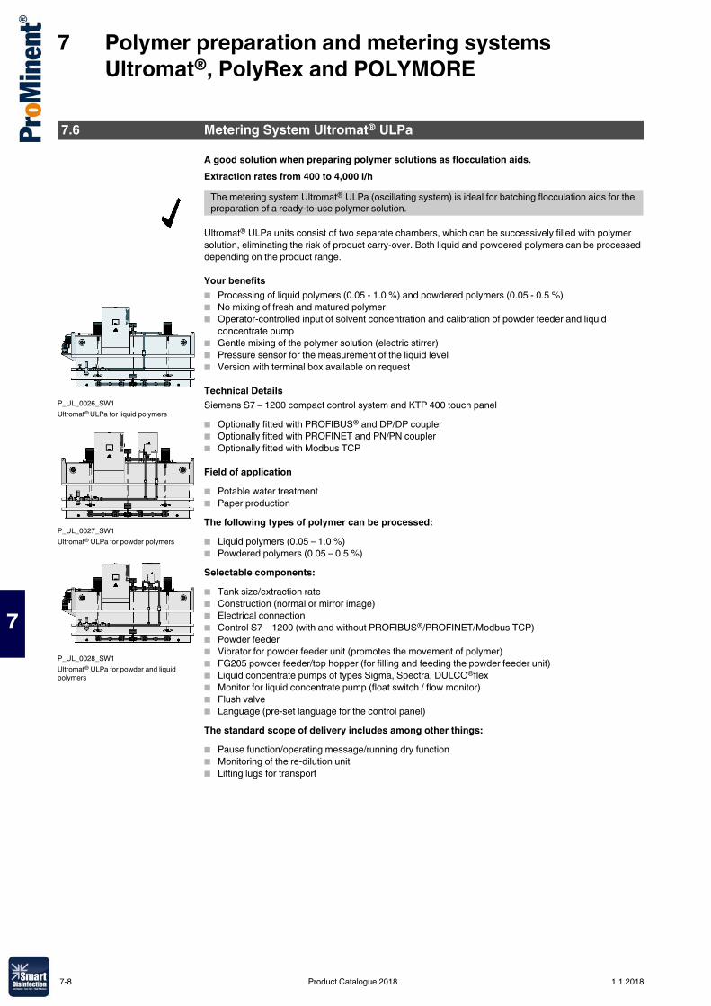
7 Polymer preparation and metering systems Ultromat®, PolyRex and POLYMORE
7
A good solution when preparing polymer solutions as flocculation aids.Extraction rates from 400 to 4,000 l/h
Ultromat® ULPa units consist of two separate chambers, which can be successively filled with polymer solution, eliminating the risk of product carry-over. Both liquid and powdered polymers can be processed depending on the product range.
Your benefits� Processing of liquid polymers (0.05 - 1.0 %) and powdered polymers (0.05 - 0.5 %)� No mixing of fresh and matured polymer� Operator-controlled input of solvent concentration and calibration of powder feeder and liquid
concentrate pump� Gentle mixing of the polymer solution (electric stirrer)� Pressure sensor for the measurement of the liquid level� Version with terminal box available on request
Technical DetailsSiemens S7 – 1200 compact control system and KTP 400 touch panel� Optionally fitted with PROFIBUS® and DP/DP coupler� Optionally fitted with PROFINET and PN/PN coupler� Optionally fitted with Modbus TCP
Field of application� Potable water treatment� Paper productionThe following types of polymer can be processed:� Liquid polymers (0.05 – 1.0 %)� Powdered polymers (0.05 – 0.5 %)Selectable components:� Tank size/extraction rate� Construction (normal or mirror image)� Electrical connection� Control S7 – 1200 (with and without PROFIBUS®/PROFINET/Modbus TCP)� Powder feeder� Vibrator for powder feeder unit (promotes the movement of polymer)� FG205 powder feeder/top hopper (for filling and feeding the powder feeder unit)� Liquid concentrate pumps of types Sigma, Spectra, DULCO®flex� Monitor for liquid concentrate pump (float switch / flow monitor)� Flush valve� Language (pre-set language for the control panel)The standard scope of delivery includes among other things:� Pause function/operating message/running dry function� Monitoring of the re-dilution unit� Lifting lugs for transport
7.6 Metering System Ultromat® ULPa
The metering system Ultromat® ULPa (oscillating system) is ideal for batching flocculation aids for the preparation of a ready-to-use polymer solution.
P_UL_0026_SW1Ultromat® ULPa for liquid polymers
P_UL_0027_SW1Ultromat® ULPa for powder polymers
P_UL_0028_SW1Ultromat® ULPa for powder and liquid polymers
7-8 Product Catalogue 2018 1.1.2018
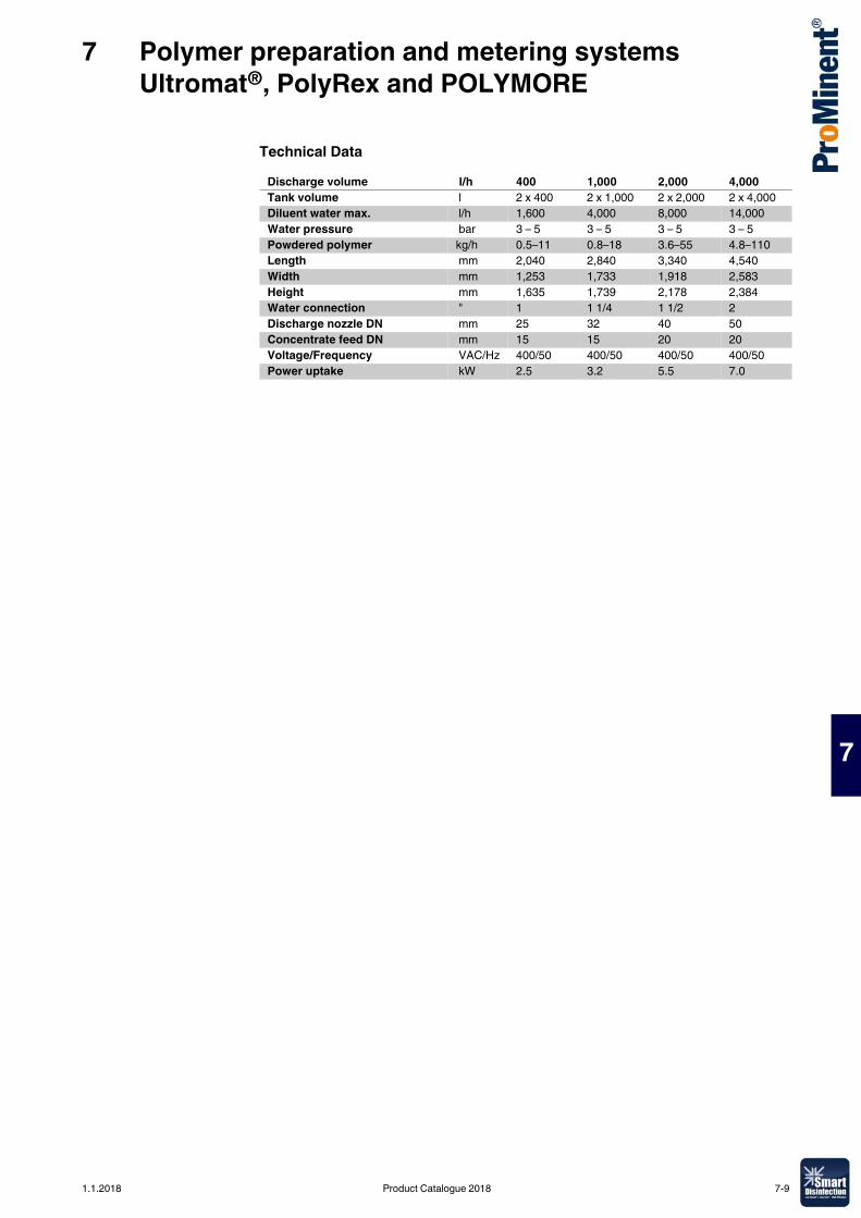
7 Polymer preparation and metering systems Ultromat®, PolyRex and POLYMORE
7
Technical DataDischarge volume l/h 400 1,000 2,000 4,000Tank volume l 2 x 400 2 x 1,000 2 x 2,000 2 x 4,000Diluent water max. l/h 1,600 4,000 8,000 14,000Water pressure bar 3 – 5 3 – 5 3 – 5 3 – 5Powdered polymer kg/h 0.5–11 0.8–18 3.6–55 4.8–110Length mm 2,040 2,840 3,340 4,540Width mm 1,253 1,733 1,918 2,583Height mm 1,635 1,739 2,178 2,384Water connection " 1 1 1/4 1 1/2 2Discharge nozzle DN mm 25 32 40 50Concentrate feed DN mm 15 15 20 20Voltage/Frequency VAC/Hz 400/50 400/50 400/50 400/50Power uptake kW 2.5 3.2 5.5 7.0
1.1.2018 Product Catalogue 2018 7-9
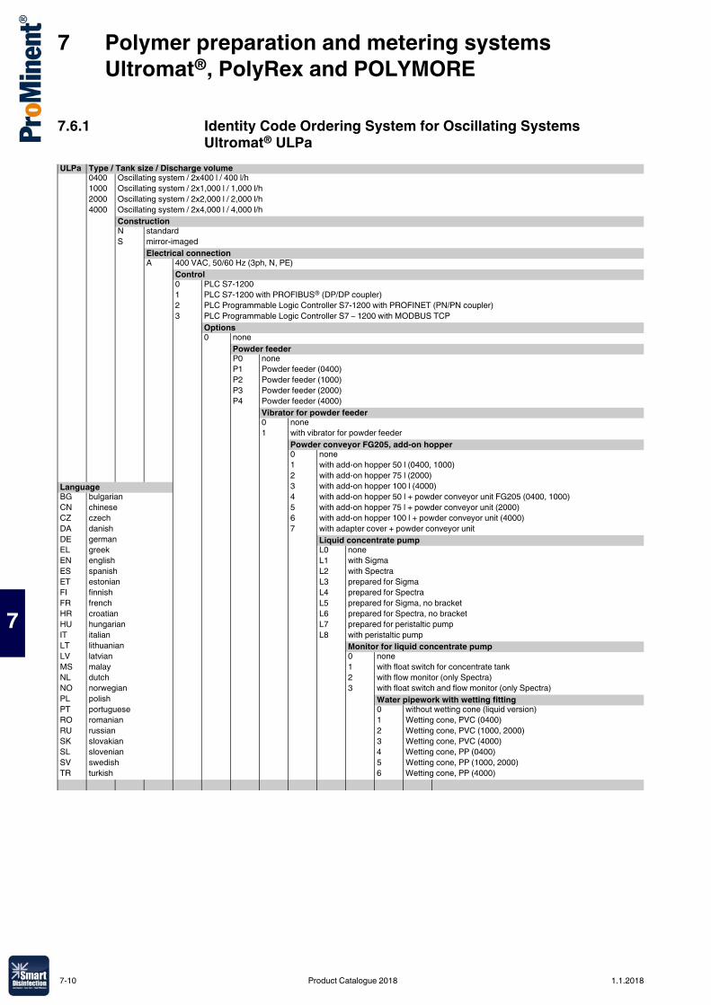
7 Polymer preparation and metering systems Ultromat®, PolyRex and POLYMORE
7
7.6.1 Identity Code Ordering System for Oscillating Systems Ultromat® ULPa
ULPa Type / Tank size / Discharge volume0400 Oscillating system / 2x400 l / 400 l/h1000 Oscillating system / 2x1,000 l / 1,000 l/h2000 Oscillating system / 2x2,000 l / 2,000 l/h4000 Oscillating system / 2x4,000 l / 4,000 l/h
ConstructionN standardS mirror-imaged
Electrical connectionA 400 VAC, 50/60 Hz (3ph, N, PE)
Control0 PLC S7-12001 PLC S7-1200 with PROFIBUS® (DP/DP coupler)2 PLC Programmable Logic Controller S7-1200 with PROFINET (PN/PN coupler)3 PLC Programmable Logic Controller S7 – 1200 with MODBUS TCP
Options0 none
Powder feederP0 noneP1 Powder feeder (0400)P2 Powder feeder (1000)P3 Powder feeder (2000)P4 Powder feeder (4000)
Vibrator for powder feeder0 none1 with vibrator for powder feeder
Powder conveyor FG205, add-on hopper0 none1 with add-on hopper 50 l (0400, 1000)2 with add-on hopper 75 l (2000)
Language 3 with add-on hopper 100 l (4000)BG bulgarian 4 with add-on hopper 50 l + powder conveyor unit FG205 (0400, 1000)CN chinese 5 with add-on hopper 75 l + powder conveyor unit (2000)CZ czech 6 with add-on hopper 100 l + powder conveyor unit (4000)DA danish 7 with adapter cover + powder conveyor unitDE german Liquid concentrate pumpEL greek L0 noneEN english L1 with SigmaES spanish L2 with SpectraET estonian L3 prepared for SigmaFI finnish L4 prepared for SpectraFR french L5 prepared for Sigma, no bracketHR croatian L6 prepared for Spectra, no bracketHU hungarian L7 prepared for peristaltic pumpIT italian L8 with peristaltic pumpLT lithuanian Monitor for liquid concentrate pumpLV latvian 0 noneMS malay 1 with float switch for concentrate tankNL dutch 2 with flow monitor (only Spectra)NO norwegian 3 with float switch and flow monitor (only Spectra)PL polish Water pipework with wetting fittingPT portuguese 0 without wetting cone (liquid version)RO romanian 1 Wetting cone, PVC (0400)RU russian 2 Wetting cone, PVC (1000, 2000)SK slovakian 3 Wetting cone, PVC (4000)SL slovenian 4 Wetting cone, PP (0400)SV swedish 5 Wetting cone, PP (1000, 2000)TR turkish 6 Wetting cone, PP (4000)
7-10 Product Catalogue 2018 1.1.2018
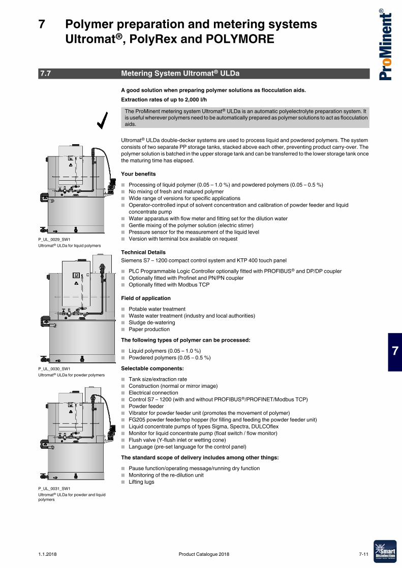
7 Polymer preparation and metering systems Ultromat®, PolyRex and POLYMORE
7
A good solution when preparing polymer solutions as flocculation aids.Extraction rates of up to 2,000 l/h
Ultromat® ULDa double-decker systems are used to process liquid and powdered polymers. The system consists of two separate PP storage tanks, stacked above each other, preventing product carry-over. The polymer solution is batched in the upper storage tank and can be transferred to the lower storage tank once the maturing time has elapsed.
Your benefits� Processing of liquid polymer (0.05 – 1.0 %) and powdered polymers (0.05 – 0.5 %)� No mixing of fresh and matured polymer� Wide range of versions for specific applications� Operator-controlled input of solvent concentration and calibration of powder feeder and liquid
concentrate pump� Water apparatus with flow meter and fitting set for the dilution water� Gentle mixing of the polymer solution (electric stirrer)� Pressure sensor for the measurement of the liquid level� Version with terminal box available on request
Technical DetailsSiemens S7 – 1200 compact control system and KTP 400 touch panel� PLC Programmable Logic Controller optionally fitted with PROFIBUS® and DP/DP coupler� Optionally fitted with Profinet and PN/PN coupler� Optionally fitted with Modbus TCP
Field of application� Potable water treatment� Waste water treatment (industry and local authorities)� Sludge de-watering� Paper productionThe following types of polymer can be processed:� Liquid polymers (0.05 – 1.0 %)� Powdered polymers (0.05 – 0.5 %)Selectable components:� Tank size/extraction rate� Construction (normal or mirror image)� Electrical connection� Control S7 – 1200 (with and without PROFIBUS®/PROFINET/Modbus TCP)� Powder feeder� Vibrator for powder feeder unit (promotes the movement of polymer)� FG205 powder feeder/top hopper (for filling and feeding the powder feeder unit)� Liquid concentrate pumps of types Sigma, Spectra, DULCOflex� Monitor for liquid concentrate pump (float switch / flow monitor)� Flush valve (Y-flush inlet or wetting cone)� Language (pre-set language for the control panel)The standard scope of delivery includes among other things:� Pause function/operating message/running dry function� Monitoring of the re-dilution unit� Lifting lugs
7.7 Metering System Ultromat® ULDa
The ProMinent metering system Ultromat® ULDa is an automatic polyelectrolyte preparation system. It is useful wherever polymers need to be automatically prepared as polymer solutions to act as flocculation aids.
P_UL_0029_SW1Ultromat® ULDa for liquid polymers
P_UL_0030_SW1Ultromat® ULDa for powder polymers
P_UL_0031_SW1Ultromat® ULDa for powder and liquid polymers
1.1.2018 Product Catalogue 2018 7-11
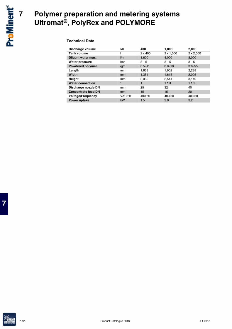
7 Polymer preparation and metering systems Ultromat®, PolyRex and POLYMORE
7
Technical DataDischarge volume l/h 400 1,000 2,000Tank volume l 2 x 400 2 x 1,000 2 x 2,000Diluent water max. l/h 1,600 4,000 8,000Water pressure bar 3 – 5 3 – 5 3 – 5Powdered polymer kg/h 0.5–11 0.8–18 3.6–55Length mm 1,638 1,902 2,288Width mm 1,351 1,615 2,005Height mm 2,030 2,514 3,149Water connection " 1 1 1/4 1 1/2Discharge nozzle DN mm 25 32 40Concentrate feed DN mm 15 15 20Voltage/Frequency VAC/Hz 400/50 400/50 400/50Power uptake kW 1.5 2.6 3.2
7-12 Product Catalogue 2018 1.1.2018
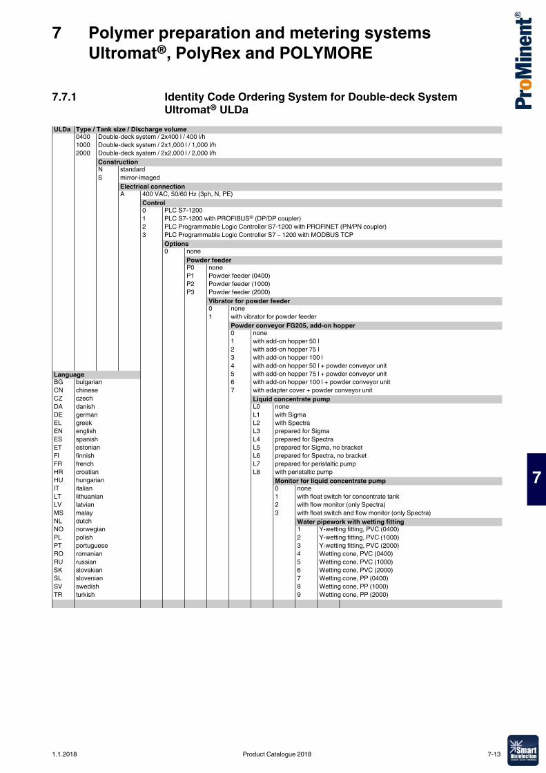
7 Polymer preparation and metering systems Ultromat®, PolyRex and POLYMORE
7
7.7.1 Identity Code Ordering System for Double-deck System Ultromat® ULDa
ULDa Type / Tank size / Discharge volume0400 Double-deck system / 2x400 l / 400 l/h1000 Double-deck system / 2x1,000 l / 1,000 l/h2000 Double-deck system / 2x2,000 l / 2,000 l/h
ConstructionN standardS mirror-imaged
Electrical connectionA 400 VAC, 50/60 Hz (3ph, N, PE)
Control0 PLC S7-12001 PLC S7-1200 with PROFIBUS® (DP/DP coupler)2 PLC Programmable Logic Controller S7-1200 with PROFINET (PN/PN coupler)3 PLC Programmable Logic Controller S7 – 1200 with MODBUS TCP
Options0 none
Powder feederP0 noneP1 Powder feeder (0400)P2 Powder feeder (1000)P3 Powder feeder (2000)
Vibrator for powder feeder0 none1 with vibrator for powder feeder
Powder conveyor FG205, add-on hopper0 none1 with add-on hopper 50 l2 with add-on hopper 75 l3 with add-on hopper 100 l4 with add-on hopper 50 l + powder conveyor unit
Language 5 with add-on hopper 75 l + powder conveyor unitBG bulgarian 6 with add-on hopper 100 l + powder conveyor unitCN chinese 7 with adapter cover + powder conveyor unitCZ czech Liquid concentrate pumpDA danish L0 noneDE german L1 with SigmaEL greek L2 with SpectraEN english L3 prepared for SigmaES spanish L4 prepared for SpectraET estonian L5 prepared for Sigma, no bracketFI finnish L6 prepared for Spectra, no bracketFR french L7 prepared for peristaltic pumpHR croatian L8 with peristaltic pumpHU hungarian Monitor for liquid concentrate pumpIT italian 0 noneLT lithuanian 1 with float switch for concentrate tankLV latvian 2 with flow monitor (only Spectra)MS malay 3 with float switch and flow monitor (only Spectra)NL dutch Water pipework with wetting fittingNO norwegian 1 Y-wetting fitting, PVC (0400)PL polish 2 Y-wetting fitting, PVC (1000)PT portuguese 3 Y-wetting fitting, PVC (2000)RO romanian 4 Wetting cone, PVC (0400)RU russian 5 Wetting cone, PVC (1000)SK slovakian 6 Wetting cone, PVC (2000)SL slovenian 7 Wetting cone, PP (0400)SV swedish 8 Wetting cone, PP (1000)TR turkish 9 Wetting cone, PP (2000)
1.1.2018 Product Catalogue 2018 7-13
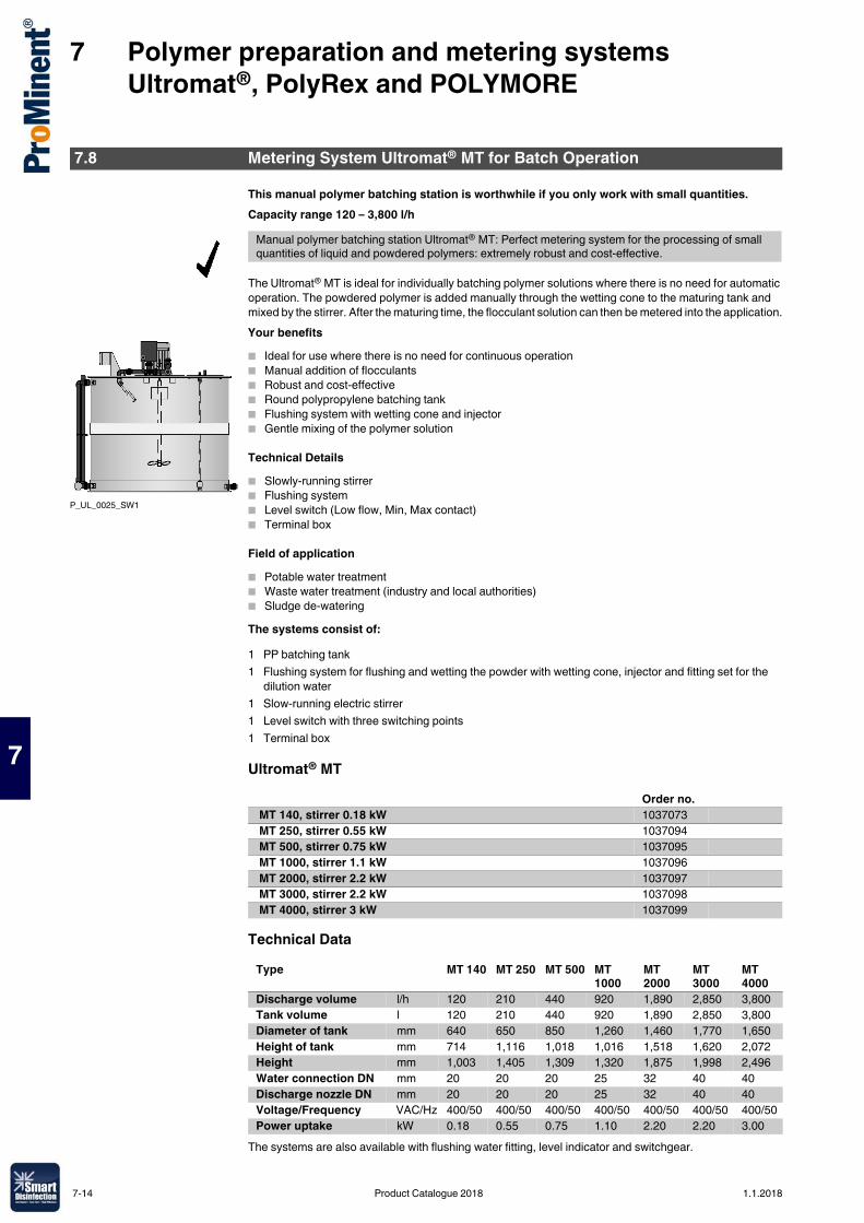
7 Polymer preparation and metering systems Ultromat®, PolyRex and POLYMORE
7
This manual polymer batching station is worthwhile if you only work with small quantities.Capacity range 120 – 3,800 l/h
The Ultromat® MT is ideal for individually batching polymer solutions where there is no need for automatic operation. The powdered polymer is added manually through the wetting cone to the maturing tank and mixed by the stirrer. After the maturing time, the flocculant solution can then be metered into the application.Your benefits� Ideal for use where there is no need for continuous operation� Manual addition of flocculants� Robust and cost-effective� Round polypropylene batching tank� Flushing system with wetting cone and injector� Gentle mixing of the polymer solution
Technical Details� Slowly-running stirrer� Flushing system� Level switch (Low flow, Min, Max contact)� Terminal box
Field of application� Potable water treatment� Waste water treatment (industry and local authorities)� Sludge de-wateringThe systems consist of:
Ultromat® MT
Technical Data
The systems are also available with flushing water fitting, level indicator and switchgear.
7.8 Metering System Ultromat® MT for Batch Operation
Manual polymer batching station Ultromat® MT: Perfect metering system for the processing of small quantities of liquid and powdered polymers: extremely robust and cost-effective.
P_UL_0025_SW1
1 PP batching tank1 Flushing system for flushing and wetting the powder with wetting cone, injector and fitting set for the
dilution water1 Slow-running electric stirrer1 Level switch with three switching points1 Terminal box
Order no. MT 140, stirrer 0.18 kW 1037073 MT 250, stirrer 0.55 kW 1037094 MT 500, stirrer 0.75 kW 1037095 MT 1000, stirrer 1.1 kW 1037096 MT 2000, stirrer 2.2 kW 1037097 MT 3000, stirrer 2.2 kW 1037098 MT 4000, stirrer 3 kW 1037099
Type MT 140 MT 250 MT 500 MT 1000
MT 2000
MT 3000
MT 4000
Discharge volume l/h 120 210 440 920 1,890 2,850 3,800Tank volume l 120 210 440 920 1,890 2,850 3,800Diameter of tank mm 640 650 850 1,260 1,460 1,770 1,650Height of tank mm 714 1,116 1,018 1,016 1,518 1,620 2,072Height mm 1,003 1,405 1,309 1,320 1,875 1,998 2,496Water connection DN mm 20 20 20 25 32 40 40Discharge nozzle DN mm 20 20 20 25 32 40 40Voltage/Frequency VAC/Hz 400/50 400/50 400/50 400/50 400/50 400/50 400/50Power uptake kW 0.18 0.55 0.75 1.10 2.20 2.20 3.00
7-14 Product Catalogue 2018 1.1.2018
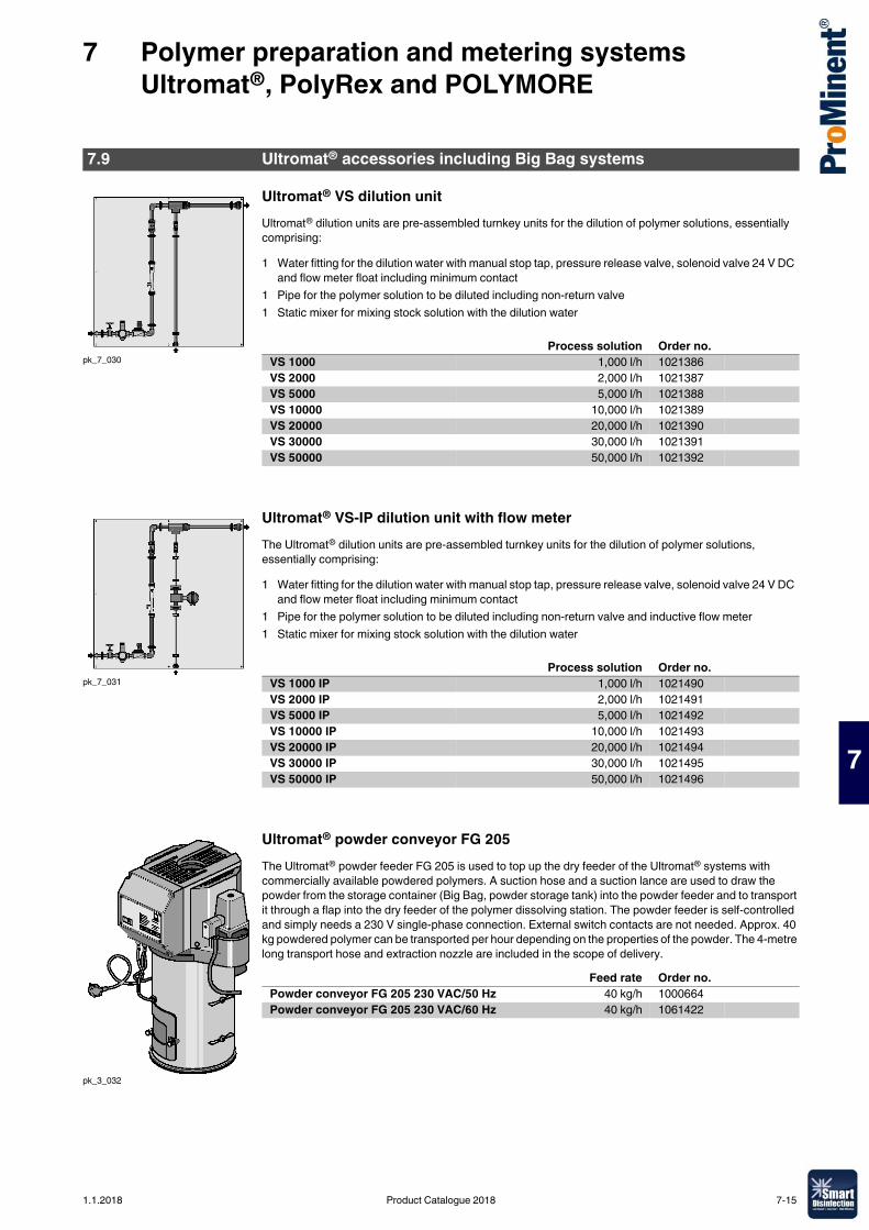
7 Polymer preparation and metering systems Ultromat®, PolyRex and POLYMORE
7
Ultromat® VS dilution unitUltromat® dilution units are pre-assembled turnkey units for the dilution of polymer solutions, essentially comprising:
Ultromat® VS-IP dilution unit with flow meterThe Ultromat® dilution units are pre-assembled turnkey units for the dilution of polymer solutions, essentially comprising:
Ultromat® powder conveyor FG 205The Ultromat® powder feeder FG 205 is used to top up the dry feeder of the Ultromat® systems with commercially available powdered polymers. A suction hose and a suction lance are used to draw the powder from the storage container (Big Bag, powder storage tank) into the powder feeder and to transport it through a flap into the dry feeder of the polymer dissolving station. The powder feeder is self-controlled and simply needs a 230 V single-phase connection. External switch contacts are not needed. Approx. 40 kg powdered polymer can be transported per hour depending on the properties of the powder. The 4-metre long transport hose and extraction nozzle are included in the scope of delivery.
7.9 Ultromat® accessories including Big Bag systems
pk_7_030
1 Water fitting for the dilution water with manual stop tap, pressure release valve, solenoid valve 24 V DC and flow meter float including minimum contact
1 Pipe for the polymer solution to be diluted including non-return valve1 Static mixer for mixing stock solution with the dilution water
Process solution Order no.VS 1000 1,000 l/h 1021386VS 2000 2,000 l/h 1021387VS 5000 5,000 l/h 1021388VS 10000 10,000 l/h 1021389VS 20000 20,000 l/h 1021390VS 30000 30,000 l/h 1021391VS 50000 50,000 l/h 1021392
pk_7_031
1 Water fitting for the dilution water with manual stop tap, pressure release valve, solenoid valve 24 V DC and flow meter float including minimum contact
1 Pipe for the polymer solution to be diluted including non-return valve and inductive flow meter1 Static mixer for mixing stock solution with the dilution water
Process solution Order no.VS 1000 IP 1,000 l/h 1021490VS 2000 IP 2,000 l/h 1021491VS 5000 IP 5,000 l/h 1021492VS 10000 IP 10,000 l/h 1021493VS 20000 IP 20,000 l/h 1021494VS 30000 IP 30,000 l/h 1021495VS 50000 IP 50,000 l/h 1021496
pk_3_032
Feed rate Order no.Powder conveyor FG 205 230 VAC/50 Hz 40 kg/h 1000664Powder conveyor FG 205 230 VAC/60 Hz 40 kg/h 1061422
1.1.2018 Product Catalogue 2018 7-15
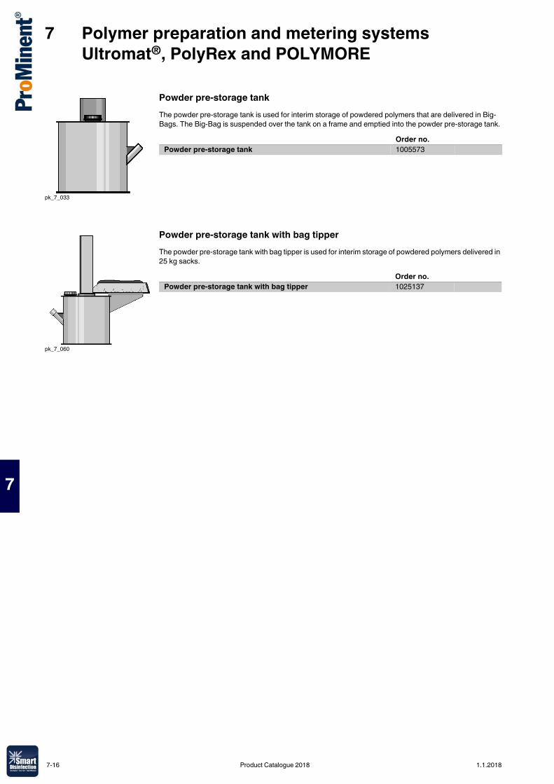
7 Polymer preparation and metering systems Ultromat®, PolyRex and POLYMORE
7
Powder pre-storage tankThe powder pre-storage tank is used for interim storage of powdered polymers that are delivered in Big-Bags. The Big-Bag is suspended over the tank on a frame and emptied into the powder pre-storage tank.
Powder pre-storage tank with bag tipperThe powder pre-storage tank with bag tipper is used for interim storage of powdered polymers delivered in 25 kg sacks.
pk_7_033
Order no.Powder pre-storage tank 1005573
pk_7_060
Order no.Powder pre-storage tank with bag tipper 1025137
7-16 Product Catalogue 2018 1.1.2018
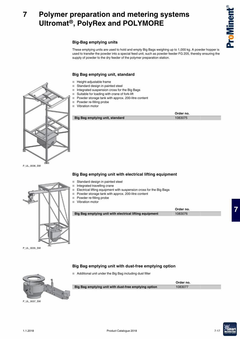
7 Polymer preparation and metering systems Ultromat®, PolyRex and POLYMORE
7
Big-Bag emptying unitsThese emptying units are used to hold and empty Big Bags weighing up to 1,000 kg. A powder hopper is used to transfer the powder into a special feed unit, such as powder feeder FG 205, thereby ensuring the supply of powder to the dry feeder of the polymer preparation station.
Big Bag emptying unit, standard� Height-adjustable frame� Standard design in painted steel� Integrated suspension cross for the Big Bags� Suitable for loading with crane of fork-lift� Powder storage tank with approx. 200-litre content� Powder re-filling probe� Vibration motor
Big Bag emptying unit with electrical lifting equipment� Standard design in painted steel� Integrated travelling crane� Electrical lifting equipment with suspension cross for the Big Bags� Powder storage tank with approx. 200-litre content� Powder re-filling probe� Vibration motor
Big Bag emptying unit with dust-free emptying option� Additional unit under the Big Bag including dust filter
P_UL_0036_SW
Order no.Big Bag emptying unit, standard 1083075
P_UL_0035_SW
Order no.Big Bag emptying unit with electrical lifting equipment 1083076
P_UL_0037_SW
Order no.Big Bag emptying unit with dust-free emptying option 1083077
1.1.2018 Product Catalogue 2018 7-17
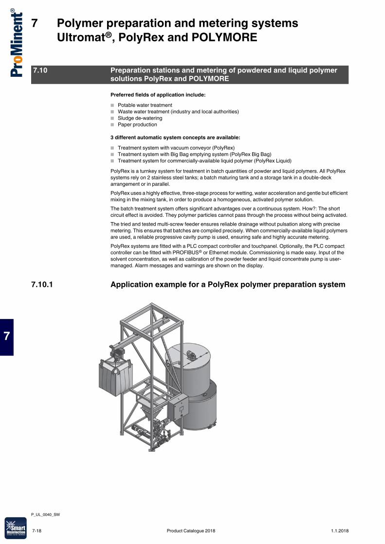
7 Polymer preparation and metering systems Ultromat®, PolyRex and POLYMORE
7
Preferred fields of application include:� Potable water treatment� Waste water treatment (industry and local authorities)� Sludge de-watering� Paper production
3 different automatic system concepts are available:� Treatment system with vacuum conveyor (PolyRex)� Treatment system with Big Bag emptying system (PolyRex Big Bag)� Treatment system for commercially-available liquid polymer (PolyRex Liquid)PolyRex is a turnkey system for treatment in batch quantities of powder and liquid polymers. All PolyRex systems rely on 2 stainless steel tanks; a batch maturing tank and a storage tank in a double-deck arrangement or in parallel.PolyRex uses a highly effective, three-stage process for wetting, water acceleration and gentle but efficient mixing in the mixing tank, in order to produce a homogeneous, activated polymer solution.The batch treatment system offers significant advantages over a continuous system. How?: The short circuit effect is avoided. They polymer particles cannot pass through the process without being activated.The tried and tested multi-screw feeder ensures reliable drainage without pulsation along with precise metering. This ensures that batches are compiled precisely. When commercially-available liquid polymers are used, a reliable progressive cavity pump is used, ensuring safe and highly accurate metering.PolyRex systems are fitted with a PLC compact controller and touchpanel. Optionally, the PLC compact controller can be fitted with PROFIBUS® or Ethernet module. Commissioning is made easy. Input of the solvent concentration, as well as calibration of the powder feeder and liquid concentrate pump is user-managed. Alarm messages and warnings are shown on the display.
7.10.1 Application example for a PolyRex polymer preparation system
7.10 Preparation stations and metering of powdered and liquid polymer solutions PolyRex and POLYMORE
P_UL_0040_SW
7-18 Product Catalogue 2018 1.1.2018
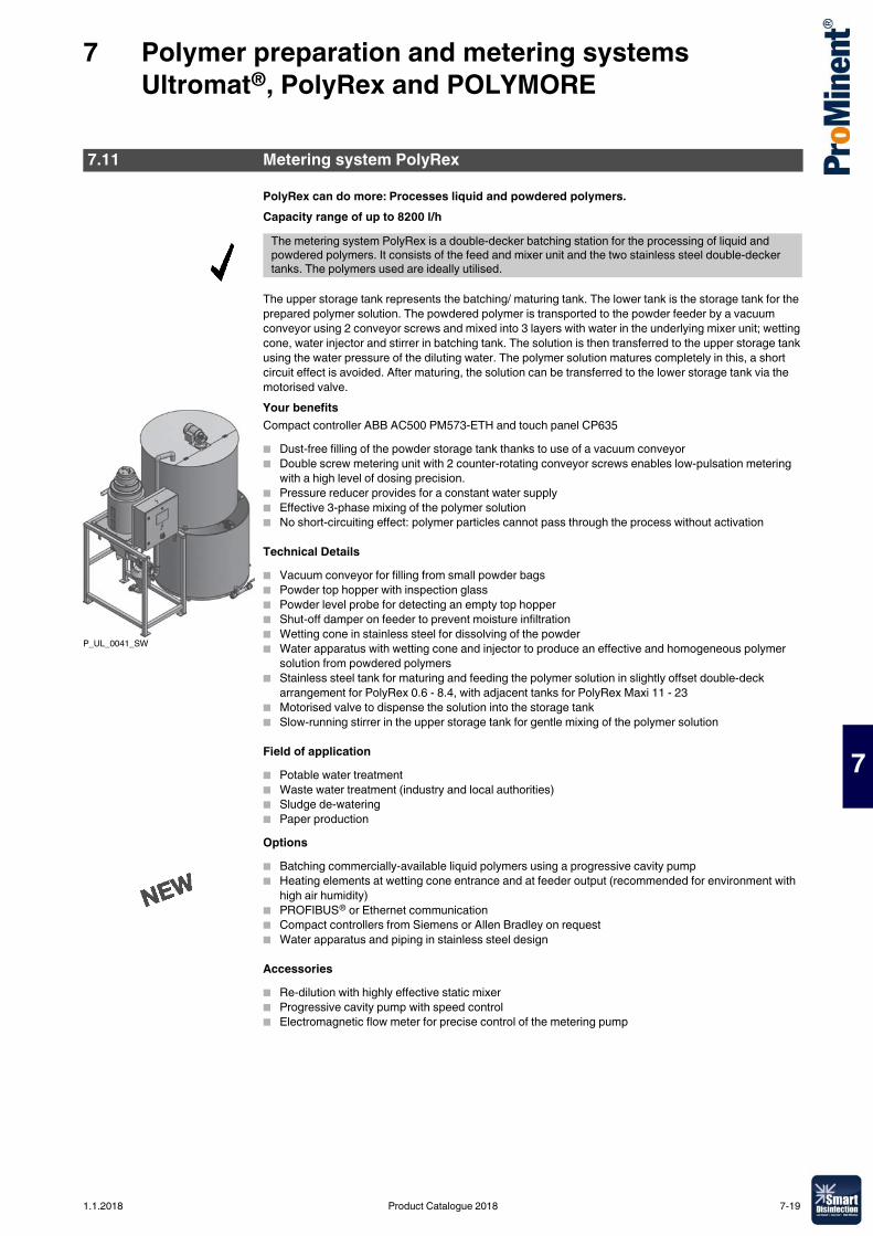
7 Polymer preparation and metering systems Ultromat®, PolyRex and POLYMORE
7
PolyRex can do more: Processes liquid and powdered polymers.Capacity range of up to 8200 l/h
The upper storage tank represents the batching/ maturing tank. The lower tank is the storage tank for the prepared polymer solution. The powdered polymer is transported to the powder feeder by a vacuum conveyor using 2 conveyor screws and mixed into 3 layers with water in the underlying mixer unit; wetting cone, water injector and stirrer in batching tank. The solution is then transferred to the upper storage tank using the water pressure of the diluting water. The polymer solution matures completely in this, a short circuit effect is avoided. After maturing, the solution can be transferred to the lower storage tank via the motorised valve.Your benefitsCompact controller ABB AC500 PM573-ETH and touch panel CP635� Dust-free filling of the powder storage tank thanks to use of a vacuum conveyor� Double screw metering unit with 2 counter-rotating conveyor screws enables low-pulsation metering
with a high level of dosing precision.� Pressure reducer provides for a constant water supply� Effective 3-phase mixing of the polymer solution� No short-circuiting effect: polymer particles cannot pass through the process without activation
Technical Details� Vacuum conveyor for filling from small powder bags� Powder top hopper with inspection glass� Powder level probe for detecting an empty top hopper� Shut-off damper on feeder to prevent moisture infiltration� Wetting cone in stainless steel for dissolving of the powder� Water apparatus with wetting cone and injector to produce an effective and homogeneous polymer
solution from powdered polymers� Stainless steel tank for maturing and feeding the polymer solution in slightly offset double-deck
arrangement for PolyRex 0.6 - 8.4, with adjacent tanks for PolyRex Maxi 11 - 23� Motorised valve to dispense the solution into the storage tank� Slow-running stirrer in the upper storage tank for gentle mixing of the polymer solution
Field of application� Potable water treatment� Waste water treatment (industry and local authorities)� Sludge de-watering� Paper productionOptions� Batching commercially-available liquid polymers using a progressive cavity pump� Heating elements at wetting cone entrance and at feeder output (recommended for environment with
high air humidity)� PROFIBUS® or Ethernet communication� Compact controllers from Siemens or Allen Bradley on request� Water apparatus and piping in stainless steel design
Accessories� Re-dilution with highly effective static mixer� Progressive cavity pump with speed control� Electromagnetic flow meter for precise control of the metering pump
7.11 Metering system PolyRex
The metering system PolyRex is a double-decker batching station for the processing of liquid and powdered polymers. It consists of the feed and mixer unit and the two stainless steel double-decker tanks. The polymers used are ideally utilised.
P_UL_0041_SW
1.1.2018 Product Catalogue 2018 7-19

7 Polymer preparation and metering systems Ultromat®, PolyRex and POLYMORE
7
Tank volume Discharge volume Polymer dosingcapacity
m3 l/h kg/hPolyRex 0.6 2 x 0.3 240 1.2PolyRex 1.0 2 x 0.6 460 2.3PolyRex 2.0 2 x 1.0 940 4.7PolyRex 3.0 2 x 1.5 1,280 6.4PolyRex 4.0 2 x 2.0 1,900 9.5PolyRex 5.4 2 x 2.7 2,400 12.0PolyRex 6.6 2 x 3.3 3,200 16.0PolyRex 8.4 2 x 4.2 3,820 19.2PolyRex Maxi 11 2 x 5.5 5,100 25.5PolyRex Maxi 16 2 x 8.0 6,600 33.0PolyRex Maxi 23 2 x 11.5 8,200 41.0
7-20 Product Catalogue 2018 1.1.2018
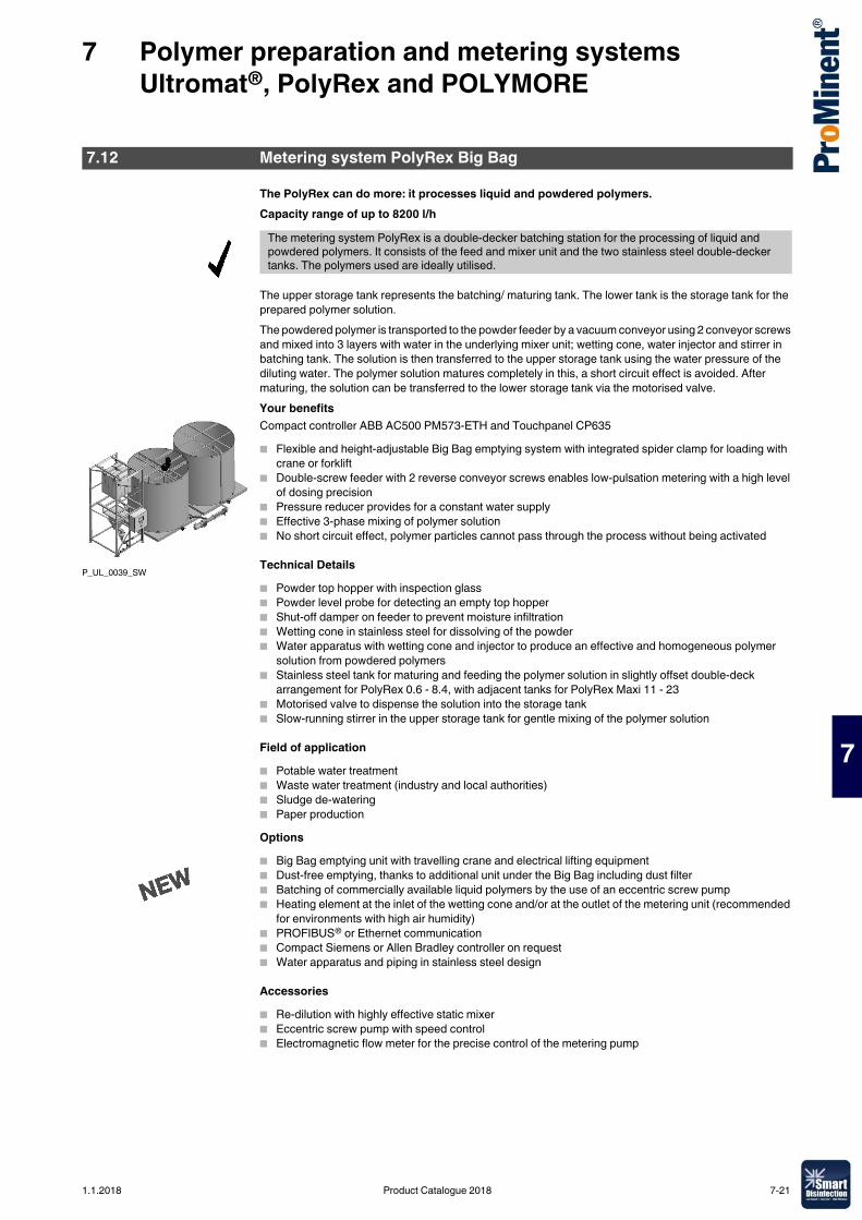
7 Polymer preparation and metering systems Ultromat®, PolyRex and POLYMORE
7
The PolyRex can do more: it processes liquid and powdered polymers.Capacity range of up to 8200 l/h
The upper storage tank represents the batching/ maturing tank. The lower tank is the storage tank for the prepared polymer solution.The powdered polymer is transported to the powder feeder by a vacuum conveyor using 2 conveyor screws and mixed into 3 layers with water in the underlying mixer unit; wetting cone, water injector and stirrer in batching tank. The solution is then transferred to the upper storage tank using the water pressure of the diluting water. The polymer solution matures completely in this, a short circuit effect is avoided. After maturing, the solution can be transferred to the lower storage tank via the motorised valve.Your benefitsCompact controller ABB AC500 PM573-ETH and Touchpanel CP635� Flexible and height-adjustable Big Bag emptying system with integrated spider clamp for loading with
crane or forklift� Double-screw feeder with 2 reverse conveyor screws enables low-pulsation metering with a high level
of dosing precision� Pressure reducer provides for a constant water supply� Effective 3-phase mixing of polymer solution� No short circuit effect, polymer particles cannot pass through the process without being activated
Technical Details� Powder top hopper with inspection glass� Powder level probe for detecting an empty top hopper� Shut-off damper on feeder to prevent moisture infiltration� Wetting cone in stainless steel for dissolving of the powder� Water apparatus with wetting cone and injector to produce an effective and homogeneous polymer
solution from powdered polymers� Stainless steel tank for maturing and feeding the polymer solution in slightly offset double-deck
arrangement for PolyRex 0.6 - 8.4, with adjacent tanks for PolyRex Maxi 11 - 23� Motorised valve to dispense the solution into the storage tank� Slow-running stirrer in the upper storage tank for gentle mixing of the polymer solution
Field of application� Potable water treatment� Waste water treatment (industry and local authorities)� Sludge de-watering� Paper productionOptions� Big Bag emptying unit with travelling crane and electrical lifting equipment� Dust-free emptying, thanks to additional unit under the Big Bag including dust filter� Batching of commercially available liquid polymers by the use of an eccentric screw pump� Heating element at the inlet of the wetting cone and/or at the outlet of the metering unit (recommended
for environments with high air humidity)� PROFIBUS® or Ethernet communication� Compact Siemens or Allen Bradley controller on request� Water apparatus and piping in stainless steel design
Accessories� Re-dilution with highly effective static mixer� Eccentric screw pump with speed control� Electromagnetic flow meter for the precise control of the metering pump
7.12 Metering system PolyRex Big Bag
The metering system PolyRex is a double-decker batching station for the processing of liquid and powdered polymers. It consists of the feed and mixer unit and the two stainless steel double-decker tanks. The polymers used are ideally utilised.
P_UL_0039_SW
1.1.2018 Product Catalogue 2018 7-21
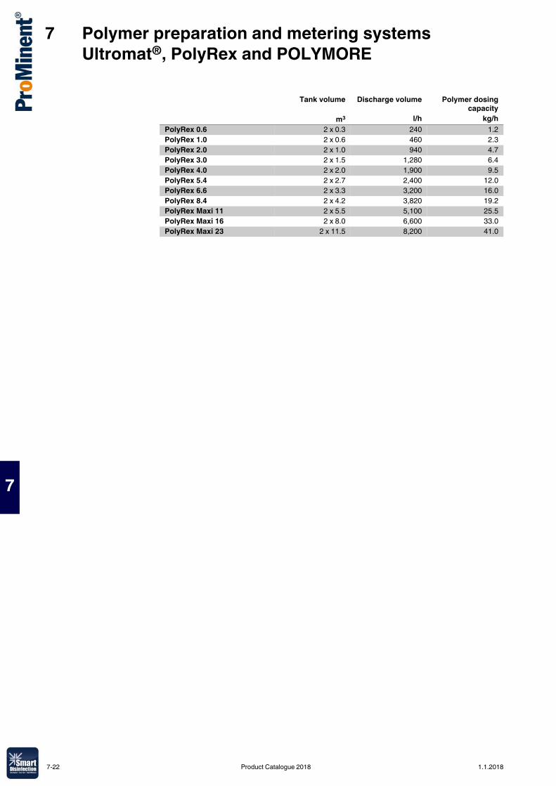
7 Polymer preparation and metering systems Ultromat®, PolyRex and POLYMORE
7
Tank volume Discharge volume Polymer dosingcapacity
m3 l/h kg/hPolyRex 0.6 2 x 0.3 240 1.2PolyRex 1.0 2 x 0.6 460 2.3PolyRex 2.0 2 x 1.0 940 4.7PolyRex 3.0 2 x 1.5 1,280 6.4PolyRex 4.0 2 x 2.0 1,900 9.5PolyRex 5.4 2 x 2.7 2,400 12.0PolyRex 6.6 2 x 3.3 3,200 16.0PolyRex 8.4 2 x 4.2 3,820 19.2PolyRex Maxi 11 2 x 5.5 5,100 25.5PolyRex Maxi 16 2 x 8.0 6,600 33.0PolyRex Maxi 23 2 x 11.5 8,200 41.0
7-22 Product Catalogue 2018 1.1.2018
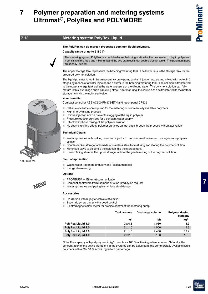
7 Polymer preparation and metering systems Ultromat®, PolyRex and POLYMORE
7
The PolyRex can do more: it processes common liquid polymers.Capacity range of up to 3180 l/h
The upper storage tank represents the batching/maturing tank. The lower tank is the storage tank for the prepared polymer solution.The liquid polymer is fed in by an eccentric screw pump and an injection nozzle and mixed with water in 2 stages by means of a water injector and a stirrer in the batching/maturing tank. The solution is transferred to the upper storage tank using the water pressure of the diluting water. The polymer solution can fully mature in this, avoiding a short-circuiting effect. After maturing, the solution can be transferred to the bottom storage tank via the motorised valve.Your benefitsCompact controller ABB AC500 PM573-ETH and touch panel CP635� Reliable eccentric screw pump for the metering of commercially available polymers� High energy mixing process� Unique injection nozzle prevents clogging of the liquid polymer� Pressure reducer provides for a constant water supply� Effective 2-phase mixing of the polymer solution� No short-circuiting effect: polymer particles cannot pass through the process without activation
Technical Details� Water apparatus with wetting cone and injector to produce an effective and homogeneous polymer
solution� Double-decker storage tank made of stainless steel for maturing and storing the polymer solution� Motorised valve to dispense the solution into the storage tank� Slow-rotating stirrer in the upper storage tank for the gentle mixing of the polymer solution
Field of application� Waste water treatment (industry and local authorities)� Sludge de-wateringOptions� PROFIBUS® or Ethernet communication� Compact controllers from Siemens or Allen Bradley on request� Water apparatus and piping in stainless steel design
Accessories� Re-dilution with highly effective static mixer� Eccentric screw pump with speed control� Electromagnetic flow meter for precise control of the metering pump
Note:The capacity of liquid polymer in kg/h denotes a 100 % active ingredient content. Naturally, the concentration of the active ingredient in the systems can be adjusted to the commercially available liquid polymers with a 30 - 60 % active ingredient percentage.
7.13 Metering system PolyRex Liquid
The metering system PolyRex is a double-decker batching station for the processing of liquid polymers. It consists of the feed and mixer unit and the two stainless steel double-decker tanks. The polymers used are ideally utilised.
P_UL_0038_SW
Tank volume Discharge volume Polymer dosingcapacity
m3 l/h kg/hPolyRex Liquid 1.0 2 x 0.5 1,060 5.3PolyRex Liquid 2.0 2 x 1.0 1,900 9.5PolyRex Liquid 3.0 2 x 1.5 2,480 12.4PolyRex Liquid 4.0 2 x 2.0 3,180 15.9
1.1.2018 Product Catalogue 2018 7-23
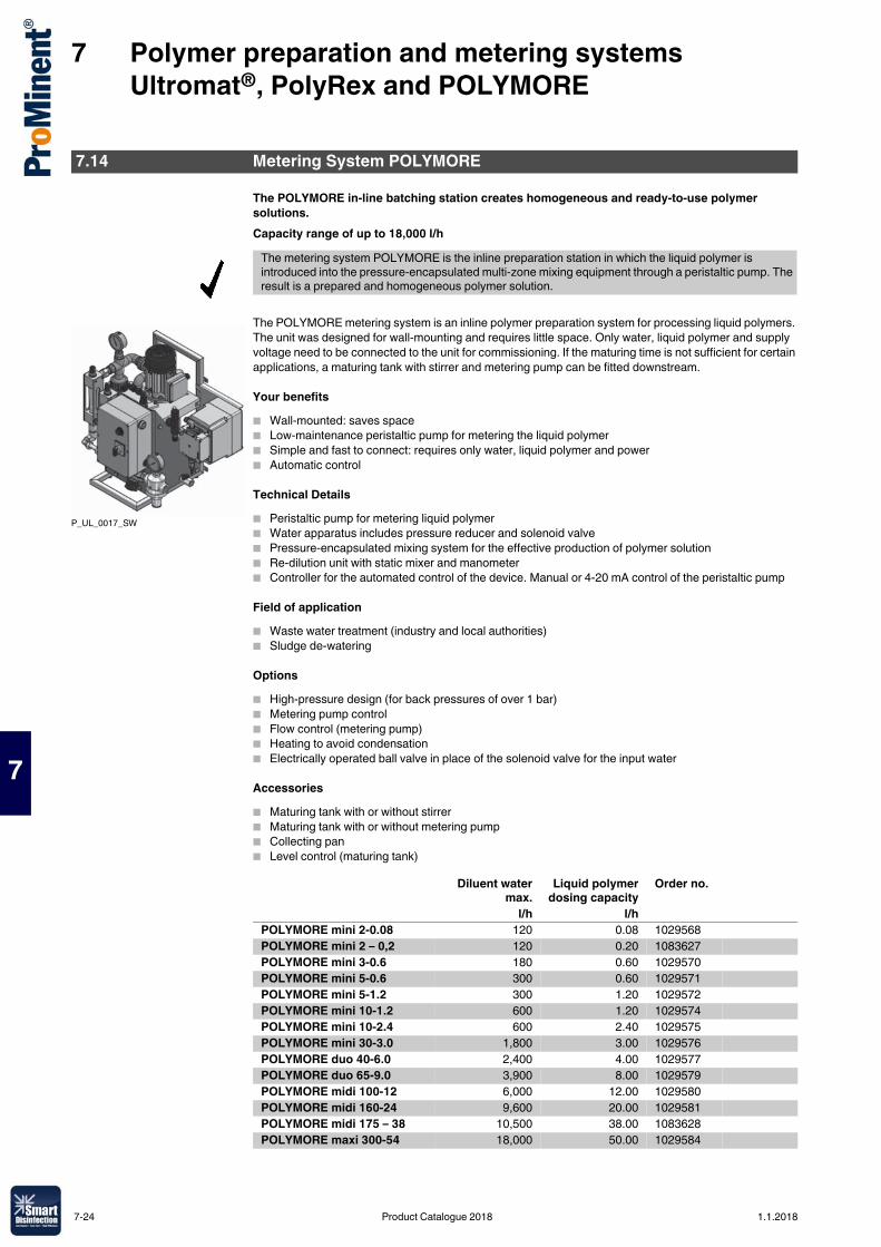
7 Polymer preparation and metering systems Ultromat®, PolyRex and POLYMORE
7
The POLYMORE in-line batching station creates homogeneous and ready-to-use polymer solutions.Capacity range of up to 18,000 l/h
The POLYMORE metering system is an inline polymer preparation system for processing liquid polymers. The unit was designed for wall-mounting and requires little space. Only water, liquid polymer and supply voltage need to be connected to the unit for commissioning. If the maturing time is not sufficient for certain applications, a maturing tank with stirrer and metering pump can be fitted downstream.
Your benefits� Wall-mounted: saves space� Low-maintenance peristaltic pump for metering the liquid polymer� Simple and fast to connect: requires only water, liquid polymer and power� Automatic control
Technical Details� Peristaltic pump for metering liquid polymer� Water apparatus includes pressure reducer and solenoid valve� Pressure-encapsulated mixing system for the effective production of polymer solution� Re-dilution unit with static mixer and manometer� Controller for the automated control of the device. Manual or 4-20 mA control of the peristaltic pump
Field of application� Waste water treatment (industry and local authorities)� Sludge de-watering
Options� High-pressure design (for back pressures of over 1 bar)� Metering pump control� Flow control (metering pump)� Heating to avoid condensation� Electrically operated ball valve in place of the solenoid valve for the input water
Accessories� Maturing tank with or without stirrer� Maturing tank with or without metering pump� Collecting pan� Level control (maturing tank)
7.14 Metering System POLYMORE
The metering system POLYMORE is the inline preparation station in which the liquid polymer is introduced into the pressure-encapsulated multi-zone mixing equipment through a peristaltic pump. The result is a prepared and homogeneous polymer solution.
P_UL_0017_SW
Diluent watermax.
Liquid polymerdosing capacity
Order no.
l/h l/hPOLYMORE mini 2-0.08 120 0.08 1029568POLYMORE mini 2 – 0,2 120 0.20 1083627POLYMORE mini 3-0.6 180 0.60 1029570POLYMORE mini 5-0.6 300 0.60 1029571POLYMORE mini 5-1.2 300 1.20 1029572POLYMORE mini 10-1.2 600 1.20 1029574POLYMORE mini 10-2.4 600 2.40 1029575POLYMORE mini 30-3.0 1,800 3.00 1029576POLYMORE duo 40-6.0 2,400 4.00 1029577POLYMORE duo 65-9.0 3,900 8.00 1029579POLYMORE midi 100-12 6,000 12.00 1029580POLYMORE midi 160-24 9,600 20.00 1029581POLYMORE midi 175 – 38 10,500 38.00 1083628POLYMORE maxi 300-54 18,000 50.00 1029584
7-24 Product Catalogue 2018 1.1.2018
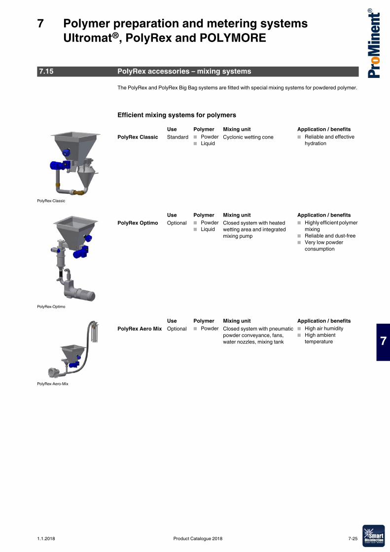
7 Polymer preparation and metering systems Ultromat®, PolyRex and POLYMORE
7
The PolyRex and PolyRex Big Bag systems are fitted with special mixing systems for powdered polymer.
Efficient mixing systems for polymers
7.15 PolyRex accessories – mixing systems
PolyRex-Classic
Use Polymer Mixing unit Application / benefitsPolyRex Classic Standard � Powder
� LiquidCyclonic wetting cone � Reliable and effective
hydration
PolyRex-Optimo
Use Polymer Mixing unit Application / benefitsPolyRex Optimo Optional � Powder
� LiquidClosed system with heated wetting area and integrated mixing pump
� Highly efficient polymer mixing
� Reliable and dust-free� Very low powder
consumption
PolyRex-Aero-Mix
Use Polymer Mixing unit Application / benefitsPolyRex Aero Mix Optional � Powder Closed system with pneumatic
powder conveyance, fans, water nozzles, mixing tank
� High air humidity� High ambient
temperature
1.1.2018 Product Catalogue 2018 7-25

7-26 Product Catalogue 2018 1.1.2018
8 Membrane Technology and Membrane Filtration
8
8.0.1Product Catalogue 2018
Systems for membrane filtrationIn water treatment, membrane filtration is the process for removing particles and salts in the water ensuring the lowest operating costs. ProMinent offers versatile and high-quality system technology in this field. This is complemented by the extensive ProMinent product range to produce customer-specific complete solutions.Membrane filtration is a physical process to separate substances with the help of semi-permeable membranes. There are four types of processes, depending on the size of the particles/molecules to be removed:� Microfiltration� Ultrafiltration� Nanofiltration� Reverse osmosisThe following table shows the separation limits of the individual processes:
ProMinent experts, with their detailed industry knowledge, are not only able to put together the optimum system for the relevant application but also deliver complete water treatment solutions from one source, supported by the extensive ProMinent product range.
8.1 Overview of Membrane Technology
Microfiltration Ultrafiltration Nanofiltration Reverse osmosisParticle size > 0.1 μm 0.1 – 0.01 μm 0.01 – 0.001 μm < 0.001 μmParticle type Suspended
particles, colloidal turbidity, oil emulsions
Macromolecules, bacteria, cells, viruses, proteins
Low-molecular organic compounds, ions
Ions
1.1.2018 Product Catalogue 2018 8-1
8 Membrane Technology and Membrane Filtration
8
Ultrafiltration is a membrane process which is increasingly used in water treatment to separate undesired water components. Parasites, bacteria, viruses and high-molecular organic substances as well as other particles are retained.The applications of ultrafiltration are widespread and may include different types of water.Typical applications include drinking water, river water, process water, swimming pool water, salt water and waste water.The tasks range from potable water purification to meet physical and microbiological limit values in accordance with the German Drinking Water Ordinance up to the pre-treatment of seawater for desalination by reverse osmosis.The systems are matched to a specific task by individually selecting the membrane type and the operating mode. ProMinent uses extremely robust and resistant UF membranes and the dead-end principle to ensure optimisation with regard to investment costs, required space and operating costs. With this selection, all raw waters with the exception of waste water can be filtered largely without using chemicals.The dead-end operation represents the standard operating mode. The raw water flows into the capillaries. The pure water (filtrate) passes through the membrane while the other constituents are retained on the surface of the membrane.The constituents form a layer on the membrane. The membrane is backwashed fully automatically in regular intervals to remove the filter cake.
Ultrafiltration systems basically consist of:� Stainless steel or high-grade coated steel rack� Pre-filter to protect the membranes, if required. This filter can optionally be designed as a backwashing
filter.� UF membrane modules� Pneumatically controlled valves made of high-quality materials � Electronic pressure measurement� Filtration pump and backwash pump with frequency converter made of suitable high-quality materials � Magnetically inductive flow metering to control the flow rates for filtration and backwashing.� Integrated filling system for the backwash water tank. The backwash water tank is also integral to small
systems. With larger systems, tanks from our product range can be integrated or an application-specific solution found depending on the customer's requirements.
� PLC control with touch screen panel or microprocessor control unit.The PLC control simultaneously monitors all important parameters, such as pressure, pressure difference and flow rates. This ensures that the membranes are optimally protected. The control of pre- and post-treatment processes can be integrated, if required.
Advantages of ultrafiltration systems� Filtrate values of less than 0.1 NTU independent of the turbidity of the raw water.� Molecular weight cut off of the membranes (MWCO) approx. 100 kDa (kilodalton).� Best possible retention rates for bacteria (99.9999%) and viruses (99.99% based on MS2 phages).� Very easy to use and simple to combine with other systems owing to PLC Programmable Logic
Controller with touch screen.� Optimum operating processes due to modern measuring and control technology.� Complete solutions with perfectly coordinated pre- and post-treatment are available on request.
8.2 Performance Overview of Ultrafiltration
8-2 Product Catalogue 2018 1.1.2018
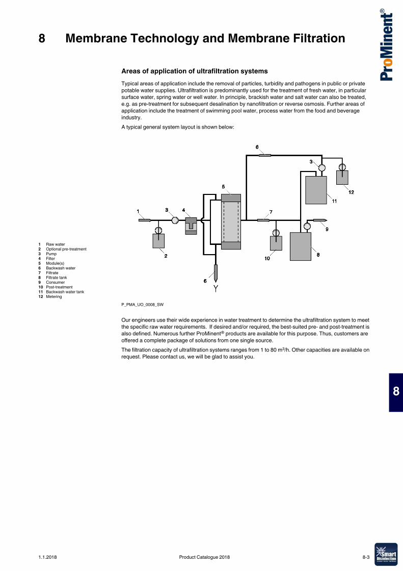
8 Membrane Technology and Membrane Filtration
8
Areas of application of ultrafiltration systemsTypical areas of application include the removal of particles, turbidity and pathogens in public or private potable water supplies. Ultrafiltration is predominantly used for the treatment of fresh water, in particular surface water, spring water or well water. In principle, brackish water and salt water can also be treated, e.g. as pre-treatment for subsequent desalination by nanofiltration or reverse osmosis. Further areas of application include the treatment of swimming pool water, process water from the food and beverage industry. A typical general system layout is shown below:
P_PMA_UO_0008_SW
Our engineers use their wide experience in water treatment to determine the ultrafiltration system to meet the specific raw water requirements. If desired and/or required, the best-suited pre- and post-treatment is also defined. Numerous further ProMinent® products are available for this purpose. Thus, customers are offered a complete package of solutions from one single source.The filtration capacity of ultrafiltration systems ranges from 1 to 80 m3/h. Other capacities are available on request. Please contact us, we will be glad to assist you.
1 Raw water2 Optional pre-treatment3 Pump4 Filter5 Module(s)6 Backwash water7 Filtrate8 Filtrate tank9 Consumer10 Post-treatment11 Backwash water tank12 Metering
1.1.2018 Product Catalogue 2018 8-3
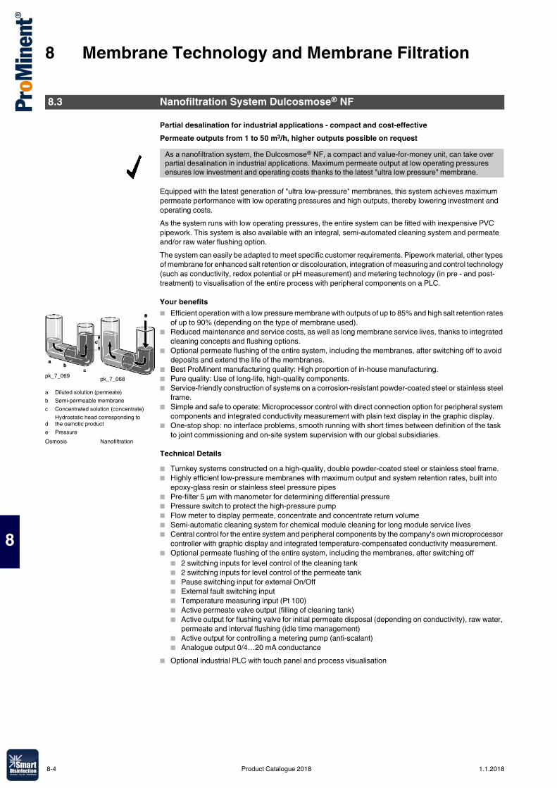
8 Membrane Technology and Membrane Filtration
8
Partial desalination for industrial applications - compact and cost-effectivePermeate outputs from 1 to 50 m3/h, higher outputs possible on request
Equipped with the latest generation of "ultra low-pressure" membranes, this system achieves maximum permeate performance with low operating pressures and high outputs, thereby lowering investment and operating costs.As the system runs with low operating pressures, the entire system can be fitted with inexpensive PVC pipework. This system is also available with an integral, semi-automated cleaning system and permeate and/or raw water flushing option.The system can easily be adapted to meet specific customer requirements. Pipework material, other types of membrane for enhanced salt retention or discolouration, integration of measuring and control technology (such as conductivity, redox potential or pH measurement) and metering technology (in pre - and post-treatment) to visualisation of the entire process with peripheral components on a PLC.
Your benefits� Efficient operation with a low pressure membrane with outputs of up to 85% and high salt retention rates
of up to 90% (depending on the type of membrane used).� Reduced maintenance and service costs, as well as long membrane service lives, thanks to integrated
cleaning concepts and flushing options.� Optional permeate flushing of the entire system, including the membranes, after switching off to avoid
deposits and extend the life of the membranes.� Best ProMinent manufacturing quality: High proportion of in-house manufacturing.� Pure quality: Use of long-life, high-quality components.� Service-friendly construction of systems on a corrosion-resistant powder-coated steel or stainless steel
frame. � Simple and safe to operate: Microprocessor control with direct connection option for peripheral system
components and integrated conductivity measurement with plain text display in the graphic display.� One-stop shop: no interface problems, smooth running with short times between definition of the task
to joint commissioning and on-site system supervision with our global subsidiaries.
Technical Details� Turnkey systems constructed on a high-quality, double powder-coated steel or stainless steel frame.� Highly efficient low-pressure membranes with maximum output and system retention rates, built into
epoxy-glass resin or stainless steel pressure pipes� Pre-filter 5 µm with manometer for determining differential pressure� Pressure switch to protect the high-pressure pump� Flow meter to display permeate, concentrate and concentrate return volume� Semi-automatic cleaning system for chemical module cleaning for long module service lives � Central control for the entire system and peripheral components by the company's own microprocessor
controller with graphic display and integrated temperature-compensated conductivity measurement.� Optional permeate flushing of the entire system, including the membranes, after switching off
� 2 switching inputs for level control of the cleaning tank� 2 switching inputs for level control of the permeate tank� Pause switching input for external On/Off� External fault switching input� Temperature measuring input (Pt 100)� Active permeate valve output (filling of cleaning tank)� Active output for flushing valve for initial permeate disposal (depending on conductivity), raw water,
permeate and interval flushing (idle time management)� Active output for controlling a metering pump (anti-scalant)� Analogue output 0/4…20 mA conductance
� Optional industrial PLC with touch panel and process visualisation
8.3 Nanofiltration System Dulcosmose® NF
As a nanofiltration system, the Dulcosmose® NF, a compact and value-for-money unit, can take over partial desalination in industrial applications. Maximum permeate output at low operating pressures ensures low investment and operating costs thanks to the latest "ultra low pressure" membrane.
pk_7_069 pk_7_068
Osmosis Nanofiltration
a Diluted solution (permeate)b Semi-permeable membranec Concentrated solution (concentrate)
dHydrostatic head corresponding to the osmotic product
e Pressure
8-4 Product Catalogue 2018 1.1.2018
8 Membrane Technology and Membrane Filtration
8
Field of application� Low-cost alternative to reverse osmosis systems for special desalination tasks, such as the elimination
of multiple charged ions or the removal of dyes� Partial water softening or water softening in public drinking water� Partial desalination in the chemical and pharmaceutical industry, food and beverage industry, metal
processing industry and in electroplatingNanofiltration is based on the same principle as reverse osmosis. The difference: The separation limit is slightly lower. Admittedly this type of membrane filtration retains ions dissolved in water, but to a significantly lesser extent than with reverse osmosis. Ultimately that saves operating costs.Typical salt retention rates are around 80 – 90%. Multi-value ions (e. g. Ca and Mg) are retained better than single-value ions (e. g. Na, K) so that nanofiltration systems are often also used as an alternative to traditional water softening.In principle with nanofiltration, the raw water to be softened is introduced into a chamber, separated by a semi-permeable membrane. An artificial pressure is generated in the chamber against the osmotic pressure gradient. The membrane is permeable to pure water and smaller ions. All other components of the water are retained. This produces partially softened water (permeate) and a concentrated solution (concentrate). ProMinent uses high-quality nanofiltration membranes for this process.
1.1.2018 Product Catalogue 2018 8-5
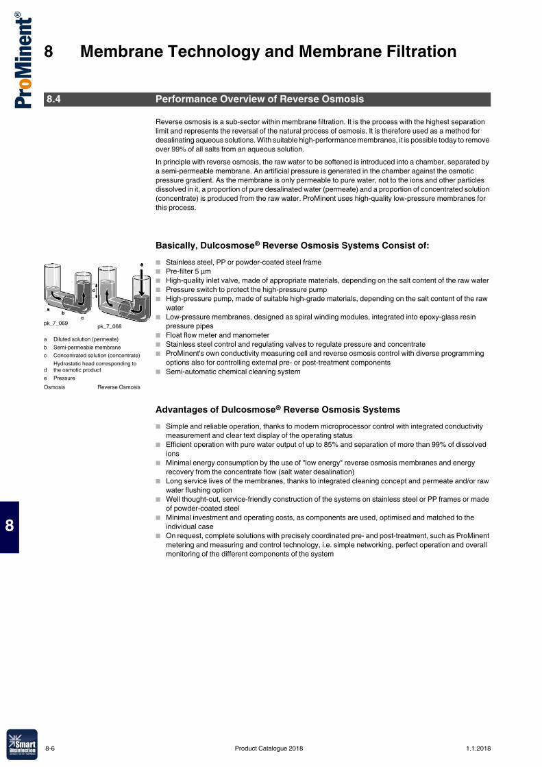
8 Membrane Technology and Membrane Filtration
8
Reverse osmosis is a sub-sector within membrane filtration. It is the process with the highest separation limit and represents the reversal of the natural process of osmosis. It is therefore used as a method for desalinating aqueous solutions. With suitable high-performance membranes, it is possible today to remove over 99% of all salts from an aqueous solution.In principle with reverse osmosis, the raw water to be softened is introduced into a chamber, separated by a semi-permeable membrane. An artificial pressure is generated in the chamber against the osmotic pressure gradient. As the membrane is only permeable to pure water, not to the ions and other particles dissolved in it, a proportion of pure desalinated water (permeate) and a proportion of concentrated solution (concentrate) is produced from the raw water. ProMinent uses high-quality low-pressure membranes for this process.
Basically, Dulcosmose® Reverse Osmosis Systems Consist of:� Stainless steel, PP or powder-coated steel frame� Pre-filter 5 µm� High-quality inlet valve, made of appropriate materials, depending on the salt content of the raw water� Pressure switch to protect the high-pressure pump� High-pressure pump, made of suitable high-grade materials, depending on the salt content of the raw
water� Low-pressure membranes, designed as spiral winding modules, integrated into epoxy-glass resin
pressure pipes� Float flow meter and manometer� Stainless steel control and regulating valves to regulate pressure and concentrate� ProMinent's own conductivity measuring cell and reverse osmosis control with diverse programming
options also for controlling external pre- or post-treatment components� Semi-automatic chemical cleaning system
Advantages of Dulcosmose® Reverse Osmosis Systems� Simple and reliable operation, thanks to modern microprocessor control with integrated conductivity
measurement and clear text display of the operating status � Efficient operation with pure water output of up to 85% and separation of more than 99% of dissolved
ions� Minimal energy consumption by the use of "low energy" reverse osmosis membranes and energy
recovery from the concentrate flow (salt water desalination)� Long service lives of the membranes, thanks to integrated cleaning concept and permeate and/or raw
water flushing option� Well thought-out, service-friendly construction of the systems on stainless steel or PP frames or made
of powder-coated steel� Minimal investment and operating costs, as components are used, optimised and matched to the
individual case� On request, complete solutions with precisely coordinated pre- and post-treatment, such as ProMinent
metering and measuring and control technology, i.e. simple networking, perfect operation and overall monitoring of the different components of the system
8.4 Performance Overview of Reverse Osmosis
pk_7_069 pk_7_068
Osmosis Reverse Osmosis
a Diluted solution (permeate)b Semi-permeable membranec Concentrated solution (concentrate)
dHydrostatic head corresponding to the osmotic product
e Pressure
8-6 Product Catalogue 2018 1.1.2018
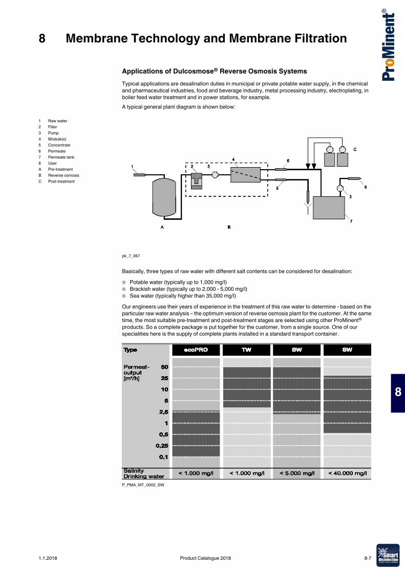
8 Membrane Technology and Membrane Filtration
8
Applications of Dulcosmose® Reverse Osmosis SystemsTypical applications are desalination duties in municipal or private potable water supply, in the chemical and pharmaceutical industries, food and beverage industry, metal processing industry, electroplating, in boiler feed water treatment and in power stations, for example.A typical general plant diagram is shown below:
pk_7_067
Basically, three types of raw water with different salt contents can be considered for desalination:� Potable water (typically up to 1,000 mg/l)� Brackish water (typically up to 2,000 - 5,000 mg/l)� Sea water (typically higher than 35,000 mg/l)Our engineers use their years of experience in the treatment of this raw water to determine - based on the particular raw water analysis – the optimum version of reverse osmosis plant for the customer. At the same time, the most suitable pre-treatment and post-treatment stages are selected using other ProMinent® products. So a complete package is put together for the customer, from a single source. One of our specialities here is the supply of complete plants installed in a standard transport container.
P_PMA_MT_0002_SW
1 Raw water2 Filter3 Pump4 Module(s)5 Concentrate6 Permeate7 Permeate tank8 UserA Pre-treatmentB Reverse osmosisC Post-treatment
1.1.2018 Product Catalogue 2018 8-7
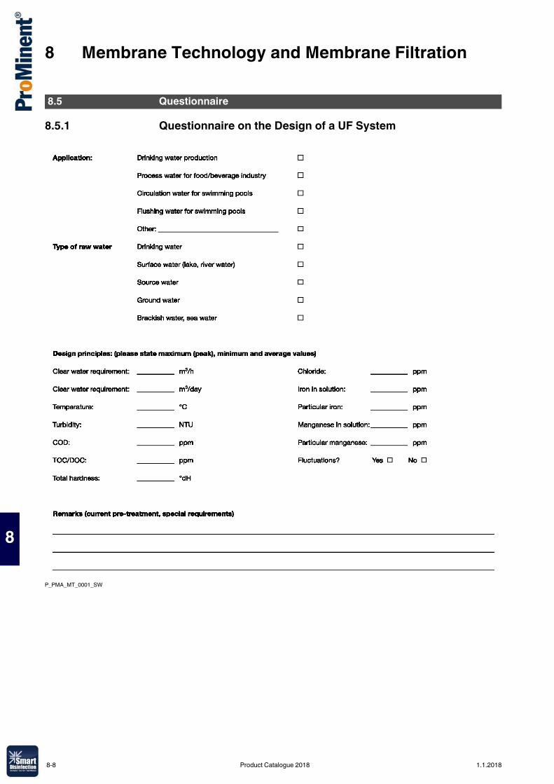
8 Membrane Technology and Membrane Filtration
8
8.5.1 Questionnaire on the Design of a UF System
P_PMA_MT_0001_SW
8.5 Questionnaire
8-8 Product Catalogue 2018 1.1.2018
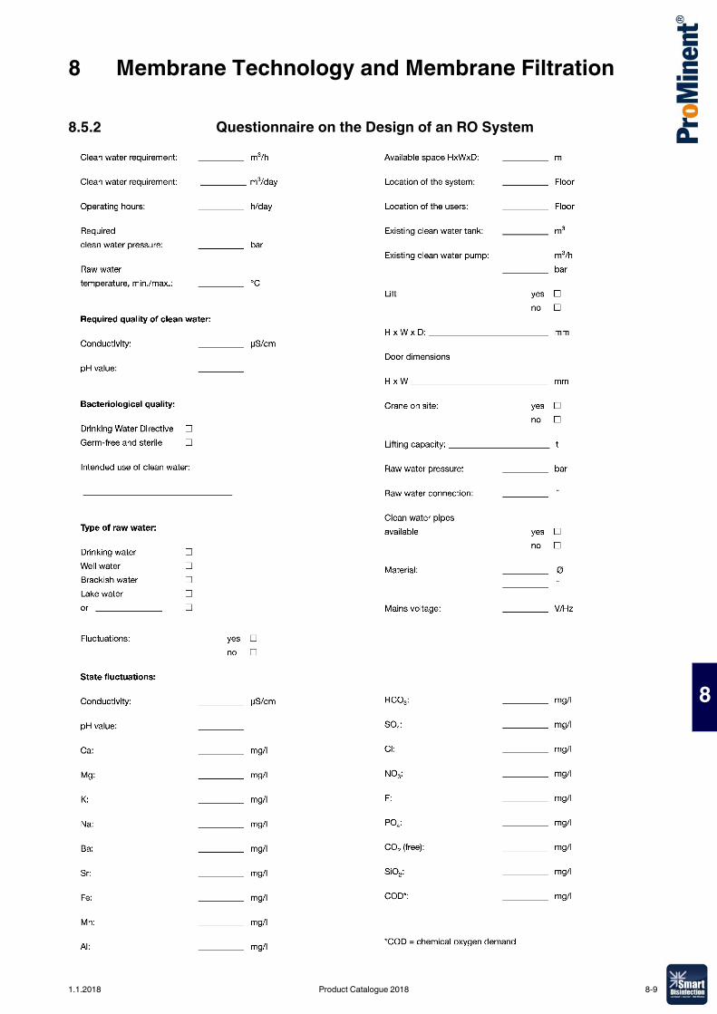
8 Membrane Technology and Membrane Filtration
8
8.5.2 Questionnaire on the Design of an RO System
1.1.2018 Product Catalogue 2018 8-9
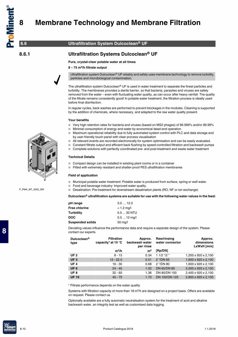
8 Membrane Technology and Membrane Filtration
8
8.6.1 Ultrafiltration Systems Dulcoclean® UFPure, crystal-clear potable water at all times8 – 75 m3/h filtrate output
The ultrafiltration system Dulcoclean® UF is used in water treatment to separate the finest particles and turbidity. The membranes provides a sterile barrier, so that bacteria, parasites and viruses are safely removed from the water – even with fluctuating water quality, as can occur after heavy rainfall. The quality of the filtrate remains consistently good! In potable water treatment, the filtration process is ideally used before final disinfection.In regular cycles, back washes are performed to prevent blockages in the modules. Cleaning is supported by the addition of chemicals, where necessary, and adapted to the raw water quality present.
Your benefits� Very high retention rates for bacteria and viruses (based on MS2 phages) of 99.999% and/or 99.99%� Minimal consumption of energy and water by economical dead-end operation� Maximum operational reliability due to fully automated system control with PLC and data storage and
by user-friendly touch panel with clear process visualisation� All relevant events are recorded electronically for system optimisation and can be easily evaluated.� Constant filtrate output and efficient back flushing by speed-controlled filtration and backwash pumps� Complete solutions with perfectly coordinated pre- and post-treatment and waste water treatment
Technical Details� Compact design can be installed in existing plant rooms or in a container� Fitted with extremely resistant and shatter-proof PES ultrafiltration membranes
Field of application� Municipal potable water treatment: Potable water is produced from surface, spring or well water.� Food and beverage industry: Improved water quality.� Desalination: Pre-treatment for downstream desalination plants (RO, NF or ion exchange)Dulcoclean® ultrafiltration systems are suitable for use with the following water values in the feed:
Deviating values influence the performance data and require a separate design of the system. Please contact our experts.
* Filtrate performance depends on the water qualitySystems with filtration capacity of more than 18 m3/h are designed on a project basis. Offers are available on request. Please contact us.Optionally available are a fully automatic neutralisation system for the treatment of acid and alkaline backwash water, an integrity test as well as customised data logging.
8.6 Ultrafiltration System Dulcoclean® UF
Ultrafiltration system Dulcoclean® UF reliably and safely uses membrane technology to remove turbidity, particles and microbiological contamination.
P_PMA_MT_0003_SW
pH range 3.0 … 12.0Free chlorine < 1.2 mg/lTurbidity 0.5 ... 30 NTUDOC 0.5 ... 12 mg/lSuspended solids 50 mg/l
Dulcoclean® type
Filtrationcapacity* at 15 °C
Approx.backwash water
per rinse
Raw/rinsing water connector
Approx.dimensions
LxWxH [mm]m3/h m3 [Rp/DN]
UF 2 8 - 15 0.34 1 1/2 "/2 " 1,200 x 920 x 2,100UF 3 12 - 22.5 0.51 2 "/DN 65 1,600 x 920 x 2,100UF 4 16 - 30 0.68 2 "/DN 80 1,600 x 920 x 2,100UF 6 24 - 45 1.02 DN 65/DN 80 2,000 x 920 x 2,100UF 8 32 - 60 1.36 DN 80/DN 100 2,400 x 920 x 2,100UF 10 40 - 75 1.70 DN 100/DN 125 2,800 x 920 x 2,100
8-10 Product Catalogue 2018 1.1.2018
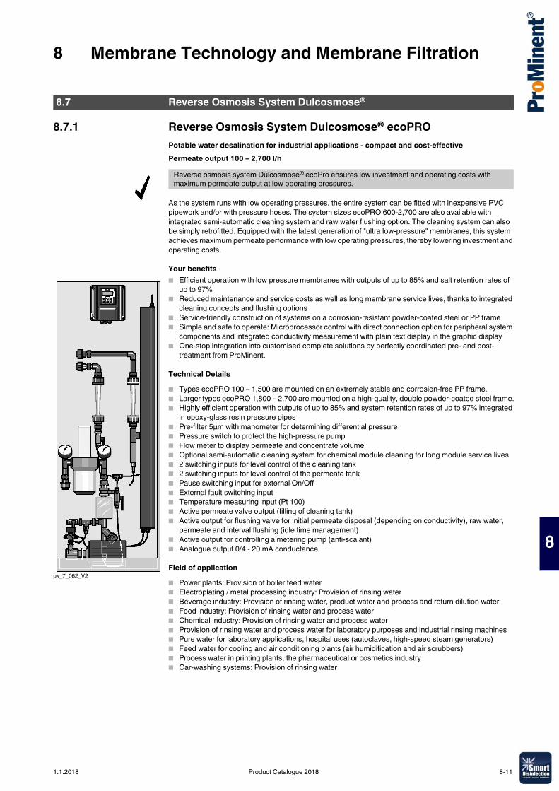
8 Membrane Technology and Membrane Filtration
8
8.7.1 Reverse Osmosis System Dulcosmose® ecoPROPotable water desalination for industrial applications - compact and cost-effectivePermeate output 100 – 2,700 l/h
As the system runs with low operating pressures, the entire system can be fitted with inexpensive PVC pipework and/or with pressure hoses. The system sizes ecoPRO 600-2,700 are also available with integrated semi-automatic cleaning system and raw water flushing option. The cleaning system can also be simply retrofitted. Equipped with the latest generation of "ultra low-pressure" membranes, this system achieves maximum permeate performance with low operating pressures, thereby lowering investment and operating costs.
Your benefits� Efficient operation with low pressure membranes with outputs of up to 85% and salt retention rates of
up to 97%� Reduced maintenance and service costs as well as long membrane service lives, thanks to integrated
cleaning concepts and flushing options� Service-friendly construction of systems on a corrosion-resistant powder-coated steel or PP frame� Simple and safe to operate: Microprocessor control with direct connection option for peripheral system
components and integrated conductivity measurement with plain text display in the graphic display� One-stop integration into customised complete solutions by perfectly coordinated pre- and post-
treatment from ProMinent.
Technical Details� Types ecoPRO 100 – 1,500 are mounted on an extremely stable and corrosion-free PP frame.� Larger types ecoPRO 1,800 – 2,700 are mounted on a high-quality, double powder-coated steel frame.� Highly efficient operation with outputs of up to 85% and system retention rates of up to 97% integrated
in epoxy-glass resin pressure pipes� Pre-filter 5µm with manometer for determining differential pressure� Pressure switch to protect the high-pressure pump� Flow meter to display permeate and concentrate volume� Optional semi-automatic cleaning system for chemical module cleaning for long module service lives � 2 switching inputs for level control of the cleaning tank� 2 switching inputs for level control of the permeate tank� Pause switching input for external On/Off� External fault switching input� Temperature measuring input (Pt 100)� Active permeate valve output (filling of cleaning tank)� Active output for flushing valve for initial permeate disposal (depending on conductivity), raw water,
permeate and interval flushing (idle time management)� Active output for controlling a metering pump (anti-scalant)� Analogue output 0/4 - 20 mA conductance
Field of application� Power plants: Provision of boiler feed water� Electroplating / metal processing industry: Provision of rinsing water� Beverage industry: Provision of rinsing water, product water and process and return dilution water� Food industry: Provision of rinsing water and process water� Chemical industry: Provision of rinsing water and process water� Provision of rinsing water and process water for laboratory purposes and industrial rinsing machines� Pure water for laboratory applications, hospital uses (autoclaves, high-speed steam generators)� Feed water for cooling and air conditioning plants (air humidification and air scrubbers)� Process water in printing plants, the pharmaceutical or cosmetics industry� Car-washing systems: Provision of rinsing water
8.7 Reverse Osmosis System Dulcosmose®
Reverse osmosis system Dulcosmose® ecoPro ensures low investment and operating costs with maximum permeate output at low operating pressures.
pk_7_062_V2
1.1.2018 Product Catalogue 2018 8-11
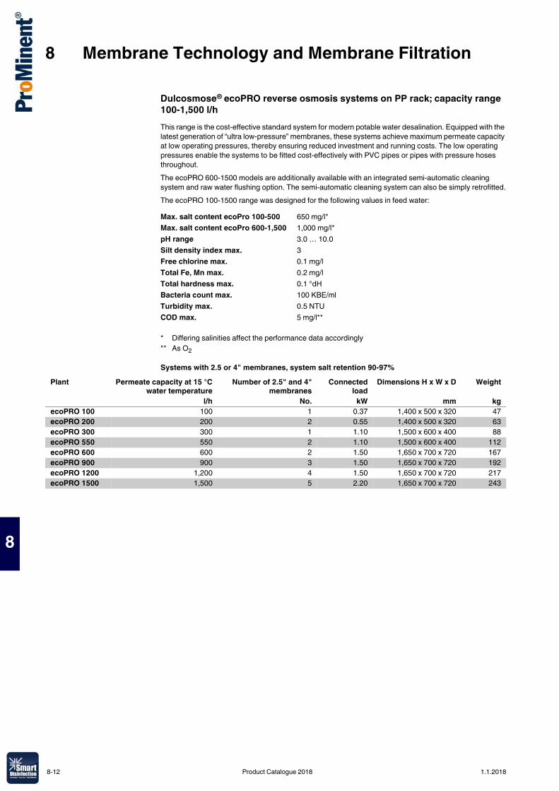
8 Membrane Technology and Membrane Filtration
8
Dulcosmose® ecoPRO reverse osmosis systems on PP rack; capacity range 100-1,500 l/hThis range is the cost-effective standard system for modern potable water desalination. Equipped with the latest generation of “ultra low-pressure” membranes, these systems achieve maximum permeate capacity at low operating pressures, thereby ensuring reduced investment and running costs. The low operating pressures enable the systems to be fitted cost-effectively with PVC pipes or pipes with pressure hoses throughout.The ecoPRO 600-1500 models are additionally available with an integrated semi-automatic cleaning system and raw water flushing option. The semi-automatic cleaning system can also be simply retrofitted.The ecoPRO 100-1500 range was designed for the following values in feed water:
Systems with 2.5 or 4" membranes, system salt retention 90-97%
Max. salt content ecoPro 100-500 650 mg/l*Max. salt content ecoPro 600-1,500 1,000 mg/l*pH range 3.0 … 10.0Silt density index max. 3Free chlorine max. 0.1 mg/lTotal Fe, Mn max. 0.2 mg/lTotal hardness max. 0.1 °dHBacteria count max. 100 KBE/mlTurbidity max. 0.5 NTUCOD max. 5 mg/l**
* Differing salinities affect the performance data accordingly** As O2
Plant Permeate capacity at 15 °Cwater temperature
Number of 2.5" and 4"membranes
Connectedload
Dimensions H x W x D Weight
l/h No. kW mm kgecoPRO 100 100 1 0.37 1,400 x 500 x 320 47ecoPRO 200 200 2 0.55 1,400 x 500 x 320 63ecoPRO 300 300 1 1.10 1,500 x 600 x 400 88ecoPRO 550 550 2 1.10 1,500 x 600 x 400 112ecoPRO 600 600 2 1.50 1,650 x 700 x 720 167ecoPRO 900 900 3 1.50 1,650 x 700 x 720 192ecoPRO 1200 1,200 4 1.50 1,650 x 700 x 720 217ecoPRO 1500 1,500 5 2.20 1,650 x 700 x 720 243
8-12 Product Catalogue 2018 1.1.2018
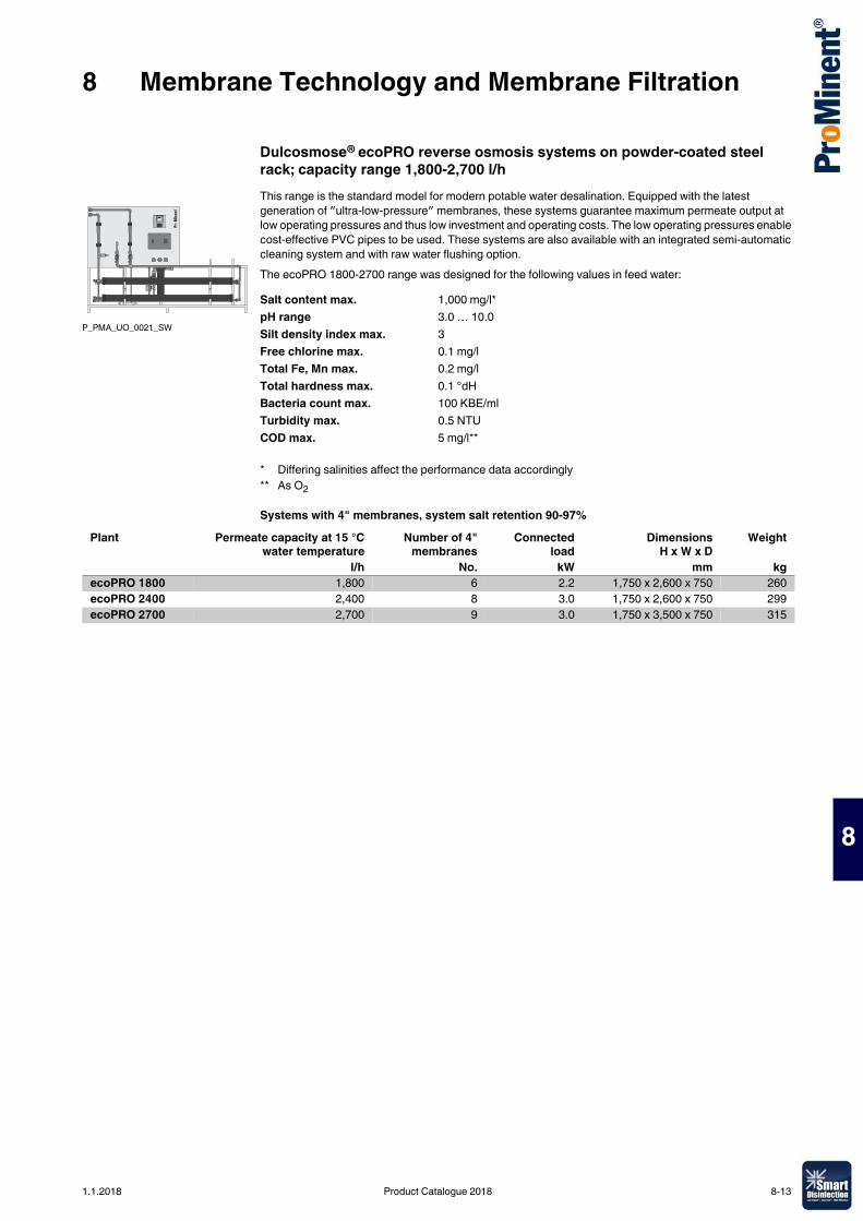
8 Membrane Technology and Membrane Filtration
8
Dulcosmose® ecoPRO reverse osmosis systems on powder-coated steel rack; capacity range 1,800-2,700 l/hThis range is the standard model for modern potable water desalination. Equipped with the latest generation of ″ultra-low-pressure″ membranes, these systems guarantee maximum permeate output at low operating pressures and thus low investment and operating costs. The low operating pressures enable cost-effective PVC pipes to be used. These systems are also available with an integrated semi-automatic cleaning system and with raw water flushing option.The ecoPRO 1800-2700 range was designed for the following values in feed water:
Systems with 4" membranes, system salt retention 90-97%
P_PMA_UO_0021_SW
Salt content max. 1,000 mg/l*pH range 3.0 … 10.0Silt density index max. 3Free chlorine max. 0.1 mg/lTotal Fe, Mn max. 0.2 mg/lTotal hardness max. 0.1 °dHBacteria count max. 100 KBE/mlTurbidity max. 0.5 NTUCOD max. 5 mg/l**
* Differing salinities affect the performance data accordingly** As O2
Plant Permeate capacity at 15 °Cwater temperature
Number of 4"membranes
Connectedload
DimensionsH x W x D
Weight
l/h No. kW mm kgecoPRO 1800 1,800 6 2.2 1,750 x 2,600 x 750 260ecoPRO 2400 2,400 8 3.0 1,750 x 2,600 x 750 299ecoPRO 2700 2,700 9 3.0 1,750 x 3,500 x 750 315
1.1.2018 Product Catalogue 2018 8-13
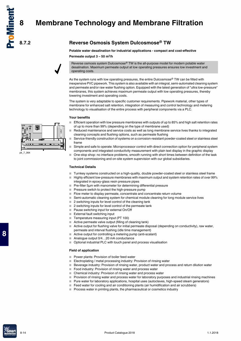
8 Membrane Technology and Membrane Filtration
8
8.7.2 Reverse Osmosis System Dulcosmose® TWPotable water desalination for industrial applications - compact and cost-effectivePermeate output 3 – 50 m3/h
As the system runs with low operating pressures, the entire Dulcosmose® TW can be fitted with inexpensive PVC pipework. This system is also available with an integral, semi-automated cleaning system and permeate and/or raw water flushing option. Equipped with the latest generation of "ultra low-pressure" membranes, this system achieves maximum permeate output with low operating pressures, thereby lowering investment and operating costs.The system is very adaptable to specific customer requirements. Pipework material, other types of membrane for enhanced salt retention, integration of measuring and control technology and metering technology to visualisation of the entire process with peripheral components via a PLC.
Your benefits� Efficient operation with low pressure membranes with outputs of up to 85% and high salt retention rates
of up to more than 99% (depending on the type of membrane used)� Reduced maintenance and service costs as well as long membrane service lives thanks to integrated
cleaning concepts and flushing options, such as permeate flushing� Service-friendly construction of systems on a corrosion-resistant powder-coated steel or stainless steel
frame� Simple and safe to operate: Microprocessor control with direct connection option for peripheral system
components and integrated conductivity measurement with plain text display in the graphic display� One-stop shop: no interface problems, smooth running with short times between definition of the task
to joint commissioning and on-site system supervision with our global subsidiaries.
Technical Details� Turnkey systems constructed on a high-quality, double powder-coated steel or stainless steel frame� Highly efficient low-pressure membranes with maximum output and system retention rates of over 99%
integrated in epoxy-glass resin pressure pipes� Pre-filter 5µm with manometer for determining differential pressure� Pressure switch to protect the high-pressure pump� Flow meter to display permeate, concentrate and concentrate return volume� Semi-automatic cleaning system for chemical module cleaning for long module service lives� 2 switching inputs for level control of the cleaning tank� 2 switching inputs for level control of the permeate tank� Pause switching input for external On/Off� External fault switching input� Temperature measuring input (PT 100)� Active permeate valve output (filling of cleaning tank)� Active output for flushing valve for initial permeate disposal (depending on conductivity), raw water,
permeate and interval flushing (idle time management)� Active output for controlling a metering pump (anti-scalant)� Analogue output 0/4…20 mA conductance� Optional industrial PLC with touch panel and process visualisation
Field of application� Power plants: Provision of boiler feed water� Electroplating / metal processing industry: Provision of rinsing water� Beverage industry: Provision of rinsing water, product water and process and return dilution water� Food industry: Provision of rinsing water and process water� Chemical industry: Provision of rinsing water and process water� Provision of rinsing water and process water for laboratory purposes and industrial rinsing machines� Pure water for laboratory applications, hospital uses (autoclaves, high-speed steam generators)� Feed water for cooling and air conditioning plants (air humidification and air scrubbers)� Process water in printing plants, the pharmaceutical or cosmetics industry
Reverse osmosis system Dulcosmose® TW is the all-purpose model for modern potable water desalination. Maximum permeate output at low operating pressures ensures low investment and operating costs.
pk_7_064
8-14 Product Catalogue 2018 1.1.2018
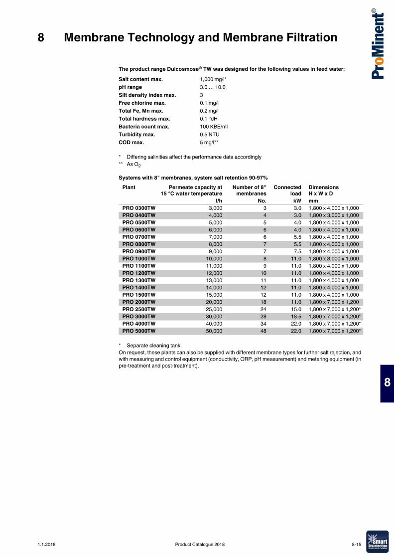
8 Membrane Technology and Membrane Filtration
8
The product range Dulcosmose® TW was designed for the following values in feed water:
Systems with 8" membranes, system salt retention 90-97%
On request, these plants can also be supplied with different membrane types for further salt rejection, and with measuring and control equipment (conductivity, ORP, pH measurement) and metering equipment (in pre-treatment and post-treatment).
Salt content max. 1,000 mg/l*pH range 3.0 … 10.0Silt density index max. 3Free chlorine max. 0.1 mg/lTotal Fe, Mn max. 0.2 mg/lTotal hardness max. 0.1 °dHBacteria count max. 100 KBE/mlTurbidity max. 0.5 NTUCOD max. 5 mg/l**
* Differing salinities affect the performance data accordingly ** As O2
Plant Permeate capacity at15 °C water temperature
Number of 8″membranes
Connectedload
Dimensions H x W x D
l/h No. kW mmPRO 0300TW 3,000 3 3.0 1,800 x 4,000 x 1,000PRO 0400TW 4,000 4 3.0 1,800 x 3,000 x 1,000PRO 0500TW 5,000 5 4.0 1,800 x 4,000 x 1,000PRO 0600TW 6,000 6 4.0 1,800 x 4,000 x 1,000PRO 0700TW 7,000 6 5.5 1,800 x 4,000 x 1,000PRO 0800TW 8,000 7 5.5 1,800 x 4,000 x 1,000PRO 0900TW 9,000 7 7.5 1,800 x 4,000 x 1,000PRO 1000TW 10,000 8 11.0 1,800 x 3,000 x 1,000PRO 1100TW 11,000 9 11.0 1,800 x 4,000 x 1,000PRO 1200TW 12,000 10 11.0 1,800 x 4,000 x 1,000PRO 1300TW 13,000 11 11.0 1,800 x 4,000 x 1,000PRO 1400TW 14,000 12 11.0 1,800 x 4,000 x 1,000PRO 1500TW 15,000 12 11.0 1,800 x 4,000 x 1,000PRO 2000TW 20,000 18 11.0 1,800 x 7,000 x 1,200PRO 2500TW 25,000 24 15.0 1,800 x 7,000 x 1,200*PRO 3000TW 30,000 28 18.5 1,800 x 7,000 x 1,200*PRO 4000TW 40,000 34 22.0 1,800 x 7,000 x 1,200*PRO 5000TW 50,000 48 22.0 1,800 x 7,000 x 1,200*
* Separate cleaning tank
1.1.2018 Product Catalogue 2018 8-15
8 Membrane Technology and Membrane Filtration
8
8.7.3 Reverse Osmosis System Dulcosmose® BW Brackish water is transformed into drinking water Permeate output 2,000 – 50,000 l/h
A reverse osmosis system of type of BW has PVC pipework on the low-pressure side. The system has high-grade stainless steel (type DIN 1.4571) on the high-pressure side. Stainless steel pipes are welded under shielding gas and a forming gas atmosphere and subsequently passivated in a pickling bath. The integrated semi-automatic cleaning system with permeate and/or raw water flushing ensures exceptionally long membrane service lives, as scaling and fouling effects are minimised. The system is very adaptable to specific customer requirements. Pipework material, other types of membrane for enhanced salt retention, integration of measuring and control technology and metering technology to visualisation of the entire process with peripheral components via a PLC.
Your benefits� Efficient operation with low pressure membranes with maximum output and salt retention rates of up to
over 99 %� Reduced maintenance and service costs as well as long membrane service lives, thanks to integrated
cleaning concepts and flushing options� Service-friendly construction of systems on a corrosion-resistant powder-coated steel or stainless steel
frame� Simple and safe to operate: Central control of the entire system by microprocessor controller or
industrial PLC with touch panel and process visualisation. � Application-optimised design taking into account economic aspects, such as the durability of the
membranes, energy efficiency and process automation� One-stop shop: no interface problems, smooth running with short times between definition of the task
to joint commissioning and on-site system supervision with our global subsidiaries
Technical Details� Turnkey systems constructed on a high-quality, double powder-coated steel or stainless steel frame. � Highly efficient low-pressure membranes with maximum output and system retention rates of over 99%
integrated in epoxy-glass resin pressure pipes� Pre-filter 5µm with manometer for determining differential pressure� Pressure switch to protect the high-pressure pump� Flow meter to display permeate, concentrate and concentrate return volume� Semi-automatic cleaning system for chemical module cleaning for long module service lives � 2 switching inputs for level control of the cleaning tank� 2 switching inputs for level control of the permeate tank� Pause switching input for external On/Off� External fault switching input� Temperature measuring input (Pt 100)� Active permeate valve output (filling of cleaning tank)� Active output for flushing valve for initial permeate disposal (depending on conductivity), raw water,
permeate and interval flushing (idle time management)� Active output for controlling a metering pump (anti-scalant)� Analogue output 0/4…20 mA conductance� Optional industrial PLC with touch panel and process visualisation
Field of application
� Decentralised, public or private supply of potable water.
Reverse osmosis system Dulcosmose® BW is the standard model for the modern desalination of brackish water. Equipped with the latest generation of "high rejection low-pressure" membranes, this system achieves maximum permeate output with moderate operating pressures, thereby lowering investment and operating costs.
pk_7_065
8-16 Product Catalogue 2018 1.1.2018
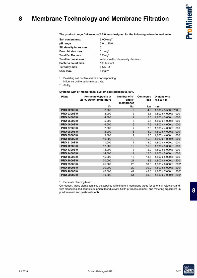
8 Membrane Technology and Membrane Filtration
8
The product range Dulcosmose® BW was designed for the following values in feed water:
Systems with 8" membranes, system salt retention 95-99%
On request, these plants can also be supplied with different membrane types for other salt rejection, and with measuring and control equipment (conductivity, ORP, pH measurement) and metering equipment (in pre-treatment and post-treatment).
Salt content max. 5,000 mg/l*pH range 3.0 … 10.0Silt density index max. 3Free chlorine max. 0.1 mg/lTotal Fe, Mn max. 0.2 mg/lTotal hardness max. water must be chemically stabilisedBacteria count max. 100 KBE/mlTurbidity max. 0.5 NTUCOD max. 5 mg/l**
* Deviating salt contents have a corresponding influence on the performance data.
** As O2
Plant Permeate capacity at25 °C water temperature
Number of 4″and 8″
membranes
Connectedload
Dimensions H x W x D
l/h No. kW mmPRO 0200BW 2,000 9 4.0 1,800 x 3,500 x 750PRO 0300BW 3,000 3 5.5 1,800 x 4,000 x 1,000PRO 0400BW 4,000 4 5.5 1,800 x 3,000 x 1,000PRO 0500BW 5,000 5 5.5 1,800 x 4,000 x 1,000PRO 0600BW 6,000 6 7.5 1,800 x 4,000 x 1,000PRO 0700BW 7,000 7 7.5 1,800 x 4,000 x 1,000PRO 0800BW 8,000 8 15.0 1,800 x 4,000 x 1,000PRO 0900BW 9,000 9 15.0 1,800 x 4,000 x 1,000PRO 1000BW 10,000 10 15.0 1,800 x 4,000 x 1,000PRO 1100BW 11,000 11 15.0 1,800 x 4,000 x 1,000PRO 1200BW 12,000 12 15.0 1,800 x 5,000 x 1,000PRO 1300BW 13,000 13 15.0 1,800 x 6,000 x 1,000PRO 1400BW 14,000 14 15.0 1,800 x 5,000 x 1,000PRO 1500BW 15,000 15 18.5 1,800 x 5,000 x 1,000PRO 2000BW 20,000 21 18.5 1,800 x 6,000 x 1,200PRO 2500BW 25,000 26 30.0 1,800 x 6,000 x 1,200*PRO 3000BW 30,000 29 30.0 1,800 x 6,000 x 1,200*PRO 4000BW 40,000 42 45.0 1,800 x 7,000 x 1,200*PRO 5000BW 50,000 51 60.0 1,800 x 7,000 x 1,200*
* Separate cleaning tank
1.1.2018 Product Catalogue 2018 8-17
8 Membrane Technology and Membrane Filtration
8
8.7.4 Reverse Osmosis System Dulcosmose® SW Salt water is transformed into drinking water.Permeate output 780 – 29,000 l/h
A reverse osmosis system of type of SW has PVC pipework on the low-pressure side. The high-pressure side of the system has a potable water-compatible, highly corrosion-resistant inner seal due to the high NaCI content. The integrated semi-automatic cleaning system with permeate and/or raw water flushing ensures exceptionally long membrane service lives, as scaling and fouling effects are minimised. The system can be adapted with ease to specific customer requirements. Pipework material, other types of membrane for enhanced salt retention, integration of measuring and control technology and metering technology to visualisation of the entire process with peripheral components via a PLC. Everything can be selected at random. Optional for all systems: They can be fitted with a system for energy recovery from the concentrate flow. The latest generation of what are known as pressure controllers is used.
Your benefits� Integrated energy recovery system based on state-of-the-art pressure controllers� Efficient operation with low pressure membranes with outputs of up to 50% and high salt retention rates
of up to over 99%� Reduced maintenance and service costs as well as long membrane service lives, thanks to integrated
cleaning concepts and flushing options� Service-friendly construction of systems on a corrosion-resistant powder-coated steel or stainless steel
frame� Simple and safe to operate: Central control of the entire system by microprocessor controller or
industrial PLC with touch panel and process visualisation� Application-optimised design taking into account economic aspects, such as the durability of the
membranes, energy efficiency and process automation� One-stop shop: no interface problems, smooth running with short times between definition of the task
to joint commissioning and on-site system supervision with our global subsidiaries
Technical Details� Turnkey systems constructed on a high-quality, double powder-coated steel or stainless steel frame� Highly efficient low-pressure membranes with maximum output and system retention rates of over 99%
integrated in epoxy-glass resin pressure pipes� Pre-filter 5µm with manometer for determining differential pressure� Pressure switch to protect the high-pressure pump� Flow meter to display permeate and concentrate volume� Semi-automatic cleaning system for chemical module cleaning for long module service lives � Central PLC of the entire system and peripheral components, adapted to customer requirements
Field of application
� Decentralised, public or private supply of potable water.
The product range Dulcosmose® SW was designed for the following values in feed water:
The reverse osmosis system Dulcosmose® SW is the standard model for modern desalination of salt water. Equipped with the latest generation of "high rejection low-pressure" membranes, this system achieves maximum permeate output with moderate operating pressures, thereby lowering investment and operating costs.
pk_7_074
Salt content max. 40,000 mg/l*pH range 3.0 … 10.0Silt density index max. 3Free chlorine max. 0.1 mg/lTotal Fe, Mn max. 0.2 mg/lTotal hardness max. water must be chemically stabilisedBacteria count max. 100 KBE/mlTurbidity max. 0.5 NTUCOD max. 5 mg/l**
* Differing salinities affect the performance data accordingly** As O2
8-18 Product Catalogue 2018 1.1.2018
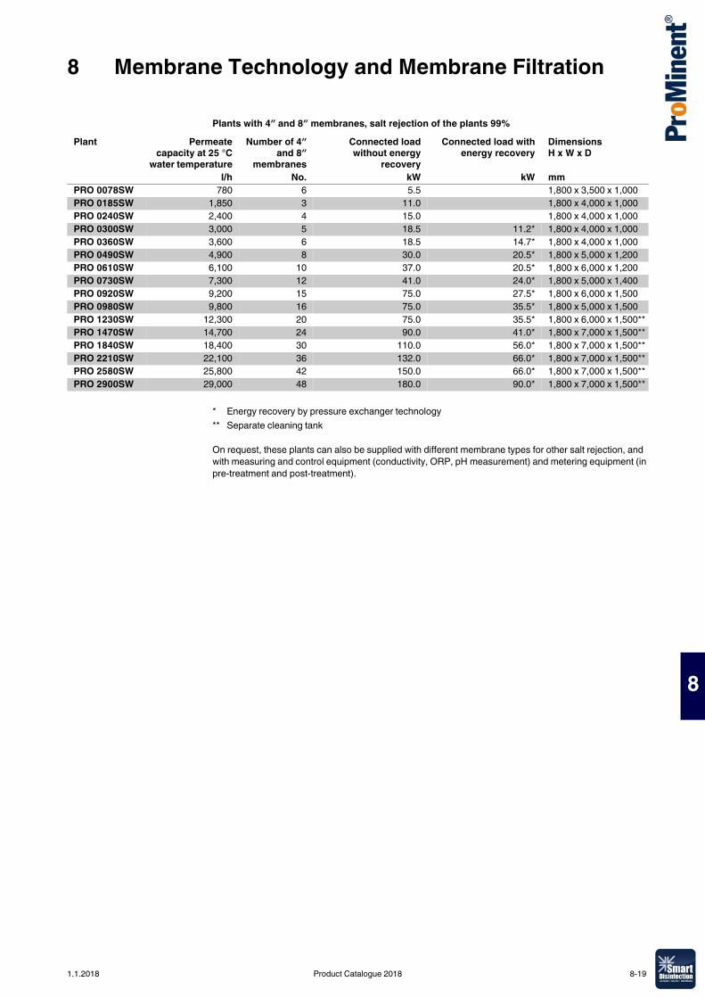
8 Membrane Technology and Membrane Filtration
8
Plants with 4″ and 8″ membranes, salt rejection of the plants 99%
On request, these plants can also be supplied with different membrane types for other salt rejection, and with measuring and control equipment (conductivity, ORP, pH measurement) and metering equipment (in pre-treatment and post-treatment).
Plant Permeatecapacity at 25 °C
water temperature
Number of 4″and 8″
membranes
Connected loadwithout energy
recovery
Connected load withenergy recovery
Dimensions H x W x D
l/h No. kW kW mmPRO 0078SW 780 6 5.5 1,800 x 3,500 x 1,000PRO 0185SW 1,850 3 11.0 1,800 x 4,000 x 1,000PRO 0240SW 2,400 4 15.0 1,800 x 4,000 x 1,000PRO 0300SW 3,000 5 18.5 11.2* 1,800 x 4,000 x 1,000PRO 0360SW 3,600 6 18.5 14.7* 1,800 x 4,000 x 1,000PRO 0490SW 4,900 8 30.0 20.5* 1,800 x 5,000 x 1,200PRO 0610SW 6,100 10 37.0 20.5* 1,800 x 6,000 x 1,200PRO 0730SW 7,300 12 41.0 24.0* 1,800 x 5,000 x 1,400PRO 0920SW 9,200 15 75.0 27.5* 1,800 x 6,000 x 1,500PRO 0980SW 9,800 16 75.0 35.5* 1,800 x 5,000 x 1,500PRO 1230SW 12,300 20 75.0 35.5* 1,800 x 6,000 x 1,500**PRO 1470SW 14,700 24 90.0 41.0* 1,800 x 7,000 x 1,500**PRO 1840SW 18,400 30 110.0 56.0* 1,800 x 7,000 x 1,500**PRO 2210SW 22,100 36 132.0 66.0* 1,800 x 7,000 x 1,500**PRO 2580SW 25,800 42 150.0 66.0* 1,800 x 7,000 x 1,500**PRO 2900SW 29,000 48 180.0 90.0* 1,800 x 7,000 x 1,500**
* Energy recovery by pressure exchanger technology** Separate cleaning tank
1.1.2018 Product Catalogue 2018 8-19
8 Membrane Technology and Membrane Filtration
8
8-20 Product Catalogue 2018 1.1.2018


ProducOrder yoHow you
www.promine
www.promine
www.promine
Ma
Ms
t catalogue 2018 ur personal copy. want it, when you want it.
nt.com/app
nt.com/en/product-catalogue
nt.com/en/catalogue-request
etering pumps, componentsnd metering systems
easuring, control andensor technology
Motor-driven and process metering pumps for all capacity ranges
Water treatment and water disinfection