Water-Source Heat Pump Systems - RSES Long Beach
75
1 Water-Source Heat Pump Systems (TRC015EN.PPT) © 2000 American Standard Inc. All rights reserved Water-Source Heat Pump Systems A Trane Air Conditioning Clinic © American Standard Inc. 2000 Air Conditioning Clinic TRG-TRC015-EN The Trane Company believes that it is incumbent on manufacturers to serve the industry by regularly disseminating information gathered through laboratory research, testing programs, and field experience. The Trane Air Conditioning Clinic series is one means of knowledge sharing. It is intended to acquaint a nontechnical audience with various fundamental aspects of heating, ventilating, and air conditioning. We have taken special care to make the clinic as uncommercial and straightforward as possible. Illustrations of Trane products only appear in cases where they help convey the message contained in the accompanying text. This particular clinic introduces the reader to water-source heat pump systems.
Transcript of Water-Source Heat Pump Systems - RSES Long Beach

1Water-Source Heat Pump Systems (TRC015EN.PPT)© 2000 American Standard Inc. All rights reserved
Water-Source Heat Pump SystemsA Trane Air Conditioning Clinic
© American Standard Inc. 2000 Air Conditioning Clinic TRG-TRC015-ENAir Conditioning Clinic TRG-TRC015-EN
The Trane Company believes that it is incumbent on manufacturers to serve the industry by regularly disseminating information gathered through laboratory research, testing programs, and field experience.
The Trane Air Conditioning Clinic series is one means of knowledge sharing. It is intended to acquaint a nontechnical audience with various fundamental aspects of heating, ventilating, and air conditioning. We have taken special care to make the clinic as uncommercial and straightforward as possible. Illustrations of Trane products only appear in cases where they help convey the message contained in the accompanying text.
This particular clinic introduces the reader to water-source heat pump systems.

2Water-Source Heat Pump Systems (TRC015EN.PPT)© 2000 American Standard Inc. All rights reserved
period oneWhat Is a Heat Pump?
© American Standard Inc. 2000
Water-Source Heat Pump Systems
Air Conditioning Clinic TRG-TRC015-ENAir Conditioning Clinic TRG-TRC015-EN
A heat pump is a self-contained, packaged cooling-and-heating unit with a reversible refrigeration cycle. To better explain the concept of a reversible cycle, we will review the basic vapor-compression refrigeration cycle.

3Water-Source Heat Pump Systems (TRC015EN.PPT)© 2000 American Standard Inc. All rights reserved
Air Conditioning Clinic TRG-TRC015-ENAir Conditioning Clinic TRG-TRC015-EN© American Standard Inc. 2000
Vapor-Compression Refrigeration
expansionexpansiondevicedevice
condensercondenser
compressorcompressor
evaporatorevaporatorA B
CD
Refrigerant enters the evaporator in the form of a cool, low-pressure mixture of liquid and vapor (A). Heat is transferred to the refrigerant from the relatively warm air or water to be cooled, causing the liquid refrigerant to boil. The resulting vapor (B) is then pumped from the evaporator by the compressor, which increases the pressure and temperature of the refrigerant vapor.
The resulting hot, high-pressure refrigerant vapor (C) enters the condenser where heat is transferred to ambient air or water, which is at a lower temperature. Inside the condenser, the refrigerant condenses into a liquid.
This liquid refrigerant (D) then flows from the condenser to the expansion device. The expansion device creates a pressure drop that reduces the pressure of the refrigerant to that of the evaporator. At this low pressure, a small portion of the refrigerant boils (or flashes), cooling the remaining liquid refrigerant to the desired evaporator temperature. The cool mixture of liquid and vapor refrigerant (A) travels to the evaporator to repeat the cycle.

4Water-Source Heat Pump Systems (TRC015EN.PPT)© 2000 American Standard Inc. All rights reserved
Air Conditioning Clinic TRG-TRC015-ENAir Conditioning Clinic TRG-TRC015-EN© American Standard Inc. 2000
Heat Pump in Cooling Mode
compressorcompressorrefrigerantrefrigerant--toto--airairheat exchangerheat exchanger
reversingreversingvalvevalve
expansionexpansiondevicedevice
refrigerantrefrigerant--toto--waterwaterheat exchangerheat exchanger
waterwaterlooploop
A heat pump is basically a device that transfers heat from one substance to another substance. It has these same basic refrigeration components: compressor, condenser, evaporator, and expansion device. The difference is that it can also reverse the refrigeration cycle to perform heating, as well as cooling, by reversing the functions of the two heat exchangers. The operation of the refrigeration cycle changes depending on whether the unit is in cooling or heating mode.
The type of heat pump shown here transfers heat from air to water and vice versa. In the cooling mode, it operates the same as the refrigeration cycle we just reviewed. Hot, high-pressure refrigerant vapor is pumped from the compressor to the refrigerant-to-water heat exchanger that, in the cooling mode, functions as the condenser. Inside this heat exchanger, heat is transferred from the refrigerant vapor to the lower-temperature water, and the refrigerant condenses into a liquid.
The liquid refrigerant then flows through an expansion device that reduces the pressure and temperature of the refrigerant. The resulting mixture of cool liquid and vapor travels to the refrigerant-to-air heat exchanger that, in the cooling mode, functions as the evaporator. Inside this heat exchanger, the refrigerant absorbs heat from the relatively warm air, cooling the air and causing the liquid refrigerant to boil. The resulting refrigerant vapor is then pumped back to the compressor, which increases its pressure and temperature to repeat the cycle.

5Water-Source Heat Pump Systems (TRC015EN.PPT)© 2000 American Standard Inc. All rights reserved
Air Conditioning Clinic TRG-TRC015-ENAir Conditioning Clinic TRG-TRC015-EN© American Standard Inc. 2000
Heat Pump in Heating Mode
compressorcompressor
refrigerantrefrigerant--toto--waterwaterheat exchangerheat exchanger
refrigerantrefrigerant--toto--airairheat exchangerheat exchanger
expansionexpansiondevicedevice
waterwaterlooploop
reversingreversingvalvevalve
A heat pump includes a reversing valve that allows it to also function in the heating mode.
In the heating mode, hot, high-pressure refrigerant vapor is pumped from the compressor, and diverted by this reversing valve to the refrigerant-to-air heat exchanger. In the heating mode, this heat exchanger functions as the condenser, and heat is transferred from the refrigerant vapor to the lower temperature air. The air is heated and the refrigerant condenses into a liquid.
The liquid refrigerant then flows through the expansion device and travels to the refrigerant-to-water heat exchanger that, in the heating mode, now functions as the evaporator. Inside the refrigerant-to-water heat exchanger, the refrigerant absorbs heat from the relatively warm water, causing the liquid refrigerant to boil. The refrigerant vapor travels back through the reversing valve to the compressor to repeat the cycle.
The reversing valve, piping, and controls inside the heat pump allows it to perform both cooling and heating functions.
6Water-Source Heat Pump Systems (TRC015EN.PPT)© 2000 American Standard Inc. All rights reserved
Air Conditioning Clinic TRG-TRC015-ENAir Conditioning Clinic TRG-TRC015-EN© American Standard Inc. 2000
Types of Heat Pumps
waterwater--source heat pumpssource heat pumps
airair--source heat pumpssource heat pumps
waterwater--toto--water heat pumpwater heat pump
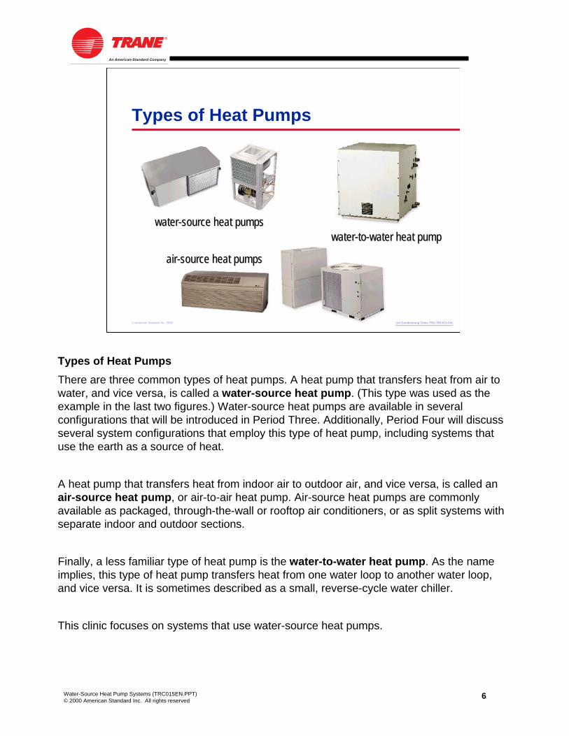
Types of Heat PumpsThere are three common types of heat pumps. A heat pump that transfers heat from air to water, and vice versa, is called a water-source heat pump. (This type was used as the example in the last two figures.) Water-source heat pumps are available in several configurations that will be introduced in Period Three. Additionally, Period Four will discuss several system configurations that employ this type of heat pump, including systems that use the earth as a source of heat.
A heat pump that transfers heat from indoor air to outdoor air, and vice versa, is called an air-source heat pump, or air-to-air heat pump. Air-source heat pumps are commonly available as packaged, through-the-wall or rooftop air conditioners, or as split systems with separate indoor and outdoor sections.
Finally, a less familiar type of heat pump is the water-to-water heat pump. As the name implies, this type of heat pump transfers heat from one water loop to another water loop, and vice versa. It is sometimes described as a small, reverse-cycle water chiller.
This clinic focuses on systems that use water-source heat pumps.

7Water-Source Heat Pump Systems (TRC015EN.PPT)© 2000 American Standard Inc. All rights reserved
Air Conditioning Clinic TRG-TRC015-ENAir Conditioning Clinic TRG-TRC015-EN© American Standard Inc. 2000
Water-Source Heat Pump
refrigerantrefrigerant--toto--waterwaterheat exchangerheat exchanger
refrigerantrefrigerant--toto--airairheat exchangerheat exchanger
compressorcompressor
reversingreversingvalvevalve
expansionexpansiondevicedevicefanfan
Components of a Water-Source Heat PumpThe refrigeration circuit of a water-source heat pump is comprised of the following basic components: compressor, refrigerant-to-air heat exchanger, refrigerant-to-water heat exchanger, expansion device, and reversing valve. The refrigeration circuit is pre-engineered and assembled in a factory. No field-installed refrigerant piping is required.
Additionally, each water-source heat pump includes a fan (sometimes called a blower) to move air through the refrigerant-to-air heat exchanger, an air filter, unit-level controls, and possibly a few optional accessories depending on the application.

8Water-Source Heat Pump Systems (TRC015EN.PPT)© 2000 American Standard Inc. All rights reserved
Air Conditioning Clinic TRG-TRC015-ENAir Conditioning Clinic TRG-TRC015-EN© American Standard Inc. 2000
Compressor
rotaryrotary(rolling piston)(rolling piston)
reciprocatingreciprocating
scrollscroll
Each heat pump includes at least one compressor. Some higher-capacity models may use multiple compressors. Depending on its size and manufacturer, this compressor may be rotary (rolling piston), reciprocating, or scroll type. The selection of the type of compressor generally depends on the capacity and electrical requirements of the heat pump.

9Water-Source Heat Pump Systems (TRC015EN.PPT)© 2000 American Standard Inc. All rights reserved
Air Conditioning Clinic TRG-TRC015-ENAir Conditioning Clinic TRG-TRC015-EN© American Standard Inc. 2000
Refrigerant-to-Air Heat Exchanger
refrigerantrefrigerant--toto--airairheat exchangerheat exchanger
The refrigerant-to-air heat exchanger is a finned-tube coil similar to a direct-expansion (DX) refrigerant coil found in a packaged rooftop unit or air handler.
In the cooling mode, the refrigerant-to-air heat exchanger acts as the evaporator, and the refrigerant inside the tubes absorbs heat from the air flowing through it. In the heating mode, it acts as the condenser, and the refrigerant rejects heat to the air.
As a side note, in the heating mode, a water-source heat pump is capable of supplying air at approximately 100ºF [38ºC]. This air is generally warm enough to avoid down-drafts in perimeter spaces when delivered through ceiling diffusers.

10Water-Source Heat Pump Systems (TRC015EN.PPT)© 2000 American Standard Inc. All rights reserved
Air Conditioning Clinic TRG-TRC015-ENAir Conditioning Clinic TRG-TRC015-EN© American Standard Inc. 2000
Refrigerant-to-Water Heat Exchanger
coaxialcoaxialrefrigerantrefrigerant--toto--waterwaterheat exchangerheat exchanger
The refrigerant-to-water heat exchanger may be a tube-in-tube, tube-in-shell, or brazed-plate design. The example shown here is a tube-in-tube, or coaxial, heat exchanger. It is constructed as a small tube running inside another larger tube. The water flows through the inner tube and refrigerant flows through the outer tube.
In the cooling mode, the refrigerant-to-water heat exchanger acts as the condenser. The water flowing through the inner tube absorbs heat from the refrigerant flowing through the outer tube. In the heating mode, it acts as the evaporator and the refrigerant absorbs heat from the water.

11Water-Source Heat Pump Systems (TRC015EN.PPT)© 2000 American Standard Inc. All rights reserved
Air Conditioning Clinic TRG-TRC015-ENAir Conditioning Clinic TRG-TRC015-EN© American Standard Inc. 2000
Expansion Device
thermalthermalexpansionexpansionvalve (TXV)valve (TXV)
A variety of expansion devices may be used in water-source heat pumps. Selection is made by the manufacturer. The most common types are thermal expansion valves (TXV), electronic expansion valves, short orifices, and capillary tubes.
All of these devices reduce the pressure and temperature of the refrigerant within the cycle. Expansion valves, such as the TXV shown here, have the added capability of metering the quantity of refrigerant flowing through the cycle in order to match the load. This enhances the efficiency of the cycle. TXVs used in heat pumps may be bi-directional, meaning that the refrigerant flows in one direction when in cooling mode and in the opposite direction when in heating mode. The alternative would be to design the refrigerant piping inside the heat pump to ensure that refrigerant flow through the valve is in the same direction in either mode.

12Water-Source Heat Pump Systems (TRC015EN.PPT)© 2000 American Standard Inc. All rights reserved
Air Conditioning Clinic TRG-TRC015-ENAir Conditioning Clinic TRG-TRC015-EN© American Standard Inc. 2000
Reversing Valve
reversingreversingvalvevalverefrigerantrefrigerant--toto--airair
heat exchangerheat exchanger
The reversing valve, sometimes called a four-way valve, is the component that allows the heat pump to perform heating as well as cooling. It is called a reversing valve because it is used to reverse the direction of refrigerant flow through the cycle. In the heating mode, refrigerant vapor from the compressor is diverted by the reversing valve to the refrigerant-to-air heat exchanger. In this heat exchanger, heat is transferred from the refrigerant vapor to the air, heating the air.

13Water-Source Heat Pump Systems (TRC015EN.PPT)© 2000 American Standard Inc. All rights reserved
Air Conditioning Clinic TRG-TRC015-ENAir Conditioning Clinic TRG-TRC015-EN© American Standard Inc. 2000
Unit-Level Controls
Space temperature controlNight setbackRandom startAnti-short-cycle timer
heatheatpumppump
thermostatthermostat
Each space or zone in a building is served by a heat pump. Each heat pump must be able to respond to the cooling or heating demands of its space. This is often accomplished by using a conventional thermostat to control the operation of the heat pump.
Unit-level controls at each heat pump may also include the following fuctions:
• Night setback uses a time clock to change the temperature set point of the space in order to save energy at night.
• Random start is a feature that attempts to minimize the building’s electrical demand by randomly, rather than simultaneously, turning on heat pumps in the morning to warm up or cool down their respective spaces.
• Anti-short-cycle timers are used to reduce the cycling on and off of the compressor.
Use of direct digital controls (DDC) allows the monitoring of several additional control points and communication with a centralized building automation system (BAS) for optimized system control. System-level control issues will be discussed in Period Three.

14Water-Source Heat Pump Systems (TRC015EN.PPT)© 2000 American Standard Inc. All rights reserved
period twoWhat Is a Water-Source Heat Pump System?
© American Standard Inc. 2000
Water-Source Heat Pump Systems
Air Conditioning Clinic TRG-TRC015-ENAir Conditioning Clinic TRG-TRC015-EN
This next period will discuss the operation, benefits, and issues of a water-source heat pump (WSHP) system. Several variations of this system will be discussed in Period Four. During Period Two we will use a traditional water-source heat pump system, which has a cooling tower and boiler, as an example.

15Water-Source Heat Pump Systems (TRC015EN.PPT)© 2000 American Standard Inc. All rights reserved
Air Conditioning Clinic TRG-TRC015-ENAir Conditioning Clinic TRG-TRC015-EN© American Standard Inc. 2000
Water-Source Heat Pump Systemcooling towercooling tower
pumpspumps
plateplate--andand--frameframeheat exchangerheat exchanger
heat pumpsheat pumps
waterwaterdistributiondistributionlooploopboilerboiler
expansionexpansiontanktank
airairseparatorseparator
Water-source heat pumps are frequently used in multiple-space commercial buildings. Each space in the building is served by one or more heat pumps. A water distribution system connects all of the heat pumps to a common, closed, water loop.
In addition to the heat pumps themselves, this system includes the following components:
• A “heat rejecter” (or “water cooler”) – a cooling tower in this example.
• A “heat adder” (or “water heater”) – a boiler in this example.
• A water distribution loop consisting of piping, pumps, air separator, expansion tank, and related accessories.
Each of these components will be discussed further in Period Three.
Period Four will introduce ground-source heat pump systems, which use the earth, rather than a cooling tower and boiler, as the heat rejecter and heat adder.

16Water-Source Heat Pump Systems (TRC015EN.PPT)© 2000 American Standard Inc. All rights reserved
Air Conditioning Clinic TRG-TRC015-ENAir Conditioning Clinic TRG-TRC015-EN© American Standard Inc. 2000
Summer Operation
9090ººFF[32[32ººC]C]
heat pumps inheat pumps incooling modecooling mode
cooling towercooling toweronon
boiler offboiler off
System OperationWater-source heat pumps can run in either heating or cooling mode when the water loop temperature is maintained between 60ºF [16ºC] and 90ºF [32ºC]. During warm weather, when all the heat pumps are operating in cooling mode, heat removed from the air is transferred to the water loop. This causes the temperature of the water in the loop to rise, making it necessary to remove heat from the water. A cooling tower or evaporative water cooler rejects this heat to the outdoor air, maintaining a leaving-water temperature of approximately 90ºF [32ºC].

17Water-Source Heat Pump Systems (TRC015EN.PPT)© 2000 American Standard Inc. All rights reserved
Air Conditioning Clinic TRG-TRC015-ENAir Conditioning Clinic TRG-TRC015-EN© American Standard Inc. 2000
Winter Operation
heat pumps inheat pumps inheating modeheating mode
6060ººFF[16[16ººC]C]boiler onboiler on
cooling towercooling toweroffoff
During cold weather, when most of the heat pumps are operating in heating mode, heat is removed from the water loop and transferred to the air. This causes the temperature of the water in the loop to drop, making it necessary to add heat to the water loop. A boiler or water heater adds heat to the water loop, maintaining a leaving-water temperature of approximately 60ºF [16ºC].

18Water-Source Heat Pump Systems (TRC015EN.PPT)© 2000 American Standard Inc. All rights reserved
Air Conditioning Clinic TRG-TRC015-ENAir Conditioning Clinic TRG-TRC015-EN© American Standard Inc. 2000
Spring and Fall Operationcooling towercooling tower
offoff
boiler offboiler off
heat pumps inheat pumps inheating modeheating modeheat pumps inheat pumps in
cooling modecooling mode
During mild weather, such as spring and fall, the heat pumps serving the sunny side and interior of the building operate in cooling mode and reject heat into the water loop. The heat pumps serving the shady side of the building operate in heating mode and absorb heat from the water loop. Heat rejected by the units operating in cooling mode can be used to offset the heat absorbed by the units in heating mode. If the water temperature stays between 60ºF [16ºC] and 90ºF [32ºC], neither the boiler nor the cooling tower need to operate. In this manner, a water-source heat pump system provides a form of heat recovery and an opportunity to save energy.
In applications such as office buildings, heat generated by lights, people, and office equipment may require year-round cooling in the interior spaces of the building. In these applications, the benefit of this heat recovery further reduces boiler operation during the winter months.

19Water-Source Heat Pump Systems (TRC015EN.PPT)© 2000 American Standard Inc. All rights reserved
Air Conditioning Clinic TRG-TRC015-ENAir Conditioning Clinic TRG-TRC015-EN© American Standard Inc. 2000
Benefits of a WSHP System
Heat recovery offers energy savingsIndividual space controlPerforms both cooling and heating Flexibility
Individual tenant metering
Small amount of floor space requiredUnit failure does not affect the rest of the system
BenefitsThe primary benefit of a properly used water-source heat pump system is that, when it operates in the heat recovery mode, it saves energy by reducing the operating time of the cooling tower and boiler.
Second, it is capable of controlling the space temperature in many spaces with dissimilar cooling and heating requirements. Because each independently controlled space is served by its own heat pump, it has its own thermostat to control the temperature.
Third, the same piece of equipment is used to provide both cooling and heating to the space. Even though a separate cooling tower and boiler may be included in the system, only one set of water pipes is required. This can reduce the system installation cost.
Fourth, the system offers flexibility for speculative buildings. Additional heat pumps can be installed and connected to the loop when spaces are partitioned and occupied, assuming that the cooling tower and boiler have adequate capacity. This also offers the opportunity to meter individual spaces and allow the occupants to pay the operating costs for their space only.
Fifth, a water-source heat pump system typically requires less mechanical floor space than centralized systems. This increases the rentable space and revenue in tenant-occupied buildings.
Finally, if one heat pump fails and must be replaced, it does not affect the operation of the rest of the system.

20Water-Source Heat Pump Systems (TRC015EN.PPT)© 2000 American Standard Inc. All rights reserved
Air Conditioning Clinic TRG-TRC015-ENAir Conditioning Clinic TRG-TRC015-EN© American Standard Inc. 2000
Issues of a WSHP System
VentilationAcousticsAccessibility requires coordination
IssuesLike any system, the water-source heat pump system also has some issues that must be addressed for proper application. This list includes some of the key issues often associated with this system.
First, because this system uses constant-volume terminal units to provide space-cooling and -heating, the introduction of outdoor air for ventilation may bring a few challenges. While the requirement for ventilation can be handled in various ways, for most commercial buildings a separate, ducted ventilation system is used. This will be addressed further in Period Three.
Next, because a heat pump is located in, or very close to, the occupied space and contains both a compressor and a fan, the resulting noise level in the space must be considered during system design. System design considerations for proper acoustics will be addressed in Period Six.
Finally, proper maintenance of the heat pumps requires that they be located in accessible areas. In new buildings, this requires coordination with the architect. Additionally, selecting units that make access as easy as possible increases the chance that the equipment will be properly maintained.

21Water-Source Heat Pump Systems (TRC015EN.PPT)© 2000 American Standard Inc. All rights reserved
period threeComponents of a WSHP System
© American Standard Inc. 2000
Water-Source Heat Pump Systems
Air Conditioning Clinic TRG-TRC015-ENAir Conditioning Clinic TRG-TRC015-EN
This period discusses the major components of the water-source heat pump (WSHP) system in further detail, including:
• Various configurations of water-source heat pumps
• Water distribution loop, including piping, pumps, and accessories
• Heat rejecters
• Heat adders
• Air distribution system
• Dedicated ventilation system
• System-level controls

22Water-Source Heat Pump Systems (TRC015EN.PPT)© 2000 American Standard Inc. All rights reserved
Air Conditioning Clinic TRG-TRC015-ENAir Conditioning Clinic TRG-TRC015-EN© American Standard Inc. 2000
WSHP Configurations
horizontalhorizontal
verticalverticalconsoleconsole
unit ventilatorunit ventilator
rooftoprooftop
vertical stackvertical stack
WSHP ConfigurationsPeriod One discussed the operation and components of a water-source heat pump, the primary component of this system. Water-source heat pumps are available in several configurations to suit various building types.
• Horizontal units are designed for installation in ceiling plenums, especially for spaces where floor space is at a premium. Typical applications include offices and schools.
• Vertical units are designed to be installed in separate spaces such as closets or maintenance rooms. Common applications for small vertical units include schools, apartments, condominiums, and retirement homes. Larger vertical units are generally used in spaces that are more open, such as cafeterias and gymnasiums, or used as a dedicated ventilation system to condition the outdoor air brought into the building.
• Console units are designed for installation under windows, in perimeter spaces or in entryways, where ducted systems cannot be used and floor space is not a constraint. Typical applications include offices, apartment buildings, motels, and dormitories.
• Unit-ventilator heat pumps are also designed for installation under windows where ducted systems cannot be used. They can use outdoor air for an economizer cycle, to provide free cooling when cooler outdoor air temperatures exist. Because of their rugged design, they are typically used in schools.
• Vertical-stack units are designed for corner installation in multistory buildings such as hotels, apartments, condominiums, and retirement centers, where a minimum amount of floor space is available. They are designed to be stacked above each other to minimize piping and electrical installation costs.
• Finally, rooftop heat pump units are specifically designed for roof installation in ducted systems. They are commonly used in industrial applications as replacements for existing rooftop equipment, for conditioning outdoor air brought into the building for ventilation, or in very large spaces such as cafeterias and gymnasiums.

23Water-Source Heat Pump Systems (TRC015EN.PPT)© 2000 American Standard Inc. All rights reserved
Air Conditioning Clinic TRG-TRC015-ENAir Conditioning Clinic TRG-TRC015-EN© American Standard Inc. 2000
WSHP System Serving a Hotel
horizontalhorizontalWSHPsWSHPs
verticalverticalWSHPsWSHPs
rooftoprooftopWSHPsWSHPs
verticalvertical--stackstackWSHPsWSHPs
The availability of these multiple configurations allows a single water-source heat pump system to be used in a building that has multiple spaces of varying types.
For example, this system may serve a hotel. Vertical-stack units are used to condition the guest rooms, horizontal units are used in the meeting rooms, vertical units are used in the larger meeting rooms and restaurants, and rooftop heat pump units are used for the lobby and large ballrooms. All of these different heat pump configurations can be connected to the same water loop.

24Water-Source Heat Pump Systems (TRC015EN.PPT)© 2000 American Standard Inc. All rights reserved
Air Conditioning Clinic TRG-TRC015-ENAir Conditioning Clinic TRG-TRC015-EN© American Standard Inc. 2000
Water Distribution Loopcooling towercooling tower
pumpspumps
heat pumpsheat pumps
boilerboiler
Water Distribution LoopThe individual water-source heat pumps are connected to a common water loop. This loop consists of piping, pumps, and related accessories. It is also used to connect to the heat rejecter and heat adder. In the example shown, a cooling tower is used as the heat rejecter and a boiler is used as the heat adder.
Since the water-source heat pumps can only extract or reject heat while water flows through them, the water circulating pumps play a critical role in the operation of the system. A standby pump is often installed to minimize the risk of flow loss in the water loop. In a centralized pumping system, the water circulating pumps are installed downstream of the cooling tower and boiler, and upstream of the heat pumps. This ensures positive water pressure throughout the system.
The system may be designed to use either constant- or variable-flow pumps. Constant-flow pumps operate whenever the system is on, and they deliver a constant flow of water through the loop. Variable-flow pumps take advantage of the fact that all heat pumps in the system are not always operating at the same time. For example, when a space needs neither cooling nor heating, the fan continues to circulate air to the space but the compressor turns off. A two-position valve shuts off water flow to the heat pump, so less total water flow is required in the loop. A variable-speed drive on the pump allows the pump to unload, which saves energy, and to deliver only the amount of water required by the operating heat pumps.
25Water-Source Heat Pump Systems (TRC015EN.PPT)© 2000 American Standard Inc. All rights reserved
Air Conditioning Clinic TRG-TRC015-ENAir Conditioning Clinic TRG-TRC015-EN© American Standard Inc. 2000
Direct- Versus Reverse-Return
reversereverse--returnreturndirectdirect--returnreturn
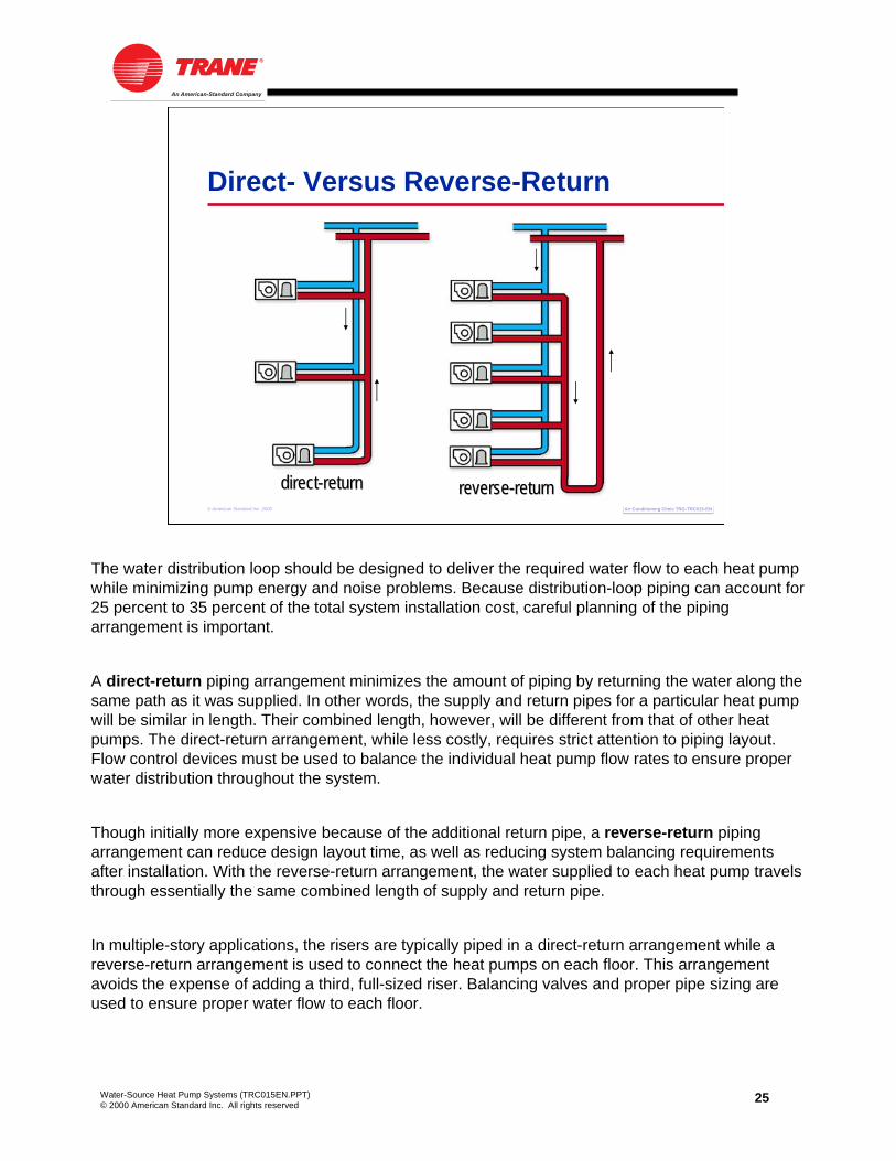
The water distribution loop should be designed to deliver the required water flow to each heat pump while minimizing pump energy and noise problems. Because distribution-loop piping can account for 25 percent to 35 percent of the total system installation cost, careful planning of the piping arrangement is important.
A direct-return piping arrangement minimizes the amount of piping by returning the water along the same path as it was supplied. In other words, the supply and return pipes for a particular heat pump will be similar in length. Their combined length, however, will be different from that of other heat pumps. The direct-return arrangement, while less costly, requires strict attention to piping layout. Flow control devices must be used to balance the individual heat pump flow rates to ensure proper water distribution throughout the system.
Though initially more expensive because of the additional return pipe, a reverse-return piping arrangement can reduce design layout time, as well as reducing system balancing requirements after installation. With the reverse-return arrangement, the water supplied to each heat pump travelsthrough essentially the same combined length of supply and return pipe.
In multiple-story applications, the risers are typically piped in a direct-return arrangement while a reverse-return arrangement is used to connect the heat pumps on each floor. This arrangement avoids the expense of adding a third, full-sized riser. Balancing valves and proper pipe sizing are used to ensure proper water flow to each floor.

26Water-Source Heat Pump Systems (TRC015EN.PPT)© 2000 American Standard Inc. All rights reserved
Air Conditioning Clinic TRG-TRC015-ENAir Conditioning Clinic TRG-TRC015-EN© American Standard Inc. 2000
Accessories
expansion tankexpansion tank
strainerstrainer
airairseparatorseparator
shutoffshutoffvalvesvalves
drain valvedrain valve
There are typically several other accessories included in the water distribution loop. These include strainers, an air separator, an expansion tank, drain valves, shutoff valves, balancing valves, and flow indicators.
A strainer is installed upstream of the inlet of each water-circulating pump to protect it from debris flowing inside the water distribution loop. In addition to proper piping design and venting, an air separator removes air that is entrained in the water distribution loop. The expansion tank accommodates the expansion and contraction of the water as temperature and, therefore, density change.
A drain valve is installed at the base of each supply riser and return riser to permit system flushing during start-up and routine servicing. Shut-off valves at each heat pump allow for easy removal or service. Additionally, balancing valves and flow indicators may be used in some systems to ensure proper water flow to each floor or to each heat pump.

27Water-Source Heat Pump Systems (TRC015EN.PPT)© 2000 American Standard Inc. All rights reserved
Air Conditioning Clinic TRG-TRC015-ENAir Conditioning Clinic TRG-TRC015-EN© American Standard Inc. 2000
Heat Rejecters
Open cooling tower with heat exchangerClosed-circuit cooling towerNatural heat sink (ground, lake)
Heat RejectersAs discussed in Period Two, a heat rejecter is used to maintain the temperature of the water in the distribution loop below approximately 90ºF [32ºC]. The three most common types of heat rejecters used in water-source heat pump systems include an open cooling tower with an intermediate heat exchanger, a closed-circuit cooling tower, and a natural heat sink such as the ground or a lake. This section will focus on the first two types of heat rejecters, and natural heat sinks will be discussed in Period Four.

28Water-Source Heat Pump Systems (TRC015EN.PPT)© 2000 American Standard Inc. All rights reserved
Air Conditioning Clinic TRG-TRC015-ENAir Conditioning Clinic TRG-TRC015-EN© American Standard Inc. 2000
Open Tower with a Heat Exchanger
waterwaterdistributiondistributionlooploop
sumpsump
propeller fanpropeller fan
outdooroutdoorairair
fillfill
pumppump plateplate--andand--frameframeheat exchangerheat exchanger
In an open cooling tower, relatively warm water is sprayed over the fill inside the tower while a fan draws outdoor air upward through the fill. The movement of air through the spray causes some of the water to evaporate, a process that cools the remaining water before it falls into the tower sump. This cooled water is pumped from the sump through a separate heat exchanger, where heat is transferred from the water that is returning from the heat pumps, to the water coming from the cooling tower. This intermediate heat exchanger is used to keep the two water loops separate, preventing corrosion and scaling inside the heat pump refrigerant-to-water heat exchangers.
In this configuration, the cooling tower is located outdoors and the heat exchanger is located indoors, protecting it from freezing during the winter. Only the cooling tower sump must be protected from freezing.
29Water-Source Heat Pump Systems (TRC015EN.PPT)© 2000 American Standard Inc. All rights reserved
Air Conditioning Clinic TRG-TRC015-ENAir Conditioning Clinic TRG-TRC015-EN© American Standard Inc. 2000
Closed-Circuit Cooling Tower
waterwaterdistributiondistribution
looploop
sumpsump
fanfan
outdoor airoutdoor air
pumppump
tubestubes
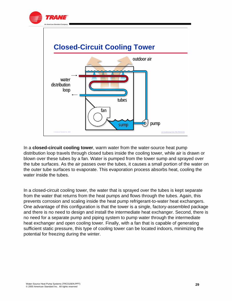
In a closed-circuit cooling tower, warm water from the water-source heat pump distribution loop travels through closed tubes inside the cooling tower, while air is drawn or blown over these tubes by a fan. Water is pumped from the tower sump and sprayed over the tube surfaces. As the air passes over the tubes, it causes a small portion of the water on the outer tube surfaces to evaporate. This evaporation process absorbs heat, cooling the water inside the tubes.
In a closed-circuit cooling tower, the water that is sprayed over the tubes is kept separate from the water that returns from the heat pumps and flows through the tubes. Again, this prevents corrosion and scaling inside the heat pump refrigerant-to-water heat exchangers.One advantage of this configuration is that the tower is a single, factory-assembled package and there is no need to design and install the intermediate heat exchanger. Second, there is no need for a separate pump and piping system to pump water through the intermediate heat exchanger and open cooling tower. Finally, with a fan that is capable of generating sufficient static pressure, this type of cooling tower can be located indoors, minimizing the potential for freezing during the winter.

30Water-Source Heat Pump Systems (TRC015EN.PPT)© 2000 American Standard Inc. All rights reserved
Air Conditioning Clinic TRG-TRC015-ENAir Conditioning Clinic TRG-TRC015-EN© American Standard Inc. 2000
Heat Adders
Boiler (electric, gas-fired)Heat exchangerNatural heat source (ground)
Heat AddersA heat adder is used to maintain the temperature of the water in the distribution loop above approximately 60ºF [16ºC]. The most common type of heat adder used in a water-source heat pump system is a hot-water boiler, operated either by electricity or a fossil fuel such as natural gas or heating oil.
Alternatively, buildings that contain separate hot-water systems or steam heating systems may use a heat exchanger to add heat to the water distribution loop. Again, this isolates the water in the distribution loop from the water in the other system.
Natural heat sources, such as the ground, will be discussed in Period Four.

31Water-Source Heat Pump Systems (TRC015EN.PPT)© 2000 American Standard Inc. All rights reserved
Air Conditioning Clinic TRG-TRC015-ENAir Conditioning Clinic TRG-TRC015-EN© American Standard Inc. 2000
Optional Storage Tank
pumpspumps
cooling towercooling tower
boilerboiler
heat pumpsheat pumps
hot waterhot waterstorage tankstorage tank
In many buildings, the temperature setpoint of the space thermostat is set back during unoccupied hours in the winter. For example, the space temperature is controlled to 68ºF [20ºC] during the day, but allowed to decrease to 60ºF [15.6ºC] overnight. This practice is called night setback. While it saves energy during unoccupied periods, night setbackimposes an additional heating load on the system when the set point is reset to 68ºF [20ºC] in the morning. This is called the morning warm-up load.
Because all heat pumps could start simultaneously when the set point is reset, the boiler must have sufficient capacity to provide heat to all the heat pumps. This could cause the boiler to have a larger capacity than needed during normal system operation. One way to reduce this required boiler capacity is to add a hot-water storage tank to the water distribution loop. When night setback is used, the boiler is operated for a short period of time to increase the temperature of the water in the loop and storage tank, to ensure that the morning warm-up load can be satisfied. Positioning this optional storage tank downstream of the heat pumps, and upstream of the boiler, allows the boiler to quickly add heat to the loop during normal operation.
Staggering the starting of heat pumps during morning warm-up using a system-level controller can eliminate the need for a storage tank in many applications.

32Water-Source Heat Pump Systems (TRC015EN.PPT)© 2000 American Standard Inc. All rights reserved
Air Conditioning Clinic TRG-TRC015-ENAir Conditioning Clinic TRG-TRC015-EN© American Standard Inc. 2000
Electric Heat
compressorcompressorfanfan
waterwaterlooploop
electricelectricstrip heaterstrip heater
An alternative to including a heat adder, such as a boiler, in the system is to install an electric strip heater either inside the heat pump or in the downstream ductwork. In this configuration, the heat pump operates in normal heating mode until the temperature of the water in the loop falls below approximately 60ºF [16ºC]. At that point, the compressor turns off and the electric strip heater is energized to warm the air.
Because several heat pumps in the system are likely to be operating in cooling mode, the loop temperature will begin to rise to a point where the electric strip heaters can be turned off and the heat pumps can return to operating in normal heating mode.
This alternative is commonly used in applications that are not expected to operate in the heating mode for much of the year, or in buildings where the tenant is billed directly for the electricity used to cool and heat only their space. A disadvantage of this alternative is that it increases the size and cost of electrical wiring to the heat pumps.

33Water-Source Heat Pump Systems (TRC015EN.PPT)© 2000 American Standard Inc. All rights reserved
Air Conditioning Clinic TRG-TRC015-ENAir Conditioning Clinic TRG-TRC015-EN© American Standard Inc. 2000
Air Distribution System
horizontalhorizontalheat pumpheat pump
supplysupplyductduct
returnreturnductduct
diffuserdiffuser
return airreturn airgrillegrille
Air Distribution SystemWater-source heat pump systems that use horizontal, vertical, rooftop, and sometimes vertical-stack configurations, typically include a supply-duct system to transport the air from the heat pump, through the diffusers, and into the space. A successful supply duct design achieves the following:
• Minimizes the static pressure and associated power requirements of the fan
• Limits the installed cost without sacrificing system efficiency
• Supplies the proper quantity of air to the space without excessive noise
• Accommodates space limitations without excessive pressure drop
• Minimizes design time
Figure 33 is an example of a horizontal water-source heat pump installed in the ceiling plenum above a space. These particular supply and return duct systems are designed to minimize the noise transmitted to the space. Acoustics is a primary consideration in the design and layout of any air distribution system. This issue will be discussed further in Period Six.
34Water-Source Heat Pump Systems (TRC015EN.PPT)© 2000 American Standard Inc. All rights reserved
Air Conditioning Clinic TRG-TRC015-ENAir Conditioning Clinic TRG-TRC015-EN© American Standard Inc. 2000
Dedicated Ventilation System
horizontalhorizontalheat pumpheat pump
air handlerair handler
ventilationventilationduct systemduct system
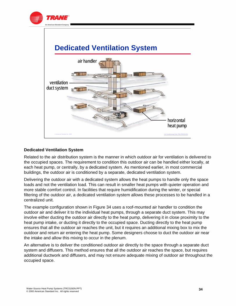
Dedicated Ventilation SystemRelated to the air distribution system is the manner in which outdoor air for ventilation is delivered to the occupied spaces. The requirement to condition this outdoor air can be handled either locally, at each heat pump, or centrally, by a dedicated system. As mentioned earlier, in most commercial buildings, the outdoor air is conditioned by a separate, dedicated ventilation system.
Delivering the outdoor air with a dedicated system allows the heat pumps to handle only the space loads and not the ventilation load. This can result in smaller heat pumps with quieter operation and more stable comfort control. In facilities that require humidification during the winter, or special filtering of the outdoor air, a dedicated ventilation system allows these processes to be handled in a centralized unit.
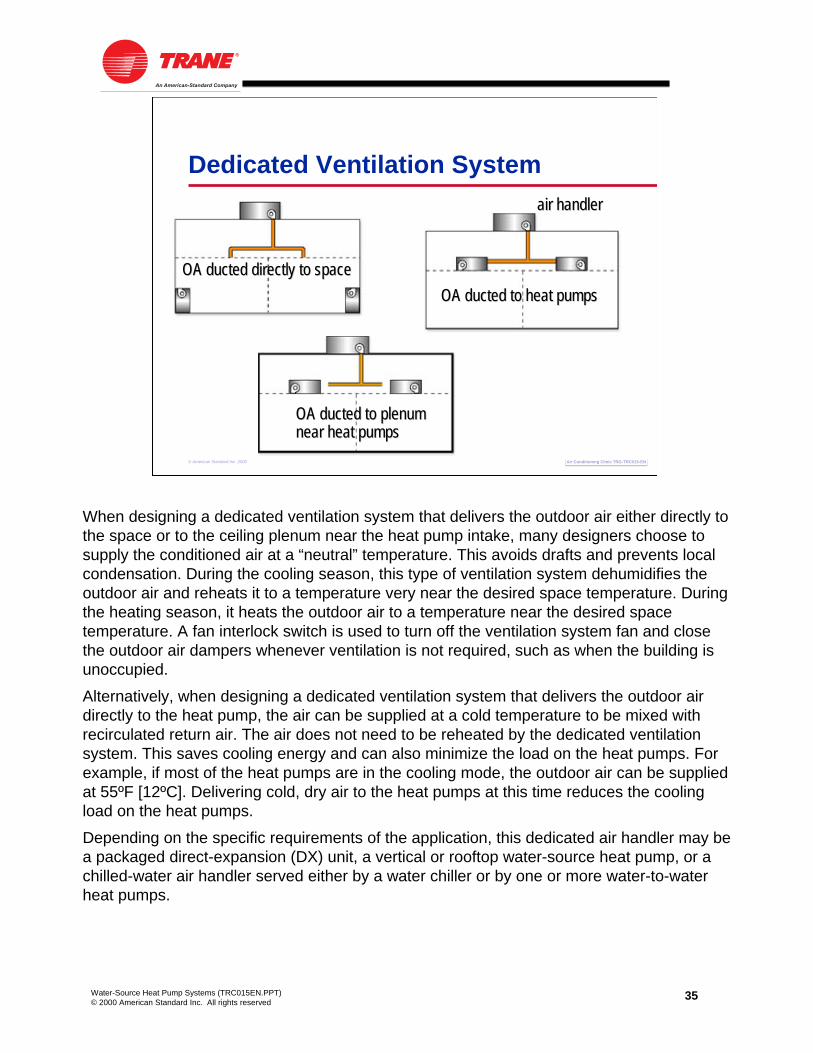
The example configuration shown in Figure 34 uses a roof-mounted air handler to condition the outdoor air and deliver it to the individual heat pumps, through a separate duct system. This may involve either ducting the outdoor air directly to the heat pump, delivering it in close proximity to the heat pump intake, or ducting it directly to the occupied space. Ducting directly to the heat pump ensures that all the outdoor air reaches the unit, but it requires an additional mixing box to mix the outdoor and return air entering the heat pump. Some designers choose to duct the outdoor air near the intake and allow this mixing to occur in the plenum.
An alternative is to deliver the conditioned outdoor air directly to the space through a separate duct system and diffusers. This method ensures that all the outdoor air reaches the space, but requires additional ductwork and diffusers, and may not ensure adequate mixing of outdoor air throughout the occupied space.
35Water-Source Heat Pump Systems (TRC015EN.PPT)© 2000 American Standard Inc. All rights reserved
Air Conditioning Clinic TRG-TRC015-ENAir Conditioning Clinic TRG-TRC015-EN© American Standard Inc. 2000
Dedicated Ventilation Systemair handlerair handler
OA ducted directly to spaceOA ducted directly to spaceOA ducted to heat pumpsOA ducted to heat pumps
OA ducted to plenumOA ducted to plenumnear heat pumpsnear heat pumps
When designing a dedicated ventilation system that delivers the outdoor air either directly to the space or to the ceiling plenum near the heat pump intake, many designers choose to supply the conditioned air at a “neutral” temperature. This avoids drafts and prevents local condensation. During the cooling season, this type of ventilation system dehumidifies the outdoor air and reheats it to a temperature very near the desired space temperature. During the heating season, it heats the outdoor air to a temperature near the desired space temperature. A fan interlock switch is used to turn off the ventilation system fan and close the outdoor air dampers whenever ventilation is not required, such as when the building is unoccupied.
Alternatively, when designing a dedicated ventilation system that delivers the outdoor air directly to the heat pump, the air can be supplied at a cold temperature to be mixed withrecirculated return air. The air does not need to be reheated by the dedicated ventilation system. This saves cooling energy and can also minimize the load on the heat pumps. For example, if most of the heat pumps are in the cooling mode, the outdoor air can be supplied at 55ºF [12ºC]. Delivering cold, dry air to the heat pumps at this time reduces the cooling load on the heat pumps.
Depending on the specific requirements of the application, this dedicated air handler may be a packaged direct-expansion (DX) unit, a vertical or rooftop water-source heat pump, or a chilled-water air handler served either by a water chiller or by one or more water-to-water heat pumps.

36Water-Source Heat Pump Systems (TRC015EN.PPT)© 2000 American Standard Inc. All rights reserved
Air Conditioning Clinic TRG-TRC015-ENAir Conditioning Clinic TRG-TRC015-EN© American Standard Inc. 2000
Exhaust-Air Heat Recovery
Coil loopsFixed-plate heat exchangersHeat pipesSensible- or total-energy wheels
totaltotal--energyenergywheelwheel
exhaustexhaustairair
outdooroutdoorairair
A centralized ventilation system makes it possible to implement exhaust-air heat recovery to precondition the outdoor air. In applications where the exhaust air from the building can be routed back to a central location, exhaust-air heat recovery is a very effective means of reducing the ventilation load and saving energy.
Coil loops, fixed-plate heat exchangers, heat pipes, and sensible- or total-energy wheels are all common devices used for transferring heat between the outdoor and exhaust air streams. This figure shows a total-energy wheel used to precondition the outdoor air. During the cooling season, this desiccant-coated wheel revolves slowly through the outdoor and exhaust air streams, removing both sensible heat and moisture from the outdoor air and rejecting it to the exhaust air. During the heating season, the wheel recovers both sensible heat and moisture from the exhaust air, and transfers it to the outdoor air.

37Water-Source Heat Pump Systems (TRC015EN.PPT)© 2000 American Standard Inc. All rights reserved
Air Conditioning Clinic TRG-TRC015-ENAir Conditioning Clinic TRG-TRC015-EN© American Standard Inc. 2000
System-Level Controlheatheatpumppump
thermostatthermostat
systemsystem--levellevelcontrollercontroller
System-Level ControlsAs mentioned earlier, each space is served by a dedicated heat pump that responds to the cooling and heating demands of the space. This is typically accomplished by using a conventional space thermostat to control each heat pump. The other pieces of equipment in the system, such as the cooling tower and boiler, also have dedicated controls.
A centralized control system can be used to monitor system operation and to coordinate all these pieces for optimized system control. At a minimum, a system-level controller should be used to operate the water circulation pumps, coordinate cooling tower and boiler operation to maintain the proper temperature in the water loop, and provide centralized monitoring of system operation.

38Water-Source Heat Pump Systems (TRC015EN.PPT)© 2000 American Standard Inc. All rights reserved
Air Conditioning Clinic TRG-TRC015-ENAir Conditioning Clinic TRG-TRC015-EN© American Standard Inc. 2000
Water-Loop Temperature Control
systemsystem--levellevelcontrollercontroller
cooling towercooling tower
pumpspumps
heat pumpsheat pumps
boilerboiler
As mentioned earlier, water-source heat pumps can run in either heating or cooling mode when the water loop temperature is maintained between 60ºF [16ºC] and 90ºF [32ºC]. Loop temperatures that are outside the recommended range can severely impact heat pump performance. For this reason, the primary function of a system-level controller is to monitor and maintain an acceptable temperature in the water loop.
The loop supply-water temperature sensor is typically located slightly downstream of the water circulating pumps. Additionally, a loop return-water temperature sensor is often located downstream of the heat pumps but upstream of the cooling tower. The system-level controller is then used to coordinate cooling tower and boiler operation, so that the temperature of the water that is supplied to the heat pumps is maintained within the acceptable range.
Further, communicating system-level controls offer the opportunity to optimize the water loop temperature, in an effort to minimize total-system energy consumption. For example, in the cooling mode, water-source heat pumps operate more efficiently with cooler water flowing through the refrigerant-to-water heat exchanger. However, making cooler water requires the cooling tower to use more energy. A smart, system-level control system can determine the optimum loop temperature that will minimize the combined energy consumed by the heat pumps and cooling tower.

39Water-Source Heat Pump Systems (TRC015EN.PPT)© 2000 American Standard Inc. All rights reserved
Air Conditioning Clinic TRG-TRC015-ENAir Conditioning Clinic TRG-TRC015-EN© American Standard Inc. 2000
Advanced System-Level Control
Centralized schedulingSchedule override Morning warm-up and cool-downAlarmsTrend loggingIntegration with other building systems
In addition to these basic functions, a system-level controller can be used to perform a number of other advanced functions that can further optimize system operation. These include:
• Centralized system scheduling and shutdown based on occupancy
• Schedule override to allow the system to operate when a space is occupied after scheduled hours
• Enabling morning warm-up and cool-down sequences
• Various alarms to indicate problems, required service, or needed maintenance
• Trend logging to help anticipate potential system problems
• Integration with the dedicated ventilation system, or other systems serving the building, such as lighting, security, and fire safety

40Water-Source Heat Pump Systems (TRC015EN.PPT)© 2000 American Standard Inc. All rights reserved
period fourSystem Configurations
© American Standard Inc. 2000
Water-Source Heat Pump Systems
Air Conditioning Clinic TRG-TRC015-ENAir Conditioning Clinic TRG-TRC015-EN
This period discusses various configurations of the water-source heat pump system, specifically introducing systems that use the earth as the heat rejecter and heat adder.

41Water-Source Heat Pump Systems (TRC015EN.PPT)© 2000 American Standard Inc. All rights reserved
Air Conditioning Clinic TRG-TRC015-ENAir Conditioning Clinic TRG-TRC015-EN© American Standard Inc. 2000
Cooling-Tower-and-Boiler System
boilerboiler
coolingcoolingtowertower
heat pumpsheat pumps
water pumpswater pumps
Cooling-Tower-and-Boiler SystemThe cooling-tower-and-boiler system is the system explained in Period Two. It uses a closed water loop to connect multiple water-source heat pumps. Typically, a hot-water boiler is employed to maintain closed-loop temperatures above 60ºF [16ºC], and a cooling tower is used to maintain closed-loop temperatures below 90ºF [32ºC]. All the heat pumps function independently, either by adding or removing heat from the common, closed water loop.
Because the excess heat from the building is rejected through a cooling tower, the system is more efficient than an air-cooled system. The cooling-tower-and-boiler system offers a low installation cost and is the most common application of water-source heat pumps.

42Water-Source Heat Pump Systems (TRC015EN.PPT)© 2000 American Standard Inc. All rights reserved
Air Conditioning Clinic TRG-TRC015-ENAir Conditioning Clinic TRG-TRC015-EN© American Standard Inc. 2000
Ground-Source Heat Pump Systems
groundgroundheat exchangerheat exchanger
Ground-Source Heat Pump SystemsA common variation of the water-source heat pump system uses the earth as the heat rejecter and heat adder. In general, these types of systems are referred to as ground-source heat pump systems. Ground-source systems take advantage of the earth’s relatively constant temperature, and use the ground or surface water as the heat rejecter and heat adder.
Ground-source heat pump systems don’t actually get rid of heat—they store it in the ground for use at a different time. During the summer, the heat pumps absorb heat from the building and store it in the ground. When the building requires heating, this stored heat can be recaptured from the ground. In a perfectly balanced system, the amount of heat stored over a given period of time would equal the amount of heat retrieved.
In a properly designed ground-source heat pump system, no cooling tower is necessary. From an architectural perspective, this allows all the heat from the building to be rejected without any visible sign of a cooling system. Also, if the heat pumps can satisfy all building heating requirements, no boiler is necessary, saving initial cost and floor space.
Ground-source heat pump systems offer the potential for operating-cost savings when compared to the traditional cooling-tower-and-boiler system. The installation costs associated with this system, however, must be considered in order to determine the economic viability. In general, the largest portion of the installation cost is due to the ground heat exchanger. Installation requires excavation, trenching, or boring, and in some areas there are very few qualified contractors for installing the ground heat exchanger.

43Water-Source Heat Pump Systems (TRC015EN.PPT)© 2000 American Standard Inc. All rights reserved
Air Conditioning Clinic TRG-TRC015-ENAir Conditioning Clinic TRG-TRC015-EN© American Standard Inc. 2000
Ground-Coupled System
heatheatpumpspumps
water pumpswater pumps
verticalvertical--loop groundloop groundheat exchangerheat exchanger
There are several types of ground-source systems. A ground-coupled system uses a closed system of special, high-density polyethylene pipes that are buried in the ground at a depth that takes advantage of the earth’s natural heat sink capabilities. When the building cooling load causes the temperature of the water loop to rise, heat is transferred from the water, flowing through the buried pipes, to the cooler earth. Conversely, when the temperature of the water loop begins to fall, the water flowing through the buried pipes absorbs heat from earth.
In a properly designed, ground-coupled system, operating and maintenance costs are low because a cooling tower and boiler are not required in the system. The pipes that make up the ground heat exchanger can be oriented in a vertical, horizontal, or spiral pattern. Any of these patterns can be designed to provide the same fluid temperatures under a given set of conditions. The choice depends on available land, soil conditions, and excavation costs.

44Water-Source Heat Pump Systems (TRC015EN.PPT)© 2000 American Standard Inc. All rights reserved
Air Conditioning Clinic TRG-TRC015-ENAir Conditioning Clinic TRG-TRC015-EN© American Standard Inc. 2000
Vertical Loop
AdvantagesRequires least amount of landLeast amount of total pipingCan require least amount of
pumping energy
DisadvantagesDrilling costs may be higher thantrenching costsBackfilling requires special material and practicesPotential for heat buildup
Vertical loops are the most common in commercial applications due to the limited land generally available. Vertical bore holes are drilled to depths of 200 to 500 ft [60 to 150 m], with a diameter of 4 to 8 in [10 to 20 cm] each. Installation requires the knowledge and availability of a certified loop contractor with proper drilling equipment.
Advantages of vertical loops include:
• They require the least amount of land of the three patterns. Vertical loops require anywhere from 60 to 275 ft2 of ground surface per cooling ton [1.6 to 7.3 m2/kW].
• They typically require less total piping than the other two configurations because the ground temperature is more constant at greater depths.
• When piped in a parallel reverse-return configuration, this pattern requires the least amount of pumping energy of the three.
Disadvantages include:
• Drilling costs are frequently higher than the trenching costs associated with horizontal and spiral loops.
• Backfilling of the bore holes requires special attention to fill material and to ensure that the pipes and earth remain in contact.
• If the bore holes are spaced too close together, there is a potential for long-term heat build-up in the ground that may be undesirable.

45Water-Source Heat Pump Systems (TRC015EN.PPT)© 2000 American Standard Inc. All rights reserved
Air Conditioning Clinic TRG-TRC015-ENAir Conditioning Clinic TRG-TRC015-EN© American Standard Inc. 2000
Horizontal Loop
AdvantagesTrenching costs are lower than
drilling costsMay not build up as much heat
over time
DisadvantagesRequires more land than vertical loopsGreater ground-temperature variationsMore total piping than vertical loopsRisk of pipe damage during backfilling of trenches
Horizontal loops are often considered when adequate land is available. Historically, horizontal loops consisted of a single layer of pipe buried in the ground using a trencher. However, land requirements have been reduced with the advent of multiple-layer horizontal loops. While less land and trenching is required, more total length of piping is required compared to a single layer loop. The pipes are placed in trenches, typically 6 ft [1.8 m] deep and spaced 6 to 15 ft [1.8 to 4.6 m] apart. Trench length can range from 100 to 400 ft per cooling ton [8.7 to 34.7 m/kW].
Advantages of horizontal loops:
• Trenching costs are typically lower than the drilling costs associated with vertical loop installation.
• They may not build up as much heat over time because the pipes are closer to the surface, where heat can be dissipated to the atmosphere. This may also make it a good application for melting ice in parking lots.
Disadvantages:
• Horizontal loops require a larger area of land for an effective heat exchanger.
• At this shallower depth, ground temperatures are subject to seasonal temperature variations, rainfall, and snow melting. Obtaining the same system efficiency as the vertical loop requires a more complicated design with longer pipe lengths.
• The longer pipe lengths also require more antifreeze solution, when necessary.
• The pipe is at greater risk of damage during backfilling of the trenches.

46Water-Source Heat Pump Systems (TRC015EN.PPT)© 2000 American Standard Inc. All rights reserved
Air Conditioning Clinic TRG-TRC015-ENAir Conditioning Clinic TRG-TRC015-EN© American Standard Inc. 2000
Spiral Loop
AdvantagesRequires less land area and trenching than horizontal loopsLower installation cost compared to horizontal loops
DisadvantagesRequires more total piping than vertical and horizontal loopsStill requires a large area of land
A variation of the multiple-layer, horizontal loop is the spiral loop. The spiral loop includes an unraveled roll of pipe placed either vertically in a trench or horizontally in an open pit. The spiral loop generally requires more total piping, typically 500 to 1,000 ft per cooling ton [43 to 86 m/kW], but less trenching than multiple-layer, horizontal loops. Both horizontal and spiral loop systems are generally associated with small commercial and residential applications where land requirements are less of a factor.
In addition to the advantages already listed for horizontal loops, advantages of spiral loops include:
• Less land area and trenching than traditional horizontal loops.
• Lower installation costs than traditional horizontal loops.
Disadvantages:
• Spiral loops require more total length of piping than vertical or horizontal loops.
• A relatively large area of land is still required.

47Water-Source Heat Pump Systems (TRC015EN.PPT)© 2000 American Standard Inc. All rights reserved
Air Conditioning Clinic TRG-TRC015-ENAir Conditioning Clinic TRG-TRC015-EN© American Standard Inc. 2000
Surface-Water System
heatheatpumpspumps
water pumpswater pumps
groundgroundheat exchangerheat exchanger
lakelake
Where local building codes require water-retention ponds for short-term storage of surface run-off, a surface-water heat pump system can be very cost effective. In the correct cooling-dominated application, a moderately-sized pond or lake can provide enough heat rejection and heat addition to maintain proper temperatures in the water loop, without the need for a cooling tower and boiler. Surface-water systems typically use a series of closed loops of piping, similar to the spiral loop pattern. The pipes are submerged 6 to 8 ft [2 to 2.5 m] deep (preferably deeper) in a pond or lake and secured to concrete anchors so they float 9 to 18 in [23 to 46 cm] above the bottom. Typical installations require around 300 to 500 ft of pipe per cooling ton [27 to 45 m/kW] and approximately 3,000 ft2 of surface water per cooling ton [79 m2/kW].
This type of system will probably experience greater temperature variations in the loop than the ground-coupled system. The lower installation cost, however, may compensate for the reduction in heat-pump efficiency.
48Water-Source Heat Pump Systems (TRC015EN.PPT)© 2000 American Standard Inc. All rights reserved
Air Conditioning Clinic TRG-TRC015-ENAir Conditioning Clinic TRG-TRC015-EN© American Standard Inc. 2000
Ground-Water System
heatheatpumpspumps
water pumpswater pumps
wellwell
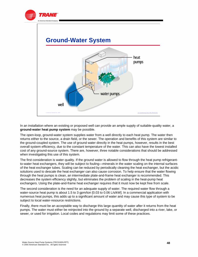
In an installation where an existing or proposed well can provide an ample supply of suitable-quality water, a ground-water heat pump system may be possible.
The open-loop, ground-water system supplies water from a well directly to each heat pump. The water then returns either to the source, a drain field, or the sewer. The operation and benefits of this system are similar to the ground-coupled system. The use of ground water directly in the heat pumps, however, results in the best overall system efficiency, due to the constant temperature of the water. This can also have the lowest installed cost of any ground-source system. There are, however, three notable considerations that should be addressed when investigating this use of this system.
The first consideration is water quality. If the ground water is allowed to flow through the heat pump refrigerant-to-water heat exchangers, they will be subject to fouling—minerals in the water scaling on the internal surfaces of the heat exchanger tubes. Scaling can be reduced by periodically cleaning the heat exchanger, but the acidic solutions used to descale the heat exchanger can also cause corrosion. To help ensure that the water flowing through the heat pumps is clean, an intermediate plate-and-frame heat exchanger is recommended. This decreases the system efficiency slightly, but eliminates the problem of scaling in the heat-pump heat exchangers. Using the plate-and-frame heat exchanger requires that it must now be kept free from scale.
The second consideration is the need for an adequate supply of water. The required water flow through a water-source heat pump is about 1.5 to 3 gpm/ton [0.03 to 0.06 L/s/kW]. In a commercial application with numerous heat pumps, this adds up to a significant amount of water and may cause this type of system to be subject to local water-resource restrictions.
Finally, there must be an acceptable way to discharge this large quantity of water after it returns from the heat pumps. The water must either be reinjected into the ground by a separate well, discharged into a river, lake, or sewer, or used for irrigation. Local codes and regulations may limit some of these practices.

49Water-Source Heat Pump Systems (TRC015EN.PPT)© 2000 American Standard Inc. All rights reserved
Air Conditioning Clinic TRG-TRC015-ENAir Conditioning Clinic TRG-TRC015-EN© American Standard Inc. 2000
Hybrid WSHP Systems
pumpspumpscooling towercooling tower
boilerboiler
heat pumpsheat pumpsair handlerair handler
water chillerwater chiller
Hybrid SystemsSome designers view the water-source heat pump system solely as an alternative to other types of HVAC systems. Hybrid systems composed of water-source heat pumps and other types of HVAC equipment, however, may be well-suited to meet the specific requirements of a building. While there are many possible combinations, two such systems are included here as examples.
In some applications, the large quantity or extreme condition of outdoor air brought into the building for ventilation may lead to the selection of a chilled-water air handler to cool and dehumidify the outdoor air. The first example hybrid system, shown in Figure 49, uses a dedicated, water-cooled chiller serving a chilled-water coil in an air handler. Notice that instead of using a separate cooling tower, the chiller condenser is connected to the same water distribution loop that is used by the water-source heat pump system. In the late spring and early fall, some of the heat pumps operate in the heating mode but the outdoor air still needs to be cooled and dehumidified. The heat rejected by the chiller condenser into the water loop can be used to provide heat for the spaces that require heating.
In the summer, the common cooling tower is used to reject the heat from the heat pumps as well as the chiller. While the capacity of this tower may have to be increased, it will probably reduce the overall space required by eliminating the second tower.

50Water-Source Heat Pump Systems (TRC015EN.PPT)© 2000 American Standard Inc. All rights reserved
Air Conditioning Clinic TRG-TRC015-ENAir Conditioning Clinic TRG-TRC015-EN© American Standard Inc. 2000
Hybrid WSHP Systems
selfself--contained VAVcontained VAVair conditionerair conditioner
pumpspumpscooling towercooling tower
boilerboiler
heat pumpsheat pumps
to interiorto interiorspacesspaces
This second example hybrid system, shown in Figure 50, uses variable-air-volume (VAV),self-contained air conditioners to serve the interior spaces of the building and water-source heat pumps to serve the perimeter spaces. The interior spaces in this example have variable loads, but always require cooling.
These water-cooled, self-contained air conditioners include a complete refrigeration circuit and a VAV supply fan that varies the airflow supplied to the interior spaces, resulting in part-load energy savings. Heat is rejected from the self-contained units into the common water loop, where it can be absorbed by the heat pumps that are providing heat to the perimeter spaces.

51Water-Source Heat Pump Systems (TRC015EN.PPT)© 2000 American Standard Inc. All rights reserved
period fiveMaintenance Considerations
© American Standard Inc. 2000
Water-Source Heat Pump Systems
Air Conditioning Clinic TRG-TRC015-ENAir Conditioning Clinic TRG-TRC015-EN
While the manufacturer should be consulted for specific equipment maintenance requirements, the intent of this period is to discuss some of the general maintenance requirements of water-source heat pump systems.
52Water-Source Heat Pump Systems (TRC015EN.PPT)© 2000 American Standard Inc. All rights reserved
Air Conditioning Clinic TRG-TRC015-ENAir Conditioning Clinic TRG-TRC015-EN© American Standard Inc. 2000
Water-Source Heat Pumps
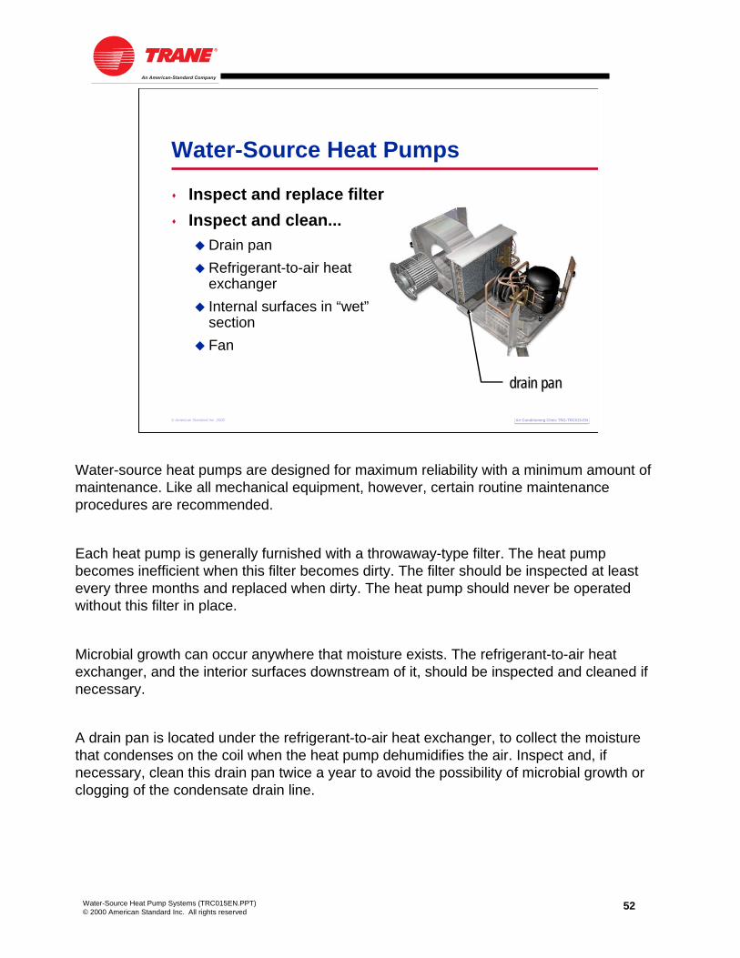
Inspect and replace filterInspect and clean...
Drain panRefrigerant-to-air heat exchangerInternal surfaces in “wet”sectionFan
drain pandrain pandrain pan
Water-source heat pumps are designed for maximum reliability with a minimum amount of maintenance. Like all mechanical equipment, however, certain routine maintenance procedures are recommended.
Each heat pump is generally furnished with a throwaway-type filter. The heat pump becomes inefficient when this filter becomes dirty. The filter should be inspected at least every three months and replaced when dirty. The heat pump should never be operated without this filter in place.
Microbial growth can occur anywhere that moisture exists. The refrigerant-to-air heat exchanger, and the interior surfaces downstream of it, should be inspected and cleaned if necessary.
A drain pan is located under the refrigerant-to-air heat exchanger, to collect the moisture that condenses on the coil when the heat pump dehumidifies the air. Inspect and, if necessary, clean this drain pan twice a year to avoid the possibility of microbial growth or clogging of the condensate drain line.

53Water-Source Heat Pump Systems (TRC015EN.PPT)© 2000 American Standard Inc. All rights reserved
Air Conditioning Clinic TRG-TRC015-ENAir Conditioning Clinic TRG-TRC015-EN© American Standard Inc. 2000
Water Distribution Loop
Recommended maintenanceClean strainers in open systemsCheck cleanliness of refrigerant-to-water heat exchangersUse a qualified water-treatment specialist for cooling tower maintenanceCheck loop water for proper amount of antifreeze, when necessary
To ensure optimum performance, heat transfer surfaces must be kept free of scale. Even a thin deposit of scale can substantially reduce heat-transfer capacity. For water-source heat pump systems that use well water, or an open cooling tower without an intermediate heat exchanger, a strainer is recommended to keep debris from entering the system. This strainer should be cleaned at least once a year. It is also important to check the cleanliness of the heat pump’s refrigerant-to-water heat exchanger periodically. Should it become dirty or scaled as a result of bad-quality water, the heat exchanger should be back-flushed and chemically cleaned to remove the scale.
Additionally, in systems with a cooling tower, engage the services of a qualified water treatment specialist to determine the level of water treatment required to remove contaminants from the cooling tower water. Finally, it is good practice to periodically test the loop water to verify that it contains the proper amount of antifreeze, when necessary.
With regard to the cooling tower and boiler, strictly follow the maintenance requirements and recommendations published by the manufacturer.

54Water-Source Heat Pump Systems (TRC015EN.PPT)© 2000 American Standard Inc. All rights reserved
Air Conditioning Clinic TRG-TRC015-ENAir Conditioning Clinic TRG-TRC015-EN© American Standard Inc. 2000
Freeze Protection
Closed-circuit cooling towerLocate indoorsUse antifreeze solutionWinterize the tower
Open cooling towerLocate intermediate heat exchanger indoorsWinterize the tower
Ground-coupled systemsUse antifreeze solution closed-circuit cooling towerclosedclosed--circuit cooling towercircuit cooling tower
Because the water loop operates all year long, freeze protection during the winter months is important in a water-source heat pump system. In a cooling-tower-and-boiler system, freeze protection depends on the type of cooling tower used. If a closed-circuit cooling tower is used, freeze protection is typically provided by:
• Locating the cooling tower indoors
This technique uses dampers to close off the tower from cold outdoor air. The dampers and ductwork associated with this option adds to the initial cost of the system, but, where possible, it is probably the best method of freeze protection for closed-circuit towers.
• Using an antifreeze solution
This is probably the simplest method of freeze protection. It involves adding a certain percentage of antifreeze to the water in the closed loop. While this provides protection from freezing, it degrades the efficiency and capacity of the heat pumps, requires more pump energy, and requires additives to prevent corrosion.
• Winterizing the cooling tower
This involves adding insulation, a discharge damper, and a sump heater to the tower, and adding insulation and heat tape to all exposed water piping. Some designers prefer to drain the tower sump during the winter.
If an open cooling tower is used, the intermediate heat exchanger should be located indoors, eliminating the need to protect the closed water loop from freezing. The tower sump is the only component that must be protected. This can be accomplished using the the methods listed above for winterizing the cooling tower.
Ground-coupled heat pump systems can also experience temperatures below freezing. These systems are generally protected by adding antifreeze to the loop water.

55Water-Source Heat Pump Systems (TRC015EN.PPT)© 2000 American Standard Inc. All rights reserved
period sixApplication Considerations
© American Standard Inc. 2000
Water-Source Heat Pump Systems
Air Conditioning Clinic TRG-TRC015-ENAir Conditioning Clinic TRG-TRC015-EN
Several considerations must be addressed when using water-source heat pump systems. The issue of delivering outdoor air for ventilation was previously discussed in Period Three. Additional issues to be discussed in this period include:
• Acoustics
• Space humidity control
• Condensate management
• Airside and waterside economizers
• Building pressurization
• Equipment rating standards
While not all-inclusive, this list does represent some of the key issues to consider when using this type of system.

56Water-Source Heat Pump Systems (TRC015EN.PPT)© 2000 American Standard Inc. All rights reserved
Air Conditioning Clinic TRG-TRC015-ENAir Conditioning Clinic TRG-TRC015-EN© American Standard Inc. 2000
Acoustic Considerations
consoleWSHP
consoleconsoleWSHPWSHP
horizontalWSHP
horizontalhorizontalWSHPWSHP
supplysupplysupply
returnreturnreturn
hallwayhallwayhallwayspacespacespace
AcousticsA water-source heat pump is typically located in, or very close to, the occupied space. Because a heat pump includes both a fan and compressor, proper acoustics should be considered during the design phase of a project. Most of the problems associated with equipment-generated sound can be avoided by properly selecting and locating the components of the HVAC system. Additionally, acoustic modeling can be used to predict space acoustic performance and determine the lowest-cost design to meet specific noise requirements. There are, however, some general recommendations for designing water-source heat pumps for proper acoustics.
As mentioned, proper location of the equipment is possibly the best method of obtaining acceptable sound levels. For horizontal heat pumps installed in the plenum above the ceiling, locate them above a noncritical space such as a hallway or bathroom. For vertical heat pumps installed in a closet, locate the closet adjacent to a noncritical space. Locate rooftop heat pumps above a hallway, bathroom, storage, or other noncritical space.
When using heat pumps that will be installed directly in the occupied space, such as a console, unit ventilator, or vertical-stack heat pump, locate the unit against a single vertical surface (wall) so that the sound radiates in a uniform pattern. Avoid locating the unit immediately adjacent to two or three vertical reflecting surfaces. Also, install the heat pump so that the sound radiates away from the acoustically-sensitive areas of the space.

57Water-Source Heat Pump Systems (TRC015EN.PPT)© 2000 American Standard Inc. All rights reserved
Air Conditioning Clinic TRG-TRC015-ENAir Conditioning Clinic TRG-TRC015-EN© American Standard Inc. 2000
Acoustic Considerations
supplysupplyductduct
returnreturnductduct
diffuserdiffuser
horizontalhorizontalheat pumpheat pump
return airreturn airgrillegrille
For heat pump configurations that use ductwork to deliver air to the space, such as horizontal, vertical, rooftop, and some vertical-stack heat pumps, the design of the supply-and return-air distribution systems is critical for ensuring proper space acoustics. The example system shown in Figure 57 includes the following features that help reduce the amount of noise that reaches the occupied space.
• The supply duct system has two or more 90-degree turns.
• At least the first 5 ft [1.5 m] of supply duct is lined.
• The first duct takeoff is at least two to three duct diameters downstream from the fan discharge.
• Multiple diffusers deliver air to the space.
• The air velocity in the duct is kept low.
• Flexible duct, pipe, and electrical connections isolate vibrations.
Noise control applies to the return side of the air distribution system as well as to the supply side. This example uses a return duct system. It includes two or more 90-degree bends prior to the intake of the heat pump, and again, air velocity in the return duct is kept low.

58Water-Source Heat Pump Systems (TRC015EN.PPT)© 2000 American Standard Inc. All rights reserved
Air Conditioning Clinic TRG-TRC015-ENAir Conditioning Clinic TRG-TRC015-EN© American Standard Inc. 2000
Acoustic Considerations
verticalWSHPverticalverticalWSHPWSHP return
airreturnreturnairair
supply airsupply airsupply air
closetclosetcloset
returnairduct
returnreturnairairductduct
Unless the return air path is through the plenum, a vertical heat pump installed in a closet will typically use a louver in the closet door as the return air path. In this configuration it is critical to prevent direct, line-of-sight sound transmission to the space. This can often be best prevented by attaching a short return-air duct to the louver, making a 90-degree turn, and extending the duct up near the ceiling of the closet. The design and construction of the wall that separates the occupied space from the heat pump are also crucial.
These general recommendations may or may not improve the acoustic performance of a specific installation. An acoustic analysis that considers the specifics of each project should be conducted to determine the lowest-cost design that meets the project requirements.

59Water-Source Heat Pump Systems (TRC015EN.PPT)© 2000 American Standard Inc. All rights reserved
Air Conditioning Clinic TRG-TRC015-ENAir Conditioning Clinic TRG-TRC015-EN© American Standard Inc. 2000
Space Humidity Control
00 1010 2020 3030 4040 5050 6060 7070 8080 9090 100100relative humidity (%)relative humidity (%)
ASHRAEASHRAE--recommendedrecommended
discomfort & discomfort & health problemshealth problems
microbial growthmicrobial growth
source: Section 5.10 of ASHRAE Standard 62–1999source: Section 5.10 of ASHRAE Standard 62–1999
Space Humidity ControlHigh levels of indoor moisture can cause a variety of problems for the building structure and furnishings, and can affect the health of building occupants. Indoor moisture may be in the form of standing water or sustained, high relative humidity levels. While high relative humidity in a space impacts occupant comfort and productivity, it can also result in the growth of mold and other microorganisms that can seriously affect human health.
In addition to health issues, mold can also prematurely deteriorate building furnishings and even the structure itself. Common areas affected include the underside of wall coverings, ceiling tiles, and carpets. Due to these potential problems, ASHRAE Standard 62–1999, Ventilation for Acceptable Indoor Air Quality, recommends that relative humidity in a space be maintained between 30 percent and 60 percent.
Because a water-source heat pump delivers a constant volume of air to the space, it can be susceptible to high relative humidity levels in a space at part-load conditions. A dedicated ventilation system that removes moisture from the outdoor air can help minimize this problem, but it does not necessarily eliminate the concern.
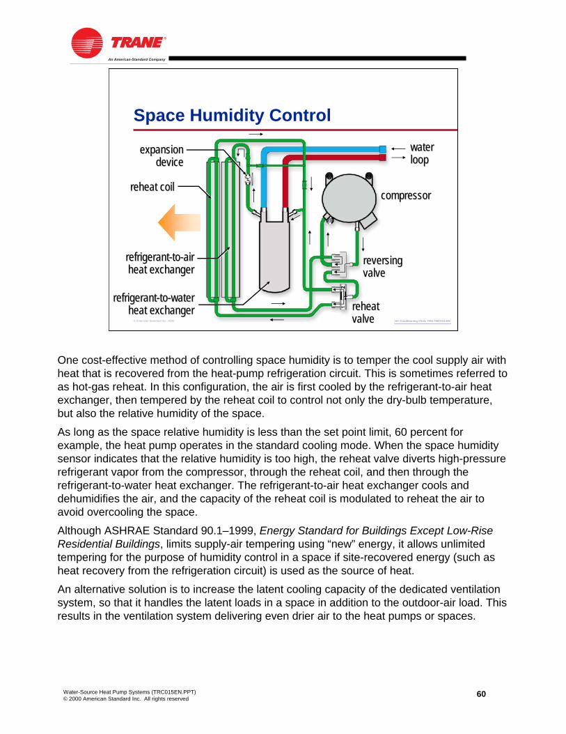
60Water-Source Heat Pump Systems (TRC015EN.PPT)© 2000 American Standard Inc. All rights reserved
Air Conditioning Clinic TRG-TRC015-ENAir Conditioning Clinic TRG-TRC015-EN© American Standard Inc. 2000
Space Humidity Control
compressorcompressor
refrigerantrefrigerant--toto--airairheat exchangerheat exchanger
reversingreversingvalvevalve
expansionexpansiondevicedevice
refrigerantrefrigerant--toto--waterwaterheat exchangerheat exchanger
waterwaterlooploop
reheat coilreheat coil
reheatreheatvalvevalve
One cost-effective method of controlling space humidity is to temper the cool supply air with heat that is recovered from the heat-pump refrigeration circuit. This is sometimes referred to as hot-gas reheat. In this configuration, the air is first cooled by the refrigerant-to-air heat exchanger, then tempered by the reheat coil to control not only the dry-bulb temperature, but also the relative humidity of the space.
As long as the space relative humidity is less than the set point limit, 60 percent for example, the heat pump operates in the standard cooling mode. When the space humidity sensor indicates that the relative humidity is too high, the reheat valve diverts high-pressure refrigerant vapor from the compressor, through the reheat coil, and then through the refrigerant-to-water heat exchanger. The refrigerant-to-air heat exchanger cools and dehumidifies the air, and the capacity of the reheat coil is modulated to reheat the air to avoid overcooling the space.
Although ASHRAE Standard 90.1–1999, Energy Standard for Buildings Except Low-Rise Residential Buildings, limits supply-air tempering using “new” energy, it allows unlimited tempering for the purpose of humidity control in a space if site-recovered energy (such as heat recovery from the refrigeration circuit) is used as the source of heat.
An alternative solution is to increase the latent cooling capacity of the dedicated ventilation system, so that it handles the latent loads in a space in addition to the outdoor-air load. This results in the ventilation system delivering even drier air to the heat pumps or spaces.

61Water-Source Heat Pump Systems (TRC015EN.PPT)© 2000 American Standard Inc. All rights reserved
Air Conditioning Clinic TRG-TRC015-ENAir Conditioning Clinic TRG-TRC015-EN© American Standard Inc. 2000
Condensate Management
condensatecondensatedrain pandrain pan
refrigerantrefrigerant--toto--airairheat exchangerheat exchanger
fanfan
Condensate ManagementWhen a water-source heat pump cools and dehumidifies the air passing through the refrigerant-to-air heat exchanger, moisture condenses if the surface temperature is lower than the dew point of the entering air. To collect this condensate, the heat pump contains a drain pan that is positioned under the heat exchanger. A drainage system must be designed to dispose of this condensate properly.

62Water-Source Heat Pump Systems (TRC015EN.PPT)© 2000 American Standard Inc. All rights reserved
Air Conditioning Clinic TRG-TRC015-ENAir Conditioning Clinic TRG-TRC015-EN© American Standard Inc. 2000
Condensate Management
drawdraw--throughthroughheat pumpheat pump
fanfansupplysupplyductduct
ventvent
condensatecondensatedrain linedrain line
traptrap
returnreturnairair
If the heat pump has a draw-through configuration, a vented trap must be installed in the drain line from each heat pump. Under normal conditions, condensate runs down the fins and drips into the drain pan. If no trap is installed, no water seal is created in the drain line, and the negative pressure created by the draw-through fan causes air to be drawn back in from the drain line. This incoming air stream could launch water droplets into the air, allowing the fan to propel this moisture into other parts of the system. These water droplets, like an aerosol mist, can be carried through the ducts and even into the occupied space, increasing the risk of microbial growth. Furthermore, condensate drain lines typically flow into the building waste or sewage lines, creating the potential to introduce contaminants and odors from the sewage system into the air stream.
In a properly trapped system, as shown in Figure 62, when condensate forms during normal operation, the water level in the trap rises to balance the negative pressure inside the unit and creates a seal. This allows the condensate to flow through the drain line.
While a heat pump with a blow-through configuration still requires a condensate drain line, it does not require a trap and vent to ensure proper condensate flow.
As mentioned earlier, the drain pan should be inspected and cleaned to avoid the possibility of the drain line clogging and overflowing the drain pan.

63Water-Source Heat Pump Systems (TRC015EN.PPT)© 2000 American Standard Inc. All rights reserved
Air Conditioning Clinic TRG-TRC015-ENAir Conditioning Clinic TRG-TRC015-EN© American Standard Inc. 2000
Airside Economizerreturnreturn
airairsupplysupplyairair
outdooroutdoorairair
verticalWSHPverticalverticalWSHPWSHP
EconomizersThe energy consumed by a water-source heat pump system can often be reduced through the use of an airside or waterside economizer. Additionally, ASHRAE Standard 90.1–1999 requires the use of an economizer in certain climates, depending on the size of the system.
An airside economizer is probably the most well-known type of economizer and is most commonly used with large vertical, rooftop, and unit-ventilator heat pumps. Rooftop and unit-ventilator (which are typically installed along a perimeter wall) heat pumps require no ductwork for outdoor air. Large vertical heat pumps have the capcity to serve a larger area, which can help offset the added cost of the larger ductwork necessary to deliver full airflow to the heat pumps during the economizer cycle.
The airside economizer should be disengaged, however, when the temperature of the water loop drops too far, below 65ºF [18.3ºC] for example. Otherwise, the heat pumps that are operating in heating mode, to serve the perimeter spaces, may lower the loop temperature to the point where the boiler must turn on. Without the heat being rejected from the interior heat pumps, the cost of operating the boiler may exceed the savings from turning off the interior heat pumps.

64Water-Source Heat Pump Systems (TRC015EN.PPT)© 2000 American Standard Inc. All rights reserved
Air Conditioning Clinic TRG-TRC015-ENAir Conditioning Clinic TRG-TRC015-EN© American Standard Inc. 2000
Waterside Economizer
horizontalhorizontalheat pumpheat pump
refrigerantrefrigerant--toto--waterwaterheat exchangerheat exchanger
watersidewatersideeconomizer coileconomizer coil threethree--wayway
valvevalve
Alternatively, a waterside economizer can provide an inexpensive means of free cooling when used in building systems that require perimeter heating and interior cooling. In the winter months, the perimeter heat pumps extract heat from the water loop, lowering the water temperature. The interior spaces still require cooling because of heat generated by lights, people, and office equipment. The cooler loop water circulated through a water-source heat pump serving an interior space can provide free cooling without operating the heat pump compressor.
In this example, a temperature sensor and three-way valve divert the cool loop water through the waterside economizer coil to cool the entering air, and then on to the refrigerant-to-water heat exchanger. The three-way valve allows the economizer coil to be bypassed when not in use, saving pump energy, and also allows the economizer to supplement the normal cooling cycle, if possible.
The waterside economizer can also satisfy code requirements for an economizer cycle.

65Water-Source Heat Pump Systems (TRC015EN.PPT)© 2000 American Standard Inc. All rights reserved
Air Conditioning Clinic TRG-TRC015-ENAir Conditioning Clinic TRG-TRC015-EN© American Standard Inc. 2000
Building Pressurization
infiltrationinfiltration
Building PressurizationEffective building- and space-pressure control not only ensures proper distribution of conditioned and ventilation air to the space, but can also confine odors and contaminants to specific areas of the building.
The pressure difference between the indoors and outdoors is controlled by adjusting the quantity of air supplied to, and removed from, the building. If more air is supplied to the building than is exhausted, the building is overpressurized. Overpressurization hinders proper air distribution, leads to loss of temperature control, and causes doors to stand open.
Similarly, if less air is supplied to the building than is exhausted, the building isunderpressurized. Underpressurization results in hard-to-open doors, drafts, and infiltration of unconditioned outdoor air. Infiltration not only impacts thermal comfort, but infiltration of humid outdoor air can also lead to microbial growth and associated indoor air quality (IAQ) problems.

66Water-Source Heat Pump Systems (TRC015EN.PPT)© 2000 American Standard Inc. All rights reserved
Air Conditioning Clinic TRG-TRC015-ENAir Conditioning Clinic TRG-TRC015-EN© American Standard Inc. 2000
Building Pressurization
horizontalhorizontalheat pumpheat pump
air handlerair handler
ventilationventilationduct systemduct system
central relief fancentral relief fan
In addition to providing conditioned outdoor air for ventilation, a dedicated ventilation system is used to make up for the air that is exhausted locally from the certain areas of the building, such as bathrooms, kitchens, and lab spaces. Because water-source heat pumps deliver a constant volume of air to the spaces they serve, and because most systems with a dedicated ventilation system do not use an airside economizer cycle, maintaining proper building pressurization during occupied periods is generally not very complex. Even in a properly balanced system, however, the wind, variable operation of local exhaust fans, and “stack effect” in taller buildings, can result in pressure fluctuations. Direct control of building pressure may be desired. This commonly involves controlling the capacity of a central relief fan to maintain a desired static-pressure difference between indoors and outdoors, usually a slightly positive building pressure.
Control of building pressure during unoccupied periods, however, can be complex. In most applications, the dedicated ventilation system is turned off during unoccupied periods. In some cases, however, local exhaust fans are allowed to operate, either by design or as an oversight. Because air is still being exhausted from the building, but no air is being brought in by the ventilation system, a negative pressure is created in the building with respect to the outdoors. This results in the infiltration of unconditioned outdoor air. In some climates, this can result in an unacceptably-high relative humidity, increasing the risk of microbial growth and associated IAQ problems
One solution is to design a building control system that turns off all local exhaust fans whenever the ventilation system is not operating. However, this may require a manual override to allow for after hours cleaning processes. Another solution is to monitor the building relative humidity, and operate either the heat pumps or the central ventilation system to dehumidify the building whenever the relative humidity rises to an unacceptable level.

67Water-Source Heat Pump Systems (TRC015EN.PPT)© 2000 American Standard Inc. All rights reserved
Air Conditioning Clinic TRG-TRC015-ENAir Conditioning Clinic TRG-TRC015-EN© American Standard Inc. 2000
Equipment Rating Standards
PurposeEstablish definitions, testing, and rating requirements
ScopeWater-source heat pumpsCooling only, heating only, or both functionsWater-source and ground-source system applications
Equipment Rating StandardsThe Air Conditioning & Refrigeration Institute (ARI) establishes rating standards for packaged HVAC equipment. The International Organization for Standardization (ISO) facilitates the international coordination and unification of standards. The overall objective of ARI/ISO Standard 13256–1 is to promote the consistent rating of various types and sizes of packaged heat pumps. It covers heating and cooling equipment referred to as water-source heat pumps. The equipment may provide cooling only, heating only, or both functions, and is typically designed for use within one or more of the following applications:
• Water-loop heat pump system
This system uses water-source heat pumps with liquid circulating in a common piping loop that functions as a heat source/heat sink. The temperature of the liquid loop is usually mechanically controlled, like the cooling-tower-and-boiler system discussed in this clinic.
• Ground-water heat pump system
This system uses water-source heat pumps with water pumped from a well, lake, or stream that functions as a heat source/heat sink. The temperature of the water loop is related to the climatic conditions. This is like the ground-water system discussed in this clinic.
• Ground-loop heat pump system
This system uses water-source heat pumps with a brine solution circulating through a subsurface piping loop that functions as a heat source/heat sink. The heat-exchange loop may be placed in horizontal trenches or vertical bores, or be submerged in a body of surface water, such as a lake. The temperature of the brine in the loop is related to the climatic conditions. This is like the ground-coupled and surface-water systems discussed in this clinic.
These three applications were previously covered separately by ARI Standards 320, 325 and 330.

68Water-Source Heat Pump Systems (TRC015EN.PPT)© 2000 American Standard Inc. All rights reserved
period sevenReview
© American Standard Inc. 2000
Water-Source Heat Pump Systems
Air Conditioning Clinic TRG-TRC015-ENAir Conditioning Clinic TRG-TRC015-EN
We will now review the main concepts that were covered in this clinic on water-source heat pump systems.

69Water-Source Heat Pump Systems (TRC015EN.PPT)© 2000 American Standard Inc. All rights reserved
Air Conditioning Clinic TRG-TRC015-ENAir Conditioning Clinic TRG-TRC015-EN© American Standard Inc. 2000
Review—Period One
compressorcompressor
refrigerantrefrigerant--toto--waterwaterheat exchangerheat exchanger
refrigerantrefrigerant--toto--airairheat exchangerheat exchanger
expansionexpansiondevicedevice
waterwaterlooploop
reversingreversingvalvevalve
Period One explained how the heat pump cycle is different from the typical cooling-only refrigeration cycle. A heat pump is a self-contained, packaged, cooling-and-heating unit with a reversible refrigeration cycle. The reversing valve, piping, and controls inside the heat pump allows it to perform both cooling and heating functions. In heating mode, the refrigerant vapor from the compressor is diverted by the reversing valve to the refrigerant-to-air heat exchanger, where heat is transferred from the refrigerant vapor, warming the air that is used to heat the space.
Also in this period, we introduced the three primary types of heat pumps: water-source, air-source, and water-to-water. Finally, we discussed the primary refrigeration components of the water-source heat pump: compressor, refrigerant-to-air heat exchanger, refrigerant-to-water heat exchanger, expansion device, and reversing valve.

70Water-Source Heat Pump Systems (TRC015EN.PPT)© 2000 American Standard Inc. All rights reserved
Air Conditioning Clinic TRG-TRC015-ENAir Conditioning Clinic TRG-TRC015-EN© American Standard Inc. 2000
Review—Period Twocooling towercooling tower
offoff
boiler offboiler off
heat pumps inheat pumps inheating modeheating modeheat pumps inheat pumps in
cooling modecooling mode
Period Two reviewed the operation of a traditional cooling-tower-and-boiler, water-source heat pump system during the different seasons of the year. This discussion revealed the heat-recovery nature of this system, as it uses heat removed from internal spaces to provide heat to perimeter spaces. This heat recovery offers the potential for energy savings during much of the year. Other benefits of the water-source heat pump system include:
• It has the ability to provide comfort to many dissimilar spaces.
• The same piece of equipment performs both cooling and heating functions, so only one set of water pipes is required.
• It offers flexibility for speculative buildings, where additional heat pumps will be installed and connected to the water distribution loop as spaces are partitioned off and occupied.
• The owner has the ability to meter individual spaces and allow the occupants to pay the operating costs for their space only.
• The system typically increases the rentable floor space and revenue in tenant-occupied buildings.
• If one heat pump fails and must be replaced, it does not affect the operation of the remainder of the system.
This period also identified some of the primary issues that must be addressed for proper application of a water-source heat pump system. This includes:
• Delivering outdoor air for ventilation to each space
• Considering the desired noise level in the space during system design
• Assuring proper access to the heat pumps for ease of maintenance

71Water-Source Heat Pump Systems (TRC015EN.PPT)© 2000 American Standard Inc. All rights reserved
Air Conditioning Clinic TRG-TRC015-ENAir Conditioning Clinic TRG-TRC015-EN© American Standard Inc. 2000
Review—Period Threecooling towercooling tower
pumpspumps
plateplate--andand--frameframeheat exchangerheat exchanger
heat pumpsheat pumps
waterwaterdistributiondistributionlooploopboilerboiler
expansionexpansiontanktank
airairseparatorseparator
Period Three discussed the major components of the water-source heat pump system, including:
• The various configurations of water-source heat pumps, including horizontal, vertical, console, unit ventilator, vertical-stack, and rooftop
• The water distribution loop, including piping, pumps, and accessories
• Heat rejecters, focusing on both closed-circuit and open cooling towers
• Heat adders, discussing boilers and the use of electric strip heat in a “boiler-less” system
• An air distribution system for horizontal, vertical, rooftop, and possibly vertical-stack heat pumps
• A dedicated ventilation system used to condition and deliver outdoor air to the heat pumps, directly to the spaces, or to the plenum near the heat pumps
• System-level control issues, including loop temperature control and possibilities for optimized control with DDC systems

72Water-Source Heat Pump Systems (TRC015EN.PPT)© 2000 American Standard Inc. All rights reserved
Air Conditioning Clinic TRG-TRC015-ENAir Conditioning Clinic TRG-TRC015-EN© American Standard Inc. 2000
Review—Period Four
heatheatpumpspumps
water pumpswater pumps
groundgroundheat exchangerheat exchanger
Period Four introduced various types of ground-source heat pump systems that take advantage of the earth’s relatively-constant temperature, and use the ground or surface water as the heat rejecter and heat adder. A properly designed ground-source heat pump system offers the potential for operating-cost savings when compared to the traditional cooling-tower-and-boiler system. It may also be designed without the need for a cooling tower or boiler. However, the installation cost associated with the ground heat exchanger must be considered to determine the economic viability.
A ground-coupled system uses a closed system of looped polyethylene pipes that are buried in the ground in a vertical, horizontal, or spiral pattern. Surface-water systems typically use a series of closed piping loops submerged in a pond or lake. The ground-water system supplies water from a well directly to each heat pump.

73Water-Source Heat Pump Systems (TRC015EN.PPT)© 2000 American Standard Inc. All rights reserved
Air Conditioning Clinic TRG-TRC015-ENAir Conditioning Clinic TRG-TRC015-EN© American Standard Inc. 2000
Review—Period Five
Maintenance considerationsHeat pump componentsWater distribution loop and heat transfer surfacesFreeze protection
Period Five presented some of the general maintenance requirements for water-source heat pump systems, including preventive maintenance and cleaning of the heat pump, and measures to keep the water distribution loop free from contaminants and scale.
Finally, several methods were suggested to protect these systems from freezing during the cold winter months.
As always, the manufacturer should be consulted for specific equipment maintenance requirements.

74Water-Source Heat Pump Systems (TRC015EN.PPT)© 2000 American Standard Inc. All rights reserved
Air Conditioning Clinic TRG-TRC015-ENAir Conditioning Clinic TRG-TRC015-EN© American Standard Inc. 2000
Review—Period Six
Application considerations AcousticsSpace humidity controlCondensate managementAirside and waterside economizersBuilding pressurizationEquipment rating standards
Finally, Period Six introduced several considerations that must be addressed when applying water-source heat pump systems. These included design of the system for acceptable acoustics, space relative-humidity control, effective disposal of condensate, the use of both airside and waterside economizers to save energy, concerns for proper building pressurization, and current equipment rating standards.
The intent of this period was not to go into detail on each of these issues, but to raise your awareness and offer some general guidance.

75Water-Source Heat Pump Systems (TRC015EN.PPT)© 2000 American Standard Inc. All rights reserved
For more information, refer to the following references:
• Trane product catalogs for water-source heat pumps (Trane literature order numbers WSHP-PRC001-EN, WSHP-PRC002-EN, WSHP-DS-1, WSHP-DS-4, WSHP-DS-6)
• Water-Source Heat Pump System Design applications engineering manual (Trane literature order number SYS-AM-7)
• Designing Dedicated Outdoor Air Treatment and Ventilation Systems engineering bulletin (Trane literature order number SYS-EB-3)
• ASHRAE Handbook – Systems and Equipment
• ASHRAE Handbook – Applications
• Ground-Source Heat Pumps: Design of Geothermal Systems for Commercial and Institutional Buildings, ASHRAE, 1997
• Commercial/Institutional Ground-Source Heat Pump Engineering Manual, ASHRAE, 1995
• A Practical Guide to Noise and Vibration Control, ASHRAE, 1991
• Closed-Loop, Ground-Source Heat Pump Systems: Installation Guide, International Ground Source Heat Pump Association (IGSHPA)
Visit the ASHRAE Bookstore at www.ashrae.org.
Visit the IGSHPA Web site at www.igshpa.okstate.edu.
For information on additional educational materials available from Trane, contact your local Trane sales office (request a copy of the Educational Material price list—Trane order number EM-ADV1) or visit our online bookstore at www.trane.com/bookstore/.