Water Source Heat Pump Axiom Variable Speed - VSV/VSH /...
100
Water Source Heat Pump Axiom™ Variable Speed - VSV/VSH 24 - 60 MBtuh - 60 Hz December 2014 WSHP-PRC026D-EN Product Catalog
Transcript of Water Source Heat Pump Axiom Variable Speed - VSV/VSH /...
Water Source Heat Pump
Axiom™ Variable Speed - VSV/VSH
24 - 60 MBtuh - 60 Hz
December 2014 WSHP-PRC026D-EN
Product Catalog
© 2014Trane All rights reserved WSHP-PRC026D-EN
Introduction
Imagine a product that delivers superior comfort and performance while reducing operating cost.The Axiom™ Variable Speed model isTrane’s most advanced water source comfort solutiondesigned to meet these requirements.Trane achieves higher efficiency, reduced sound, improvedindoor air quality and high reliability through variable speed compressor and fan technology.
Copyright
This document and the information in it are the property ofTrane, and may not be used orreproduced in whole or in part without written permission.Trane reserves the right to revise thispublication at any time, and to make changes to its content without obligation to notify any personof such revision or change.
Trademarks
All trademarks referenced in this document are the trademarks of their respective owners.
Revision History
WSHP-PRC026D-EN (05 December 2014)
• Added the option of a plenum fan allowing the unit to work at higher external static pressures(ESP)
• Added selection of new motor
• Added option of insulated water coil and suction line
• Condensate drain update
Table of Contents
Introduction . . . . . . . . . . . . . . . . . . . . . . . . . . . . . . . . . . . . . . . . . . . . . . . . . . . . . . 2
Table of Contents . . . . . . . . . . . . . . . . . . . . . . . . . . . . . . . . . . . . . . . . . . . . . . . . . . 3
Features and Benefits . . . . . . . . . . . . . . . . . . . . . . . . . . . . . . . . . . . . . . . . . . . . . . 5
System Advantages . . . . . . . . . . . . . . . . . . . . . . . . . . . . . . . . . . . . . . . . . . . . . 5Acoustics . . . . . . . . . . . . . . . . . . . . . . . . . . . . . . . . . . . . . . . . . . . . . . . . . . . . 5Comfort . . . . . . . . . . . . . . . . . . . . . . . . . . . . . . . . . . . . . . . . . . . . . . . . . . . . . 5Flexibility . . . . . . . . . . . . . . . . . . . . . . . . . . . . . . . . . . . . . . . . . . . . . . . . . . . . 5Higher Efficiency . . . . . . . . . . . . . . . . . . . . . . . . . . . . . . . . . . . . . . . . . . . . . . 5Indoor Air Quality . . . . . . . . . . . . . . . . . . . . . . . . . . . . . . . . . . . . . . . . . . . . . 5Integrated Controls . . . . . . . . . . . . . . . . . . . . . . . . . . . . . . . . . . . . . . . . . . . . 6Reliability . . . . . . . . . . . . . . . . . . . . . . . . . . . . . . . . . . . . . . . . . . . . . . . . . . . . 6
Application Considerations . . . . . . . . . . . . . . . . . . . . . . . . . . . . . . . . . . . . . . . . . . 8
Boiler/Cooling Tower . . . . . . . . . . . . . . . . . . . . . . . . . . . . . . . . . . . . . . . . . . . . 8
Water Loop Distribution . . . . . . . . . . . . . . . . . . . . . . . . . . . . . . . . . . . . . . . . . 10Water Circulating Pumps . . . . . . . . . . . . . . . . . . . . . . . . . . . . . . . . . . . . . . 10Central Pumping System . . . . . . . . . . . . . . . . . . . . . . . . . . . . . . . . . . . . . . 10Distributed Pumping System . . . . . . . . . . . . . . . . . . . . . . . . . . . . . . . . . . . 11Duct Design for Noise Control . . . . . . . . . . . . . . . . . . . . . . . . . . . . . . . . . . 12Dehumidification . . . . . . . . . . . . . . . . . . . . . . . . . . . . . . . . . . . . . . . . . . . . . 13
Model Number Description - VSH/VSV . . . . . . . . . . . . . . . . . . . . . . . . . . . . . . . 14
General Data . . . . . . . . . . . . . . . . . . . . . . . . . . . . . . . . . . . . . . . . . . . . . . . . . . . . . 15
Performance Data . . . . . . . . . . . . . . . . . . . . . . . . . . . . . . . . . . . . . . . . . . . . . . . . 19
Unit Fan Performance . . . . . . . . . . . . . . . . . . . . . . . . . . . . . . . . . . . . . . . . . . . . . 56
MERV Filter . . . . . . . . . . . . . . . . . . . . . . . . . . . . . . . . . . . . . . . . . . . . . . . . . . . 64
Electrical Data . . . . . . . . . . . . . . . . . . . . . . . . . . . . . . . . . . . . . . . . . . . . . . . . . . . . 66
Dimensional Data . . . . . . . . . . . . . . . . . . . . . . . . . . . . . . . . . . . . . . . . . . . . . . . . . 68
Controls . . . . . . . . . . . . . . . . . . . . . . . . . . . . . . . . . . . . . . . . . . . . . . . . . . . . . . . . 84
Tracer™ UC400 Programmable BACnet™ Controller . . . . . . . . . . . . . . . . . 84Features and Functions . . . . . . . . . . . . . . . . . . . . . . . . . . . . . . . . . . . . . . . . 84
Tracer™ UC400 Setup Parameters and Setpoints . . . . . . . . . . . . . . . . . . . . . . 87
Safety Control . . . . . . . . . . . . . . . . . . . . . . . . . . . . . . . . . . . . . . . . . . . . . . . . . 87Low Refrigerant Flow Rate Control . . . . . . . . . . . . . . . . . . . . . . . . . . . . . . 88
Thermostats and Zone Sensors . . . . . . . . . . . . . . . . . . . . . . . . . . . . . . . . . . . . . 89
Accessories . . . . . . . . . . . . . . . . . . . . . . . . . . . . . . . . . . . . . . . . . . . . . . . . . . . . . . 91
Control Wiring . . . . . . . . . . . . . . . . . . . . . . . . . . . . . . . . . . . . . . . . . . . . . . . . . . . 93
WSHP-PRC026D-EN 3

Table of Contents
Mechanical Specifications . . . . . . . . . . . . . . . . . . . . . . . . . . . . . . . . . . . . . . . . . . 96
4 WSHP-PRC026D-EN
Features and Benefits
System Advantages
Acoustics
Variable speed units have an insulated enclosure for quiet design. Variable speed fan andcompressor reduce sound levels at lower load conditions.The advancedVortica™ fan system usesless energy to produce more airflow with minimal sound.The platform provides double isolationto the compressor and single isolation to the co-axial water coil for additional attenuation duringcompressor start and stop.
Comfort
Variable speed compressor varies the capacity of the unit to more closely match the loadrequirements in the zone than a cycling compressor, improving occupant comfort. ECM motorvaries supply airflow for improved dehumidification at part load conditions compared to a constantspeed fan.
Flexibility
Units support both boiler/cooling tower and ground source heat exchanger applications.There issupply and return airflow configuration flexibility and adjustable supply minimum and maximumairflow settings.
Higher Efficiency
The efficiency increases as the system unloads with EER values up to 40 (ground loop) at part-loadoperation.The variable speed unit is AHRI-ISO 13256-1 certified performance while exceedingASHRAE 90.1 standards for efficiency.
Indoor Air Quality
All panels of the unit have cleanable foil-faced insulation. Edges are either captured or sealed toensure no insulation fibers get into the airstream.The cabinet insulation design meets UL 181requirements.
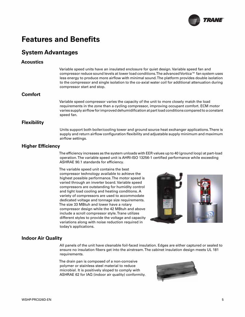
The variable speed unit contains the bestcompressor technology available to achieve thehighest possible performance.The motor speed isvaried through an inverter board. Variable speedcompressors are outstanding for humidity controland light load cooling and heating conditions. Avariety of compressors are used to accommodatededicated voltage and tonnage size requirements.The size 33 MBtuh and lower have a rotarycompressor design while the 42 MBtuh and aboveinclude a scroll compressor style.Trane utilizesdifferent styles to provide the voltage and capacityvariations along with noise reduction required intoday’s applications.
The drain pan is composed of a non-corrosivepolymer or stainless steel material to reducemicrobial. It is positively sloped to comply withASHRAE 62 for IAQ (indoor air quality) conformity.
WSHP-PRC026D-EN 5
Features and Benefits
A variety of filter options are available to meet most application requirements.The units areequipped with a disposable 1-inch thick fiberglass filter as standard. Disposable 2-inch thick filtersand 2-inch thick MERV 8 or MERV 13 filters are available as an option and will meet LEED EQ Credit5.
Integrated Controls
Reliability
Part-load operation reduces cyclic operation. Fewer on/off cycles reduce stress of the components.Every unit is factory run tested in both cooling and heating cycle.TheTracer™ UC400 controllerimproves quality and reliability with built in safeties and diagnostics.The controller provides anti-short cycle compressor protection, random start delay, heating/cooling status, occupied/unoccupied mode, filter maintenance timer, compressor status (high/low pressure), drive status(operating or failed) and condensate overflow protection.
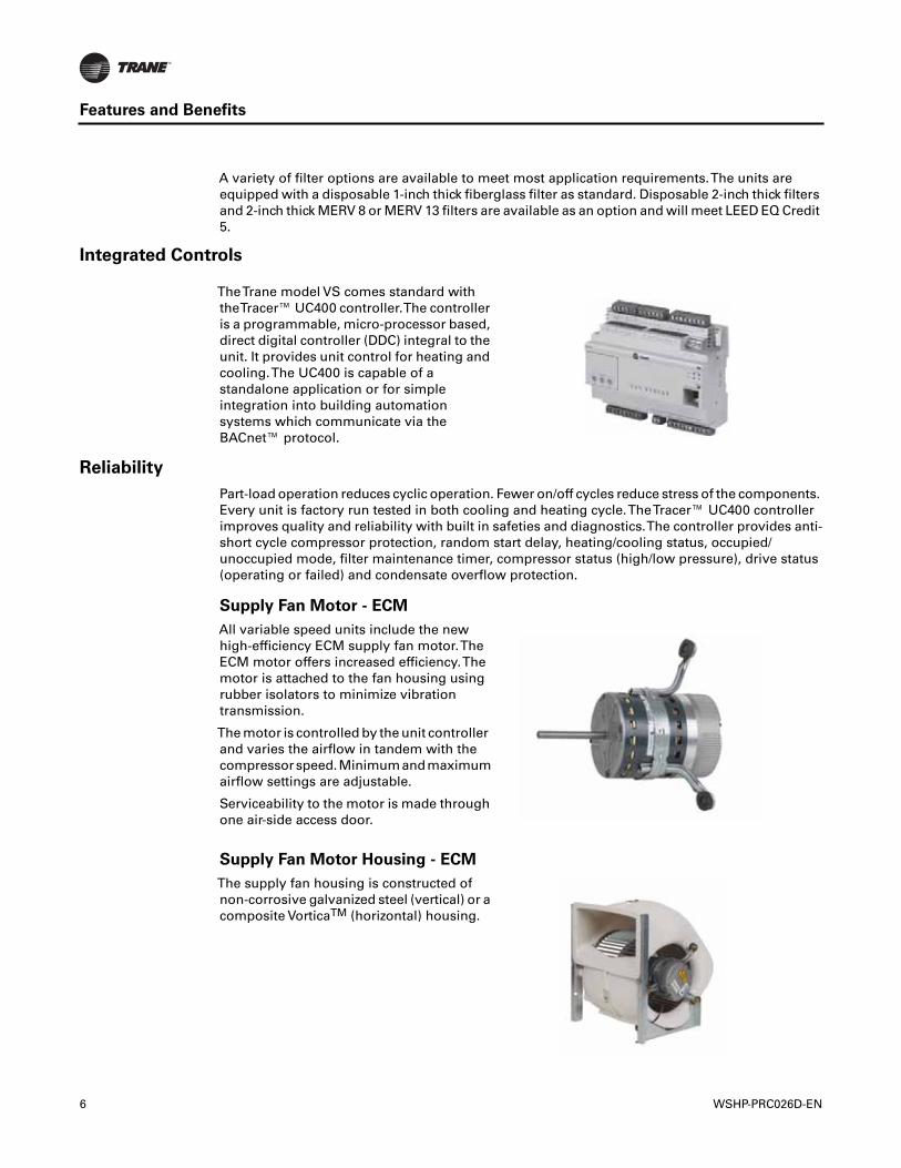
TheTrane model VS comes standard withtheTracer™ UC400 controller.The controlleris a programmable, micro-processor based,direct digital controller (DDC) integral to theunit. It provides unit control for heating andcooling.The UC400 is capable of astandalone application or for simpleintegration into building automationsystems which communicate via theBACnet™ protocol.
Supply Fan Motor - ECM
All variable speed units include the newhigh-efficiency ECM supply fan motor.TheECM motor offers increased efficiency.Themotor is attached to the fan housing usingrubber isolators to minimize vibrationtransmission.
The motor is controlled by the unit controllerand varies the airflow in tandem with thecompressorspeed.Minimumandmaximumairflow settings are adjustable.
Serviceability to the motor is made throughone air-side access door.
Supply Fan Motor Housing - ECM
The supply fan housing is constructed ofnon-corrosive galvanized steel (vertical) or acomposite VorticaTM (horizontal) housing.
6 WSHP-PRC026D-EN
Features and Benefits
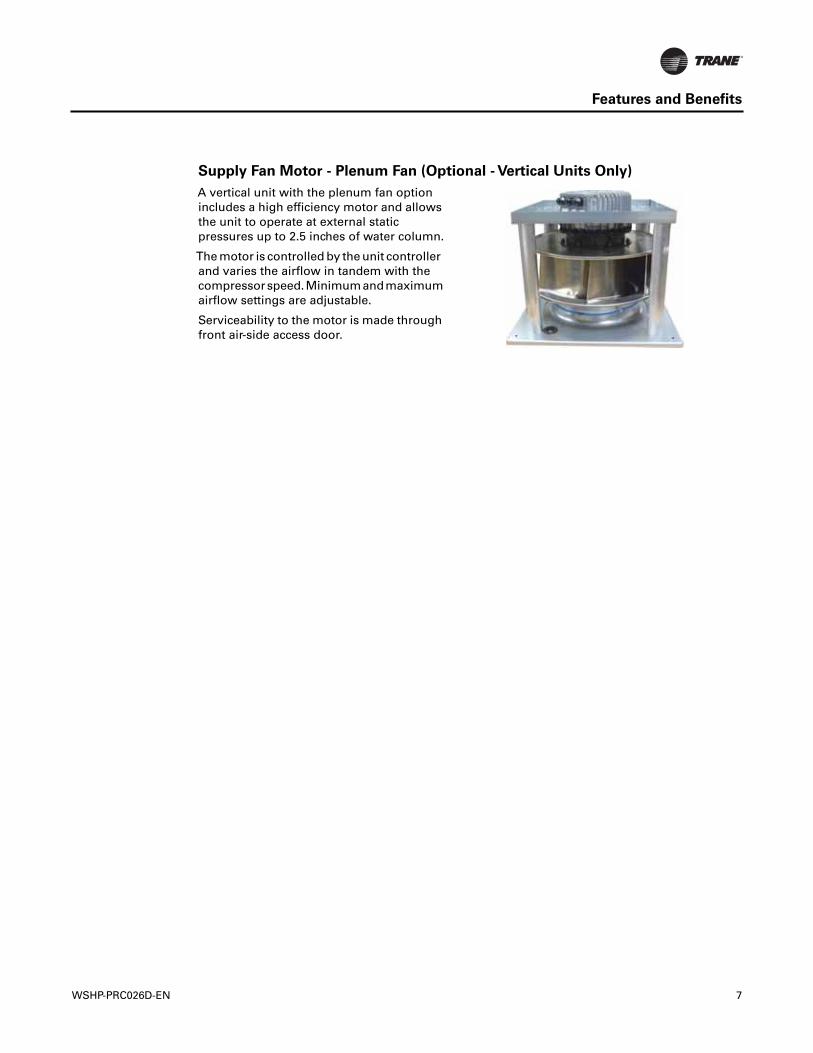
Supply Fan Motor - Plenum Fan (Optional - Vertical Units Only)
A vertical unit with the plenum fan optionincludes a high efficiency motor and allowsthe unit to operate at external staticpressures up to 2.5 inches of water column.
The motor is controlled by the unit controllerand varies the airflow in tandem with thecompressorspeed.Minimumandmaximumairflow settings are adjustable.
Serviceability to the motor is made throughfront air-side access door.
WSHP-PRC026D-EN 7
Application Considerations
Water-source heat pump systems are used to provide comfort in a wide range of building types andclimates.The system utilizes energy-conserving, heat-recovery capabilities to transfer heat fromone area to another to meet individual zone requirements. When used with system design andcontrol strategies, these high-performance systems reduce operating costs for the building ownerand improve occupant comfort. For more information on the design and control of these systems,refer to theTrane Water-Source and Ground-Source Heat Pump Systems application manual(literature number SYS-APM010-EN).
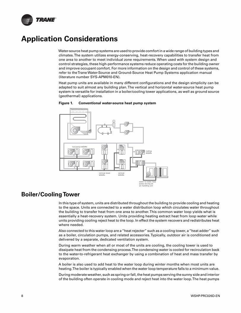
Heat pump units are available in many different configurations and the design simplicity can beadapted to suit almost any building plan.The vertical and horizontal water-source heat pumpsystem is versatile for installation in a boiler/cooling tower applications, as well as ground source(geothermal) applications.
Boiler/CoolingTower
In this type of system, units are distributed throughout the building to provide cooling and heatingto the space. Units are connected to a water distribution loop which circulates water throughoutthe building to transfer heat from one area to another.This common water loop yields what isessentially a heat-recovery system. Units providing heating extract heat from loop water whileunits providing cooling reject heat to the loop. In effect the system recovers and redistributes heatwhere needed.
Also connected to this water loop are a“heat rejecter” such as a cooling tower, a“heat adder” suchas a boiler, circulation pumps, and related accessories.Typically, outdoor air is conditioned anddelivered by a separate, dedicated ventilation system.
During warm weather when all or most of the units are cooling, the cooling tower is used todissipate heat from the condensing process.The condensing water is cooled for recirculation backto the water-to-refrigerant heat exchanger by using a combination of heat and mass transfer byevaporation.
A boiler is also used to add heat to the water loop during winter months when most units areheating.The boiler is typically enabled when the water loop temperature falls to a minimum value.
During moderate weather, such as spring or fall, the heat pumps serving the sunny side and interiorof the building often operate in cooling mode and reject heat into the water loop.The heat pumps
Figure 1. Conventional water-source heat pump system
horizontal WSHPs
vertical-stack WSHPs
verticalWSHPs
rooftopWSHPs
water-to-water heat pump serving an air-handling unit
8 WSHP-PRC026D-EN
Application Considerations
serving the shady side of the building often operate in heating mode and absorb heat from thewater loop.
Heat rejected by the units operating in cooling mode is used to offset the heat absorbed by the unitsin heating mode. In this manner, a WSHP system provides a form of heat recovery and anopportunity to save energy by reducing the need to operate the boiler or cooling tower. Forexample, if the water temperature stays in the desired range-between 60ºF (16ºC) and 90ºF (32ºC)-neither the boiler nor the cooling tower need to operate.
In applications such as office buildings, heat generated by lights, people, and office equipmentoften results in the need to provide year-round cooling in the interior zones of the building. In theseapplications, the benefit of this heat recovery further reduces boiler energy use during the wintermonths.
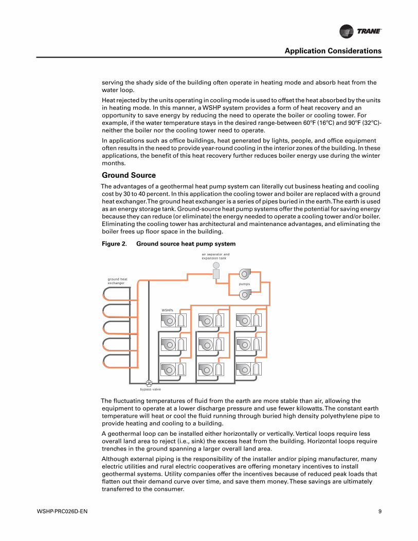
Ground Source
The advantages of a geothermal heat pump system can literally cut business heating and coolingcost by 30 to 40 percent. In this application the cooling tower and boiler are replaced with a groundheat exchanger.The ground heat exchanger is a series of pipes buried in the earth.The earth is usedas an energy storage tank. Ground-source heat pump systems offer the potential for saving energybecause they can reduce (or eliminate) the energy needed to operate a cooling tower and/or boiler.Eliminating the cooling tower has architectural and maintenance advantages, and eliminating theboiler frees up floor space in the building.
The fluctuating temperatures of fluid from the earth are more stable than air, allowing theequipment to operate at a lower discharge pressure and use fewer kilowatts.The constant earthtemperature will heat or cool the fluid running through buried high density polyethylene pipe toprovide heating and cooling to a building.
A geothermal loop can be installed either horizontally or vertically. Vertical loops require lessoverall land area to reject (i.e., sink) the excess heat from the building. Horizontal loops requiretrenches in the ground spanning a larger overall land area.
Although external piping is the responsibility of the installer and/or piping manufacturer, manyelectric utilities and rural electric cooperatives are offering monetary incentives to installgeothermal systems. Utility companies offer the incentives because of reduced peak loads thatflatten out their demand curve over time, and save them money.These savings are ultimatelytransferred to the consumer.
Figure 2. Ground source heat pump system
ground heat exchanger
air separator andexpansion tank
WSHPs
bypass valve
pumps
WSHP-PRC026D-EN 9
Application Considerations
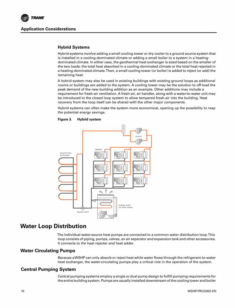
Hybrid Systems
Hybrid systems involve adding a small cooling tower or dry cooler to a ground source system thatis installed in a cooling-dominated climate or adding a small boiler to a system in a heating-dominated climate. In either case, the geothermal heat exchanger is sized based on the smaller ofthe two loads: the total heat absorbed in a cooling-dominated climate or the total heat rejected ina heating-dominated climate.Then, a small cooling tower (or boiler) is added to reject (or add) theremaining heat.
A hybrid system may also be used in existing buildings with existing ground loops as additionalrooms or buildings are added to the system. A cooling tower may be the solution to off-load thepeak demand of the new building addition as an example. Other additions may include arequirement for fresh-air ventilation. A fresh-air, air handler, along with a water-to-water unit maybe introduced to the closed loop system to allow tempered fresh-air into the building. Heatrecovery from the loop itself can be shared with the other major components.
Hybrid systems can often make the system more economical, opening up the possibility to reapthe potential energy savings.
Water Loop Distribution
The individual water-source heat pumps are connected to a common water distribution loop.Thisloop consists of piping, pumps, valves, an air separator and expansion tank and other accessories.It connects to the heat rejecter and heat adder.
Water Circulating Pumps
Because aWSHP can only absorb or reject heat while water flows through the refrigerant-to-waterheat exchanger, the water-circulating pumps play a critical role in the operation of the system.
Central Pumping System
Central pumping systems employ a single or dual pump design to fulfill pumping requirements forthe entire building system. Pumps are usually installed downstream of the cooling tower and boiler
Figure 3. Hybrid system
pumps
WSHPs
ground heatexchanger
bypass valve
cooling tower(or fluid cooler)
10 WSHP-PRC026D-EN
Application Considerations
and upstream of the units to ensure positive water pressure throughout the system.The mostcommon configuration is to use two pumps manifolded together with each pump sized to meet theflow requirements of the entire system. Only one of the pumps operates at any given time, withthe second available as “standby” pump in case the operating pump was to fail.
• Hose kits are used to connect the water supply and return line to the water inlets and outlets.Trane offers various hose kit combinations to better facilitate system flow balancing.Theseflexible hoses also aid in the reduction of vibration between the unit and the rigid central pipingsystem.
• A two position isolation valve is often applied to systems which incorporate variable frequencypumping.This valve is capable of stopping/starting water flow to the unit, which in turn reducesthe pumping requirements for the entire system.
• The central system supply and return lines should be sized to handle the required flow with aminimum pressure drop.
Note: Pipe will sweat if low temperature water is below the dew point of the surrounding space.Trane recommends that these lines be insulated to prevent damage from condensationwhen condenser loop is designed to be below 60°F. Equipment installed in attic/crawl spacetemperatures below 40°F may require antifreeze in the water loop.
Distributed Pumping System
A distributed pumping system contains a single pump module connected directly to the unit’ssupply and return.This module is typically field installed and piped to the unit.This design requiresindividual pump modules specifically sized for the flow requirement of the water-source heatpump. When the heat pump compressor turns off, the individual pump also turns off.
• Hose kits are used to connect the water supply and return line to the water inlets and outlets.Trane offers various hose kit combinations to better facilitate system flow balancing.Theseflexible hoses also aid in the reduction of vibration between the unit and the rigid central pipingsystem.
• Trane's self-contained pump module and hose kit make a complete pumping package fordistributed pumping systems.The module is designed for circulating commercial loops thatrequire a maximum flow rate of 20 gpm. Each pump module is fully assembled for connectionto water and electrical points.The kit contains all of the necessary components for theinstallation, operation and maintenance of a closed loop application. See WSHPC-IN-5 (72-9006-03) for electrical and dimensional requirements
• The distributed pumping system supply and return lines should be sized to handle the requiredflow with a minimum pressure drop.
Note: Pipe will sweat if low temperature water is below the dew point of the surrounding space.Trane recommends that these lines be insulated to prevent damage from condensationwhen condenser loop is designed to be below 60°F. Equipment installed in attic/crawl spacetemperatures below 40°F may require antifreeze in the water loop.
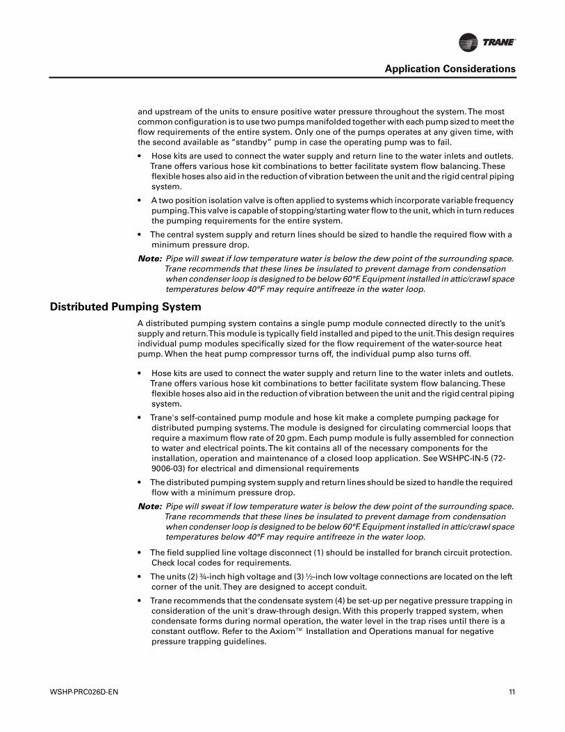
• The field supplied line voltage disconnect (1) should be installed for branch circuit protection.Check local codes for requirements.
• The units (2) ¾-inch high voltage and (3) ½-inch low voltage connections are located on the leftcorner of the unit.They are designed to accept conduit.
• Trane recommends that the condensate system (4) be set-up per negative pressure trapping inconsideration of the unit's draw-through design. With this properly trapped system, whencondensate forms during normal operation, the water level in the trap rises until there is aconstant outflow. Refer to the Axiom™ Installation and Operations manual for negativepressure trapping guidelines.
WSHP-PRC026D-EN 11
Application Considerations
• For acoustically sensitive areas, a ½-inch thick field provided vibration pad (5) should beinstalled below the vertical unit.This field provided piece should be equal to the overall foot-print size of the unit to provide sound damping of the unit while in operation.
• Hose kits (6) are used to connect the water supply and return lines to the water inlet and outlets.Trane includes various hose kit combinations to better facilitate system flow balancing.Theseflexible hoses, reduce vibration between the unit and the rigid piping system.
Duct Design for Noise Control
Proper acoustics are often a design requirement. Many problems associated with HVAC generatedsound can be avoided by properly selecting and locating the components of the system.Acousticalmodeling should be used to find the lowest cost design to meet a specific sound requirement.
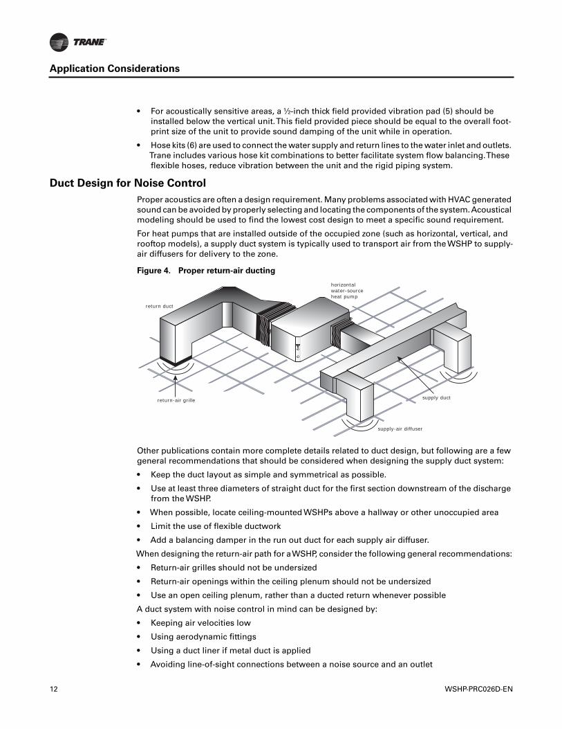
For heat pumps that are installed outside of the occupied zone (such as horizontal, vertical, androoftop models), a supply duct system is typically used to transport air from the WSHP to supply-air diffusers for delivery to the zone.
Other publications contain more complete details related to duct design, but following are a fewgeneral recommendations that should be considered when designing the supply duct system:
• Keep the duct layout as simple and symmetrical as possible.
• Use at least three diameters of straight duct for the first section downstream of the dischargefrom the WSHP.
• When possible, locate ceiling-mounted WSHPs above a hallway or other unoccupied area
• Limit the use of flexible ductwork
• Add a balancing damper in the run out duct for each supply air diffuser.
When designing the return-air path for aWSHP, consider the following general recommendations:
• Return-air grilles should not be undersized
• Return-air openings within the ceiling plenum should not be undersized
• Use an open ceiling plenum, rather than a ducted return whenever possible
A duct system with noise control in mind can be designed by:
• Keeping air velocities low
• Using aerodynamic fittings
• Using a duct liner if metal duct is applied
• Avoiding line-of-sight connections between a noise source and an outlet
Figure 4. Proper return-air ducting
return duct
return-air grille
horizontal water-sourceheat pump
supply-air diffuser
supply duct
12 WSHP-PRC026D-EN
Application Considerations
• Avoiding line-of-site connections between a noise source and an inlet
• Properly locating balancing dampers
• Sealing cracks, seams and joints in the duct run and equipment panels
• Blocking transmission through walls, ceiling and floor
• Mounting and supporting the ductwork with isolation devices that absorb vibration
• Using flexible duct connections
• Using flexible braided hoses on the water connections
For more information on best practices for the design and layout of duct systems, refer to the SheetMetal and Air Conditioning Contractors' National Association (SMACNA) manual, HVAC SystemsDuct Design.
Dehumidification
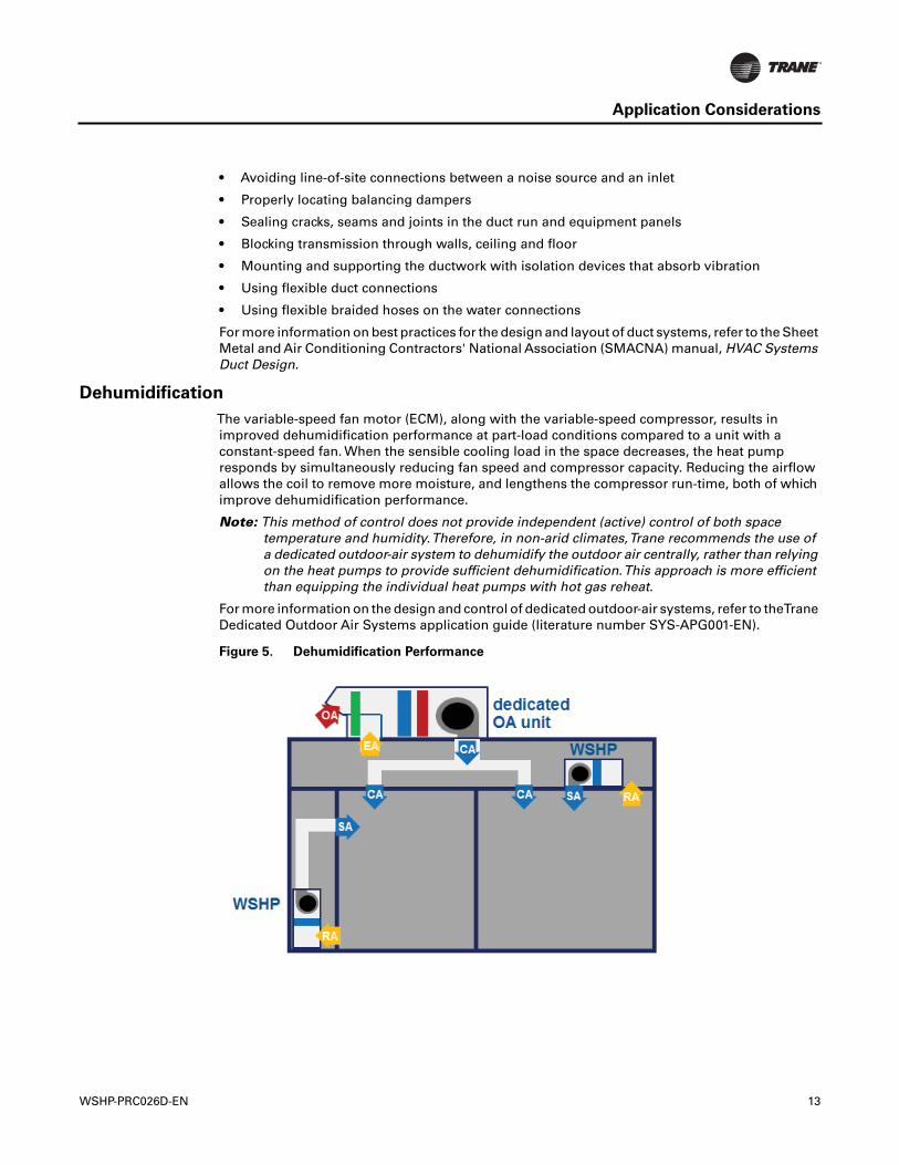
The variable-speed fan motor (ECM), along with the variable-speed compressor, results inimproved dehumidification performance at part-load conditions compared to a unit with aconstant-speed fan. When the sensible cooling load in the space decreases, the heat pumpresponds by simultaneously reducing fan speed and compressor capacity. Reducing the airflowallows the coil to remove more moisture, and lengthens the compressor run-time, both of whichimprove dehumidification performance.
Note: This method of control does not provide independent (active) control of both spacetemperature and humidity.Therefore, in non-arid climates,Trane recommends the use ofa dedicated outdoor-air system to dehumidify the outdoor air centrally, rather than relyingon the heat pumps to provide sufficient dehumidification.This approach is more efficientthan equipping the individual heat pumps with hot gas reheat.
For more information on the design and control of dedicated outdoor-air systems, refer to theTraneDedicated Outdoor Air Systems application guide (literature number SYS-APG001-EN).
Figure 5. Dehumidification Performance
WSHP-PRC026D-EN 13
0 4 2 3
5 6 7 8
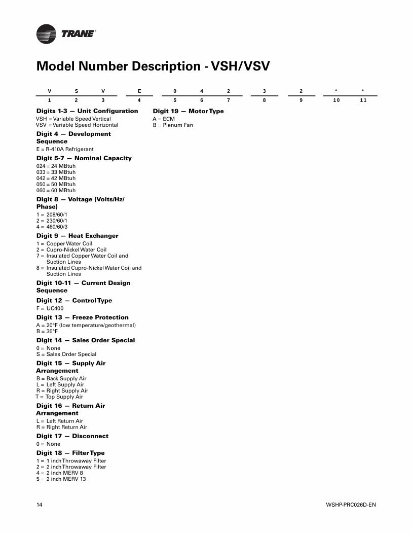
Model Number Description - VSH/VSV
Digits 1-3 — Unit ConfigurationVSH = Variable Speed VerticalVSV = Variable Speed Horizontal
Digit 4 — DevelopmentSequenceE = R-410A Refrigerant
Digit 5-7 — Nominal Capacity024 = 24 MBtuh033 = 33 MBtuh042 = 42 MBtuh050 = 50 MBtuh060 = 60 MBtuh
Digit 8 — Voltage (Volts/Hz/Phase)1 = 208/60/12 = 230/60/14 = 460/60/3
Digit 9 — Heat Exchanger1 = Copper Water Coil2 = Cupro-Nickel Water Coil7 = Insulated Copper Water Coil and
Suction Lines8 = Insulated Cupro-NickelWater Coil and
Suction Lines
Digit 10-11 — Current DesignSequence
Digit 12 — ControlTypeF = UC400
Digit 13 — Freeze ProtectionA = 20°F (low temperature/geothermal)B = 35°F
Digit 14 — Sales Order Special0 = NoneS = Sales Order Special
Digit 15 — Supply AirArrangementB = Back Supply AirL = Left Supply AirR = Right Supply AirT = Top Supply Air
Digit 16 — Return AirArrangementL = Left Return AirR = Right Return Air
Digit 17 — Disconnect0 = None
Digit 18 — FilterType1 = 1 inchThrowaway Filter2 = 2 inchThrowaway Filter4 = 2 inch MERV 85 = 2 inch MERV 13
V S V E
1 2 3 4
14
Digit 19 — MotorTypeA = ECMB = Plenum Fan
2 * *
9 10 11
WSHP-PRC026D-EN
General Data
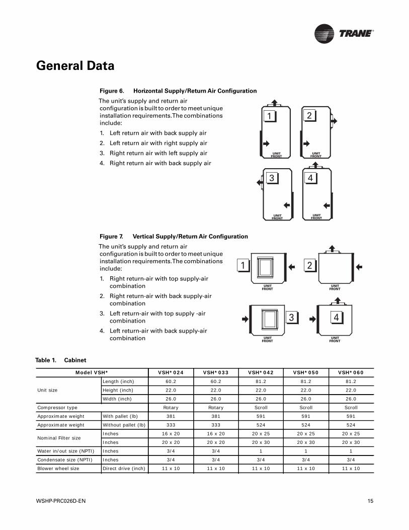
Figure 6. Horizontal Supply/Return Air Configuration
The unit’s supply and return airconfiguration is built to order to meet uniqueinstallation requirements.The combinationsinclude:
1. Left return air with back supply air
2. Left return air with right supply air
3. Right return air with left supply air
4. Right return air with back supply air
Figure 7. Vertical Supply/Return Air Configuration
The unit’s supply and return airconfiguration is built to order to meet uniqueinstallation requirements.The combinationsinclude:
1. Right return-air with top supply-aircombination
2. Right return-air with back supply-aircombination
3. Left return-air with top supply -aircombination
4. Left return-air with back supply-aircombination
3 4
UNITFRONT
UNITFRONT
1 2
UNITFRONT
UNITFRONT
UNITFRONT
1
UNITFRONT
2
UNITFRONT
3
UNITFRONT
4
Table 1. Cabinet
Model VSH* VSH*024 VSH*033 VSH*042 VSH*050 VSH*060
Unit size
Length (inch) 60.2 60.2 81.2 81.2 81.2
Height (inch) 22.0 22.0 22.0 22.0 22.0
Width (inch) 26.0 26.0 26.0 26.0 26.0
Compressor type Rotary Rotary Scroll Scroll Scroll
Approximate weight With pallet (lb) 381 381 591 591 591
Approximate weight Without pallet (lb) 333 333 524 524 524
Nominal Filter sizeInches 16 x 20 16 x 20 20 x 25 20 x 25 20 x 25
Inches 20 x 20 20 x 20 20 x 30 20 x 30 20 x 30
Water in/out size (NPTI) Inches 3/4 3/4 1 1 1
Condensate size (NPTI) Inches 3/4 3/4 3/4 3/4 3/4
Blower wheel size Direct drive (inch) 11 x 10 11 x 10 11 x 10 11 x 10 11 x 10
WSHP-PRC026D-EN 15
General Data
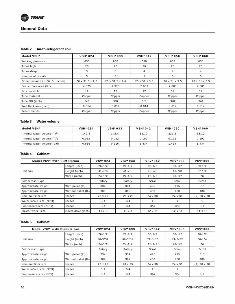
Table 2. Air-to-refrigerant coil
Model VSH* VSH*024 VSH*033 VSH*042 VSH*050 VSH*060
Working pressure 650 650 650 650 650
Tubes high 20 20 20 20 20
Tubes deep 3 3 4 4 4
Number of circuits 3 3 5 5 5
Finned volume (H, W, D: inches) 20 x 31.5 x 2.6 20 x 31.5 x 2.6 20 x 51 x 3.5 20 x 51 x 3.5 20 x 51 x 3.5
Coil surface area (ft2) 4.375 4.375 7.083 7.083 7.083
Fins per inch 12 12 12 12 12
Tube material Copper Copper Copper Copper Copper
Tube OD (inch) 3/8 3/8 3/8 3/8 3/8
Wall thickness (inch) 0.014 0.014 0.014 0.014 0.014
Return bends Copper Copper Copper Copper Copper
Table 3. Water volume
Model VSH* VSH*024 VSH*033 VSH*042 VSH*050 VSH*060
Internal water volume (in3) 142.4 142.4 331.2 331.2 331.2
Internal water volume (ft3) 0.082 0.082 0.192 0.192 0.192
Internal water volume (gal) 0.616 0.616 1.434 1.434 1.434
Table 4. Cabinet
Model VSV* with ECM Option VSV*024 VSV*033 VSV*042 VSV*050 VSV*060
Unit size
Length (inch) 26-1/2 26-1/2 30-1/2 30-1/2 30 1/2
Height (inch) 41-7/8 41-7/8 46-7/8 46-7/8 62 1/2
Width (inch) 24-1/2 24-1/2 26-1/2 26-1/2 26
Compressor type Rotary Rotary Scroll Scroll Scroll
Approximate weight With pallet (lb) 334 334 495 495 511
Approximate weight Without pallet (lb) 309 309 460 460 488
Nominal Filter size Inches 20 x 25 20 x 25 24 x 30 24 x 30 (2) 20 x 30
Water in/out size (NPTI) Inches 3/4 3/4 1 1 1
Condensate size (NPTI) Inches 3/4 3/4 3/4 3/4 3/4
Blower wheel size Direct drive (inch) 11 x 8 11 x 8 12 x 11 12 x 11 11 x 10
Table 5. Cabinet
Model VSV* with Plenum Fan VSV*024 VSV*033 VSV*042 VSV*050 VSV*060
Unit size
Length (inch) 26-1/2 26-1/2 30-1/2 30-1/2 30-1/2
Height (inch) 66-3/32 66-3/32 71-3/32 71-3/32 86-1/4
Width (inch) 24-1/2 24-1/2 26-1/2 26-1/2 26
Compressor type Rotary Rotary Scroll Scroll Scroll
Approximate weight With pallet (lb) 334 334 495 495 511
Approximate weight Without pallet (lb) 309 309 460 460 488
Nominal Filter size Inches 20 x 25 20 x 25 24 x 30 24 x 30 (2) 20 x 30
Water in/out size (NPTI) Inches 3/4 3/4 1 1 1
Condensate size (NPTI) Inches 3/4 3/4 3/4 3/4 3/4
16 WSHP-PRC026D-EN
General Data
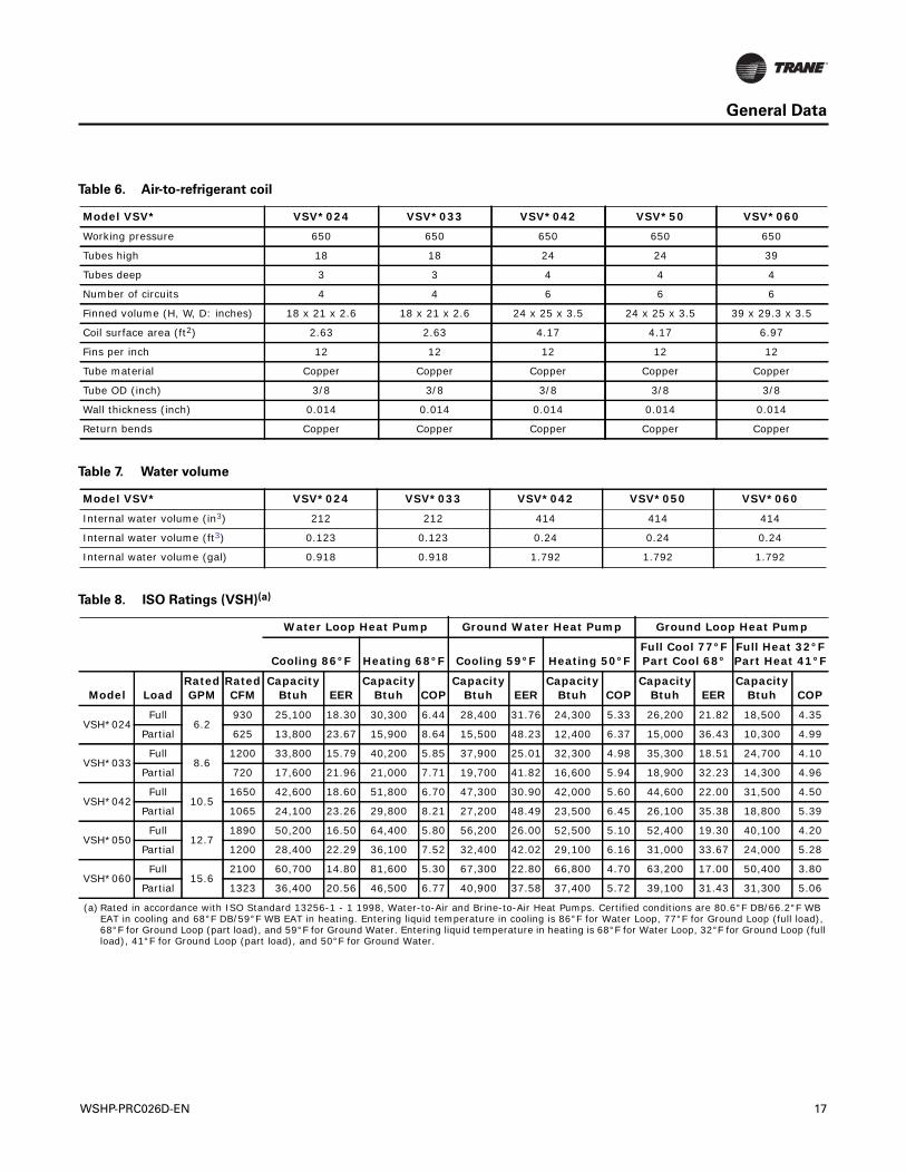
Table 6. Air-to-refrigerant coil
Model VSV* VSV*024 VSV*033 VSV*042 VSV*50 VSV*060
Working pressure 650 650 650 650 650
Tubes high 18 18 24 24 39
Tubes deep 3 3 4 4 4
Number of circuits 4 4 6 6 6
Finned volume (H, W, D: inches) 18 x 21 x 2.6 18 x 21 x 2.6 24 x 25 x 3.5 24 x 25 x 3.5 39 x 29.3 x 3.5
Coil surface area (ft2) 2.63 2.63 4.17 4.17 6.97
Fins per inch 12 12 12 12 12
Tube material Copper Copper Copper Copper Copper
Tube OD (inch) 3/8 3/8 3/8 3/8 3/8
Wall thickness (inch) 0.014 0.014 0.014 0.014 0.014
Return bends Copper Copper Copper Copper Copper
Table 7. Water volume
Model VSV* VSV*024 VSV*033 VSV*042 VSV*050 VSV*060
Internal water volume (in3) 212 212 414 414 414
Internal water volume (ft3) 0.123 0.123 0.24 0.24 0.24
Internal water volume (gal) 0.918 0.918 1.792 1.792 1.792
Table 8. ISO Ratings (VSH)(a)
Water Loop Heat Pump Ground Water Heat Pump Ground Loop Heat Pump
Cooling 86°F Heating 68°F Cooling 59°F Heating 50°FFull Cool 77°FPart Cool 68°
Full Heat 32°FPart Heat 41°F
Model LoadRatedGPM
Rated CFM
Capacity Btuh EER
Capacity Btuh COP
Capacity Btuh EER
Capacity Btuh COP
Capacity Btuh EER
Capacity Btuh COP
VSH*024Full
6.2 930 25,100 18.30 30,300 6.44 28,400 31.76 24,300 5.33 26,200 21.82 18,500 4.35
Partial 625 13,800 23.67 15,900 8.64 15,500 48.23 12,400 6.37 15,000 36.43 10,300 4.99
VSH*033Full
8.6 1200 33,800 15.79 40,200 5.85 37,900 25.01 32,300 4.98 35,300 18.51 24,700 4.10
Partial 720 17,600 21.96 21,000 7.71 19,700 41.82 16,600 5.94 18,900 32.23 14,300 4.96
VSH*042Full
10.5 1650 42,600 18.60 51,800 6.70 47,300 30.90 42,000 5.60 44,600 22.00 31,500 4.50
Partial 1065 24,100 23.26 29,800 8.21 27,200 48.49 23,500 6.45 26,100 35.38 18,800 5.39
VSH*050Full
12.7 1890 50,200 16.50 64,400 5.80 56,200 26.00 52,500 5.10 52,400 19.30 40,100 4.20
Partial 1200 28,400 22.29 36,100 7.52 32,400 42.02 29,100 6.16 31,000 33.67 24,000 5.28
VSH*060Full
15.6 2100 60,700 14.80 81,600 5.30 67,300 22.80 66,800 4.70 63,200 17.00 50,400 3.80
Partial 1323 36,400 20.56 46,500 6.77 40,900 37.58 37,400 5.72 39,100 31.43 31,300 5.06
(a) Rated in accordance with ISO Standard 13256-1 - 1 1998, Water-to-Air and Brine-to-Air Heat Pumps. Certified conditions are 80.6°F DB/66.2°F WB EAT in cooling and 68°F DB/59°F WB EAT in heating. Entering liquid temperature in cooling is 86°F for Water Loop, 77°F for Ground Loop (full load), 68°F for Ground Loop (part load), and 59°F for Ground Water. Entering liquid temperature in heating is 68°F for Water Loop, 32°F for Ground Loop (full load), 41°F for Ground Loop (part load), and 50°F for Ground Water.
WSHP-PRC026D-EN 17
General Data
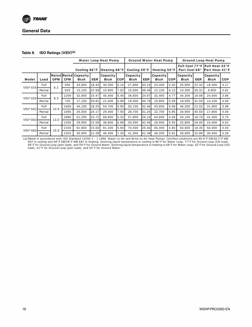
Table 9. ISO Ratings (VSV)(a)
Water Loop Heat Pump Ground Water Heat Pump Ground Loop Heat Pump
Cooling 86°F Heating 68°F Cooling 59°F Heating 50°FFull Cool 77°FPart Cool 68°
Full Heat 32°FPart Heat 41°F
Model LoadRatedGPM
Rated CFM
Capacity Btuh EER
Capacity Btuh COP
Capacity Btuh EER
Capacity Btuh COP
Capacity Btuh EER
Capacity Btuh COP
VSV*024Full
6.2 930 24,600 18.44 30,300 6.10 27,800 33.24 24,400 5.20 25,900 22.32 18,400 4.17
Partial 625 13,100 22.58 15,900 7.62 15,000 48.48 12,100 6.13 14,300 35.31 9,900 4.81
VSV*033Full
8.3 1200 32,900 15.47 40,400 5.46 36,600 24.67 32,400 4.77 34,300 18.08 24,500 3.86
Partial 720 17,100 20.81 21,500 6.96 19,400 40.79 16,800 5.59 18,500 31.59 14,100 4.60
VSV*042Full
10.9 1650 44,100 18.25 54,700 5.95 50,100 32.46 43,600 5.08 46,200 22.03 31,900 3.98
Partial 1065 25,500 24.17 29,400 7.50 28,700 51.26 22,700 5.85 26,900 40.50 17,800 4.59
VSV*050Full
13.0 1890 51,200 15.72 68,800 5.32 57,800 26.19 54,600 4.58 54,100 18.76 41,400 3.75
Partial 1200 29,900 22.08 36,800 6.88 33,500 42.46 28,500 5.50 32,800 34.00 23,400 4.62
VSV*060Full
15.6 2100 61,800 15.60 81,200 5.50 70,400 25.40 65,400 4.80 64,600 18.30 50,000 4.00
Partial 1323 35,900 21.28 46,300 7.30 41,300 41.38 36,200 5.91 39,600 32.88 30,400 5.29
(a) Rated in accordance with ISO Standard 13256-1 - 1 1998, Water-to-Air and Brine-to-Air Heat Pumps. Certified conditions are 80.6°F DB/66.2°F WB EAT in cooling and 68°F DB/59°F WB EAT in heating. Entering liquid temperature in cooling is 86°F for Water Loop, 77°F for Ground Loop (full load), 68°F for Ground Loop (part load), and 59°F for Ground Water. Entering liquid temperature in heating is 68°F for Water Loop, 32°F for Ground Loop (full load), 41°F for Ground Loop (part load), and 50°F for Ground Water.
18 WSHP-PRC026D-EN
Performance Data
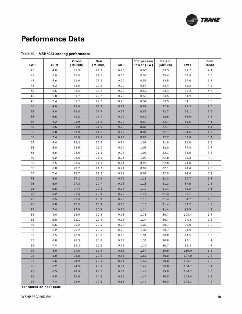
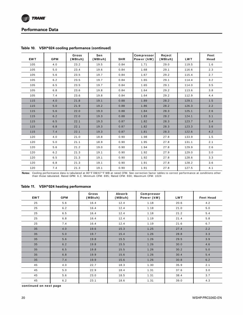
Table 10. VSH*024 cooling performance
EWT GPMGross
(MBtuh)Sen
(MBtuh) SHRCompressor Power (kW)
Reject (MBtuh) LWT
FeetHead
45 4.0 31.3 21.9 0.70 0.60 33.3 61.7 2.1
45 5.0 31.5 22.1 0.70 0.57 33.4 58.4 3.0
45 5.6 31.6 22.2 0.70 0.55 33.5 57.0 3.7
45 6.2 31.6 22.2 0.70 0.54 33.4 55.8 4.3
45 6.5 31.6 22.2 0.70 0.53 33.4 55.3 4.7
45 6.8 31.7 22.2 0.70 0.53 33.5 54.9 5.0
45 7.4 31.7 22.2 0.70 0.52 33.5 54.1 5.8
55 4.0 29.6 21.3 0.72 0.88 32.6 71.3 2.0
55 5.0 29.8 21.4 0.72 0.85 32.7 68.1 2.9
55 5.6 29.8 21.4 0.72 0.83 32.6 66.6 3.5
55 6.2 29.9 21.5 0.72 0.82 32.7 65.5 4.1
55 6.5 29.9 21.5 0.72 0.81 32.7 65.1 4.4
55 6.8 29.9 21.5 0.72 0.81 32.7 64.6 4.7
55 7.4 30.0 21.6 0.72 0.80 32.7 63.8 5.4
65 4.0 28.3 20.9 0.74 1.06 31.9 81.0 1.9
65 5.0 28.5 21.0 0.74 1.03 32.0 77.8 2.7
65 5.6 28.6 21.1 0.74 1.01 32.1 76.5 3.3
65 6.2 28.6 21.1 0.74 1.00 32.0 75.3 3.9
65 6.5 28.6 21.1 0.74 0.99 32.0 74.8 4.2
65 6.8 28.7 21.2 0.74 0.99 32.1 74.4 4.5
65 7.4 28.7 21.2 0.74 0.98 32.0 73.6 5.2
75 4.0 27.2 20.6 0.76 1.22 31.3 90.7 1.8
75 5.0 27.3 20.7 0.76 1.18 31.3 87.5 2.6
75 5.6 27.4 20.8 0.76 1.17 31.4 86.2 3.1
75 6.2 27.4 20.8 0.76 1.16 31.3 85.1 3.7
75 6.5 27.5 20.9 0.76 1.15 31.4 84.7 4.0
75 6.8 27.5 20.9 0.76 1.15 31.4 84.2 4.3
75 7.4 27.5 20.9 0.76 1.14 31.4 83.5 4.9
85 4.0 26.0 20.3 0.78 1.38 30.7 100.4 1.7
85 5.0 26.1 20.4 0.78 1.34 30.7 97.3 2.5
85 5.6 26.2 20.5 0.78 1.33 30.7 96.0 3.0
85 6.2 26.2 20.5 0.78 1.32 30.7 94.9 3.5
85 6.5 26.3 20.6 0.78 1.31 30.8 94.5 3.8
85 6.8 26.3 20.6 0.78 1.31 30.8 94.1 4.1
85 7.4 26.3 20.6 0.78 1.30 30.7 93.3 4.7
95 4.0 24.6 19.9 0.81 1.54 29.9 110.0 1.6
95 5.0 24.8 20.0 0.81 1.51 30.0 107.0 2.4
95 5.6 24.9 20.1 0.81 1.50 30.0 105.7 2.8
95 6.2 24.9 20.1 0.81 1.48 30.0 104.7 3.4
95 6.5 24.9 20.1 0.81 1.48 29.9 104.2 3.6
95 6.8 25.0 20.2 0.81 1.47 30.0 103.8 3.9
95 7.4 25.0 20.2 0.81 1.47 30.0 103.1 4.5
continued on next page
WSHP-PRC026D-EN 19
Performance Data
105 4.0 23.2 19.5 0.84 1.71 29.0 119.5 1.6
105 5.0 23.4 19.6 0.84 1.68 29.1 116.6 2.3
105 5.6 23.5 19.7 0.84 1.67 29.2 115.4 2.7
105 6.2 23.5 19.7 0.84 1.65 29.1 114.4 3.2
105 6.5 23.5 19.7 0.84 1.65 29.1 114.0 3.5
105 6.8 23.6 19.8 0.84 1.64 29.2 113.6 3.8
105 7.4 23.6 19.8 0.84 1.64 29.2 112.9 4.4
115 4.0 21.8 19.1 0.88 1.89 28.2 129.1 1.5
115 5.0 21.9 19.2 0.88 1.86 28.2 126.3 2.2
115 5.6 22.0 19.3 0.88 1.84 28.3 125.1 2.6
115 6.2 22.0 19.3 0.88 1.83 28.2 124.1 3.1
115 6.5 22.1 19.3 0.87 1.82 28.3 123.7 3.4
115 6.8 22.1 19.3 0.87 1.82 28.3 123.3 3.6
115 7.4 22.1 19.3 0.87 1.81 28.3 122.6 4.2
120 4.0 21.0 18.8 0.90 1.98 27.8 133.9 1.5
120 5.0 21.1 18.9 0.90 1.95 27.8 131.1 2.1
120 5.6 21.2 19.0 0.90 1.94 27.8 129.9 2.6
120 6.2 21.3 19.1 0.90 1.92 27.9 129.0 3.0
120 6.5 21.3 19.1 0.90 1.92 27.8 128.6 3.3
120 6.8 21.3 19.1 0.90 1.91 27.8 128.2 3.6
120 7.4 21.3 19.1 0.90 1.91 27.8 127.5 4.1
Notes: Cooling performance data is tabulated at 80°F DB/67°F WB at rated CFM. See correction factor tables to correct performance at conditions other than those tabulated. Rated GPM: 6.2; Minimum CFM: 695; Rated CFM: 930; Maximum CFM: 1024
Table 10. VSH*024 cooling performance (continued)
EWT GPMGross
(MBtuh)Sen
(MBtuh) SHRCompressor Power (kW)
Reject (MBtuh) LWT
FeetHead
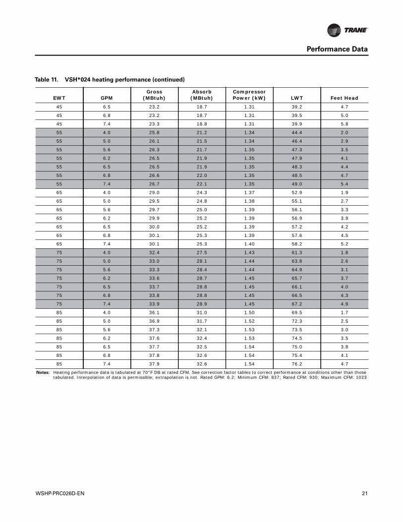
Table 11. VSH*024 heating performance
EWT GPMGross
(MBtuh)Absorb
(MBtuh)Compressor Power (kW) LWT Feet Head
25 5.6 16.4 12.4 1.18 20.6 4.2
25 6.2 16.4 12.4 1.18 21.0 5.0
25 6.5 16.4 12.4 1.18 21.2 5.4
25 6.8 16.4 12.4 1.19 21.4 5.8
25 7.4 16.4 12.4 1.19 21.6 6.7
35 4.0 19.6 15.3 1.25 27.4 2.2
35 5.0 19.7 15.4 1.26 28.8 3.3
35 5.6 19.8 15.5 1.26 29.5 3.9
35 6.2 19.8 15.5 1.26 30.0 4.6
35 6.5 19.8 15.5 1.26 30.2 5.0
35 6.8 19.9 15.6 1.26 30.4 5.4
35 7.4 19.9 15.6 1.26 30.8 6.2
45 4.0 22.7 18.3 1.30 35.9 2.1
45 5.0 22.9 18.4 1.31 37.6 3.0
45 5.6 23.0 18.5 1.31 38.4 3.7
45 6.2 23.1 18.6 1.31 39.0 4.3
continued on next page
20 WSHP-PRC026D-EN
Performance Data
45 6.5 23.2 18.7 1.31 39.2 4.7
45 6.8 23.2 18.7 1.31 39.5 5.0
45 7.4 23.3 18.8 1.31 39.9 5.8
55 4.0 25.8 21.2 1.34 44.4 2.0
55 5.0 26.1 21.5 1.34 46.4 2.9
55 5.6 26.3 21.7 1.35 47.3 3.5
55 6.2 26.5 21.9 1.35 47.9 4.1
55 6.5 26.5 21.9 1.35 48.3 4.4
55 6.8 26.6 22.0 1.35 48.5 4.7
55 7.4 26.7 22.1 1.35 49.0 5.4
65 4.0 29.0 24.3 1.37 52.9 1.9
65 5.0 29.5 24.8 1.38 55.1 2.7
65 5.6 29.7 25.0 1.39 56.1 3.3
65 6.2 29.9 25.2 1.39 56.9 3.9
65 6.5 30.0 25.2 1.39 57.2 4.2
65 6.8 30.1 25.3 1.39 57.6 4.5
65 7.4 30.1 25.3 1.40 58.2 5.2
75 4.0 32.4 27.5 1.43 61.3 1.8
75 5.0 33.0 28.1 1.44 63.8 2.6
75 5.6 33.3 28.4 1.44 64.9 3.1
75 6.2 33.6 28.7 1.45 65.7 3.7
75 6.5 33.7 28.8 1.45 66.1 4.0
75 6.8 33.8 28.8 1.45 66.5 4.3
75 7.4 33.9 28.9 1.45 67.2 4.9
85 4.0 36.1 31.0 1.50 69.5 1.7
85 5.0 36.9 31.7 1.52 72.3 2.5
85 5.6 37.3 32.1 1.53 73.5 3.0
85 6.2 37.6 32.4 1.53 74.5 3.5
85 6.5 37.7 32.5 1.54 75.0 3.8
85 6.8 37.8 32.6 1.54 75.4 4.1
85 7.4 37.9 32.6 1.54 76.2 4.7
Notes: Heating performance data is tabulated at 70°F DB at rated CFM. See correction factor tables to correct performance at conditions other than those tabulated. Interpolation of data is permissible; extrapolation is not. Rated GPM: 6.2; Minimum CFM: 837; Rated CFM: 930; Maximum CFM: 1023
Table 11. VSH*024 heating performance (continued)
EWT GPMGross
(MBtuh)Absorb
(MBtuh)Compressor Power (kW) LWT Feet Head
WSHP-PRC026D-EN 21
Performance Data
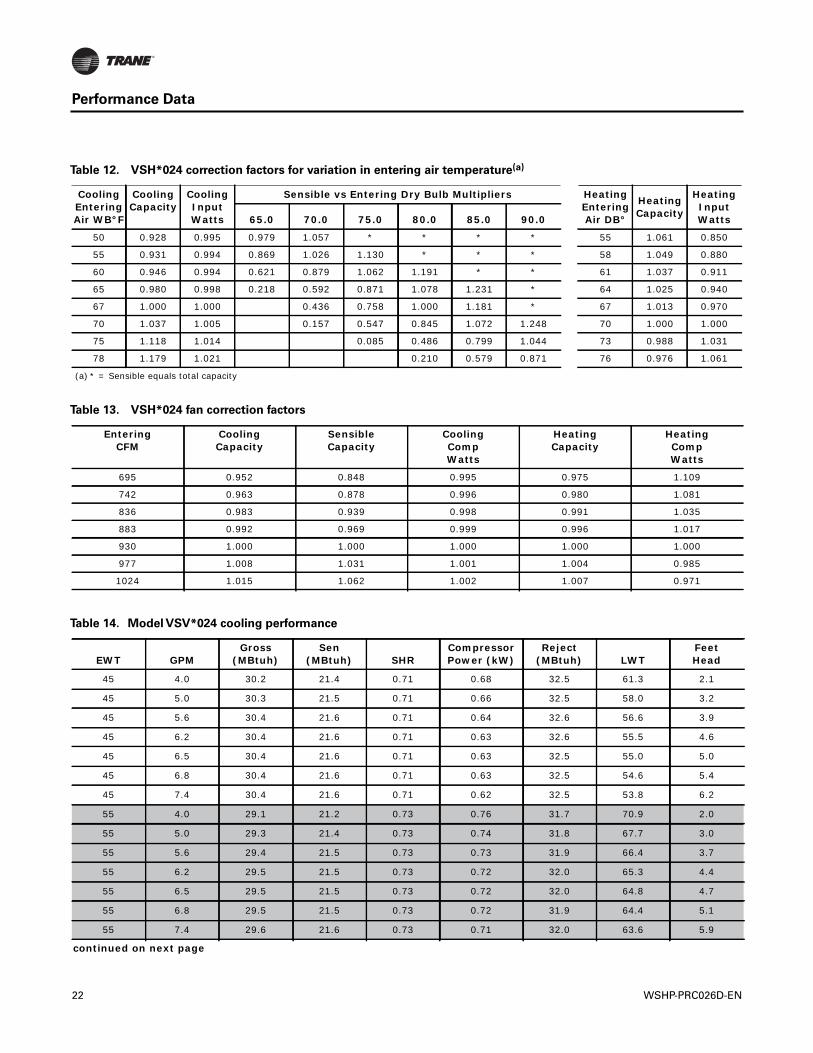
Table 12. VSH*024 correction factors for variation in entering air temperature(a)
Cooling Entering Air WB°F
Cooling Capacity
Cooling Input Watts
Sensible vs Entering Dry Bulb Multipliers Heating Entering Air DB°
Heating Capacity
Heating Input Watts65.0 70.0 75.0 80.0 85.0 90.0
50 0.928 0.995 0.979 1.057 * * * * 55 1.061 0.850
55 0.931 0.994 0.869 1.026 1.130 * * * 58 1.049 0.880
60 0.946 0.994 0.621 0.879 1.062 1.191 * * 61 1.037 0.911
65 0.980 0.998 0.218 0.592 0.871 1.078 1.231 * 64 1.025 0.940
67 1.000 1.000 0.436 0.758 1.000 1.181 * 67 1.013 0.970
70 1.037 1.005 0.157 0.547 0.845 1.072 1.248 70 1.000 1.000
75 1.118 1.014 0.085 0.486 0.799 1.044 73 0.988 1.031
78 1.179 1.021 0.210 0.579 0.871 76 0.976 1.061
(a) * = Sensible equals total capacity
Table 13. VSH*024 fan correction factors
Entering CFM
CoolingCapacity
SensibleCapacity
Cooling CompWatts
HeatingCapacity
Heating CompWatts
695 0.952 0.848 0.995 0.975 1.109
742 0.963 0.878 0.996 0.980 1.081
836 0.983 0.939 0.998 0.991 1.035
883 0.992 0.969 0.999 0.996 1.017
930 1.000 1.000 1.000 1.000 1.000
977 1.008 1.031 1.001 1.004 0.985
1024 1.015 1.062 1.002 1.007 0.971
Table 14. Model VSV*024 cooling performance
EWT GPMGross
(MBtuh)Sen
(MBtuh) SHRCompressor Power (kW)
Reject (MBtuh) LWT
FeetHead
45 4.0 30.2 21.4 0.71 0.68 32.5 61.3 2.1
45 5.0 30.3 21.5 0.71 0.66 32.5 58.0 3.2
45 5.6 30.4 21.6 0.71 0.64 32.6 56.6 3.9
45 6.2 30.4 21.6 0.71 0.63 32.6 55.5 4.6
45 6.5 30.4 21.6 0.71 0.63 32.5 55.0 5.0
45 6.8 30.4 21.6 0.71 0.63 32.5 54.6 5.4
45 7.4 30.4 21.6 0.71 0.62 32.5 53.8 6.2
55 4.0 29.1 21.2 0.73 0.76 31.7 70.9 2.0
55 5.0 29.3 21.4 0.73 0.74 31.8 67.7 3.0
55 5.6 29.4 21.5 0.73 0.73 31.9 66.4 3.7
55 6.2 29.5 21.5 0.73 0.72 32.0 65.3 4.4
55 6.5 29.5 21.5 0.73 0.72 32.0 64.8 4.7
55 6.8 29.5 21.5 0.73 0.72 31.9 64.4 5.1
55 7.4 29.6 21.6 0.73 0.71 32.0 63.6 5.9
continued on next page
22 WSHP-PRC026D-EN
Performance Data
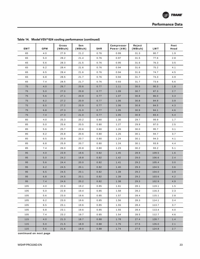
65 4.0 27.9 21.2 0.76 0.99 31.3 80.7 1.9
65 5.0 28.2 21.4 0.76 0.97 31.5 77.6 2.8
65 5.6 28.3 21.5 0.76 0.95 31.6 76.3 3.5
65 6.2 28.4 21.6 0.76 0.94 31.6 75.2 4.1
65 6.5 28.4 21.6 0.76 0.94 31.6 74.7 4.5
65 6.8 28.5 21.7 0.76 0.94 31.7 74.3 4.9
65 7.4 28.5 21.7 0.76 0.93 31.7 73.6 5.6
75 4.0 26.7 20.6 0.77 1.11 30.5 90.3 1.8
75 5.0 27.0 20.8 0.77 1.09 30.7 87.3 2.7
75 5.6 27.1 20.9 0.77 1.07 30.8 86.0 3.3
75 6.2 27.2 20.9 0.77 1.06 30.8 84.9 3.9
75 6.5 27.2 20.9 0.77 1.06 30.8 84.5 4.3
75 6.8 27.3 21.0 0.77 1.05 30.9 84.1 4.6
75 7.4 27.3 21.0 0.77 1.05 30.9 83.4 5.4
85 4.0 25.3 20.2 0.80 1.30 29.7 99.9 1.7
85 5.0 25.6 20.5 0.80 1.27 29.9 97.0 2.5
85 5.6 25.7 20.6 0.80 1.26 30.0 95.7 3.1
85 6.2 25.8 20.6 0.80 1.25 30.1 94.7 3.7
85 6.5 25.9 20.7 0.80 1.24 30.1 94.3 4.1
85 6.8 25.9 20.7 0.80 1.24 30.1 93.9 4.4
85 7.4 26.0 20.8 0.80 1.23 30.2 93.2 5.1
95 4.0 23.9 19.6 0.82 1.45 28.9 109.5 1.6
95 5.0 24.2 19.8 0.82 1.42 29.0 106.6 2.4
95 5.6 24.4 20.0 0.82 1.41 29.2 105.4 3.0
95 6.2 24.5 20.1 0.82 1.40 29.3 104.5 3.6
95 6.5 24.5 20.1 0.82 1.39 29.2 104.0 3.9
95 6.8 24.5 20.1 0.82 1.39 29.2 103.6 4.2
95 7.4 24.6 20.2 0.82 1.38 29.3 102.9 4.9
105 4.0 22.6 19.2 0.85 1.61 28.1 119.1 1.5
105 5.0 22.8 19.4 0.85 1.58 28.2 116.3 2.3
105 5.6 23.0 19.6 0.85 1.57 28.4 115.1 2.8
105 6.2 23.0 19.6 0.85 1.56 28.3 114.1 3.4
105 6.5 23.1 19.6 0.85 1.55 28.4 113.7 3.7
105 6.8 23.1 19.6 0.85 1.55 28.4 113.4 4.0
105 7.4 23.2 19.7 0.85 1.54 28.5 112.7 4.6
115 4.0 21.3 18.7 0.88 1.78 27.4 128.7 1.4
115 5.0 21.5 18.9 0.88 1.75 27.5 126.0 2.1
115 5.6 21.6 19.0 0.88 1.74 27.5 124.8 2.7
continued on next page
Table 14. Model VSV*024 cooling performance (continued)
EWT GPMGross
(MBtuh)Sen
(MBtuh) SHRCompressor Power (kW)
Reject (MBtuh) LWT
FeetHead
WSHP-PRC026D-EN 23
Performance Data
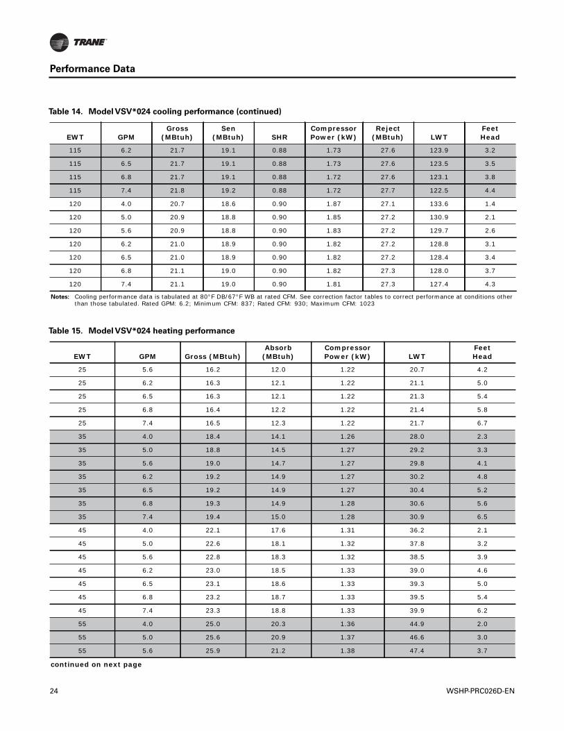
115 6.2 21.7 19.1 0.88 1.73 27.6 123.9 3.2
115 6.5 21.7 19.1 0.88 1.73 27.6 123.5 3.5
115 6.8 21.7 19.1 0.88 1.72 27.6 123.1 3.8
115 7.4 21.8 19.2 0.88 1.72 27.7 122.5 4.4
120 4.0 20.7 18.6 0.90 1.87 27.1 133.6 1.4
120 5.0 20.9 18.8 0.90 1.85 27.2 130.9 2.1
120 5.6 20.9 18.8 0.90 1.83 27.2 129.7 2.6
120 6.2 21.0 18.9 0.90 1.82 27.2 128.8 3.1
120 6.5 21.0 18.9 0.90 1.82 27.2 128.4 3.4
120 6.8 21.1 19.0 0.90 1.82 27.3 128.0 3.7
120 7.4 21.1 19.0 0.90 1.81 27.3 127.4 4.3
Notes: Cooling performance data is tabulated at 80°F DB/67°F WB at rated CFM. See correction factor tables to correct performance at conditions other than those tabulated. Rated GPM: 6.2; Minimum CFM: 837; Rated CFM: 930; Maximum CFM: 1023
Table 14. Model VSV*024 cooling performance (continued)
EWT GPMGross
(MBtuh)Sen
(MBtuh) SHRCompressor Power (kW)
Reject (MBtuh) LWT
FeetHead
Table 15. Model VSV*024 heating performance
EWT GPM Gross (MBtuh)Absorb
(MBtuh)Compressor Power (kW) LWT
FeetHead
25 5.6 16.2 12.0 1.22 20.7 4.2
25 6.2 16.3 12.1 1.22 21.1 5.0
25 6.5 16.3 12.1 1.22 21.3 5.4
25 6.8 16.4 12.2 1.22 21.4 5.8
25 7.4 16.5 12.3 1.22 21.7 6.7
35 4.0 18.4 14.1 1.26 28.0 2.3
35 5.0 18.8 14.5 1.27 29.2 3.3
35 5.6 19.0 14.7 1.27 29.8 4.1
35 6.2 19.2 14.9 1.27 30.2 4.8
35 6.5 19.2 14.9 1.27 30.4 5.2
35 6.8 19.3 14.9 1.28 30.6 5.6
35 7.4 19.4 15.0 1.28 30.9 6.5
45 4.0 22.1 17.6 1.31 36.2 2.1
45 5.0 22.6 18.1 1.32 37.8 3.2
45 5.6 22.8 18.3 1.32 38.5 3.9
45 6.2 23.0 18.5 1.33 39.0 4.6
45 6.5 23.1 18.6 1.33 39.3 5.0
45 6.8 23.2 18.7 1.33 39.5 5.4
45 7.4 23.3 18.8 1.33 39.9 6.2
55 4.0 25.0 20.3 1.36 44.9 2.0
55 5.0 25.6 20.9 1.37 46.6 3.0
55 5.6 25.9 21.2 1.38 47.4 3.7
continued on next page
24 WSHP-PRC026D-EN
Performance Data
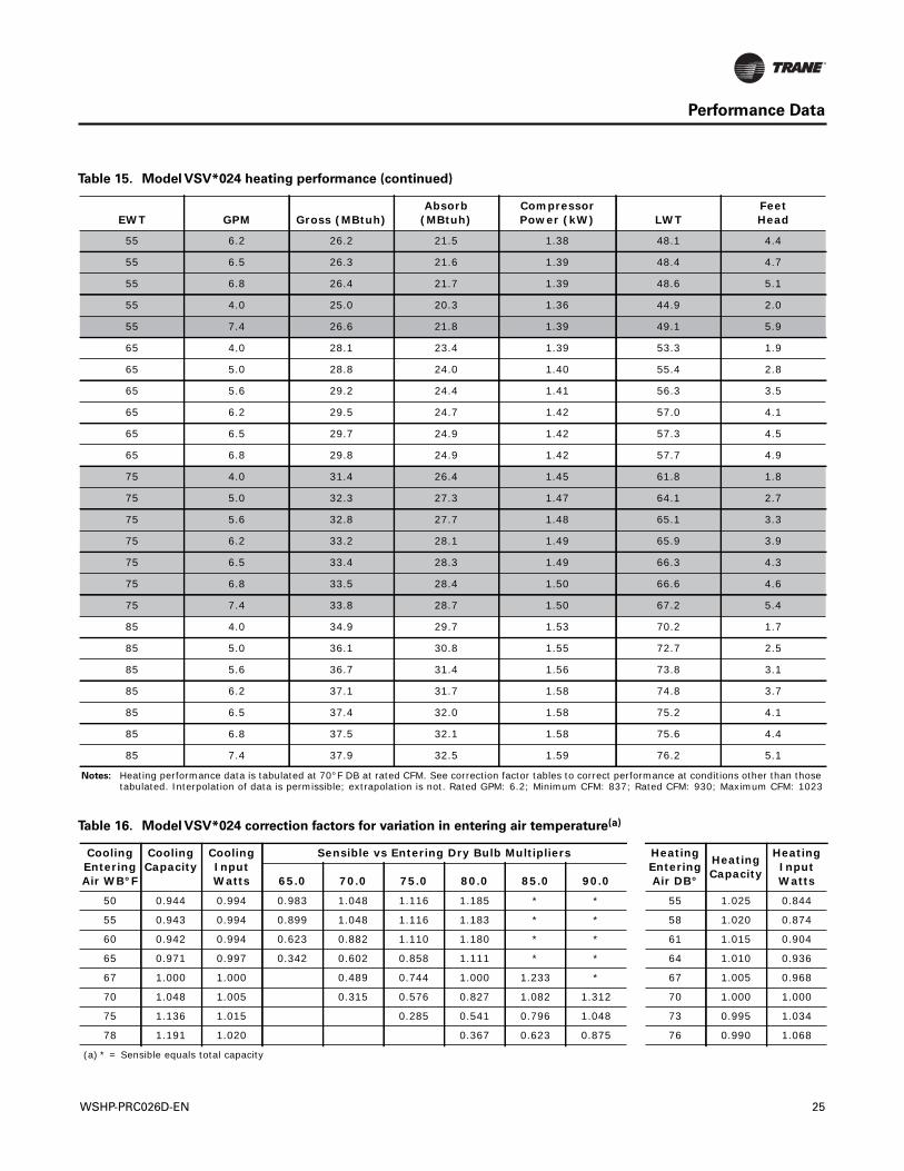
55 6.2 26.2 21.5 1.38 48.1 4.4
55 6.5 26.3 21.6 1.39 48.4 4.7
55 6.8 26.4 21.7 1.39 48.6 5.1
55 4.0 25.0 20.3 1.36 44.9 2.0
55 7.4 26.6 21.8 1.39 49.1 5.9
65 4.0 28.1 23.4 1.39 53.3 1.9
65 5.0 28.8 24.0 1.40 55.4 2.8
65 5.6 29.2 24.4 1.41 56.3 3.5
65 6.2 29.5 24.7 1.42 57.0 4.1
65 6.5 29.7 24.9 1.42 57.3 4.5
65 6.8 29.8 24.9 1.42 57.7 4.9
75 4.0 31.4 26.4 1.45 61.8 1.8
75 5.0 32.3 27.3 1.47 64.1 2.7
75 5.6 32.8 27.7 1.48 65.1 3.3
75 6.2 33.2 28.1 1.49 65.9 3.9
75 6.5 33.4 28.3 1.49 66.3 4.3
75 6.8 33.5 28.4 1.50 66.6 4.6
75 7.4 33.8 28.7 1.50 67.2 5.4
85 4.0 34.9 29.7 1.53 70.2 1.7
85 5.0 36.1 30.8 1.55 72.7 2.5
85 5.6 36.7 31.4 1.56 73.8 3.1
85 6.2 37.1 31.7 1.58 74.8 3.7
85 6.5 37.4 32.0 1.58 75.2 4.1
85 6.8 37.5 32.1 1.58 75.6 4.4
85 7.4 37.9 32.5 1.59 76.2 5.1
Notes: Heating performance data is tabulated at 70°F DB at rated CFM. See correction factor tables to correct performance at conditions other than those tabulated. Interpolation of data is permissible; extrapolation is not. Rated GPM: 6.2; Minimum CFM: 837; Rated CFM: 930; Maximum CFM: 1023
Table 15. Model VSV*024 heating performance (continued)
EWT GPM Gross (MBtuh)Absorb
(MBtuh)Compressor Power (kW) LWT
FeetHead
Table 16. Model VSV*024 correction factors for variation in entering air temperature(a)
Cooling Entering Air WB°F
Cooling Capacity
Cooling Input Watts
Sensible vs Entering Dry Bulb Multipliers Heating Entering Air DB°
Heating Capacity
Heating Input Watts65.0 70.0 75.0 80.0 85.0 90.0
50 0.944 0.994 0.983 1.048 1.116 1.185 * * 55 1.025 0.844
55 0.943 0.994 0.899 1.048 1.116 1.183 * * 58 1.020 0.874
60 0.942 0.994 0.623 0.882 1.110 1.180 * * 61 1.015 0.904
65 0.971 0.997 0.342 0.602 0.858 1.111 * * 64 1.010 0.936
67 1.000 1.000 0.489 0.744 1.000 1.233 * 67 1.005 0.968
70 1.048 1.005 0.315 0.576 0.827 1.082 1.312 70 1.000 1.000
75 1.136 1.015 0.285 0.541 0.796 1.048 73 0.995 1.034
78 1.191 1.020 0.367 0.623 0.875 76 0.990 1.068
(a) * = Sensible equals total capacity
WSHP-PRC026D-EN 25
Performance Data
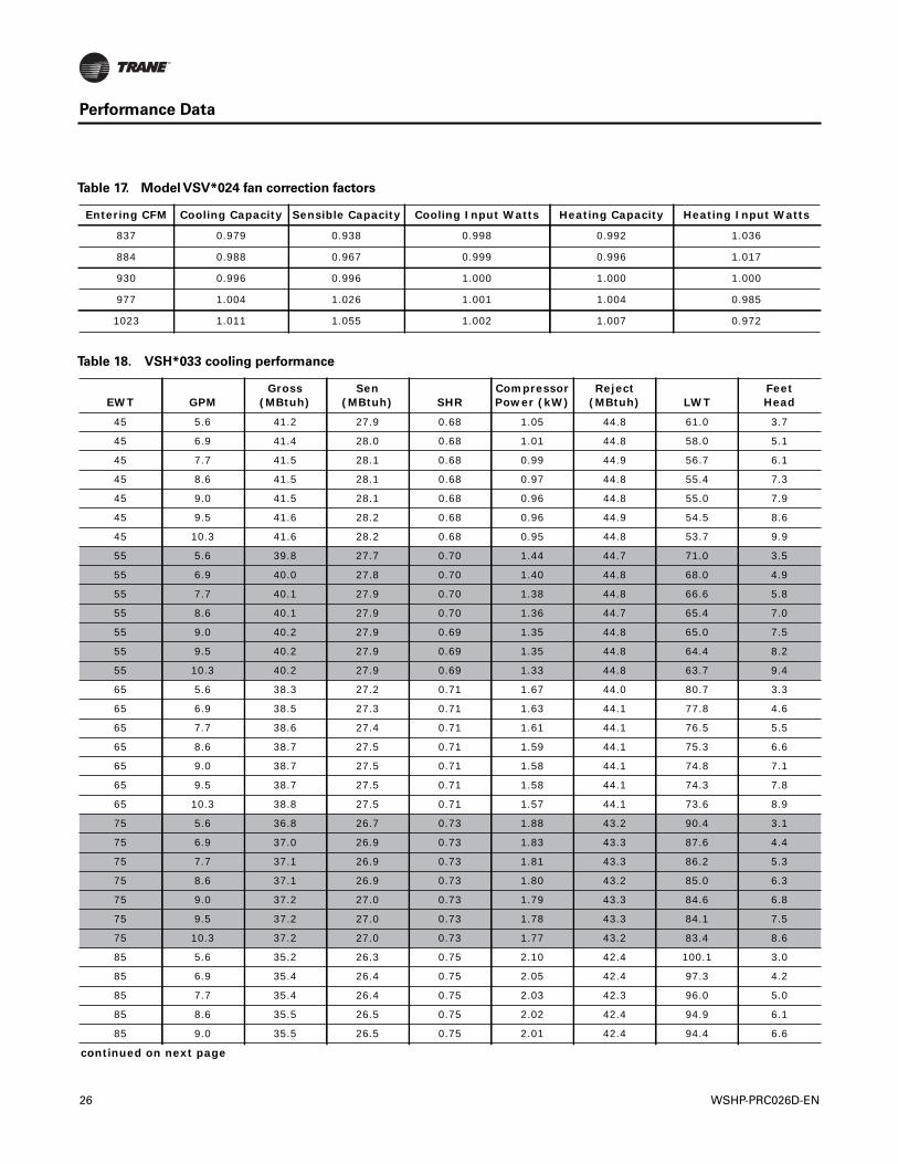
Table 17. Model VSV*024 fan correction factors
Entering CFM Cooling Capacity Sensible Capacity Cooling Input Watts Heating Capacity Heating Input Watts
837 0.979 0.938 0.998 0.992 1.036
884 0.988 0.967 0.999 0.996 1.017
930 0.996 0.996 1.000 1.000 1.000
977 1.004 1.026 1.001 1.004 0.985
1023 1.011 1.055 1.002 1.007 0.972
Table 18. VSH*033 cooling performance
EWT GPMGross
(MBtuh)Sen
(MBtuh) SHRCompressor Power (kW)
Reject (MBtuh) LWT
FeetHead
45 5.6 41.2 27.9 0.68 1.05 44.8 61.0 3.7
45 6.9 41.4 28.0 0.68 1.01 44.8 58.0 5.1
45 7.7 41.5 28.1 0.68 0.99 44.9 56.7 6.1
45 8.6 41.5 28.1 0.68 0.97 44.8 55.4 7.3
45 9.0 41.5 28.1 0.68 0.96 44.8 55.0 7.9
45 9.5 41.6 28.2 0.68 0.96 44.9 54.5 8.6
45 10.3 41.6 28.2 0.68 0.95 44.8 53.7 9.9
55 5.6 39.8 27.7 0.70 1.44 44.7 71.0 3.5
55 6.9 40.0 27.8 0.70 1.40 44.8 68.0 4.9
55 7.7 40.1 27.9 0.70 1.38 44.8 66.6 5.8
55 8.6 40.1 27.9 0.70 1.36 44.7 65.4 7.0
55 9.0 40.2 27.9 0.69 1.35 44.8 65.0 7.5
55 9.5 40.2 27.9 0.69 1.35 44.8 64.4 8.2
55 10.3 40.2 27.9 0.69 1.33 44.8 63.7 9.4
65 5.6 38.3 27.2 0.71 1.67 44.0 80.7 3.3
65 6.9 38.5 27.3 0.71 1.63 44.1 77.8 4.6
65 7.7 38.6 27.4 0.71 1.61 44.1 76.5 5.5
65 8.6 38.7 27.5 0.71 1.59 44.1 75.3 6.6
65 9.0 38.7 27.5 0.71 1.58 44.1 74.8 7.1
65 9.5 38.7 27.5 0.71 1.58 44.1 74.3 7.8
65 10.3 38.8 27.5 0.71 1.57 44.1 73.6 8.9
75 5.6 36.8 26.7 0.73 1.88 43.2 90.4 3.1
75 6.9 37.0 26.9 0.73 1.83 43.3 87.6 4.4
75 7.7 37.1 26.9 0.73 1.81 43.3 86.2 5.3
75 8.6 37.1 26.9 0.73 1.80 43.2 85.0 6.3
75 9.0 37.2 27.0 0.73 1.79 43.3 84.6 6.8
75 9.5 37.2 27.0 0.73 1.78 43.3 84.1 7.5
75 10.3 37.2 27.0 0.73 1.77 43.2 83.4 8.6
85 5.6 35.2 26.3 0.75 2.10 42.4 100.1 3.0
85 6.9 35.4 26.4 0.75 2.05 42.4 97.3 4.2
85 7.7 35.4 26.4 0.75 2.03 42.3 96.0 5.0
85 8.6 35.5 26.5 0.75 2.02 42.4 94.9 6.1
85 9.0 35.5 26.5 0.75 2.01 42.4 94.4 6.6
continued on next page
26 WSHP-PRC026D-EN
Performance Data
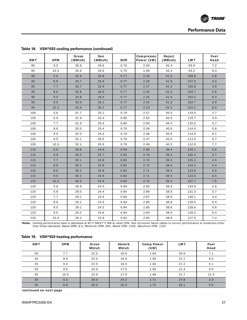
85 9.5 35.6 26.6 0.75 2.00 42.4 93.9 7.2
85 10.3 35.6 26.6 0.75 1.99 42.4 93.2 8.3
95 5.6 33.5 25.8 0.77 2.33 41.5 109.8 2.8
95 6.9 33.7 25.9 0.77 2.29 41.5 107.0 4.0
95 7.7 33.7 25.9 0.77 2.27 41.4 105.8 4.8
95 8.6 33.8 26.0 0.77 2.25 41.5 104.7 5.8
95 9.0 33.8 26.0 0.77 2.25 41.5 104.2 6.3
95 9.5 33.9 26.1 0.77 2.24 41.5 103.7 6.9
95 10.3 33.9 26.1 0.77 2.23 41.5 103.1 8.0
105 5.6 31.7 25.2 0.79 2.57 40.5 119.5 2.7
105 6.9 31.9 25.4 0.80 2.52 40.5 116.7 3.9
105 7.7 31.9 25.4 0.80 2.50 40.4 115.5 4.7
105 8.6 32.0 25.4 0.79 2.49 40.5 114.4 5.6
105 9.0 32.0 25.4 0.79 2.48 40.5 114.0 6.1
105 9.5 32.1 25.5 0.79 2.47 40.5 113.5 6.7
105 10.3 32.1 25.5 0.79 2.46 40.5 112.9 7.7
115 5.6 29.8 24.6 0.83 2.80 39.4 129.1 2.6
115 6.9 30.0 24.7 0.82 2.76 39.4 126.4 3.7
115 7.7 30.1 24.8 0.82 2.74 39.4 125.2 4.5
115 8.6 30.1 24.8 0.82 2.72 39.4 124.2 5.4
115 9.0 30.1 24.8 0.82 2.71 39.4 123.8 5.9
115 9.5 30.2 24.9 0.82 2.71 39.4 123.3 6.5
115 10.3 30.2 24.9 0.82 2.70 39.4 122.7 7.5
120 5.6 28.9 24.3 0.84 2.93 38.9 133.9 2.6
120 6.9 29.0 24.4 0.84 2.89 38.9 131.3 3.7
120 7.7 29.1 24.5 0.84 2.87 38.9 130.1 4.4
120 8.6 29.1 24.5 0.84 2.85 38.8 129.0 5.4
120 9.0 29.1 24.5 0.84 2.85 38.8 128.6 5.8
120 9.5 29.2 24.6 0.84 2.84 38.9 128.2 6.4
120 10.3 29.2 24.6 0.84 2.83 38.9 127.6 7.4
Notes: Cooling performance data is tabulated at 80°F DB/67°F WB at rated CFM. See correction factor tables to correct performance at conditions other than those tabulated. Rated GPM: 8.6; Minimum CFM: 891; Rated CFM: 1200; Maximum CFM: 1324
Table 18. VSH*033 cooling performance (continued)
EWT GPMGross
(MBtuh)Sen
(MBtuh) SHRCompressor Power (kW)
Reject (MBtuh) LWT
FeetHead
Table 19. VSH*033 heating performance
EWT GPM GrossMbtuh
AbsorbMbtuh
Comp Power(kW)
LWT FeetHead
25 7.7 22.5 16.9 1.64 20.6 7.1
25 8.6 22.5 16.9 1.65 21.1 8.5
25 9.0 22.5 16.9 1.65 21.2 9.1
25 9.5 22.6 17.0 1.65 21.4 9.9
25 10.3 22.6 17.0 1.66 21.7 11.3
35 5.6 26.0 20.2 1.71 27.8 3.9
35 6.9 26.2 20.3 1.72 29.1 5.5
continued on next page
WSHP-PRC026D-EN 27
Performance Data
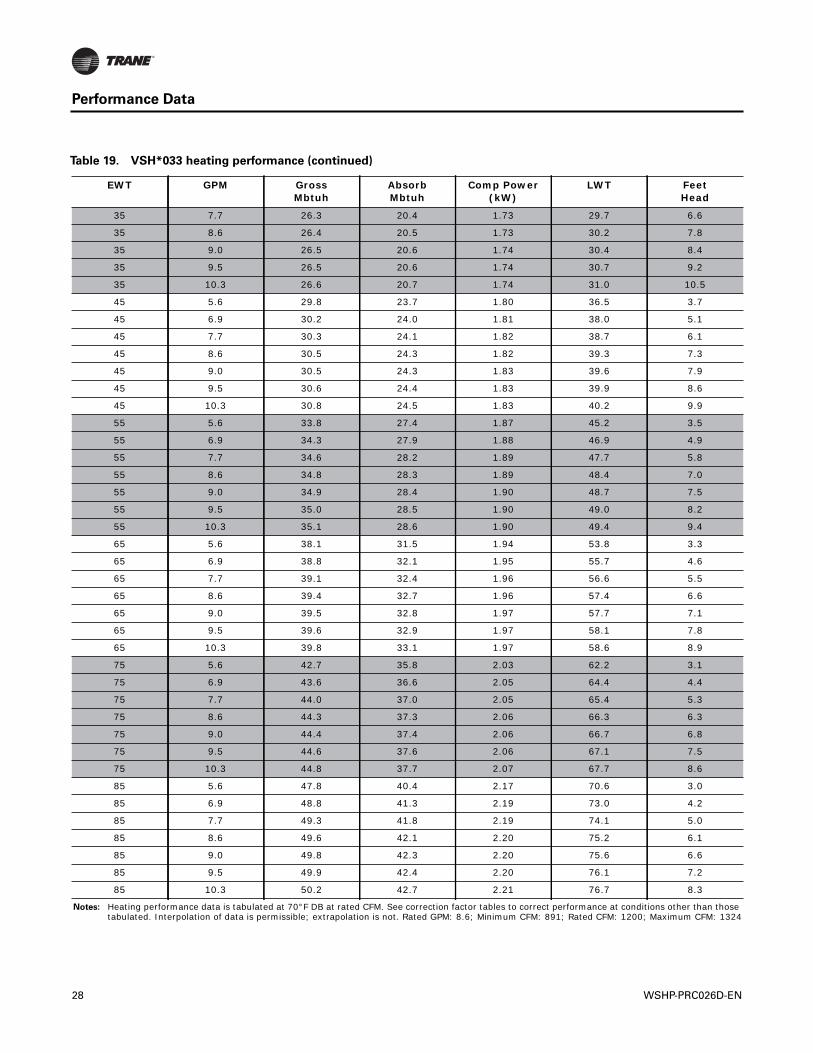
35 7.7 26.3 20.4 1.73 29.7 6.6
35 8.6 26.4 20.5 1.73 30.2 7.8
35 9.0 26.5 20.6 1.74 30.4 8.4
35 9.5 26.5 20.6 1.74 30.7 9.2
35 10.3 26.6 20.7 1.74 31.0 10.5
45 5.6 29.8 23.7 1.80 36.5 3.7
45 6.9 30.2 24.0 1.81 38.0 5.1
45 7.7 30.3 24.1 1.82 38.7 6.1
45 8.6 30.5 24.3 1.82 39.3 7.3
45 9.0 30.5 24.3 1.83 39.6 7.9
45 9.5 30.6 24.4 1.83 39.9 8.6
45 10.3 30.8 24.5 1.83 40.2 9.9
55 5.6 33.8 27.4 1.87 45.2 3.5
55 6.9 34.3 27.9 1.88 46.9 4.9
55 7.7 34.6 28.2 1.89 47.7 5.8
55 8.6 34.8 28.3 1.89 48.4 7.0
55 9.0 34.9 28.4 1.90 48.7 7.5
55 9.5 35.0 28.5 1.90 49.0 8.2
55 10.3 35.1 28.6 1.90 49.4 9.4
65 5.6 38.1 31.5 1.94 53.8 3.3
65 6.9 38.8 32.1 1.95 55.7 4.6
65 7.7 39.1 32.4 1.96 56.6 5.5
65 8.6 39.4 32.7 1.96 57.4 6.6
65 9.0 39.5 32.8 1.97 57.7 7.1
65 9.5 39.6 32.9 1.97 58.1 7.8
65 10.3 39.8 33.1 1.97 58.6 8.9
75 5.6 42.7 35.8 2.03 62.2 3.1
75 6.9 43.6 36.6 2.05 64.4 4.4
75 7.7 44.0 37.0 2.05 65.4 5.3
75 8.6 44.3 37.3 2.06 66.3 6.3
75 9.0 44.4 37.4 2.06 66.7 6.8
75 9.5 44.6 37.6 2.06 67.1 7.5
75 10.3 44.8 37.7 2.07 67.7 8.6
85 5.6 47.8 40.4 2.17 70.6 3.0
85 6.9 48.8 41.3 2.19 73.0 4.2
85 7.7 49.3 41.8 2.19 74.1 5.0
85 8.6 49.6 42.1 2.20 75.2 6.1
85 9.0 49.8 42.3 2.20 75.6 6.6
85 9.5 49.9 42.4 2.20 76.1 7.2
85 10.3 50.2 42.7 2.21 76.7 8.3
Notes: Heating performance data is tabulated at 70°F DB at rated CFM. See correction factor tables to correct performance at conditions other than those tabulated. Interpolation of data is permissible; extrapolation is not. Rated GPM: 8.6; Minimum CFM: 891; Rated CFM: 1200; Maximum CFM: 1324
Table 19. VSH*033 heating performance (continued)
EWT GPM GrossMbtuh
AbsorbMbtuh
Comp Power(kW)
LWT FeetHead
28 WSHP-PRC026D-EN
Performance Data
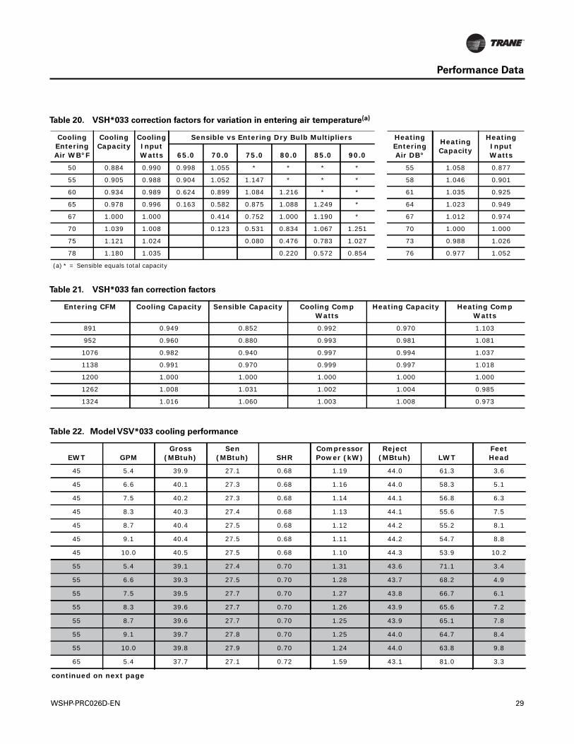
Table 20. VSH*033 correction factors for variation in entering air temperature(a)
Cooling Entering Air WB°F
Cooling Capacity
Cooling Input Watts
Sensible vs Entering Dry Bulb Multipliers Heating Entering Air DB°
Heating Capacity
Heating Input Watts65.0 70.0 75.0 80.0 85.0 90.0
50 0.884 0.990 0.998 1.055 * * * * 55 1.058 0.877
55 0.905 0.988 0.904 1.052 1.147 * * * 58 1.046 0.901
60 0.934 0.989 0.624 0.899 1.084 1.216 * * 61 1.035 0.925
65 0.978 0.996 0.163 0.582 0.875 1.088 1.249 * 64 1.023 0.949
67 1.000 1.000 0.414 0.752 1.000 1.190 * 67 1.012 0.974
70 1.039 1.008 0.123 0.531 0.834 1.067 1.251 70 1.000 1.000
75 1.121 1.024 0.080 0.476 0.783 1.027 73 0.988 1.026
78 1.180 1.035 0.220 0.572 0.854 76 0.977 1.052
(a) * = Sensible equals total capacity
Table 21. VSH*033 fan correction factors
Entering CFM Cooling Capacity Sensible Capacity Cooling Comp Watts
Heating Capacity Heating Comp Watts
891 0.949 0.852 0.992 0.970 1.103
952 0.960 0.880 0.993 0.981 1.081
1076 0.982 0.940 0.997 0.994 1.037
1138 0.991 0.970 0.999 0.997 1.018
1200 1.000 1.000 1.000 1.000 1.000
1262 1.008 1.031 1.002 1.004 0.985
1324 1.016 1.060 1.003 1.008 0.973
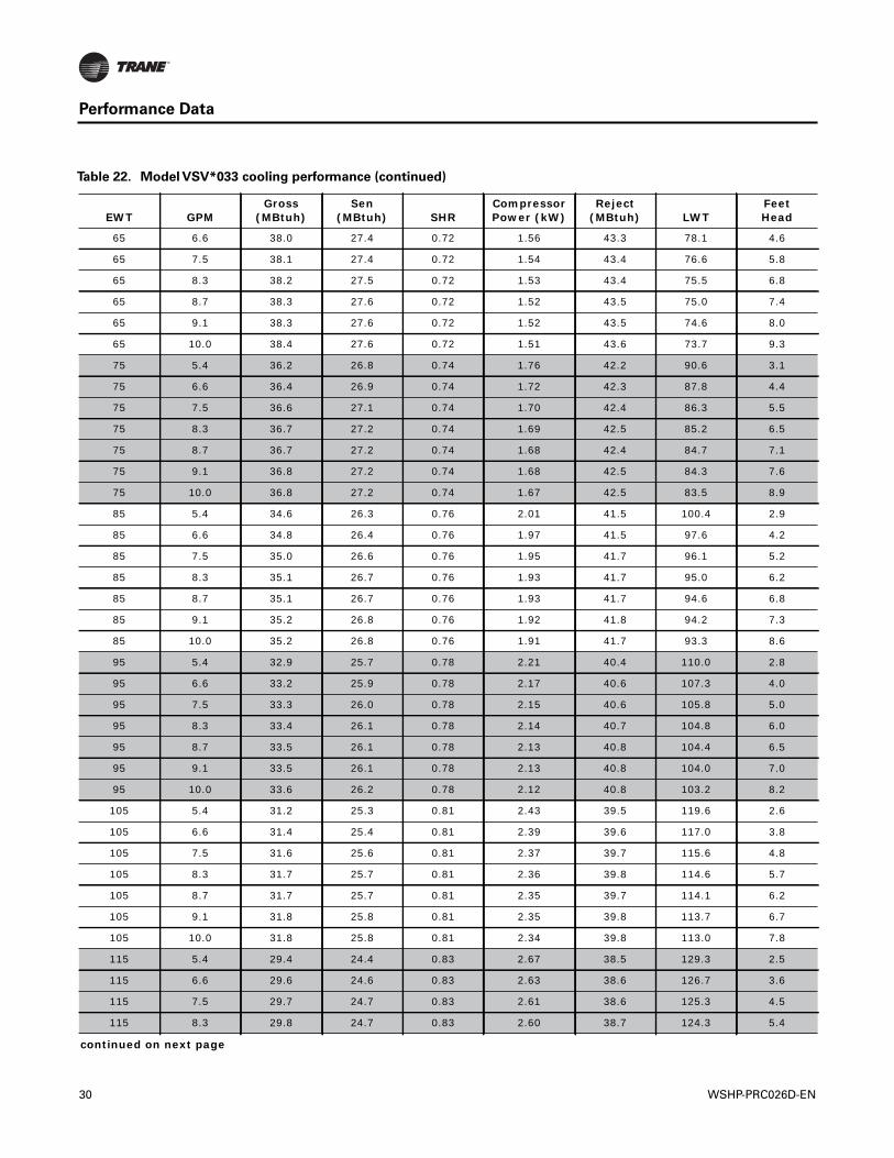
Table 22. Model VSV*033 cooling performance
EWT GPMGross
(MBtuh)Sen
(MBtuh) SHRCompressor Power (kW)
Reject (MBtuh) LWT
FeetHead
45 5.4 39.9 27.1 0.68 1.19 44.0 61.3 3.6
45 6.6 40.1 27.3 0.68 1.16 44.0 58.3 5.1
45 7.5 40.2 27.3 0.68 1.14 44.1 56.8 6.3
45 8.3 40.3 27.4 0.68 1.13 44.1 55.6 7.5
45 8.7 40.4 27.5 0.68 1.12 44.2 55.2 8.1
45 9.1 40.4 27.5 0.68 1.11 44.2 54.7 8.8
45 10.0 40.5 27.5 0.68 1.10 44.3 53.9 10.2
55 5.4 39.1 27.4 0.70 1.31 43.6 71.1 3.4
55 6.6 39.3 27.5 0.70 1.28 43.7 68.2 4.9
55 7.5 39.5 27.7 0.70 1.27 43.8 66.7 6.1
55 8.3 39.6 27.7 0.70 1.26 43.9 65.6 7.2
55 8.7 39.6 27.7 0.70 1.25 43.9 65.1 7.8
55 9.1 39.7 27.8 0.70 1.25 44.0 64.7 8.4
55 10.0 39.8 27.9 0.70 1.24 44.0 63.8 9.8
65 5.4 37.7 27.1 0.72 1.59 43.1 81.0 3.3
continued on next page
WSHP-PRC026D-EN 29
Performance Data
65 6.6 38.0 27.4 0.72 1.56 43.3 78.1 4.6
65 7.5 38.1 27.4 0.72 1.54 43.4 76.6 5.8
65 8.3 38.2 27.5 0.72 1.53 43.4 75.5 6.8
65 8.7 38.3 27.6 0.72 1.52 43.5 75.0 7.4
65 9.1 38.3 27.6 0.72 1.52 43.5 74.6 8.0
65 10.0 38.4 27.6 0.72 1.51 43.6 73.7 9.3
75 5.4 36.2 26.8 0.74 1.76 42.2 90.6 3.1
75 6.6 36.4 26.9 0.74 1.72 42.3 87.8 4.4
75 7.5 36.6 27.1 0.74 1.70 42.4 86.3 5.5
75 8.3 36.7 27.2 0.74 1.69 42.5 85.2 6.5
75 8.7 36.7 27.2 0.74 1.68 42.4 84.7 7.1
75 9.1 36.8 27.2 0.74 1.68 42.5 84.3 7.6
75 10.0 36.8 27.2 0.74 1.67 42.5 83.5 8.9
85 5.4 34.6 26.3 0.76 2.01 41.5 100.4 2.9
85 6.6 34.8 26.4 0.76 1.97 41.5 97.6 4.2
85 7.5 35.0 26.6 0.76 1.95 41.7 96.1 5.2
85 8.3 35.1 26.7 0.76 1.93 41.7 95.0 6.2
85 8.7 35.1 26.7 0.76 1.93 41.7 94.6 6.8
85 9.1 35.2 26.8 0.76 1.92 41.8 94.2 7.3
85 10.0 35.2 26.8 0.76 1.91 41.7 93.3 8.6
95 5.4 32.9 25.7 0.78 2.21 40.4 110.0 2.8
95 6.6 33.2 25.9 0.78 2.17 40.6 107.3 4.0
95 7.5 33.3 26.0 0.78 2.15 40.6 105.8 5.0
95 8.3 33.4 26.1 0.78 2.14 40.7 104.8 6.0
95 8.7 33.5 26.1 0.78 2.13 40.8 104.4 6.5
95 9.1 33.5 26.1 0.78 2.13 40.8 104.0 7.0
95 10.0 33.6 26.2 0.78 2.12 40.8 103.2 8.2
105 5.4 31.2 25.3 0.81 2.43 39.5 119.6 2.6
105 6.6 31.4 25.4 0.81 2.39 39.6 117.0 3.8
105 7.5 31.6 25.6 0.81 2.37 39.7 115.6 4.8
105 8.3 31.7 25.7 0.81 2.36 39.8 114.6 5.7
105 8.7 31.7 25.7 0.81 2.35 39.7 114.1 6.2
105 9.1 31.8 25.8 0.81 2.35 39.8 113.7 6.7
105 10.0 31.8 25.8 0.81 2.34 39.8 113.0 7.8
115 5.4 29.4 24.4 0.83 2.67 38.5 129.3 2.5
115 6.6 29.6 24.6 0.83 2.63 38.6 126.7 3.6
115 7.5 29.7 24.7 0.83 2.61 38.6 125.3 4.5
115 8.3 29.8 24.7 0.83 2.60 38.7 124.3 5.4
continued on next page
Table 22. Model VSV*033 cooling performance (continued)
EWT GPMGross
(MBtuh)Sen
(MBtuh) SHRCompressor Power (kW)
Reject (MBtuh) LWT
FeetHead
30 WSHP-PRC026D-EN
Performance Data
115 8.7 29.9 24.8 0.83 2.60 38.8 123.9 5.9
115 9.1 29.9 24.8 0.83 2.59 38.7 123.5 6.4
115 10.0 30.0 24.9 0.83 2.58 38.8 122.8 7.5
120 5.4 28.4 24.1 0.85 2.79 37.9 134.0 2.4
120 6.6 28.6 24.3 0.85 2.76 38.0 131.5 3.5
120 7.5 28.8 24.5 0.85 2.74 38.1 130.2 4.4
120 8.3 28.9 24.6 0.85 2.73 38.2 129.2 5.3
120 8.7 28.9 24.6 0.85 2.72 38.2 128.8 5.8
120 9.1 29.0 24.7 0.85 2.72 38.3 128.4 6.3
120 10.0 29.0 24.7 0.85 2.71 38.3 127.7 7.4
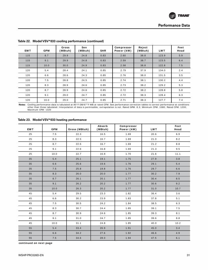
Notes: Cooling performance data is tabulated at 80°F DB/67°F WB at rated CFM. See performance correction tables to correct performance at conditions other than those tabulated. Interpolation of data is permissible; extrapolation is not. Rated GPM: 8.3; Minimum CFM: 1080; Rated CFM: 1200; Maximum CFM: 1320
Table 22. Model VSV*033 cooling performance (continued)
EWT GPMGross
(MBtuh)Sen
(MBtuh) SHRCompressor Power (kW)
Reject (MBtuh) LWT
FeetHead
Table 23. Model VSV*033 heating performance
EWT GPM Gross (MBtuh)Absorb
(MBtuh)Compressor Power (kW) LWT
FeetHead
25 7.5 22.3 16.5 1.69 20.6 6.9
25 8.3 22.5 16.7 1.69 21.0 8.2
25 8.7 22.5 16.7 1.69 21.2 8.8
25 9.1 22.6 16.8 1.69 21.3 9.5
25 10.0 22.7 16.9 1.70 21.6 11.1
35 5.4 25.1 19.1 1.75 27.9 3.8
35 6.6 25.6 19.6 1.76 29.1 5.4
35 7.5 25.8 19.8 1.76 29.7 6.6
35 8.3 26.0 20.0 1.77 30.2 7.9
35 8.7 26.1 20.1 1.77 30.4 8.5
35 9.1 26.2 20.2 1.77 30.6 9.2
35 10.0 26.3 20.2 1.77 31.0 10.7
45 5.4 29.5 23.3 1.82 36.4 3.6
45 6.6 30.2 23.9 1.83 37.8 5.1
45 7.5 30.5 24.2 1.84 38.5 6.3
45 8.3 30.7 24.4 1.85 39.1 7.5
45 8.7 30.9 24.6 1.85 39.3 8.1
45 9.1 31.0 24.7 1.85 39.6 8.8
45 10.0 31.1 24.8 1.85 40.0 10.2
55 5.4 33.4 26.9 1.91 45.0 3.4
55 6.6 34.2 27.6 1.92 46.6 4.9
55 7.5 34.6 28.0 1.94 47.5 6.1
continued on next page
WSHP-PRC026D-EN 31
Performance Data
55 8.3 35.0 28.4 1.94 48.2 7.2
55 8.7 35.1 28.5 1.95 48.4 7.8
55 9.1 35.3 28.7 1.95 48.7 8.4
55 10.0 35.5 28.8 1.95 49.2 9.8
65 5.4 37.7 30.9 2.00 53.6 3.3
65 6.6 38.7 31.8 2.02 55.4 4.6
65 7.5 39.3 32.4 2.03 56.4 5.8
65 8.3 39.7 32.7 2.04 57.1 6.8
65 8.7 39.9 32.9 2.05 57.4 7.4
65 9.1 40.1 33.1 2.05 57.7 8.0
65 10.0 40.4 33.4 2.06 58.3 9.3
75 5.4 42.3 35.1 2.11 62.0 3.1
75 6.6 43.5 36.2 2.14 64.0 4.4
75 7.5 44.1 36.8 2.15 65.2 5.5
75 8.3 44.7 37.3 2.17 66.0 6.5
75 8.7 44.9 37.5 2.17 66.4 7.1
75 9.1 45.2 37.8 2.18 66.7 7.6
75 10.0 45.5 38.0 2.19 67.4 8.9
85 5.4 47.1 39.5 2.23 70.4 2.9
85 6.6 48.7 41.0 2.27 72.6 4.2
85 7.5 49.4 41.6 2.29 73.9 5.2
85 8.3 50.1 42.2 2.31 74.8 6.2
85 8.7 50.4 42.5 2.31 75.2 6.8
85 9.1 50.6 42.7 2.32 75.6 7.3
85 10.0 51.1 43.1 2.33 76.4 8.6
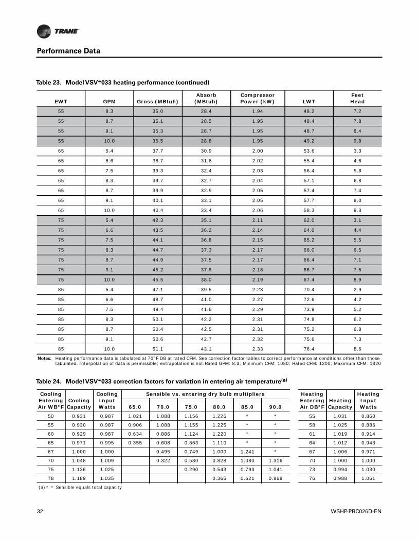
Notes: Heating performance data is tabulated at 70°F DB at rated CFM. See correction factor tables to correct performance at conditions other than those tabulated. Interpolation of data is permissible; extrapolation is not.Rated GPM: 8.3; Minimum CFM: 1080; Rated CFM: 1200; Maximum CFM: 1320
Table 23. Model VSV*033 heating performance (continued)
EWT GPM Gross (MBtuh)Absorb
(MBtuh)Compressor Power (kW) LWT
FeetHead
Table 24. Model VSV*033 correction factors for variation in entering air temperature(a)
Cooling Entering Air WB°F
Cooling Capacity
Cooling Input Watts
Sensible vs. entering dry bulb multipliers Heating Entering Air DB°F
Heating Capacity
Heating Input Watts65.0 70.0 75.0 80.0 85.0 90.0
50 0.931 0.987 1.021 1.088 1.156 1.226 * * 55 1.031 0.860
55 0.930 0.987 0.906 1.088 1.155 1.225 * * 58 1.025 0.886
60 0.929 0.987 0.634 0.886 1.124 1.220 * * 61 1.019 0.914
65 0.971 0.995 0.355 0.608 0.863 1.110 * * 64 1.012 0.943
67 1.000 1.000 0.495 0.749 1.000 1.241 * 67 1.006 0.971
70 1.048 1.009 0.322 0.580 0.828 1.080 1.316 70 1.000 1.000
75 1.136 1.025 0.290 0.543 0.793 1.041 73 0.994 1.030
78 1.189 1.035 0.365 0.621 0.868 76 0.988 1.061
(a) * = Sensible equals total capacity
32 WSHP-PRC026D-EN
Performance Data
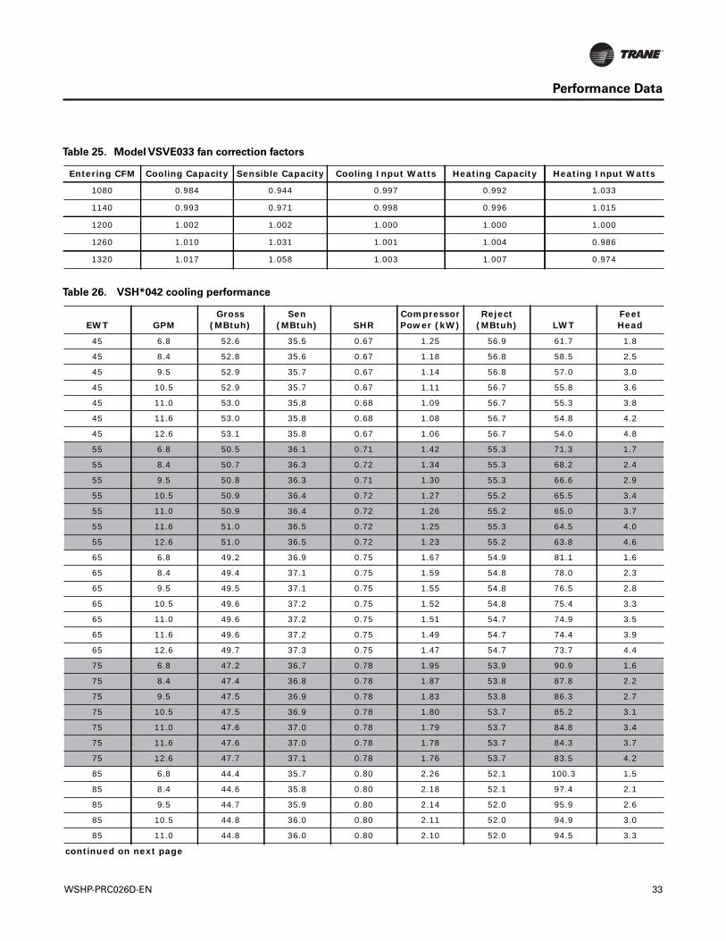
Table 25. Model VSVE033 fan correction factors
Entering CFM Cooling Capacity Sensible Capacity Cooling Input Watts Heating Capacity Heating Input Watts
1080 0.984 0.944 0.997 0.992 1.033
1140 0.993 0.971 0.998 0.996 1.015
1200 1.002 1.002 1.000 1.000 1.000
1260 1.010 1.031 1.001 1.004 0.986
1320 1.017 1.058 1.003 1.007 0.974
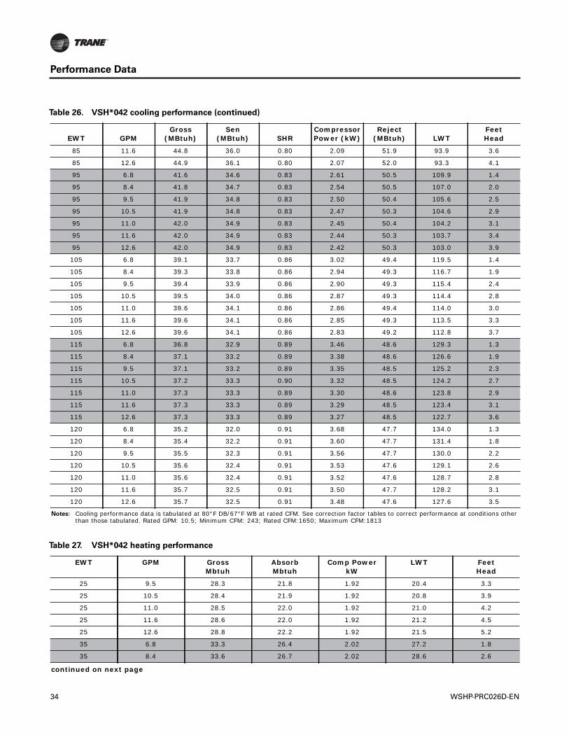
Table 26. VSH*042 cooling performance
EWT GPMGross
(MBtuh)Sen
(MBtuh) SHRCompressor Power (kW)
Reject (MBtuh) LWT
FeetHead
45 6.8 52.6 35.5 0.67 1.25 56.9 61.7 1.8
45 8.4 52.8 35.6 0.67 1.18 56.8 58.5 2.5
45 9.5 52.9 35.7 0.67 1.14 56.8 57.0 3.0
45 10.5 52.9 35.7 0.67 1.11 56.7 55.8 3.6
45 11.0 53.0 35.8 0.68 1.09 56.7 55.3 3.8
45 11.6 53.0 35.8 0.68 1.08 56.7 54.8 4.2
45 12.6 53.1 35.8 0.67 1.06 56.7 54.0 4.8
55 6.8 50.5 36.1 0.71 1.42 55.3 71.3 1.7
55 8.4 50.7 36.3 0.72 1.34 55.3 68.2 2.4
55 9.5 50.8 36.3 0.71 1.30 55.3 66.6 2.9
55 10.5 50.9 36.4 0.72 1.27 55.2 65.5 3.4
55 11.0 50.9 36.4 0.72 1.26 55.2 65.0 3.7
55 11.6 51.0 36.5 0.72 1.25 55.3 64.5 4.0
55 12.6 51.0 36.5 0.72 1.23 55.2 63.8 4.6
65 6.8 49.2 36.9 0.75 1.67 54.9 81.1 1.6
65 8.4 49.4 37.1 0.75 1.59 54.8 78.0 2.3
65 9.5 49.5 37.1 0.75 1.55 54.8 76.5 2.8
65 10.5 49.6 37.2 0.75 1.52 54.8 75.4 3.3
65 11.0 49.6 37.2 0.75 1.51 54.7 74.9 3.5
65 11.6 49.6 37.2 0.75 1.49 54.7 74.4 3.9
65 12.6 49.7 37.3 0.75 1.47 54.7 73.7 4.4
75 6.8 47.2 36.7 0.78 1.95 53.9 90.9 1.6
75 8.4 47.4 36.8 0.78 1.87 53.8 87.8 2.2
75 9.5 47.5 36.9 0.78 1.83 53.8 86.3 2.7
75 10.5 47.5 36.9 0.78 1.80 53.7 85.2 3.1
75 11.0 47.6 37.0 0.78 1.79 53.7 84.8 3.4
75 11.6 47.6 37.0 0.78 1.78 53.7 84.3 3.7
75 12.6 47.7 37.1 0.78 1.76 53.7 83.5 4.2
85 6.8 44.4 35.7 0.80 2.26 52.1 100.3 1.5
85 8.4 44.6 35.8 0.80 2.18 52.1 97.4 2.1
85 9.5 44.7 35.9 0.80 2.14 52.0 95.9 2.6
85 10.5 44.8 36.0 0.80 2.11 52.0 94.9 3.0
85 11.0 44.8 36.0 0.80 2.10 52.0 94.5 3.3
continued on next page
WSHP-PRC026D-EN 33
Performance Data
85 11.6 44.8 36.0 0.80 2.09 51.9 93.9 3.6
85 12.6 44.9 36.1 0.80 2.07 52.0 93.3 4.1
95 6.8 41.6 34.6 0.83 2.61 50.5 109.9 1.4
95 8.4 41.8 34.7 0.83 2.54 50.5 107.0 2.0
95 9.5 41.9 34.8 0.83 2.50 50.4 105.6 2.5
95 10.5 41.9 34.8 0.83 2.47 50.3 104.6 2.9
95 11.0 42.0 34.9 0.83 2.45 50.4 104.2 3.1
95 11.6 42.0 34.9 0.83 2.44 50.3 103.7 3.4
95 12.6 42.0 34.9 0.83 2.42 50.3 103.0 3.9
105 6.8 39.1 33.7 0.86 3.02 49.4 119.5 1.4
105 8.4 39.3 33.8 0.86 2.94 49.3 116.7 1.9
105 9.5 39.4 33.9 0.86 2.90 49.3 115.4 2.4
105 10.5 39.5 34.0 0.86 2.87 49.3 114.4 2.8
105 11.0 39.6 34.1 0.86 2.86 49.4 114.0 3.0
105 11.6 39.6 34.1 0.86 2.85 49.3 113.5 3.3
105 12.6 39.6 34.1 0.86 2.83 49.2 112.8 3.7
115 6.8 36.8 32.9 0.89 3.46 48.6 129.3 1.3
115 8.4 37.1 33.2 0.89 3.38 48.6 126.6 1.9
115 9.5 37.1 33.2 0.89 3.35 48.5 125.2 2.3
115 10.5 37.2 33.3 0.90 3.32 48.5 124.2 2.7
115 11.0 37.3 33.3 0.89 3.30 48.6 123.8 2.9
115 11.6 37.3 33.3 0.89 3.29 48.5 123.4 3.1
115 12.6 37.3 33.3 0.89 3.27 48.5 122.7 3.6
120 6.8 35.2 32.0 0.91 3.68 47.7 134.0 1.3
120 8.4 35.4 32.2 0.91 3.60 47.7 131.4 1.8
120 9.5 35.5 32.3 0.91 3.56 47.7 130.0 2.2
120 10.5 35.6 32.4 0.91 3.53 47.6 129.1 2.6
120 11.0 35.6 32.4 0.91 3.52 47.6 128.7 2.8
120 11.6 35.7 32.5 0.91 3.50 47.7 128.2 3.1
120 12.6 35.7 32.5 0.91 3.48 47.6 127.6 3.5
Notes: Cooling performance data is tabulated at 80°F DB/67°F WB at rated CFM. See correction factor tables to correct performance at conditions other than those tabulated. Rated GPM: 10.5; Minimum CFM: 243; Rated CFM:1650; Maximum CFM:1813
Table 26. VSH*042 cooling performance (continued)
EWT GPMGross
(MBtuh)Sen
(MBtuh) SHRCompressor Power (kW)
Reject (MBtuh) LWT
FeetHead
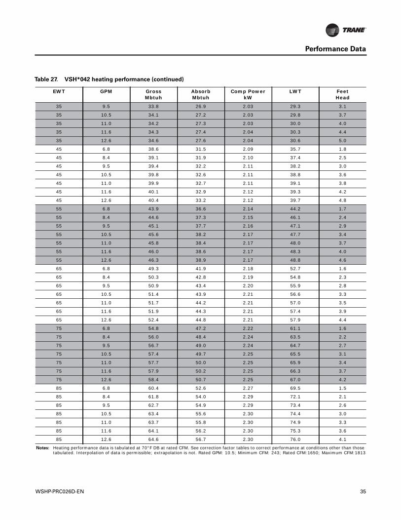
Table 27. VSH*042 heating performance
EWT GPM GrossMbtuh
AbsorbMbtuh
Comp PowerkW
LWT FeetHead
25 9.5 28.3 21.8 1.92 20.4 3.3
25 10.5 28.4 21.9 1.92 20.8 3.9
25 11.0 28.5 22.0 1.92 21.0 4.2
25 11.6 28.6 22.0 1.92 21.2 4.5
25 12.6 28.8 22.2 1.92 21.5 5.2
35 6.8 33.3 26.4 2.02 27.2 1.8
35 8.4 33.6 26.7 2.02 28.6 2.6
continued on next page
34 WSHP-PRC026D-EN
Performance Data
35 9.5 33.8 26.9 2.03 29.3 3.1
35 10.5 34.1 27.2 2.03 29.8 3.7
35 11.0 34.2 27.3 2.03 30.0 4.0
35 11.6 34.3 27.4 2.04 30.3 4.4
35 12.6 34.6 27.6 2.04 30.6 5.0
45 6.8 38.6 31.5 2.09 35.7 1.8
45 8.4 39.1 31.9 2.10 37.4 2.5
45 9.5 39.4 32.2 2.11 38.2 3.0
45 10.5 39.8 32.6 2.11 38.8 3.6
45 11.0 39.9 32.7 2.11 39.1 3.8
45 11.6 40.1 32.9 2.12 39.3 4.2
45 12.6 40.4 33.2 2.12 39.7 4.8
55 6.8 43.9 36.6 2.14 44.2 1.7
55 8.4 44.6 37.3 2.15 46.1 2.4
55 9.5 45.1 37.7 2.16 47.1 2.9
55 10.5 45.6 38.2 2.17 47.7 3.4
55 11.0 45.8 38.4 2.17 48.0 3.7
55 11.6 46.0 38.6 2.17 48.3 4.0
55 12.6 46.3 38.9 2.17 48.8 4.6
65 6.8 49.3 41.9 2.18 52.7 1.6
65 8.4 50.3 42.8 2.19 54.8 2.3
65 9.5 50.9 43.4 2.20 55.9 2.8
65 10.5 51.4 43.9 2.21 56.6 3.3
65 11.0 51.7 44.2 2.21 57.0 3.5
65 11.6 51.9 44.3 2.21 57.4 3.9
65 12.6 52.4 44.8 2.21 57.9 4.4
75 6.8 54.8 47.2 2.22 61.1 1.6
75 8.4 56.0 48.4 2.24 63.5 2.2
75 9.5 56.7 49.0 2.24 64.7 2.7
75 10.5 57.4 49.7 2.25 65.5 3.1
75 11.0 57.7 50.0 2.25 65.9 3.4
75 11.6 57.9 50.2 2.25 66.3 3.7
75 12.6 58.4 50.7 2.25 67.0 4.2
85 6.8 60.4 52.6 2.27 69.5 1.5
85 8.4 61.8 54.0 2.29 72.1 2.1
85 9.5 62.7 54.9 2.29 73.4 2.6
85 10.5 63.4 55.6 2.30 74.4 3.0
85 11.0 63.7 55.8 2.30 74.9 3.3
85 11.6 64.1 56.2 2.30 75.3 3.6
85 12.6 64.6 56.7 2.30 76.0 4.1
Notes: Heating performance data is tabulated at 70°F DB at rated CFM. See correction factor tables to correct performance at conditions other than those tabulated. Interpolation of data is permissible; extrapolation is not. Rated GPM: 10.5; Minimum CFM: 243; Rated CFM:1650; Maximum CFM:1813
Table 27. VSH*042 heating performance (continued)
EWT GPM GrossMbtuh
AbsorbMbtuh
Comp PowerkW
LWT FeetHead
WSHP-PRC026D-EN 35
Performance Data
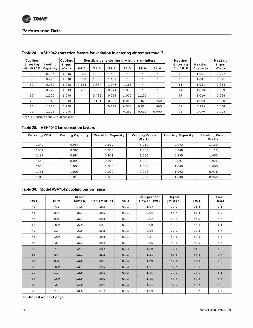
Table 28. VSH*042 correction factors for variation in entering air temperature(a)
Cooling Entering Air WB°F
Cooling Capacity
Cooling Input Watts
Sensible vs. entering dry bulb multipliers Heating Entering Air DB°F
Heating Capacity
Heating Input Watts65.0 70.0 75.0 80.0 85.0 90.0
50 0.954 1.006 0.956 1.028 * * * * 55 1.051 0.777
55 0.946 1.008 0.859 1.006 1.101 * * * 58 1.041 0.821
60 0.950 1.008 0.623 0.874 1.046 1.166 * * 61 1.031 0.864
65 0.979 1.003 0.225 0.603 0.874 1.070 * * 64 1.020 0.909
67 1.000 1.000 0.452 0.768 1.000 1.171 * 67 1.010 0.954
70 1.040 0.993 0.181 0.568 0.858 1.075 1.240 70 1.000 1.000
75 1.133 0.978 0.123 0.518 0.824 1.060 73 0.989 1.046
78 1.206 0.966 0.253 0.615 0.900 76 0.979 1.094
(a) * = Sensible equals total capacity
Table 29. VSH*042 fan correction factors
Entering CFM Cooling Capacity Sensible Capacity Cooling Comp Watts
Heating Capacity Heating Comp Watts
1243 0.954 0.853 1.010 0.983 1.159
1324 0.965 0.883 1.007 0.988 1.119
1487 0.984 0.941 1.004 0.995 1.053
1569 0.992 0.970 1.002 0.997 1.025
1650 1.000 1.000 1.000 1.000 1.000
1731 1.007 1.029 0.998 1.003 0.978
1813 1.013 1.056 0.997 1.008 0.959
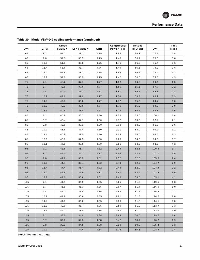
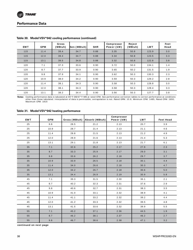
Table 30. Model VSV*042 cooling performance
EWT GPMGross
(MBtuh) Sen (MBtuh) SHRCompressor Power (kW)
Reject (MBtuh) LWT
FeetHead
45 7.1 54.8 38.9 0.71 1.03 58.3 61.4 2.1
45 8.7 55.4 39.3 0.71 0.96 58.7 58.5 2.9
45 9.8 55.7 39.5 0.71 0.92 58.8 57.0 3.5
45 10.9 55.9 39.7 0.71 0.90 59.0 55.8 4.1
45 11.4 56.0 39.8 0.71 0.88 59.0 55.4 4.4
45 12.0 56.1 39.8 0.71 0.87 59.1 54.9 4.8
45 13.1 56.2 39.9 0.71 0.86 59.1 54.0 5.5
55 7.1 52.7 38.5 0.73 1.30 57.1 71.1 1.9
55 8.7 53.3 38.9 0.73 1.23 57.5 68.2 2.7
55 9.8 53.5 39.1 0.73 1.20 57.6 66.8 3.2
55 10.9 53.7 39.2 0.73 1.17 57.7 65.6 3.8
55 11.4 53.8 39.3 0.73 1.16 57.8 65.1 4.1
55 12.0 53.9 39.3 0.73 1.15 57.8 64.6 4.5
55 13.1 54.0 39.4 0.73 1.14 57.9 63.8 5.2
65 7.1 50.5 37.9 0.75 1.59 55.9 80.7 1.7
continued on next page
36 WSHP-PRC026D-EN
Performance Data
65 8.7 51.1 38.3 0.75 1.52 56.3 77.9 2.4
65 9.8 51.3 38.5 0.75 1.48 56.4 76.5 3.0
65 10.9 51.5 38.6 0.75 1.46 56.5 75.4 3.6
65 11.4 51.6 38.7 0.75 1.45 56.5 74.9 3.8
65 12.0 51.6 38.7 0.75 1.44 56.5 74.4 4.2
65 13.1 51.8 38.9 0.75 1.42 56.6 73.6 4.9
75 7.1 48.2 37.1 0.77 1.92 54.8 90.4 1.6
75 8.7 48.8 37.6 0.77 1.85 55.1 87.7 2.2
75 9.8 49.0 37.7 0.77 1.81 55.2 86.3 2.8
75 10.9 49.2 37.9 0.77 1.78 55.3 85.1 3.3
75 11.4 49.3 38.0 0.77 1.77 55.3 84.7 3.6
75 12.0 49.3 38.0 0.77 1.76 55.3 84.2 3.9
75 13.1 49.4 38.0 0.77 1.74 55.4 83.5 4.6
85 7.1 45.9 36.7 0.80 2.25 53.6 100.1 1.4
85 8.7 46.4 37.1 0.80 2.17 53.8 97.4 2.1
85 9.8 46.6 37.3 0.80 2.13 53.9 96.0 2.6
85 10.9 46.8 37.4 0.80 2.11 54.0 94.9 3.1
85 11.4 46.9 37.5 0.80 2.09 54.0 94.5 3.3
85 12.0 46.9 37.5 0.80 2.08 54.0 94.0 3.7
85 13.1 47.0 37.6 0.80 2.06 54.0 93.2 4.3
95 7.1 43.5 35.7 0.82 2.64 52.5 109.8 1.3
95 8.7 44.0 36.1 0.82 2.56 52.7 107.1 1.9
95 9.8 44.2 36.2 0.82 2.52 52.8 105.8 2.4
95 10.9 44.4 36.4 0.82 2.49 52.9 104.7 2.9
95 11.4 44.4 36.4 0.82 2.48 52.9 104.3 3.2
95 12.0 44.5 36.5 0.82 2.47 52.9 103.8 3.5
95 13.1 44.6 36.6 0.82 2.45 53.0 103.1 4.1
105 7.1 41.1 34.9 0.85 3.05 51.5 119.5 1.3
105 8.7 41.5 35.3 0.85 2.97 51.7 116.9 1.9
105 9.8 41.7 35.4 0.85 2.94 51.7 115.6 2.3
105 10.9 41.9 35.6 0.85 2.91 51.8 114.5 2.8
105 11.4 41.9 35.6 0.85 2.90 51.8 114.1 3.0
105 12.0 42.0 35.7 0.85 2.89 51.9 113.7 3.3
105 13.1 42.1 35.8 0.85 2.87 51.9 112.9 3.9
115 7.1 38.6 34.0 0.88 3.49 50.5 129.2 1.4
115 8.7 39.0 34.3 0.88 3.42 50.7 126.7 1.9
115 9.8 39.2 34.5 0.88 3.39 50.8 125.4 2.3
115 10.9 39.3 34.6 0.88 3.36 50.8 124.3 2.8
continued on next page
Table 30. Model VSV*042 cooling performance (continued)
EWT GPMGross
(MBtuh) Sen (MBtuh) SHRCompressor Power (kW)
Reject (MBtuh) LWT
FeetHead
WSHP-PRC026D-EN 37
Performance Data
115 11.4 39.4 34.7 0.88 3.35 50.8 123.9 3.0
115 12.0 39.4 34.7 0.88 3.34 50.8 123.5 3.3
115 13.1 39.5 34.8 0.88 3.32 50.8 122.8 3.8
120 7.1 37.3 33.6 0.90 3.72 50.0 134.1 1.4
120 8.7 37.7 33.9 0.90 3.65 50.2 131.5 1.9
120 9.8 37.9 34.1 0.90 3.62 50.3 130.3 2.3
120 10.9 38.0 34.2 0.90 3.59 50.3 129.2 2.8
120 11.4 38.1 34.3 0.90 3.58 50.3 128.8 3.0
120 12.0 38.1 34.3 0.90 3.58 50.3 128.4 3.3
120 13.1 38.2 34.4 0.90 3.56 50.3 127.7 3.8
Notes: Cooling performance data is tabulated at 80°F DB/67°F WB at rated CFM. See performance correction tables to correct performance at conditions other than those tabulated. Interpolation of data is permissible; extrapolation is not. Rated GPM: 10.9; Minimum CFM: 1485; Rated CFM: 1650; Maximum CFM: 1815
Table 30. Model VSV*042 cooling performance (continued)
EWT GPMGross
(MBtuh) Sen (MBtuh) SHRCompressor Power (kW)
Reject (MBtuh) LWT
FeetHead
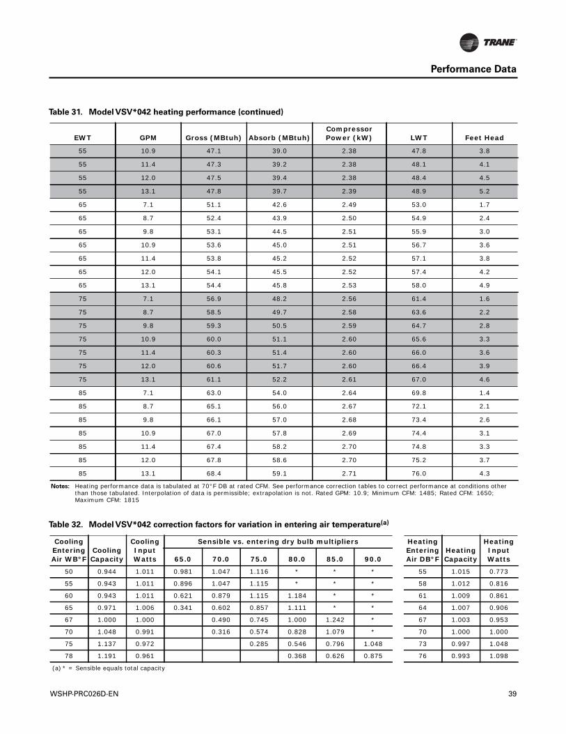
Table 31. Model VSV*042 heating performance
EWT GPM Gross (MBtuh) Absorb (MBtuh)Compressor Power (kW) LWT Feet Head
25 9.8 28.5 21.2 2.13 20.7 3.9
25 10.9 28.7 21.4 2.13 21.1 4.6
25 11.4 28.8 21.5 2.13 21.2 4.9
25 12.0 28.9 21.6 2.13 21.4 5.3
25 13.1 29.1 21.8 2.13 21.7 6.1
35 7.1 32.6 25.2 2.17 27.9 2.3
35 8.7 33.3 25.9 2.17 29.0 3.1
35 9.8 33.6 26.2 2.18 29.7 3.7
35 10.9 33.9 26.5 2.18 30.1 4.4
35 11.4 34.0 26.6 2.18 30.3 4.7
35 12.0 34.2 26.7 2.18 30.6 5.0
35 13.1 34.4 26.9 2.19 30.9 5.8
45 7.1 39.3 31.5 2.30 36.1 2.1
45 8.7 40.2 32.3 2.31 37.6 2.9
45 9.8 40.6 32.7 2.31 38.3 3.5
45 10.9 41.0 33.1 2.32 38.9 4.1
45 11.4 41.1 33.2 2.32 39.2 4.4
45 12.0 41.2 33.3 2.32 39.5 4.8
45 13.1 41.5 33.6 2.32 39.9 5.5
55 7.1 45.2 37.1 2.36 44.5 1.9
55 8.7 46.2 38.1 2.37 46.2 2.7
55 9.8 46.7 38.6 2.38 47.1 3.2
continued on next page
38 WSHP-PRC026D-EN
Performance Data
55 10.9 47.1 39.0 2.38 47.8 3.8
55 11.4 47.3 39.2 2.38 48.1 4.1
55 12.0 47.5 39.4 2.38 48.4 4.5
55 13.1 47.8 39.7 2.39 48.9 5.2
65 7.1 51.1 42.6 2.49 53.0 1.7
65 8.7 52.4 43.9 2.50 54.9 2.4
65 9.8 53.1 44.5 2.51 55.9 3.0
65 10.9 53.6 45.0 2.51 56.7 3.6
65 11.4 53.8 45.2 2.52 57.1 3.8
65 12.0 54.1 45.5 2.52 57.4 4.2
65 13.1 54.4 45.8 2.53 58.0 4.9
75 7.1 56.9 48.2 2.56 61.4 1.6
75 8.7 58.5 49.7 2.58 63.6 2.2
75 9.8 59.3 50.5 2.59 64.7 2.8
75 10.9 60.0 51.1 2.60 65.6 3.3
75 11.4 60.3 51.4 2.60 66.0 3.6
75 12.0 60.6 51.7 2.60 66.4 3.9
75 13.1 61.1 52.2 2.61 67.0 4.6
85 7.1 63.0 54.0 2.64 69.8 1.4
85 8.7 65.1 56.0 2.67 72.1 2.1
85 9.8 66.1 57.0 2.68 73.4 2.6
85 10.9 67.0 57.8 2.69 74.4 3.1
85 11.4 67.4 58.2 2.70 74.8 3.3
85 12.0 67.8 58.6 2.70 75.2 3.7
85 13.1 68.4 59.1 2.71 76.0 4.3
Notes: Heating performance data is tabulated at 70°F DB at rated CFM. See performance correction tables to correct performance at conditions other than those tabulated. Interpolation of data is permissible; extrapolation is not. Rated GPM: 10.9; Minimum CFM: 1485; Rated CFM: 1650; Maximum CFM: 1815
Table 31. Model VSV*042 heating performance (continued)
EWT GPM Gross (MBtuh) Absorb (MBtuh)Compressor Power (kW) LWT Feet Head
Table 32. Model VSV*042 correction factors for variation in entering air temperature(a)
Cooling Entering Air WB°F
Cooling Capacity
Cooling Input Watts
Sensible vs. entering dry bulb multipliers Heating Entering Air DB°F
Heating Capacity
Heating Input Watts65.0 70.0 75.0 80.0 85.0 90.0
50 0.944 1.011 0.981 1.047 1.116 * * * 55 1.015 0.773
55 0.943 1.011 0.896 1.047 1.115 * * * 58 1.012 0.816
60 0.943 1.011 0.621 0.879 1.115 1.184 * * 61 1.009 0.861
65 0.971 1.006 0.341 0.602 0.857 1.111 * * 64 1.007 0.906
67 1.000 1.000 0.490 0.745 1.000 1.242 * 67 1.003 0.953
70 1.048 0.991 0.316 0.574 0.828 1.079 * 70 1.000 1.000
75 1.137 0.972 0.285 0.546 0.796 1.048 73 0.997 1.048
78 1.191 0.961 0.368 0.626 0.875 76 0.993 1.098
(a) * = Sensible equals total capacity
WSHP-PRC026D-EN 39
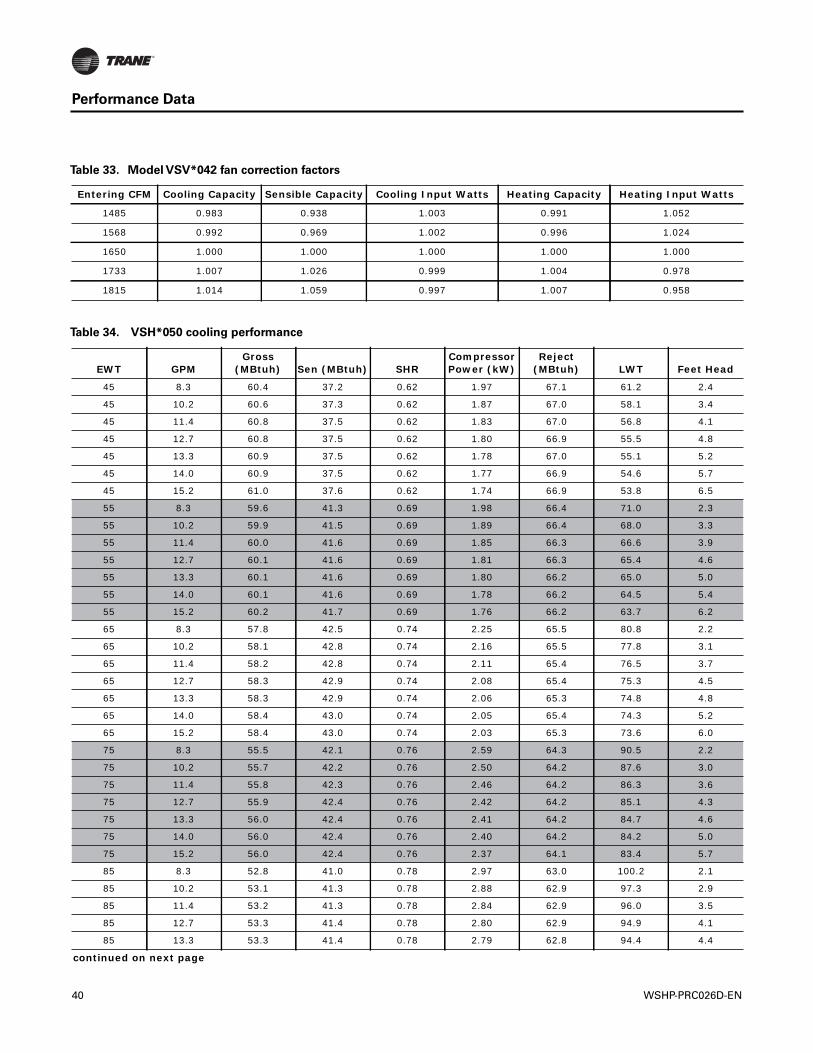
Performance Data
Table 33. Model VSV*042 fan correction factors
Entering CFM Cooling Capacity Sensible Capacity Cooling Input Watts Heating Capacity Heating Input Watts
1485 0.983 0.938 1.003 0.991 1.052
1568 0.992 0.969 1.002 0.996 1.024
1650 1.000 1.000 1.000 1.000 1.000
1733 1.007 1.026 0.999 1.004 0.978
1815 1.014 1.059 0.997 1.007 0.958
Table 34. VSH*050 cooling performance
EWT GPMGross
(MBtuh) Sen (MBtuh) SHRCompressor Power (kW)
Reject (MBtuh) LWT Feet Head
45 8.3 60.4 37.2 0.62 1.97 67.1 61.2 2.4
45 10.2 60.6 37.3 0.62 1.87 67.0 58.1 3.4
45 11.4 60.8 37.5 0.62 1.83 67.0 56.8 4.1
45 12.7 60.8 37.5 0.62 1.80 66.9 55.5 4.8
45 13.3 60.9 37.5 0.62 1.78 67.0 55.1 5.2
45 14.0 60.9 37.5 0.62 1.77 66.9 54.6 5.7
45 15.2 61.0 37.6 0.62 1.74 66.9 53.8 6.5
55 8.3 59.6 41.3 0.69 1.98 66.4 71.0 2.3
55 10.2 59.9 41.5 0.69 1.89 66.4 68.0 3.3
55 11.4 60.0 41.6 0.69 1.85 66.3 66.6 3.9
55 12.7 60.1 41.6 0.69 1.81 66.3 65.4 4.6
55 13.3 60.1 41.6 0.69 1.80 66.2 65.0 5.0
55 14.0 60.1 41.6 0.69 1.78 66.2 64.5 5.4
55 15.2 60.2 41.7 0.69 1.76 66.2 63.7 6.2
65 8.3 57.8 42.5 0.74 2.25 65.5 80.8 2.2
65 10.2 58.1 42.8 0.74 2.16 65.5 77.8 3.1
65 11.4 58.2 42.8 0.74 2.11 65.4 76.5 3.7
65 12.7 58.3 42.9 0.74 2.08 65.4 75.3 4.5
65 13.3 58.3 42.9 0.74 2.06 65.3 74.8 4.8
65 14.0 58.4 43.0 0.74 2.05 65.4 74.3 5.2
65 15.2 58.4 43.0 0.74 2.03 65.3 73.6 6.0
75 8.3 55.5 42.1 0.76 2.59 64.3 90.5 2.2
75 10.2 55.7 42.2 0.76 2.50 64.2 87.6 3.0
75 11.4 55.8 42.3 0.76 2.46 64.2 86.3 3.6
75 12.7 55.9 42.4 0.76 2.42 64.2 85.1 4.3
75 13.3 56.0 42.4 0.76 2.41 64.2 84.7 4.6
75 14.0 56.0 42.4 0.76 2.40 64.2 84.2 5.0
75 15.2 56.0 42.4 0.76 2.37 64.1 83.4 5.7
85 8.3 52.8 41.0 0.78 2.97 63.0 100.2 2.1
85 10.2 53.1 41.3 0.78 2.88 62.9 97.3 2.9
85 11.4 53.2 41.3 0.78 2.84 62.9 96.0 3.5
85 12.7 53.3 41.4 0.78 2.80 62.9 94.9 4.1
85 13.3 53.3 41.4 0.78 2.79 62.8 94.4 4.4
continued on next page
40 WSHP-PRC026D-EN
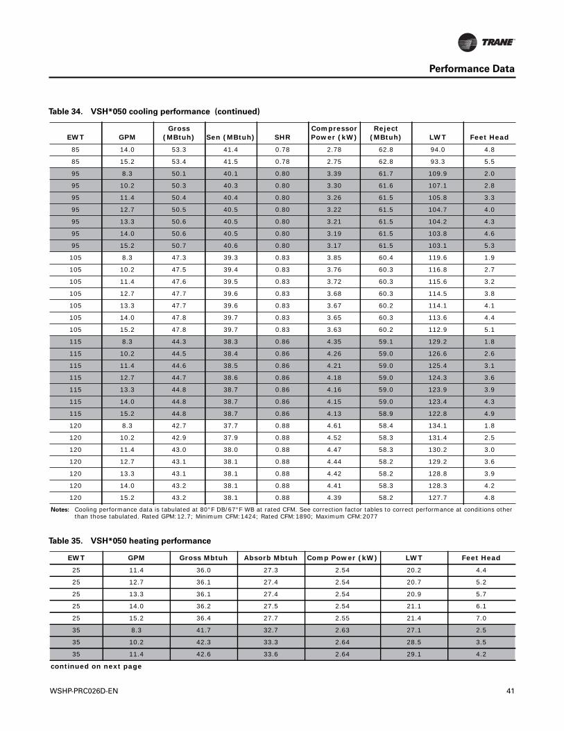
Performance Data
85 14.0 53.3 41.4 0.78 2.78 62.8 94.0 4.8
85 15.2 53.4 41.5 0.78 2.75 62.8 93.3 5.5
95 8.3 50.1 40.1 0.80 3.39 61.7 109.9 2.0
95 10.2 50.3 40.3 0.80 3.30 61.6 107.1 2.8
95 11.4 50.4 40.4 0.80 3.26 61.5 105.8 3.3
95 12.7 50.5 40.5 0.80 3.22 61.5 104.7 4.0
95 13.3 50.6 40.5 0.80 3.21 61.5 104.2 4.3
95 14.0 50.6 40.5 0.80 3.19 61.5 103.8 4.6
95 15.2 50.7 40.6 0.80 3.17 61.5 103.1 5.3
105 8.3 47.3 39.3 0.83 3.85 60.4 119.6 1.9
105 10.2 47.5 39.4 0.83 3.76 60.3 116.8 2.7
105 11.4 47.6 39.5 0.83 3.72 60.3 115.6 3.2
105 12.7 47.7 39.6 0.83 3.68 60.3 114.5 3.8
105 13.3 47.7 39.6 0.83 3.67 60.2 114.1 4.1
105 14.0 47.8 39.7 0.83 3.65 60.3 113.6 4.4
105 15.2 47.8 39.7 0.83 3.63 60.2 112.9 5.1
115 8.3 44.3 38.3 0.86 4.35 59.1 129.2 1.8
115 10.2 44.5 38.4 0.86 4.26 59.0 126.6 2.6
115 11.4 44.6 38.5 0.86 4.21 59.0 125.4 3.1
115 12.7 44.7 38.6 0.86 4.18 59.0 124.3 3.6
115 13.3 44.8 38.7 0.86 4.16 59.0 123.9 3.9
115 14.0 44.8 38.7 0.86 4.15 59.0 123.4 4.3
115 15.2 44.8 38.7 0.86 4.13 58.9 122.8 4.9
120 8.3 42.7 37.7 0.88 4.61 58.4 134.1 1.8
120 10.2 42.9 37.9 0.88 4.52 58.3 131.4 2.5
120 11.4 43.0 38.0 0.88 4.47 58.3 130.2 3.0
120 12.7 43.1 38.1 0.88 4.44 58.2 129.2 3.6
120 13.3 43.1 38.1 0.88 4.42 58.2 128.8 3.9
120 14.0 43.2 38.1 0.88 4.41 58.3 128.3 4.2
120 15.2 43.2 38.1 0.88 4.39 58.2 127.7 4.8
Notes: Cooling performance data is tabulated at 80°F DB/67°F WB at rated CFM. See correction factor tables to correct performance at conditions other than those tabulated. Rated GPM:12.7; Minimum CFM:1424; Rated CFM:1890; Maximum CFM:2077
Table 34. VSH*050 cooling performance (continued)
EWT GPMGross
(MBtuh) Sen (MBtuh) SHRCompressor Power (kW)
Reject (MBtuh) LWT Feet Head
Table 35. VSH*050 heating performance
EWT GPM Gross Mbtuh Absorb Mbtuh Comp Power (kW) LWT Feet Head
25 11.4 36.0 27.3 2.54 20.2 4.4
25 12.7 36.1 27.4 2.54 20.7 5.2
25 13.3 36.1 27.4 2.54 20.9 5.7
25 14.0 36.2 27.5 2.54 21.1 6.1
25 15.2 36.4 27.7 2.55 21.4 7.0
35 8.3 41.7 32.7 2.63 27.1 2.5
35 10.2 42.3 33.3 2.64 28.5 3.5
35 11.4 42.6 33.6 2.64 29.1 4.2
continued on next page
WSHP-PRC026D-EN 41
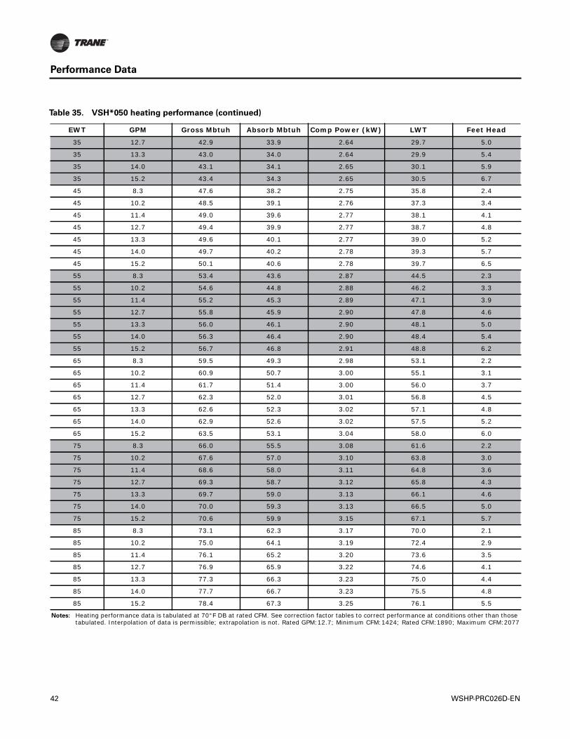
Performance Data
35 12.7 42.9 33.9 2.64 29.7 5.0
35 13.3 43.0 34.0 2.64 29.9 5.4
35 14.0 43.1 34.1 2.65 30.1 5.9
35 15.2 43.4 34.3 2.65 30.5 6.7
45 8.3 47.6 38.2 2.75 35.8 2.4
45 10.2 48.5 39.1 2.76 37.3 3.4
45 11.4 49.0 39.6 2.77 38.1 4.1
45 12.7 49.4 39.9 2.77 38.7 4.8
45 13.3 49.6 40.1 2.77 39.0 5.2
45 14.0 49.7 40.2 2.78 39.3 5.7
45 15.2 50.1 40.6 2.78 39.7 6.5
55 8.3 53.4 43.6 2.87 44.5 2.3
55 10.2 54.6 44.8 2.88 46.2 3.3
55 11.4 55.2 45.3 2.89 47.1 3.9
55 12.7 55.8 45.9 2.90 47.8 4.6
55 13.3 56.0 46.1 2.90 48.1 5.0
55 14.0 56.3 46.4 2.90 48.4 5.4
55 15.2 56.7 46.8 2.91 48.8 6.2
65 8.3 59.5 49.3 2.98 53.1 2.2
65 10.2 60.9 50.7 3.00 55.1 3.1
65 11.4 61.7 51.4 3.00 56.0 3.7
65 12.7 62.3 52.0 3.01 56.8 4.5
65 13.3 62.6 52.3 3.02 57.1 4.8
65 14.0 62.9 52.6 3.02 57.5 5.2
65 15.2 63.5 53.1 3.04 58.0 6.0
75 8.3 66.0 55.5 3.08 61.6 2.2
75 10.2 67.6 57.0 3.10 63.8 3.0
75 11.4 68.6 58.0 3.11 64.8 3.6
75 12.7 69.3 58.7 3.12 65.8 4.3
75 13.3 69.7 59.0 3.13 66.1 4.6
75 14.0 70.0 59.3 3.13 66.5 5.0
75 15.2 70.6 59.9 3.15 67.1 5.7
85 8.3 73.1 62.3 3.17 70.0 2.1
85 10.2 75.0 64.1 3.19 72.4 2.9
85 11.4 76.1 65.2 3.20 73.6 3.5
85 12.7 76.9 65.9 3.22 74.6 4.1
85 13.3 77.3 66.3 3.23 75.0 4.4
85 14.0 77.7 66.7 3.23 75.5 4.8
85 15.2 78.4 67.3 3.25 76.1 5.5
Notes: Heating performance data is tabulated at 70°F DB at rated CFM. See correction factor tables to correct performance at conditions other than those tabulated. Interpolation of data is permissible; extrapolation is not. Rated GPM:12.7; Minimum CFM:1424; Rated CFM:1890; Maximum CFM:2077
Table 35. VSH*050 heating performance (continued)
EWT GPM Gross Mbtuh Absorb Mbtuh Comp Power (kW) LWT Feet Head
42 WSHP-PRC026D-EN
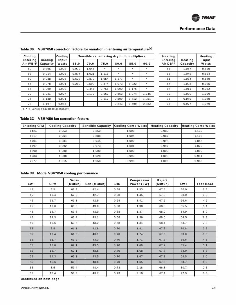
Performance Data
Table 36. VSH*050 correction factors for variation in entering air temperature(a)
Cooling Entering Air WB°F
Cooling Capacity
Cooling Input Watts
Sensible vs. entering dry bulb multipliers Heating Entering Air DB°F
Heating Capacity
Heating Input Watts65.0 70.0 75.0 80.0 85.0 90.0
50 0.896 1.003 0.979 1.045 * * * * 55 1.057 0.820
55 0.914 1.003 0.874 1.021 1.115 * * * 58 1.045 0.854
60 0.938 1.003 0.622 0.879 1.054 1.177 * * 61 1.034 0.889
65 0.978 1.001 0.210 0.599 0.874 1.073 1.222 * 64 1.023 0.925
67 1.000 1.000 0.446 0.765 1.000 1.176 * 67 1.011 0.962
70 1.041 0.997 0.172 0.562 0.853 1.074 1.245 70 1.000 1.000
75 1.130 0.991 0.117 0.509 0.812 1.051 73 0.989 1.039
78 1.197 0.986 0.243 0.599 0.882 76 0.977 1.079
(a) * = Sensible equals total capacity
Table 37. VSH*050 fan correction factors
Entering CFM Cooling Capacity Sensible Capacity Cooling Comp Watts Heating Capacity Heating Comp Watts
1424 0.953 0.860 1.005 0.980 1.136
1517 0.964 0.888 1.004 0.987 1.103
1704 0.984 0.945 1.002 0.995 1.046
1797 0.992 0.973 1.001 0.997 1.022
1890 1.000 1.000 1.000 1.000 1.000
1983 1.008 1.028 0.999 1.003 0.981
2077 1.015 1.058 0.998 1.006 0.963
Table 38. Model VSV*050 cooling performance
EWT GPMGross
(MBtuh) Sen (MBtuh) SHRCompressor Power (kW)
Reject (MBtuh) LWT Feet Head
45 8.5 62.3 42.4 0.68 1.53 67.5 60.9 2.8
45 10.4 62.8 42.7 0.68 1.45 67.8 58.0 3.8
45 11.7 63.1 42.9 0.68 1.41 67.9 56.6 4.6
45 13.0 63.3 43.0 0.68 1.38 68.0 55.5 5.4
45 13.7 63.3 43.0 0.68 1.37 68.0 54.9 5.9
45 14.3 63.4 43.1 0.68 1.36 68.0 54.5 6.3
45 15.6 63.5 43.2 0.68 1.34 68.1 53.7 7.3
55 8.5 61.1 42.8 0.70 1.81 67.3 70.8 2.6
55 10.4 61.6 43.1 0.70 1.74 67.5 68.0 3.5
55 11.7 61.9 43.3 0.70 1.71 67.7 66.6 4.3
55 13.0 62.1 43.5 0.70 1.69 67.9 65.4 5.1
55 13.7 62.1 43.5 0.70 1.68 67.8 64.9 5.6
55 14.3 62.2 43.5 0.70 1.67 67.9 64.5 6.0
55 15.6 62.3 43.6 0.70 1.65 67.9 63.7 6.9
65 8.5 59.4 43.4 0.73 2.18 66.8 80.7 2.3
65 10.4 59.9 43.7 0.73 2.10 67.1 77.9 3.3
continued on next page
WSHP-PRC026D-EN 43
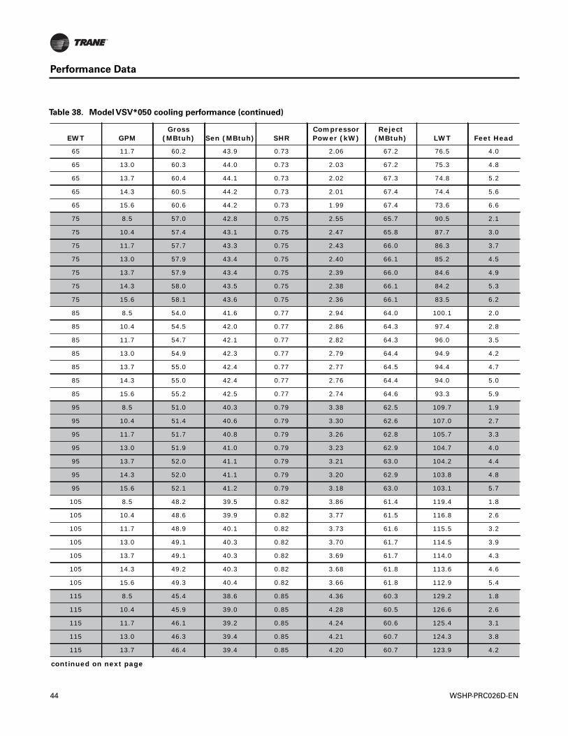
Performance Data
65 11.7 60.2 43.9 0.73 2.06 67.2 76.5 4.0
65 13.0 60.3 44.0 0.73 2.03 67.2 75.3 4.8
65 13.7 60.4 44.1 0.73 2.02 67.3 74.8 5.2
65 14.3 60.5 44.2 0.73 2.01 67.4 74.4 5.6
65 15.6 60.6 44.2 0.73 1.99 67.4 73.6 6.6
75 8.5 57.0 42.8 0.75 2.55 65.7 90.5 2.1
75 10.4 57.4 43.1 0.75 2.47 65.8 87.7 3.0
75 11.7 57.7 43.3 0.75 2.43 66.0 86.3 3.7
75 13.0 57.9 43.4 0.75 2.40 66.1 85.2 4.5
75 13.7 57.9 43.4 0.75 2.39 66.0 84.6 4.9
75 14.3 58.0 43.5 0.75 2.38 66.1 84.2 5.3
75 15.6 58.1 43.6 0.75 2.36 66.1 83.5 6.2
85 8.5 54.0 41.6 0.77 2.94 64.0 100.1 2.0
85 10.4 54.5 42.0 0.77 2.86 64.3 97.4 2.8
85 11.7 54.7 42.1 0.77 2.82 64.3 96.0 3.5
85 13.0 54.9 42.3 0.77 2.79 64.4 94.9 4.2
85 13.7 55.0 42.4 0.77 2.77 64.5 94.4 4.7
85 14.3 55.0 42.4 0.77 2.76 64.4 94.0 5.0
85 15.6 55.2 42.5 0.77 2.74 64.6 93.3 5.9
95 8.5 51.0 40.3 0.79 3.38 62.5 109.7 1.9
95 10.4 51.4 40.6 0.79 3.30 62.6 107.0 2.7
95 11.7 51.7 40.8 0.79 3.26 62.8 105.7 3.3
95 13.0 51.9 41.0 0.79 3.23 62.9 104.7 4.0
95 13.7 52.0 41.1 0.79 3.21 63.0 104.2 4.4
95 14.3 52.0 41.1 0.79 3.20 62.9 103.8 4.8
95 15.6 52.1 41.2 0.79 3.18 63.0 103.1 5.7
105 8.5 48.2 39.5 0.82 3.86 61.4 119.4 1.8
105 10.4 48.6 39.9 0.82 3.77 61.5 116.8 2.6
105 11.7 48.9 40.1 0.82 3.73 61.6 115.5 3.2
105 13.0 49.1 40.3 0.82 3.70 61.7 114.5 3.9
105 13.7 49.1 40.3 0.82 3.69 61.7 114.0 4.3
105 14.3 49.2 40.3 0.82 3.68 61.8 113.6 4.6
105 15.6 49.3 40.4 0.82 3.66 61.8 112.9 5.4
115 8.5 45.4 38.6 0.85 4.36 60.3 129.2 1.8
115 10.4 45.9 39.0 0.85 4.28 60.5 126.6 2.6
115 11.7 46.1 39.2 0.85 4.24 60.6 125.4 3.1
115 13.0 46.3 39.4 0.85 4.21 60.7 124.3 3.8
115 13.7 46.4 39.4 0.85 4.20 60.7 123.9 4.2
continued on next page
Table 38. Model VSV*050 cooling performance (continued)
EWT GPMGross
(MBtuh) Sen (MBtuh) SHRCompressor Power (kW)
Reject (MBtuh) LWT Feet Head
44 WSHP-PRC026D-EN
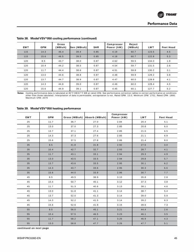
Performance Data
115 14.3 46.4 39.4 0.85 4.19 60.7 123.5 4.5
115 15.6 46.5 39.5 0.85 4.18 60.7 122.8 5.3
120 8.5 43.7 38.0 0.87 4.62 59.5 134.0 1.9
120 10.4 44.2 38.5 0.87 4.54 59.7 131.5 2.6
120 11.7 44.4 38.6 0.87 4.51 59.8 130.2 3.1
120 13.0 44.6 38.8 0.87 4.48 59.9 129.2 3.8
120 13.7 44.7 38.9 0.87 4.47 60.0 128.8 4.1
120 14.3 44.8 39.0 0.87 4.46 60.0 128.4 4.5
120 15.6 44.9 39.1 0.87 4.45 60.1 127.7 5.2
Notes: Cooling performance data is tabulated at 80°F DB/67°F WB at rated CFM. See performance correction tables to correct performance at conditions other than those tabulated. Interpolation of data is permissible; extrapolation is not. Rated GPM: 13.0; Minimum CFM: 1701; Rated CFM: 1890; Maximum CFM: 2079
Table 38. Model VSV*050 cooling performance (continued)
EWT GPMGross
(MBtuh) Sen (MBtuh) SHRCompressor Power (kW)
Reject (MBtuh) LWT Feet Head
Table 39. Model VSV*050 heating performance
EWT GPM Gross (MBtuh) Absorb (MBtuh)Compressor Power (kW) LWT Feet Head
25 11.7 36.7 27.0 2.84 20.4 5.1
25 13.0 37.0 27.3 2.85 20.8 6.0
25 13.7 37.1 27.4 2.85 21.0 6.5
25 14.3 37.3 27.6 2.85 21.1 6.9
25 15.6 37.5 27.8 2.86 21.4 8.0
35 8.5 41.8 31.8 2.92 27.5 3.0
35 10.4 42.7 32.7 2.93 28.7 4.1
35 11.7 43.1 33.1 2.94 29.3 4.9
35 13.0 43.5 33.5 2.94 29.8 5.7
35 13.7 43.6 33.5 2.95 30.1 6.2
35 14.3 43.7 33.6 2.95 30.3 6.6
35 15.6 44.0 33.9 2.96 30.7 7.7
45 8.5 49.5 38.9 3.10 35.8 2.8
45 10.4 50.7 40.1 3.12 37.3 3.8
45 11.7 51.3 40.6 3.13 38.1 4.6
45 13.0 51.8 41.1 3.14 38.7 5.4
45 13.7 52.0 41.3 3.14 39.0 5.9
45 14.3 52.2 41.5 3.14 39.2 6.3
45 15.6 52.6 41.9 3.15 39.6 7.3
55 8.5 56.0 45.1 3.21 44.4 2.6
55 10.4 57.5 46.5 3.23 46.1 3.5
55 11.7 58.2 47.1 3.25 46.9 4.3
55 13.0 58.8 47.7 3.26 47.7 5.1
continued on next page
WSHP-PRC026D-EN 45
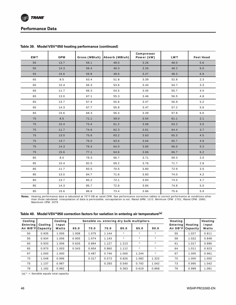
Performance Data
55 13.7 59.1 48.0 3.26 48.0 5.6
55 14.3 59.4 48.3 3.26 48.2 6.0
55 15.6 59.8 48.6 3.27 48.3 6.9
65 8.5 63.4 51.8 3.39 52.8 2.3
65 10.4 65.3 53.6 3.43 54.7 3.3
65 11.7 66.3 54.5 3.45 55.7 4.0
65 13.0 67.1 55.3 3.46 56.5 4.8
65 13.7 67.4 55.6 3.47 56.9 5.2
65 14.3 67.7 55.8 3.47 57.2 5.6
65 15.6 68.3 56.4 3.49 57.8 6.6
75 8.5 71.1 59.0 3.54 61.1 2.1
75 10.4 73.4 61.2 3.58 63.2 3.0
75 11.7 74.6 62.3 3.61 64.4 3.7
75 13.0 75.6 63.2 3.63 65.3 4.5
75 13.7 76.0 63.6 3.64 65.7 4.9
75 14.3 76.4 64.0 3.65 66.0 5.3
75 15.6 77.1 64.6 3.66 66.7 6.2
85 8.5 79.3 66.7 3.71 69.3 2.0
85 10.4 82.0 69.2 3.76 71.7 2.8
85 11.7 83.5 70.5 3.80 72.9 3.5
85 13.0 84.7 71.6 3.83 74.0 4.2
85 13.7 85.2 72.1 3.83 74.5 4.7
85 14.3 85.7 72.6 3.84 74.8 5.0
85 15.6 86.6 73.4 3.86 75.6 5.9
Notes: Heating performance data is tabulated at 70°F DB at rated CFM. See performance correction tables to correct performance at conditions other than those tabulated. Interpolation of data is permissible; extrapolation is not. Rated GPM: 13.0; Minimum CFM: 1701; Rated CFM: 1890; Maximum CFM: 2079
Table 39. Model VSV*050 heating performance (continued)
EWT GPM Gross (MBtuh) Absorb (MBtuh)Compressor Power (kW) LWT Feet Head
Table 40. Model VSV*050 correction factors for variation in entering air temperature(a)
Cooling Entering Air WB°F
Cooling Capacity
Cooling Input Watts
Sensible vs. entering dry bulb multipliers Heating Entering Air DB°F
Heating Capacity
Heating Input Watts65.0 70.0 75.0 80.0 85.0 90.0
50 0.935 1.005 1.008 1.075 1.144 * * * 55 1.027 0.811
55 0.934 1.006 0.905 1.074 1.143 * * * 58 1.022 0.848
60 0.933 1.006 0.626 0.884 1.127 1.213 * * 61 1.017 0.886
65 0.970 1.003 0.343 0.604 0.860 1.112 * * 64 1.011 0.923
67 1.000 1.000 0.487 0.746 1.000 1.244 * 67 1.005 0.961
70 1.048 0.996 0.317 0.573 0.826 1.082 1.322 70 1.000 1.000
75 1.137 0.987 0.283 0.540 0.792 1.042 73 0.995 1.042
78 1.192 0.982 0.363 0.619 0.868 76 0.989 1.081
(a) * = Sensible equals total capacity
46 WSHP-PRC026D-EN
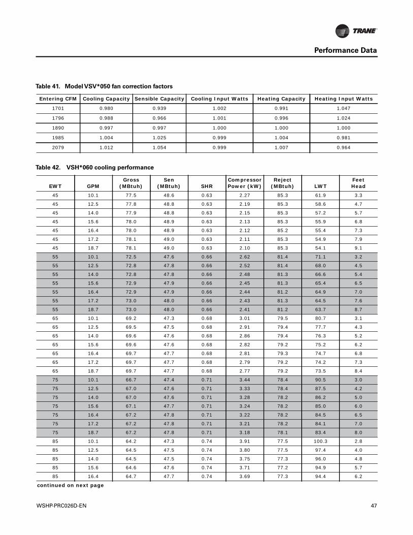
Performance Data
Table 41. Model VSV*050 fan correction factors
Entering CFM Cooling Capacity Sensible Capacity Cooling Input Watts Heating Capacity Heating Input Watts
1701 0.980 0.939 1.002 0.991 1.047
1796 0.988 0.966 1.001 0.996 1.024
1890 0.997 0.997 1.000 1.000 1.000
1985 1.004 1.025 0.999 1.004 0.981
2079 1.012 1.054 0.999 1.007 0.964
Table 42. VSH*060 cooling performance
EWT GPMGross
(MBtuh)Sen
(MBtuh) SHRCompressor Power (kW)
Reject (MBtuh) LWT
FeetHead
45 10.1 77.5 48.6 0.63 2.27 85.3 61.9 3.3
45 12.5 77.8 48.8 0.63 2.19 85.3 58.6 4.7
45 14.0 77.9 48.8 0.63 2.15 85.3 57.2 5.7
45 15.6 78.0 48.9 0.63 2.13 85.3 55.9 6.8
45 16.4 78.0 48.9 0.63 2.12 85.2 55.4 7.3
45 17.2 78.1 49.0 0.63 2.11 85.3 54.9 7.9
45 18.7 78.1 49.0 0.63 2.10 85.3 54.1 9.1
55 10.1 72.5 47.6 0.66 2.62 81.4 71.1 3.2
55 12.5 72.8 47.8 0.66 2.52 81.4 68.0 4.5
55 14.0 72.8 47.8 0.66 2.48 81.3 66.6 5.4
55 15.6 72.9 47.9 0.66 2.45 81.3 65.4 6.5
55 16.4 72.9 47.9 0.66 2.44 81.2 64.9 7.0
55 17.2 73.0 48.0 0.66 2.43 81.3 64.5 7.6
55 18.7 73.0 48.0 0.66 2.41 81.2 63.7 8.7
65 10.1 69.2 47.3 0.68 3.01 79.5 80.7 3.1
65 12.5 69.5 47.5 0.68 2.91 79.4 77.7 4.3
65 14.0 69.6 47.6 0.68 2.86 79.4 76.3 5.2
65 15.6 69.6 47.6 0.68 2.82 79.2 75.2 6.2
65 16.4 69.7 47.7 0.68 2.81 79.3 74.7 6.8
65 17.2 69.7 47.7 0.68 2.79 79.2 74.2 7.3
65 18.7 69.7 47.7 0.68 2.77 79.2 73.5 8.4
75 10.1 66.7 47.4 0.71 3.44 78.4 90.5 3.0
75 12.5 67.0 47.6 0.71 3.33 78.4 87.5 4.2
75 14.0 67.0 47.6 0.71 3.28 78.2 86.2 5.0
75 15.6 67.1 47.7 0.71 3.24 78.2 85.0 6.0
75 16.4 67.2 47.8 0.71 3.22 78.2 84.5 6.5
75 17.2 67.2 47.8 0.71 3.21 78.2 84.1 7.0
75 18.7 67.2 47.8 0.71 3.18 78.1 83.4 8.0
85 10.1 64.2 47.3 0.74 3.91 77.5 100.3 2.8
85 12.5 64.5 47.5 0.74 3.80 77.5 97.4 4.0
85 14.0 64.5 47.5 0.74 3.75 77.3 96.0 4.8
85 15.6 64.6 47.6 0.74 3.71 77.2 94.9 5.7
85 16.4 64.7 47.7 0.74 3.69 77.3 94.4 6.2
continued on next page
WSHP-PRC026D-EN 47
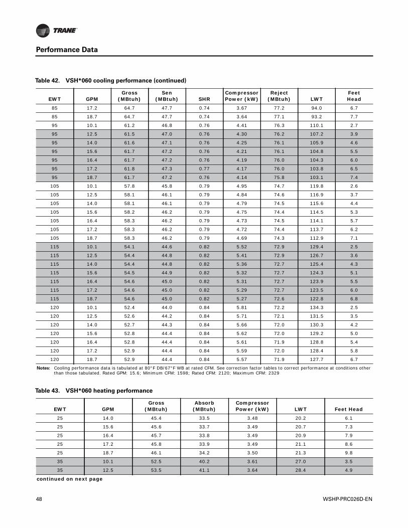
Performance Data
85 17.2 64.7 47.7 0.74 3.67 77.2 94.0 6.7
85 18.7 64.7 47.7 0.74 3.64 77.1 93.2 7.7
95 10.1 61.2 46.8 0.76 4.41 76.3 110.1 2.7
95 12.5 61.5 47.0 0.76 4.30 76.2 107.2 3.9
95 14.0 61.6 47.1 0.76 4.25 76.1 105.9 4.6
95 15.6 61.7 47.2 0.76 4.21 76.1 104.8 5.5
95 16.4 61.7 47.2 0.76 4.19 76.0 104.3 6.0
95 17.2 61.8 47.3 0.77 4.17 76.0 103.8 6.5
95 18.7 61.7 47.2 0.76 4.14 75.8 103.1 7.4
105 10.1 57.8 45.8 0.79 4.95 74.7 119.8 2.6
105 12.5 58.1 46.1 0.79 4.84 74.6 116.9 3.7
105 14.0 58.1 46.1 0.79 4.79 74.5 115.6 4.4
105 15.6 58.2 46.2 0.79 4.75 74.4 114.5 5.3
105 16.4 58.3 46.2 0.79 4.73 74.5 114.1 5.7
105 17.2 58.3 46.2 0.79 4.72 74.4 113.7 6.2
105 18.7 58.3 46.2 0.79 4.69 74.3 112.9 7.1
115 10.1 54.1 44.6 0.82 5.52 72.9 129.4 2.5
115 12.5 54.4 44.8 0.82 5.41 72.9 126.7 3.6
115 14.0 54.4 44.8 0.82 5.36 72.7 125.4 4.3
115 15.6 54.5 44.9 0.82 5.32 72.7 124.3 5.1
115 16.4 54.6 45.0 0.82 5.31 72.7 123.9 5.5
115 17.2 54.6 45.0 0.82 5.29 72.7 123.5 6.0
115 18.7 54.6 45.0 0.82 5.27 72.6 122.8 6.8
120 10.1 52.4 44.0 0.84 5.81 72.2 134.3 2.5
120 12.5 52.6 44.2 0.84 5.71 72.1 131.5 3.5
120 14.0 52.7 44.3 0.84 5.66 72.0 130.3 4.2
120 15.6 52.8 44.4 0.84 5.62 72.0 129.2 5.0
120 16.4 52.8 44.4 0.84 5.61 71.9 128.8 5.4
120 17.2 52.9 44.4 0.84 5.59 72.0 128.4 5.8
120 18.7 52.9 44.4 0.84 5.57 71.9 127.7 6.7
Notes: Cooling performance data is tabulated at 80°F DB/67°F WB at rated CFM. See correction factor tables to correct performance at conditions other than those tabulated. Rated GPM: 15.6; Minimum CFM: 1598; Rated CFM: 2120; Maximum CFM: 2329
Table 42. VSH*060 cooling performance (continued)
EWT GPMGross
(MBtuh)Sen
(MBtuh) SHRCompressor Power (kW)
Reject (MBtuh) LWT
FeetHead
Table 43. VSH*060 heating performance
EWT GPMGross
(MBtuh)Absorb
(MBtuh)Compressor Power (kW) LWT Feet Head
25 14.0 45.4 33.5 3.48 20.2 6.1
25 15.6 45.6 33.7 3.49 20.7 7.3
25 16.4 45.7 33.8 3.49 20.9 7.9
25 17.2 45.8 33.9 3.49 21.1 8.6
25 18.7 46.1 34.2 3.50 21.3 9.8
35 10.1 52.5 40.2 3.61 27.0 3.5
35 12.5 53.5 41.1 3.64 28.4 4.9
continued on next page
48 WSHP-PRC026D-EN
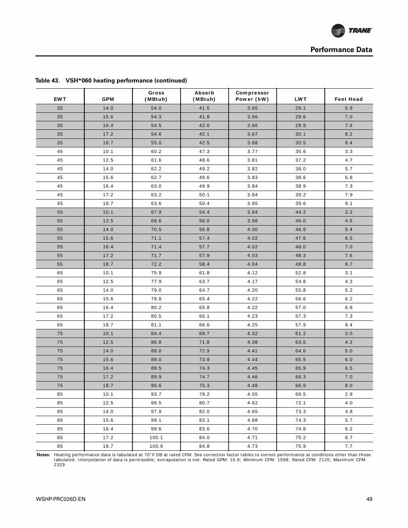
Performance Data
35 14.0 54.0 41.5 3.65 29.1 5.9
35 15.6 54.3 41.8 3.66 29.6 7.0
35 16.4 54.5 42.0 3.66 29.9 7.6
35 17.2 54.6 42.1 3.67 30.1 8.2
35 18.7 55.0 42.5 3.68 30.5 9.4
45 10.1 60.2 47.3 3.77 35.6 3.3
45 12.5 61.6 48.6 3.81 37.2 4.7
45 14.0 62.2 49.2 3.82 38.0 5.7
45 15.6 62.7 49.6 3.83 38.6 6.8
45 16.4 63.0 49.9 3.84 38.9 7.3
45 17.2 63.2 50.1 3.84 39.2 7.9
45 18.7 63.6 50.4 3.85 39.6 9.1
55 10.1 67.9 54.4 3.94 44.2 3.2
55 12.5 69.6 56.0 3.98 46.0 4.5
55 14.0 70.5 56.8 4.00 46.9 5.4
55 15.6 71.1 57.4 4.02 47.6 6.5
55 16.4 71.4 57.7 4.02 48.0 7.0
55 17.2 71.7 57.9 4.03 48.3 7.6
55 18.7 72.2 58.4 4.04 48.8 8.7
65 10.1 75.9 61.8 4.12 52.8 3.1
65 12.5 77.9 63.7 4.17 54.8 4.3
65 14.0 79.0 64.7 4.20 55.8 5.2
65 15.6 79.8 65.4 4.22 56.6 6.2
65 16.4 80.2 65.8 4.22 57.0 6.8
65 17.2 80.5 66.1 4.23 57.3 7.3
65 18.7 81.1 66.6 4.25 57.9 8.4
75 10.1 84.4 69.7 4.32 61.2 3.0
75 12.5 86.8 71.8 4.38 63.5 4.2
75 14.0 88.0 72.9 4.41 64.6 5.0
75 15.6 89.0 73.9 4.44 65.5 6.0
75 16.4 89.5 74.3 4.45 65.9 6.5
75 17.2 89.9 74.7 4.46 66.3 7.0
75 18.7 90.6 75.3 4.48 66.9 8.0
85 10.1 93.7 78.2 4.55 69.5 2.8
85 12.5 96.5 80.7 4.62 72.1 4.0
85 14.0 97.9 82.0 4.65 73.3 4.8
85 15.6 99.1 83.1 4.68 74.3 5.7
85 16.4 99.6 83.6 4.70 74.8 6.2
85 17.2 100.1 84.0 4.71 75.2 6.7
85 18.7 100.9 84.8 4.73 75.9 7.7
Notes: Heating performance data is tabulated at 70°F DB at rated CFM. See correction factor tables to correct performance at conditions other than those tabulated. Interpolation of data is permissible; extrapolation is not. Rated GPM: 15.6; Minimum CFM: 1598; Rated CFM: 2120; Maximum CFM: 2329
Table 43. VSH*060 heating performance (continued)
EWT GPMGross
(MBtuh)Absorb
(MBtuh)Compressor Power (kW) LWT Feet Head
WSHP-PRC026D-EN 49
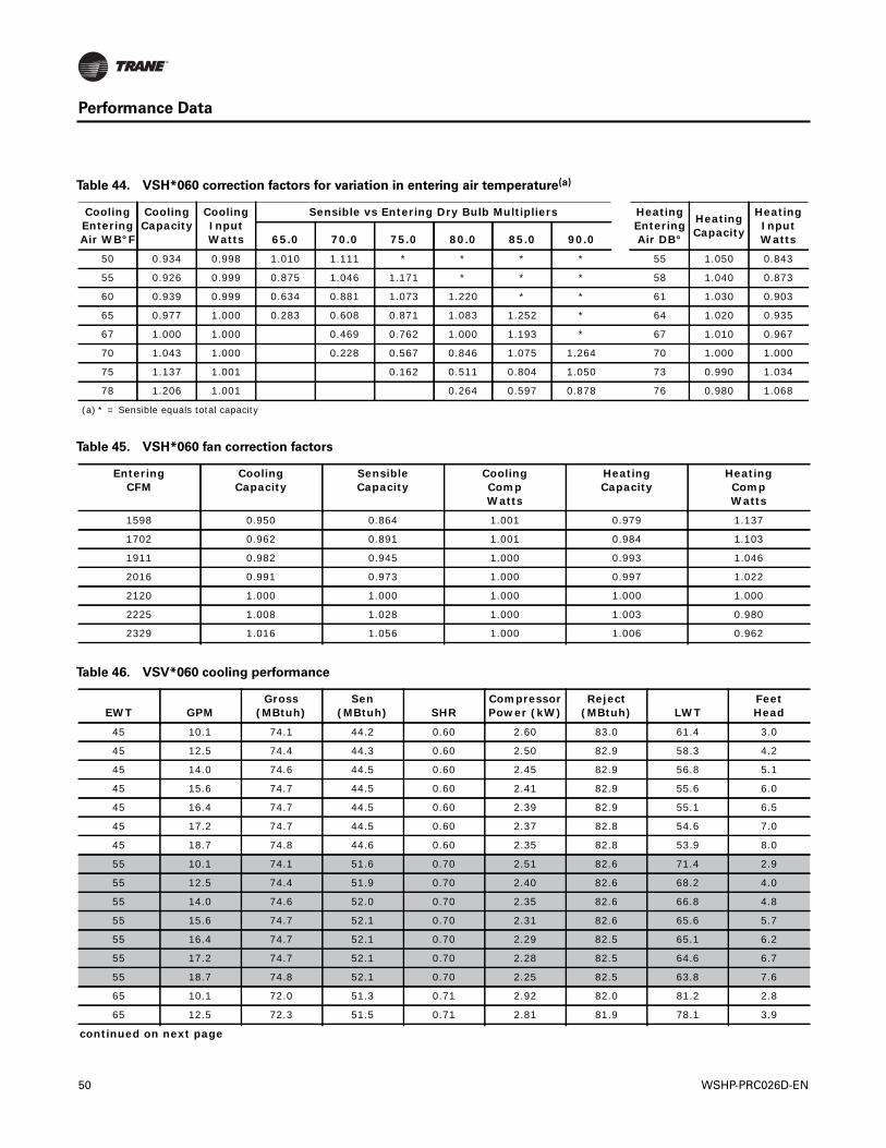
Performance Data
Table 44. VSH*060 correction factors for variation in entering air temperature(a)
Cooling Entering Air WB°F
Cooling Capacity
Cooling Input Watts
Sensible vs Entering Dry Bulb Multipliers Heating Entering Air DB°
Heating Capacity
Heating Input Watts65.0 70.0 75.0 80.0 85.0 90.0
50 0.934 0.998 1.010 1.111 * * * * 55 1.050 0.843
55 0.926 0.999 0.875 1.046 1.171 * * * 58 1.040 0.873
60 0.939 0.999 0.634 0.881 1.073 1.220 * * 61 1.030 0.903
65 0.977 1.000 0.283 0.608 0.871 1.083 1.252 * 64 1.020 0.935
67 1.000 1.000 0.469 0.762 1.000 1.193 * 67 1.010 0.967
70 1.043 1.000 0.228 0.567 0.846 1.075 1.264 70 1.000 1.000
75 1.137 1.001 0.162 0.511 0.804 1.050 73 0.990 1.034
78 1.206 1.001 0.264 0.597 0.878 76 0.980 1.068
(a) * = Sensible equals total capacity
Table 45. VSH*060 fan correction factors
Entering CFM
CoolingCapacity
SensibleCapacity
Cooling CompWatts
HeatingCapacity
Heating CompWatts
1598 0.950 0.864 1.001 0.979 1.137
1702 0.962 0.891 1.001 0.984 1.103
1911 0.982 0.945 1.000 0.993 1.046
2016 0.991 0.973 1.000 0.997 1.022
2120 1.000 1.000 1.000 1.000 1.000
2225 1.008 1.028 1.000 1.003 0.980
2329 1.016 1.056 1.000 1.006 0.962
Table 46. VSV*060 cooling performance
EWT GPMGross
(MBtuh)Sen
(MBtuh) SHRCompressor Power (kW)
Reject (MBtuh) LWT
FeetHead
45 10.1 74.1 44.2 0.60 2.60 83.0 61.4 3.0
45 12.5 74.4 44.3 0.60 2.50 82.9 58.3 4.2
45 14.0 74.6 44.5 0.60 2.45 82.9 56.8 5.1
45 15.6 74.7 44.5 0.60 2.41 82.9 55.6 6.0
45 16.4 74.7 44.5 0.60 2.39 82.9 55.1 6.5
45 17.2 74.7 44.5 0.60 2.37 82.8 54.6 7.0
45 18.7 74.8 44.6 0.60 2.35 82.8 53.9 8.0
55 10.1 74.1 51.6 0.70 2.51 82.6 71.4 2.9
55 12.5 74.4 51.9 0.70 2.40 82.6 68.2 4.0
55 14.0 74.6 52.0 0.70 2.35 82.6 66.8 4.8
55 15.6 74.7 52.1 0.70 2.31 82.6 65.6 5.7
55 16.4 74.7 52.1 0.70 2.29 82.5 65.1 6.2
55 17.2 74.7 52.1 0.70 2.28 82.5 64.6 6.7
55 18.7 74.8 52.1 0.70 2.25 82.5 63.8 7.6
65 10.1 72.0 51.3 0.71 2.92 82.0 81.2 2.8
65 12.5 72.3 51.5 0.71 2.81 81.9 78.1 3.9
continued on next page
50 WSHP-PRC026D-EN
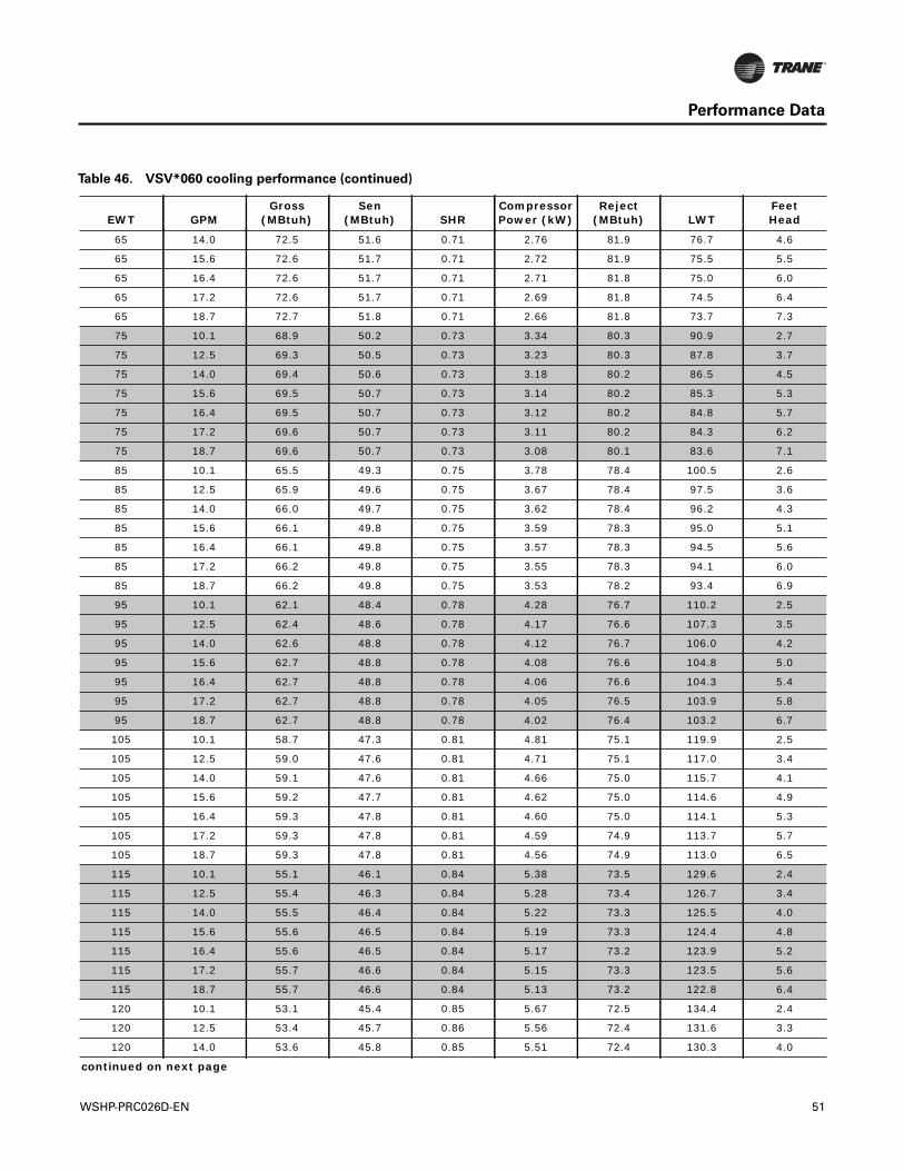
Performance Data
65 14.0 72.5 51.6 0.71 2.76 81.9 76.7 4.6
65 15.6 72.6 51.7 0.71 2.72 81.9 75.5 5.5
65 16.4 72.6 51.7 0.71 2.71 81.8 75.0 6.0
65 17.2 72.6 51.7 0.71 2.69 81.8 74.5 6.4
65 18.7 72.7 51.8 0.71 2.66 81.8 73.7 7.3
75 10.1 68.9 50.2 0.73 3.34 80.3 90.9 2.7
75 12.5 69.3 50.5 0.73 3.23 80.3 87.8 3.7
75 14.0 69.4 50.6 0.73 3.18 80.2 86.5 4.5
75 15.6 69.5 50.7 0.73 3.14 80.2 85.3 5.3
75 16.4 69.5 50.7 0.73 3.12 80.2 84.8 5.7
75 17.2 69.6 50.7 0.73 3.11 80.2 84.3 6.2
75 18.7 69.6 50.7 0.73 3.08 80.1 83.6 7.1
85 10.1 65.5 49.3 0.75 3.78 78.4 100.5 2.6
85 12.5 65.9 49.6 0.75 3.67 78.4 97.5 3.6
85 14.0 66.0 49.7 0.75 3.62 78.4 96.2 4.3
85 15.6 66.1 49.8 0.75 3.59 78.3 95.0 5.1
85 16.4 66.1 49.8 0.75 3.57 78.3 94.5 5.6
85 17.2 66.2 49.8 0.75 3.55 78.3 94.1 6.0
85 18.7 66.2 49.8 0.75 3.53 78.2 93.4 6.9
95 10.1 62.1 48.4 0.78 4.28 76.7 110.2 2.5
95 12.5 62.4 48.6 0.78 4.17 76.6 107.3 3.5
95 14.0 62.6 48.8 0.78 4.12 76.7 106.0 4.2
95 15.6 62.7 48.8 0.78 4.08 76.6 104.8 5.0
95 16.4 62.7 48.8 0.78 4.06 76.6 104.3 5.4
95 17.2 62.7 48.8 0.78 4.05 76.5 103.9 5.8
95 18.7 62.7 48.8 0.78 4.02 76.4 103.2 6.7
105 10.1 58.7 47.3 0.81 4.81 75.1 119.9 2.5
105 12.5 59.0 47.6 0.81 4.71 75.1 117.0 3.4
105 14.0 59.1 47.6 0.81 4.66 75.0 115.7 4.1
105 15.6 59.2 47.7 0.81 4.62 75.0 114.6 4.9
105 16.4 59.3 47.8 0.81 4.60 75.0 114.1 5.3
105 17.2 59.3 47.8 0.81 4.59 74.9 113.7 5.7
105 18.7 59.3 47.8 0.81 4.56 74.9 113.0 6.5
115 10.1 55.1 46.1 0.84 5.38 73.5 129.6 2.4
115 12.5 55.4 46.3 0.84 5.28 73.4 126.7 3.4
115 14.0 55.5 46.4 0.84 5.22 73.3 125.5 4.0
115 15.6 55.6 46.5 0.84 5.19 73.3 124.4 4.8
115 16.4 55.6 46.5 0.84 5.17 73.2 123.9 5.2
115 17.2 55.7 46.6 0.84 5.15 73.3 123.5 5.6
115 18.7 55.7 46.6 0.84 5.13 73.2 122.8 6.4
120 10.1 53.1 45.4 0.85 5.67 72.5 134.4 2.4
120 12.5 53.4 45.7 0.86 5.56 72.4 131.6 3.3
120 14.0 53.6 45.8 0.85 5.51 72.4 130.3 4.0
continued on next page
Table 46. VSV*060 cooling performance (continued)
EWT GPMGross
(MBtuh)Sen
(MBtuh) SHRCompressor Power (kW)
Reject (MBtuh) LWT
FeetHead
WSHP-PRC026D-EN 51
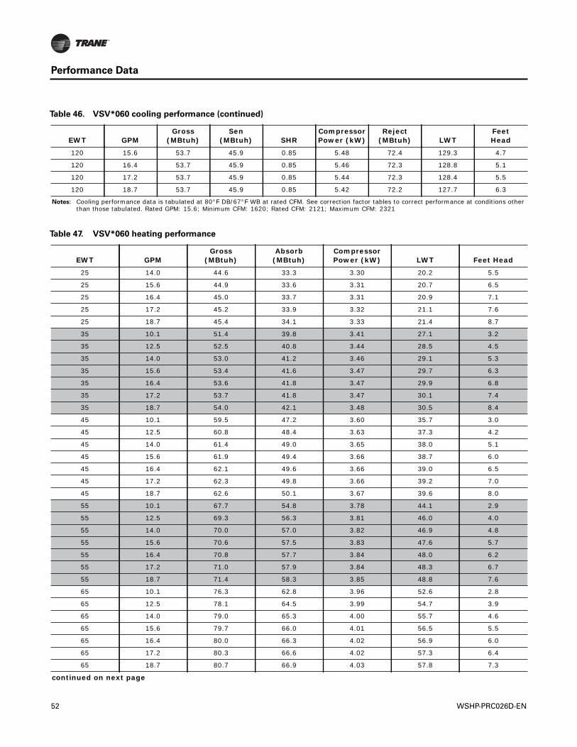
Performance Data
120 15.6 53.7 45.9 0.85 5.48 72.4 129.3 4.7
120 16.4 53.7 45.9 0.85 5.46 72.3 128.8 5.1
120 17.2 53.7 45.9 0.85 5.44 72.3 128.4 5.5
120 18.7 53.7 45.9 0.85 5.42 72.2 127.7 6.3
Notes: Cooling performance data is tabulated at 80°F DB/67°F WB at rated CFM. See correction factor tables to correct performance at conditions other than those tabulated. Rated GPM: 15.6; Minimum CFM: 1620; Rated CFM: 2121; Maximum CFM: 2321
Table 46. VSV*060 cooling performance (continued)
EWT GPMGross
(MBtuh)Sen
(MBtuh) SHRCompressor Power (kW)
Reject (MBtuh) LWT
FeetHead
Table 47. VSV*060 heating performance
EWT GPMGross
(MBtuh)Absorb
(MBtuh)Compressor Power (kW) LWT Feet Head
25 14.0 44.6 33.3 3.30 20.2 5.5
25 15.6 44.9 33.6 3.31 20.7 6.5
25 16.4 45.0 33.7 3.31 20.9 7.1
25 17.2 45.2 33.9 3.32 21.1 7.6
25 18.7 45.4 34.1 3.33 21.4 8.7
35 10.1 51.4 39.8 3.41 27.1 3.2
35 12.5 52.5 40.8 3.44 28.5 4.5
35 14.0 53.0 41.2 3.46 29.1 5.3
35 15.6 53.4 41.6 3.47 29.7 6.3
35 16.4 53.6 41.8 3.47 29.9 6.8
35 17.2 53.7 41.8 3.47 30.1 7.4
35 18.7 54.0 42.1 3.48 30.5 8.4
45 10.1 59.5 47.2 3.60 35.7 3.0
45 12.5 60.8 48.4 3.63 37.3 4.2
45 14.0 61.4 49.0 3.65 38.0 5.1
45 15.6 61.9 49.4 3.66 38.7 6.0
45 16.4 62.1 49.6 3.66 39.0 6.5
45 17.2 62.3 49.8 3.66 39.2 7.0
45 18.7 62.6 50.1 3.67 39.6 8.0
55 10.1 67.7 54.8 3.78 44.1 2.9
55 12.5 69.3 56.3 3.81 46.0 4.0
55 14.0 70.0 57.0 3.82 46.9 4.8
55 15.6 70.6 57.5 3.83 47.6 5.7
55 16.4 70.8 57.7 3.84 48.0 6.2
55 17.2 71.0 57.9 3.84 48.3 6.7
55 18.7 71.4 58.3 3.85 48.8 7.6
65 10.1 76.3 62.8 3.96 52.6 2.8
65 12.5 78.1 64.5 3.99 54.7 3.9
65 14.0 79.0 65.3 4.00 55.7 4.6
65 15.6 79.7 66.0 4.01 56.5 5.5
65 16.4 80.0 66.3 4.02 56.9 6.0
65 17.2 80.3 66.6 4.02 57.3 6.4
65 18.7 80.7 66.9 4.03 57.8 7.3
continued on next page
52 WSHP-PRC026D-EN
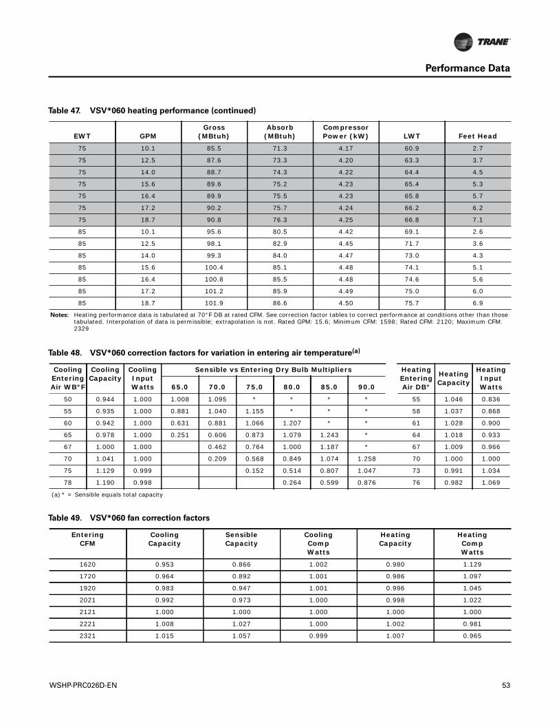
Performance Data
75 10.1 85.5 71.3 4.17 60.9 2.7
75 12.5 87.6 73.3 4.20 63.3 3.7
75 14.0 88.7 74.3 4.22 64.4 4.5
75 15.6 89.6 75.2 4.23 65.4 5.3
75 16.4 89.9 75.5 4.23 65.8 5.7
75 17.2 90.2 75.7 4.24 66.2 6.2
75 18.7 90.8 76.3 4.25 66.8 7.1
85 10.1 95.6 80.5 4.42 69.1 2.6
85 12.5 98.1 82.9 4.45 71.7 3.6
85 14.0 99.3 84.0 4.47 73.0 4.3
85 15.6 100.4 85.1 4.48 74.1 5.1
85 16.4 100.8 85.5 4.48 74.6 5.6
85 17.2 101.2 85.9 4.49 75.0 6.0
85 18.7 101.9 86.6 4.50 75.7 6.9
Notes: Heating performance data is tabulated at 70°F DB at rated CFM. See correction factor tables to correct performance at conditions other than those tabulated. Interpolation of data is permissible; extrapolation is not. Rated GPM: 15.6; Minimum CFM: 1598; Rated CFM: 2120; Maximum CFM: 2329
Table 47. VSV*060 heating performance (continued)
EWT GPMGross
(MBtuh)Absorb
(MBtuh)Compressor Power (kW) LWT Feet Head
Table 48. VSV*060 correction factors for variation in entering air temperature(a)
Cooling Entering Air WB°F
Cooling Capacity
Cooling Input Watts
Sensible vs Entering Dry Bulb Multipliers Heating Entering Air DB°
Heating Capacity
Heating Input Watts65.0 70.0 75.0 80.0 85.0 90.0
50 0.944 1.000 1.008 1.095 * * * * 55 1.046 0.836
55 0.935 1.000 0.881 1.040 1.155 * * * 58 1.037 0.868
60 0.942 1.000 0.631 0.881 1.066 1.207 * * 61 1.028 0.900
65 0.978 1.000 0.251 0.606 0.873 1.079 1.243 * 64 1.018 0.933
67 1.000 1.000 0.462 0.764 1.000 1.187 * 67 1.009 0.966
70 1.041 1.000 0.209 0.568 0.849 1.074 1.258 70 1.000 1.000
75 1.129 0.999 0.152 0.514 0.807 1.047 73 0.991 1.034
78 1.190 0.998 0.264 0.599 0.876 76 0.982 1.069
(a) * = Sensible equals total capacity
Table 49. VSV*060 fan correction factors
Entering CFM
CoolingCapacity
SensibleCapacity
Cooling CompWatts
HeatingCapacity
Heating CompWatts
1620 0.953 0.866 1.002 0.980 1.129
1720 0.964 0.892 1.001 0.986 1.097
1920 0.983 0.947 1.001 0.996 1.045
2021 0.992 0.973 1.000 0.998 1.022
2121 1.000 1.000 1.000 1.000 1.000
2221 1.008 1.027 1.000 1.002 0.981
2321 1.015 1.057 0.999 1.007 0.965
WSHP-PRC026D-EN 53
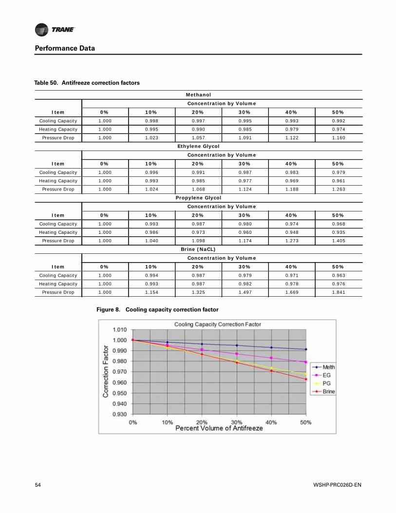
Performance Data
Table 50. Antifreeze correction factors
Methanol
Item
Concentration by Volume
0% 10% 20% 30% 40% 50%
Cooling Capacity 1.000 0.998 0.997 0.995 0.993 0.992
Heating Capacity 1.000 0.995 0.990 0.985 0.979 0.974
Pressure Drop 1.000 1.023 1.057 1.091 1.122 1.160
Ethylene Glycol
Item
Concentration by Volume
0% 10% 20% 30% 40% 50%
Cooling Capacity 1.000 0.996 0.991 0.987 0.983 0.979
Heating Capacity 1.000 0.993 0.985 0.977 0.969 0.961
Pressure Drop 1.000 1.024 1.068 1.124 1.188 1.263
Propylene Glycol
Item
Concentration by Volume
0% 10% 20% 30% 40% 50%
Cooling Capacity 1.000 0.993 0.987 0.980 0.974 0.968
Heating Capacity 1.000 0.986 0.973 0.960 0.948 0.935
Pressure Drop 1.000 1.040 1.098 1.174 1.273 1.405
Brine (NaCL)
Item
Concentration by Volume
0% 10% 20% 30% 40% 50%
Cooling Capacity 1.000 0.994 0.987 0.979 0.971 0.963
Heating Capacity 1.000 0.993 0.987 0.982 0.978 0.976
Pressure Drop 1.000 1.154 1.325 1.497 1.669 1.841
Figure 8. Cooling capacity correction factor
54 WSHP-PRC026D-EN
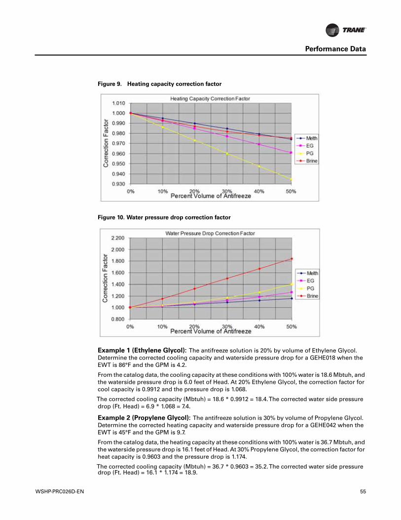
Performance Data
Example 1 (Ethylene Glycol): The antifreeze solution is 20% by volume of Ethylene Glycol.Determine the corrected cooling capacity and waterside pressure drop for a GEHE018 when theEWT is 86°F and the GPM is 4.2.
From the catalog data, the cooling capacity at these conditions with 100% water is 18.6 Mbtuh, andthe waterside pressure drop is 6.0 feet of Head. At 20% Ethylene Glycol, the correction factor forcool capacity is 0.9912 and the pressure drop is 1.068.
The corrected cooling capacity (Mbtuh) = 18.6 * 0.9912 = 18.4.The corrected water side pressuredrop (Ft. Head) = 6.9 * 1.068 = 7.4.
Example 2 (Propylene Glycol): The antifreeze solution is 30% by volume of Propylene Glycol.Determine the corrected heating capacity and waterside pressure drop for a GEHE042 when theEWT is 45°F and the GPM is 9.7.
From the catalog data, the heating capacity at these conditions with 100% water is 36.7 Mbtuh, andthe waterside pressure drop is 16.1 feet of Head. At 30% Propylene Glycol, the correction factor forheat capacity is 0.9603 and the pressure drop is 1.174.
The corrected cooling capacity (Mbtuh) = 36.7 * 0.9603 = 35.2.The corrected water side pressuredrop (Ft. Head) = 16.1 * 1.174 = 18.9.
Figure 9. Heating capacity correction factor
Figure 10. Water pressure drop correction factor
WSHP-PRC026D-EN 55
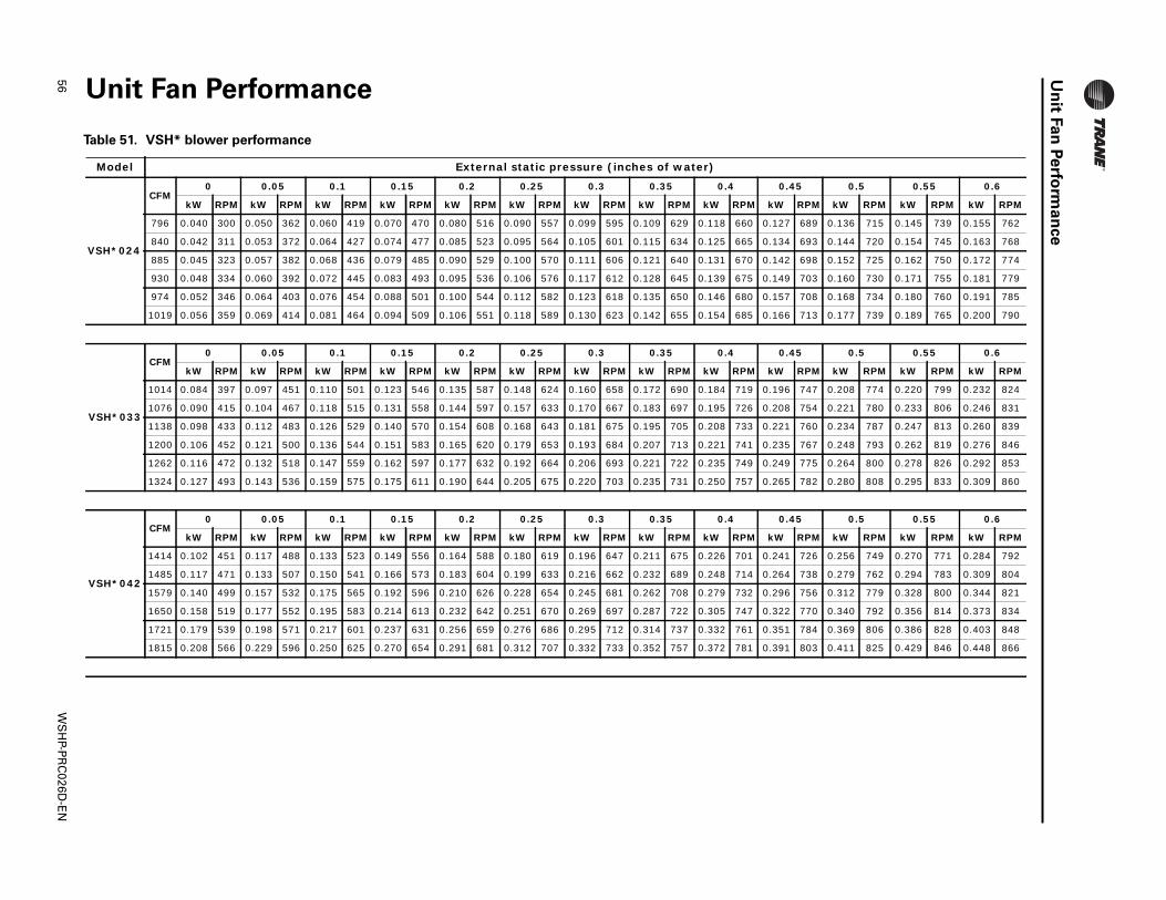
56W
SH
P-PR
C026D
-EN
Un
itFan
Perfo
rman
ce
Unit Fan Performance
Table 51. VSH* blower performance
0.5 0.55 0.6
W RPM kW RPM kW RPM
136 715 0.145 739 0.155 762
144 720 0.154 745 0.163 768
152 725 0.162 750 0.172 774
160 730 0.171 755 0.181 779
168 734 0.180 760 0.191 785
177 739 0.189 765 0.200 790
0.5 0.55 0.6
W RPM kW RPM kW RPM
208 774 0.220 799 0.232 824
221 780 0.233 806 0.246 831
234 787 0.247 813 0.260 839
248 793 0.262 819 0.276 846
264 800 0.278 826 0.292 853
280 808 0.295 833 0.309 860
0.5 0.55 0.6
W RPM kW RPM kW RPM
256 749 0.270 771 0.284 792
279 762 0.294 783 0.309 804
312 779 0.328 800 0.344 821
340 792 0.356 814 0.373 834
369 806 0.386 828 0.403 848
411 825 0.429 846 0.448 866
Model External static pressure (inches of water)
VSH*024
CFM0 0.05 0.1 0.15 0.2 0.25 0.3 0.35 0.4 0.45
kW RPM kW RPM kW RPM kW RPM kW RPM kW RPM kW RPM kW RPM kW RPM kW RPM k
796 0.040 300 0.050 362 0.060 419 0.070 470 0.080 516 0.090 557 0.099 595 0.109 629 0.118 660 0.127 689 0.
840 0.042 311 0.053 372 0.064 427 0.074 477 0.085 523 0.095 564 0.105 601 0.115 634 0.125 665 0.134 693 0.
885 0.045 323 0.057 382 0.068 436 0.079 485 0.090 529 0.100 570 0.111 606 0.121 640 0.131 670 0.142 698 0.
930 0.048 334 0.060 392 0.072 445 0.083 493 0.095 536 0.106 576 0.117 612 0.128 645 0.139 675 0.149 703 0.
974 0.052 346 0.064 403 0.076 454 0.088 501 0.100 544 0.112 582 0.123 618 0.135 650 0.146 680 0.157 708 0.
1019 0.056 359 0.069 414 0.081 464 0.094 509 0.106 551 0.118 589 0.130 623 0.142 655 0.154 685 0.166 713 0.
VSH*033
CFM0 0.05 0.1 0.15 0.2 0.25 0.3 0.35 0.4 0.45
kW RPM kW RPM kW RPM kW RPM kW RPM kW RPM kW RPM kW RPM kW RPM kW RPM k
1014 0.084 397 0.097 451 0.110 501 0.123 546 0.135 587 0.148 624 0.160 658 0.172 690 0.184 719 0.196 747 0.
1076 0.090 415 0.104 467 0.118 515 0.131 558 0.144 597 0.157 633 0.170 667 0.183 697 0.195 726 0.208 754 0.
1138 0.098 433 0.112 483 0.126 529 0.140 570 0.154 608 0.168 643 0.181 675 0.195 705 0.208 733 0.221 760 0.
1200 0.106 452 0.121 500 0.136 544 0.151 583 0.165 620 0.179 653 0.193 684 0.207 713 0.221 741 0.235 767 0.
1262 0.116 472 0.132 518 0.147 559 0.162 597 0.177 632 0.192 664 0.206 693 0.221 722 0.235 749 0.249 775 0.
1324 0.127 493 0.143 536 0.159 575 0.175 611 0.190 644 0.205 675 0.220 703 0.235 731 0.250 757 0.265 782 0.
VSH*042
CFM0 0.05 0.1 0.15 0.2 0.25 0.3 0.35 0.4 0.45
kW RPM kW RPM kW RPM kW RPM kW RPM kW RPM kW RPM kW RPM kW RPM kW RPM k
1414 0.102 451 0.117 488 0.133 523 0.149 556 0.164 588 0.180 619 0.196 647 0.211 675 0.226 701 0.241 726 0.
1485 0.117 471 0.133 507 0.150 541 0.166 573 0.183 604 0.199 633 0.216 662 0.232 689 0.248 714 0.264 738 0.
1579 0.140 499 0.157 532 0.175 565 0.192 596 0.210 626 0.228 654 0.245 681 0.262 708 0.279 732 0.296 756 0.
1650 0.158 519 0.177 552 0.195 583 0.214 613 0.232 642 0.251 670 0.269 697 0.287 722 0.305 747 0.322 770 0.
1721 0.179 539 0.198 571 0.217 601 0.237 631 0.256 659 0.276 686 0.295 712 0.314 737 0.332 761 0.351 784 0.
1815 0.208 566 0.229 596 0.250 625 0.270 654 0.291 681 0.312 707 0.332 733 0.352 757 0.372 781 0.391 803 0.
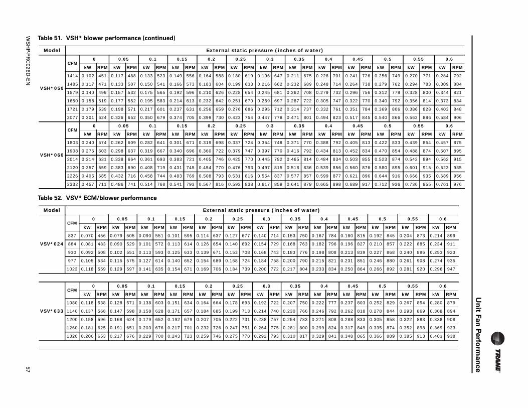
WS
HP-P
RC
026D-E
N57
Un
itFan
Perfo
rma
nce
CFM0 0.05 0.1 0.15 0.2 0.25 0.3 0.35 0.4 0.45 0.5 0.55 0.6
kW RPM kW RPM kW RPM kW RPM kW RPM kW RPM kW RPM kW RPM kW RPM kW RPM kW RPM kW RPM kW RPM
256 749 0.270 771 0.284 792
279 762 0.294 783 0.309 804
312 779 0.328 800 0.344 821
340 792 0.356 814 0.373 834
369 806 0.386 828 0.403 848
540 866 0.562 886 0.584 906
0.5 0.55 0.6
W RPM kW RPM kW RPM
422 833 0.439 854 0.457 875
470 854 0.488 874 0.507 895
523 874 0.542 894 0.562 915
580 895 0.601 915 0.623 935
644 916 0.666 935 0.689 956
712 936 0.736 955 0.761 976
Table 51. VSH* blower performance (continued)
Model External static pressure (inches of water)
0.5 0.55 0.6
RPM kW RPM kW RPM
2 845 0.204 873 0.214 899
0 857 0.222 885 0.234 911
7 868 0.240 896 0.253 923
6 880 0.261 908 0.274 935
6 892 0.281 920 0.296 947
0.5 0.55 0.6
RPM kW RPM kW RPM
2 829 0.267 854 0.280 879
8 844 0.293 869 0.308 894
5 858 0.322 883 0.338 908
5 874 0.352 898 0.369 923
6 889 0.385 913 0.403 938
VSH*050
1414 0.102 451 0.117 488 0.133 523 0.149 556 0.164 588 0.180 619 0.196 647 0.211 675 0.226 701 0.241 726 0.
1485 0.117 471 0.133 507 0.150 541 0.166 573 0.183 604 0.199 633 0.216 662 0.232 689 0.248 714 0.264 738 0.
1579 0.140 499 0.157 532 0.175 565 0.192 596 0.210 626 0.228 654 0.245 681 0.262 708 0.279 732 0.296 756 0.
1650 0.158 519 0.177 552 0.195 583 0.214 613 0.232 642 0.251 670 0.269 697 0.287 722 0.305 747 0.322 770 0.
1721 0.179 539 0.198 571 0.217 601 0.237 631 0.256 659 0.276 686 0.295 712 0.314 737 0.332 761 0.351 784 0.
2077 0.301 624 0.326 652 0.350 679 0.374 705 0.399 730 0.423 754 0.447 778 0.471 801 0.494 823 0.517 845 0.
VSH*060
CFM0 0.05 0.1 0.15 0.2 0.25 0.3 0.35 0.4 0.45
kW RPM kW RPM kW RPM kW RPM kW RPM kW RPM kW RPM kW RPM kW RPM kW RPM k
1803 0.240 574 0.262 609 0.282 641 0.301 671 0.319 698 0.337 724 0.354 748 0.371 770 0.388 792 0.405 813 0.
1908 0.275 603 0.298 637 0.319 667 0.340 696 0.360 722 0.379 747 0.397 770 0.416 792 0.434 813 0.452 834 0.
2014 0.314 631 0.338 664 0.361 693 0.383 721 0.405 746 0.425 770 0.445 792 0.465 814 0.484 834 0.503 855 0.
2120 0.357 659 0.383 690 0.408 719 0.431 745 0.454 770 0.476 793 0.497 815 0.518 836 0.539 856 0.560 876 0.
2226 0.405 685 0.432 716 0.458 744 0.483 769 0.508 793 0.531 816 0.554 837 0.577 857 0.599 877 0.621 896 0.
2332 0.457 711 0.486 741 0.514 768 0.541 793 0.567 816 0.592 838 0.617 859 0.641 879 0.665 898 0.689 917 0.
Table 52. VSV* ECM/blower performance
Model External static pressure (inches of water)
VSV*024
CFM0 0.05 0.1 0.15 0.2 0.25 0.3 0.35 0.4 0.45
kW RPM kW RPM kW RPM kW RPM kW RPM kW RPM kW RPM kW RPM kW RPM kW RPM kW
837 0.070 456 0.079 505 0.090 551 0.101 595 0.114 637 0.127 677 0.140 714 0.153 750 0.167 784 0.180 815 0.19
884 0.081 483 0.090 529 0.101 572 0.113 614 0.126 654 0.140 692 0.154 729 0.168 763 0.182 796 0.196 827 0.21
930 0.092 508 0.102 551 0.113 593 0.125 633 0.139 671 0.153 708 0.168 743 0.183 776 0.198 808 0.213 839 0.22
977 0.105 534 0.115 575 0.127 614 0.140 652 0.154 689 0.168 724 0.184 758 0.200 790 0.215 821 0.231 851 0.24
1023 0.118 559 0.129 597 0.141 635 0.154 671 0.169 706 0.184 739 0.200 772 0.217 804 0.233 834 0.250 864 0.26
VSV*033
CFM0 0.05 0.1 0.15 0.2 0.25 0.3 0.35 0.4 0.45
kW RPM kW RPM kW RPM kW RPM kW RPM kW RPM kW RPM kW RPM kW RPM kW RPM kW
1080 0.118 538 0.128 571 0.138 603 0.151 634 0.164 664 0.178 693 0.192 722 0.207 750 0.222 777 0.237 803 0.25
1140 0.137 568 0.147 598 0.158 628 0.171 657 0.184 685 0.199 713 0.214 740 0.230 766 0.246 792 0.262 818 0.27
1200 0.158 596 0.168 624 0.179 652 0.192 679 0.207 705 0.222 731 0.238 757 0.254 783 0.271 808 0.288 833 0.30
1260 0.181 625 0.191 651 0.203 676 0.217 701 0.232 726 0.247 751 0.264 775 0.281 800 0.299 824 0.317 849 0.33
1320 0.206 653 0.217 676 0.229 700 0.243 723 0.259 746 0.275 770 0.292 793 0.310 817 0.329 841 0.348 865 0.36
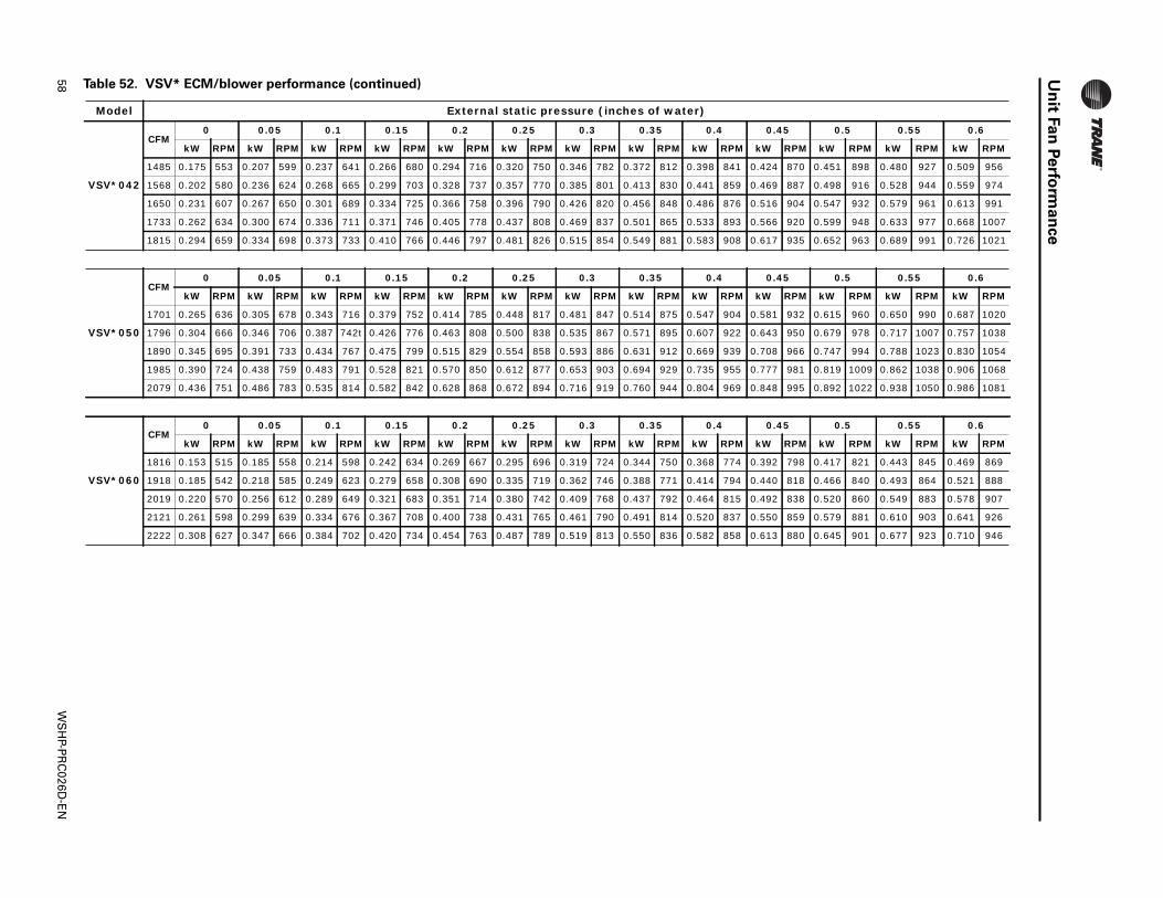
58W
SH
P-PR
C026D
-EN
Un
itFan
Perfo
rman
ce
CFM0 0.05 0.1 0.15 0.2 0.25 0.3 0.35 0.4 0.45 0.5 0.55 0.6
kW RPM kW RPM kW RPM kW RPM kW RPM kW RPM kW RPM kW RPM kW RPM kW RPM kW RPM kW RPM kW RPM
1 898 0.480 927 0.509 956
8 916 0.528 944 0.559 974
7 932 0.579 961 0.613 991
9 948 0.633 977 0.668 1007
2 963 0.689 991 0.726 1021
0.5 0.55 0.6
RPM kW RPM kW RPM
5 960 0.650 990 0.687 1020
9 978 0.717 1007 0.757 1038
7 994 0.788 1023 0.830 1054
9 1009 0.862 1038 0.906 1068
2 1022 0.938 1050 0.986 1081
0.5 0.55 0.6
RPM kW RPM kW RPM
7 821 0.443 845 0.469 869
6 840 0.493 864 0.521 888
0 860 0.549 883 0.578 907
9 881 0.610 903 0.641 926
5 901 0.677 923 0.710 946
Table 52. VSV* ECM/blower performance (continued)
Model External static pressure (inches of water)
VSV*042
1485 0.175 553 0.207 599 0.237 641 0.266 680 0.294 716 0.320 750 0.346 782 0.372 812 0.398 841 0.424 870 0.45
1568 0.202 580 0.236 624 0.268 665 0.299 703 0.328 737 0.357 770 0.385 801 0.413 830 0.441 859 0.469 887 0.49
1650 0.231 607 0.267 650 0.301 689 0.334 725 0.366 758 0.396 790 0.426 820 0.456 848 0.486 876 0.516 904 0.54
1733 0.262 634 0.300 674 0.336 711 0.371 746 0.405 778 0.437 808 0.469 837 0.501 865 0.533 893 0.566 920 0.59
1815 0.294 659 0.334 698 0.373 733 0.410 766 0.446 797 0.481 826 0.515 854 0.549 881 0.583 908 0.617 935 0.65
VSV*050
CFM0 0.05 0.1 0.15 0.2 0.25 0.3 0.35 0.4 0.45
kW RPM kW RPM kW RPM kW RPM kW RPM kW RPM kW RPM kW RPM kW RPM kW RPM kW
1701 0.265 636 0.305 678 0.343 716 0.379 752 0.414 785 0.448 817 0.481 847 0.514 875 0.547 904 0.581 932 0.61
1796 0.304 666 0.346 706 0.387 742t 0.426 776 0.463 808 0.500 838 0.535 867 0.571 895 0.607 922 0.643 950 0.67
1890 0.345 695 0.391 733 0.434 767 0.475 799 0.515 829 0.554 858 0.593 886 0.631 912 0.669 939 0.708 966 0.74
1985 0.390 724 0.438 759 0.483 791 0.528 821 0.570 850 0.612 877 0.653 903 0.694 929 0.735 955 0.777 981 0.81
2079 0.436 751 0.486 783 0.535 814 0.582 842 0.628 868 0.672 894 0.716 919 0.760 944 0.804 969 0.848 995 0.89
VSV*060
CFM0 0.05 0.1 0.15 0.2 0.25 0.3 0.35 0.4 0.45
kW RPM kW RPM kW RPM kW RPM kW RPM kW RPM kW RPM kW RPM kW RPM kW RPM kW
1816 0.153 515 0.185 558 0.214 598 0.242 634 0.269 667 0.295 696 0.319 724 0.344 750 0.368 774 0.392 798 0.41
1918 0.185 542 0.218 585 0.249 623 0.279 658 0.308 690 0.335 719 0.362 746 0.388 771 0.414 794 0.440 818 0.46
2019 0.220 570 0.256 612 0.289 649 0.321 683 0.351 714 0.380 742 0.409 768 0.437 792 0.464 815 0.492 838 0.52
2121 0.261 598 0.299 639 0.334 676 0.367 708 0.400 738 0.431 765 0.461 790 0.491 814 0.520 837 0.550 859 0.57
2222 0.308 627 0.347 666 0.384 702 0.420 734 0.454 763 0.487 789 0.519 813 0.550 836 0.582 858 0.613 880 0.64

WS
HP-P
RC
026D-E
N59
Un
itFan
Perfo
rma
nce
Table 53. VSV*024 plenum fan performance
Model External static pressure (inches of water)
0.0 0.1 0.2 0.3 0.4 0.5 0.6 0.7 0.8 0.9 1.0
kW RPM kW RPM
0.237 1217 0.254 1262
0.246 1231 0.264 1276
0.255 1246 0.274 1290
0.265 1261 0.284 1304
0.275 1276 0.294 1319
2.0 2.1
kW RPM kW RPM
0.456 1634 0.478 1666
0.470 1645 0.494 1677
0.485 1656 0.509 1688
0.500 1667 0.525 1699
0.516 1678 0.540 1710
VSV*024
CFM kW RPM kW RPM kW RPM kW RPM kW RPM kW RPM kW RPM kW RPM kW RPM
847 0.100 691 0.114 762 0.127 829 0.141 892 0.156 953 0.171 1011 0.187 1066 0.203 1119 0.220 1169
889 0.105 713 0.119 782 0.133 848 0.148 911 0.163 971 0.179 1028 0.195 1083 0.211 1134 0.228 1184
930 0.110 735 0.124 803 0.139 869 0.154 931 0.170 990 0.186 1046 0.203 1099 0.220 1150 0.237 1199
971 0.115 757 0.130 825 0.145 889 0.161 950 0.177 1008 0.193 1063 0.211 1116 0.228 1167 0.246 1215
1012 0.120 780 0.135 846 0.151 909 0.167 969 0.184 1027 0.201 1081 0.219 1133 0.237 1183 0.256 1230
VSV*024
CFM
1.1 1.2 1.3 1.4 1.5 1.6 1.7 1.8 1.9
kW RPM kW RPM kW RPM kW RPM kW RPM kW RPM kW RPM kW RPM kW RPM
847 0.272 1306 0.291 1348 0.310 1388 0.329 1426 0.349 1464 0.369 1500 0.390 1535 0.412 1569 0.433 1602
889 0.283 1319 0.301 1361 0.321 1400 0.341 1438 0.361 1475 0.382 1511 0.403 1546 0.425 1579 0.448 1612
930 0.293 1333 0.312 1374 0.332 1413 0.353 1451 0.374 1487 0.395 1523 0.417 1557 0.439 1591 0.462 1623
971 0.303 1347 0.323 1387 0.344 1426 0.365 1463 0.386 1499 0.408 1534 0.430 1569 0.453 1602 0.477 1635
1012 0.314 1360 0.335 1400 0.356 1439 0.377 1476 0.399 1512 0.421 1546 0.444 1580 0.468 1614 0.491 1646
VSV*024
CFM
2.2 2.3 2.4 2.5
kW RPM kW RPM kW RPM kW RPM
847 0.501 1698 0.525 1730 0.549 1761 0.574 1793
889 0.517 1709 0.541 1740 0.566 1772 0.591 1804
930 0.533 1720 0.558 1751 0.583 1783 0.609 1815
971 0.549 1731 0.574 1762 0.600 1794 0.626 1826
1012 0.566 1742 0.591 1774 0.617 1806 0.644 1838
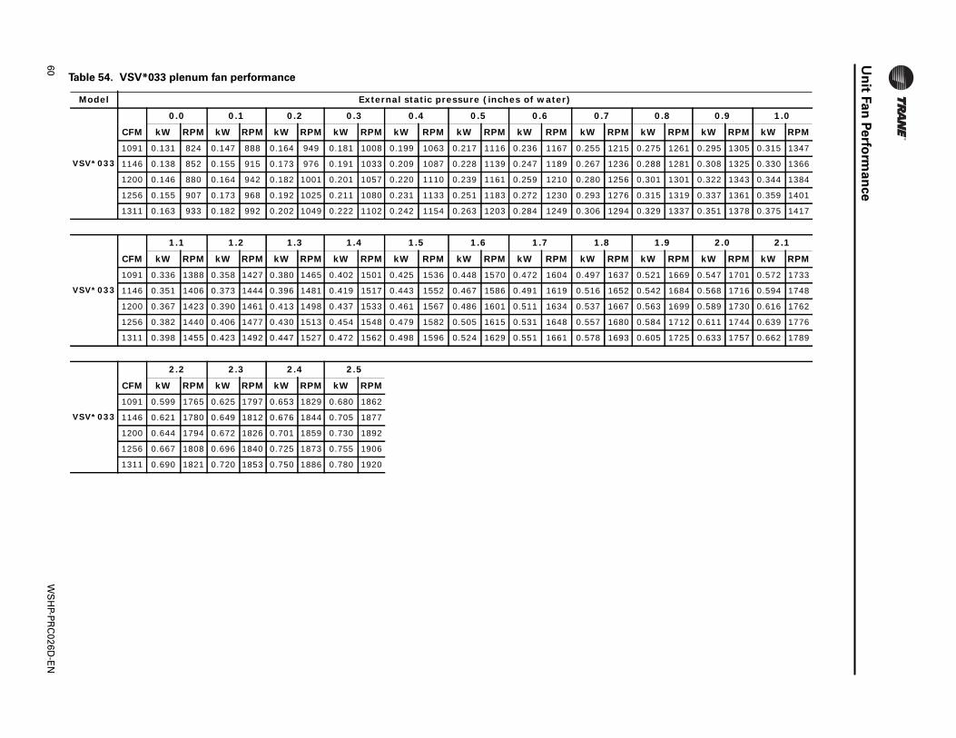
60W
SH
P-PR
C026D
-EN
Un
itFan
Perfo
rman
ce
Table 54. VSV*033 plenum fan performance
Model External static pressure (inches of water)
0.0 0.1 0.2 0.3 0.4 0.5 0.6 0.7 0.8 0.9 1.0
kW RPM kW RPM
0.295 1305 0.315 1347
0.308 1325 0.330 1366
0.322 1343 0.344 1384
0.337 1361 0.359 1401
0.351 1378 0.375 1417
2.0 2.1
kW RPM kW RPM
0.547 1701 0.572 1733
0.568 1716 0.594 1748
0.589 1730 0.616 1762
0.611 1744 0.639 1776
0.633 1757 0.662 1789
VSV*033
CFM kW RPM kW RPM kW RPM kW RPM kW RPM kW RPM kW RPM kW RPM kW RPM
1091 0.131 824 0.147 888 0.164 949 0.181 1008 0.199 1063 0.217 1116 0.236 1167 0.255 1215 0.275 1261
1146 0.138 852 0.155 915 0.173 976 0.191 1033 0.209 1087 0.228 1139 0.247 1189 0.267 1236 0.288 1281
1200 0.146 880 0.164 942 0.182 1001 0.201 1057 0.220 1110 0.239 1161 0.259 1210 0.280 1256 0.301 1301
1256 0.155 907 0.173 968 0.192 1025 0.211 1080 0.231 1133 0.251 1183 0.272 1230 0.293 1276 0.315 1319
1311 0.163 933 0.182 992 0.202 1049 0.222 1102 0.242 1154 0.263 1203 0.284 1249 0.306 1294 0.329 1337
VSV*033
CFM
1.1 1.2 1.3 1.4 1.5 1.6 1.7 1.8 1.9
kW RPM kW RPM kW RPM kW RPM kW RPM kW RPM kW RPM kW RPM kW RPM
1091 0.336 1388 0.358 1427 0.380 1465 0.402 1501 0.425 1536 0.448 1570 0.472 1604 0.497 1637 0.521 1669
1146 0.351 1406 0.373 1444 0.396 1481 0.419 1517 0.443 1552 0.467 1586 0.491 1619 0.516 1652 0.542 1684
1200 0.367 1423 0.390 1461 0.413 1498 0.437 1533 0.461 1567 0.486 1601 0.511 1634 0.537 1667 0.563 1699
1256 0.382 1440 0.406 1477 0.430 1513 0.454 1548 0.479 1582 0.505 1615 0.531 1648 0.557 1680 0.584 1712
1311 0.398 1455 0.423 1492 0.447 1527 0.472 1562 0.498 1596 0.524 1629 0.551 1661 0.578 1693 0.605 1725
VSV*033
CFM
2.2 2.3 2.4 2.5
kW RPM kW RPM kW RPM kW RPM
1091 0.599 1765 0.625 1797 0.653 1829 0.680 1862
1146 0.621 1780 0.649 1812 0.676 1844 0.705 1877
1200 0.644 1794 0.672 1826 0.701 1859 0.730 1892
1256 0.667 1808 0.696 1840 0.725 1873 0.755 1906
1311 0.690 1821 0.720 1853 0.750 1886 0.780 1920

WS
HP-P
RC
026D-E
N61
Un
itFan
Perfo
rma
nce
Table 55. VSV*042 plenum fan performance
Model External static pressure (inches of water)
0.0 0.1 0.2 0.3 0.4 0.5 0.6 0.7 0.8 0.9 1.0
kW RPM kW RPM
0.350 1331 0.376 1373
0.372 1362 0.399 1403
0.389 1385 0.416 1425
0.406 1409 0.434 1447
0.429 1440 0.458 1477
2.0 2.1
kW RPM kW RPM
0.648 1731 0.675 1763
0.678 1754 0.706 1786
0.701 1772 0.729 1804
0.724 1790 0.753 1822
0.755 1814 0.784 1846
VSV*042
CFM kW RPM kW RPM kW RPM kW RPM kW RPM kW RPM kW RPM kW RPM kW RPM
1491 0.148 883 0.167 940 0.187 996 0.208 1049 0.230 1100 0.252 1150 0.276 1198 0.300 1244 0.325 1288
1581 0.161 929 0.181 985 0.202 1038 0.224 1089 0.247 1139 0.270 1186 0.295 1233 0.320 1277 0.346 1320
1650 0.171 964 0.192 1018 0.214 1070 0.236 1119 0.260 1168 0.285 1214 0.310 1259 0.335 1302 0.362 1344
1717 0.182 999 0.203 1051 0.226 1101 0.249 1150 0.274 1197 0.299 1242 0.325 1285 0.351 1328 0.378 1369
1807 0.197 1046 0.219 1096 0.243 1144 0.267 1190 0.293 1235 0.319 1279 0.345 1321 0.373 1362 0.401 1401
VSV*042
CFM
1.1 1.2 1.3 1.4 1.5 1.6 1.7 1.8 1.9
kW RPM kW RPM kW RPM kW RPM kW RPM kW RPM kW RPM kW RPM kW RPM
1491 0.402 1414 0.429 1453 0.456 1491 0.483 1527 0.511 1563 0.538 1598 0.566 1633 0.593 1666 0.621 1699
1581 0.426 1442 0.453 1480 0.481 1517 0.509 1553 0.537 1588 0.566 1623 0.594 1656 0.622 1690 0.650 1722
1650 0.444 1463 0.472 1501 0.500 1537 0.529 1572 0.558 1607 0.587 1641 0.615 1675 0.644 1708 0.673 1740
1717 0.462 1485 0.491 1521 0.520 1557 0.549 1592 0.578 1626 0.608 1660 0.637 1693 0.666 1726 0.695 1758
1807 0.487 1514 0.516 1549 0.546 1584 0.576 1618 0.606 1652 0.636 1685 0.666 1718 0.696 1750 0.725 1782
VSV*042
CFM
2.2 2.3 2.4 2.5
kW RPM kW RPM kW RPM kW RPM
1491 0.702 1794 0.728 1826 0.754 1856 0.780 1887
1581 0.733 1818 0.760 1849 0.787 1880 0.813 1911
1650 0.757 1835 0.784 1867 0.811 1898 0.838 1930
1717 0.781 1853 0.809 1885 0.836 1917 0.863 1948
1807 0.813 1878 0.841 1909 0.869 1941 0.896 1974
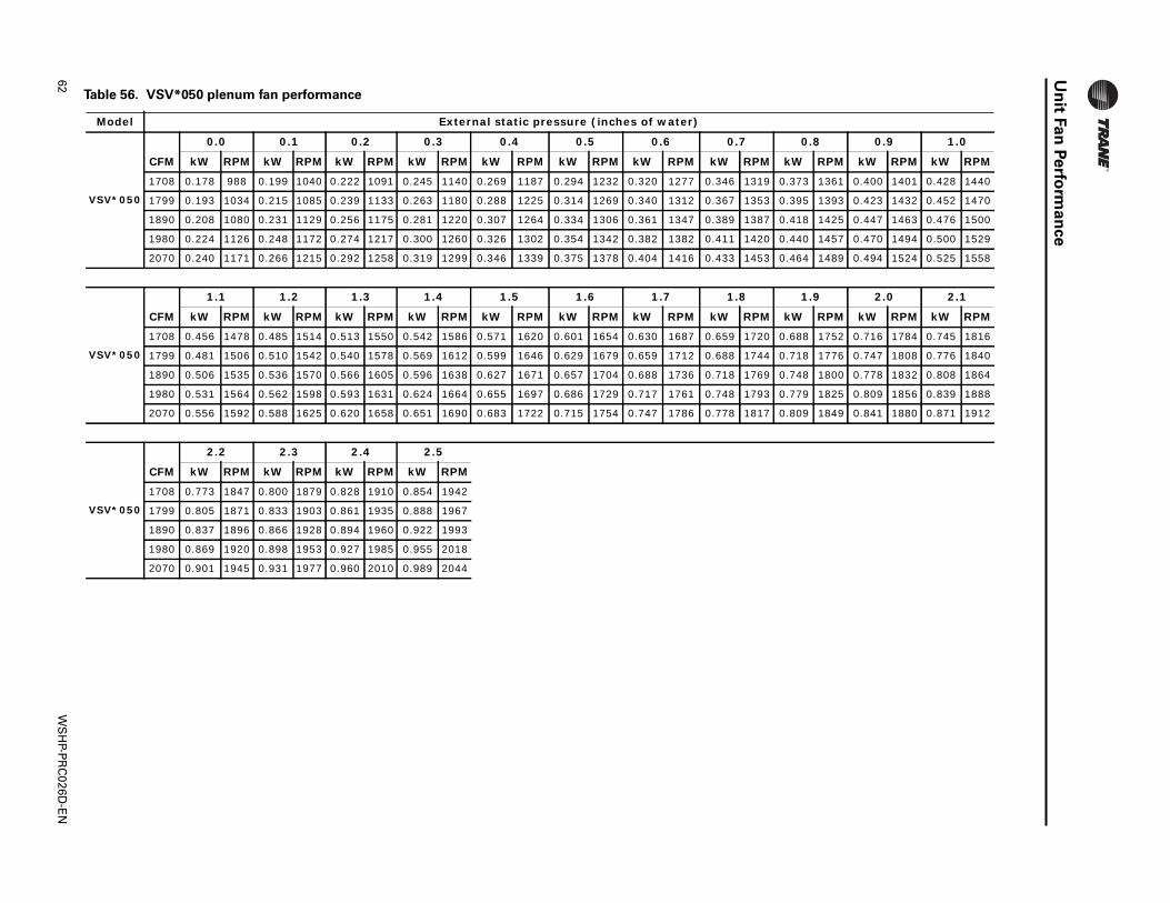
62W
SH
P-PR
C026D
-EN
Un
itFan
Perfo
rman
ce
Table 56. VSV*050 plenum fan performance
Model External static pressure (inches of water)
0.0 0.1 0.2 0.3 0.4 0.5 0.6 0.7 0.8 0.9 1.0
kW RPM kW RPM
0.400 1401 0.428 1440
0.423 1432 0.452 1470
0.447 1463 0.476 1500
0.470 1494 0.500 1529
0.494 1524 0.525 1558
2.0 2.1
kW RPM kW RPM
0.716 1784 0.745 1816
0.747 1808 0.776 1840
0.778 1832 0.808 1864
0.809 1856 0.839 1888
0.841 1880 0.871 1912
VSV*050
CFM kW RPM kW RPM kW RPM kW RPM kW RPM kW RPM kW RPM kW RPM kW RPM
1708 0.178 988 0.199 1040 0.222 1091 0.245 1140 0.269 1187 0.294 1232 0.320 1277 0.346 1319 0.373 1361
1799 0.193 1034 0.215 1085 0.239 1133 0.263 1180 0.288 1225 0.314 1269 0.340 1312 0.367 1353 0.395 1393
1890 0.208 1080 0.231 1129 0.256 1175 0.281 1220 0.307 1264 0.334 1306 0.361 1347 0.389 1387 0.418 1425
1980 0.224 1126 0.248 1172 0.274 1217 0.300 1260 0.326 1302 0.354 1342 0.382 1382 0.411 1420 0.440 1457
2070 0.240 1171 0.266 1215 0.292 1258 0.319 1299 0.346 1339 0.375 1378 0.404 1416 0.433 1453 0.464 1489
VSV*050
CFM
1.1 1.2 1.3 1.4 1.5 1.6 1.7 1.8 1.9
kW RPM kW RPM kW RPM kW RPM kW RPM kW RPM kW RPM kW RPM kW RPM
1708 0.456 1478 0.485 1514 0.513 1550 0.542 1586 0.571 1620 0.601 1654 0.630 1687 0.659 1720 0.688 1752
1799 0.481 1506 0.510 1542 0.540 1578 0.569 1612 0.599 1646 0.629 1679 0.659 1712 0.688 1744 0.718 1776
1890 0.506 1535 0.536 1570 0.566 1605 0.596 1638 0.627 1671 0.657 1704 0.688 1736 0.718 1769 0.748 1800
1980 0.531 1564 0.562 1598 0.593 1631 0.624 1664 0.655 1697 0.686 1729 0.717 1761 0.748 1793 0.779 1825
2070 0.556 1592 0.588 1625 0.620 1658 0.651 1690 0.683 1722 0.715 1754 0.747 1786 0.778 1817 0.809 1849
VSV*050
CFM
2.2 2.3 2.4 2.5
kW RPM kW RPM kW RPM kW RPM
1708 0.773 1847 0.800 1879 0.828 1910 0.854 1942
1799 0.805 1871 0.833 1903 0.861 1935 0.888 1967
1890 0.837 1896 0.866 1928 0.894 1960 0.922 1993
1980 0.869 1920 0.898 1953 0.927 1985 0.955 2018
2070 0.901 1945 0.931 1977 0.960 2010 0.989 2044
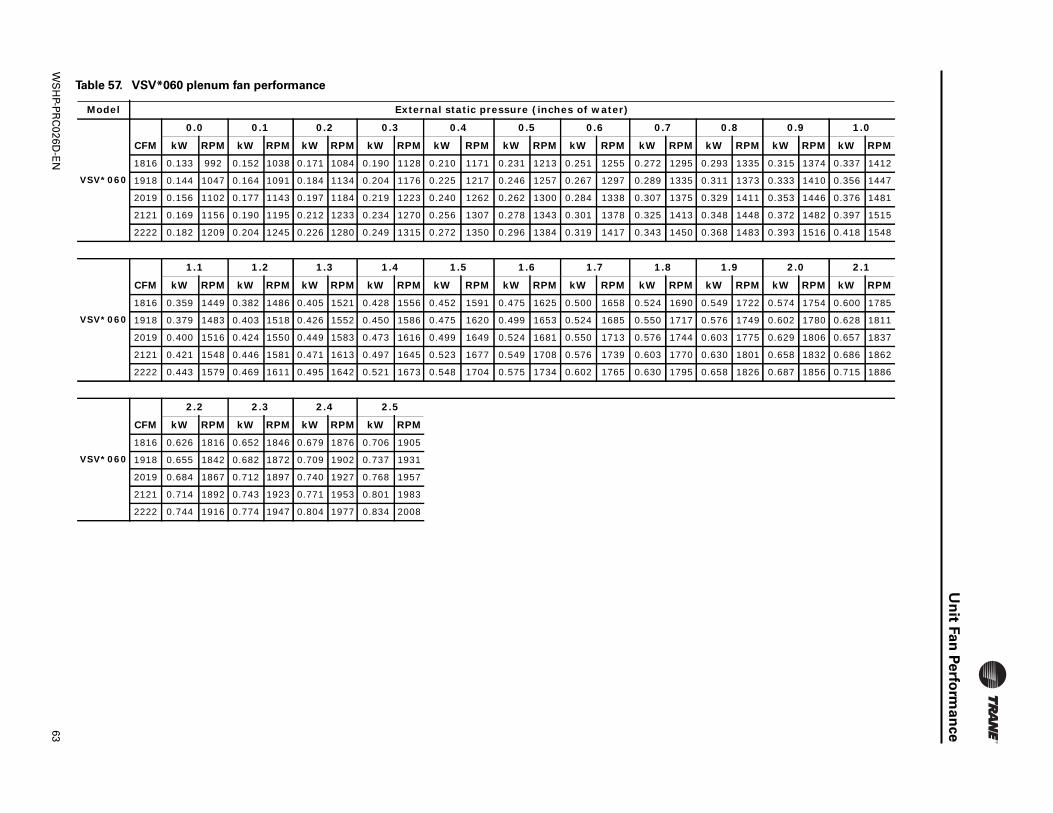
WS
HP-P
RC
026D-E
N63
Un
itFan
Perfo
rma
nce
Table 57. VSV*060 plenum fan performance
Model External static pressure (inches of water)
0.0 0.1 0.2 0.3 0.4 0.5 0.6 0.7 0.8 0.9 1.0
kW RPM kW RPM
0.315 1374 0.337 1412
0.333 1410 0.356 1447
0.353 1446 0.376 1481
0.372 1482 0.397 1515
0.393 1516 0.418 1548
2.0 2.1
kW RPM kW RPM
0.574 1754 0.600 1785
0.602 1780 0.628 1811
0.629 1806 0.657 1837
0.658 1832 0.686 1862
0.687 1856 0.715 1886
VSV*060
CFM kW RPM kW RPM kW RPM kW RPM kW RPM kW RPM kW RPM kW RPM kW RPM
1816 0.133 992 0.152 1038 0.171 1084 0.190 1128 0.210 1171 0.231 1213 0.251 1255 0.272 1295 0.293 1335
1918 0.144 1047 0.164 1091 0.184 1134 0.204 1176 0.225 1217 0.246 1257 0.267 1297 0.289 1335 0.311 1373
2019 0.156 1102 0.177 1143 0.197 1184 0.219 1223 0.240 1262 0.262 1300 0.284 1338 0.307 1375 0.329 1411
2121 0.169 1156 0.190 1195 0.212 1233 0.234 1270 0.256 1307 0.278 1343 0.301 1378 0.325 1413 0.348 1448
2222 0.182 1209 0.204 1245 0.226 1280 0.249 1315 0.272 1350 0.296 1384 0.319 1417 0.343 1450 0.368 1483
VSV*060
CFM
1.1 1.2 1.3 1.4 1.5 1.6 1.7 1.8 1.9
kW RPM kW RPM kW RPM kW RPM kW RPM kW RPM kW RPM kW RPM kW RPM
1816 0.359 1449 0.382 1486 0.405 1521 0.428 1556 0.452 1591 0.475 1625 0.500 1658 0.524 1690 0.549 1722
1918 0.379 1483 0.403 1518 0.426 1552 0.450 1586 0.475 1620 0.499 1653 0.524 1685 0.550 1717 0.576 1749
2019 0.400 1516 0.424 1550 0.449 1583 0.473 1616 0.499 1649 0.524 1681 0.550 1713 0.576 1744 0.603 1775
2121 0.421 1548 0.446 1581 0.471 1613 0.497 1645 0.523 1677 0.549 1708 0.576 1739 0.603 1770 0.630 1801
2222 0.443 1579 0.469 1611 0.495 1642 0.521 1673 0.548 1704 0.575 1734 0.602 1765 0.630 1795 0.658 1826
VSV*060
CFM
2.2 2.3 2.4 2.5
kW RPM kW RPM kW RPM kW RPM
1816 0.626 1816 0.652 1846 0.679 1876 0.706 1905
1918 0.655 1842 0.682 1872 0.709 1902 0.737 1931
2019 0.684 1867 0.712 1897 0.740 1927 0.768 1957
2121 0.714 1892 0.743 1923 0.771 1953 0.801 1983
2222 0.744 1916 0.774 1947 0.804 1977 0.834 2008
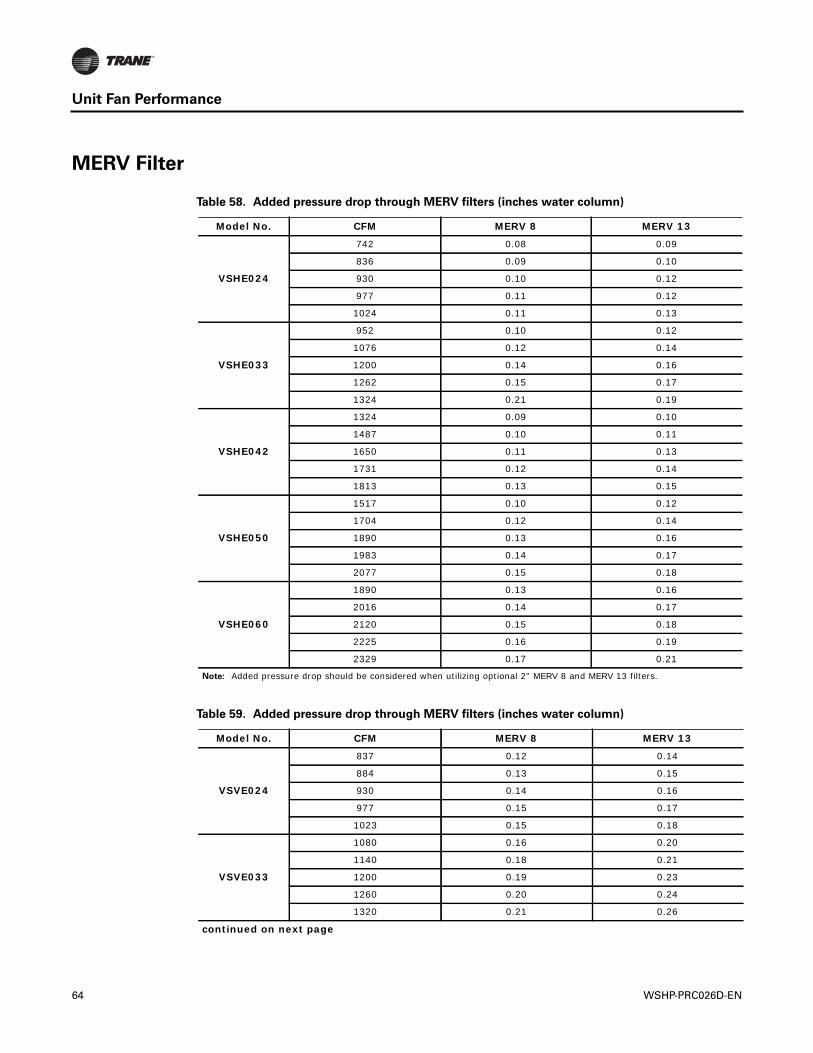
Unit Fan Performance
MERV Filter
Table 58. Added pressure drop through MERV filters (inches water column)
Model No. CFM MERV 8 MERV 13
VSHE024
742 0.08 0.09
836 0.09 0.10
930 0.10 0.12
977 0.11 0.12
1024 0.11 0.13
VSHE033
952 0.10 0.12
1076 0.12 0.14
1200 0.14 0.16
1262 0.15 0.17
1324 0.21 0.19
VSHE042
1324 0.09 0.10
1487 0.10 0.11
1650 0.11 0.13
1731 0.12 0.14
1813 0.13 0.15
VSHE050
1517 0.10 0.12
1704 0.12 0.14
1890 0.13 0.16
1983 0.14 0.17
2077 0.15 0.18
VSHE060
1890 0.13 0.16
2016 0.14 0.17
2120 0.15 0.18
2225 0.16 0.19
2329 0.17 0.21
Note: Added pressure drop should be considered when utilizing optional 2" MERV 8 and MERV 13 filters.
Table 59. Added pressure drop through MERV filters (inches water column)
Model No. CFM MERV 8 MERV 13
VSVE024
837 0.12 0.14
884 0.13 0.15
930 0.14 0.16
977 0.15 0.17
1023 0.15 0.18
VSVE033
1080 0.16 0.20
1140 0.18 0.21
1200 0.19 0.23
1260 0.20 0.24
1320 0.21 0.26
continued on next page
64 WSHP-PRC026D-EN
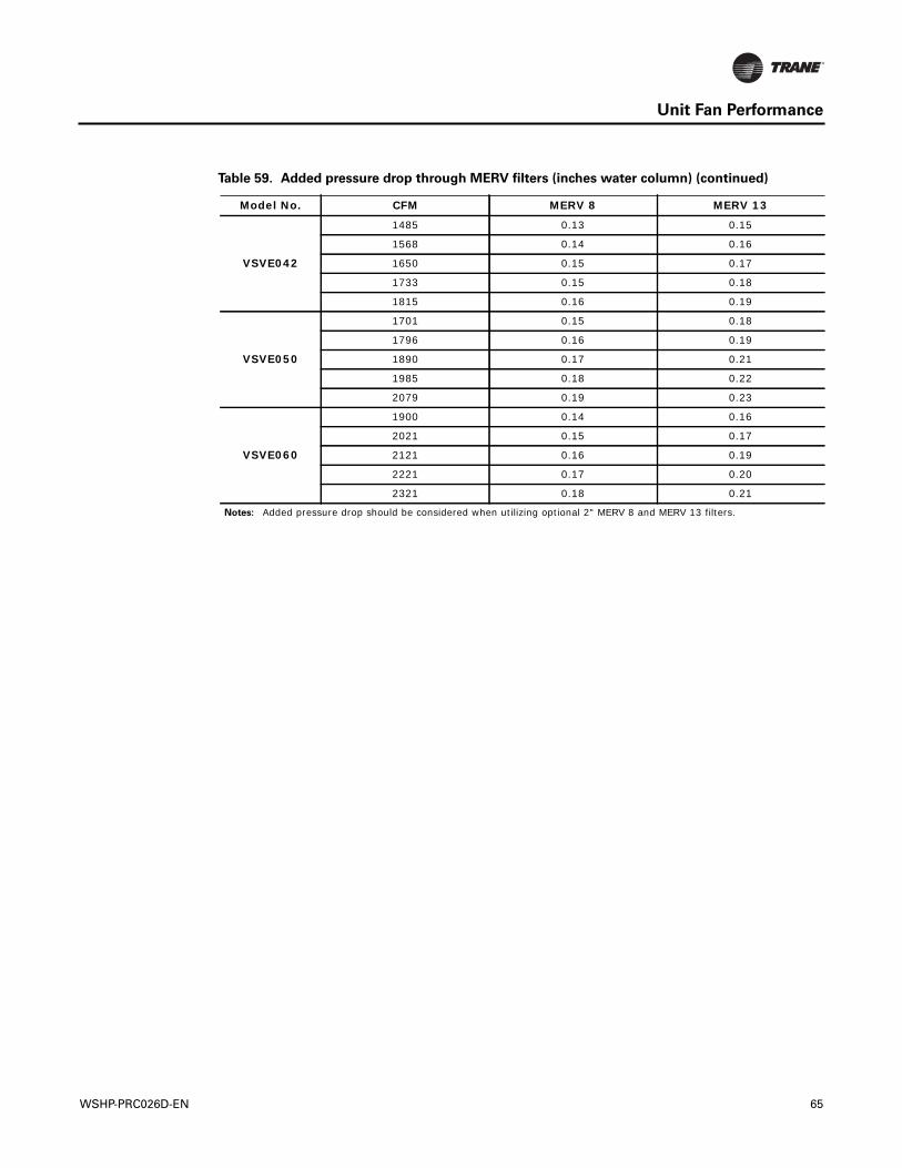
Unit Fan Performance
VSVE042
1485 0.13 0.15
1568 0.14 0.16
1650 0.15 0.17
1733 0.15 0.18
1815 0.16 0.19
VSVE050
1701 0.15 0.18
1796 0.16 0.19
1890 0.17 0.21
1985 0.18 0.22
2079 0.19 0.23
VSVE060
1900 0.14 0.16
2021 0.15 0.17
2121 0.16 0.19
2221 0.17 0.20
2321 0.18 0.21
Notes: Added pressure drop should be considered when utilizing optional 2" MERV 8 and MERV 13 filters.
Table 59. Added pressure drop through MERV filters (inches water column) (continued)
Model No. CFM MERV 8 MERV 13
WSHP-PRC026D-EN 65
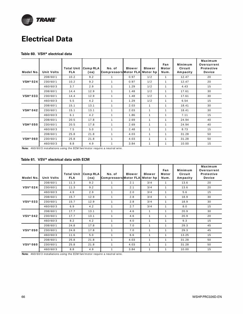
Electrical Data
Table 60. VSH* electrical data
Model No. Unit VoltsTotal Unit
FLAComp RLA
(ea)No. of
CompressorsBlower
Motor FLABlower
Motor hp
Fan Motor Num.
Minimum Circuit
Ampacity
Maximum Overcurrent Protective
Device
VSH*024208/60/1 10.2 9.2 1 0.97 1/2 1 12.47 20
230/60/1 10.2 9.2 1 0.97 1/2 1 12.47 20
460/60/3 3.7 2.9 1 1.29 1/2 1 4.43 15
VSH*033208/60/1 14.4 12.9 1 1.48 1/2 1 17.61 30
230/60/1 14.4 12.9 1 1.48 1/2 1 17.61 30
460/60/3 5.5 4.2 1 1.29 1/2 1 6.54 15
VSH*042208/60/1 15.1 13.1 1 2.03 1 1 18.41 30
230/60/1 15.1 13.1 1 2.03 1 1 18.41 30
460/60/3 6.1 4.2 1 1.86 1 1 7.11 15
VSH*050208/60/1 20.5 17.8 1 2.69 1 1 24.94 40
230/60/1 20.5 17.8 1 2.69 1 1 24.94 40
460/60/3 7.5 5.0 1 2.48 1 1 8.73 15
VSH*060208/60/1 25.8 21.8 1 4.03 1 1 31.28 50
230/60/1 25.8 21.8 1 4.03 1 1 31.28 50
460/60/3 8.8 4.9 1 3.84 1 1 10.00 15
Note: 460/60/3 installations using the ECM fan/motor require a neutral wire.
Table 61. VSV* electrical data with ECM
Model No. Unit VoltsTotal Unit
FLAComp RLA
(ea)No. of
CompressorsBlower
Motor FLABlower
Motor hp
Fan Motor Num.
Minimum Circuit
Ampacity
Maximum Overcurrent Protective
Device
VSV*024208/60/1 11.3 9.2 1 2.1 3/4 1 13.6 20
230/60/1 11.3 9.2 1 2.1 3/4 1 13.6 20
460/60/3 4.9 2.9 1 2.0 3/4 1 5.6 15
VSV*033208/60/1 15.7 12.9 1 2.8 3/4 1 18.9 30
230/60/1 15.7 12.9 1 2.8 3/4 1 18.9 30
460/60/3 6.9 4.2 1 2.7 3/4 1 8.0 15
VSV*042208/60/1 17.7 13.1 1 4.6 1 1 20.9 30
230/60/1 17.7 13.1 1 4.6 1 1 20.9 20
460/60/3 8.2 4.2 1 4.0 1 1 9.3 15
VSV*050208/60/1 24.8 17.8 1 7.0 1 1 29.3 45
230/60/1 24.8 17.8 1 7.0 1 1 29.3 45
460/60/3 11.6 5.0 1 6.6 1 1 13.25 15
VSV*060208/60/1 25.8 21.8 1 4.03 1 1 31.28 50
230/60/1 25.8 21.8 1 4.03 1 1 31.28 50
460/60/3 8.8 4.9 1 3.84 1 1 10.00 15
Note: 460/60/3 installations using the ECM fan/motor require a neutral wire.
66 WSHP-PRC026D-EN
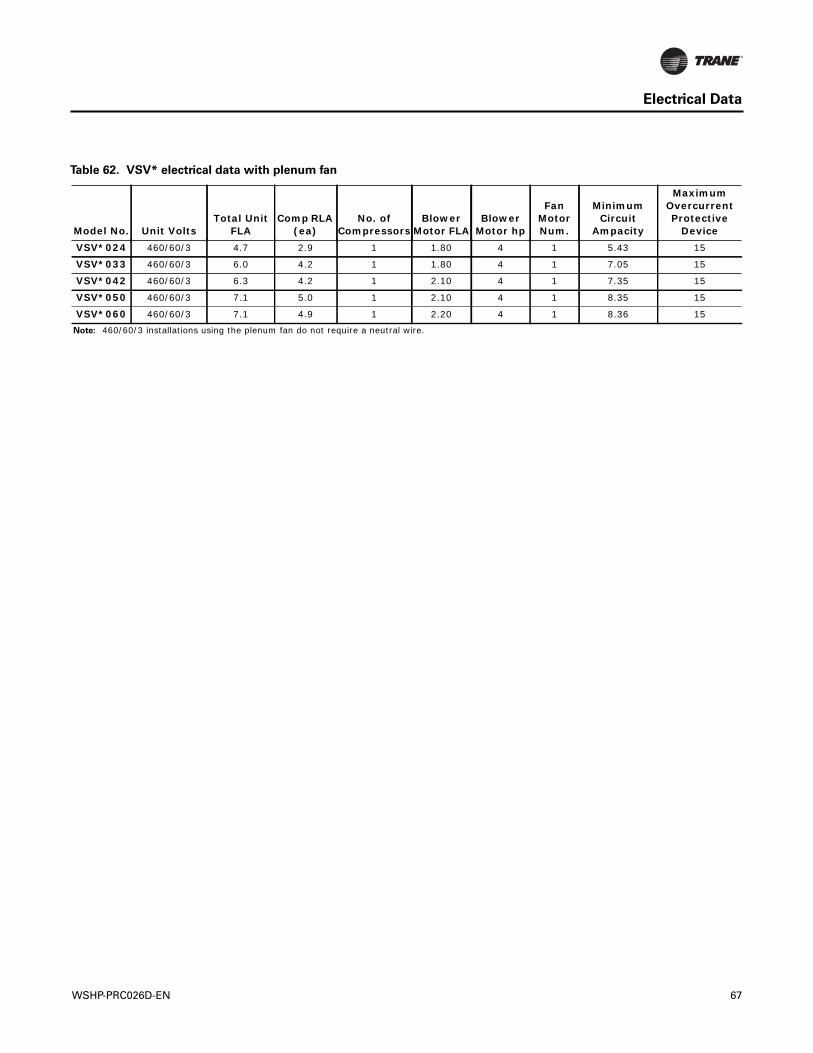
Electrical Data
Table 62. VSV* electrical data with plenum fan
Model No. Unit VoltsTotal Unit
FLAComp RLA
(ea)No. of
CompressorsBlower
Motor FLABlower
Motor hp
Fan Motor Num.
Minimum Circuit
Ampacity
Maximum Overcurrent Protective
DeviceVSV*024 460/60/3 4.7 2.9 1 1.80 4 1 5.43 15
VSV*033 460/60/3 6.0 4.2 1 1.80 4 1 7.05 15
VSV*042 460/60/3 6.3 4.2 1 2.10 4 1 7.35 15
VSV*050 460/60/3 7.1 5.0 1 2.10 4 1 8.35 15
VSV*060 460/60/3 7.1 4.9 1 2.20 4 1 8.36 15
Note: 460/60/3 installations using the plenum fan do not require a neutral wire.
WSHP-PRC026D-EN 67
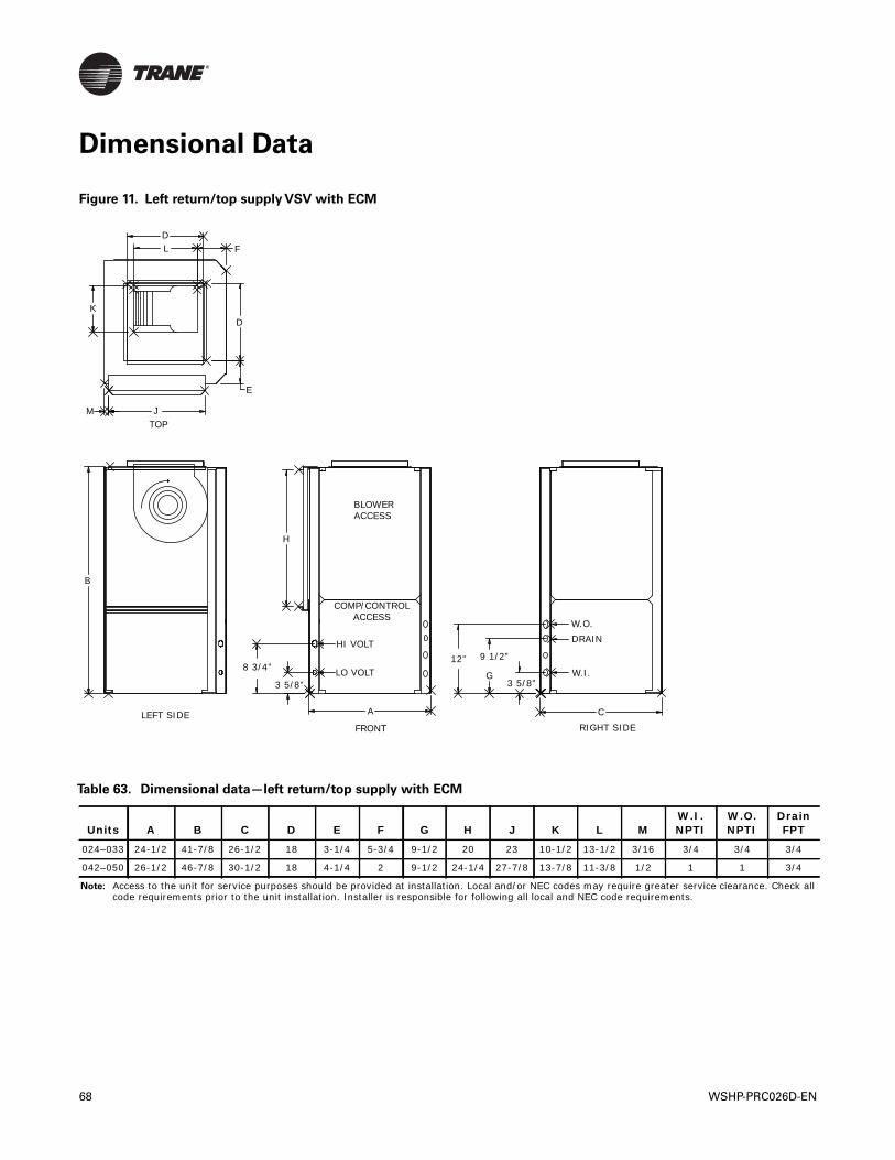
Dimensional Data
Figure 11. Left return/top supply VSV with ECM
DL F
DK
M J
E
TOP
B
H
BLOWERACCESS
COMP/CONTROLACCESS
HI VOLT
LO VOLT
ALEFT SIDEFRONT
C
RIGHT SIDE
W.I.
DRAINW.O.
8 3/4”
3 5/8”
12” 9 1/2”
G3 5/8”
Table 63. Dimensional data—left return/top supply with ECM
Units A B C D E F G H J K L MW.I. NPTI
W.O. NPTI
Drain FPT
024–033 24-1/2 41-7/8 26-1/2 18 3-1/4 5-3/4 9-1/2 20 23 10-1/2 13-1/2 3/16 3/4 3/4 3/4
042–050 26-1/2 46-7/8 30-1/2 18 4-1/4 2 9-1/2 24-1/4 27-7/8 13-7/8 11-3/8 1/2 1 1 3/4
Note: Access to the unit for service purposes should be provided at installation. Local and/or NEC codes may require greater service clearance. Check all code requirements prior to the unit installation. Installer is responsible for following all local and NEC code requirements.
68 WSHP-PRC026D-EN
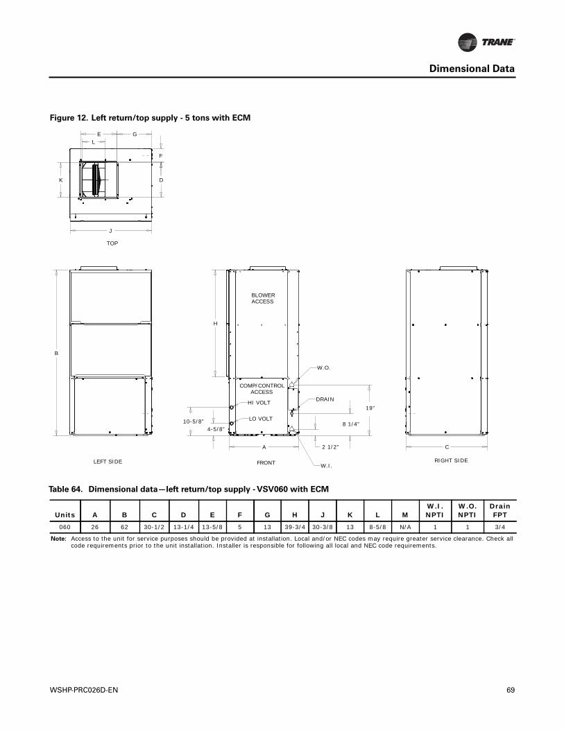
Dimensional Data
Figure 12. Left return/top supply - 5 tons with ECM
D
EL
K
J
H
4-5/8”10-5/8”
A
B
C2 1/2”
8 1/4”
19”
G
F
BLOWERACCESS
COMP/CONTROLACCESS
TOP
LEFT SIDE FRONT RIGHT SIDE
HI VOLT
LO VOLT
W.O.
W.I.
DRAIN
Table 64. Dimensional data—left return/top supply - VSV060 with ECM
Units A B C D E F G H J K L MW.I. NPTI
W.O. NPTI
Drain FPT
060 26 62 30-1/2 13-1/4 13-5/8 5 13 39-3/4 30-3/8 13 8-5/8 N/A 1 1 3/4
Note: Access to the unit for service purposes should be provided at installation. Local and/or NEC codes may require greater service clearance. Check all code requirements prior to the unit installation. Installer is responsible for following all local and NEC code requirements.
WSHP-PRC026D-EN 69
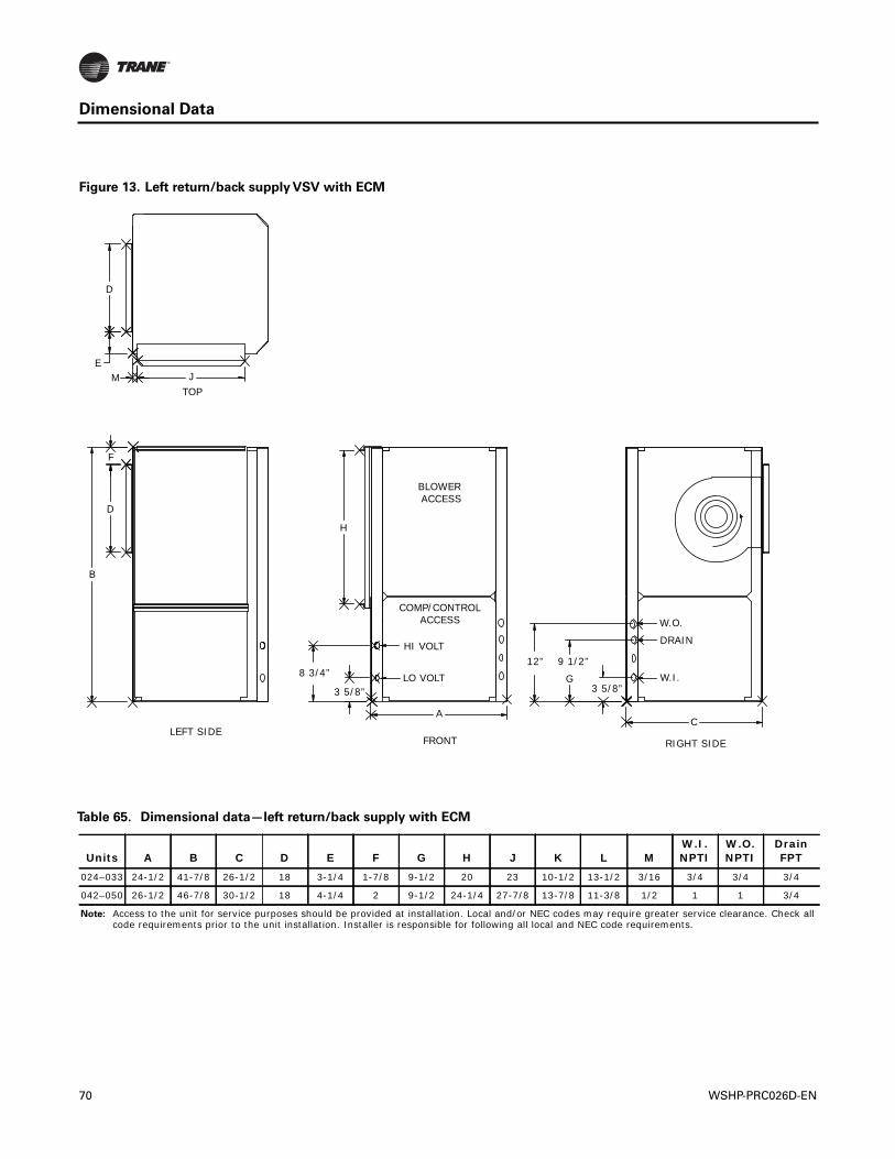
Dimensional Data
Figure 13. Left return/back supply VSV with ECM
D
EM J
TOP
F
D
B
H
BLOWER ACCESS
COMP/CONTROLACCESS
HI VOLT
LO VOLT
LEFT SIDE
8 3/4”
3 5/8”
A
FRONT RIGHT SIDE
C
W.O.
DRAIN
W.I.12” 9 1/2”
G3 5/8”
Table 65. Dimensional data—left return/back supply with ECM
Units A B C D E F G H J K L MW.I. NPTI
W.O. NPTI
Drain FPT
024–033 24-1/2 41-7/8 26-1/2 18 3-1/4 1-7/8 9-1/2 20 23 10-1/2 13-1/2 3/16 3/4 3/4 3/4
042–050 26-1/2 46-7/8 30-1/2 18 4-1/4 2 9-1/2 24-1/4 27-7/8 13-7/8 11-3/8 1/2 1 1 3/4
Note: Access to the unit for service purposes should be provided at installation. Local and/or NEC codes may require greater service clearance. Check all code requirements prior to the unit installation. Installer is responsible for following all local and NEC code requirements.
70 WSHP-PRC026D-EN
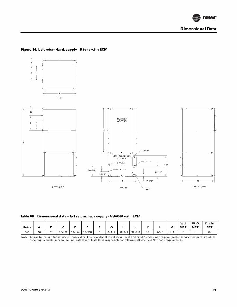
Dimensional Data
Figure 14. Left return/back supply - 5 tons with ECM
H
4-5/8”
10-5/8”
A
B
C2 1/2”
8 1/4”
19”
E
G
L
J
D K
F
BLOWERACCESS
COMP/CONTROLACCESS
TOP
LEFT SIDE FRONT RIGHT SIDE
HI VOLT
LO VOLT
W.O.
W.I.
DRAIN
Table 66. Dimensional data—left return/back supply - VSV060 with ECM
Units A B C D E F G H J K L MW.I. NPTI
W.O. NPTI
Drain FPT
060 26 62 30-1/2 13-1/4 13-5/8 5 6-1/2 39-3/4 30-3/8 13 8-5/8 N/A 1 1 3/4
Note: Access to the unit for service purposes should be provided at installation. Local and/or NEC codes may require greater service clearance. Check all code requirements prior to the unit installation. Installer is responsible for following all local and NEC code requirements.
WSHP-PRC026D-EN 71
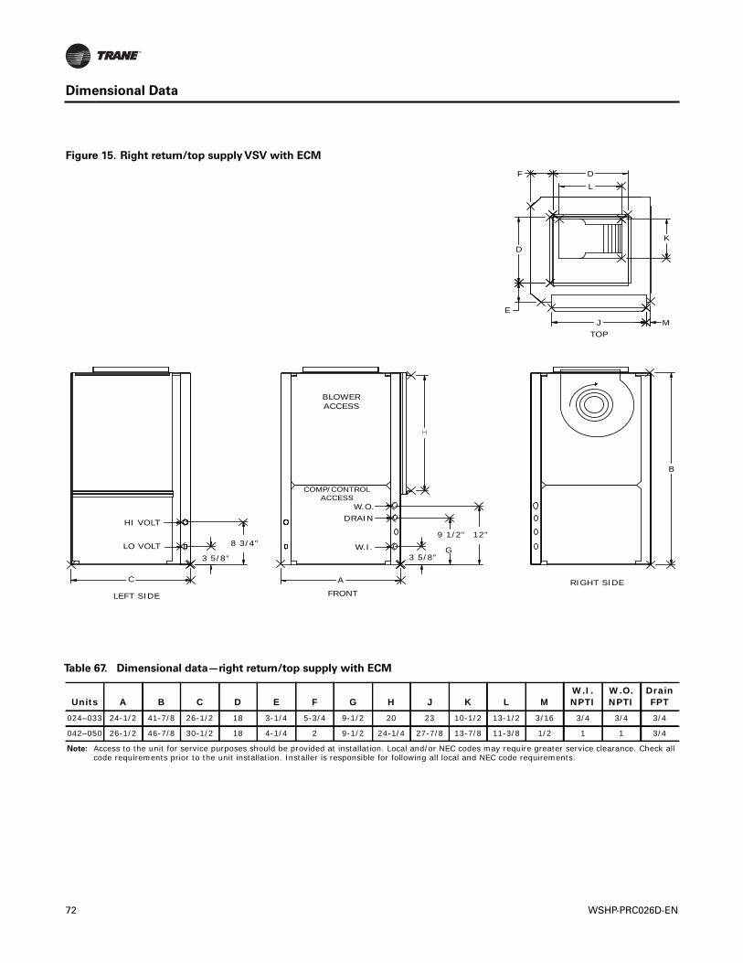
Dimensional Data
Figure 15. Right return/top supply VSV with ECM
H
HI VOLT
LO VOLT
LEFT SIDE
C
3 5/8”
8 3/4”
BLOWERACCESS
COMP/CONTROLACCESS
W.O.DRAIN
W.I.
A
FRONT
3 5/8”
9 1/2”
G
12”
RIGHT SIDE
B
F D
L
D
E
K
MJTOP
Table 67. Dimensional data—right return/top supply with ECM
Units A B C D E F G H J K L MW.I. NPTI
W.O. NPTI
Drain FPT
024–033 24-1/2 41-7/8 26-1/2 18 3-1/4 5-3/4 9-1/2 20 23 10-1/2 13-1/2 3/16 3/4 3/4 3/4
042–050 26-1/2 46-7/8 30-1/2 18 4-1/4 2 9-1/2 24-1/4 27-7/8 13-7/8 11-3/8 1/2 1 1 3/4
Note: Access to the unit for service purposes should be provided at installation. Local and/or NEC codes may require greater service clearance. Check all code requirements prior to the unit installation. Installer is responsible for following all local and NEC code requirements.
72 WSHP-PRC026D-EN
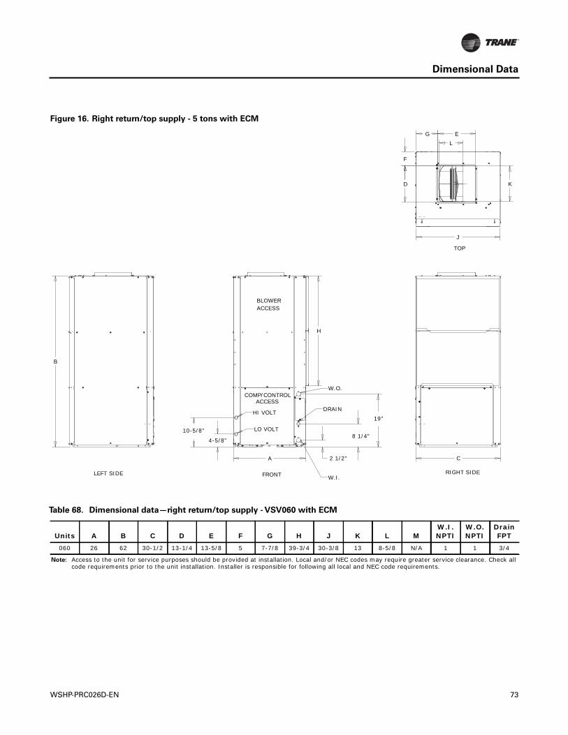
Dimensional Data
Figure 16. Right return/top supply - 5 tons with ECM
H
4-5/8”
10-5/8”
A
B
C2 1/2"
8 1/4"
19”
J
L
K
F
D
G E
BLOWERACCESS
COMP/CONTROLACCESS
TOP
LEFT SIDE FRONT RIGHT SIDE
HI VOLT
LO VOLT
W.O.
W.I.
DRAIN
Table 68. Dimensional data—right return/top supply - VSV060 with ECM
Units A B C D E F G H J K L MW.I. NPTI
W.O. NPTI
Drain FPT
060 26 62 30-1/2 13-1/4 13-5/8 5 7-7/8 39-3/4 30-3/8 13 8-5/8 N/A 1 1 3/4
Note: Access to the unit for service purposes should be provided at installation. Local and/or NEC codes may require greater service clearance. Check all code requirements prior to the unit installation. Installer is responsible for following all local and NEC code requirements.
WSHP-PRC026D-EN 73
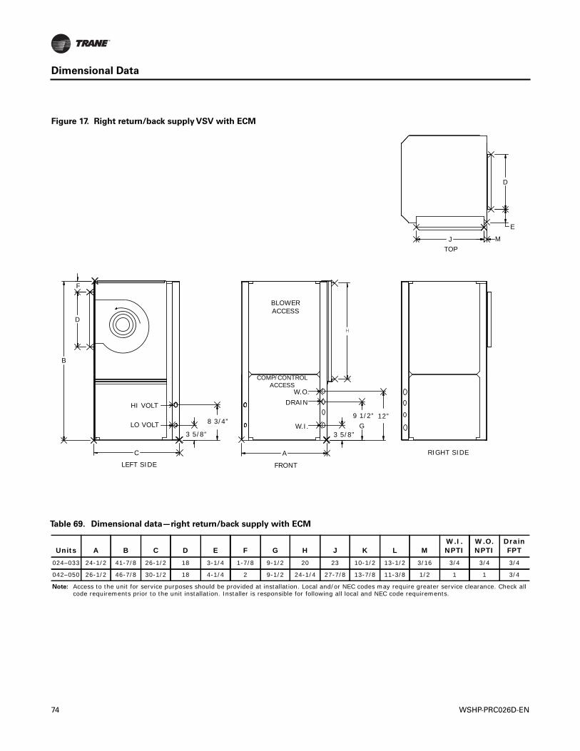
Dimensional Data
Figure 17. Right return/back supply VSV with ECM
H
F
D
B
HI VOLT
LO VOLT
LEFT SIDE
C
BLOWERACCESS
COMP/CONTROLACCESS
W.O.DRAIN
W.I.
A
FRONT
3 5/8”
8 3/4”
3 5/8”
9 1/2”G
12”
RIGHT SIDE
TOPJ M
E
D
Table 69. Dimensional data—right return/back supply with ECM
Units A B C D E F G H J K L MW.I. NPTI
W.O. NPTI
Drain FPT
024–033 24-1/2 41-7/8 26-1/2 18 3-1/4 1-7/8 9-1/2 20 23 10-1/2 13-1/2 3/16 3/4 3/4 3/4
042–050 26-1/2 46-7/8 30-1/2 18 4-1/4 2 9-1/2 24-1/4 27-7/8 13-7/8 11-3/8 1/2 1 1 3/4
Note: Access to the unit for service purposes should be provided at installation. Local and/or NEC codes may require greater service clearance. Check all code requirements prior to the unit installation. Installer is responsible for following all local and NEC code requirements.
74 WSHP-PRC026D-EN
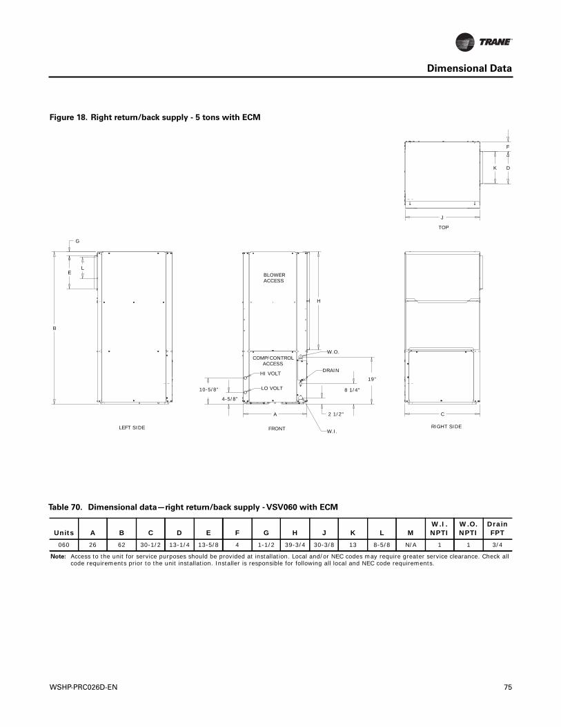
Dimensional Data
Figure 18. Right return/back supply - 5 tons with ECM
H
4-5/8”
10-5/8”
A
B
C2 1/2"
8 1/4"
19”
J
D
F
E
G
K
LBLOWERACCESS
COMP/CONTROLACCESS
TOP
LEFT SIDE FRONT RIGHT SIDE
HI VOLT
LO VOLT
W.O.
W.I.
DRAIN
Table 70. Dimensional data—right return/back supply - VSV060 with ECM
Units A B C D E F G H J K L MW.I. NPTI
W.O. NPTI
Drain FPT
060 26 62 30-1/2 13-1/4 13-5/8 4 1-1/2 39-3/4 30-3/8 13 8-5/8 N/A 1 1 3/4
Note: Access to the unit for service purposes should be provided at installation. Local and/or NEC codes may require greater service clearance. Check all code requirements prior to the unit installation. Installer is responsible for following all local and NEC code requirements.
WSHP-PRC026D-EN 75
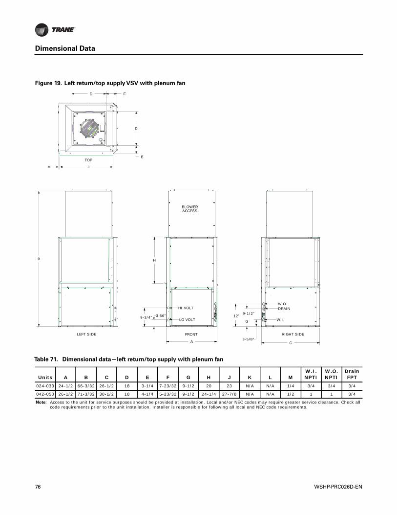
Dimensional Data
Figure 19. Left return/top supply VSV with plenum fan
B H
D
JM
FD
A C3-5/8”
9-1/2”
G12”3.56”9-3/4”
E
BLOWERACCESS
FRONTLEFT SIDE RIGHT SIDE
HI VOLT
LO VOLT
W.O.DRAIN
W.I.
TOP
Table 71. Dimensional data—left return/top supply with plenum fan
Units A B C D E F G H J K L MW.I. NPTI
W.O. NPTI
Drain FPT
024-033 24-1/2 66-3/32 26-1/2 18 3-1/4 7-23/32 9-1/2 20 23 N/A N/A 1/4 3/4 3/4 3/4
042-050 26-1/2 71-3/32 30-1/2 18 4-1/4 5-23/32 9-1/2 24-1/4 27-7/8 N/A N/A 1/2 1 1 3/4
Note: Access to the unit for service purposes should be provided at installation. Local and/or NEC codes may require greater service clearance. Check all code requirements prior to the unit installation. Installer is responsible for following all local and NEC code requirements.
76 WSHP-PRC026D-EN
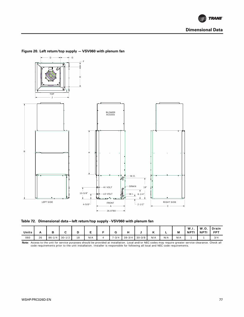
Dimensional Data
Figure 20. Left return/top supply — VSV060 with plenum fan
B
J
D
D G
F
H
10-5/8”
4-5/8” 2-1/2”
8-1/4”
19”
A C
26.0780
BLOWERACCESS
FRONT
TOP
LEFT SIDE RIGHT SIDE
HI VOLT
LO VOLT
W.O.
DRAIN
W.I.
Table 72. Dimensional data—left return/top supply - VSV060 with plenum fan
Units A B C D E F G H J K L MW.I. NPTI
W.O. NPTI
Drain FPT
060 26 86-1/4 30-1/2 18 N/A 4 7-3/4 39-3/4 30-3/8 N/A N/A N/A 1 1 3/4
Note: Access to the unit for service purposes should be provided at installation. Local and/or NEC codes may require greater service clearance. Check all code requirements prior to the unit installation. Installer is responsible for following all local and NEC code requirements.
WSHP-PRC026D-EN 77
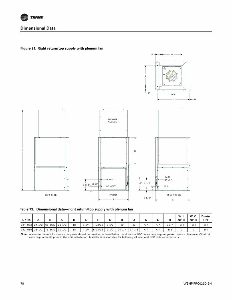
Dimensional Data
Figure 21. Right return/top supply with plenum fan
B H
A C3-5/8”
9-1/2”
G
12”3.56”9-3/4”
MJ
E
D
F D
BLOWERACCESS
FRONTLEFT SIDE RIGHT SIDE
HI VOLT
LO VOLT
W.O.DRAIN
W.I.
TOP
Table 73. Dimensional data—right return/top supply with plenum fan
Units A B C D E F G H J K L MW.I. NPTI
W.O. NPTI
Drain FPT
024–033 24-1/2 66-3/32 26-1/2 18 3-1/4 7-23/32 9-1/2 20 23 N/A N/A 1-3/4 3/4 3/4 3/4
042–050 26-1/2 71-3/32 30-1/2 18 4-1/4 5-23/32 9-1/2 24-1/4 27-7/8 N/A N/A 1/2 1 1 3/4
Note: Access to the unit for service purposes should be provided at installation. Local and/or NEC codes may require greater service clearance. Check all code requirements prior to the unit installation. Installer is responsible for following all local and NEC code requirements.
78 WSHP-PRC026D-EN
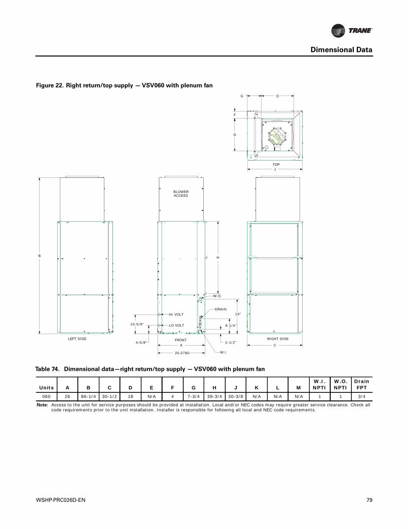
Dimensional Data
Figure 22. Right return/top supply — VSV060 with plenum fan
B H
10-5/8”
4-5/8” 2-1/2”
8-1/4”
19”
A C
26.0780
J
F
D
DG
BLOWERACCESS
FRONT
TOP
LEFT SIDE RIGHT SIDE
HI VOLT
LO VOLT
W.O.
DRAIN
W.I.
Table 74. Dimensional data—right return/top supply — VSV060 with plenum fan
Units A B C D E F G H J K L MW.I. NPTI
W.O. NPTI
Drain FPT
060 26 86-1/4 30-1/2 18 N/A 4 7-3/4 39-3/4 30-3/8 N/A N/A N/A 1 1 3/4
Note: Access to the unit for service purposes should be provided at installation. Local and/or NEC codes may require greater service clearance. Check all code requirements prior to the unit installation. Installer is responsible for following all local and NEC code requirements.
WSHP-PRC026D-EN 79
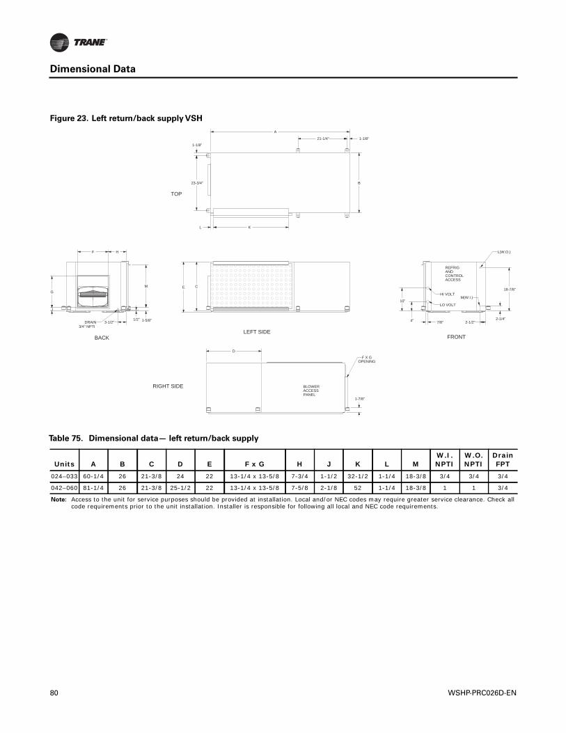
Dimensional Data
Figure 23. Left return/back supply VSH
4” 2-1/4”3-1/2”
F H
M
1-5/8”
CG
J
7/8” 2-1/2”
E
L K
23-3/4”
1-1/8”
1-1/8”21-1/4”
A
B
D
1-7/8”
1/2”
18-7/8”
10”
HI VOLT
LO VOLT
L(W.O.)
FRONTLEFT SIDE
REFRIGANDCONTROLACCESS
M(W.I.)
DRAIN3/4" NPTI
BACK
TOP
F X GOPENING
BLOWERACCESSPANEL
RIGHT SIDE
Table 75. Dimensional data— left return/back supply
Units A B C D E F x G H J K L MW.I. NPTI
W.O. NPTI
Drain FPT
024–033 60-1/4 26 21-3/8 24 22 13-1/4 x 13-5/8 7-3/4 1-1/2 32-1/2 1-1/4 18-3/8 3/4 3/4 3/4
042–060 81-1/4 26 21-3/8 25-1/2 22 13-1/4 x 13-5/8 7-5/8 2-1/8 52 1-1/4 18-3/8 1 1 3/4
Note: Access to the unit for service purposes should be provided at installation. Local and/or NEC codes may require greater service clearance. Check all code requirements prior to the unit installation. Installer is responsible for following all local and NEC code requirements.
80 WSHP-PRC026D-EN
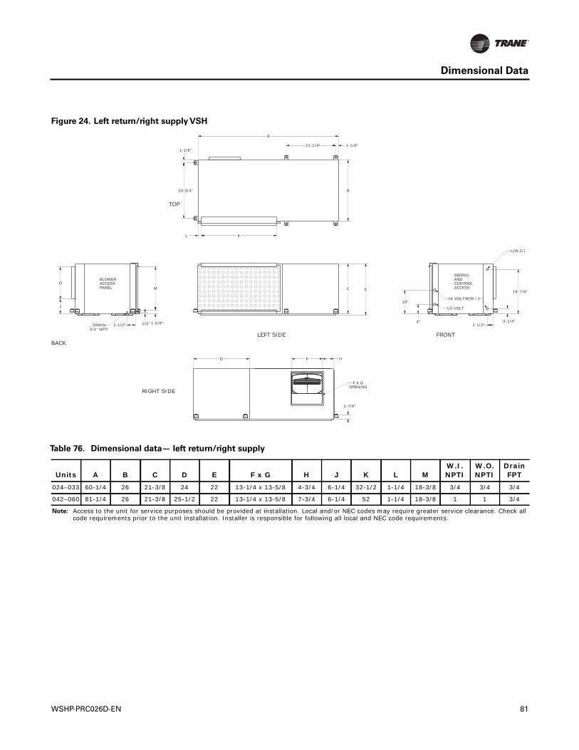
Dimensional Data
Figure 24. Left return/right supply VSH
23-3/4”
1-1/8”
L K
1-1/8”
A
B
C E
D
1-7/8”
2-1/4”4”
F H
G
J
M
1-5/8”3-1/2”
21-1/4”
2-1/2”1/2”
18-7/8”
10”
TOP
HI VOLT
LO VOLT
L(W.O.)
REFRIGANDCONTROLACCESS
M(W.I.)
FRONTLEFT SIDEBACK
DRAIN3/4" NPTI
BLOWERACCESSPANEL
F X GOPENING
RIGHT SIDE
Table 76. Dimensional data— left return/right supply
Units A B C D E F x G H J K L MW.I. NPTI
W.O. NPTI
Drain FPT
024–033 60-1/4 26 21-3/8 24 22 13-1/4 x 13-5/8 4-3/4 6-1/4 32-1/2 1-1/4 18-3/8 3/4 3/4 3/4
042–060 81-1/4 26 21-3/8 25-1/2 22 13-1/4 x 13-5/8 7-3/4 6-1/4 52 1-1/4 18-3/8 1 1 3/4
Note: Access to the unit for service purposes should be provided at installation. Local and/or NEC codes may require greater service clearance. Check all code requirements prior to the unit installation. Installer is responsible for following all local and NEC code requirements.
WSHP-PRC026D-EN 81
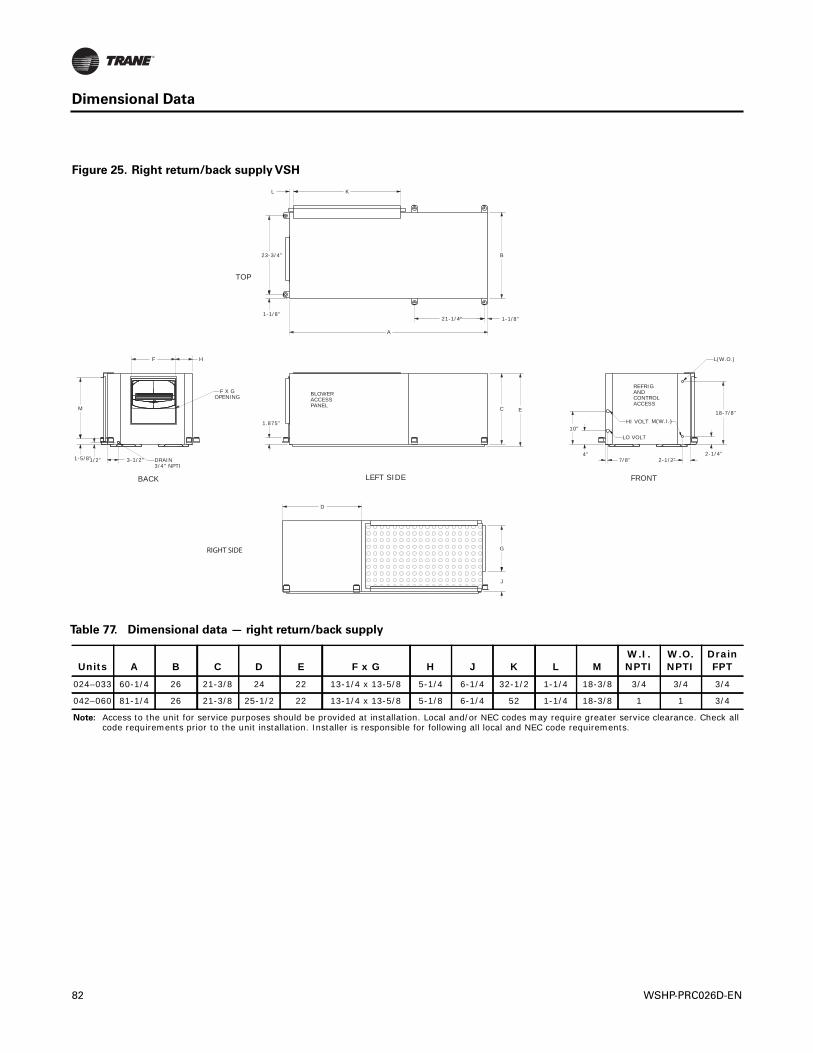
Dimensional Data
Figure 25. Right return/back supply VSH
B
L K
1-1/8”21-1/4”
A
1-1/8”
23-3/4”
2-1/4”4”2-1/2”7/8”
C E
F
M
1-5/8”
H
3-1/2”1/2”
G
J
D
1.875”10”
18-7/8”HI VOLT
LO VOLT
L(W.O.)
REFRIGANDCONTROLACCESS
M(W.I.)
FRONT
BLOWERACCESSPANEL
LEFT SIDE
DRAIN3/4" NPTI
F X GOPENING
BACK
TOP
RIGHT SIDE
Table 77. Dimensional data — right return/back supply
Units A B C D E F x G H J K L MW.I. NPTI
W.O. NPTI
Drain FPT
024–033 60-1/4 26 21-3/8 24 22 13-1/4 x 13-5/8 5-1/4 6-1/4 32-1/2 1-1/4 18-3/8 3/4 3/4 3/4
042–060 81-1/4 26 21-3/8 25-1/2 22 13-1/4 x 13-5/8 5-1/8 6-1/4 52 1-1/4 18-3/8 1 1 3/4
Note: Access to the unit for service purposes should be provided at installation. Local and/or NEC codes may require greater service clearance. Check all code requirements prior to the unit installation. Installer is responsible for following all local and NEC code requirements.
82 WSHP-PRC026D-EN
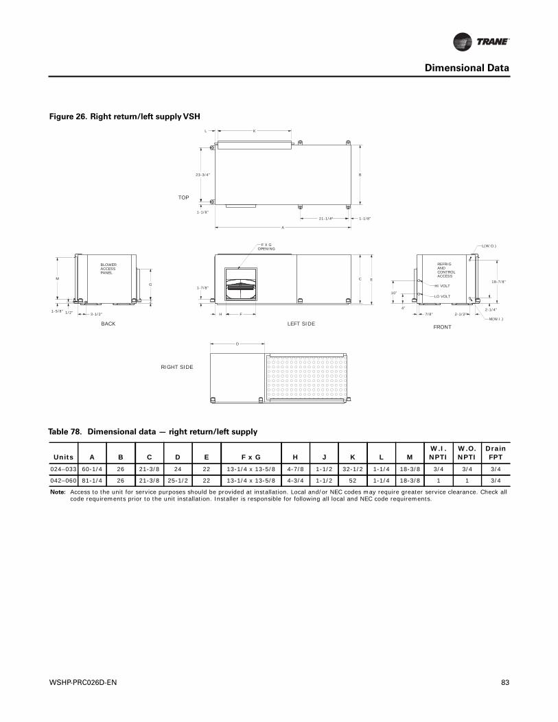
Dimensional Data
Figure 26. Right return/left supply VSH
L K
B
1-1/8”
23-3/4”
21-1/4” 1-1/8”
A
C E
2-1/4”4”
M
1-5/8”
D
1-7/8”
H F
J
G
3-1/2”1/2” 7/8” 2-1/2”
10”
18-7/8”
TOP
REFRIGANDCONTROLACCESS
HI VOLT
LO VOLT
L(W.O.)
M(W.I.)
F X GOPENING
FRONTLEFT SIDEBACK
BLOWERACCESSPANEL
RIGHT SIDE
Table 78. Dimensional data — right return/left supply
Units A B C D E F x G H J K L MW.I. NPTI
W.O. NPTI
Drain FPT
024–033 60-1/4 26 21-3/8 24 22 13-1/4 x 13-5/8 4-7/8 1-1/2 32-1/2 1-1/4 18-3/8 3/4 3/4 3/4
042–060 81-1/4 26 21-3/8 25-1/2 22 13-1/4 x 13-5/8 4-3/4 1-1/2 52 1-1/4 18-3/8 1 1 3/4
Note: Access to the unit for service purposes should be provided at installation. Local and/or NEC codes may require greater service clearance. Check all code requirements prior to the unit installation. Installer is responsible for following all local and NEC code requirements.
WSHP-PRC026D-EN 83
Controls
Tracer™ UC400 Programmable BACnet™ Controller
TheTracer™ UC400 is a programmable, direct digital control (DDC) system designed to control thewater source heat pump unit.The controller provides system-level data used to optimize the overallunit performance. Stand-alone applications as well as full building automation systems via theBACnet™ MS/TP protocol are supported through the controller.
Features and Functions
Complete control of the water source heat pump unit variable speed compressor and supply air fanis provided through theTracer™ UC400.The control strategies are optimized for enhanced energyefficiency and comfort.
The features and functions of theTracer™ UC400 are described in the following sections.
Anti-short CycleTimer
The anti-short cycle timer provides a three minute time delay between compressor stop andcompressor restart.
Compressor Operation
Upon a call for cooling or heating, the compressor will follow a programmed startup sequence withprescribed acceleration rates to safely enable compressor operation. Once ramp up has occurredthe compressor is controlled within minimum and maximum capacity as determined by heatingor cooling demands.When the compressor is no longer needed for cooling or heating, it will followa predefined shutdown sequence to safely turn off.
When switching between heating and cooling modes, the compressor will follow the shutdownsequence prior to de-energizing the compressor. Once the compressor is off the anti-short cycletimer will provide a 3-minute time delay restarting.
Demand Limiting
TheTracer™ UC400 controller supports communicated requests for demand limiting thecompressor and supply fan outputs.When demand limited is enabled, the unit capacity is limitedto a maximum of 50% for all unit modes (cooling and heating). Demand limit requests will notoverride compressor startup and shutdown sequences or unit protection modes (for example, lowentering water temp.)
Enhanced Dehumidification
The variable-speed fan motor (ECM), along with the variable-speed compressor, results inimproved dehumidification performance at part-load conditions compared to a unit with aconstant-speed fan. In addition theTracer™ UC400 controller includes an enhanceddehumidification control mode that can improve dehumidification performance by furtherreducing fan speed. A space humidity value is either communicated from the BAS, or input froma humidity sensor wired into the controller. When the measured space relative humidity enable/disable exceeds the setpoint, the enhanced dehumidification mode is enabled and the fan speedis further reduced to remove moisture. increase dehumidification
Enhanced dehumidification mode does not provide independent (active) control of both spacetemperature and humidity.This mode can only occur when the controller is in the cooling mode,and a high cooling load (warm temperature in the zone) can override the enhanceddehumidification mode.Therefore, in non-arid climates,Trane® recommends the use of adedicated outdoor-air system to dehumidify the outdoor air centrally, rather than relying on theheat pumps to provide sufficient dehumidification (see the “Application Considerations,” sectionof this catalog).
Supply Fan Operation
The UC400 supports continuous fan and fan cycling modes.
84 WSHP-PRC026D-EN
Controls
• Fan Cycling Mode: For active cooling, heating, and operation, the supply fan will becommanded on and will ramp up to the appropriate minimum speed once the unit determinesthere is a request for active compressor output control. When there is no longer an activerequest and all compressor capacity is de-energized, the supply fan will be de-energized onceany supply fan off delays have timed out. In heat mode, the fan will run for 30 seconds beyondcompressor shutdown in both occupied and unoccupied mode.
• Continuous Fan Mode:The unit will energize the supply fan and hold the fan speed output atthe minimum fan speed setting until there is a request for the fan speed to increase.When theunit is in unoccupied mode, however, the supply fan mode operates in cycling mode.
Filter MaintenanceTimer
The controller’s filter status is based on the supply fan’s cumulative run hours.The controllercompares the fan run time against an adjustable fan run hours limit and recommends unitmaintenance as required.
Occupancy Determination
The five operations of theTracer™ UC400 controller include occupied, occupied standby, occupiedbypass, unoccupied and timed override.
• Occupied mode:When the controller is in the OCCUPIED mode, the unit will operate to maintainthe space temperature at the active occupied heating or cooling setpoint.This occupiedoperation is normally used during the daytime hours when the building is at the highestoccupancy level.
• Occupied Standby mode:The occupied standby mode allows the unit to operate at a heatingor cooling setpoints between the occupied and unoccupied setpoints to help maintain the spacewhile decreasing energy consumption. Unit operation in the mode is similar to the occupiedmode except for the different heating and cooling setpoints.The occupied standby operationis used during daytime hours when people are not present in the space (such as lunchtime orrecess).
• Unoccupied mode: When the controller is in the Unoccupied mode, the unit will attempt tomaintain the space temperature at the stored unoccupied heating or cooling setpoint.
• Occupied Bypass mode:This mode is used to transition the unit from the Unoccupied mode tothe Occupied mode for a period of time from 0 to 4 hours.
• Timed Override Operation: If the unit receives a request for timed override mode while the unitis operating in Unoccupied mode, the unit will transition to Occupied Bypass mode for theselected Occupied BypassTime.
Random Start
To prevent all of the units in a building from energizing major loads at the same time, the controllerobserves a random start from 5 to 30 seconds.This timer halts the controller from starting the unituntil the random start time expires.
Reversing Valve Operation
For normal unit operation, the reversing valve output is energized when the unit is in Cooling modeand de-energized in Heating mode. If de-energized, the reversing valve output shall be energizedfor Cooling when the compressor output is energized and the compressor speed has ramped upto the proper startup speed. Once energized, the reversing valve output will remain energized untilthe controller energizes the compressor output for heating and the compressor speed has rampedup to the startup speed for heating or the Unit Mode is set to Off.When a power-failure occurs, thereversing valve output defaults to the heating (de-energized) state.
WSHP-PRC026D-EN 85
Controls
Test Mode
The UC400 shall support two field test modes to allow the user to setup/troubleshoot the system.One test mode is available through theTracer™TU service tool and the other is available througha local input on the UC400.
Water Isolation Valve
For all units, the UC400 shall support a two-position water isolation valve without needing anyspecial configuration; by default, the UC400 will control as though isolation valves are present.
IsolationValve “ON” Control.The isolation valve output will be energized (controlled open) duringcompressor heating, compressor cooling, and when forced open during manual output overridetesting.
When the isolation valve is driven open for compressor operation, the output will be energized 20seconds prior to the compressor and indoor fan (if not already energized) outputs to ensureadequate water flow to the heat exchanger.To reduce excessive cycling of the isolation valve, onceopened, the isolation valve will remain open for a minimum of 10 minutes.
Isolation Valve “OFF” Control.The isolation valve output will be de-energized (controlled closed)when there is no longer a call for compressor operation and the 10 min. minimum on time hasexpired or the manual output override test has driven it closed.
Stand-alone Systems
When units are applied as a stand-alone control system, theTracer™ UC400 provides accuratetemperature control directly through the wall-mounted zone sensor.This system set-up may beutilized in a replacement design where a single unit retrofit is needed or on small jobs where abuilding controller may not be necessary.
Direct Digital Controls for Building Automation Systems
For owners who require a complete building management “open protocol” system, theTracer™UC400 controller may be linked directly to theTrane®Tracer™ SC or other third party BACnet™MS/TP systems.
Building Control Advantages
When water source heat pumps are applied with theTrane®Tracer™ SC, the potential for greaterenergy savings can be achieved.The UC400 controller has the ability to share information with thebuilding automation system via a communications wire.The operation of the system can beoptimized with capabilities such as:
• Centralized system scheduling and shutdown based on occupancy
• Override to allow the system to operate when a zone is occupied after scheduled hours(indicated through the use of a timed override button on the zone sensor)
• Enabling morning warm-up and cool-down sequences, including optimal start
• Centralized alarms to indicate problems, required service or needed maintenance
• Trend logging to help anticipate potential system problems
• Integration with other systems serving the building such as dedicated outdoor-air system,lighting, security, and fire safety
Tracer™TU ServiceTool Support
The UC400 for Variable Speed Water Source Heat Pump Units will be supported by theTrane®Tracer™TU ServiceTool and can be used to change default setpoints as well as view activediagnostics/alarms.The UC400 will also support a version of ServiceTest Mode that will beavailable through theTracer™TU communication link.
86 WSHP-PRC026D-EN
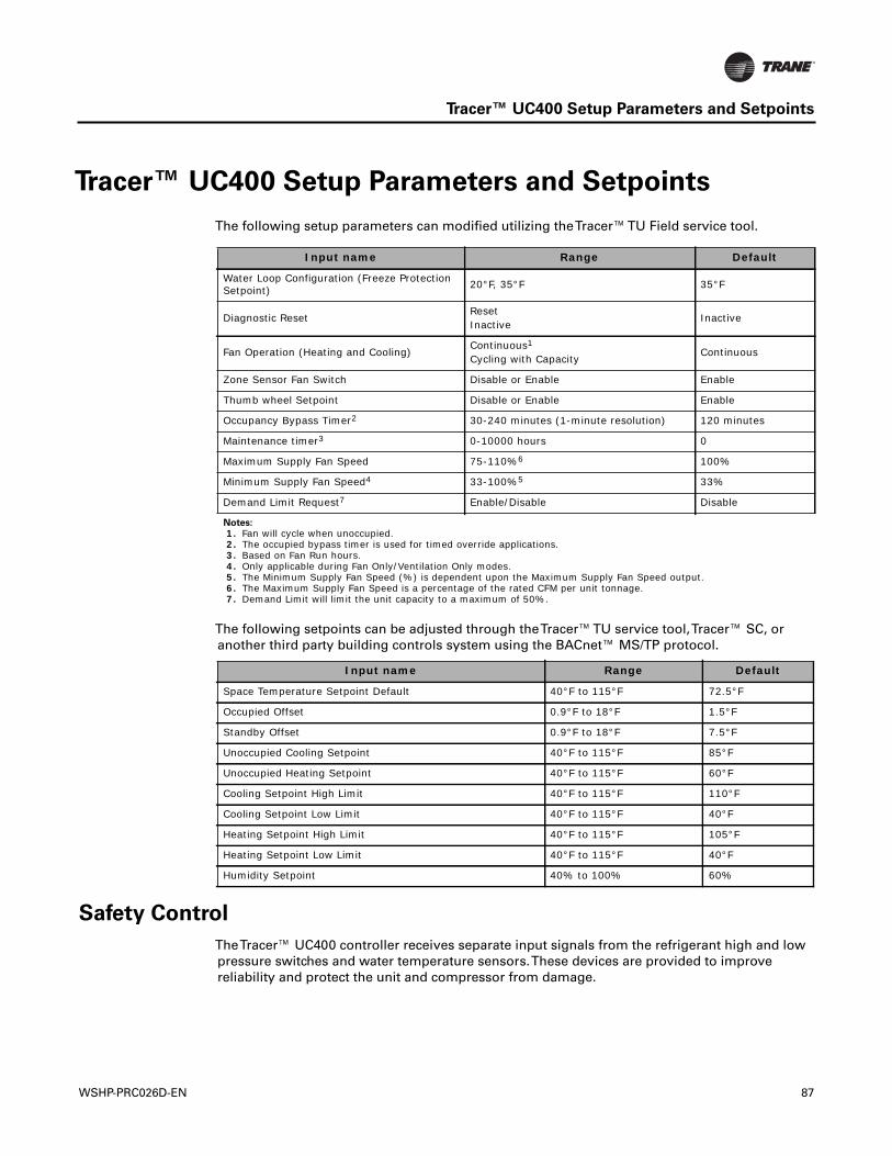
Tracer™ UC400 Setup Parameters and Setpoints
Tracer™ UC400 Setup Parameters and Setpoints
The following setup parameters can modified utilizing theTracer™TU Field service tool.
The following setpoints can be adjusted through theTracer™TU service tool,Tracer™ SC, oranother third party building controls system using the BACnet™ MS/TP protocol.
Safety Control
TheTracer™ UC400 controller receives separate input signals from the refrigerant high and lowpressure switches and water temperature sensors.These devices are provided to improvereliability and protect the unit and compressor from damage.
Input name Range Default
Water Loop Configuration (Freeze Protection Setpoint) 20°F, 35°F 35°F
Diagnostic ResetResetInactive
Inactive
Fan Operation (Heating and Cooling) Continuous1
Cycling with CapacityContinuous
Zone Sensor Fan Switch Disable or Enable Enable
Thumb wheel Setpoint Disable or Enable Enable
Occupancy Bypass Timer2 30-240 minutes (1-minute resolution) 120 minutes
Maintenance timer3 0-10000 hours 0
Maximum Supply Fan Speed 75-110%6 100%
Minimum Supply Fan Speed4 33-100%5 33%
Demand Limit Request7 Enable/Disable Disable
Notes:
1. Fan will cycle when unoccupied. 2. The occupied bypass timer is used for timed override applications. 3. Based on Fan Run hours. 4. Only applicable during Fan Only/Ventilation Only modes. 5. The Minimum Supply Fan Speed (%) is dependent upon the Maximum Supply Fan Speed output. 6. The Maximum Supply Fan Speed is a percentage of the rated CFM per unit tonnage. 7. Demand Limit will limit the unit capacity to a maximum of 50%.
Input name Range Default
Space Temperature Setpoint Default 40°F to 115°F 72.5°F
Occupied Offset 0.9°F to 18°F 1.5°F
Standby Offset 0.9°F to 18°F 7.5°F
Unoccupied Cooling Setpoint 40°F to 115°F 85°F
Unoccupied Heating Setpoint 40°F to 115°F 60°F
Cooling Setpoint High Limit 40°F to 115°F 110°F
Cooling Setpoint Low Limit 40°F to 115°F 40°F
Heating Setpoint High Limit 40°F to 115°F 105°F
Heating Setpoint Low Limit 40°F to 115°F 40°F
Humidity Setpoint 40% to 100% 60%
WSHP-PRC026D-EN 87
Tracer™ UC400 Setup Parameters and Setpoints
Low Refrigerant Flow Rate Control
Low Entering WaterTemperature
During Low Entering WaterTemperature conditions, the minimum compressor speed will bemodified based on the active operating mode and the entering water temperature.
ExtendedTime @ Compressor Low Speed (Oil Recovery Mode)
If the compressor operates for 90 continuous minutes at the minimum speed the compressor speedshall ramp to 50% for 3 minutes and then will be released back to normal operation.
Compressor Protection Control
An input on the UC400 is dedicated to monitoring the status of the high pressure, low pressure andtemperature and discharge line temperature devices for compressor protection control.
Condensate Overflow
All units have a UL508 condensate overflow installed as standard. When condensate reaches thetrip point, a condensate overflow signal generates a diagnostic which disables the fan, unit watervalve (if present), and compressor.
Entering WaterTemperature Sampling
The UC400 shall sample the entering water temperature to determine proper control action for theunit.The entering water temperature will be measured when there is a new request for compressoroperation, the isolation valve is not open, and it has been greater than one hour since the lastsampling occurred.
Freeze Protection
The unit is protected from low temperature water via a leaving water temperature sensor installedin the unit.
88 WSHP-PRC026D-EN
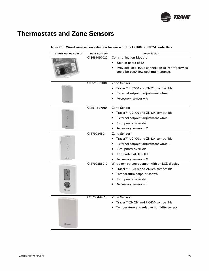
Thermostats and Zone Sensors
Table 79. Wired zone sensor selection for use with the UC400 or ZN524 controllers
Thermostat/sensor Part number DescriptionX13651467020 Communication Module
• Sold in packs of 12
• Provides local RJ22 connection toTrane® servicetools for easy, low cost maintenance.
X13511529010 Zone Sensor
• Tracer™ UC400 and ZN524 compatible
• External setpoint adjustment wheel
• Accessory sensor = A
X13511527010 Zone Sensor
• Tracer™ UC400 and ZN524 compatible
• External setpoint adjustment wheel
• Occupancy override
• Accessory sensor = C
X1379084501 Zone Sensor
• Tracer™ UC400 and ZN524 compatible
• External setpoint adjustment wheel.
• Occupancy override
• Fan switch AUTO-OFF
• Accessory sensor = GX13790886010 Wired temperature sensor with an LCD display
• Tracer™ UC400 and ZN524 compatible
• Temperature setpoint control
• Occupancy override
• Accessory sensor = J
X1379044401 Zone Sensor
• Tracer™ ZN524 and UC400 compatible
• Temperature and relative humidity sensor
WSHP-PRC026D-EN 89
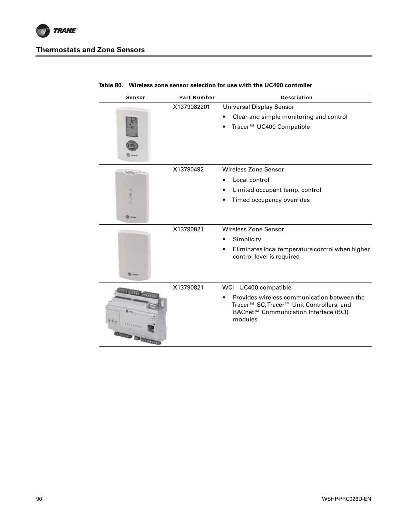
Thermostats and Zone Sensors
Table 80. Wireless zone sensor selection for use with the UC400 controller
Sensor Part Number Description
X1379082201 Universal Display Sensor
• Clear and simple monitoring and control
• Tracer™ UC400 Compatible
X13790492 Wireless Zone Sensor
• Local control
• Limited occupant temp. control
• Timed occupancy overrides
X13790821 Wireless Zone Sensor
• Simplicity
• Eliminates local temperature control when highercontrol level is required
X13790821 WCI - UC400 compatible
• Provides wireless communication between theTracer™ SC,Tracer™ Unit Controllers, andBACnet™ Communication Interface (BCI)modules
90 WSHP-PRC026D-EN
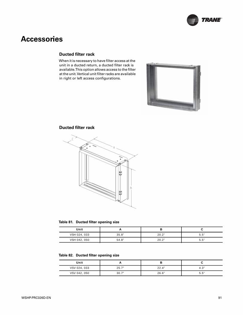
Accessories
Ducted filter rack
When it is necessary to have filter access at theunit in a ducted return, a ducted filter rack isavailable.This option allows access to the filterat the unit.Vertical unit filter racks are availablein right or left access configurations.
Ducted filter rack
Table 81. Ducted filter opening size
Unit A B C
VSH 024, 033 35.8” 20.2” 5.5”
VSH 042, 050 54.8” 20.2” 5.5”
Table 82. Ducted filter opening size
Unit A B C
VSV 024, 033 25.7” 22.4” 4.3”
VSV 042, 050 30.7” 26.6” 5.5”
WSHP-PRC026D-EN 91
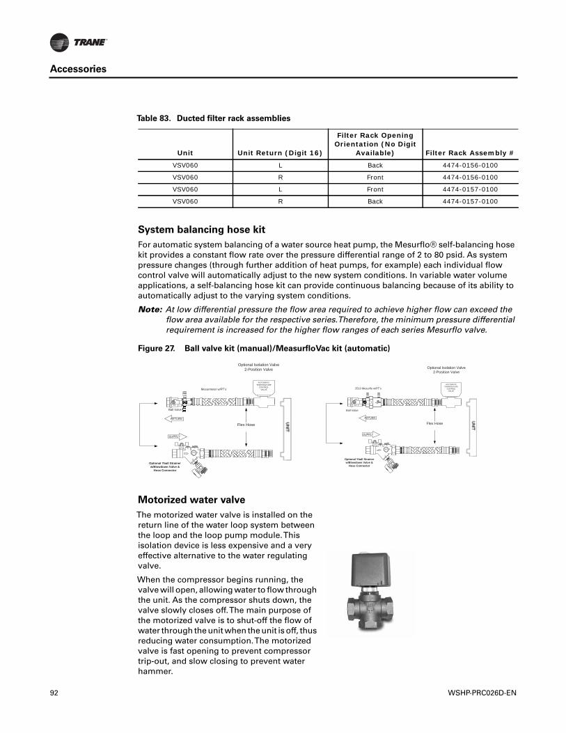
Accessories
System balancing hose kit
For automatic system balancing of a water source heat pump, the Mesurflo® self-balancing hosekit provides a constant flow rate over the pressure differential range of 2 to 80 psid. As systempressure changes (through further addition of heat pumps, for example) each individual flowcontrol valve will automatically adjust to the new system conditions. In variable water volumeapplications, a self-balancing hose kit can provide continuous balancing because of its ability toautomatically adjust to the varying system conditions.
Note: At low differential pressure the flow area required to achieve higher flow can exceed theflow area available for the respective series.Therefore, the minimum pressure differentialrequirement is increased for the higher flow ranges of each series Mesurflo valve.
Table 83. Ducted filter rack assemblies
Unit Unit Return (Digit 16)
Filter Rack Opening Orientation (No Digit
Available) Filter Rack Assembly #
VSV060 L Back 4474-0156-0100
VSV060 R Front 4474-0156-0100
VSV060 L Front 4474-0157-0100
VSV060 R Back 4474-0157-0100
Figure 27. Ball valve kit (manual)/MeasurfloVac kit (automatic)
Motorized water valve
The motorized water valve is installed on thereturn line of the water loop system betweenthe loop and the loop pump module.Thisisolation device is less expensive and a veryeffective alternative to the water regulatingvalve.
When the compressor begins running, thevalve will open, allowing water to flow throughthe unit. As the compressor shuts down, thevalve slowly closes off.The main purpose ofthe motorized valve is to shut-off the flow ofwater through the unit when the unit is off, thusreducing water consumption.The motorizedvalve is fast opening to prevent compressortrip-out, and slow closing to prevent waterhammer.
Flex Hose
Mesurmeter w/PT’s
Optional Yball Strainer w/Blowdown Valve &
Hose Connector
PTFLOW
Ball Valve
Optional Isolation Valve2-Position Valve
AUTOMATICTEMPERATURE
CONTROL VALVE
Flex Hose
Optional Yball Strainer w/Blowdown Valve &
Hose Connector
PTFLOW
Ball Valve
Optional Isolation Valve2-Position Valve
2510 Mesurflo w/PT’sAUTOMATIC
TEMPERATURECONTROL
VALVE
92 WSHP-PRC026D-EN
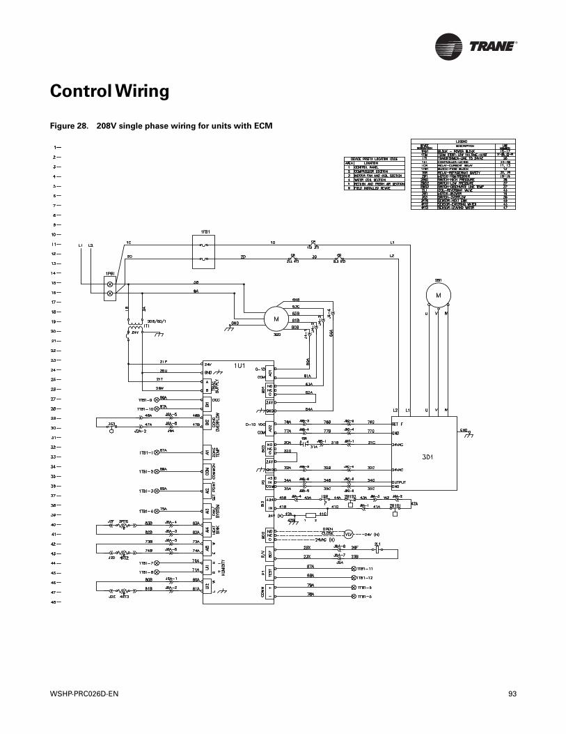
Control Wiring
Figure 28. 208V single phase wiring for units with ECM
WSHP-PRC026D-EN 93
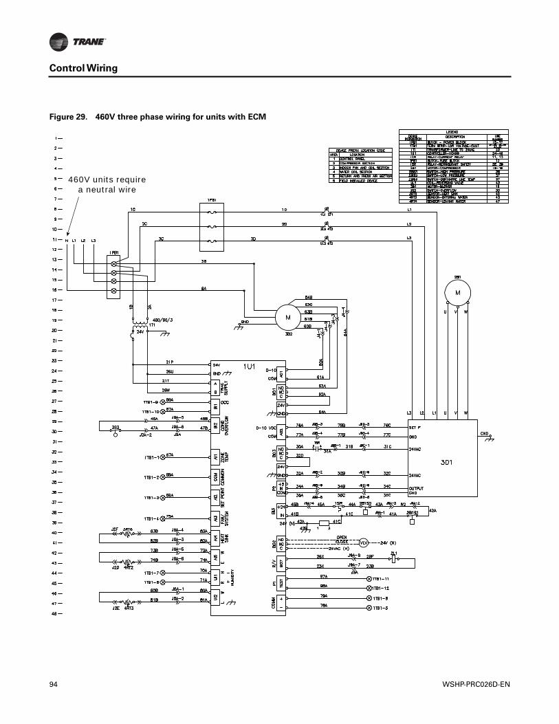
Control Wiring
Figure 29. 460V three phase wiring for units with ECM
460V units require a neutral wire
94 WSHP-PRC026D-EN
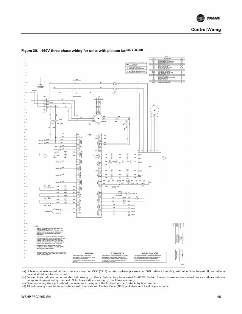
Control Wiring
Figure 30. 460V three phase wiring for units with plenum fan(a),(b),(c),(d)
(a) Unless otherwise noted, all switches are shown at 25°C (77°F), at atmospheric pressure, at 50% relative humidity, with all utilities turned off, and after anormal shutdown has occurred.
(b) Dashed lines indicate recommended field wiring by others. Field writing to be rated for 600V. Dashed line enclosure and/or dashed device outlines indicatecomponents provided by the field. Solid lines indicate wiring by the Trane company.
(c) Numbers along the right side of the schematic designate the location of the contacts by line number.(d) All field wiring must be in accordance with the National Electric Code (NEC) and state and local requirements.
WSHP-PRC026D-EN 95
Mechanical Specifications
General
Trane water source heat pump model Axiom VS shall be furnished and installed.
Equipment shall be factory assembled, piped, internally wired, fully charged with R-410Arefrigerant and oil and test operated at the factory.The unit shall have an operating range is 45 to120°F entering water temperature in cooling and 25°F to 85°F entering water temperature inheating.
Product shall be designed, rated and certified in accordance with ETL, CETL, and ISO-AHRI13256-1. Unit shall meet the efficiency standards of the ASHRAE 90.1 standard.
Air-to-Refrigerant Coil
The air-to-refrigerant coil shall consist of copper tubes mechanically bonded into evenly spacedaluminum fins.All coils shall be leak tested to 450 psig and pressure tested to 650 psig at the factoryto ensure the pressure integrity.The tubes are completely evacuated of air and correctly chargedwith proper volume of refrigerant prior to shipment.The refrigerant coil distributor assembly shallbe of orifice style with round copper distributor tubes.The tubes are sized consistently with thecapacity of the coil. Suction headers are fabricated from rounded copper pipe.
Cabinet/Casing
The unit frame shall be constructed of heavy-gage, galvanized steel.The panels are insulated with1/2-inch thick foil faced glass fiber insulation to provide thermal and acoustical insulation.Theinsulation is UL listed and meets NFPA-90A and UL 181 standard.
Access for inspection and cleaning of the unit drain pan, coils and fan section is provided.The unitshall be installed for proper access. Procedures for proper access, inspection and cleaning of theunit are included in the installation, operation and maintenance manual.
Compressors
Units shall have a high efficiency rotary (24 and 33 Mbtuh) or scroll (42, 50 and 60 Mbtuh) variablespeed type compressor. An inverter board for speed control of the compressor shall also beprovided as standard.
The compressor shall be dually isolated. External vibration isolation is provided by rubbermounting devices located underneath the mounting base of the compressor. A second isolation ofthe refrigerant assembly is supported under the compressor mounting base.
Internal thermal overload protection shall be provided. Protection against excessive dischargepressure shall be provided by means of a high pressure switch. A loss of charge shall be providedby a low pressure safety.
Controls
The unit shall utilize a factory furnished, programmed and mounted direct digital controller.TheUC400 is a 23 I/O point BACnet™ MS/TP controller capable of a standalone application or as appliedto a full building automation system.
The controller provides anti-short cycle compressor protection, random start delay, heating/cooling status, occupied/unoccupied mode, high and low pressure safety control, filtermaintenance timer, compressor status (high/low pressure), drive status (operating or failed), freezeprotection and condensate overflow.
Drain Pan
The drain pan shall be constructed of corrosion resistant HDPE (high density polyethylene) orstainless steel material.The bottom of the drain pan shall be sloped on two planes to pitchcondensate to the drain connection.The drain pan shall comply with ASHRAE 62 for IAQconformity.A UL508 float switch shall be factory installed on all units as standard to protect againstthe overflow of condensate from the drain pan.The drain must be externally trapped.
96 WSHP-PRC026D-EN
Mechanical Specifications
Electrical
The unit control box shall contain all necessary devices to allow heating and cooling operation tooccur from a remote mounted zone sensor.These devices shall be as follows:
• 75 VA transformer
• A low-voltage terminal strip located inside the control panel behind the service access panel—may be used for low-voltage (zone sensor) connections
• An additional neutral wire for installation, required by units with 460V power
Enhanced Dehumidification Control
A humidity sensor shall be available as a field installed option for dehumidification operation. Incooling mode, when the space humidity level exceeds the setpoint, the enhanced dehumidificationmode will reduce the fan speed to increase dehumidification.
Fan and Motor Assembly
The fan is a forward-curved style wheel constructed of corrosion resistant galvanized material.Thefan is placed in a draw-through configuration and is arranged for top or back supply air.Thisassembly shall attach the wheel and motor to the fan housing providing single side service access.
The fan motor is an ECM programmable type motor.The motor is programmed at the factory forvariable air flow. Minimum and maximum airflow settings are configurable.
The motor has permanently lubricated and sealed bearings and is protected by an internal thermaloverload.The motor contains a quick disconnect plug for ease of maintenance. Removal of themotor and fan wheel shall be made with the assistance of a factory provided orifice ring assembly.
Filters
Units come standard with a flat filter rack for non-ducted return air applications. A one-inchdisposable filter shall be provided with the unit as standard. Optional two-inch disposable, two-inchMERV 8 or two-inch MERV 13 are available as an option.
Filter Access—Ducted Return
An optional ducted filter rack shall be provided as a field installed accessory for applicationsrequiring filter access at the unit in a ducted return.The vertical unit filter rack has side access.
Freeze Protection
Freeze protection (35°F or 20°F) shall be provided by use of a thermistor on the leaving watertemperature side of the unit.
Refrigerant Circuit
Within the refrigerant circuit, access ports shall be factory supplied on the high and low pressuresides for easy refrigerant pressure or temperature testing. A filter drier shall be provided andfactory-installed within the refrigeration circuit. Internal thermal overload protection is alsoprovided. Protection against excessive discharge pressure is provided by means of a high pressureswitch. A loss of charge is provided by a low pressure safety.
The refrigerant tubing shall be of 99% pure copper.This system is clean and free from contaminantsand conditions such as drilling fragments, dirt, and oil. All refrigerant and water lines are insulatedwith an elastomeric insulation that has a 3/8” thick wall wherever air is introduced to the assembly.
Refrigerant Metering
The equipment is provided with a bi-directional thermal expansion valve (TXV).The device allowsthe operation of the equipment in the range of 25°F to 120°F entering fluid temperature and 55°Fto 90°F entering air temperatures for either water loop or ground loop (geothermal) applications.
WSHP-PRC026D-EN 97

Mechanical Specifications
Reversing Valve
Units shall come standard with a reversing valve for heating and cooling operation.The reversingvalve is a pilot operating sliding piston type with replaceable encapsulated magnetic coil.Thisvalve shall be energized in cooling.
Sound Attenuation
Sound attenuation shall be a standard feature in the product design.The sound reduction packageshall include, vibration isolation to the compressor and water-to-refrigerant coil, unit basestiffeners, insulated heave gauge metal enclosure, and a second stage of vibration isolation to thecompressor and water-to-refrigerant coil base pan.
Water-to-Refrigerant Heat Exchanger
The water-to-refrigerant heat exchanger is a high quality co-axial coil for maximum heat transfer.The copper coil is deeply fluted to enhance heat transfer and minimize fouling and scaling.The coilhas a working pressure of 400 on the water side and 660 psig on the refrigerant side. Cupro-nickelmay be provided as an option.
Zone Sensors
Zone sensors are available to interface with the UC400 controller and control the unit to the desiredstage of cooling or heating.These sensors are field installed in the zone.
98 WSHP-PRC026D-EN

Trane optimizes the performance of homes and buildings around the world. A business of Ingersoll Rand, the leader increating and sustaining safe, comfortable and energy efficient environments,Trane offers a broad portfolio of advancedcontrols and HVAC systems, comprehensive building services, and parts. For more information, visit www.Trane.com.
Trane has a policy of continuous product and product data improvement and reserves the right to change design and specifications without notice.
We are committed to using environmentally
conscious print practices that reduce waste.
© 2014Trane All rights reserved
WSHP-PRC026D-EN 05 Dec 2014
Supersedes WSHP-PRC026-EN (03 Feb 2013)