Water from rock outcrops
63
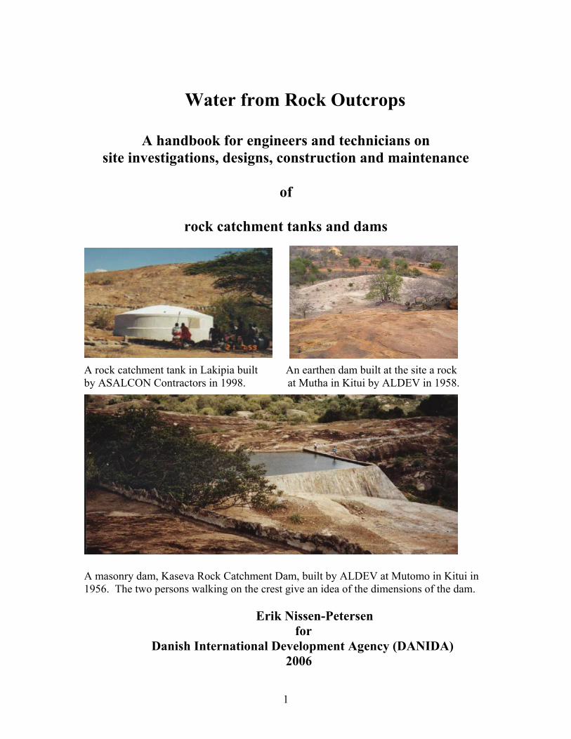
1 Water from Rock Outcrops A handbook for engineers and technicians on site investigations, designs, construction and maintenance of rock catchment tanks and dams A rock catchment tank in Lakipia built An earthen dam built at the site a rock by ASALCON Contractors in 1998. at Mutha in Kitui by ALDEV in 1958. A masonry dam, Kaseva Rock Catchment Dam, built by ALDEV at Mutomo in Kitui in 1956. The two persons walking on the crest give an idea of the dimensions of the dam. Erik Nissen-Petersen for Danish International Development Agency (DANIDA) 2006
-
Upload
stephen-musimba -
Category
Technology
-
view
993 -
download
2
Transcript of Water from rock outcrops
1
Water from Rock Outcrops
A handbook for engineers and technicians on
site investigations, designs, construction and maintenance
of
rock catchment tanks and dams
A rock catchment tank in Lakipia built An earthen dam built at the site a rock by ASALCON Contractors in 1998. at Mutha in Kitui by ALDEV in 1958.
A masonry dam, Kaseva Rock Catchment Dam, built by ALDEV at Mutomo in Kitui in 1956. The two persons walking on the crest give an idea of the dimensions of the dam.
Erik Nissen-Petersen for Danish International Development Agency (DANIDA)
2006

2
Technical handbooks in this series :
Titles Contents 1 Water for rural communities Lessons learnt from Kitui pilot projects 2 Water supply by rural builders Procedures for being rural contractors 3 Water surveys and designs Survey, design and cost of water projects 4 Water from rock outcrops Rock catchment tanks, masonry and earth dams 5 Water from dry riverbeds River-intakes, subsurface dams and sand dams 6 Water from roads Rainwater harvesting from roads 7 Water from small earth dams Ponds and small earth dams built manually 8 Water from roofs Various types of roof catchments for domestic use These handbooks can be obtained free of charge by either collecting them from the office of ASAL Consultants Ltd., or by bank transferring the cost of sending the manuals by courier. For further details, please contact by email : [email protected] with copy to [email protected]
Publisher ASAL Consultants Ltd. for the Danish International Development Agency (DANIDA)
Text Erik Nissen-Petersen
Photos and sketches Erik Nissen-Petersen
Proofs Amin Verjee
Printer English Press, P.O. Box 30127, Nairobi, Kenya
Website creation Ludovic Linas (Fredlink Ltd.) P.O. Box 85976, Mombasa, Kenya [email protected] Mobile : 0735 663 610
Distribution ASAL Consultants Ltd. P.O. Box 739, Sarit 00606, Nairobi, Kenya [email protected] [email protected] Fax/Tel : 254 (0) 202 710 296 Mobile nos : 0733 619 066 or 0722 599 165 Website : www.waterforaridland.com
Copyright The copyright of this handbook is the property of the Royal Danish Embassy in Kenya. Downloading from the internet and photocopying of handbooks is free provided the source is acknowledged.

3
Contents Page Acknowledgement ………………………………………………… v Acronyms ………………………………………………………….. vi Foreword …………………………………………………………… vii Chapter 1. Introduction ……………………………………….. 1 1.1 How can rocks supply water ? ……………………………… 1 1.2 The capacity of rock to supply water ………………………. 2 1.3 Benefits of rock catchments ………………………………... 2 1.4 Disadvantages of rock catchments …………………………. 3 1.5 History of rock catchments ………………………………… 3 1.6 Lessons learnt ………………………………………………. 5 Chapter 2. Community Participation …………………………. 6 2.1 Social and cultural considerations …………………………... 6 2.2 Health issues ………………………………………………… 7 2.3 Cost benefits …………………………………………………. 8 2.4 Environmental feasibility and impact ……………………….. 9 2.5 Administrative guidelines …………………………………… 10 2.6 Writing a proposal for a rock catchment project ……………. 11 2.7 Methods of raising funds locally ……………………………. 12 Chapter 3. Rock suitable for rock catchments ……………….. 13 3.1 Suitable types of rocks ………………………………………. 13 3.2 How were rocks created ? ........................................................ 14 3.3 Components of rock catchments …………………………….. 15 3.4 Where to find suitable sites for rock catchments ……………. 16 Chapter 4. Relation between catchment areas and reservoirs .. 17 4.1 Seasonal rainfall ……………………………………………… 17 4.2 Evaporation loss from rains falling on rocks ………………… 17 4.3 Size and slope of catchment areas …………………………… 17 4.4 Example of run-off water from a catchment of rocks ……….. 20 4.5 Tools and equipment for survey and design …………………. 21 Chapter 5. How to estimate the volume of dam reservoirs ……. 22 5.1 The simplest method ………………………………………….. 22 5.2 A more precise but complicated method ……………………… 22 5.3 Tools and equipment for survey and design ………………….. 24

4
Chapter 6. Water tanks at rocks .……………………………….. 25 6.1 Site criteria for water tanks …………………………………… 25 6.2 How to estimate the volume of a cylindrical tank ……………. 25 6.3 Design of a 50 cubic meter rock catchment tank …………….. 26 6.4 Bill of quantity and cost of a water tank with dome & gutters .. 26 6.5 Construction of a water tank built of rubble stone blocks ……. 27 6.6 Construction of stone gutters …………………………………. 29 Chapter 7. Masonry dams on rocks …………………………….. 30 7.1 The ALDEV design …………………………………………… 30 7.2 Other types of rock catchment dams ………………………….. 31 7.3 Site criteria ……………………………………………………. 32 7.4 Roofs on rock catchment dams ……………………………….. 35 7.5 Masonry dams built in stages …………………………………. 36 7.6 Setting out dam walls …………………………………………. 37 7.7 Calculating the cost of constructing dam walls ………………. 39 7.8 Bill of quantity and cost of dam walls ………………………… 41 7.9 Construction of dam walls built of rubble stone masonry ……. 42 7.10 Construction of draw-off piping ………………………………. 46 7.11 Roofs of ferro-cement over dam reservoirs …………………… 47 7.12 Construction of a roof made of ferro-cement …………………. 48 Chapter 8. Earth dams at rock outcrops ………………………… 49 8.1 Design criteria …………………………………………………. 8.2 Advantages of a hemi-spherical water reservoir ………………. 8.3 Soil sampling ………………………………………………….. 8.4 Bill of quantity and cost ……………………………………….. 8.5 Construction procedure ………………………………………... References ……………………………………………………………..

5
Acknowledgement I am very grateful to Ms Birgit Madsen of the Royal Danish Embassy in Kenya for her interest and full support to publish this handbook on harvesting rainwater from rock outcrops. Many thanks are also due to Danida and the Ministry of Agriculture in Kenya for having given me the opportunity to design and construct more than 100 rock catchments of 9 different types in Kitui from 1982 to 1990. A thousand thanks are also given to the many local and enthusiastic selfhelp groups, especially, in Mutomo Division of Kitui District. They identified suitable rocks and cleared assess roads to them, while also removing all soil and vegetation on the rock outcrops to facilitate survey and design. People carried voluntarily and without any payment thousands of tonnes of sand, stones, water and cement on their back to the construction sites often situated hundred of metres up on inselsbergs with steep rock sides during those 8 years. All this work had only one purpose, namely to create water reservoirs on rock outcrops and inselbergs from where the harvested rainwater was piped down by gravity to tapstands at the ground level. Even today, almost 25 years later, all the 400 or so rock catchments in Kitui District are still supplying water to tens of thousands of people. Although rains are getting more erratic and scarce, rock catchments are still able to supply large volume of water from little rain showers due to their large and impermeable rocks surfaces. Erik Nissen-Petersen Managing Director ASAL Consultants Ltd. P.O. Box 739, Sarit 00606, Nairobi, Kenya [email protected] and [email protected]

6
Acronyms ALDEV = African Land Development Board in 1950s ASAL = Arid and Semi-Arid Land ASALCON = ASAL Consultants Ltd. BQ = Bill of Quantities Cu.m. = Cubic metres Danida = Danish International Development Agency Km = Kilometres Ksh = Kenyan Shillings Mm = Millimetres Sida = Swedish International Development Agency WSB = Water Services Boards WSTF = Water Services Trust Fund
Foreword In Arid and Semi Arid Lands (ASAL) where water is scarce and poorly distributed, water resource availability and its appropriate development and use are key determinants in development. Therefore, community owned development of surface water through rainwater harvesting is emphasized in the Draft National Policy for Sustainable Development of the Arid and Semi Arid Lands of Kenya. Danida is through the Kenya Water and Sanitation Programme (KWSP) providing support to water resources management based on the objectives of the National Water Resources Management Strategy. A main focus of the strategy is to assist the new institutions, in particular the Water Resources Management Authority (WRMA) to establish integrated water resources management at national, regional and local levels. ASAL Consultants Ltd. has a long history and extensive experience with development of water supply facilities in Arid and Semi Arid Lands and in particular with construction of more than 100 rock catchment dams during the last 25 years. All the rock catchments are still functioning. The skills, knowledge and lessons learnt of ASAL Consultants Ltd. in partnership with engineers of the Government of Kenya provides valuable information on methodology and technical designs, which are useful to share with others. Appropriate calculations and measures to get the right dimension of rock catchments and estimates of dam reservoirs and site criteria, just to mention a few of the technical engineering constructions, are essential knowledge and skills to acquire in order to construct sustainable structures. The Royal Danish Embassy has worked closely with ASAL Consultants Ltd. during implementation of 6 pilot projects since 2003 and is convinced that this handbook will be a useful contribution in further development of sustainable surface water facilities in Arid and Semi Arid Lands. Birgit Madsen Councellor (Dev.)
Royal Danish Embassy Nairobi
7
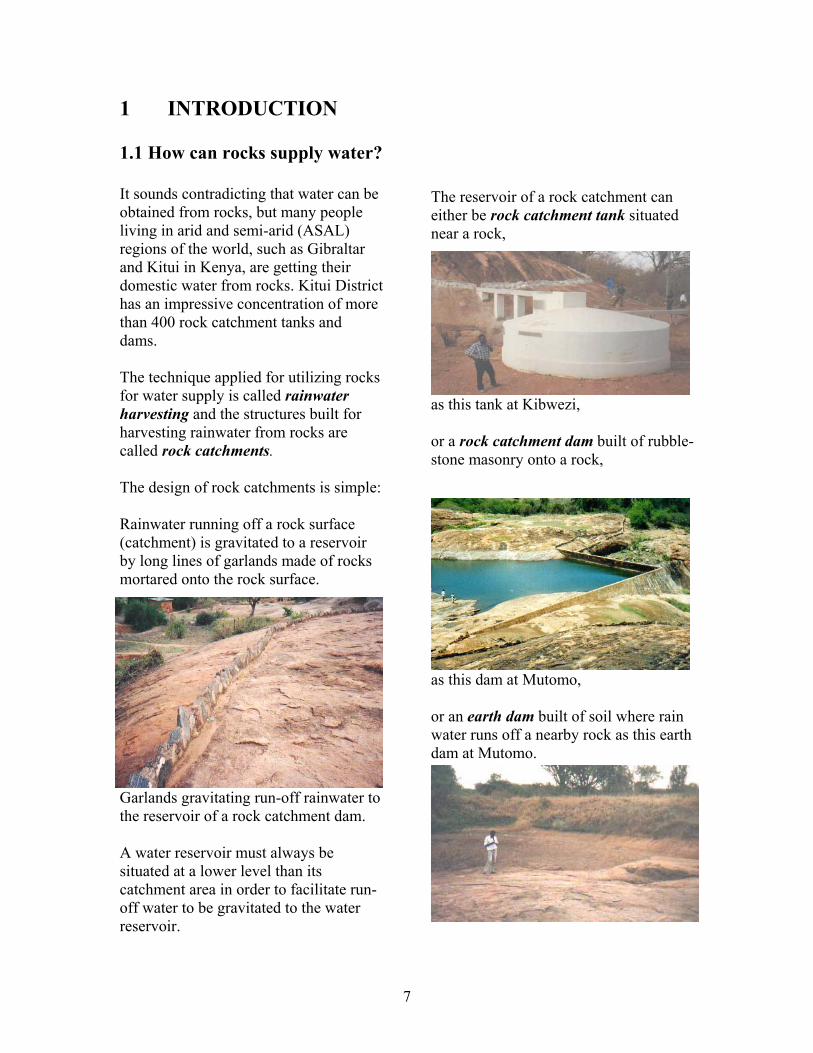
1 INTRODUCTION 1.1 How can rocks supply water? It sounds contradicting that water can be obtained from rocks, but many people living in arid and semi-arid (ASAL) regions of the world, such as Gibraltar and Kitui in Kenya, are getting their domestic water from rocks. Kitui District has an impressive concentration of more than 400 rock catchment tanks and dams. The technique applied for utilizing rocks for water supply is called rainwater harvesting and the structures built for harvesting rainwater from rocks are called rock catchments. The design of rock catchments is simple: Rainwater running off a rock surface (catchment) is gravitated to a reservoir by long lines of garlands made of rocks mortared onto the rock surface.
Garlands gravitating run-off rainwater to the reservoir of a rock catchment dam. A water reservoir must always be situated at a lower level than its catchment area in order to facilitate run-off water to be gravitated to the water reservoir.
The reservoir of a rock catchment can either be rock catchment tank situated near a rock,
as this tank at Kibwezi, or a rock catchment dam built of rubble- stone masonry onto a rock,
as this dam at Mutomo, or an earth dam built of soil where rain water runs off a nearby rock as this earth dam at Mutomo.

8
1.2 The capacity of rocks to supply water The capacity of rocks to supply water is significant, because a rock surface of 1 hectare (10,000 square metres = 2.47 acres) can provide 1,000 cubic metres (1 million litres) from every 100 millimetre of rain (Gould and Nissen-Petersen, 1999). For example: If an ASAL area has two annual rainy seasons and each season has a rainfall of 300 mm, then 1 acre (4,049 square metres) of rock surface can produce: 300 mm rain x 2 seasons x 4,049 sq.m. = 2,429,400 (2.4 million) litres of run-off water annually. If a family uses 100 litres of water per day for its household, then the rock in the example can provide water for 66 households throughout a year, because 2,429,400 litres / 364 days / 100 litres = 66.7 families. However, some water will be lost as evaporation. For a roofed rock catchment the loss is about 10%, while it may be up to 50% for an open water reservoir on a windy and sunny rock. In the above example, an evaporation loss of 10 % reduces the supply capacity to about 59 households and to about 33 households for an open reservoir.
An open rock catchment at Voi.
1.3 Benefits of rock catchments
Rock catchments are the most economical and reliable water source in ASAL and desert regions with saline groundwater, low rainfalls, no rivers and large rock outcrops, because small rain showers falling on large rocks can provide huge volumes of run-off water. Usually rock catchments are built and used by self-help communities. It is a labour-intensive work to construct rock catchments sufficient large to supply water for many households throughout dry seasons. Most rock catchments have been constructed during droughts when the demand for water is highest and work in the fields at its lowest, which is the best combination for communal labour-intensive activities. Food-for-Work programmes are also very suitable for construction of rock catchments. Maintenance of rock catchments consists only of cleaning the catchment and its reservoir before rainy seasons and to replace watertaps. Some rock catchments in Kitui are 50 years old and still supplying water without maintenance or any recurrent costs.
A roofed rock catchment at Kibwezi

9
1.4 Disadvantages of rock catchments The quality of water might be low if a catchment and reservoir are not cleaned before rainy seasons, although the Sun’s UV rays will sterilize most contaminants Mosquitoes breed in open reservoirs and spread malaria. This problem can be overcome by raising Tilapia Nilotica fish in the dam reservoirs, because these fish feed on mosquito larvae. Tanks and dams without roofs have high evaporation losses. Two solutions have been implemented successfully to compensate for the evaporation losses: a) The size of water reservoirs
have been enlarged to accommodate about twice as much water as required.
b) The reservoir of a rock catchment
dam was roofed with ferro-cement as shown on the photo below.
A rock catchment dam being roofed. Although both solutions doubles the construction cost, the roofing solution is preferable because it is more hygienic than open reservoirs.
1.5 History of rock catchments The first time we hear of rocks yielding is when Moses provided water for 40,000 people daily from the Horeb Rock in the Sinai Desert (Exodus 17.6). More recently, but still a few hundred years back, caravan travellers passing through the semi-deserts of the hinterland of eastern Africa survived on rainwater trapped in natural depressions in rocks. Such water reservoirs are called rock pools.
A man standing in a rock pool at Taveta. One of the rock pools near Mutomo in Kitui is called Yamotomo, which is said to mean an easy place to kill elephants. The reason being, that when a thirsty elephant had climbed into the deep rock pool and filled its stomach with water, it became so heavy that it was difficult for it to climb out of the rock pool. Hence it was fairly easy to kill elephants in the Yamotomo Rock Pool. A third example of water from rocks, is the Gibraltar Rock neighbouring the south of Spain, where 6 hectares (15 acres) of rock and 14 hectares of corrugated iron sheets are providing 10% of the peninsula’s water requirements since 1869 (Gonzalez, 1972 and Doody, 1980).
10
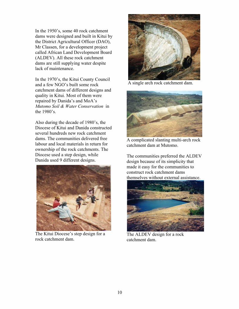
In the 1950’s, some 40 rock catchment dams were designed and built in Kitui by the District Agricultural Officer (DAO), Mr Classen, for a development project called African Land Development Board (ALDEV). All these rock catchment dams are still supplying water despite lack of maintenance. In the 1970’s, the Kitui County Council and a few NGO’s built some rock catchment dams of different designs and quality in Kitui. Most of them were repaired by Danida’s and MoA’s Mutomo Soil & Water Conservation in the 1980’s. Also during the decade of 1980’s, the Diocese of Kitui and Danida constructed several hundreds new rock catchment dams. The communities delivered free labour and local materials in return for ownership of the rock catchments. The Diocese used a step design, while Danida used 9 different designs.
The Kitui Diocese’s step design for a rock catchment dam.
A single arch rock catchment dam.
A complicated slanting multi-arch rock catchment dam at Mutomo. The communities preferred the ALDEV design because of its simplicity that made it easy for the communities to construct rock catchment dams themselves without external assistance.
The ALDEV design for a rock catchment dam.

11
1.6 Lessons learned Positive observations The rural communities in Kitui and Mwingi prefer rock catchments more than any other type of water supply, except roof catchments, because rock catchments have the advantages of: 1) Even small rain showers falling on rock catchments produce large volume of run-off water that can easily be drawn from their reservoirs. 2) Maintenance is simple and cheap; the catchment area and reservoir should be swept and water taps replaced before rainy seasons. 3) Rock catchment dams do not occupy Farmland but only rocks that are nobody’s property. However, for construction of earth dams near rocks, the ownership must be settled before any activities take place. 4) People have been used to draw water from rock catchments since the first structures were built in the middle of the 1950s.
A girl drawing water directly from the reservoir of a rock catchment dam.
Negative observations 1) The evaporation losses are so high in open dam reservoirs that in extreme cases half of the water may be lost to evaporation. Reservoirs can be roofed to reduce evaporation but it requires good design and workmanship. 2) Water quality may be below WHO standards, but that is acceptable by the communities concerned. The sun’s ultra-violet rays on exposed water sterilize water to an unknown standard. 3) Mosquitoes breed in the water of open dam reservoirs, thereby spreading malaria. This can be prevented by one of three methods;
a) Roof open dam reservoirs. b) Raise Tilapia Nilotica fish in the
water reservoirs.
c) Pour a few litres of clean oil onto the surface of a water reservoir.
7) Tanks and masonry dams provide domestic water, but are not capable of supplying water for livestock or irrigation due to their high demands. 8) Water fpr livestock and irrigation can be provided from earth dams situated at the foot or near rocks. Clean water for domestic use can be drawn from earth dams by means of a hand-dug well sunk in a seepage area downstream of dam walls.

12
2 COMMUNITY PARTICIPATION
2.1 Social and cultural considerations
Experience has shown that where only a narrow technical focus is adopted, many projects have failed. The reasons for the failures are varied; sometimes the high cost of the systems prevents continued implementation and replication once donor funds for the pilot project have dried up. At other times, communal systems fail because responsibility for the management, maintenance and repair of the system has not been clearly defined. A key factor in project success is community involvement at every stage from inception to long-term maintenance and operation. Involvement in planning and construction phases will not only help to build skills and a sense of self-reliance within communities, but also prepare the community better for any future maintenance and repair work. For a rock catchment system to succeed, it must address a real felt need within a community and be socially acceptable. The administrative and leadership capacity within a community is also important factors influencing the prospects for communal water projects. In Kenya, the tradition of Harambee (to pull together) on communal self-help projects has greatly assisted many villages with the affordable implementation of rock catchment dams.
In the semi-arid Machakos and Kitui in Kenya, the Wakamba communities have organized themselves into self-help groups, called Mwethya, many decades ago. They know that by working together they can cope with the harsh climatic conditions. This self-help spirit, combined with lack of fresh groundwater, has been the main drive in the construction of the hundreds of rock catchments built in that region for the last 50 years. Since boreholes not situated next to riverbeds provide saline water, people prefer drinking rainwater from rocks and roofs because it is cleaner than water from hand-dug wells, ponds and earth dams. Promotion of rock catchments in regions where these structures are unknown should include a study tour for their leaders to go to Kitui or Mwingi to see for themselves the benefits of rock catchments.
A community building their rock catchment dam at Wote in 1996.

13
2.2 Health issues Although Water is Life, contaminated water may cause illness - and perhaps death. Rural people in arid and semi-arid regions often says water is water meaning that all water, whether clean or contaminated, is drinkable. As a matter of fact, people used to drink contaminated water rarely get sick from it. The reason seems to be that the constant exposure to germs and bacteria has made the people immune. Understandable, people having insufficient water supply consider quantity more important than quality. Women and girls often often have to fetch water on their backs many kilometers from home – and often that water is contaminated by people and animals sharing the same water in an unlined waterhole or an earth dam. Although water in rock catchments without roofs is being sterilized partly by the Sun’s ultra-violet rays, the water quality can be improved by carrying out the following maintenance procedures: a) The surface of the rock
catchment should be swept before rainy seasons.
b) Silt traps should be emptied after
inflow of run-off water. c) Water reservoirs should be
emptied and cleaned before rainy seasons.
d) People should not enter water
reservoirs for drawing water but take it from tap stands.
e) Baboons, which loves rock
outcrops, must be kept out of catchments and reservoirs.
f) Mosquito breeding can be
eliminated by raising Tilapia Nilotica fish in the reservoirs.
A new and proven method of sterilizing drinking water, called SODIS (Solar DISinfection), has been developed recently with the arrival of drinking water in transparent plastic bottles. The SODIS method consists of filling empty transparent bottles with unclean water and exposing it to sunshine for at least 5 hours. The Sun’s ultra-violet rays kill off all germs and bacteria within that period. This method is cheaper and more environment-friendly than using firewood or charcoal to boil water for drinking.
Water can be sterilized in a transparent plastic bottle by the Sun’s UV rays. Should water contain dust or dirt particles, these can be made to settle by applying a few drops of seed oil from a Moringa oleifera tree, also called the Horseradish Tree or the Drumstick Tree that grows well in dryland.

14
2.3 Cost benefits The cost benefits of rural water supplies comprise three components, namely: a) The construction cost of the
water project. b) The annual cost (recurrent) of
maintenance and repair of the water project.
c) Compare the construction and
recurrent costs of rock catchments with conventional methods of obtaining water such as boreholes, large earth dams or water sold by vendors.
The economic viability of rock catchments depends on the cost of conventional water sources. The local inhabitants can usually evaluate whether a rock catchment is the best option than for them Comparison of cost of 3 types of rock catchments Earth dams are the cheapest type to construct using manual labour or animal draught.
The disadvantages of earth dams are loss of water by seepage and evaporation, and much maintenance due to: a) Spillways get eroded by
overflowing surplus water.
b) Dam walls get damaged by
grazing livestock. c) Dam reservoirs get silted up if
the silt traps are not cleaned. Rubble-stone masonry dams that gain free storage capacity from natural rock pools or gorges are cheap to construct and maintain.
These dams have no seepage losses but half of the volume of water might evaporate. Evaporation can be prevented by roofing the reservoirs, as seen below, but that doubles the construction cost.
Water tanks are the most expensive type of rock catchments to construct but since they have no seepage loss or evaporation loss their disadvantage is limited storage capacity of water.

15
2.4 Environmental feasibility and impact Feasibility The environmental feasibility depends on two items; a) Availability of rock outcrops,
such as whalebacks, inselbergs, pediments, koppies, grund-level rocks and underground rocks
b) Rainfall, even low and erratic
showers can supply large volume of water provided the rock area is sufficient large to compensate for the low rainfall.
Remember; 1 acre of rock surface can produce 2.4 million liters of water on 600 mm of rainfall.
Impact No negative environmental impact is known for rock catchments. A positive impact is that rock catchments harvest rainwater that otherwise would create soil erosion and flooding problems for people living adjacent to the rocks. 2.5 Gender issues Until recently, one of women’s many responsibilities was to fetch water, often far from their homes. This gender issue is now slowly changing. In places where bicycles are affordable, it is often the men who fetch water by carrying 2 or 3 jerry-cans of water on their bicycles. If a husband is working far away from the homestead, the wife can usually ride the bicycle for fetching water.
A man fetching water on a bicycle.
A woman coming home with water. It can sometimes be difficult to improve or construct a water project but by following the line of command in the administrative establishment, most obstacles can be overcome. Usually communities have already organised themselves into either: a) Women groups consisting of women only. These groups are usually well organized, reliable and always interested in water projects that can shorten the distance for fetching water. b) Self-help groups consist of both men and women. The majority of committee members are usually men, while women being a minority. Since fetching water is the responsibility of women, they should be represented equally with men in committees.

16
2.6 Administrative guidelines A self-help group, or a women group, is managed by a committee that has been elected by a group of people who have common interest in, for example; the construction of a rock catchment. A committee consists of: a) A Chairperson, who is usually an
elderly and articulate person. b) A Treasurer, who is a person
trusted in money matters and in keeping records.
c) A Secretary, who can speak, read
and write English. d) Deputies for each of the three
persons mentioned above. e) A committee might have a
Patron, who can be a respected politician or a well-to-do businessman capable of assisting the group with approvals or finances.
f) The Assistant Chief of the area is
also a member of self-help- and women groups.
g) Preferably, half of the committee
members should be women. For a group to obtain an official status, it must be registered with the relevant department under a ministry dealing with community development.
Nowadays in Kenya, proposals for renovation and construction of water projects are presented to one of the 7 Water Services Boards (WSBs) covering the parts of the country shown below.
WBS addresses are: Athi WSB, Box 45283, 00100 Nairobi Tana WSB, Box 1343, Nyeri Coast WSB, Box 90417, Mombasa L.Victoria South, Box 3325, Kisumu L.Victoria North, Box 673, Kakamega Rift Valley WSB, Box 220, Nakuru Northern WSB, Box 495, Garissa
A self-help group stands where the wall for their rock catchment dam will be constructed.

17
2.7 Writing a proposal for a rock catchment project When a community has decided they need a rock catchment dam or tank, the following guidelines can assist them to write a proposal for a rock catchment project that can be presented to their WSB. First state the name, postal address and physical location of the proposed project. Add some committee members’ telephone numbers. Then state the number of people who will benefit from the project and the size of the area in which they live. Explain where they are fetching water at present and the benefits they will gain from the proposed project. Thereafter describe the water project in words and with a design sketch and a bill of quantity (BQ) that shows the required materials and labour. Then estimate the cost of materials and labour and present it as a budget divided into two sections: a) The cost of items to be purchased,
such as technical assistance, tools, training, materials, transport, etc.
b) The value of providing local labour
and local materials that will be provided free of charge by the community. This value should amount to about 15% of the total cost of training and construction.
Thereafter explain how the community will manage the funds for the training and construction works as well as for future maintenance of the project.
Should it be too difficult for a committee to write an acceptable proposal, the WSB might recommend somebody who can write the proposal for a fee to be paid by the community. When the project proposal been discussed and approved by the community members, the final proposal is presented to the Water Service Board covering that area.
A design sketch of a rock catchment dam. After some time when the project proposal has, hopefully, being approved and financed by WSB, the detailed survey, design and construction work can be implemented by a consultant or contractor approved by the WSB. In the unlikely event of WSB turning down the proposal, then the committee has to solicit funds from elsewhere. If a donor agency cannot be found to sponsor the implementation, then the required funding has to be raised locally. This may not be an easy task, but some suggestions are mentioned on the next page.

18
2.8 Methods of raising funds locally
Some time ago, the method of raising funds was to contact a donor and request them to finance a proposal. Nowadays, most donors give their money to WSBs. If therefore a proposal has not been granted by the WSB, the community must finance their project themselves. In order to minimise the construction cost, a community can select one of the 3 low-cost types of water projects listed below. Each one of them require only a few bags of cement but much unskilled labour that can be supplied free of charge by a community itself. a) A rock catchment dam made by
removing the vegetation and soil covering a rock pool. If required, the pool can be enlarged with a low wall built of rubble-stone masonry.
b) A subsurface dam built of soil with
a hand-dug well in a dry riverbed. c) A small earth dam (pond) built of
soil and equipped with a hand-dug well.
These 3 types of water projects can be constructed in stages depending on the availability of cash and labour. The best season for construction work is after harvest when crops can be sold for cash and people are not busy in their fields. Another incentive is that the demand for water is at it highest during dry seasons. The techniques for locating suitable sites, sketching designs, estimating costs and learning construction procedures can be found in this series of handbooks. Although these 3 types of water projects are cheap to construct, cash is not easily
found in the country side. People keep their capital in livestock and land holdings because the interest gained from bank accounts is too small compared with the value of offspring of livestock. Nevertheless, rural people can still donate some cash from selling livestock or farm produce when they consider the matter sufficient urgent. The usual methods of fund raising are:
1) Cash raised at Harambee meetings for e.g. students going for further studies, construction of churches and schools or payment of someone’s hospital bill or funeral.
2) Monthly fees from members of a self-help group.
3) Merry-go-around payments.
4) Income from a self-help group’s activities, such as making burnt bricks, sand, stones and ballast, rearing goats and chicken, selling tree seedlings, weaving baskets and ropes, selling water from rock catchments, etc.
5) Fines paid by members for being absent or late or failing to carry out tasks given by a self-help committee.

19
3 ROCKS SUITABLE FOR ROCK CATCHMENTS 3.1 Suitable types of rocks Most ASAL and desert regions have suitable rocks for rock catchments. Some rock surfaces are exposed while others are invisible due to being covered by soil and vegetation. Long narrow rocks of granite raising from flat land are called whalebacks
as this whaleback situated in Tzavo. Inselbergs are large dome-shaped rocks protruding from flat land
as this inselberg at Voi.
Hills with exposed rock surfaces at the highest end are called pediments
as this pediment at Sagalla.
Rocks protruding from the ground are called kopjes as this at Dodoma.
Ground-level rocks are, naturally, situated just above ground level such as this ground-level rock at Taveta. Underground rocks can usually be identified by the stunted growth of vegetation in the soil covering a rock
such as this underground rock where some of its soil cover being removed at Wote.
20
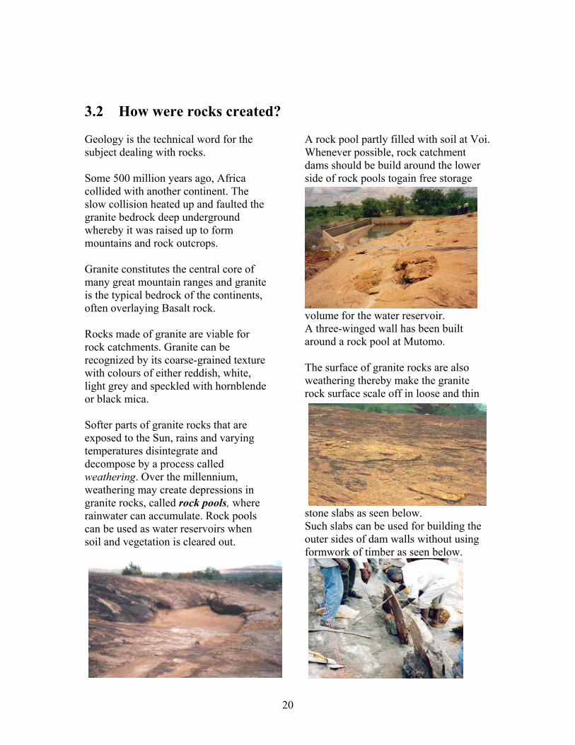
3.2 How were rocks created? Geology is the technical word for the subject dealing with rocks. Some 500 million years ago, Africa collided with another continent. The slow collision heated up and faulted the granite bedrock deep underground whereby it was raised up to form mountains and rock outcrops. Granite constitutes the central core of many great mountain ranges and granite is the typical bedrock of the continents, often overlaying Basalt rock. Rocks made of granite are viable for rock catchments. Granite can be recognized by its coarse-grained texture with colours of either reddish, white, light grey and speckled with hornblende or black mica. Softer parts of granite rocks that are exposed to the Sun, rains and varying temperatures disintegrate and decompose by a process called weathering. Over the millennium, weathering may create depressions in granite rocks, called rock pools, where rainwater can accumulate. Rock pools can be used as water reservoirs when soil and vegetation is cleared out.
A rock pool partly filled with soil at Voi. Whenever possible, rock catchment dams should be build around the lower side of rock pools togain free storage
volume for the water reservoir. A three-winged wall has been built around a rock pool at Mutomo. The surface of granite rocks are also weathering thereby make the granite rock surface scale off in loose and thin
stone slabs as seen below. Such slabs can be used for building the outer sides of dam walls without using formwork of timber as seen below.

21
3.3 Components of rock catchments When looking for suitable sites for rock catchments, keep in mind that rock catchments consist of four components: 1) A catchment area of clean rock surface from where rainwater can run off without obstruction. Rocks can be cleaned by removing soil, vegetation, stones and loose parts from the surface. Large fissures can be sealed with cement mortar or concrete. Smaller cracks can be sealed with Bitumen.
An uncleaned rock catchment at Sagalla.
2) Garlands of gutters divert rainwater run-off from a catchment to a water reservoir. Gutters can also be used to increase the catchment area of rocks.. Aqueducts can deliver water from gutters to water tanks and run-off water from adjacent rock surfaces to the main catchment area.
A garland of gutter at Kasigau.
An aqueduct gravitating run-off water from a rock to a tank at Kibwezi. 3) A water reservoir that can be a water tank, a rock catchment dam, as seen below, or an earth dam.
4) Extraction of water from rock catchment dams consists of gravitating water via a pipe to a tap stand at the foot of the rock.
A tap stand with a self-closing watertap made locally in Mutomo.

22
3.4 Where to find suitable sites for rock catchments For a layman, it may be difficult to imagine how the shapes of a rock can be utilised for harvesting and storing rainwater because most rocks are covered with vegetation making it difficult to see the potential places for catchments and reservoirs. Each of the three types of rock catchments has its specific site criteria that are explained in the following chapters:
Chapter 6 deals with water tanks.
Chapter 7 describes masonry dams,
Chapter 8 deals with earth dams at rocks Generally, all three types of rock catchments can be constructed at almost any type of rock outcrops provided they can produce the required volume of rainwater run-off. However, as explained in Chapter 7, masonry dams are more site-specific than tanks and earth dams because: Gorges between two rocks can be closed with a straight dam wall. Rock pools and rock shelves, the latter being nearly flat areas on rock outcrops, can be surrounded with two-winged or three-winged dam walls. Despite being site-specific, masonry dams have the following advantages over water tanks and earth dams: • They can be constructed in stages
according to the availability of funds and community labour.
• They have no problems of
erosion. • Maintenance consists only of
sweeping the catchment area before rains and occasional replacement of watertaps.
• They have no ownership dispute. • They do not occupy farm-or
grazing land.

23
4 Relation between catchment areas and reservoirs It is important that the catchment area of a rock and the seasonal rainfall of that region can fill its water reservoir. While the catchment area can be known by following the advice in the next chapter, the rainfall in arid and semi-arid regions may vary from 100 mm to 1,000 mm in a season, although its seasonal average is quoted as, say 300 mm. The consequences are that if a catchment is too small and the rainfall is average, then its reservoir will not be filled up with water. On the other hand, if a catchment is too large and the rainfall is average, then most of the run-off water will be wasted by spilling over the water reservoir. It is therefore a balancing act to determine the correct size of a catchment area due to the unpredictable rainfall. Experience has shown that most communities prefer their rock catchment to spill-over with water when the rainfall is average rainfall and above, instead their reservoir not filling up with water when the rainfall is below average and when water is in short supply everywhere. Three factors can be used to estimate the volume of run-off water from a rock catchment: 1) Seasonal rainfall. 2) Evaporation loss from rains falling on rock surfaces. 3) Size and slope of a catchment area. 4.1 Seasonal rainfall Where the average rainfall of a season is known it is wise to use only half of that figure. For example, divide a seasonal rainfall of 300 mm with 2 = 150 mm and use that figure for calculation the volume of rainwater run-off. 4.2 Evaporation loss from rains falling on rock surfaces Almost all rainwater runs off rocks because they have a hard surface which water cannot infiltrate. However, some 15% of the rainwater might evaporate when it falls on rocks heated by the Sun during daytime. Since most rains fall at night or early mornings in the tropics, it can be assumed that the nightly evaporation loss is about 5 %. The evaporation loss might therefore be about 10% on average. 4.3 Size and slope of catchment areas A simple method to measure a catchment area is to use the known practice of one acre of land is a square measuring 70 steps on all four sides. When each step has length of 1 yard, equal to 3 feet or 91.5 cm, then 91.5 cm x 70 steps = 64,05 m x 64,05 m = 4,102 square meters which is close to the 4,047 square metres being the correct area of 1 acre. When the area of a catchment is known in square meters, then multiply with 4,047 to convert the area from acres to square meters.
A more accurate method consists of measuring the boundaries of a catchment area and the distances in between the boundaries using a long tape-measure and millimetre paper to draw a sketch as shown below to the left.
24
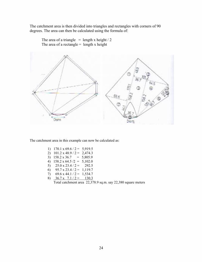
The catchment area is then divided into triangles and rectangles with corners of 90 degrees. The area can then be calculated using the formula of:
The area of a triangle = length x height / 2 The area of a rectangle = length x height
The catchment area in this example can now be calculated as:
1) 170.1 x 69.6 / 2 = 5,919.5 2) 101.2 x 48.9 / 2 = 2,474.3 3) 158.2 x 36.7 = 5,805.9 4) 158.2 x 64.5 /2 = 5,102.0 5) 25.0 x 23.4 / 2 = 292.5 6) 95.7 x 23.4 / 2 = 1,119.7 7) 69.6 x 44.1 / 2 = 1,534.7 8) 36.7 x 7.1 / 2 = 130.3
Total catchment area 22,378.9 sq.m. say 22,380 square meters

25
Since the volume of rainfall falling on a sloping surface is less per square meter than on a horizontal surface, the following percentage of square meters has to be deducted from a sloping catchment area. 90 degrees gradient minus 100 % 80 degrees gradient minus 86 % 70 degrees gradient minus 68 % 60 degrees gradient minus 47 % 50 degrees gradient minus 38 % 40 degrees gradient minus 23 % 30 degrees gradient minus 13 % 20 degrees gradient minus 5 % 10 degrees gradient minus 2 %
A protractor for measuring slopes
The gradient of a sloping rock catchment can be found using a transparent protractor with a bolt or small stone tied to the centre of it with a string. When the string is aligned with the 90 degree mark at the bottom of the protractor, the gradient of the rock can be seen by looking at the rock through the scale on the transparent protractor 4.4 Example of run-off water from a catchment of rock 1) An average seasonal rainfall is quoted as 300 mm.
As explained earlier, divide the figure by 2 = 150 mm. 2) The catchment area is 22,379 sq.m. and has a gradient of 40 degrees.
According to the sketch above; a 40% sloping catchment receives 23 % less rainfall than a horizontal catchment. The horizontal catchemtn area is therefore: 22,379 sq.m. x 23 = 5,147.17 horizontal sq.m. 100
3) The evaporation loss is 10 %. Therefore the volume of run-off in this example will be: 150 mm rain x 5,147.17 horiz.sq.m. - 10 % loss = 694,868 litres = 694,9 cu.m. water. 1,000 As a rule of thumb, the storage volume of a reservoir for, say, 695 cu.m. of water can be reduced with 20% due evaporation and consumption of water from the reservoir during the rainy season. Therefore, if the total seasonal run-off is 695 cu.m., then the reservoir should have a storage volume of: 695 cu.m. x 20 = 126 cu.m. which is deducted from 695 cu.m. to get 100 the correct answer that the reservoir should have a storage volume of 569 cu.m.

26
4.5 Tools and equipment for survey and design The type of tools and equipment required for carrying out surveys of rock catchments depends on the surveyor’s level of sophistication. Since this handbook advocates low-cost and do-it-yourself techniques, the tools and equipment listed below will be sufficient for the task. Item Specification Quantity Approx. US$ Note book Any 1 nos. 1 Ball pens 3 colours 3 nos. 2 Tape measure 30 metres long 1 nos. 8 Protractor Transparent with
string and nut 1 unit 2
Spirit level About 120 cm long 1 nos. 3 Timber with 2 legs 100 cm long + legs 1 nos. 1 Mason hammer Any 2 nos. 3 Transparent hosepipe
1 metre of 12 mm to 18 mm diameter
1 length 1
Transparent hosepipe
30 metres or more 1 length 10
Builders' line 50 metres 1 length 2 Calculator Any 1 nos. 5 Graph paper A3 Millimetres 1 pad 4 Drawing board Size A3 1 unit 70 Drawing equipment Secondary schools 1 set 10 White oil paint 1 litre 1 tin 8 Water Drinking 5 litres 6 Approx. Total 136

27
5 How to estimate the volume of dam reservoirs When a design and its construction cost have been made for a rock catchment dam or an earth dam, the volume of its water reservoir should be known so that it can be estimated whether it is economically viable to construct the dam. Water reservoirs for rock catchments and earth dams can have many shapes. It is therefore a little complicated to estimate the volume of such water reservoirs. However, the following guidelines describe two methods on how to estimate the volume of dam reservoirs. 5.1 The simplest method The volume of dam reservoirs can roughly be estimated using a simple formula: Volume = width of reservoir x depth of reservoir x length of reservoir / 6 For example: The maximum width (w) of the reservoir is 20 meters. The deepest part of the reservoir (d) is 4 metres and the length of the reservoir (l), also called the throw-back, is 60 metres. Therefore: (w) 20 m x (d) 4 m x (l) 60 m / 6 = 800 cubic metres 5.2 A more precise but complicated method The volume of a water reservoir can be estimated more precisely by dividing it into horizontal layers spaced 100 cm apart. The upper and lower area of each layer is measured and its area calculated in square meters. When the two areas are added together and divided by 2, it gives the volume in cubic meters of the section between these two layers. When the volume of all the sections in the dam reservoir are added together, the total volume of the water reservoir is known. Practically, this method can be applied by marking the maximum water level onto the sides of the rock, or an earth dam, using either a long transparent hosepipe filled with water as seen on the photo below or -

28
- or use a short length of a transparent hosepipe bent into a circle and filled halfway with water as shown above. The two water-levels in the transparent plastic pipes give two exact horizontal levels that can be used for sighting and marking the horizontal level of a water reservoir filled to its maximum with water.
With the maximum water level marked for every 5 meters, or so, onto the sides of a water reservoir, the following measurements can be taken. Knots are made for every 5.0 meters on a long nylon string. The string is then inserted in the hook of a 30 meter long tape-measure and drawn tightly across the longest section of the dam reservoir at the height of the maximum water level. The tape-measure hanging in the nylon string can now be used for taking vertical measurements from the string drawn at the maximum water-level to the bottom of the reservoir for every knot at 5 meters on the string. Similarly, the tape-measure is used for taking horizontal measurements from the nylon string to each side of the marked maximum water level of the water reservoir. The vertical and horizontal measurements can now be transferred to a millimetre graph paper in scale 1:100 as shown below.

29
By counting and adding together the numbers of full, half and quarter squares within the drawn lines, the surface area and volume for each of the 100 cm high sections and the total volume of the water reservoir can be found in cubic meters.
In this example, the total volume of the water reservoir was found to be 1,202 cu.m.
5.3 Tools and equipment for survey and design The type of tools and equipment required for carrying out surveys of water reservoirs depends on the surveyor’s level of sophistication. In this handbook for do-it-yourself the tools and equipment listed below will be sufficient for the task. Item Specification Quantity Approx. US$ Note book Any 1 nos. 1 Ball pens 3 colours 3 nos. 2 Tape measure 30 metres long 1 nos. 8 Transparent hosepipe From ½” to 1” 50 meters 25 Builders' line 50 metres 1 length 2 Calculator Any 1 nos. 5 Graph paper A3 Millimetres 1 pad 4 Drawing board Size A3 1 unit 70 Drawing equipment Secondary schools 1 set 10 Water Drinking 5 litres 6 Approx. Total 133

30
6 Water tanks 6.1 Site criteria for rock catchment tanks Water tanks can be constructed at almost any rock outcrop provided the tank can be placed on firm ground at a lower elevation than the catchment. The rainfall and area of a catchment should be sufficient large to fill a tank from a rain shower of, say 20 mm. To fill a 50,000 litres (50 cu.m.) tank on 20 mm rain, the catchment must have an area of: 50,000 litres / 20 mm rain + 10 % evaporation loss = 2,750 sq.m.= about 2/3 of an acre.
A 50 cu.m. rock catchment tank at Kibwezi. A similar rock catchment tank at Lakipia Water tanks that collect and store rainwater run-off from rocks are being used in many places because the technique is easy to understand and local builders usually know how to construct water tanks. However, the constraints with rock catchment tanks are: a) they can only storage a limited volume of water and therefore dry up in a few weeks, and b) they are expensive compared with masonry dams and earth dams. It is an economical advantage to build water tanks with a height not exceeding 200 cm. If water tanks are built with a height of more than 200 cm they require more reinforcement than recommended in this handbook. 6.2 How to estimate the volume of a cylindrical tank The volume of a cylindrical water tank is calculated using the formula of: Volume = radius x radius x 22 x height = r x r x 22 x h = r2?h
7 7 The volume of a 50,000 litres tank is therefore calculated as: Radius 283 cm x radius 283 cm x 22 x height 200 cm = 50,342 litres (50.342 cu.m.). 7
31
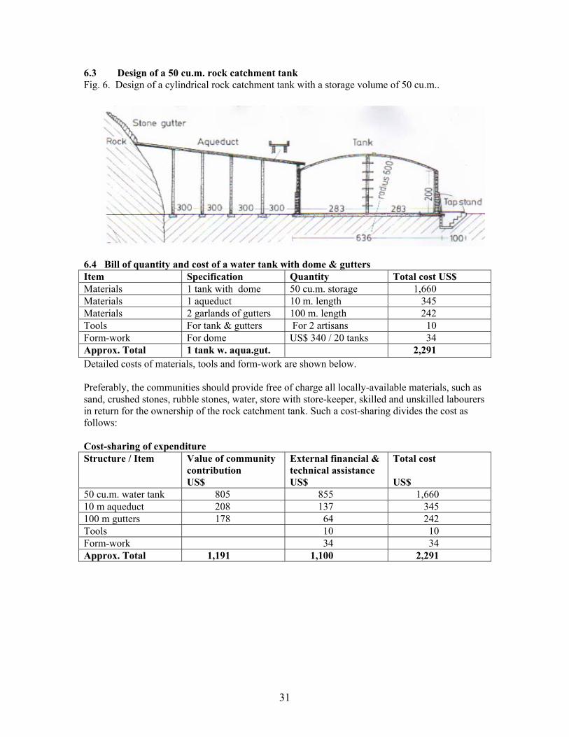
6.3 Design of a 50 cu.m. rock catchment tank Fig. 6. Design of a cylindrical rock catchment tank with a storage volume of 50 cu.m..
6.4 Bill of quantity and cost of a water tank with dome & gutters Item Specification Quantity Total cost US$ Materials 1 tank with dome 50 cu.m. storage 1,660 Materials 1 aqueduct 10 m. length 345 Materials 2 garlands of gutters 100 m. length 242 Tools For tank & gutters For 2 artisans 10 Form-work For dome US$ 340 / 20 tanks 34 Approx. Total 1 tank w. aqua.gut. 2,291 Detailed costs of materials, tools and form-work are shown below. Preferably, the communities should provide free of charge all locally-available materials, such as sand, crushed stones, rubble stones, water, store with store-keeper, skilled and unskilled labourers in return for the ownership of the rock catchment tank. Such a cost-sharing divides the cost as follows: Cost-sharing of expenditure Structure / Item Value of community
contribution US$
External financial & technical assistance US$
Total cost US$
50 cu.m. water tank 805 855 1,660 10 m aqueduct 208 137 345 100 m gutters 178 64 242 Tools 10 10 Form-work 34 34 Approx. Total 1,191 1,100 2,291

32
Bill of quantity and cost of materials for a 50 cu.m. water tank Item Specification Quantity Approx. US$ Cement 50 kg bags 50 bags 400 Sand Coarse river sand 15 tonnes 150 Water 200 litres oil-drum 25 oil-drums 75 Crushed stones 10 to 20 mm 6 tonnes 180 Rubble stones 10 to 15 cm 10 tonnes 10 Rubble stone blocks 40 x 19 x 14 cm 510 blocks 150 Weld-mesh No.8, 2.4 m x 1.2 m 30 sheets 200 Barbed wire Gauge 12.5 4 rolls @ 20 kg 100 Galvanised pipe 18 mm 3 metres 20 Round iron bars 12 mm 96 metres 50 PVC pipe 100 mm 3 metres 10 Skilled labour Masons 2 masons x 15 days 180 Unskilled labour Trainees 3 persons x 15 days 135 Approx. Total 1,660 Bill of quantity and cost for 10 metres of aqueduct Item Specification Quantity Approx. US$ Cement 50 kg bags 10 bags 80 Sand Coarse river sand 10 tonnes 10 Water 200 litres oil-drum 5 oil-drums 15 Crushed stones 10 to 20 mm 5 tonnes 15 Rubble stone blocks 40 x 19 x 14 cm 160 blocks 48 Weld-mesh 2.4 m x 1.2 m 5 sheets 33 Skilled labour Masons 2 x 6 working days 72 Unskilled labour Trainees 4 x 6 working days 72 Approx. Total 345 Bill of quantity and cost of 100 meters of stone gutters Item Specification Quantity Approx. US$ Cement 50 kg bags 8 bags 64 Sand Coarse river sand 6 tonnes 6 Water 200 litres oil-drum 4 oil-drums 12 Flat rubble stones 20 to 40 cm long 8 tonnes 8 Irregular stones 10 to 20 cm 8 tonnes 8 Water 200 litres oil-drums 8 oil-drums 24 Skilled labour Mason 1 x 10 days 60 Unskilled labour Trainees 2 x 10 days 60 Approx. Total 242

33
Tools for building a tank of blocks with a dome of ferro-cement Item Specification Quantity Approx. US$ Tape measure 3 m long 1 4 Mason hammers Medium 2 6 Mason trowels Medium 2 8 Square trovels Steel 2 10 Mason chisels Flat 2 6 Wooden floats Medium 2 4 Straight edge 2 m long, 8 x 5 cm 1 2 Spirit level 120 cm long 1 6 Shovels Medium 3 12 Pick-axe Medium 1 6 Mould for blocks 40 x 19 x 14 cm 1 36 Approx. Total 100 Since the tools can be used for building at least 10 water tanks, the cost of tools for 1 tank is about US$ 100 / 10 tanks = US$ 10 Tools and materials for form-work for a dome of ferro-cement Item Specification Quantity Approx. US$ Carpenter saw Medium 1 5 Carpenter hammer Medium 1 3 Brace w. drill bits 9 mm drill bits 1 6 Old oil-drums Made to flat sheets 30 sheets 160 Timber 275 x 20 x 2.5 cm 12 lengths 50 Timber 190 x 8 x 5 cm 12 lengths 40 Timber 180 x 8 x 5 cm 12 lengths 40 Bolts 8 mm, 15 cm long 12 4 Plastic basin 50 cm diameter 1 2 Skilled labour Carpenter 5 days 30 Approx. Total 340 The form-work for the construction of a dome of ferro-cement can be reused for building about 10 domes, thereby reducing the cost for 1 tank to US$ 340 / 10 tanks = US$ 34

34
6.5 Construction of a water tank built of rubble stone blocks Rubble stones found near the rock are compacted into concrete mixed of 1 part of cement to 4 parts of sand and 4 parts of ballast (crushed stones) in a mould.
The rubble stones save about 50% of the cost of cement, sand and ballast. The circular foundation for the tank is excavated down to firm soil and levelled using a spirit level on a straight edge. A 8 cm thick layer of concrete of mixture 1:4:4 is compacted onto the dry surface of the excavation. Weld-mesh is then cut, tied together and laid on the concrete.
The draw-off pipe is tied onto the weld-mesh with a wire and a 7 cm thick layer of concrete 1:4:4 is compacted onto the weld-mesh and levelled with a rough surface.
After a couple of days, the rubble stone blocks are laid in a circle with equal spacing on the foundation using a radius wire attached to a pipe placed in the centre of foundation.
The blocks are mortared onto the foundation and to each course with mortar of a mixture of 1:4 without cutting any of the blocks. When the tank has been built to its final height, barbed wire, gauge 12.5, is wrapped tightly around the wall in a spiral spaces 5 cm at the lower half of the tank and 10 cm at the upper half. The barbed wire is pulled tight using a carpenter's hammer while being nailed onto the wall of the tank.
The tank wall is then plastered on the outer side with mortar 1:3 and covered with Polythene sheets for curing. Thereafter the inner side and the floor are plaster with mortar and NIL (cement slurry) for water proofing.

35
The form-work for a dome is made of oil-drums that are cut open, flattened, cut into shape and laid upon a framework of timbers having the curve of a 6 m radius.
A centre pillar to support the form-work and dome is made of a vertical-standing PVC pipe filled with concrete. Short horizontal lengths of G.I. pipes are inserted in the PVC pipe before concreting it to function as a ladder. The form-work is then covered with Polythene sheets or plastic sacks. Sheets of weld-mesh are cut and tied together on the form-work.
Mortar mixed of 1 part of cement with 3 parts of coarse sand is compacted onto the form-work in a 5 cm thick layer and smoothened to an even surface. A circular plastic basin with a diameter of about 50 cm is used as mould for the man-hole. .
The basin is placed on the form-work for the dome next to the pillar that will function as a ladder.
The basin is filled with concrete into which a bend iron rod is inserted as a handle in the man-hole lid. For curing the dome is covered with Polythene sheets or sacks covered with a layer of soil for 2 weeks.
Nobody should be allowed to walk or stand on the dome while being cured. An aqueduct for gravitating rainwater from the rock to the tank is constructed of a line of pillars, built of rubble stone blocks, that supports a concrete slab sloping towards the inlet of the tank.

36
6.6 Construction of stone gutters Garlands of stone gutters built onto rock outcrops have two functions: a) they divert rainwater run-off from a rock catchment area to the water reservoirs of
tanks and dams, and b) they increase catchment areas by winding their way around rocks. The lines of gutters
can even extend to the opposite side of rocks.
Run-off water from adjacent rocks can also be gravitated to a water reservoir by aqueducts and garlands of gutters provided a sufficient gradient can be obtained.
Fig. 7. Two garlands of gutters start from the aqueduct of a water tank or from the two ends of a masonry dam.
The gradient of 3:100 is marked onto a rock surface with a spirit level placed horizontally on a 100 cm length of timber that has two legs, one being 3 cm longer than the outer. Garlands of stone gutters start their upward gradient from the end of aqueducts, or the two ends of dam walls.
Fig. 8. Flat stones are supported by smaller stones that are mortared onto cleaned rock surfaces with a mixture of 1 part of cement to 3 parts of sand.

37
7 Masonry dams on rocks 7.1 The ALDEV (African Land Development) design A series of rock catchment dams were constructed of the ALDEV design during the late 1950s in Kitui, the two most famous being Ngomeni built in 1955 near Kyuso and Kaseva built in 1956 near Mutomo in Kitui. Kaseva rock catchment had a storage volume of some 3,000 cubic metres that was enlarged to about 5,000 cubic metres by a Danida project Mutomo Soil & Water Conservation in 1989. The dam reservoir has only dried up 4 times during the last 47 years, namely during the long droughts of 1975, 1985, 1995 and 2002. More than 100 rock catchment dams of the ALDEV design have been constructed in Kitui, Makueni, Taita-Taveta and Zambia without any failure by the author during the last 20 years. The success being due to the simplicity of the design that does not require any reinforcement provided the width of the foundation for a dam wall is equal to 3/5 of the height of the dam wall. Rainwater falling on a rock is diverted to the dam reservoir by two garlands of gutters built of flat stones mortared onto the rock. The garlands are also used for enlarging the catchments so even a small rain shower can provide huge volume of run-off water.
Fig. 9. A cut-through sketch of an ALDEV rock catchment dam with a garland of stone gutters. No reinforcement of the wall is required when the width of the base is 3/5 of the height of the wall because the factors of over-toppling and sliding are taken up by the weight of the dam wall. Water can be drawn by gravity through a galvanised pipe to a tap stand at the foot of the rock. A simple siphon device can lift water over a high point.
38
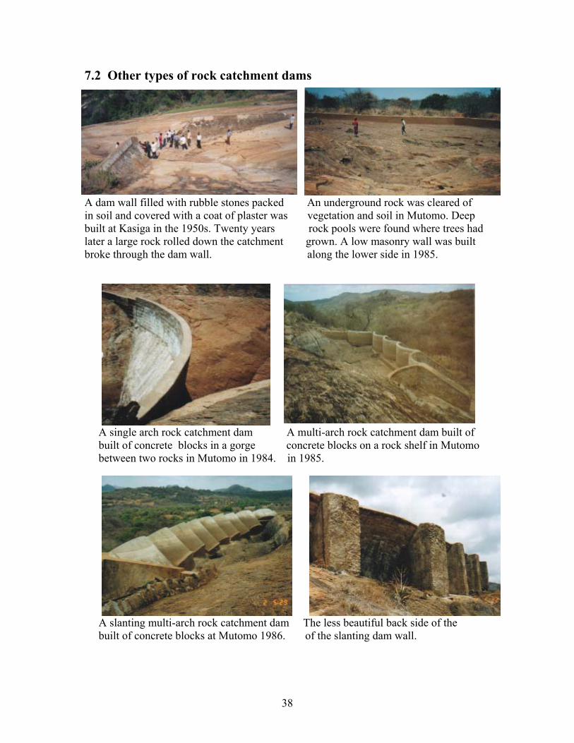
7.2 Other types of rock catchment dams
A dam wall filled with rubble stones packed An underground rock was cleared of in soil and covered with a coat of plaster was vegetation and soil in Mutomo. Deep built at Kasiga in the 1950s. Twenty years rock pools were found where trees had later a large rock rolled down the catchment grown. A low masonry wall was built broke through the dam wall. along the lower side in 1985.
A single arch rock catchment dam A multi-arch rock catchment dam built of built of concrete blocks in a gorge concrete blocks on a rock shelf in Mutomo between two rocks in Mutomo in 1984. in 1985.
A slanting multi-arch rock catchment dam The less beautiful back side of the built of concrete blocks at Mutomo 1986. of the slanting dam wall.

39
7.3 Site criteria Rock catchment dams should preferably be build on rocks that gives some free storage volume such as, gorges between two rocks, rock pools and rock shelves. 7.3.1 Single-winged masonry dams in gorges
A dam wall built in a gorge at Kasigau. Another dam wall in a gorge near Kasigau
Fig. 10. Design of a rock catchment dam built as a straight masonry wall across gorges.

40
7.3.2 Two-winged masonry dams around rock pools, in gorges and on rock shelves
A rock pool near Taveta A V-shaped dam wall with a siphon pipe built around a rock pool at Mutomo
Fig. 11. Design of a rock catchment dam with two walls constructed in gorges, around the lower side of rock pools and on rock shelves.

41
7.3.3 Three-winged masonry dams around rock pools and on shelves
A rock shelf with trees and vegetation A dam wall with three sides built on a rock not yet scooped out at Sololo, Moyale. shelf at Kisasai, Kitui.
Fig. 12. Design of a rock catchment dam with three masonry walls built on the lower side of rock pools and on rock shelves.

42
7.4 Roofs on rock catchment dams Evaporation can consume up to half of the volume of water stored in open rock catchment dams without roofing. Roofs of galvanised iron sheets can be tied onto galvanised water pipes that are anchored onto pillars built of concrete blocks in the reservoir. The disadvantages are that: a) rodents can always find their way into a dam reservoir and drown there, b) water vapour corrodes the iron sheets and wires.
A more permanent option is to erect pillars of PVC pipes filled with concrete onto which beams of reinforced concrete carrying vaulted roof sections of ferro-cement is anchored.
Fig. 13. A vaulted roof of ferro-cement covering the reservoir of a rock catchment dam.
43
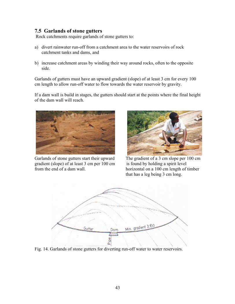
7.5 Garlands of stone gutters Rock catchments require garlands of stone gutters to: a) divert rainwater run-off from a catchment area to the water reservoirs of rock catchment tanks and dams, and b) increase catchment areas by winding their way around rocks, often to the opposite
side. Garlands of gutters must have an upward gradient (slope) of at least 3 cm for every 100 cm length to allow run-off water to flow towards the water reservoir by gravity. If a dam wall is build in stages, the gutters should start at the points where the final height of the dam wall will reach.
Garlands of stone gutters start their upward The gradient of a 3 cm slope per 100 cm gradient (slope) of at least 3 cm per 100 cm is found by holding a spirit level from the end of a dam wall. horizontal on a 100 cm length of timber that has a leg being 3 cm long.
Fig. 14. Garlands of stone gutters for diverting run-off water to water reservoirs.
44
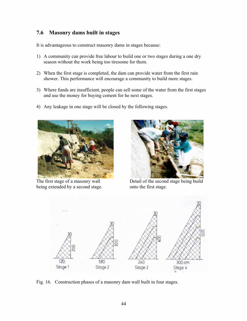
7.6 Masonry dams built in stages It is advantageous to construct masonry dams in stages because: 1) A community can provide free labour to build one or two stages during a one dry
season without the work being too tiresome for them. 2) When the first stage is completed, the dam can provide water from the first rain
shower. This performance will encourage a community to build more stages.
3) Where funds are insufficient, people can sell some of the water from the first stages and use the money for buying cement for he next stages.
4) Any leakage in one stage will be closed by the following stages.
The first stage of a masonry wall Detail of the second stage being build being extended by a second stage. onto the first stage.
Fig. 16. Construction phases of a masonry dam wall built in four stages.

45
7.7 Setting out dams walls Where a design and an estimate of the construction cost are required, the outline for the foundation of the dam wall must be marked on the rock. The site criteria are: 1) Dam walls may be build on rocks having a down- and outward slope less than 15 cm depth for every 100 cm .
The gradient of a rock is measured by holding a spirit-level horizontal on a 100 cm length of timber while measuring the distance to the rock. In this case, the gradient is more than 15 cm thereby proving that the gradient is too steep for the foundation for a dam wall.
2) Foundation for dam walls must consist of solid rock without loose parts. Loose sections of a rock surface are found by sounding the rock with a hammer. Loose parts of rocks are broken off with iron rods and hammers.
It is advisable to construct dam walls in stages with the first stage being 2 m high because: a) the dam is easy to build, b) water will be collected as soon as rains fall thereby encourage people to build the following phases and c) any leakage will be sealed by the next stage. The procedure for marking the foundation for a dam wall is as follows: Mark 2 meters height on a stick. Tie one end of a long transparent hosepipe onto the stick slightly above the 2 m mark. The stick is then hold vertically at the lowest part of the foundation while the other end of the pipe is laid on the rock towards the end of the dam wall.
Water is poured into the pipe until the waterlevel has reached the 2 m mark on the stick. The waterlevel in the other end of the pipe is now marked onto the rock. The other end of the wall is marked in the same way. Then mark with white paint both ends of the dam wall and the place with the stick, which is the lowest point of the foundation.

46
Thereafter the width of the foundation can be marked onto the rock using two design criteria: 1) The width of a foundation must always be 3/5 of the height of the dam wall. Since the first stage will be 200 cm high at the lowest point on the rock, the foundation will be 120 cm wide at that point because 200 cm divided by 3/5 is 120 cm. 2) The crest must be at least 30 cm
wide.
When the width of the foundation, 120 cm, has been marked at the lowest point and the width of the crest, 30 cm, has been marked at each end of the dam wall, strings are drawn between these points to show the outlines of the foundation. The outlines are marked with dots of white paint so that the builders can identify the correct place without problems.
Fig. 16. The outline of the foundation for a 200 cm high dam wall has been marked onto the rock with white paint.

47
7.8 Calculating the cost of constructing dam walls The cost of constructing a rock catchment dam can be calculated when the volume of its dam wall is known because that determines requirements of materials and labour. Volume of dam walls The volume of dam walls can be calculated by drawing sketches with the length and height of the dam wall bearing in mind that the base of a dam wall must always be 3/5 of its height and that the crest should always be 30 cm wide. The sketches are then divided into triangular (A) and rectangular (B) units whose volume can be calculated using the formula below. The volume of the units can then be added together to give the total volume of the dam wall.
Fig. 17. A cross section of a dam wall can be divided into a triangle (A) and a rectangle (B) as seen on the right. The formula for calculating the area of a triangle is: Area = base (b) x height (h)/2 The formula for calculating the area of a rectangle is: Area = base (b) x height (h) Fig. 18. The triangular section of a dam wall (A) can be calculated using the formula for a three-sided pyramid with a pointed end: Volume = base area x length (l) /3. Fig. 19. The rectangular part of a dam wall with a pointed end can be calculated using the formula of: Volume = base x height x length/2. Fig. 20. The middle part of a three-sided dam wall can be calculated by adding together the area of the two ends and divide the result with 2. That will give the average area of the cross section which is then multiplied with the length to get the total volume of the wall.

42
Fig. 21. An example of estimating the volume of a dam wall. The measurements of the dam wall in the example are: Height of middle wall 2.0 m Base of middle wall 2.0/ 3/5 = 1.2 m Width of crest 0.3 m Length of left wall 12.0 m Length of middle wall 10.0 m Length of right wall 14.0 m Volume of left wall Area base: Height 2.0 m x base 2.0 m/ 3/5 + height 2.0 m x base 0.3 m = 3.0 sq.m. Volume: Area base 3.0 sq.m. x length 12.0 m/3 = 12.0 cu.m. Volume of middle wall Area base as left wall: 3.0 sq.m. Volume: Area base 3.0 sq.m. x length 10.0 m = 30.0 cu.m. Volume of right wall Area base as left wall: 3.0 sq.m. Volume: Area base 3.0 sq.m. x length 14.0 m /3 = 14.0 cu.m. Total volume of the three walls Left wall 12.0 cu.m. + middle wall 30.0 cu.m. + right wall 14.0 cu.m. = 56 cu.m. =======

43
7.9 Bill of quantity and cost of dam walls When the total volume of a dam wall has been found, the numbers of cubic meters is multiplied with the required materials and labour for 1 cubic meter of rubble stone masonry which is: 75% rubble stones + 25% mortar with a mixture of 1 part of cement to 4 parts of sand. Materials and labour for 1 cubic metre of rubble stone masonry Item Specification Quantity Approx. US$ Cement 50 kg bags 4 bags 32 Sand Coarse river sand 0.7 tonne 1 Water 200 litres oil-drum 1 oil-drum 3 Rubble stones Any size up 60 cm 2.1 tonne 2 Skilled artisan Mason 1 x 2 man/days 12 Unskilled labour Trainees 2 x 2 man/days 12 Approx. Total 62 Preferably the communities should provide free locally available materials, skilled and unskilled labour as their contribution for their water project. In the above example, that amounts to US$ 30 which is about 49% of the total construction cost. Bill of quantity and cost for the 56 cu.m. dam wall shown on the former page Item Specifi-
cation Quantity for 1 cu.m.
US$ for 1 cu.m.
Quantity for 56 cu.m.
US$ for 56 cu.m.
Cement 50 kg bags 4 bags 32 224 bags 1,792 Sand River sand 0.7 tonne 1 39.2 tonne 56 Water Oil-drums 1 oil-drum 3 56 oil-drums 168 Draw-off piping from dam reser-voir
18 mm galvanised pipe with tap stand
100 m pipe, fittings and tap stand
(Average 500 for a dam reservoir)
(Average 500 for a dam reservoir)
500
Rubble stones
Any size up to 60 cm
2.1 tonne 2 117.2 tonnes 112
Skilled artisan
Mason 1 x 2 days 12 112 man /days
672
Unskilled labour
Trainees 2 x 2 days 12 224 man /days
672
Approx. Total
62 3,972 Say 4,000
Preferably the communities should provide free locally available materials, skilled and unskilled labour as their contribution for their water project. In the above example, that would amount to US$ 1,680 which is about 49% of the total construction cost.
44
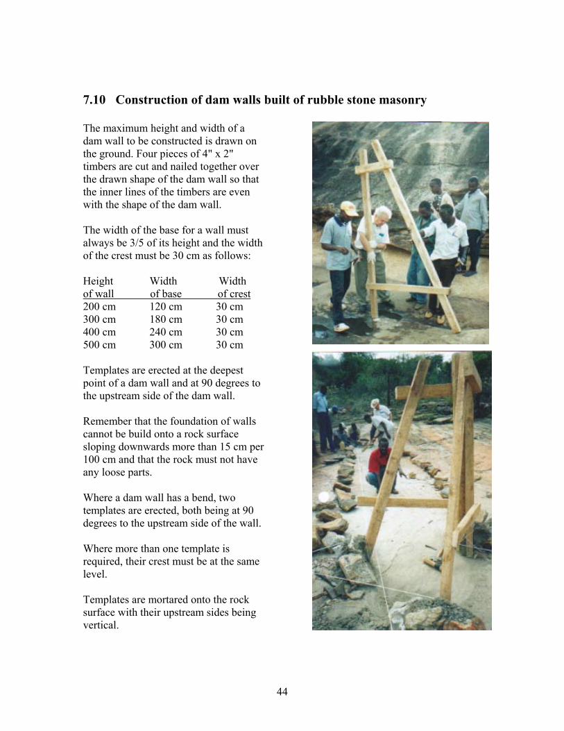
7.10 Construction of dam walls built of rubble stone masonry The maximum height and width of a dam wall to be constructed is drawn on the ground. Four pieces of 4" x 2" timbers are cut and nailed together over the drawn shape of the dam wall so that the inner lines of the timbers are even with the shape of the dam wall. The width of the base for a wall must always be 3/5 of its height and the width of the crest must be 30 cm as follows: Height Width Width of wall of base of crest 200 cm 120 cm 30 cm 300 cm 180 cm 30 cm 400 cm 240 cm 30 cm 500 cm 300 cm 30 cm Templates are erected at the deepest point of a dam wall and at 90 degrees to the upstream side of the dam wall. Remember that the foundation of walls cannot be build onto a rock surface sloping downwards more than 15 cm per 100 cm and that the rock must not have any loose parts. Where a dam wall has a bend, two templates are erected, both being at 90 degrees to the upstream side of the wall. Where more than one template is required, their crest must be at the same level. Templates are mortared onto the rock surface with their upstream sides being vertical.
45
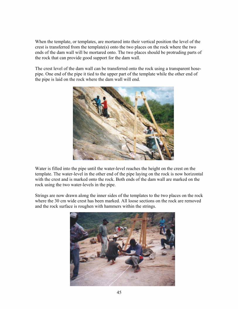
When the template, or templates, are mortared into their vertical position the level of the crest is transferred from the template(s) onto the two places on the rock where the two ends of the dam wall will be mortared onto. The two places should be protruding parts of the rock that can provide good support for the dam wall. The crest level of the dam wall can be transferred onto the rock using a transparent hose-pipe. One end of the pipe it tied to the upper part of the template while the other end of the pipe is laid on the rock where the dam wall will end.
Water is filled into the pipe until the water-level reaches the height on the crest on the template. The water-level in the other end of the pipe laying on the rock is now horizontal with the crest and is marked onto the rock. Both ends of the dam wall are marked on the rock using the two water-levels in the pipe. Strings are now drawn along the inner sides of the templates to the two places on the rock where the 30 cm wide crest has been marked. All loose sections on the rock are removed and the rock surface is roughen with hammers within the strings.

46
Rubble stones, which have been brought to the construction site, are cleaned for all dirt and soil in a wheelbarrow with water. The largest and flattest of the stones are laid out along the marked outline of the dam wall where they will be used for building the outer sides of the wall. Smaller and rounder stones are also cleaned. They will be used for filling in the wall.
. The rock surface between the strings is swept and cleaned with water thoroughly. If any dirt or loose part are left it might create leakage under the dam wall. Dry cement is then dusted onto the moist rock surface within the strings until all parts have been covered in a thin layer of moist cement. Simultaneously, mortar has been mixed of 1 part of cement to 3 parts of coarse and clean sand, called 1:3.
The mortar is laid onto the cement-dusted rock surface in a layer being about 3 cm thick (about 1 inch).
Within the same hour, mortar of mixture 1 cement to 4 sand (1:4) is made and used for mortaring the flatter stones onto the foundation along the strings. Short sticks are used to support the stones.

47
A draw-off pipe is made from a length of 1 1/2" (38 mm) galvanized iron pipe being 3 meters long with thread at one end. The surface of the pipe is roughen by a hammer to ensure a good bond with the stone masonry that will not create leakage. The draw-off pipe is concreted into in the lowest part of the dam wall in an exact horizontal position to facilitate extracting water from the dam reservoir by gravity.
After about 12 hours the mortar in two lines of stones lining the sides of the dam wall have hardened so much that the construction of the wall can continue. The space between the two lines of flat stones can now be filled with smaller and rounder stones compacted into mortar of mixture 1:4. Ensure that no stone is touching another stone without mortar because that may cause leakage.
The surface of the filled-in stones and mortar is left with a rough surface to ensure a water-tight bond with the next course of stones as seen below.
The next lines of flat stones can now be mortared onto the wall in mortar 1:4. The following day, the space between the two lines of flat stones is filled with smaller and rounder stones in mortar 1:4 and so on until the whole wall has been built up to the crest.
The upstream side of the wall and the crest are then plastered with mortar 1:3 and coated with cement slurry (NIL) for water-proofing. The downstream side do not need plastering.

48
7.11 Construction of draw-off piping Water can be drawn manually from the water reservoirs of rock catchment dams it is a tiresome and dangerous to climb up to a dam situated high above the ground and climb down again with 20 kg of water in a jerry-can on the back. Since it is fairly easy and cheap to gravitate water from rock catchment dams to tap stands at the ground level, a draw-off pipe should always be installed. Besides reducing labour and danger on drawing water, contamination of the water is also reduced because people do not enter the water reservoir. There are two types of draw-off piping, namely 1) Direct gravity flow from water reservoirs whose floors are at a horizontal or
higher level than the dam wall as shown below.
Fig. 22. Water is gravitated directly from a water reservoir situated on a rock shelf or in a gorge between two rocks by means of 18 mm galvanized piping. A perforated PVC pipe is pressed onto the upper end of the pipe that is placed in a filter box made of porous concrete blocks. The lower end of the pipe is connected to a tap stand with watertaps. The whole length of piping between the intake and tap stand is mortared onto the rock with large stones for every 5 meters or so. Although this anchoring of the pipe prevents baboons from breaking the pipe, it cannot keep elephants from pulling the pipe apart when they are thirsty and cannot enter the water reservoir.
49
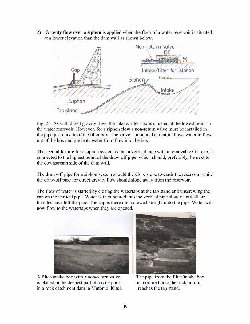
2) Gravity flow over a siphon is applied when the floor of a water reservoir is situated at a lower elevation than the dam wall as shown below.
Fig. 23. As with direct gravity flow, the intake/filter box is situated at the lowest point in the water reservoir. However, for a siphon flow a non-return valve must be installed in the pipe just outside of the filter box. The valve is mounted at that it allows water to flow out of the box and prevents water from flow into the box. The second feature for a siphon system is that a vertical pipe with a removable G.I. cap is connected to the highest point of the draw-off pipe, which should, preferably, be next to the downstream side of the dam wall. The draw-off pipe for a siphon system should therefore slope towards the reservoir, while the draw-off pipe for direct gravity flow should slope away from the reservoir. The flow of water is started by closing the watertaps at the tap stand and unscrewing the cap on the vertical pipe. Water is then poured into the vertical pipe slowly until all air bubbles have left the pipe. The cap is thereafter screwed airtight onto the pipe. Water will now flow to the watertaps when they are opened.
A filter/intake box with a non-return valve The pipe from the filter/intake box is placed in the deepest part of a rock pool is mortared onto the rock until it in a rock catchment dam in Mutomo, Kitui. reaches the tap stand.

50
7.12 Ferro-cement roofs over dam reservoirs
Fig. 23. Plan of a vaulted ferro-cement roof anchored onto beams of reinforced concrete that are supported by pillars made PVC pipes filled with concrete.
Fig. 24. Sections of a ferro-cement roof on the reservoir of a rock catchment dam. 7.13 Bill of quantity and cost of roofs The above roof has a horizontal area of about 10 m x 6 m = 60 sq.m. but due to the curved vaults the actual roof surface is larger, because the 2 m wide vaults have a surface of: D 2.0 m x 22/7/2 = 3.14 m surface instead of 2 m. The actual width of the roof area is therefore: 6 m x 3.14 m / 2 m = 9.4 m = Actual roof area of : 9.4 m x 10 m = 94 sq.m. Materials and labour for 1 sq. m. of ferro-cement roof with beams and pillars Item Specification Quantity Approx. US$ Cement 50 kg bags 0.3 bag 2.7 Sand Coarse river sand 1.0 tonne 0.3 Water 200 litres oil-drum 0.2 oil-drum 0.2 Twisted iron rod 12 mm 5 metres 2.2 PVC pipe 100 mm diameter 2 metres 3.1 Weld-mesh 2.4 m x 1.2 m 0.5 sheet 3.3 Skilled artisan Mason 0.5 man/days 3.0 Unskilled labour Trainees 1.0 man/days 3.0 Approx. Total 17.80
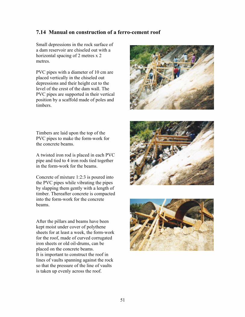
51
7.14 Manual on construction of a ferro-cement roof Small depressions in the rock surface of a dam reservoir are chiseled out with a horizontal spacing of 2 metres x 2 metres. PVC pipes with a diameter of 10 cm are placed vertically in the chiseled out depressions and their height cut to the level of the crest of the dam wall. The PVC pipes are supported in their vertical position by a scaffold made of poles and timbers. Timbers are laid upon the top of the PVC pipes to make the form-work for the concrete beams. A twisted iron rod is placed in each PVC pipe and tied to 4 iron rods tied together in the form-work for the beams. Concrete of mixture 1:2:3 is poured into the PVC pipes while vibrating the pipes by slapping them gently with a length of timber. Thereafter concrete is compacted into the form-work for the concrete beams. After the pillars and beams have been kept moist under cover of polythene sheets for at least a week, the form-work for the roof, made of curved corrugated iron sheets or old oil-drums, can be placed on the concrete beams. It is important to construct the roof in lines of vaults spanning against the rock so that the pressure of the line of vaults is taken up evenly across the roof.

52
The form-work is then covered with sheets of weld-mesh that is tied together with binding wire. Mortar made of 1 part of cement to 3 parts of clean and coarse river sand is then compacted onto the form-work in a 5 cm thick layer with the weld-mesh placed in the middle. The mortared roof is covered with polythene sheets that are covered with a layer of soil for two weeks during which nobody should be allowed to walk of stand on the roof. The polythene sheets covered with soil will retain the moisture evaporating from the mortar as droplets that drips back onto the mortar in a self-curing process. The openings between the roof and the crest of the dam wall are closed with concrete blocks and plastered. After three weeks of curing, the surface of the roof should be coated with a mixture of 1 part of cement to 10 parts of lime and water to give the roof a white paint that will cool and weather-proof the roof over the water-reservoir. Thereafter the form-work can be removed and the water reservoir cleaned before rain will fill it up.

53
Chapter 8. Ponds and earthen dams Although detailed instructions on survey, design, construction and maintenance are described in a handbook of this series Water from small earthen dams, the following information may be sufficient for some people to construct their pond or dam at a rock. 8.1 Suitable design for ponds and earthen dams Ponds and dams are suitable for harvesting run-off from rock outcrops provided they have two wide spillways capable of discharging safely large volumes of surplus water. A heavy thunderstorm in the ASAL regions is capable of delivering more than 100 mm of rain in one hour. The table below shows the volumes of run-off from 100 mm rain on three sizes of catchments. A rainy season in ASAL regions is usually about 300 mm.
Rainfall Catchment of rock Volume of run-off from rock 100 mm 1 acre = 4,049 sq.m. 404,900 litres = 404,9 cu.m. 100 mm 2 acres = 8,098 sq.m. 809,800 litres = 809,8 cu.m 100 mm 3 acres = 12,147 sq.m. 1,214,700 litres = 1,214,7 cu.m.
A curved hillside dam full of water from A self-help group desilting their Lukenya Rock near Nairobi. curved hillside dam at a rock near Voi. catchment.
Fig. 22. Design of a pond and earthen dam with two spillways for a rock
54
8.2 Design criteria The recommended curved design with two spillways has additional advantages:
1) The hemi-spherical shape of the water reservoir gives maximum storage volume for minimum of excavation work.
2) The internal and external forces on the dam wall are distributed equally,
thereby minimising the risk of cracks or collapse of the dam wall.
3) Where a hemi-spherical reservoir is excavated in sandy soil, it is fairly easy to seal the curved wall with a plaster of clayey soil.
4) The floor of the two spillways should be even with the surrounding ground
level and do therefore not require any excavation.
5) Soil excavated from the reservoir is used for building the dam wall. This can be done in stages depending on the availability of manual labour and draught animals. Farmers usually deepen their water reservoir and heighten their dam wall when their ponds and dams empty in the dry season before rains.
6) The crest (top) of dam walls must always be highest at the centre and slope
downwards towards the two ends at the spillway to avoid wash-outs of the dam wall during heavy thunderstorms.
7) Fairly large stones or boulders must be sat in the soil at the two ends of the
curved dam wall to prevent overflowing water from eroding the dam wall.
8) The floor of the two spillways should be lined with smaller stones and spreading grass planted between the stones to prevent erosion.
9) Long-rooted and spreading grass should also be planted on the dam wall to
prevent erosion. Livestock should never be allowed to graze on dam wall because it eats the grass and erode the dam wall.
10) Garlands of stones gutters are mortared onto the rock outcrop to divert
rainwater falling on the rock into the inlet of the ponds and dams.

55
8.3 Suitable sites for ponds and dams Any shape and type of rock outcrop can be used as catchment for ponds and dams provided they is situated at a higher elevation than the reservoir in order to facilitate rainwater flowing by from the rock by gravity into the reservoir. Ponds and dams should not be constructed in soil adjacent to rock outcrops that has a high content of sandy soil, stones and boulders, because water will seep through the soil. In such places, a more suitable site should be located somewhere downstream long the seasonal course where run-off water flows from the rock. Alternatively, the run-off flow can be diverted into another more suitable direction by means of building garlands of stone gutters onto the rock outcrop. 8.2 Soil sampling Soil consists of various types of textures that may vary within a few metres. Since soil can vary from clayish texture being ideal for water reservoirs, others soil types are sandy with a high infiltration rate of water. It is therefore important to take some soil samples. The simplest and most reliable method consists of using some empty and transparent plastic bottles of equal size. 1. Remove the caps and cut-off the bottoms of the bottles. 2. Place the bottles upside down in sand or between some stones. 3. Fill halfway each bottle with a soil sample. 4. Fill the other half of the bottles with water. 5. Now watch the rate of water seeping through the soil samples. The soil sample with
the slowest infiltration rate is the most suitable for construction of a pond or a dam. Fig. 24. Soil samples being tested in transparent plastic bottles.

56
8.3 Marking outlines of ponds and dams The length of the radius for drawing the circle for a reservoir depends on the required size of the hemi-spherical reservoir. As a rule of thumb, the radius should be double that of the depth of a reservoir. For example; if the first stage of a pond will be 2 metres deep, then the radius should be 4 meters. The foundation for a dam wall is drawn onto the ground as a second semi-circle with a radius 3 metres longer than the radius of the pond. The space between the two circles are called the Berm. The two spillways are positioned at a horizontal level on opposite side of the reservoir. The horizontal level can be found by laying a transparent hosepipe on the ground and filling it with water. The two water levels in the hosepipe will always be at a horizontal level and can therefore be used for marking the two spillways horizontally. 8.4 Excavation methods Farmers have three options, or a combination, for excavating ponds and dams depending on their financial capacity. The approximately costs for the options are shown below. Size of reservoir Manually Animal draught Farm tractor 100 cu.m. storage Ksh 10,000 Ksh 15,000 Ksh 20,000 500 cu.m. storage Ksh 50,000 Ksh 75,000 Ksh 100,000 1,000 cu.m. storage Ksh 100,000 Ksh 150,000 Ksh 200,000 For manual excavation, which has the lowest construction cost, the most economical and work-friendly method consists of dividing the soil to be excavated into 1 cubic metre (cu.m.) volumes. An 1 cu.m. volume of soil is marked by hammering 4 wooden pegs into the soil in one of the four sizes shown below, each of them having a volume of 1 cu.m. Fig. 25. Four different sizes of 1 cu.m. volume of soil. The soil excavated from the reservoir is transported in sacks, wheelbarrows, carts or by tractor trailers to the site for the dam wall and offloaded there in layers of 20 cm depth. The soil in dam walls can be compacted by several means; the weight of people, wheelbarrows, carts and tractors offloading the soil or by driving cows forth and back.

57