
Water Entry of Projectiles - BYU Mechanical Engineeringme.byu.edu/sites/default/files/Water Entry of...
24
FL46CH15-Truscott ARI 10 September 2013 15:20 R E V I E W S I N A D V A N C E Water Entry of Projectiles Tadd T. Truscott, 1 Brenden P. Epps, 2 and Jesse Belden 3 1 Department of Mechanical Engineering, Brigham Young University, Provo, Utah 84602; email: [email protected] 2 Thayer School of Engineering, Dartmouth College, Hanover, New Hampshire 03755 3 Naval Undersea Warfare Center, Newport, Rhode Island 02841-1708 Annu. Rev. Fluid Mech. 2014. 46:355–78 The Annual Review of Fluid Mechanics is online at fluid.annualreviews.org This article’s doi: 10.1146/annurev-fluid-011212-140753 Copyright c 2014 by Annual Reviews. All rights reserved Keywords free-surface impact, air entraining, supercavitating, cavity formation, sphere, bullet, ballistics Abstract The free-surface impact of solid objects has been investigated for well over a century. This canonical problem is influenced by many physical parameters, including projectile geometry, material properties, fluid properties, and im- pact parameters. Through advances in high-speed imaging and visualization techniques, discoveries about the underlying physics have improved our un- derstanding of these phenomena. Improvements to analytical and numerical models have led to critical insights into cavity formation, the depth and time of pinch-off, forces, and trajectories for myriad different impact parameters. This topic spans a wide range of regimes, from low-speed entry phenomena dominated by surface tension to high-speed ballistics, for which cavitation is important. This review surveys experimental, theoretical, and numerical studies over this broad range, utilizing canonical images where possible to enhance intuition and insight into the rich phenomena. 355
Transcript of Water Entry of Projectiles - BYU Mechanical Engineeringme.byu.edu/sites/default/files/Water Entry of...
FL46CH15-Truscott ARI 10 September 2013 15:20
RE V I E W
S
IN
AD V A
NC
E
Water Entry of ProjectilesTadd T. Truscott,1 Brenden P. Epps,2
and Jesse Belden3
1Department of Mechanical Engineering, Brigham Young University, Provo,Utah 84602; email: [email protected] School of Engineering, Dartmouth College, Hanover, New Hampshire 037553Naval Undersea Warfare Center, Newport, Rhode Island 02841-1708
Annu. Rev. Fluid Mech. 2014. 46:355–78
The Annual Review of Fluid Mechanics is online atfluid.annualreviews.org
This article’s doi:10.1146/annurev-fluid-011212-140753
Copyright c© 2014 by Annual Reviews.All rights reserved
Keywords
free-surface impact, air entraining, supercavitating, cavity formation,sphere, bullet, ballistics
Abstract
The free-surface impact of solid objects has been investigated for well over acentury. This canonical problem is influenced by many physical parameters,including projectile geometry, material properties, fluid properties, and im-pact parameters. Through advances in high-speed imaging and visualizationtechniques, discoveries about the underlying physics have improved our un-derstanding of these phenomena. Improvements to analytical and numericalmodels have led to critical insights into cavity formation, the depth and timeof pinch-off, forces, and trajectories for myriad different impact parameters.This topic spans a wide range of regimes, from low-speed entry phenomenadominated by surface tension to high-speed ballistics, for which cavitationis important. This review surveys experimental, theoretical, and numericalstudies over this broad range, utilizing canonical images where possible toenhance intuition and insight into the rich phenomena.
355
FL46CH15-Truscott ARI 10 September 2013 15:20
1. INTRODUCTION
The sheriff in a Western movie shooting at an outlaw hiding underwater has undoubtedly notconsidered the physics of projectile water entry. Fortunately for the criminal, unless the bulletsare designed to travel underwater (most are not), they will not successfully cause harm. Althoughprojectile water entry has been studied for well over a century, it was not until World War II that theneed for better understanding became fully apparent. May & Woodhull (1948) were among the firstto systematically study this area. Their early work was based on von Karman’s (1929) investigationsregarding seaplane landing floats. Since then, the ideas put forth have found their way into thestudy of the effects of extreme waves and weather on offshore platforms, the loads imposed on shipsduring slamming (Faltinsen & Zhao 1997), and even the crashworthiness of aerospace structures(Seddon & Moatamedi 2006), sprayed adhesives, paint aerosols, and ink jet printing.
Perhaps the most important applications related to projectile water entry are in the military.Ship slamming is essentially a periodic water entry problem (Faltinsen & Zhao 1997). Air-to-seaballistics for antitorpedo defense require stable water entry at shallow angles of incidence (Truscottet al. 2009). Occasionally, water entry is sought to be avoided, as in skipping stones (Clanet et al.2004), skipping cannonballs (Douglas 1855), and the Wallis bomb ( Johnson 1998).
Even some biological creatures utilize similar hydrodynamics to walk on water. For example,the basilisk lizard creates a cavity with each step, pushing on a side of the cavity wall to move forwardand pulling its foot out before the cavity collapses (Glasheen & McMahon 1996). Physical insightcan also be applied to sports performance research, relating to the water entry of athletes, the dragreduction of swimmers near the free surface, the decrease in cavity formation for divers, and theentry and exit of oars in rowing.
Typical experimental studies of water entry employ high-speed imaging and digital imageprocessing. The earliest images are those of Worthington & Cole (1897), who captured stillimages using single-spark photography. Modern high-speed cameras can now capture thousandsof frames per second at full resolution and upward of one million frames per second at reducedresolution: These cameras are capable of fully capturing the unsteady dynamics of the projectile.Extensive high-speed imaging studies of water entry have been presented (Abelson 1970, Aristoff& Bush 2009, Bell 1924, Bergmann et al. 2009, Duclaux et al. 2007, May 1951, May & Hoover1963, May & Woodhull 1948, 1950, Richardson 1948, Shi et al. 2000, Thoroddsen et al. 2004,Truscott & Techet 2009b).
1.1. Classification of Water Entry Based on Cavity Formation Mechanism
Broadly speaking, the water entry of projectiles can be categorized by whether a cavity is formed.Cavity-forming cases may be classified by the physical mechanism responsible for cavity creation:air entrainment or supercavitation (see also the sidebar Cavity Formation due to the LeidenfrostEffect).
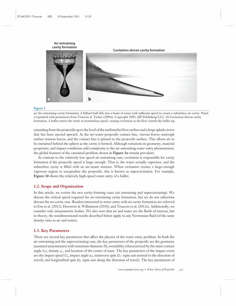
Air-entraining cavity formation is well represented by the canonical vertical water impact ofa sphere, as shown in Figure 1a. The phenomenon is typified by an hourglass-shaped air cavity
CAVITY FORMATION DUE TO THE LEIDENFROST EFFECT
Vakarelski et al. (2011) showed that cavities can also be created by the Leidenfrost effect. A superheated steel sphereforms a robust lubricating layer of water vapor as it passes through a water column. This is a form of low-speedcavitation and is less well studied than the other types of cavity formation in this article.
356 Truscott · Epps · Belden
FL46CH15-Truscott ARI 10 September 2013 15:20
a b
Air-entrainingcavity formation
Cavitation-driven cavity formation
Figure 1(a) Air-entraining cavity formation. A billiard ball falls into a basin of water with sufficient speed to create a subsurface air cavity. Panela reprinted with permission from Truscott & Techet (2009a). Copyright 2009, AIP Publishing LLC. (b) Cavitation-driven cavityformation. A bullet enters the water at tremendous speed, causing cavitation as the flow rounds the bullet tip.
extending from the projectile up to the level of the undisturbed free surface and a large splash crownthat has been ejected upward. At the air-water-projectile contact line, viscous forces outweighsurface tension forces, and the contact line is pinned to the projectile surface. This allows air tobe entrained behind the sphere as the cavity is formed. Although variations in geometry, materialproperties, and impact conditions add complexity to the air-entraining water entry phenomenon,the global features of the canonical problem shown in Figure 1a remain prevalent.
In contrast to the relatively low-speed air-entraining case, cavitation is responsible for cavityformation if the projectile speed is large enough. That is, the water actually vaporizes, and thesubsurface cavity is filled with an air-steam mixture. When cavitation creates a large-enoughvaporous region to encapsulate the projectile, this is known as supercavitation. For example,Figure 1b shows the relatively high-speed water entry of a bullet.
1.2. Scope and Organization
In this article, we review the two cavity-forming cases (air entraining and supercavitating). Wediscuss the critical speed required for air-entraining cavity formation, but we do not otherwisediscuss the no-cavity case. Readers interested in water entry with no cavity formation are referredto Ern et al. (2012), Horowitz & Williamson (2010), and Truscott et al. (2012a). Additionally, weconsider only axisymmetric bodies. We also note that air and water are the fluids of interest, butin theory, the nondimensional results described below apply to any Newtonian fluid (of the samedensity ratio as air and water).
1.3. Key Parameters
There are several key parameters that affect the physics of the water entry problem. In both theair-entraining and the supercavitating case, the key parameters of the projectile are the geometry(assumed axisymmetric with maximum diameter D), wettability (characterized by the static contactangle θ0), density ρs , and location of the center of mass. The key parameters of the impact eventare the impact speed U0, impact angle α0, transverse spin �T (spin axis normal to the direction oftravel), and longitudinal spin �L (spin axis along the direction of travel). The key parameters of
www.annualreviews.org • Water Entry of Projectiles 357
FL46CH15-Truscott ARI 10 September 2013 15:20
Capillary number:viscous force dividedby the surface tensionforce; Ca = μU0/γ
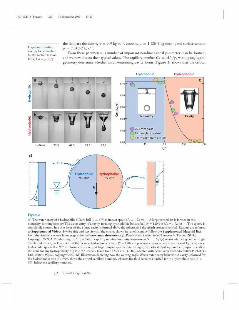
the fluid are the density ρ = 999 kg m−3, viscosity μ = 1.12E-3 kg (ms)−1, and surface tensionγ = 7.34E-2 kg s−2.
From these parameters, a number of important nondimensional parameters can be formed,and we now discuss their typical values. The capillary number Ca ≡ μU0/γ , wetting angle, andgeometry determine whether an air-entraining cavity forms. Figure 2c shows that the critical
t = 0 ms 22.5 47.5 72.5 97.5
U
Hydrophilic
Hy
dro
ph
ilic
Hy
dro
ph
ob
ic
Hydrophobic
θ > 90ºθ < 90º
a
b
d
θ
θ
yyNo cavitNo No cavitytyyo co tN it
25.4 mm g5.4 4 mmmm g..255 gg5 4 mm glas522 ass25
lass or steelasss oor r sttee15 mm g115 5 mmmm gglass or stg15 mm glass or s
tenum or steeoorr sm omnumnmm7 mm alum7 m ammmmmm77 ooum tinum or s
No cavity CavityCa (μ
U0
/γ)
θa (°)
0.10
0.08
0.06
0.04
0.02
0.080 45 90 135 180
Hydrophilic Hydrophobic
c
25.4 mm glass
15 mm glass or steel
7 mm aluminum or steel
Figure 2(a) The water entry of a hydrophilic billiard ball (θ = 67◦) at impact speed U0 = 1.72 ms−1. A large vertical jet is formed in thisnoncavity-forming case. (b) The water entry of a cavity-forming hydrophobic billiard ball (θ = 120◦) at U0 = 1.72 ms−1. The sphere iscompletely encased in a thin layer of air, a large cavity is formed above the sphere, and the splash crown is vertical. Readers are referredto Supplemental Videos 1–4 for side and top views of the entries shown in panels a and b (follow the Supplemental Material linkfrom the Annual Reviews home page at http://www.annualreviews.org). Panels a and b taken from Truscott & Techet (2009a).Copyright 2009, AIP Publishing LLC. (c) Critical capillary number for cavity formation (Ca = μU0/γ ) versus advancing contact angleθ (referred to as θa in Duez et al. 2007). A superhydrophobic sphere (θ = 180) will produce a cavity at any impact speed U0, whereas ahydrophilic sphere θ < 90◦ will form a cavity only at larger impact speeds. Interestingly, the critical capillary number (impact speed) isthe same for any hydrophilicity 0 ≤ θ < 90◦. Panel c taken from Duez et al. (2007), adapted with permission from Macmillan PublishersLtd.: Nature Physics, copyright 2007. (d ) Illustration depicting how the wetting angle affects water entry behavior. A cavity is formed forthe hydrophobic case (θ > 90◦, above the critical capillary number), whereas the fluid remains attached for the hydrophilic case (θ <
90◦, below the capillary number).
358 Truscott · Epps · Belden
FL46CH15-Truscott ARI 10 September 2013 15:20
Bond number:gravitational forcedivided by the surfacetension force;Bo = ρg D2/γ
Weber number:inertia force divided bythe surface tensionforce; We = ρU2
0 D/γ
Froude number:inertia force divided bythe gravitational force;Fr = U0/
√g D
Reynolds number:inertia force divided bythe viscous force;Re = ρU0 D/μ
Spin parameter: tipspeed divided by theforward speed;S = � (D/2) /U0
Mass ratio: projectiledensity divided by thefluid density;m∗ = ρs /ρ
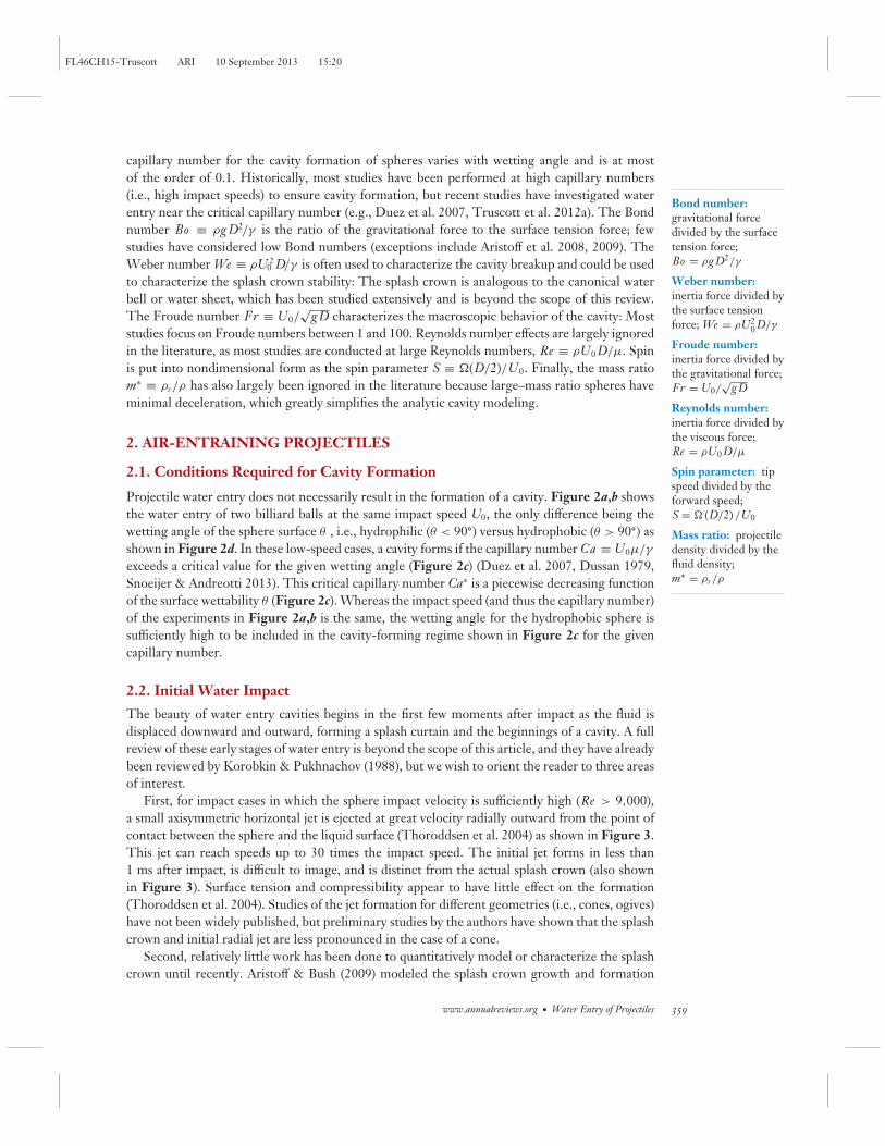
capillary number for the cavity formation of spheres varies with wetting angle and is at mostof the order of 0.1. Historically, most studies have been performed at high capillary numbers(i.e., high impact speeds) to ensure cavity formation, but recent studies have investigated waterentry near the critical capillary number (e.g., Duez et al. 2007, Truscott et al. 2012a). The Bondnumber Bo ≡ ρg D2/γ is the ratio of the gravitational force to the surface tension force; fewstudies have considered low Bond numbers (exceptions include Aristoff et al. 2008, 2009). TheWeber number We ≡ ρU0
2 D/γ is often used to characterize the cavity breakup and could be usedto characterize the splash crown stability: The splash crown is analogous to the canonical waterbell or water sheet, which has been studied extensively and is beyond the scope of this review.The Froude number Fr ≡ U0/
√g D characterizes the macroscopic behavior of the cavity: Most
studies focus on Froude numbers between 1 and 100. Reynolds number effects are largely ignoredin the literature, as most studies are conducted at large Reynolds numbers, Re ≡ ρU0 D/μ. Spinis put into nondimensional form as the spin parameter S ≡ �(D/2)/U0. Finally, the mass ratiom∗ ≡ ρs /ρ has also largely been ignored in the literature because large–mass ratio spheres haveminimal deceleration, which greatly simplifies the analytic cavity modeling.
2. AIR-ENTRAINING PROJECTILES
2.1. Conditions Required for Cavity Formation
Projectile water entry does not necessarily result in the formation of a cavity. Figure 2a,b showsthe water entry of two billiard balls at the same impact speed U0, the only difference being thewetting angle of the sphere surface θ , i.e., hydrophilic (θ < 90◦) versus hydrophobic (θ > 90◦) asshown in Figure 2d. In these low-speed cases, a cavity forms if the capillary number Ca ≡ U0μ/γ
exceeds a critical value for the given wetting angle (Figure 2c) (Duez et al. 2007, Dussan 1979,Snoeijer & Andreotti 2013). This critical capillary number Ca∗ is a piecewise decreasing functionof the surface wettability θ (Figure 2c). Whereas the impact speed (and thus the capillary number)of the experiments in Figure 2a,b is the same, the wetting angle for the hydrophobic sphere issufficiently high to be included in the cavity-forming regime shown in Figure 2c for the givencapillary number.
2.2. Initial Water Impact
The beauty of water entry cavities begins in the first few moments after impact as the fluid isdisplaced downward and outward, forming a splash curtain and the beginnings of a cavity. A fullreview of these early stages of water entry is beyond the scope of this article, and they have alreadybeen reviewed by Korobkin & Pukhnachov (1988), but we wish to orient the reader to three areasof interest.
First, for impact cases in which the sphere impact velocity is sufficiently high (Re > 9,000),a small axisymmetric horizontal jet is ejected at great velocity radially outward from the point ofcontact between the sphere and the liquid surface (Thoroddsen et al. 2004) as shown in Figure 3.This jet can reach speeds up to 30 times the impact speed. The initial jet forms in less than1 ms after impact, is difficult to image, and is distinct from the actual splash crown (also shownin Figure 3). Surface tension and compressibility appear to have little effect on the formation(Thoroddsen et al. 2004). Studies of the jet formation for different geometries (i.e., cones, ogives)have not been widely published, but preliminary studies by the authors have shown that the splashcrown and initial radial jet are less pronounced in the case of a cone.
Second, relatively little work has been done to quantitatively model or characterize the splashcrown until recently. Aristoff & Bush (2009) modeled the splash crown growth and formation
www.annualreviews.org • Water Entry of Projectiles 359
FL46CH15-Truscott ARI 10 September 2013 15:20
Radial jet
Splash crown
Splash domeover
Deep seal
Vertical jets
Surface seal
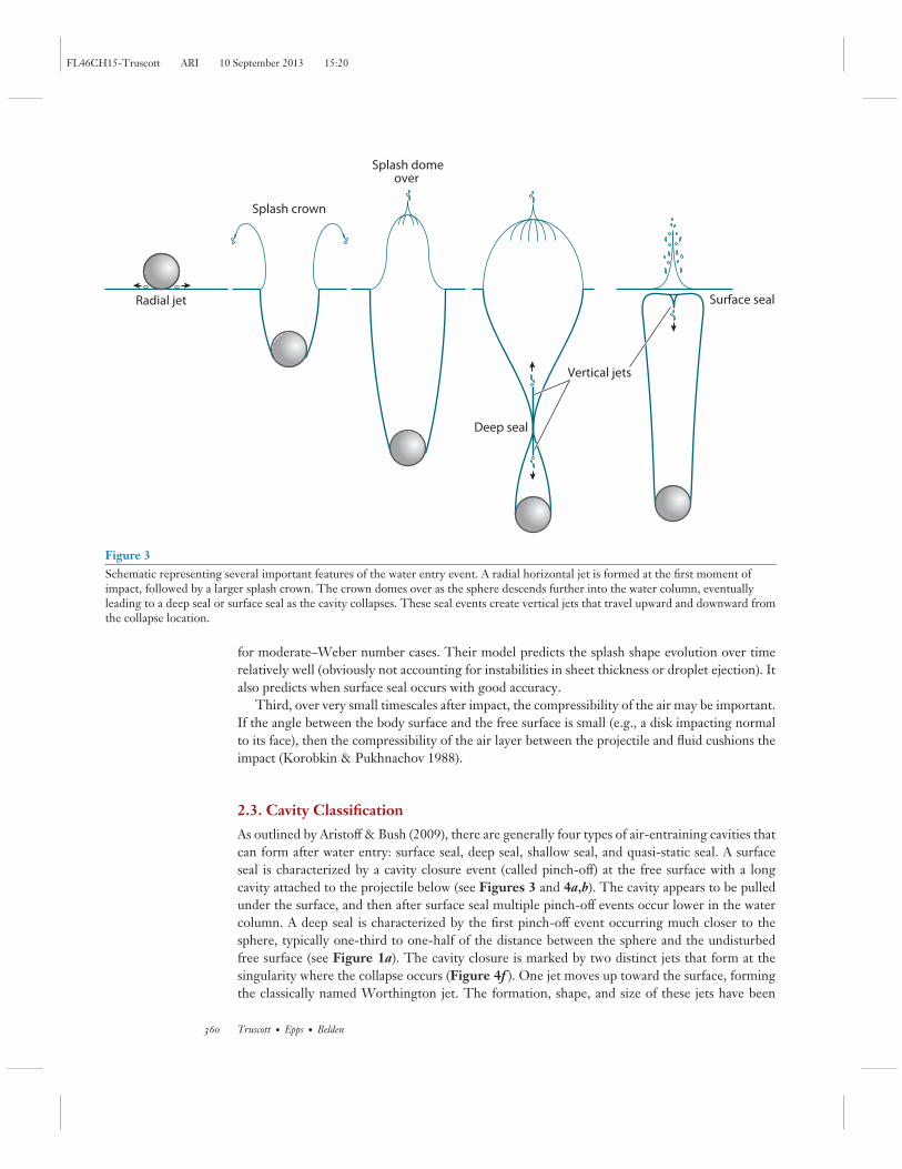
Figure 3Schematic representing several important features of the water entry event. A radial horizontal jet is formed at the first moment ofimpact, followed by a larger splash crown. The crown domes over as the sphere descends further into the water column, eventuallyleading to a deep seal or surface seal as the cavity collapses. These seal events create vertical jets that travel upward and downward fromthe collapse location.
for moderate–Weber number cases. Their model predicts the splash shape evolution over timerelatively well (obviously not accounting for instabilities in sheet thickness or droplet ejection). Italso predicts when surface seal occurs with good accuracy.
Third, over very small timescales after impact, the compressibility of the air may be important.If the angle between the body surface and the free surface is small (e.g., a disk impacting normalto its face), then the compressibility of the air layer between the projectile and fluid cushions theimpact (Korobkin & Pukhnachov 1988).
2.3. Cavity Classification
As outlined by Aristoff & Bush (2009), there are generally four types of air-entraining cavities thatcan form after water entry: surface seal, deep seal, shallow seal, and quasi-static seal. A surfaceseal is characterized by a cavity closure event (called pinch-off) at the free surface with a longcavity attached to the projectile below (see Figures 3 and 4a,b). The cavity appears to be pulledunder the surface, and then after surface seal multiple pinch-off events occur lower in the watercolumn. A deep seal is characterized by the first pinch-off event occurring much closer to thesphere, typically one-third to one-half of the distance between the sphere and the undisturbedfree surface (see Figure 1a). The cavity closure is marked by two distinct jets that form at thesingularity where the collapse occurs (Figure 4f ). One jet moves up toward the surface, formingthe classically named Worthington jet. The formation, shape, and size of these jets have been
360 Truscott · Epps · Belden
FL46CH15-Truscott ARI 10 September 2013 15:20
a b d f
e
c
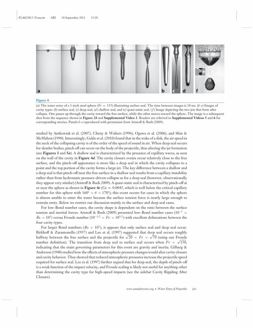
Figure 4(a) The water entry of a 1-inch steel sphere (Fr = 335) illustrating surface seal. The time between images is 18 ms. (b–e) Images ofcavity types: (b) surface seal, (c) deep seal, (d ) shallow seal, and (e) quasi-static seal. ( f ) Image depicting the two jets that form aftercollapse. One passes up through the cavity toward the free surface, while the other moves toward the sphere. The image is a subsequentshot from the sequence shown in Figure 2b and Supplemental Video 3. Readers are referred to Supplemental Videos 5 and 6 forcorresponding movies. Panels b–e reproduced with permission from Aristoff & Bush (2009).
studied by Antkowiak et al. (2007), Cheny & Walters (1996), Ogawa et al. (2006), and Shin &McMahon (1990). Interestingly, Gekle et al. (2010) found that in the wake of a disk, the air speed inthe neck of the collapsing cavity is of the order of the speed of sound in air. When deep seal occursfor slender bodies, pinch off can occur on the body of the projectile, thus altering the jet formation(see Figures 3 and 5a). A shallow seal is characterized by the presence of capillary waves, as seenon the wall of the cavity in Figure 4d. The cavity closure events occur relatively close to the freesurface, and the pinch-off appearance is more like a deep seal in which the cavity collapses to apoint and the top portion of the cavity forms a large jet. The key difference between a shallow anda deep seal is that pinch-off near the free surface in a shallow seal results from a capillary instabilityrather than from hydrostatic pressure-driven collapse as for a deep seal (however, observationallythey appear very similar) (Aristoff & Bush 2009). A quasi-static seal is characterized by pinch-off ator near the sphere as shown in Figure 4e (Ca = 0.0045, which is well below the critical capillarynumber for this sphere with 160◦ < θ < 170◦); this event occurs for cases in which the sphereis almost unable to enter the water because the surface tension force is nearly large enough torestrain entry. Below we restrict our discussion mainly to the surface and deep seal cases.
For low–Bond number cases, the cavity shape is dependent on the ratio between the surfacetension and inertial forces. Aristoff & Bush (2009) presented low–Bond number cases (10−2 <
Bo < 103) versus Froude number (10−1/2 < Fr < 105/2) with excellent delineations between thefour cavity types.
For larger Bond numbers (Bo > 103), it appears that only surface seal and deep seal occur.Birkhoff & Zarantonello (1957) and Lee et al. (1997) suggested that deep seal occurs roughlyhalfway between the free surface and the projectile for
√20 < Fr <
√70 (using our Froude
number definition). The transition from deep seal to surface seal occurs when Fr >√
150,indicating that the main governing parameters for this event are gravity and inertia. Gilbarg &Anderson (1948) studied how the effects of atmospheric pressure changes would alter cavity closureand cavity behavior. They showed that reduced atmospheric pressures increase the projectile speedrequired for surface seal. Lee et al. (1997) further argued that for deep seal, the depth of pinch-offis a weak function of the impact velocity, and Froude scaling is likely not useful for anything otherthan determining the cavity type for high-speed impacts (see the sidebar Cavity Rippling AfterClosure).
www.annualreviews.org • Water Entry of Projectiles 361
FL46CH15-Truscott ARI 10 September 2013 15:20
CAVITY RIPPLING AFTER CLOSURE
After cavity closure, a portion of the air cavity typically remains attached to the projectiles. Researchers have noticeda ripple effect in the cavity wake (Grumstrup et al. 2007). It is believed that the formation of these ripples is initiatedby the postimpact pinch-off of the cavity. The phenomenon is typical when there is a deep seal followed by a longentrained bubble. The frequency of oscillations increases with increased velocity, and differences in the geometryof the projectiles can alter the ripple shape.
2.4. Cavity Shape
Most studies in recent years have focused on deep seal cases. They often determine the depth andtime to pinch-off for varying projectile types. Glasheen & McMahon (1996) proposed a singlevalue of dimensionless pinch-off time, τ = t
√2g/D. Data obtained from Truscott & Techet
(2009b) yielded τ = 1.726±0.0688 (mean ± standard deviation, for 118 trials). This is similar tothe value of 1.74 reported by Gilbarg & Anderson (1948) for spheres. Disks also have a constantdimensionless time to pinch-off, but the value is much larger, τ = 2.285 ± 0.0653 (n = 47 trials)(Glasheen & McMahon 1996). Lee et al. (1997) discovered that not only the nondimensional timebut also the location of deep closure are nearly constant and independent of the Froude number(impact velocity) for spheres.
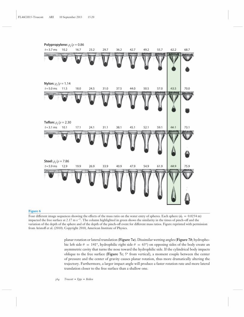
Although most studies assume constant velocity, including Lee et al. (1997), Aristoff et al.(2010) revealed that if the mass ratio is reduced, then the deceleration of the spheres with smallermass ratio can alter the depth of pinch-off, but the nondimensional time to pinch-off—definedin their study as t∗ = tU0/ (D/2)—remains constant. Images of their findings show this dramaticdifference in pinch-off locations but very similar timescales (see Figure 6, which shows fourdifferent mass ratio spheres entering the water at 2.17 m s−1). If m∗ is low enough, the cavityactually collapses on the projectile.
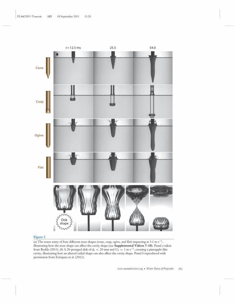
The deep seal cavity shape can also be altered by the geometry of the projectile. Figure 5 showscavity shapes produced by several projectile shapes. For slender bodies, the nose shape can affectwhether the cavity is large enough to surround the entire projectile before pinch-off or produce avery small cavity. Conical noses produce slender cavities; ogival noses produce larger, more opencavities; and flat noses produce cavities similar to disks doming over the most quickly. Cuspednoses (or inverted ogival noses) can produce rather small cavities that wrap up quickly but persistand move along with the tip of the projectile deep into the water (second row in Figure 5a).Altering the radial symmetry can also affect the cavity shape. Figure 5b shows a 20-pronged diskentering the water, making a beautiful cavity similar to the shape of a pineapple (Enriquez et al.2012).
2.5. Asymmetric Cavities
Cavity geometry and subsurface trajectory can be made to deviate from the axisymmetric casespresented above, even when the body is geometrically axisymmetric, by altering the angle ofa body relative to the surface while maintaining a vertical trajectory prior to impact, imposingan asymmetric wetting angle or introducing transverse spin. Figure 7 illustrates these effects inthe case of an acrylic cylinder (L/D = 10) with an ogival nose dropped into quiescent water at3.1 m s−1. When the body enters the water perpendicular to the free surface, it descends without
362 Truscott · Epps · Belden
FL46CH15-Truscott ARI 10 September 2013 15:20
t = 12.5 ms 25.5
Diskshape
54.0
aa
bb
Cone
Cusp
Ogive
Flat
Figure 5(a) The water entry of four different nose shapes (cone, cusp, ogive, and flat) impacting at 3.1 m s−1,illustrating how the nose shape can affect the cavity shape (see Supplemental Videos 7–10). Panel a takenfrom Bodily (2013). (b) A 20-pronged disk of d0 = 20 mm and U0 = 1 m s−1, creating a pineapple-likecavity, illustrating how an altered radial shape can also affect the cavity shape. Panel b reproduced withpermission from Enriquez et al. (2012).
www.annualreviews.org • Water Entry of Projectiles 363
FL46CH15-Truscott ARI 10 September 2013 15:20
t = 3.7 ms 10.2 16.7 23.2 29.7 36.2 42.7 49.2 55.7 62.2 68.7
t = 5.0 ms 11.5 18.0 24.5 31.0 37.5 44.0 50.5 57.0 63.5 70.0
t = 3.1 ms 10.1 17.1 24.1 31.1 38.1 45.1 52.1 59.1 66.1 73.1
t = 5.9 ms 12.9 19.9 26.9 33.9 40.9 47.9 54.9 61.9 68.9 75.9
Polypropylene: ρs/ρ = 0.86
Nylon: ρs/ρ = 1.14
Teflon: ρs/ρ = 2.30
Steel: ρs/ρ = 7.86
63.5
66.1
68.9
Figure 6Four different image sequences showing the effects of the mass ratio on the water entry of spheres. Each sphere (d0 = 0.0254 m)impacted the free surface at 2.17 m s−1. The column highlighted in green shows the similarity in the times of pinch-off and thevariation of the depth of the sphere and of the depth of the pinch-off event for different mass ratios. Figure reprinted with permissionfrom Aristoff et al. (2010). Copyright 2010, American Institute of Physics.
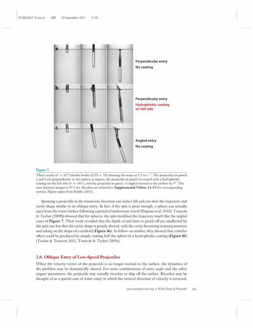
planar rotation or lateral translation (Figure 7a). Dissimilar wetting angles (Figure 7b; hydropho-bic left side θ = 141◦, hydrophilic right side θ = 63◦) on opposing sides of the body create anasymmetric cavity that turns the nose toward the hydrophilic side. If the cylindrical body impactsoblique to the free surface (Figure 7c; 5◦ from vertical), a moment couple between the centerof pressure and the center of gravity causes planar rotation, thus more dramatically altering thetrajectory. Furthermore, a larger impact angle will produce a faster rotation rate and more lateraltranslation closer to the free surface than a shallow one.
364 Truscott · Epps · Belden
FL46CH15-Truscott ARI 10 September 2013 15:20
a
b
c
a
b
c
Perpendicular entry
No coating
Perpendicular entry
Hydrophobic coatingon left side
Angled entry
No coating
Figure 7Three acrylic (θ = 65◦) slender bodies (L/D = 10) entering the water at 3.1 m s−1. The projectiles in panelsa and b are perpendicular to the surface at impact, the projectile in panel b is coated with a hydrophobiccoating on the left side (θ = 141◦), and the projectile in panel c is angled normal to the surface by 5◦. Thetime between images is 47.5 ms. Readers are referred to Supplemental Videos 11–13 for correspondingmovies. Figure taken from Bodily (2013).
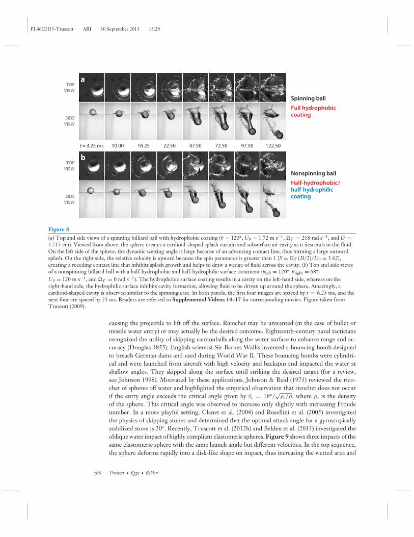
Spinning a projectile in the transverse direction can induce lift and can alter the trajectory andcavity shape similar to an oblique entry. In fact, if the spin is great enough, a sphere can actuallyeject from the water surface following a period of underwater travel (Dupeux et al. 2010). Truscott& Techet (2009b) showed that for spheres, the spin modified the trajectory much like the angledcases of Figure 7. Their work revealed that the depth of and time to pinch-off are unaffected bythe spin rate but that the cavity shape is greatly altered, with the cavity becoming nonaxisymmetricand taking on the shape of a cardioid (Figure 8a). In follow-on studies, they showed that a similareffect could be produced by simply coating half the sphere in a hydrophobic coating (Figure 8b)(Techet & Truscott 2011, Truscott & Techet 2009a).
2.6. Oblique Entry of Low-Speed Projectiles
When the velocity vector of the projectile is no longer normal to the surface, the dynamics ofthe problem may be dramatically altered. For some combinations of entry angle and the otherimpact parameters, the projectile may actually ricochet or skip off the surface. Ricochet may bethought of as a special case of water entry in which the vertical direction of velocity is reversed,
www.annualreviews.org • Water Entry of Projectiles 365
FL46CH15-Truscott ARI 10 September 2013 15:20
a
b
t = 3.25 ms 10.00 16.25 22.50 47.50 72.50 97.50 122.50
TOP
VIEW
SIDE
VIEW
SIDE
VIEW
TOP
VIEW
Spinning ball
Full hydrophobiccoating
Nonspinning ball
Half-hydrophobic/half-hydrophiliccoating
Figure 8(a) Top and side views of a spinning billiard ball with hydrophobic coating (θ = 120◦, U0 = 1.72 m s−1, �T = 218 rad s−1, and D =5.715 cm). Viewed from above, the sphere creates a cardioid-shaped splash curtain and subsurface air cavity as it descends in the fluid.On the left side of the sphere, the dynamic wetting angle is large because of an advancing contact line, thus forming a large outwardsplash. On the right side, the relative velocity is upward because the spin parameter is greater than 1 [S = �T (D/2)/U0 = 3.62],creating a receding contact line that inhibits splash growth and helps to draw a wedge of fluid across the cavity. (b) Top and side viewsof a nonspinning billiard ball with a half-hydrophobic and half-hydrophilic surface treatment (θleft = 120◦, θright = 68◦,U0 = 120 m s−1, and �T = 0 rad s−1). The hydrophobic surface coating results in a cavity on the left-hand side, whereas on theright-hand side, the hydrophilic surface inhibits cavity formation, allowing fluid to be driven up around the sphere. Amazingly, acardioid-shaped cavity is observed similar to the spinning case. In both panels, the first four images are spaced by t = 6.25 ms, and thenext four are spaced by 25 ms. Readers are referred to Supplemental Videos 14–17 for corresponding movies. Figure taken fromTruscott (2009).
causing the projectile to lift off the surface. Ricochet may be unwanted (in the case of bullet ormissile water entry) or may actually be the desired outcome. Eighteenth-century naval tacticiansrecognized the utility of skipping cannonballs along the water surface to enhance range and ac-curacy (Douglas 1855). English scientist Sir Barnes Wallis invented a bouncing bomb designedto breach German dams and used during World War II. These bouncing bombs were cylindri-cal and were launched from aircraft with high velocity and backspin and impacted the water atshallow angles. They skipped along the surface until striking the desired target (for a review,see Johnson 1998). Motivated by these applications, Johnson & Reid (1975) reviewed the rico-chet of spheres off water and highlighted the empirical observation that ricochet does not occurif the entry angle exceeds the critical angle given by θc = 18◦/
√ρs /ρ, where ρ s is the density
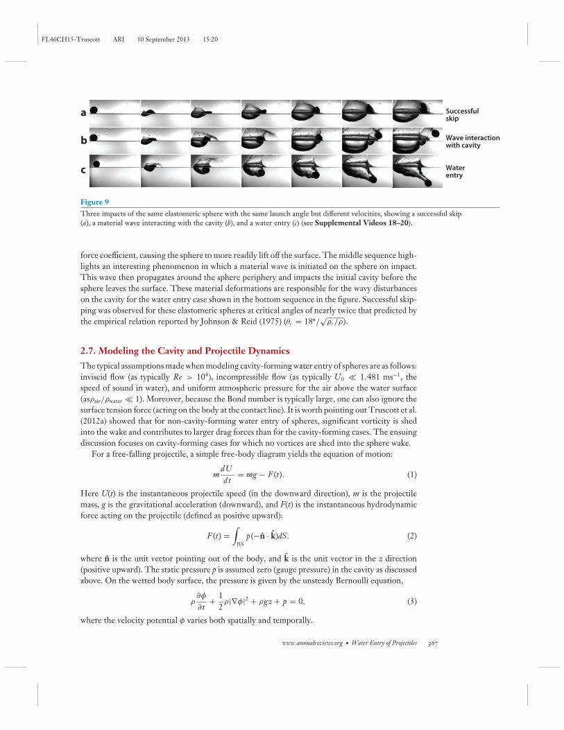
of the sphere. This critical angle was observed to increase only slightly with increasing Froudenumber. In a more playful setting, Clanet et al. (2004) and Rosellini et al. (2005) investigatedthe physics of skipping stones and determined that the optimal attack angle for a gyroscopicallystabilized stone is 20◦. Recently, Truscott et al. (2012b) and Belden et al. (2013) investigated theoblique water impact of highly compliant elastomeric spheres. Figure 9 shows three impacts of thesame elastomeric sphere with the same launch angle but different velocities. In the top sequence,the sphere deforms rapidly into a disk-like shape on impact, thus increasing the wetted area and
366 Truscott · Epps · Belden
FL46CH15-Truscott ARI 10 September 2013 15:20
Successfulskip
Wave interactionwith cavity
Waterentry
a
b
c
Figure 9Three impacts of the same elastomeric sphere with the same launch angle but different velocities, showing a successful skip(a), a material wave interacting with the cavity (b), and a water entry (c) (see Supplemental Videos 18–20).
force coefficient, causing the sphere to more readily lift off the surface. The middle sequence high-lights an interesting phenomenon in which a material wave is initiated on the sphere on impact.This wave then propagates around the sphere periphery and impacts the initial cavity before thesphere leaves the surface. These material deformations are responsible for the wavy disturbanceson the cavity for the water entry case shown in the bottom sequence in the figure. Successful skip-ping was observed for these elastomeric spheres at critical angles of nearly twice that predicted bythe empirical relation reported by Johnson & Reid (1975) (θc = 18◦/
√ρs /ρ).
2.7. Modeling the Cavity and Projectile Dynamics
The typical assumptions made when modeling cavity-forming water entry of spheres are as follows:inviscid flow (as typically Re > 104), incompressible flow (as typically U0 � 1,481 ms−1, thespeed of sound in water), and uniform atmospheric pressure for the air above the water surface(asρair/ρwater � 1). Moreover, because the Bond number is typically large, one can also ignore thesurface tension force (acting on the body at the contact line). It is worth pointing out Truscott et al.(2012a) showed that for non-cavity-forming water entry of spheres, significant vorticity is shedinto the wake and contributes to larger drag forces than for the cavity-forming cases. The ensuingdiscussion focuses on cavity-forming cases for which no vortices are shed into the sphere wake.
For a free-falling projectile, a simple free-body diagram yields the equation of motion:
mdUdt
= mg − F (t). (1)
Here U(t) is the instantaneous projectile speed (in the downward direction), m is the projectilemass, g is the gravitational acceleration (downward), and F(t) is the instantaneous hydrodynamicforce acting on the projectile (defined as positive upward):
F (t) =∫BS
p(−n · k)dS, (2)
where n is the unit vector pointing out of the body, and k is the unit vector in the z direction(positive upward). The static pressure p is assumed zero (gauge pressure) in the cavity as discussedabove. On the wetted body surface, the pressure is given by the unsteady Bernoulli equation,
ρ∂φ
∂t+ 1
2ρ|∇φ|2 + ρgz + p = 0, (3)
where the velocity potential φ varies both spatially and temporally.
www.annualreviews.org • Water Entry of Projectiles 367
FL46CH15-Truscott ARI 10 September 2013 15:20
Epps (2010) verified that Equations 1–3 accurately represent the dynamics of a sphere fallingvertically into the water. Using experimentally measured sphere position and cavity shape data, heimplemented a boundary element method to determine φ for the observed impact event. He thenverified that the hydrodynamic force on the projectile calculated from Equation 2 agreed well withthe hydrodynamic force on the projectile inferred from the experimentally derived accelerationand thus the force from Equation 1.
Of course, to develop a fully predictive dynamic solver, one would need to determine thevelocity potential φ by solving Laplace’s equation with the appropriate boundary conditions:quiescent fluid far from the body, no flow through the body surface, the standard free-surfacekinematic and dynamic conditions, and the initial condition of φ = 0 on the undisturbed freesurface just before impact. For the vertical entry of axisymmetric bodies, Laplace’s equation can besolved in a meridional plane, which greatly simplifies the analysis. Any numerical implementationof this model will do the following at each time step: solve Laplace’s equation, determine thefluid pressure field from the current and past values of φ using Equation 3, integrate the fluidpressure over the body to get the force using Equation 2, determine the acceleration of the bodyusing Equation 1, and update the position of the projectile and free surface. This approach andsimilar potential flow solvers have been implemented numerically by several authors (Abelson1971, Bergmann et al. 2009, Birkhoff & Isaacs 1951, Gaudet 1998, Longuet-Higgins & Cokelet1976, Miloh & Shukron 1991, Yan et al. 2009, Zhao & Faltinsen 1993). Analytical approachesbased on this model have been made as well (e.g., Aristoff & Bush 2009, Duclaux et al. 2007, Leeet al. 1997).
One of two simplifying assumptions is often made in the recent literature. The first is thatof constant speed U(t) = U0, which is valid only in the case of high–mass ratio projectiles (e.g.,steel and tungsten). Alternatively, those that do account for deceleration often assume that theforce on the sphere can be modeled as F (t) = 1
2 ρ [U(t)]2 CD(π D2/4) with a prechosen, constantdrag coefficient CD (e.g., Aristoff et al. 2010). However, Truscott et al. (2012a) showed that forlow–mass ratio spheres, not only is the projectile decelerating, but also the force coefficient isunsteady.
In any model, careful attention must be paid in the treatment of the contact line dynamics;in particular, the location and angle at which the fluid separates from the projectile greatly affectthe resulting cavity shape. Most authors pin the cavity to an experimentally observed point onthe projectile surface (e.g., the equator of a sphere) and set the flow separation angle based onobservations as well. To achieve a fully predictive numerical model of water entry for an arbitrarybody and surface wettability, one must model the contact line dynamics. To our knowledge, thisremains an open research issue.
2.8. Modeling the Dynamics in the First Few Moments of Impact
Much work has also been done to model the impact forces during the initial stages of waterimpact, before the body has submerged more than one-half the diameter. This body of workis distinctly different than the modeling efforts described above, as restricting the analysis tothe first few moments of impact allows one to make additional simplifying assumptions. In thework of von Karman (1929) and many theoretical investigations since, the quadratic pressureterm has been neglected and the unsteady term written in terms of an added mass coefficient.The vertical force is then given as F3 = d (A33V )/dt, where A33 is the added mass coefficient inheave; keeping A33 inside the derivative accounts for the dependence of the amount of the bodyin contact with the fluid on the submergence (and thus time). A major contribution put forthin Wagner’s (1932) theory accounted for the fluid surface in contact with the body rising with
368 Truscott · Epps · Belden
FL46CH15-Truscott ARI 10 September 2013 15:20
respect to the undisturbed free surface; this has been shown to have a significant effect on theresultant force. More advanced mathematical theories and a history of the problem in the yearssince have already been reviewed by Korobkin & Pukhnachov (1988); notable contributions havebeen made by Dobrovolskaya (1969), Miloh (1991), and Faltinsen & Zhao (1997). More recently,Korobkin & Scolan (2006) presented a linearized Wagner approach for several three-dimensionalshapes. Faltinsen & Zhao (1997) compared several theoretical and numerical models of spherewater impact and showed that theories that neglect the quadratic pressure term tend to be valid fordimensionless submergence depths up to U0t/D ≈ 0.2. The inclusion of the quadratic pressureterm in numerical methods led to more accurate force predictions. These results were supported bythe experiments of Moghisi & Squire (1981) in which a force gauge, which was directly attached toa sphere, was used to measure the forces on the sphere during water impact for Reynolds numbersless than 104. Laverty (2004) analyzed the forces on a sphere between initial impact and the timecorresponding to a submergence of one-fourth the diameter from high-speed digital video data(1,500 frames per second) and found good agreement with the generalized Wagner formulationdeveloped by Miloh & Shukron (1991) for Reynolds numbers between 25 and 105. Thus, the rateof change of momentum of the added fluid mass is the dominant contributor to the vertical forcein the initial stages of impact, with the quadratic pressure term becoming important even at smallvalues of body submergence.
3. SUPERCAVITATING PROJECTILES
3.1. Conditions Required for Supercavitation
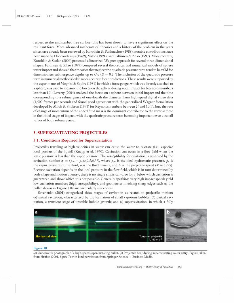
Projectiles traveling at high velocities in water can cause the water to cavitate (i.e., vaporizelocal pockets of the liquid) (Knapp et al. 1970). Cavitation can occur in a flow field when thestatic pressure is less than the vapor pressure. The susceptibility for cavitation is governed by thecavitation number σ = (p∞ − pv)/(0.5ρU 2), where p∞ is the local hydrostatic pressure, pv isthe vapor pressure of the fluid, ρ is the fluid density, and U is the projectile speed (May 1975).Because cavitation depends on the local pressure in the flow field, which is in turn determined bybody shape and motion at entry, there is no single empirical value for σ below which cavitation isguaranteed and above which it is not possible. Generally speaking, very high impact speeds yieldlow cavitation numbers (high susceptibility), and geometries involving sharp edges such as thebullet shown in Figure 10a are particularly susceptible.
Savchenko (2001) categorized three stages of cavitation as related to projectile motion:(a) initial cavitation, characterized by the formation of small vaporous bubbles; (b) partial cav-itation, a transient stage of unstable bubble growth; and (c) supercavitation, in which a fully
ba
Horizontal view Tungsten projectile1,160 m s–1
Figure 10(a) Underwater photograph of a high-speed supercavitating bullet. (b) Projectile bent during supercavitating water entry. Figure takenfrom Hrubes (2001, figure 7) with kind permission from Springer Science + Business Media.
www.annualreviews.org • Water Entry of Projectiles 369
FL46CH15-Truscott ARI 10 September 2013 15:20
developed cavity encapsulates the projectile. Rood (1991) reviewed early developments inthe understanding of cavitation inception, and the underlying physics of cavitation bubblegrowth/collapse was reviewed by Plesset & Prosperetti (1977). The supercavitating regime isstill an intensely studied area, particularly as a potential means of drag reduction (Ashley 2001).A supercavity tends to be very elongated owing to the slender geometry and high speed of theprojectiles. Because only a small portion of the projectile actually contacts the liquid, the vis-cous drag on the projectile is dramatically reduced when riding inside a supercavity. Despite thisinteresting phenomenon, relatively few studies of traveling supercavitating bodies have been pub-lished. Recently, Weiland & Vlachos (2012) investigated the inception and growth of cavitationover cylindrical projectiles entering normal to the water surface at high speed. In one of the firstand best studies of its kind, Hrubes (2001) investigated bullet water entry at speeds faster thanthe speed of sound in water (1,481 m s−1). Figure 10a shows a supercavitating projectile fromthis study. A large body of literature has also been dedicated to the study of artificial (also knownas ventilated) supercavities (Franc & Michel 2004), but we limit our review to naturally formedcavities.
3.2. Modeling the Supercavitation Case
Several theoretical cavity models have been developed. Logvinovich (1972) and Paryshev (2006)developed analytical models for cavity formation and cavity oscillations based partially on empiricaldata and mostly on control volume analysis. Others have focused more on projectile stability(e.g., Savchenko et al. 2000). Hassan (1999) modeled the planing forces on a supercavitatingprojectile. Grady (1979) wrote an entire volume of work on the subject of hydroballistics, whichincludes a excellent summary of both quantitative and qualitative experimental data taken by May(1952, 1975; May & Hoover 1963). More recently, Neaves & Edwards (2006) used a numericalsimulation employing preconditioning to estimate the cavity shape, temperature, shock formation,and pressure inside and outside the cavity of projectile water entry.
3.3. Water Entry of High-Speed Projectiles
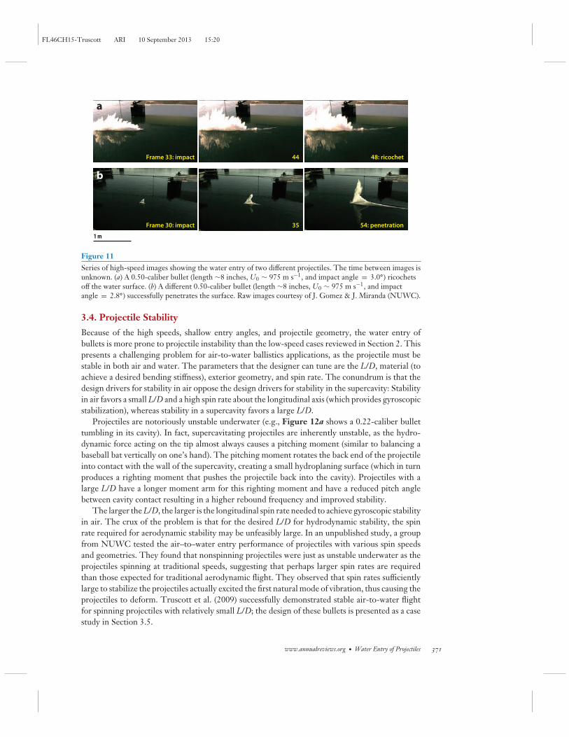
An extension of the research presented in Section 2.6 is the high-speed, oblique water entryof projectiles such as military ballistics. Projectiles that impact the water at shallow angles aremore prone to ricochet. If they do pierce the surface, they often break up or tumble owing toinstabilities (see Figure 11). An understanding of the oblique water entry of high-speed ballisticsis important for improving defensive weapon technology, yet the published research is scarce.Several experimental studies have looked at the vertical air-water impact of high-speed projectiles(e.g., Gilbarg & Anderson 1948, May 1952, Shi et al. 2000, Weiland & Vlachos 2012). Full-scale,shallow-angle, air-to-water studies have been performed by different research groups at severallaboratories around the world, but none has been formally published to date.
Unpublished results from tests performed by a group at the Naval Undersea Warfare Center(NUWC) in Newport, Rhode Island, revealed that projectiles with flat noses, tapered tips, andhigh length-to-diameter ratios (L/D) can pierce the surface at shallow angles and continue todescend through the water column without ricochet (Gomez & Shukla 2001, Hrubes 2001) (seeFigure 10). The experiments revealed that these types of projectiles are stabilized underwaterthrough the hydrodynamic planing of the rear portion of the projectile against the cavity side walls(Hrubes 2001). Stability was observed to be highly sensitive to the bullet and cavity geometry,with catastrophic destabilization leading to a tungsten bullet bending beyond its yield strength(see Figure 10b).
370 Truscott · Epps · Belden
FL46CH15-Truscott ARI 10 September 2013 15:20
1 m
Frame 33: impact 44 48: ricochet
Frame 30: impact 35 54: penetration
a
b
Figure 11Series of high-speed images showing the water entry of two different projectiles. The time between images isunknown. (a) A 0.50-caliber bullet (length ∼8 inches, U0 ∼ 975 m s−1, and impact angle = 3.0◦) ricochetsoff the water surface. (b) A different 0.50-caliber bullet (length ∼8 inches, U0 ∼ 975 m s−1, and impactangle = 2.8◦) successfully penetrates the surface. Raw images courtesy of J. Gomez & J. Miranda (NUWC).
3.4. Projectile Stability
Because of the high speeds, shallow entry angles, and projectile geometry, the water entry ofbullets is more prone to projectile instability than the low-speed cases reviewed in Section 2. Thispresents a challenging problem for air-to-water ballistics applications, as the projectile must bestable in both air and water. The parameters that the designer can tune are the L/D, material (toachieve a desired bending stiffness), exterior geometry, and spin rate. The conundrum is that thedesign drivers for stability in air oppose the design drivers for stability in the supercavity: Stabilityin air favors a small L/D and a high spin rate about the longitudinal axis (which provides gyroscopicstabilization), whereas stability in a supercavity favors a large L/D.
Projectiles are notoriously unstable underwater (e.g., Figure 12a shows a 0.22-caliber bullettumbling in its cavity). In fact, supercavitating projectiles are inherently unstable, as the hydro-dynamic force acting on the tip almost always causes a pitching moment (similar to balancing abaseball bat vertically on one’s hand). The pitching moment rotates the back end of the projectileinto contact with the wall of the supercavity, creating a small hydroplaning surface (which in turnproduces a righting moment that pushes the projectile back into the cavity). Projectiles with alarge L/D have a longer moment arm for this righting moment and have a reduced pitch anglebetween cavity contact resulting in a higher rebound frequency and improved stability.
The larger the L/D, the larger is the longitudinal spin rate needed to achieve gyroscopic stabilityin air. The crux of the problem is that for the desired L/D for hydrodynamic stability, the spinrate required for aerodynamic stability may be unfeasibly large. In an unpublished study, a groupfrom NUWC tested the air–to–water entry performance of projectiles with various spin speedsand geometries. They found that nonspinning projectiles were just as unstable underwater as theprojectiles spinning at traditional speeds, suggesting that perhaps larger spin rates are requiredthan those expected for traditional aerodynamic flight. They observed that spin rates sufficientlylarge to stabilize the projectiles actually excited the first natural mode of vibration, thus causing theprojectiles to deform. Truscott et al. (2009) successfully demonstrated stable air-to-water flightfor spinning projectiles with relatively small L/D; the design of these bullets is presented as a casestudy in Section 3.5.
www.annualreviews.org • Water Entry of Projectiles 371
FL46CH15-Truscott ARI 10 September 2013 15:20
Standard bullet Modified bullet
t = 2.4 ms t = 2.4 ms
t = 2.4 ms
θ = 8.0°
v = 102.2 m s–1
Bullet
Casing
Neck
Primer
Standard bullet Modified bullet(with tapered tip)
Foot
ShoulderExperimental
TheoreticalProjectile
Tip0.10
0.08
0.06
0.04
0.02
0
0 0.05 0.10 0.15 0.20 0.25 0.30
m
m
–0.02
–0.04
–0.06
–0.08
–0.10
Runout
Rim
ba
c d
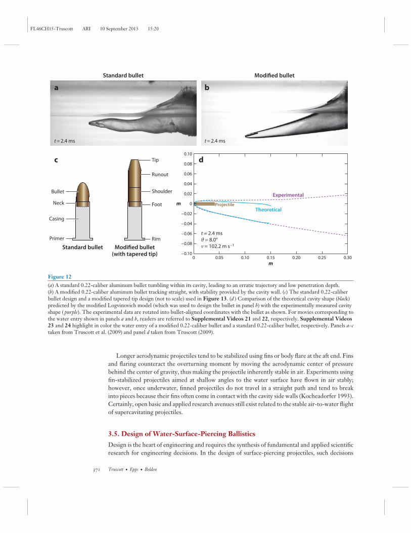
Figure 12(a) A standard 0.22-caliber aluminum bullet tumbling within its cavity, leading to an erratic trajectory and low penetration depth.(b) A modified 0.22-caliber aluminum bullet tracking straight, with stability provided by the cavity wall. (c) The standard 0.22-caliberbullet design and a modified tapered tip design (not to scale) used in Figure 13. (d ) Comparison of the theoretical cavity shape (black)predicted by the modified Logvinovich model (which was used to design the bullet in panel b) with the experimentally measured cavityshape ( purple). The experimental data are rotated into bullet-aligned coordinates with the bullet as shown. For movies corresponding tothe water entry shown in panels a and b, readers are referred to Supplemental Videos 21 and 22, respectively. Supplemental Videos23 and 24 highlight in color the water entry of a modified 0.22-caliber bullet and a standard 0.22-caliber bullet, respectively. Panels a–ctaken from Truscott et al. (2009) and panel d taken from Truscott (2009).
Longer aerodynamic projectiles tend to be stabilized using fins or body flare at the aft end. Finsand flaring counteract the overturning moment by moving the aerodynamic center of pressurebehind the center of gravity, thus making the projectile inherently stable in air. Experiments usingfin-stabilized projectiles aimed at shallow angles to the water surface have flown in air stably;however, once underwater, finned projectiles do not travel in a straight path and tend to breakinto pieces because their fins often come in contact with the cavity side walls (Kocheadorfer 1993).Certainly, open basic and applied research avenues still exist related to the stable air-to-water flightof supercavitating projectiles.
3.5. Design of Water-Surface-Piercing Ballistics
Design is the heart of engineering and requires the synthesis of fundamental and applied scientificresearch for engineering decisions. In the design of surface-piercing projectiles, such decisions
372 Truscott · Epps · Belden
FL46CH15-Truscott ARI 10 September 2013 15:20
include the geometry, speed, and angle of impact. Most bullets break up or ricochet because theyare designed for air not water (Figure 12a). For axisymmetric (cylindrical) bullets, the geometryis fully defined by the diameter as a function of distance from the tip to tail, D(x). A typicalsupercavitating projectile will have a flat tip with nonzero diameter D (0) > 0. The design ofthe geometry [i.e., determining D(x)] can be carried out using the theory of Logvinovich (1972)and Hassan (1999), which was improved by Truscott (2009). They determined the desired speed,spin rate, angle of incidence, and tip diameter for straight and level flight of a bullet travelingunderwater. The resulting cavity shape is illustrated in Figure 12d. The bullet diameter D(x)is then determined to fit within the package space afforded by the cavity. The bullet shown
t= 0 ms 0.6
0.1 0.7
0.2 0.8
0.3 0.9
0.4 1.0
0.5 1.1
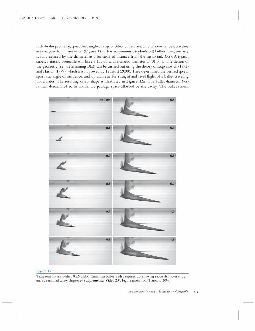
Figure 13Time series of a modified 0.22-caliber aluminum bullet (with a tapered tip) showing successful water entryand streamlined cavity shape (see Supplemental Video 25). Figure taken from Truscott (2009).
www.annualreviews.org • Water Entry of Projectiles 373
FL46CH15-Truscott ARI 10 September 2013 15:20
in Figure 12d is a simple cylinder, which fits within the cavity. The total runout (i.e., lengthbetween the shoulder and chamber, as shown in Figure 12c) of the bullet is chosen to achievethe desired projectile mass (e.g., 40 grains) and refitted into the projectile housing (Figure 12c).Experimental data proved that this design process works, as seen in the relatively straight flightof Figure 12b and the good agreement between the experimental cavity and theoretical one inFigure 12d. When properly designed using a combination of modeling and empirical informa-tion, supercavitating projectiles can create cavities just the right size and travel long distancesunderwater. Figure 13 shows the water entry and downstream run of a modified 0.22-caliberbullet with a smaller tapered nose than that of Figure 12d. Stabilization through contact withthe inside of the cavity wall is apparent at t = 0.5 ms (Truscott 2009, Truscott et al. 2009).
SUMMARY POINTS
1. Two physical processes are responsible for cavity formation: the deformation of the freesurface in the low-speed air-entraining cases and cavitation in the high-speed supercav-itating cases.
2. Air-entraining cavity formation occurs when the capillary number exceeds a critical value,which is a function of the wettability of the surface.
3. Asymmetric cavity shapes can be created by geometric asymmetry, transverse spin, ormanipulation of the surface wettability.
4. Because typical water entry problems occur at very high Reynolds numbers, both thecavity dynamics and projectile dynamics can be successfully modeled using potentialflow theory.
5. Cavitation susceptibility depends on body geometry and the cavitation number.
6. Supercavitating bullets (with large L/D) are often stabilized in air by fins or flaring butnot by spin. In water, they are stabilized by leaning against the cavity wall.
7. Research regarding supercavitating cavity dynamics has informed the design of high-speed surface-piercing ballistics.
FUTURE ISSUES
1. The modeling of the contact line dynamics in the air-entraining case should be improvedthrough the synthesis of the macroscopic results presented above with the microscopicresults of Snoeijer & Andreotti (2013). This will enable a fully predictive dynamic modelof air-entraining projectile water entry for arbitrary body geometry and impact velocity.
2. Experimental and theoretical work needs to be performed to investigate the dynamicsof the surface seal cavity case (e.g., cavity shape, trajectory, and forces versus Fr, Re, andm∗).
3. The influence of cavitation should be determined: How does the introduction of watervapor into the cavity affect its development and evolution?
4. High-fidelity measurements of projectile acceleration, projectile surface stresses, contactline position, and cavity pressure using projectile-mounted sensors need to be acquired.
374 Truscott · Epps · Belden
FL46CH15-Truscott ARI 10 September 2013 15:20
DISCLOSURE STATEMENT
The authors are not aware of any biases that might be perceived as affecting the objectivity ofthis review.
ACKNOWLEDGMENTS
We would like to thank the ONR ULI (University Laboratory Initiative), grant N00014-06-1-0445 by Theresa McMullen (ONR code 333), for providing thesis support for T.T.T. and the ULI,grant N000141110872 from Maria Medeiros. We are grateful to the Naval Research EnterpriseInternship Program (NREIP) and Dr. David Beal, Dr. Jason Gomez, Dr. Robert Kuklinski, andJoseph Miranda at the Naval Undersea Warfare Center (NUWC) for the opportunity to work forseveral summers on this research in Rhode Island. We acknowledge the Massachusetts Instituteof Technology and the Department of Mechanical and Ocean Engineering at MIT as well asAlexandra Techet for their support both in and outside the laboratory. We also thank the BrighamYoung University Department of Mechanical Engineering and the Thayer School of Engineeringat Dartmouth College for providing high-speed cameras, space, and support. Finally, J.B. thanksthe NUWC In-house Laboratory Independent Research (ILIR) for funding support (monitoredby Drs. Tony Ruffa and Neil Dubois).
LITERATURE CITED
Abelson HI. 1970. Pressure measurements in the water-entry cavity. J. Fluid Mech. 44:129–44Abelson HI. 1971. A prediction of water-entry cavity shapes. Trans. ASME D 93:501–4Antkowiak A, Bremond N, Le Dizes S, Villermaux E. 2007. Short-term dynamics of a density interface
following an impact. J. Fluid Mech. 577:241–50Aristoff J, Bush J. 2009. Water entry of small hydrophobic spheres. J. Fluid Mech. 619:45–78Aristoff JM, Truscott TT, Techet AH, Bush JWM. 2008. The water-entry cavity formed by low Bond number
impacts. Phys. Fluids 20:091111Aristoff JM, Truscott TT, Techet AH, Bush JWM. 2010. The water entry of decelerating spheres. Phys. Fluids
22:032102Ashley S. 2001. Warp drive underwater. Sci. Am. 284:70–79Belden J, Jandron MA, Truscott TT. 2013. Physics of elastic spheres skipping on water. In On the Physics of
Sports, ed. C Clanet. Paris: Ed. l’Ecole Polytech.Bell GE. 1924. On the impact of a solid sphere with a fluid surface. Philos. Mag. 48:753–64Bergmann R, van der Meer D, Gekle S, van der Bos A, Lohse D. 2009. Controlled impact of a disk on a water
surface: cavity dynamics. J. Fluid Mech. 381–409Birkhoff G, Isaacs R. 1951. Transient cavities in air-water entry. Nav. Ordnance Rep. 1490, White Oak, MDBirkhoff G, Zarantonello EH. 1957. Jets, Wakes, and Cavities. Appl. Math. Mech. New York: Academic. 353 pp.Bodily KG. 2013. The water entry of slender axisymmetric bodies: forces, trajectories and acoustics. MS thesis. Brigham
Young Univ., Provo, UTCheny J, Walters K. 1996. Extravagant viscoelastic effects in the Worthington jet experiment. J. Non-Newton.
Fluid Mech. 67:125–35Clanet C, Hersen F, Bocquet L. 2004. Secrets of successful stone skipping. Nature 427:29Dobrovolskaya Z. 1969. On some problems of similarity flow of fluid with a free surface. J. Fluid Mech.
36:805–29Douglas H. 1855. A Treatise on Naval Gunnery. London: Conway Marit. 4th ed.Duclaux V, Caille F, Duez C, Ybert C, Bocquet L, Clanet C. 2007. Dynamics of transient cavities. J. Fluid
Mech. 591:1–19Duez C, Ybert C, Clanet C, Bocquet L. 2007. Making a splash with water repellency. Nat. Phys. 3:180–83Dupeux G, Goff AL, Quere D, Clanet C. 2010. The spinning ball spiral. New J. Phys. 12:093004
www.annualreviews.org • Water Entry of Projectiles 375
FL46CH15-Truscott ARI 10 September 2013 15:20
Dussan EB V. 1979. On the spreading of liquids on solid surfaces: static and dynamic contact lines. Annu. Rev.Fluid Mech. 11:371–400
Enriquez OR, Peters IR, Gekle S, Schmidt LE, Lohse D, van der Meer D. 2012. Collapse and pinch-off of anon-axisymmetric impact-created air cavity in water. J. Fluid Mech. 701:40–58
Epps BP. 2010. An impulse framework for hydrodynamic force analysis: fish propulsion, water entry of spheres, andmarine propellers. PhD thesis. Mass. Inst. Technol., Cambridge, MA
Ern P, Risso F, Fabre D, Magnaudet J. 2012. Wake-induced oscillatory paths of bodies freely rising or fallingin fluids. Annu. Rev. Fluid Mech. 44:97–121
Faltinsen OM, Zhao R. 1997. Water entry of ship sections and axisymmetric bodies. Proc. AGARD R-827FDP Ukr. Inst. Hydromech. Workshop High-Speed Body Motion Water, ed. B Cantwell, Art. 24–1. Neuillysur Seine, Fr.: AGARD
Franc JP, Michel JM. 2004. Fundamentals of Cavitation. New York: SpringerGaudet S. 1998. Numerical simulation of circular disks entering the free surface of a fluid. Phys. Fluids 10:2489–
99Gekle S, Peters IR, Gordillo JM, van der Meer D, Lohse D. 2010. Supersonic air flow due to solid-liquid
impact. Phys. Rev. Lett. 104:024501Gilbarg D, Anderson RA. 1948. Influence of atmospheric pressure on the phenomena accompanying the entry
of spheres into water. J. Appl. Phys. 19:127–39Glasheen JW, McMahon TA. 1996. Vertical water entry of disks at low Froude numbers. Phys. Fluids 8:2078–
83Gomez JT, Shukla A. 2001. Multiple impact penetration of semi-infinite concrete. Int. J. Impact Eng. 25:965–
79Grady RJ. 1979. Hydroballistics Design Handbook, Vol. 1. Washington, DC: Nav. Sea Syst. Command
Hydromech. Comm.Grumstrup T, Keller JB, Belmonte A. 2007. Cavity ripples observed during the impact of solid objects into
liquids. Phys. Rev. Lett. 99:114502Hassan SE. 1999. Analysis of hydrodynamic planing forces associated with cavity-riding vehicles. Tech. Memo.
990085, Nav. Undersea Warf. Cent., Newport, RIHorowitz M, Williamson CHK. 2010. The effect of Reynolds number on the dynamics and wakes of freely
rising and falling spheres. J. Fluid Mech. 651:251–94Hrubes JD. 2001. High-speed imaging of supercavitating underwater projectiles. Exp. Fluids 30:57–64Johnson W. 1998. The ricochet of spinning and non-spinning projectiles, mainly from water. Part II: an
outline of the theory and warlike applications. Int. J. Impact Eng. 21:25–34Johnson W, Reid SR. 1975. Ricochet of spheres off water. J. Mech. Eng. Sci. 17:71–81Knapp R, Daily J, Hammitt F. 1970. Cavitation. New York: McGraw-HillKocheadorfer P. 1993. Low cost free flight development testing of a rocket propelled high speed underwater missile.
Final Rep. 02841-5047, Nav. Undersea Warf. Cent., Newport, RIKorobkin AA, Pukhnachov VV. 1988. Initial stage of water impact. Annu. Rev. Fluid Mech. 20:159–85Korobkin AA, Scolan YM. 2006. Three-dimensional theory of water impact. Part 2. Linearized Wagner
problem. J. Fluid Mech. 549:343–73Laverty SM. 2004. Experimental hydrodynamics of spherical projectiles impacting on a free surface using high speed
imaging techniques. Master’s thesis. Mass. Inst. Technol., Cambridge, MALee M, Longoria RG, Wilson DE. 1997. Cavity dynamics in high-speed water entry. Phys. Fluids 9:540–50Logvinovich GV. 1972. Hydrodynamics of Free-Boundary Flows. NASA TT F-658. Jerusalem/Springfield, VA:
Israel Prog. Sci. Transl. US Dep. Commerce, Natl. Tech. Inf. Serv.Longuet-Higgins MS, Cokelet ED. 1976. The deformation of steep surface waves on water. I. A numerical
method of computation.Proc. R. Soc. Lond. A 350:1–26May A. 1951. Effect of surface condition of a sphere on its water-entry cavity. J. Appl. Phys. 22:1219–22May A. 1952. Vertical entry of missiles into water. J. Appl. Phys. 23:1362–72May A. 1975. Water entry and the cavity-running behavior of missiles. Tech. Rep. 20910, Nav. Surf. Weapons
Cent., White Oak Lab., MDMay A, Hoover WR. 1963. A study of the water-entry cavity. Unclassif. NOLTR 63-264, US Nav. Ordnance
Lab., White Oak, MD
376 Truscott · Epps · Belden
FL46CH15-Truscott ARI 10 September 2013 15:20
May A, Woodhull JC. 1948. Drag coefficients of steel spheres entering water vertically. J. Appl. Phys. 19:1109–21
May A, Woodhull JC. 1950. The virtual mass of a sphere entering water vertically. J. Appl. Phys. 21:1285–89
Miloh T. 1991. On the initial-stage slamming of a rigid sphere in a vertical water entry. Appl. Ocean Res.13:43–48
Miloh T, Shukron Y. 1991. Ricochet off water of spherical projectiles. J. Ship Res. 35:91–100Moghisi M, Squire PT. 1981. An experimental investigation of the initial force of impact on a sphere striking
a liquid surface. J. Fluid Mech. 108:133–46Neaves MD, Edwards JR. 2006. All-speed time-accurate underwater projectile calculations using a precondi-
tioning algorithm. J. Fluids Eng. 128:284–96Ogawa A, Utsuno K, Mutou M, Kouzen S, Shimotake Y, Satou Y. 2006. Morphological study of cavity
and Worthington jet formations for Newtonian and non-Newtonian liquids. Part. Sci. Technol. 24:181–225
Paryshev EV. 2006. Approximate mathematical models in high-speed hydrodynamics. J. Eng. Math. 55:41–64
Plesset MS, Prosperetti A. 1977. Bubble dynamics and cavitation. Annu. Rev. Fluid Mech. 9:145–85Richardson EG. 1948. The impact of a solid on a liquid surface. Proc. Phys. Soc. 4:352–67Rood EP. 1991. Review: mechanisms of cavitation inception. J. Fluids Eng. 113:163–75Rosellini L, Hersen F, Clanet C, Bocquet L. 2005. Skipping stones. J. Fluid Mech. 543:137–46Savchenko Y. 2001. Supercavitation: problems and perspectives. Presented at CAV 2001, Int. Symp. Cavitation,
4th, Pasadena, CASavchenko Y, Semenenko V, Putilin S, Savchenko V, Naumova Y. 2000. Theory of stable model motion with venti-
lated and unventilated supercavities. Rep., Dep. Free Bound. Flows, Natl. Acad. Sci. Ukr. Inst. Hydromech.,Kyiv
Seddon C, Moatamedi M. 2006. Review of water entry with applications to aerospace structures. Int. J. ImpactEng. 32:1045–67
Shi HH, Itoh M, Takami T. 2000. Optical observation of the supercavitation induced by high-speed waterentry. J. Fluids Eng. 122:806–10
Shin J, McMahon TA. 1990. The tuning of a splash. Phys. Fluids 2:1312–17Snoeijer JH, Andreotti B. 2013. Moving contact lines: scales, regimes, and dynamical transitions. Annu. Rev.
Fluid Mech. 45:269–92Techet A, Truscott T. 2011. Water entry of spinning hydrophobic and hydrophilic spheres. J. Fluids Struct.
27:716–26Thoroddsen ST, Etoh TG, Takehara K, Takano Y. 2004. Impact jetting by a solid sphere. J. Fluid Mech.
499:139–48Truscott TT. 2009. Cavity dynamics of water entry for spheres and ballistic projectiles. PhD diss. Mass. Inst.
Technol., Cambridge, MATruscott TT, Beal DN, Techet AH. 2009. Shallow angle water entry of ballistic projectiles. Proc. Cav2009
Int. Symp. Cavitation, ed. S Ceccio, Art. 100Truscott TT, Epps BP, Techet AH. 2012a. Unsteady forces on spheres during free-surface water entry.
J. Fluid Mech. 704:173–210Truscott TT, Techet AH. 2009a. A spin on cavity formation during water entry of hydrophobic and hydrophilic
spheres. Phys. Fluids 21:121703Truscott TT, Techet AH. 2009b. Water entry of spinning spheres. J. Fluid Mech. 625:135–65Truscott TT, Wright MM, Langley KR, Belden J. 2012b. Holy balls! Balls that walk on water. Phys. Fluids
24:091103Vakarelski IU, Marston JO, Chan DYC, Thoroddsen ST. 2011. Drag reduction by Leidenfrost vapor layers.
Phys. Rev. Lett. 106:214501von Karman T. 1929. The impact on seaplane floats during landing. Tech. Note 321, Natl. Advis. Comm.
Aeronaut., Washington, DCWagner H. 1932. Phenomena associated with impacts and sliding on liquid surfaces. ZAMM 12:193–235
www.annualreviews.org • Water Entry of Projectiles 377

FL46CH15-Truscott ARI 10 September 2013 15:20
Weiland C, Vlachos PP. 2012. Time-scale for critical growth of partial and supercavitation development overimpulsively translating projectiles. Int. J. Multiphase Flow 38:73–86
Worthington AM, Cole RS. 1897. Impact with a liquid surface, studied by the aid of instantaneous photogra-phy. Philos. Trans. R. Soc. Lond. A 189:137–48
Yan H, Liu Y, Kominiarczuk J, Yue DKP. 2009. Cavity dynamics in water entry at low Froude numbers.J. Fluid Mech. 641:441–61
Zhao R, Faltinsen O. 1993. Water entry of two-dimensional bodies. J. Fluid Mech. 246:593–612
378 Truscott · Epps · Belden