Water & Sewer Specifications - High Point, NC
77
1 Revised: August 17, 2009 Standard Specifications for Water & Sewer Line Construction
Transcript of Water & Sewer Specifications - High Point, NC

1 Revised: August 17, 2009
Standard Specifications for
Water & Sewer Line Construction
2 Revised: August 17, 2009
TABLE OF CONTENTS
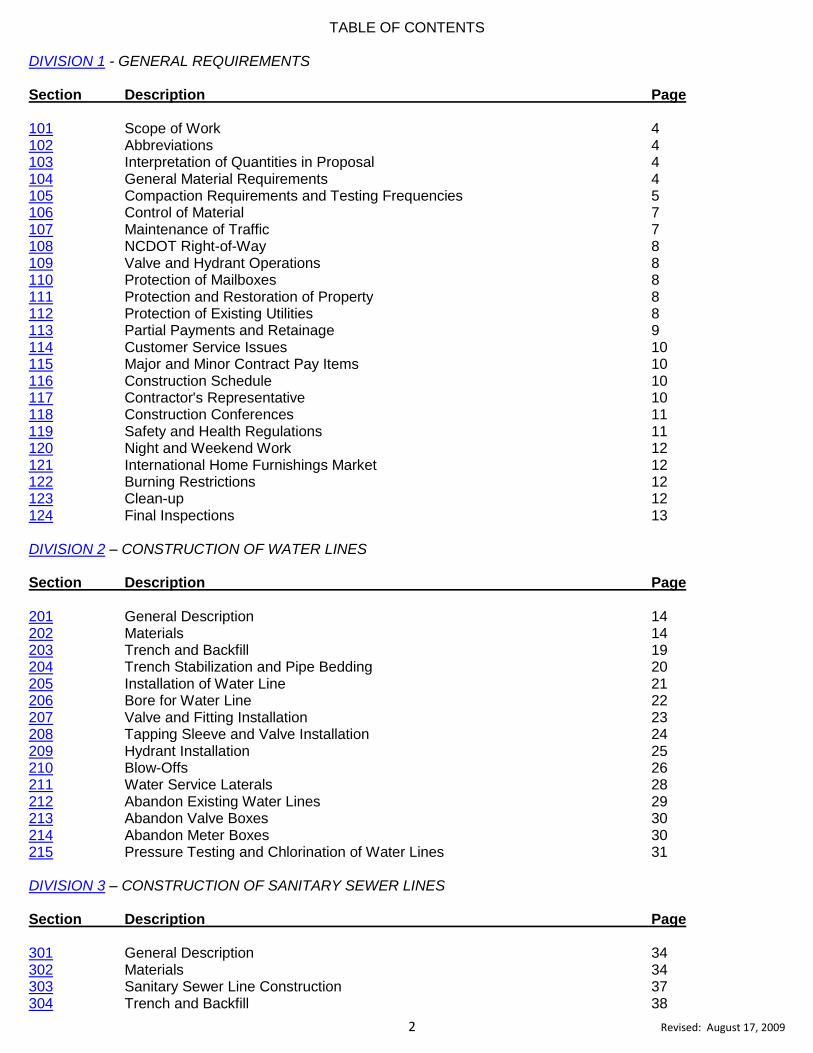
DIVISION 1 - GENERAL REQUIREMENTS Section Description Page 101 Scope of Work 4 102 Abbreviations 4 103 Interpretation of Quantities in Proposal 4 104 General Material Requirements 4 105 Compaction Requirements and Testing Frequencies 5 106 Control of Material 7 107 Maintenance of Traffic 7 108 NCDOT Right-of-Way 8 109 Valve and Hydrant Operations 8 110 Protection of Mailboxes 8 111 Protection and Restoration of Property 8 112 Protection of Existing Utilities 8 113 Partial Payments and Retainage 9 114 Customer Service Issues 10 115 Major and Minor Contract Pay Items 10 116 Construction Schedule 10 117 Contractor's Representative 10 118 Construction Conferences 11 119 Safety and Health Regulations 11 120 Night and Weekend Work 12 121 International Home Furnishings Market 12 122 Burning Restrictions 12 123 Clean-up 12 124 Final Inspections 13 DIVISION 2 – CONSTRUCTION OF WATER LINES Section Description Page 201 General Description 14 202 Materials 14 203 Trench and Backfill 19 204 Trench Stabilization and Pipe Bedding 20 205 Installation of Water Line 21 206 Bore for Water Line 22 207 Valve and Fitting Installation 23 208 Tapping Sleeve and Valve Installation 24 209 Hydrant Installation 25 210 Blow-Offs 26 211 Water Service Laterals 28 212 Abandon Existing Water Lines 29 213 Abandon Valve Boxes 30 214 Abandon Meter Boxes 30 215 Pressure Testing and Chlorination of Water Lines 31 DIVISION 3 – CONSTRUCTION OF SANITARY SEWER LINES
Section Description Page 301 General Description 34 302 Materials 34 303 Sanitary Sewer Line Construction 37 304 Trench and Backfill 38

3 Revised: August 17, 2009
305 Trench Stabilization and Pipe Bedding 40 306 Manhole Construction 41 307 Extension Inserts for Manhole Frames 43 308 Installation of Sewer Pipe into Existing Manholes 43 309 Coring Existing Precast Manholes 43 310 Build Invert in Existing Manhole 43 311 Convert Existing Manhole to Drop Manhole 44 312 Sewer Laterals & Appurtenances 44 313 Sanitary Sewer Service (New & Rehab) 45 314 Sewer Force Mains 46 315 Abandon Existing Sanitary Sewer Lines 47 316 Abandon Existing Sanitary Sewer Manholes 47 317 Pipe Plugs 48 318 Abandon Sewer Laterals 48 319 Visual Inspection and Testing of Sewer Lines 49 320 Vacuum Testing of Manholes 50 321 Video Inspection of Sewer Lines 50 322 Force Main Testing 50 DIVISION 4 - WORK COMMON TO WATER AND SEWER LINE CONSTRUCTION Section Description Page 401 General Description 52 402 Mobilization 52 403 Subsurface Exploration 52 404 Traffic Control 53 405 Construction Stakes, Lines, & Grade 53 406 Rock Excavation 56 407 Select Backfill Material 59 408 Pavement Repair 60 409 Remove and Replace Concrete Flatwork 61 410 Remove and Replace Concrete Curb and Gutter 61 411 Incidental ABC Stone Base 62 412 Concrete Encasement of Manhole and Valve Box Castings in Pavement 63 413 Concrete Thrust Blocking 63 414 Encasement Pipe By Boring and Jacking Method 63 415 Service Saddles 64 416 Clearing and Grubbing 65 417 Selective Tree Removal 66 418 Fence Reset 66 419 Remove and Reset Driveway Pipe 67
DIVISION 5 - EROSION AND SEDIMENTATION CONTROL Section Description Page 501 General Description 68 502 Ground Cover Timelines 68 503 Temporary Mulch 68 504 Permanent Seeding & Mulching 69 505 Payment for Erosion Control 70 Appendix A Fitting Weight Chart 74
DIVISION 6 – INDEX 77
4 Revised: August 17, 2009
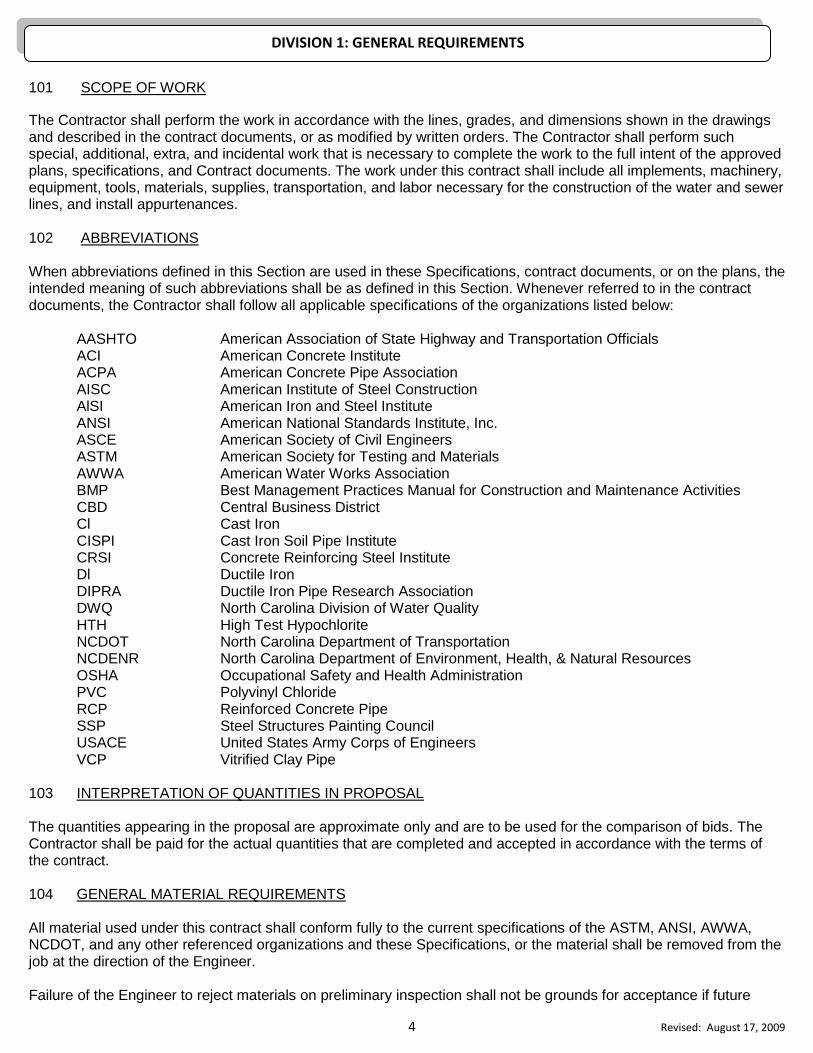
101 SCOPE OF WORK
The Contractor shall perform the work in accordance with the lines, grades, and dimensions shown in the drawings and described in the contract documents, or as modified by written orders. The Contractor shall perform such special, additional, extra, and incidental work that is necessary to complete the work to the full intent of the approved plans, specifications, and Contract documents. The work under this contract shall include all implements, machinery, equipment, tools, materials, supplies, transportation, and labor necessary for the construction of the water and sewer lines, and install appurtenances. 102 ABBREVIATIONS When abbreviations defined in this Section are used in these Specifications, contract documents, or on the plans, the intended meaning of such abbreviations shall be as defined in this Section. Whenever referred to in the contract documents, the Contractor shall follow all applicable specifications of the organizations listed below:
AASHTO American Association of State Highway and Transportation Officials ACI American Concrete Institute ACPA American Concrete Pipe Association AISC American Institute of Steel Construction AlSI American Iron and Steel Institute ANSI American National Standards Institute, Inc. ASCE American Society of Civil Engineers ASTM American Society for Testing and Materials AWWA American Water Works Association BMP Best Management Practices Manual for Construction and Maintenance Activities CBD Central Business District Cl Cast Iron CISPI Cast Iron Soil Pipe Institute CRSI Concrete Reinforcing Steel Institute Dl Ductile Iron DIPRA Ductile Iron Pipe Research Association DWQ North Carolina Division of Water Quality HTH High Test Hypochlorite NCDOT North Carolina Department of Transportation NCDENR North Carolina Department of Environment, Health, & Natural Resources OSHA Occupational Safety and Health Administration PVC Polyvinyl Chloride RCP Reinforced Concrete Pipe SSP Steel Structures Painting Council USACE United States Army Corps of Engineers VCP Vitrified Clay Pipe
103 INTERPRETATION OF QUANTITIES IN PROPOSAL The quantities appearing in the proposal are approximate only and are to be used for the comparison of bids. The Contractor shall be paid for the actual quantities that are completed and accepted in accordance with the terms of the contract. 104 GENERAL MATERIAL REQUIREMENTS All material used under this contract shall conform fully to the current specifications of the ASTM, ANSI, AWWA, NCDOT, and any other referenced organizations and these Specifications, or the material shall be removed from the job at the direction of the Engineer. Failure of the Engineer to reject materials on preliminary inspection shall not be grounds for acceptance if future
DIVISION 1: GENERAL REQUIREMENTS

5 Revised: August 17, 2009
defects are found. Where examples of approved items are listed by name, the cited examples are used only to denote the quality standard of product desired and they do not restrict bidders to a specific brand, make manufacturer or specific name. Any equivalent item proposed for use in lieu of a named item shall require submittal of a sample and cut-sheet to the City a minimum of 14 days prior to bid opening for evaluation. The City shall approve or disapprove of the equivalence of the item prior to bid opening. Any proposed equivalent item that has not been evaluated in accordance with the above procedure shall be declared non-equivalent for the purpose of the bid. Any item not declared equivalent by this procedure shall be refused acceptance upon delivery and shall be returned and replaced by an approved item at no additional cost to the City. 105 COMPACTION REQUIREMENTS AND TESTING FREQUENCIES:
All density tests shall be conducted at the direction of the Engineer by qualified technicians in accordance with this Section. The cost of such tests will be borne by the Owner with the provision that after two failing tests in the same location; the Contractor shall be required to submit satisfactory evidence that his compaction efforts meet the Specifications, and additional testing costs will be the Contractor’s responsibility. The Contractor shall be responsible for all settlement over trenches that may occur prior to the project acceptance and for a period of twelve months thereafter.
(1) Utility Trenches: Backfill for utility trenches shall be placed in 8-inch lifts or less of uncompacted soil and compacted with a mechanical tamp before placing additional layers. Backfill shall be compacted to 95% of the maximum dry density as determined by the AASHTO T99 Standard Proctor-NCDOT modified. When trenches are located within the roadway, the final 12” of shall be compacted to a density of 100% of the maximum dry density as determined by the AASHTO T99 Standard Proctor-NCDOT modified. Unless otherwise directed by the Engineer, all Cross country raw or transmission water lines or sanitary sewer outfalls shall be compacted to a density of 90% of the maximum dry density as determined by the AASHTO T99 Standard Proctor-NCDOT modified. The moisture content for the backfill used shall match the in-situ conditions unless otherwise directed by Engineer. Care shall be exercised in tamping directly above the pipe to prevent damage to the pipe. Trenches over 4 feet in depth shall meet safety requirements. Minimum testing requirements: No less than one field density test per 2 vertical feet in 300 linear feet, or shorter distances as directed by Engineer.
(2) Subgrade: Under Roadways and extending one foot beyond the proposed curb line, each 8” lift of subgrade shall be thoroughly compacted to a density of 95% of the maximum dry density as determined by the AASHTO T99 Standard Proctor-NCDOT modified for depths up to the final twelve (12) inches of subgrade. Compaction requirements shall be attained by the use of mechanical compaction methods. Soil moisture should be maintained to plus/minus 3% of optimum moisture content as determined by the Proctor or as directed by the Engineer. When using hand operated or walk-behind compaction equipment, the maximum loose lift size shall be 4”.
6 Revised: August 17, 2009
When using pull-behind or drive equipment, the maximum loose lift size shall be 8”. A density of 100% of the maximum dry density as determined by the AASHTO T99 Standard Proctor-NCDOT modified is required on the final twelve (12) inches. Each layer of backfill shall be placed loose and thoroughly compacted in place. Minimum testing requirements: No less than one field density test per 500 linear feet. (3) Embankment: Embankment shall be compacted to a density of 95% of the maximum dry density as determined by AASHTO T99 Standard Proctor-NCDOT modified. Minimum testing requirements: No less than one field density test per vertical foot in 300 linear feet.
(4) Slopes: The slopes shall be shaped to meet safety requirements based on the existing soil types. The finished slope shall not exceed a 2:1 for cut areas or 3:1 for fill areas; except as otherwise approved by the Engineer. Mowable slopes shall be compacted to a density equal to not less than 90% of the maximum dry density as determined by AASHTO T99 Standard Proctor-NCDOT modified, and shall be no steeper than 4:1 unless otherwise approved by Engineer. Contractor will be required to proof roll the right-of-way subgrade. (5) Aggregate Base Course Stone:
The maximum loose single layer of ABC is 8”. Depths greater than 8” should be compacted in two equal thickness layers. The ABC shall be compacted to a density equal to not less than 100% of the maximum dry density as determined by AASHTO T99 Standard Proctor-NCDOT modified. Minimum testing requirements: No less than one field density test per vertical foot in 500 linear feet. (6) Concrete Aprons, Curb and Gutters, Driveways, Sidewalks, Misc. Structures: The fill or embankment material (to at least 6 inches each side of the edge of the slab) shall be compacted to a density equal to not less than 95% of the AASHTO T99 Standard Proctor-NCDOT modified. Minimum testing requirements: Not less than one field density test per 500 linear feet of curb & gutter, and one field density test per 500 linear feet of sidewalk which will include areas for aprons, wheel chair ramps, and other structures. Air content should be 6.0% +/- 1.5% and is subject to testing. The maximum slump shall conform to Section
202-I of these Specifications.
Concrete temperature, air temperature shall be verified on 1st load and at least once every 50 yards thereafter. Cylinders: for each day’s pour, or a minimum of one test per 100 cubic yards or 500 linear feet.
The City will perform such destructive and non-destructive testing as it deems necessary; procedures will follow those of the American Society for Testing and Materials (ASTM), the American Association of State Highway and Transportation Officials (AASHTO), or other appropriate testing related organizations. The City reserves the right to modify testing procedures for backfill compaction to allow a deeper test to be made using the sand-cone method;
7 Revised: August 17, 2009
nuclear testing gauges may be employed for density measurements on stone or asphalt. Material specimens shall be subject to testing by an independent testing laboratory at the direction of the Engineer. All costs associated with the materials and testing will be borne by the City. The Engineer will order rejection of materials not meeting Specifications, and such materials shall be immediately removed from the job. The Contractor may employ an approved independent testing agency to check the results of tests conducted by the City. Should such tests prove that the City test results are incorrect and the employed agency test results are within the limits specified, the cost of the employed agency tests will be borne by the City; otherwise the Contractor will bear the cost. No direct payment will be made for the extra compactive effort as such work will be considered incidental to other work being paid for by the various items in the contract. 106 CONTROL OF MATERIAL All pipe and appurtenances that are to become a part of the City's water and sewer systems shall be stored and handled in such a manner to preserve their quality and fitness for the work, and prevent no storm water or any foreign material will contaminate the interior surfaces. All hydrants and valves shall be stored so that no damage from freezing will occur. Materials damaged during delivery or handling shall not be used without approval of the Engineer. Stored materials shall be located as to facilitate their inspection and are subject to inspection at any time, and shall meet the Specification requirements at the time they are put into use. Subject to the approval of the Engineer, material prepayment for stored materials will be paid at ninety (90) percent of the actual invoice cost. The Contractor may use the City’s right-of-way for storage purposes, and equipment. The Contractor shall restore the said right-of-way to its original condition at no expense to the City. The Contractor shall be held responsible for all material furnished by him, and shall replace material that is defective, damaged, or does not conform to the Specifications at no expense to the City. The Contractor shall furnish all materials necessary to complete the work, except any materials specified in the Special Provisions to be furnished by the City. Payment at the contract price for the item, which includes the use of City furnished material, will be full compensation for all cost of handling and placing such materials after they are delivered or made available to the Contractor. The Contractor will be held responsible for all material furnished to him, and deductions will be made from any money due him to make good any shortage and deficiencies from any cause whatsoever and for any damage which may occur after City furnished material has been made available. All materials that do not conform to the Specifications shall be considered as defective and such materials, whether in place or not, shall be rejected and are to be removed from the site of the work unless permitted otherwise by the Engineer. No rejected material, the defects of which may have been substantially corrected, may be used until the Engineer has given approval. 107 MAINTENANCE OF TRAFFIC The Contractor shall maintain the project in a safe and practical way to minimize unnecessarily delayed or inconvenienced motorist using the roadways due to the work being carried on by the Contractor. The Contractor shall bear all costs associated with maintaining public traffic and access to individual residences to the satisfaction of the Engineer. The Contractor shall indemnify and save harmless the City and all its officials, agents, employees, from all suits, actions, or claims of any character, name or descriptions brought forward due to any injuries or damages received or sustained in consequence of any neglect in maintaining traffic as specified.

8 Revised: August 17, 2009
108 NCDOT RIGHT-OF-WAY When construction is performed in the NCDOT right-of-way, the Contractor shall adhere to all NCDOT policies, procedures, and permits. The City will obtain encroachment permits for installations in the highway rights-of-way, and the Contractor shall have a copy of the encroachment permit on the job site. The Contractor shall notify the NCDOT prior to beginning work in the NCDOT right-of-way, and shall install and maintain applicable traffic control devices during the life of the project. 109 VALVE AND HYDRANT OPERATIONS The Contractor shall not operate any valve or hydrant within the City water system that has system pressure against it, without permission. Prior to operating any water valve(s) or fire hydrants on/near a project, the Contractor shall coordinate with the City’s project inspector to obtain permission and the necessary procedures that must be followed. The project inspector will contact the City’s Water Sewer Mains Division at 336-883-3466 or 336-883-3038. A map illustrating the water valves located within the project limits may be picked up at the Water Sewer Mains Division office located at the City of High Point MOC at 816 East Green Drive. The Contractor shall promptly report all unaccounted for water loss associated with new construction to the project inspector. The project inspector shall document the unaccounted for water loss on authorized forms and submit to the Ward Filtration Water Plant Superintendent. The Contractor is hereby made aware that any violation of the above requirements is punishable as outlined in Section 8-2-30 of the City of High Point Code of Ordinances. 110 PROTECTION OF MAILBOXES The Contractor shall be responsible for the removal, preservation, maintaining the mailboxes in such a condition that the Postal Service can deliver mail to the boxes, and resetting mailboxes disturbed by construction operations. When mailboxes and their supports are reset, they shall be in a condition equal to or better than the original condition. No direct payment will be made for removing, preserving, resetting, or maintaining mailboxes in Postal delivery condition. This work will be considered incidental to other work being paid for under the various items in the contract. Extra compensation will be made when, in the opinion of the Engineer, repair or replacement is required to properly reset a mailbox. This extra compensation will not be made for damages to mailboxes or their supports that is caused by negligence of the Contractor. 111 PROTECTION AND RESTORATION OF PROPERTY The Contractor shall be responsible for the protection from his activities of all public and private property on and adjacent to the work and shall use every reasonable precaution necessary to prevent damage to pipes, conduits, and other underground structures, trees, poles, wires, cables, and other overhead structures. The Contractor shall not remove land monuments or property markers until directed by Engineer. The Contractor shall protect all land monuments and property markers from disturbance or damage until the Engineer has referenced their location. The Contractor will be held responsible for all damage or injury resulting from any act, omission, negligence, or misconduct in the prosecution of the work. The Contractor shall either restore at his own expense such property to a condition similar or equal to that existing before such damage or injury was done, or shall make good such damage or injury in a manner acceptable to the owner of the damaged property and to the City. In case of failure on the part of the Contractor to restore such property or make good such damage or injury the City may repair, rebuild, or otherwise restore such property in such manner as the Engineer considers necessary at the Contractor's expense. 112 PROTECTION OF EXISTING UTILITIES The Contractor shall explore the area ahead of ditching operation by observation, electronic devices, personal contacts with the utility companies, and locating utilities in advance of the trenching operations. The Contractor shall

9 Revised: August 17, 2009
conduct his work in a manner that minimizes damage to existing structures or utilities, and shall be held responsible for any damages resulting from not exploring the area ahead, negligence, careless operations, or damages to existing pipe, wire, structures, etc. All construction must conform to the underground utility protection act of North Carolina. CONTACT THE ONE-CALL CENTER @ 1-800-632-4949 or 811 a minimum of 48 hours prior to digging. 113 PARTIAL PAYMENTS AND RETAINAGE
The Contractor’s attention is directed to the fact that periodic payments and retainage shall conform to G.S 143-134.1 and the following: A. Contracts Costs less than $100,000.00: No retainage on periodic or final payments will be retained by the City on construction contracts in which the total contract costs are less than one hundred thousand ($100,000.00) dollars. B. Contracts Costs greater than or equal to $100,000.00: Retainage on periodic or final payments on construction contracts in which the total contract costs are equal to or greater that one hundred thousand ($100,000.00) dollars will be as follows: The City shall withhold an amount equal to five (5) percent of the billed partial payments will be deducted and retained by the City until fifty (50) percent of the total work has been completed. When the Contract payments total fifty (50) percent of the contract bid amount, the City with written consent of the Surety, shall not retain any further retainage from periodic payments due to the Contractor as long as the Contractor continues to perform satisfactory work, and nonconforming work identified in writing prior to that time by the City has been corrected by the Contractor. (1) If the City deems the Contractor’s performance is unsatisfactory, the City may reinstate retainage for each subsequent periodic payment application as authorized in G.S. 143-134.1 up to a maximum amount of five percent (5%). (2) The Contractor shall be deemed fifty percent (50%) complete when the Contractor’s gross contract invoices, excluding the value of materials stored off-site, equal or exceed fifty percent (50%) of the value of the Contract. The total value of stored on-site material shall not exceed twenty percent (20%) of the Contract’s gross contract invoices. (3) Upon substantial completion and with written consent of the Surety, the City shall pay an amount equal to one hundred percent (100%) of the work completed less two and one half (2.5) times the value of the remaining work to be corrected in order to secure completion or correction of work. (4) Written consent of Surety to reduce retainage and make final payment shall be mailed directly to the City of High Point’s Engineering Services Department. C. Subcontractor Payment: The subcontractor shall be paid according to G.S.143-134.1 and the following:
(1) The Prime Contractor shall not excess the percentage of retainage being held on the subcontractor on payments made by the City to the Prime Contractor. (2) Within seven (7) days of receipt of payment of partial or final payments, the Prime Contractor shall pay each subcontractor based on the work completed or service provided under the subcontract. (3) If any periodic or final payment to the subcontractor is delayed more than seven (7) days after receipt of periodic or final payment by the Prime Contractor, the Prime Contractor shall pay the subcontractor interest beginning on the eight day at a rate of one percent (1%) per month or fraction

10 Revised: August 17, 2009
thereof on the unpaid due balance. The Contractor shall supply the original delivery tickets and NPDES documentation with all periodic and final payment requests. No photocopies of delivery tickets will be accepted for payment without the Engineer’s permission. The City will make payment to the Contractor for all completed and accepted work within 30 days of receipt of an approved estimate from the Contractor. Payment of any monies to the Contractor is contingent upon the submittal by the Contractor of an estimated contract monthly cash flow schedule for the total contract period 30 days prior to the initial request for payment.
114 CUSTOMER SERVICE ISSUES The Contractor shall respond to all construction related concerns or complaints within 24 hours of receipt and resolve the concern within a reasonable timeframe. The Contractor shall be responsible for tracking all customer service issues including but not limited to: property damage claims, drainage issues, backfill materials, clean-up operations, driveway and access issues, flooding, erosion control, mailbox reset, meter and clean-out locations, and landscaping issues. The Contractor shall provide a minimum of 24 hours advance notice to an affected property owner/occupant for any service reductions including but not limited to: driveways, parking, street or lane closures, and disruption of any type of communications cable, gas, water, and sewer services. There is no direct payment for “Customer Service Issues” as such work is considered to be incidental to the contract. The monthly contract payment will not be released until all customer service issues have been resolved and a Complaint Log and Tracking Sheet has been submitted and approved with the monthly estimate. When the contract expenditures reached 50%, the Contractor’s efforts and abilities to respond to and resolve customer service issues will be reviewed prior to any reduction of retainage. 115 MAJOR AND MINOR CONTRACT PAY ITEMS Major contract pay items will be listed in the contract special provisions. All other original contract pay items and pay items associated with extra work shall be considered “Minor” pay items. The Engineer reserves the right to make changes in quantities in order to complete the project as described in Section 104-5 of the NCDOT’s Standard Specifications for Roads and Structures, Latest Edition. 116 CONSTRUCTION SCHEDULE Within 30 days following the contract award, the Contractor shall prepare and submit to the Engineer two (2) copies of the proposed construction schedule for the duration of the contract. 117 CONTRACTOR'S REPRESENTATIVE
A. On Site Personnel: When work is being performed under this contract, the Contractor shall have present one competent individual who’s authorized to act in a supervisory capacity over all work on the project(s) including sub-contractor work. This individual shall be experienced in the type of work being performed, capable of managing, directing, coordinating the work, reading and thoroughly understanding the contract documentation and plans, and receiving and carrying out directions from the Engineer or his authorized representative. Unless otherwise approved by the Engineer, this individual shall be an employee of the Contractor. The Contractor shall have present on each project at least one permanent employee that can read, understand, and speak fluent English.

11 Revised: August 17, 2009
B. On Call Personnel: During the life of this contract, the Contractor shall provide one permanent employee that shall be available at the work site within three (3) hours, and shall have the authority and capability for project responsibility.
118 CONSTRUCTION CONFERENCES
A. Preconstruction Conference: Prior to commencing work and after award of the project, a preconstruction conference will be scheduled at a mutually agreeable time for the Contractor and the Engineer. B. Construction Conferences: The construction conferences are to be scheduled at times that are mutually agreeable to the Contractor and the Engineer and shall be periodically once the work begins. It shall be the responsibility of the Contractor or his Representative to attend the conferences.
119 SAFETY AND HEALTH REGULATIONS The Contractor shall comply with all applicable safety and health regulations, standards, and codes including but not limited to: OSHA requirements in the General Industry (1910) and Construction (1926) Standards, NC OSHA Guidelines and Regulations, (MUTCD, NFPS’S Life Safety Code 101, and North Carolina Building Code and other state and local regulations as they apply.) The City of High Point, its officers, and employees do not propose to administer, implement, or be responsible for the Contractor’s safety and health program. The City will not provide any legal, insurance, safety advice, and/or counsel to the Contractor, subcontractor or their employees, unless agreed upon in a written contract. The City shall have access to any worksite, permits or safety related documentation upon request. All fatal or serious incidents resulting in the hospitalization of any persons much be reported to the City immediately and in writing within eight hours. Other occurrences with serious accident potential, such as equipment failures, slides, and cave-ins must be reported to the City immediately. Investigations, inspections, citations, or work stoppage must be reported immediately. The City reserves the right to suspend work and/or terminate the contract if safety procedures are not followed, or if there is a refusal to comply. A Contractor selected by the City will complete the unfinished work, and the cost of completion of work and any claims arising from the completed work will be the responsibility of the initial Contractor. Contractors will be responsible for:
a. Erecting and maintaining all necessary safeguards to protect persons and property, including but not limited to properly securing materials and providing traffic control. If work is to impede traffic, the Contractor will comply with work zone traffic safety guidelines as noted in the MUTCD and supplements.
b. Notifying the owners of adjacent property and underground facilities and utility owners when
construction may affect them and cooperate in the protection, removal and replacement of their property.
c. Obtaining all necessary permits prior to construction, including a permit to close a public street when
the flow of traffic on the public street may be impeded. d. Training of employees and subcontractor’s employees as required by the OSHA standards and
providing the personal protective equipment needed to perform their tasks safely.

12 Revised: August 17, 2009
e. Writing a safety program covering the work performed and providing a copy of the program to employees.
f. Providing the name and phone numbers of an on-site Contractor employee who is responsible for safety.
g. Exceeding the minimum safety regulations to protect citizens, City employees, Contractor and
subcontractor employees, and/or property from harm related to the construction process as necessary or required by the City.
h. Warning those who may be injured by the Contractor or the subcontractors’ actions and taking
necessary precautions to protect those individuals from injury. i. Providing a “competent person” on the job at all times when work is being performed. j. Disposing of all waste generated by the Contractor including but not limited to paints, coolants, oils,
and construction debris shall be in accordance with Local, State, and federal regulations at the Contractors’ expense.
120 NIGHT AND WEEKEND WORK No night or weekend work requiring presence of the Engineer or the Inspector will be permitted except in case of emergency or the contract is deemed a “Special Project”. Operation of mechanical equipment or other work of noisy nature will not be permitted between the hours of 9:00 p.m. and 7:00 a.m. except in the case of an emergency or the contract is deemed a “Special Project.” The Contractor must obtain written consent from the Engineer prior to operating mechanical equipment between the hours specified above, or performing work at night or on a weekend that requires the presence of the Engineer or Inspector. 121 INTERNATIONAL HOME FURNISHING MARKET The Contractor should be aware that the International Home Furnishing Markets are held in High Point semiannually in April and October. During the market, the following restrictions shall apply:
All work within the Central Business District shall be completed thirty (30) days before beginning the spring and fall Markets. The spring and fall market dates are listed on the High Point Market website: http://www.highpointmarket.org No interruption of water service will be allowed without prior authorization from the Director of Public Services. The Contractor shall not work on any street(s) located within the CBD between the hours of 6:00 am to 9:00 am and 4:00 pm to 6:00 pm unless otherwise approved by the Engineer.
122 BURNING RESTRICTIONS Open burning will not be permitted on any portion of the construction limits established under this contract. All construction debris shall be properly disposed in accordance with applicable state or local rules and regulations. 123 CLEAN-UP During construction of the project, the Contractor shall maintain the work area, including portable restroom facilities, and adjacent streets in as neat a manner as can be reasonably expected. In the event that adjacent streets need to be cleaned or flushed due to negligence by the Contractor, the Contractor will be responsible for seeing that this work is done.

13 Revised: August 17, 2009
Upon completion of the entire project or any portion thereof, the Contractor shall perform all clean-up operations necessary to place the project in first class condition. This shall include, but not be limited to: cleaning all areas disturbed, shoulders, streets, utility structures, removing and disposing of all excess materials, trash, debris, etc. Disturbed areas, between the curb line and limits of grading, shall be hand raked and all brick, mortar, rock, clods, and other debris shall be removed and disposed of. It shall further be the Contractor's responsibility to maintain all areas disturbed until final acceptance of the project. 124 FINAL INSPECTIONS Prior to final inspection, the Contractor will insure that all structures are clear and free of debris, and all valve boxes shall be clean, such that valve wrench can make solid contact with the operating nut prior to final inspection. All miscellaneous brick, mortar, stone, asphalt, concrete or other debris shall be removed from the project and properly disposed. Hand raking of yards will have taken place and all seeding, mulching and erosion control completed. All meter boxes, cleanouts or other structures on the shoulder shall be uncovered and in plain view for the final inspection and shall match the surrounding ground elevation. The Contractor is instructed to request a final inspection only after the work has been checked by the Contractor or his appointed agent. When the Contractor has a project ready for final inspection, he shall inform the Engineer in writing and a date will be scheduled for the final inspection. The Engineer or his representative will meet with the Contractor's representative, and they shall make a thorough inspection of the job. The Contractor shall furnish all labor necessary to open and inspect all manholes, catch basins, and valve boxes. A list of all deficiencies shall be made by the City within one week of final inspection. The Contractor must correct the deficiencies prior to the acceptance of the project by the City. The Contractor shall complete the punch list within 30 days of receipt unless otherwise approved by the Owner. All defects observed by the Engineer during the final inspection shall be repaired by the Contractor at his expense.

14 Revised: August 17, 2009
201 GENERAL DESCRIPTION
This Section consists of those work common to water line construction. Construction operations that are unique to a particular water line will be covered in the contract "Special Provisions.” Operations that are common in the construction of both water and sanitary sewer lines are located in Division 4 of these Specifications. All work described herein is to be performed in accordance with the requirements in the drawings, Specifications, and the Contract documentation. 202 MATERIALS
A. Ductile Iron Pipe:
The interior of the pipe shall be cement lined and seal in accordance with ANSI A21.4/AWWA C104, and the exterior shall be coated with a bituminous coating in accordance with ANSI A21.53/AWWA C153. Ductile iron pipe shall be manufactured in accordance with ANSI A21.51 in 18-foot or 20-foot lengths. Pipe joints shall be push-on-type as per ANSI A21.51, Section 51-2-6.
(1) 3-Inch thru 12-Inch:
Water pipe nominal diameters between three inches and twelve inches shall be Pressure Class 350 pipe designed in accordance with ANSI A21.50 for a working pressure of 350 psi. (2) 16-Inch and Larger:
Water pipe nominal diameters sixteen inches and larger shall be Pressure Class 250 designed in accordance with ANSI A21.50 for a working pressure of 250 psi. B. Copper Pipe: Two-Inch and smaller water pipe for water service laterals shall be Type K soft copper conforming to ASTM B-88. C. Pipe Fittings:
Standard Ductile iron fittings shall be mechanical joint fittings that meet the requirements of ANSI A21.10/AWWA C110. All glands shall be ductile iron, not gray iron. The interior of all fittings will be cement lined in accordance with ANSI A21.4/AWWA C104 and the exterior of all fittings shall be coated with a bituminous coating in accordance with ANSI A21.53/AWWA C153. Fittings shall have a minimum pressure rating of 250 psi and are subject to approval by the Engineer. Rubber gasket joints shall conform to ANSI A21.11/AWWA C111. Ductile iron compact fittings (three (3”) to twenty-four (24”) inches) shall conform to ANSI A21.53/AWWA C153 with a minimum pressure rating of 350 psi. All fittings shall be stamped with the letters “DI” or word “DUCTILE” on each fitting.
D. Retainer Glands:
Retainer glands for connection to existing water lines shall be Meg-A-Lug type as manufactured by EBAA Iron, series 1100; or approved equal. Retainer glands shall be rated at a working pressure of 250 psi with a minimum safety factor of 2:1. Factory restrained joint pipe shall be used for construction of new water lines.
DIVISION 2: CONSTRUCTION OF WATER LINES
15 Revised: August 17, 2009
E. Valves: (1) Valves 12-Inches and Smaller: Valves 12-Inches and smaller shall be resilient wedge gate valves conforming to AWWA C509 with a working pressure of 250 psi, O-ring sealing, 2" square operating nut, open left and mechanical joint ends. Valves manufactured of ductile iron shall meet all applicable requirements of AWWA C515 with a working pressure of 250 psi. All interior and exterior ferrous metal surfaces shall be coated with a minimum of 8 mils of fusion-bonded coating meeting the requirements of AWWA C550. Valves may be used in sizes 4" thru 12" (Mueller, American Flow Control, M&H, Clow, Kennedy, U.S. Pipe, equivalent).
(2) Valves 16-Inch and larger:
Valves 16 inches and larger shall be vertical resilient wedge gate or butterfly valves as specified on the construction plans.
a. Vertical Resilient Wedge Gate Valves: Shall conform to the applicable requirements of AWWA C509 with a working pressure of 250 psi, and manufactured of ductile iron. Valves shall have O-ring sealing, 2" square operating nut, open left, and mechanical joint ends (American Flow Control, Clow, U.S. Pipe, equivalent). All interior and exterior ferrous metal surfaces shall be coated with a minimum of 8 mils of fusion-bonded epoxy paint meeting the requirements of AWWA C550.
b Butterfly Valves: Shall conform to the applicable requirements of AWWA C-504 with a working pressure of 150 psi. The valves shall have a 2” square operating nut that opens left, horizontal shafts manufactured of stainless steel and the body manufactured of cast iron with mechanical joint ends (Mueller, Pratt, M&H, equivalent).
Valve operator/actuator shall be for buried service and of the traveling nut or link and lever design with AWWA stops capable of absorbing 450 foot-pounds of input torque. Valves shall have resilient seating and the seat ring shall be manufactured of stainless steel. All internal parts shall be factory coated with a minimum of 8 mils of liquid or fusion bonded epoxy, AWWA approved for potable water. External iron surfaces shall be coated with a minimum of two coats of black asphaltic paint. (3) Surge Relief, Pressure Reducing and Altitude Valves:
Surge relief, pressure reducing and altitude valves shall be flanged iron globe body; fully bronze mounted; external pilot operated with free floating piston operated without springs, diaphragm, or levers; single seat with seat bore equal to size of valve. Valves shall be manufactured in accordance with AWWA C506 (Ross, equivalent). All surfaces of iron castings shall be coated with a minimum of two coats of a serviceable grade of asphaltic base metal paint. The valve design shall be such that repairs and internal dismantling of the main valve may be done without removing the valve from the water main. Valve working and surge pressures will be shown on the drawings or designated in the Contract "Special Provisions."
(4) Check Valves:
Check valves shall be swing type with iron body and flanged ends, meeting all requirements of AWWA C508. Valves to have an iron disc with bronze disc ring and seat ring and lever and weight
16 Revised: August 17, 2009
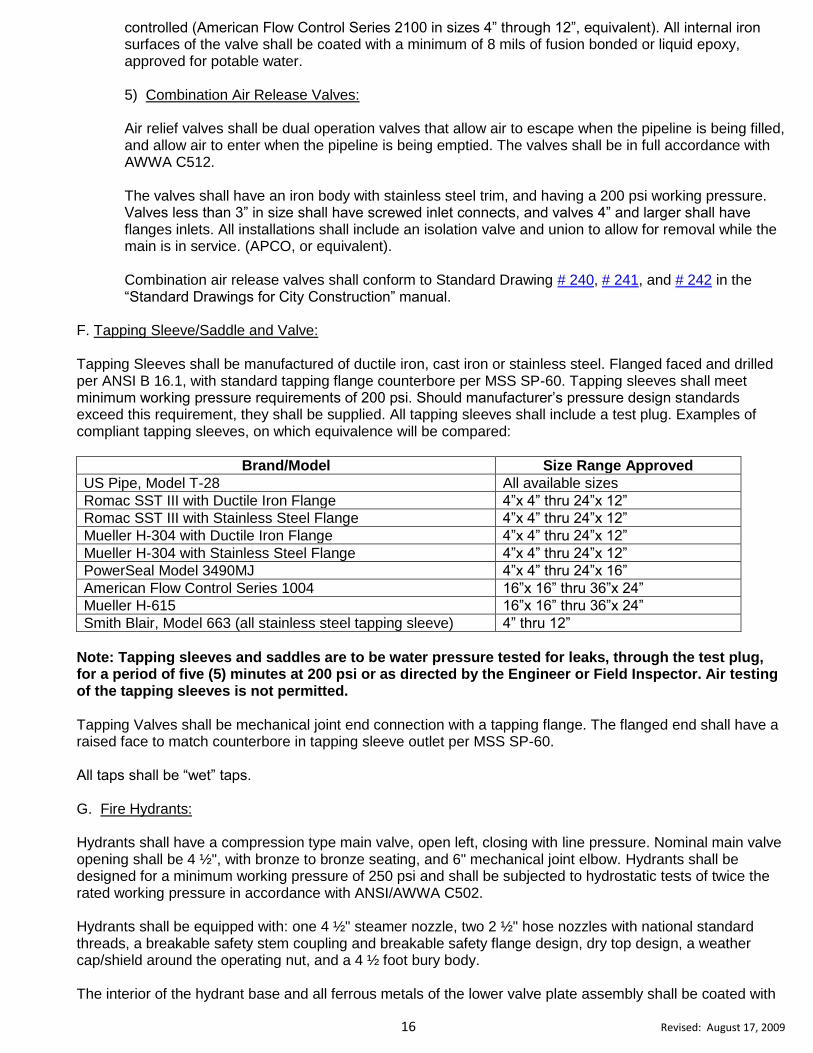
controlled (American Flow Control Series 2100 in sizes 4” through 12”, equivalent). All internal iron surfaces of the valve shall be coated with a minimum of 8 mils of fusion bonded or liquid epoxy, approved for potable water. 5) Combination Air Release Valves: Air relief valves shall be dual operation valves that allow air to escape when the pipeline is being filled, and allow air to enter when the pipeline is being emptied. The valves shall be in full accordance with AWWA C512. The valves shall have an iron body with stainless steel trim, and having a 200 psi working pressure. Valves less than 3” in size shall have screwed inlet connects, and valves 4” and larger shall have flanges inlets. All installations shall include an isolation valve and union to allow for removal while the main is in service. (APCO, or equivalent). Combination air release valves shall conform to Standard Drawing # 240, # 241, and # 242 in the “Standard Drawings for City Construction” manual.
F. Tapping Sleeve/Saddle and Valve:
Tapping Sleeves shall be manufactured of ductile iron, cast iron or stainless steel. Flanged faced and drilled per ANSI B 16.1, with standard tapping flange counterbore per MSS SP-60. Tapping sleeves shall meet minimum working pressure requirements of 200 psi. Should manufacturer’s pressure design standards exceed this requirement, they shall be supplied. All tapping sleeves shall include a test plug. Examples of compliant tapping sleeves, on which equivalence will be compared:
Brand/Model Size Range Approved
US Pipe, Model T-28 All available sizes
Romac SST III with Ductile Iron Flange 4”x 4” thru 24”x 12”
Romac SST III with Stainless Steel Flange 4”x 4” thru 24”x 12”
Mueller H-304 with Ductile Iron Flange 4”x 4” thru 24”x 12”
Mueller H-304 with Stainless Steel Flange 4”x 4” thru 24”x 12”
PowerSeal Model 3490MJ 4”x 4” thru 24”x 16”
American Flow Control Series 1004 16”x 16” thru 36”x 24”
Mueller H-615 16”x 16” thru 36”x 24”
Smith Blair, Model 663 (all stainless steel tapping sleeve) 4” thru 12”
Note: Tapping sleeves and saddles are to be water pressure tested for leaks, through the test plug, for a period of five (5) minutes at 200 psi or as directed by the Engineer or Field Inspector. Air testing of the tapping sleeves is not permitted. Tapping Valves shall be mechanical joint end connection with a tapping flange. The flanged end shall have a raised face to match counterbore in tapping sleeve outlet per MSS SP-60. All taps shall be “wet” taps. G. Fire Hydrants: Hydrants shall have a compression type main valve, open left, closing with line pressure. Nominal main valve opening shall be 4 ½", with bronze to bronze seating, and 6" mechanical joint elbow. Hydrants shall be designed for a minimum working pressure of 250 psi and shall be subjected to hydrostatic tests of twice the rated working pressure in accordance with ANSI/AWWA C502. Hydrants shall be equipped with: one 4 ½" steamer nozzle, two 2 ½" hose nozzles with national standard threads, a breakable safety stem coupling and breakable safety flange design, dry top design, a weather cap/shield around the operating nut, and a 4 ½ foot bury body. The interior of the hydrant base and all ferrous metals of the lower valve plate assembly shall be coated with
17 Revised: August 17, 2009
a minimum of 8 mils of fusion bonded or brush applied liquid epoxy. The liquid epoxy shall be AWWA approved for potable water. The Contractor shall paint the fire hydrants in accordance with AWWA standards and Standard Drawing #235 in the “Standard Drawings for City Construction” manual. The final coat of paint shall be applied after the fire hydrants have been installed. Hydrants shall comply with AWWA Standard C-502, including compliance to the maximum permissible loss of head for hydrants (Mueller Centurion, Kennedy K-81A, K-73, AVK, equivalent). The Contractor shall furnish different bury hydrants or provide suitable extensions at locations shown on the plans or designated by the Engineer. The Contractor may use hydrant/swivel tee. Payments for the different bury or extension will be made as outlined in Section 207 of these Specifications. H. METER BOXES:
(1) ¾” Water Meter Box for use with ¾” Water Service: Meter box body and lid shall be non traffic load rated, made of cast iron, and shall be rated in accordance with ASTM A-48, Class 30 B. (Sigma Corp. MB-388T, or approved equivalent). (2) 1” Water Meter Box for use with 1” Water Service:
Meter box body and lid shall be non traffic load rated, made of cast iron, and shall be rated in accordance with ASTM A-48, Class 30 B. (Sigma Corp. MB-381T, or approved equivalent). (3) 1 ½” And 2” Meter Box for use with 1 ½ and 2” Water Service: Meter box body and lid shall be non traffic load rated, made of cast iron, and shall be rated in accordance with ASTM A-48, Class 30 B. (Sigma Corp. MB-2202T, or approved equivalent). Meter boxes located in traffic bearing areas shall be traffic bearing rated for a static design load of 15,000 pounds over a 10” X 10” area, and must pass a minimum static test load of 22,500 pounds. All traffic bearing meter boxes shall have concrete collars.
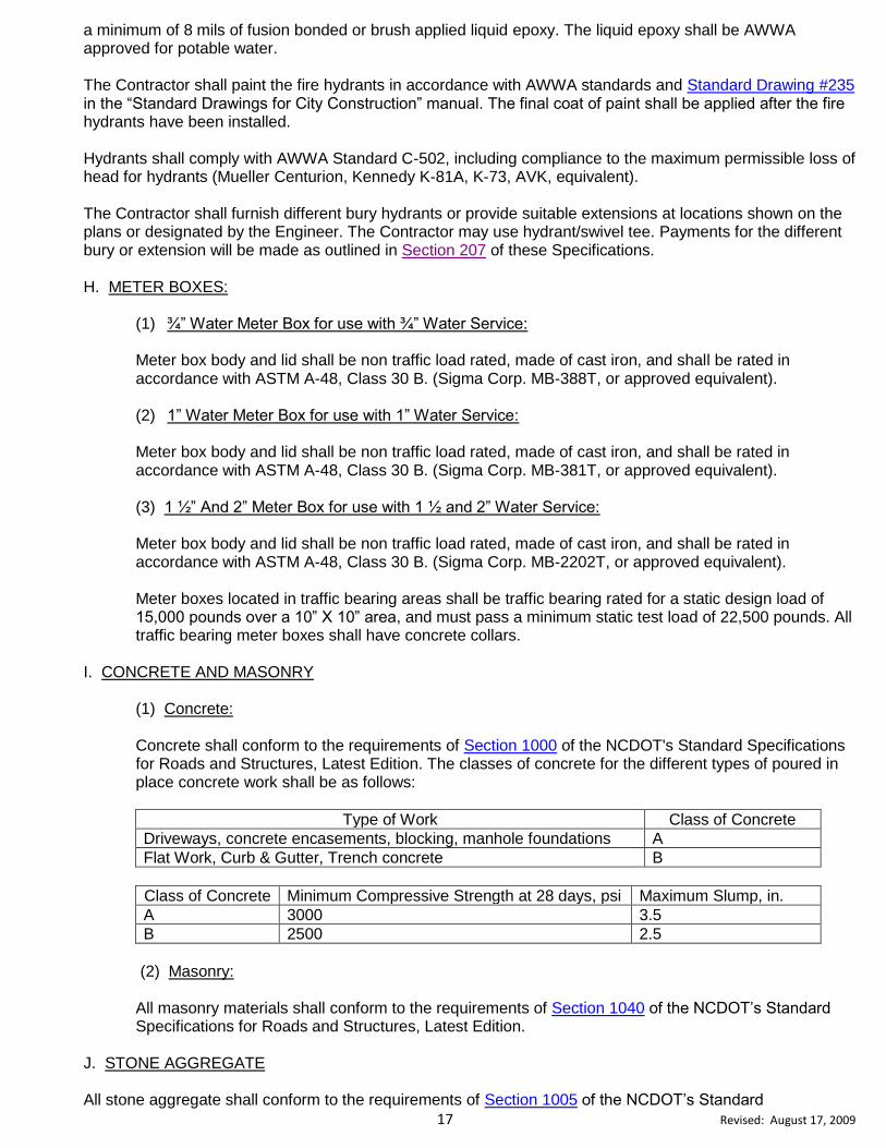
I. CONCRETE AND MASONRY
(1) Concrete:
Concrete shall conform to the requirements of Section 1000 of the NCDOT's Standard Specifications for Roads and Structures, Latest Edition. The classes of concrete for the different types of poured in place concrete work shall be as follows:
Type of Work Class of Concrete
Driveways, concrete encasements, blocking, manhole foundations A
Flat Work, Curb & Gutter, Trench concrete B
Class of Concrete Minimum Compressive Strength at 28 days, psi Maximum Slump, in.
A 3000 3.5
B 2500 2.5
(2) Masonry:
All masonry materials shall conform to the requirements of Section 1040 of the NCDOT’s Standard Specifications for Roads and Structures, Latest Edition.
J. STONE AGGREGATE All stone aggregate shall conform to the requirements of Section 1005 of the NCDOT’s Standard

18 Revised: August 17, 2009
Specifications for Roads and Structures, Latest Edition. Aggregate gradation shall conform to Table 1005-1 of the Standard Specifications. K. BITUMINOUS CONCRETE PLANT MIXES All bituminous concrete plant mixes shall conform to the requirements of the applicable Sections of Division 6 of the NCDOT’s Standard Specifications for Roads and Structures, Latest Edition. L. IRON CASTINGS
Manhole rings and covers, valve boxes, grates, and other miscellaneous castings shall conform to the applicable details and dimensions shown in the “Standard Drawings for City Construction” manual. M. TRANSITION COUPLINGS All transition couplings are to be Mueller, Maxi Fit, Fernco-Strong Back, Mission, Romac, Gladding-McBean Repair Couplings, or pre-approved equal.
N. SERVICE LINE INSTALLATION (NEW):
Water Laterals shall be Type K soft copper tubing, conforming to ASTM B-88-62. Couplings for tubing shall have compression connections. Examples of compliant compression corporation stops and meter setters:
(1) COMPRESSION CORPORATION STOPS (Ball Type)
Size Mueller Ford A.Y. McDonald
¾” 300 Ball Corp. valve B-25008 series FB1000-3-Q Brass 4701BT-3/4”
1” 300 Ball Corp. valve B-25008 series FB1000-4-Q Brass 4701BT-1”
1-1/2” 300 Ball Corp. valve B-25008 series FB1000-6-Q Brass 4701BT-1 ½”
2” 300 Ball Corp. valve B-25008 series FB1000-7-Q Brass 4701BT-2”
(2) CURB STOPS (Ball Type-Blow Off)
Size Mueller Ford A.Y. McDonald
¾” B25172 B41-333 6102W 22 or WT
1” B B25172 B41-444 6102W 22 or WT
1 B25172 B41-666 6102W 22 or WT
2” B B25172 B41-777 6102W 22 or WT
O. SERVICE LINE INSTALLATION (REHAB):
Water Laterals shall be Type K soft copper tubing, conforming to ASTM B-88-62. Couplings for tubing shall have compression connections. Examples of compliant compression corporation stops and meter setters: (1) COMPRESSION STOPS (Ball Type)
Size Mueller Ford A.Y. McDonald
¾” 300 Ball Corp. valve B-25008 series FB1000-3-Q Brass 4701BT-3/4”
1” 300 Ball Corp. valve B-25008 series FB1000-4-Q Brass 4701BT-1”
1-1/2” 300 Ball Corp. valve B-25008 series FB1000-6-Q Brass 4701BT-1 ½”
2” 300 Ball Corp. valve B-25008 series FB1000-7-Q Brass 4701BT-2”
19 Revised: August 17, 2009
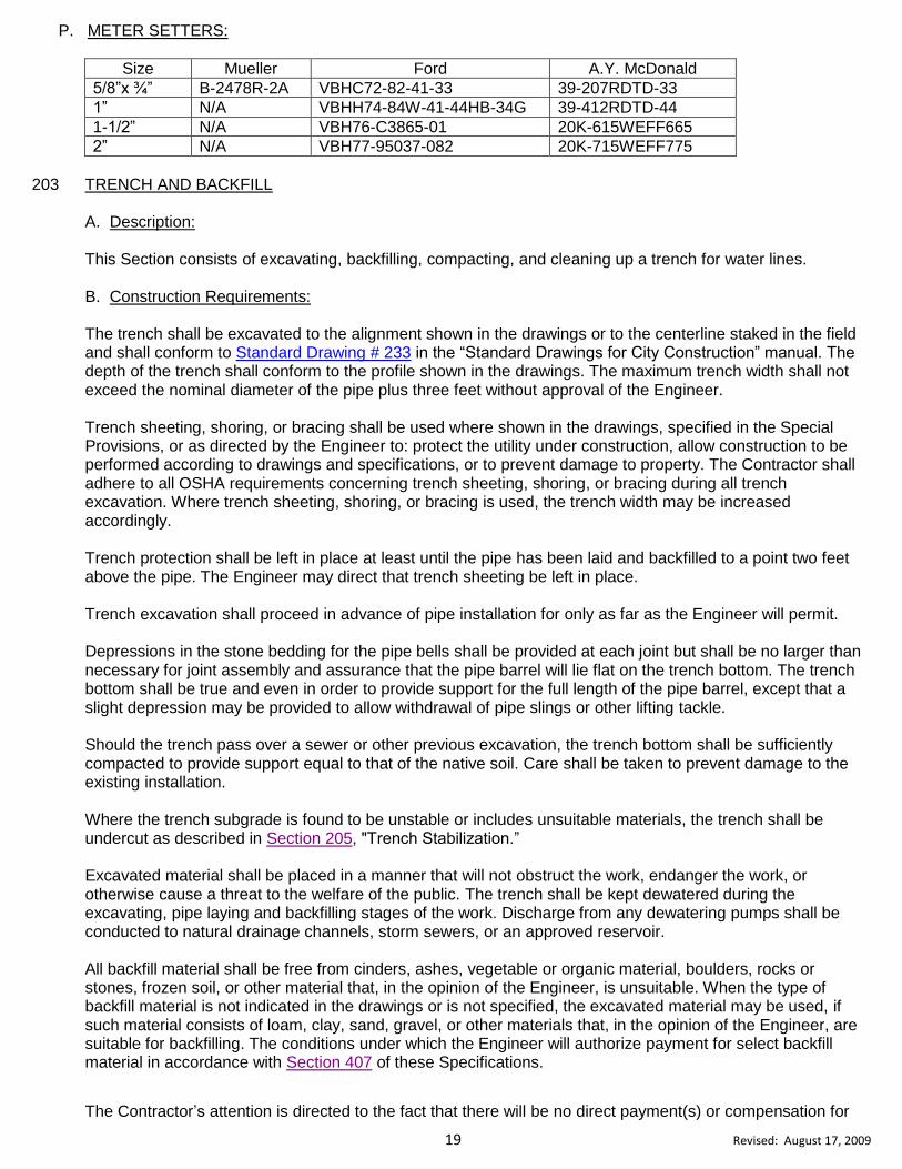
P. METER SETTERS:
Size Mueller Ford A.Y. McDonald
5/8”x ¾” B-2478R-2A VBHC72-82-41-33 39-207RDTD-33
1” N/A VBHH74-84W-41-44HB-34G 39-412RDTD-44
1-1/2” N/A VBH76-C3865-01 20K-615WEFF665
2” N/A VBH77-95037-082 20K-715WEFF775
203 TRENCH AND BACKFILL A. Description:
This Section consists of excavating, backfilling, compacting, and cleaning up a trench for water lines. B. Construction Requirements:
The trench shall be excavated to the alignment shown in the drawings or to the centerline staked in the field and shall conform to Standard Drawing # 233 in the “Standard Drawings for City Construction” manual. The depth of the trench shall conform to the profile shown in the drawings. The maximum trench width shall not exceed the nominal diameter of the pipe plus three feet without approval of the Engineer. Trench sheeting, shoring, or bracing shall be used where shown in the drawings, specified in the Special Provisions, or as directed by the Engineer to: protect the utility under construction, allow construction to be performed according to drawings and specifications, or to prevent damage to property. The Contractor shall adhere to all OSHA requirements concerning trench sheeting, shoring, or bracing during all trench excavation. Where trench sheeting, shoring, or bracing is used, the trench width may be increased accordingly. Trench protection shall be left in place at least until the pipe has been laid and backfilled to a point two feet above the pipe. The Engineer may direct that trench sheeting be left in place. Trench excavation shall proceed in advance of pipe installation for only as far as the Engineer will permit. Depressions in the stone bedding for the pipe bells shall be provided at each joint but shall be no larger than necessary for joint assembly and assurance that the pipe barrel will lie flat on the trench bottom. The trench bottom shall be true and even in order to provide support for the full length of the pipe barrel, except that a slight depression may be provided to allow withdrawal of pipe slings or other lifting tackle. Should the trench pass over a sewer or other previous excavation, the trench bottom shall be sufficiently compacted to provide support equal to that of the native soil. Care shall be taken to prevent damage to the existing installation. Where the trench subgrade is found to be unstable or includes unsuitable materials, the trench shall be undercut as described in Section 205, "Trench Stabilization.” Excavated material shall be placed in a manner that will not obstruct the work, endanger the work, or otherwise cause a threat to the welfare of the public. The trench shall be kept dewatered during the excavating, pipe laying and backfilling stages of the work. Discharge from any dewatering pumps shall be conducted to natural drainage channels, storm sewers, or an approved reservoir. All backfill material shall be free from cinders, ashes, vegetable or organic material, boulders, rocks or stones, frozen soil, or other material that, in the opinion of the Engineer, is unsuitable. When the type of backfill material is not indicated in the drawings or is not specified, the excavated material may be used, if such material consists of loam, clay, sand, gravel, or other materials that, in the opinion of the Engineer, are suitable for backfilling. The conditions under which the Engineer will authorize payment for select backfill material in accordance with Section 407 of these Specifications.
The Contractor’s attention is directed to the fact that there will be no direct payment(s) or compensation for

20 Revised: August 17, 2009
installing the water main at extra depth to achieve minimum clearance from existing or new utilities while
maintaining the minimum cover specified.
All excess trench excavation shall be disposed of in an approved waste area. The ground surface shall be left in a condition such that erosion control measures can be immediately carried out.
C. Method of Measurement and Payment:
Trench and backfill will be measured, to the nearest 0.1 of a foot, along the axis of the installed pipe, and will be paid for at the contract unit price per linear foot for “Trench and Backfill for ____” Water Lines. The above price and payment will be full compensation for all work covered by this Section, including but not limited to: excavating a trench for water pipe and appurtenances, sheeting, shoring, or bracing the trench, preparing the trench bottom, backfilling and compacting the trench, disposing of excess excavation, and restoring the area to its previous condition.
Payment will be made under: Trench and Backfill for ____” Water Lines LF
204 TRENCH STABILIZATION AND PIPE BEDDING
A. Description:
This Section consists of undercutting unstable trench bottoms and replacing the undercut material with clean # 57 stone. Also covered by this Section is the furnishing and placing clean # 57 stone for pipe bedding. Pipe bedding, laying conditions, and maximum depth of cover for ductile iron pipe shall conform to Standard Drawing # 233 in the “Standard Drawings for City Construction” manual and the construction plans. B. Construction Requirements:
Where the subgrade is found to be unstable or it include ashes, cinders, refuse, organic material, or other unsuitable material, such material shall be removed to depth ordered by the Engineer, and replaced with an approved stabilization stone. The depth of crushed stone used for foundation and bedding shall depend upon the severity of the condition of the trench bottom soil or material. Carefully prepare bedding so that the pipe after installation will be true to line and grade. The placement and compaction of bedding stone beneath the pipe should be done in such a manner that provides a uniform and continuous support beneath the pipe at all points between bell holes or pipe joints. Once the pipe is brought to grade and placed in final position, the bedding material shall be deposited and compacted sufficiently under the pipe haunches and on each side of the pipe to hold the pipe in proper position during subsequent pipe jointing, bedding, and backfilling operations. Bedding material shall be placed uniformly and simultaneously on each side of the pipe to prevent lateral displacement. C. Method of Measurement and Payment: The stone will be measured by being weighed in trucks on approved platform scales or by other approved weighing devices. No deduction will be made for any moisture contained in the stone at the time of weighing. The Contractor shall exercise care in transporting, stockpiling, and placing the stabilization or bedding stone. Stone that is wasted by the Contractor through improper procedures or negligence shall be deducted from payment quantities. The quantity of trench stabilization and pipe bedding stone will be paid for at the contract unit price per ton for “# 57 Stone for Trench Stabilization” and “# 57 Stone for Pipe Bedding.” which has been incorporated into the
21 Revised: August 17, 2009
completed and accepted work. No measurement or direct payment will be made for undercutting trench bottoms, as the cost of undercutting shall be included in the bid price for trench stabilization stone. The above prices and payments will be full compensation for all work covered by this Section, including but not limited to: undercutting trench bottoms, furnishing, hauling, any stockpiling, placing, and tamping crushed stone used for trench stabilization or pipe bedding. Payment will be made under: # 57 Stone for Trench Stabilization TN # 57 Stone for Pipe Bedding TN
205 INSTALLATION OF WATER PIPE
A. Description: This Section consists of furnishing and installing ductile iron water pipe in an open cut trench at the locations shown on the drawings. The pipe shall be installed in accordance with all applicable specifications of ANSI/AWWA C600 and the following specifications. All work described herein is to be performed in accordance with the requirements in the drawings and the provisions of these Specifications. B. Handling and Storage:
All pipe, fittings, valves, hydrants, and accessories shall be loaded and unloaded by lifting with hoists or skidding in order to avoid shock or damage. Under no circumstances shall the pipe be dropped. Pipe handled on skidways shall not be rolled or skidded against pipe on the ground. Slings, hooks, or pipe tongs shall be padded and used in such a manner as to prevent damage to the exterior surface or interior lining of the pipe. Pipe shall not be stacked higher than the limits specified in ANSI/AWWA C600. Gaskets for pipe joints shall be stored in a cool location out of direct sunlight. Gaskets shall not come in contact with petroleum products. Gaskets shall be used on a first-in, first-out basis. C. Alignment and Grade:
The water mains shall be laid and maintained to lines and grades established by the drawings with fittings, valves, and hydrants at the required locations unless otherwise approved by the Engineer. Valve-operating stems shall be oriented in a manner to allow proper operation. When crossing existing pipelines or other structures, alignment and grade shall be adjusted as necessary, with approval of the Engineer, to provide clearance as required by state regulations or as deemed necessary by the Engineer to prevent future damage or contamination of either structure. D. Pipe Installation:
Prior to installation of the pipe, the trench shall be dewatered. Proper implements, tools, and facilities shall be provided and used for the safe and convenient performance of the work. All pipe, fittings, valves, and hydrants shall be lowered carefully into the trench by means of a derrick, ropes, or other suitable tools or equipment, in such a manner as to prevent damage to materials, protective coatings and linings. Under no circumstances shall water main materials be dropped or dumped into the trench. All fittings, valves, hydrants, and other appurtenances shall be examined carefully for damage and other defects immediately before installation. Defective materials shall be marked and held for inspection by the Engineer, who may prescribe corrective repairs or reject the materials.

22 Revised: August 17, 2009
All lumps, blisters, and excess coating shall be removed from the socket and plain ends of each pipe, and the outside of the plain end and the inside of the bell shall be wiped clean and dry and be free from dirt, sand, grit, or any foreign material before the pipe is laid. Foreign material shall be prevented from entering the pipe while it is being placed in the trench. During laying operations, no debris, tools, clothing, or other materials shall be placed in the pipe. As each length of pipe is placed in the trench, the joint shall be assembled and the pipe brought to correct line and grade. The pipe shall be secured in place with approved backfill material. At time when pipe laying is not in progress, the open ends of pipe shall be closed by a watertight plug or other means approved by the Engineer. When practical, the plug shall remain in place until the trench is pumped completely dry. Care must be taken to prevent pipe flotation should the trench fill with water. The bell ends of the pipe shall face the direction of laying unless directed otherwise by the Engineer; for lines on an appreciable slope, the Engineer may require that the bell ends face upgrade. E. Joint Assembly:
Push-on joints and mechanical joints shall be assembled as outlined under 3.4.1 and 3.4.2 of the ANSI/AWWA C600 Specifications. The maximum joint deflection for ductile iron water line shall conform to Standard Drawing # 231 in the “Standard Drawings for City Construction” manual, and shall not exceed the manufacturer’s recommended maximum deflection. Cutting pipe for the insertion of valves, fittings, or closure pieces shall be done in a neat, skillful manner without creating damage to the pipe or cement-mortar lining. Pipe may be cut using an abrasive pipe saw, rotary wheel cutter, guillotine pipe saw, milling wheel saw, or oxyacetylene torch. Cut ends and rough edges shall be ground smooth, and for push-on joint connections, the end shall be beveled. F. Method of Measurement and Payment:
The quantity of Bore ____” Water Line will be measured, to the nearest 0.1 of a foot along the centerline of the pipe through all fittings, valves, and appurtenances, and will be paid at the contract unit price per linear foot for "Ductile Iron Water Pipe, ____” that has been satisfactorily installed and accepted. The Contractor shall cooperate with the Inspectors to obtain correct profiles, locations, and measurements of installed pipe and appurtenances. This cooperation shall include setting reference stakes at all backfilled appurtenances (tees, reducers, end of pipes, etc.) for centerline station measurements by the Contractor. The above price and payment will be full compensation for all work covered by this Section including but not limited to: furnishing, hauling, and installing all pipe, making all joint connections, tying new main to existing main, installing concrete reaction blocking and reinforcement, testing, chlorinating, and placing the line in service. Payment will be made under:
Ductile Iron Water Pipe, ____” LF
206 BORE FOR WATER LINE
A. Description:
This Section consists of boring water line crossings for concrete driveways or other obstacles and at the locations shown on the drawings. The encasement pipe shall conform to Section 414 of these Specifications.

23 Revised: August 17, 2009
B. Construction Requirements: The bores shall be of adequate size to accommodate the water pipe without causing an excessive void around the pipe. The face of the bore shall be a distance of five feet from either side of the edge of the driveway, or obstacle, unless otherwise approved by the Engineer. The Contractor will be required to take all reasonable precautions to prevent damage to the adjacent roadbed and the above driveway, or obstacle when installing water line pipe. Voids around the water line pipe shall be kept to an absolute minimum. The Inspector shall have the authority to order boring discontinued where in his opinion damage to the adjacent roadbed, driveway, or obstacle appears likely. The Contractor shall take necessary measures to protect the roadbed, driveway, or obstacle before again commencing operations. Where excessive voids develop, such corrective action as is directed by the Engineer shall be taken. Free Bores are only allowed for pipe diameter sizes 8” and less. C. Method of Measurement and Payment:
The quantity of Bore ____” Water Line will be the actual number of linear feet of accepted bore, measured horizontally to the nearest 0.1 of a foot from the face of bore to face of bore, and will be paid for at the contract unit price per linear foot for "Bore ____” Water Line.”
The above price and payment will be full compensation for all work covered by this Section including but not limited to: bore pit excavation and backfill, boring, and any incidentals necessary to complete the work. Payment will be made under:
Bore ____” Water Line LF
207 VALVE AND FITTING INSTALLATION
A. Description:
This Section consists of furnishing and installing valves and pipe fittings, in an open cut trench, at the locations shown on the drawings. B. Construction Requirements:
Valves shall conform to Section 202-(E) of these Specifications. Prior to installation, the valves shall be inspected for direction of opening, freedom of operation, tightness of pressure-containing bolting, cleanliness of valve ports and especially seating surfaces, handling damage, and cracks. Defective valves shall be corrected or held for inspection by the Engineer. Valves, fittings, plugs, and caps shall be set and joined to the pipe in the manner specified in Sections 202- (E) for cleaning, laying, and joining pipe, except that valves 16-inches and larger shall be provided with special support, such as crushed stone, concrete or masonry pads, or sufficiently tamped trench bottom so that the pipe will not be required to support the weight of the valve. Unless designated otherwise on the drawings or in the Special Provisions, a valve box with necessary extension shall be provided for every valve. The valve box shall not transmit shock or stress to the valve and shall be centered over the operating nut with the use of a 6” double-hub coupling or the bell of the cast iron stack piece. The box cover shall be installed flush with the surface of the finished area, or as directed by the Engineer. Valve boxes shall conform to Standard Drawing # 237 in the “Standard Drawings for City Construction” manual.

24 Revised: August 17, 2009
In no case shall valves be used to bring misaligned pipe into alignment during installation. Pipe shall be supported in such a manner as to prevent stress on the valve. All plugs, caps, tees, and bends, unless otherwise specified, shall be provided with concrete thrust blocking, Meg-A-Lug type restraint systems in accordance with Section 202-D of these Specifications, or suitably restrained joints as indicated on the drawings or directed by the Engineer. Concrete thrust blocking shall conform to Section 413 of these Specifications. All hydrant valves shall be restrained to the main line with a Swivel Hydrant Tee and rotating split gland. All branch line valves shall be restrained to the main line where a valve may blow off during testing or where future extension of the branch line is possible. The branch line valve shall be restrained with restraint devices other than concrete blocking. C. Method of Measurement and Payment:
(1) Valves:
The quantity of valves will be paid for at the contract unit price each for "Valve with Box/Manhole, ____” which have been furnished, satisfactorily installed, and accepted.
The above price and payment will be full compensation for all work covered by the applicable provisions of this Section including but not limited to: furnishing and installing the gate valve, valve box with necessary extensions or manhole, any restraining devices, and any incidentals necessary to complete the work. Payment will be made under:
Valve with Box/Manhole, ____” EA
(2) Fittings:
The quantity of fittings will be the actual number of fittings that have been furnished, satisfactorily installed, and accepted. The weight of each type of fitting will be taken from the fitting table provided in Appendix A of these Specifications, and will be used for payment regardless of material that the fitting has been manufactured from. The weights to be used for payment will be fitting weight only, no additional weight will be allowed for glands, bolts, and accessories.
The quantity of fittings will be paid for at the contract unit price per pound for "Iron Fittings.” The above price and payment will be full compensation for all work covered in this Section including but not limited to: furnishing and installing the fittings, glands, bolts, and accessories, concrete reaction blocking and any reinforcement, and any incidentals necessary to complete the work. Payment will be made under:
Iron Fittings LB
208 TAPPING SLEEVE AND VALVE INSTALLATION
A. Description:
This Section consists of excavating an area of sufficient size to tap an existing water line, furnish and install a tapping sleeve and valve and valve box, perform the water line tap, and backfill and compact the area. The locations and sizes shall be designated on the drawings or directed by the Engineer.
25 Revised: August 17, 2009
B. Construction Requirements:
Prior to tapping the existing line and setting the valve, the Contractor shall excavate an area of sufficient size and depth that conforms to OSHA requirements. The Contractor shall follow manufacturer’s specifications when tapping the existing main. The Contractor shall perform a 200 psi pressure test, or a different pressure as required by the Engineer, on the tapping sleeve and valve prior to tapping the existing water main. This pressure test will be performed using the test plug provided with the tapping sleeve. C. Method of Measurement and Payment: The quantity of tapping sleeves and valves will be paid for at the contract unit price per each for "Tapping Sleeve & Valve, with Valve Box ___” X ___” that was furnished and satisfactorily installed by the Contractor. The above price and payment will be full compensation for the Contractor to excavate, furnish and install the appropriate tapping sleeve and valve, perform the water line tap, furnish and install a valve vault or valve box with necessary extensions, excavation, backfilling, compacting the excavated area, and testing the tapping sleeve and valve. Payment will be made under:
Tapping Sleeve & Valve with Valve Box ___” X ___” EA
209 HYDRANT INSTALLATION
A. General:
This Section consists of furnishing and installing fire hydrants in an open-cut trench, at the locations shown on the drawings. All fire hydrant connections to the main shall use a restraint system that conforms to Standard Drawing # 235 in the “Standard Drawings for City Construction” manual. The Contractor may restrain the hydrant by one of the following methods:
(1) Connect the fire hydrant lead pipe to the outlet side of the mechanical joint valve with a proper length of ductile iron pipe, and installing two (2) ¾” bridal rod collars. (2) Connect the fire hydrant lead pipe to the outlet side of the mechanical joint valve with a proper length of ductile iron pipe, using wedge type mechanical joint retainer glands on the connections between the valve and the hydrant, and by using a restrained hydrant tee. The bowl or elbow of each hydrant shall be well braced against a sufficient area of unexcavated earth at the end of the trench with poured in place concrete thrust blocking placed against undisturbed soil. The Contractor shall exercise extreme caution when placing concrete against the hydrant bowl / elbow and tees in order to prevent covering the drain ports of the hydrant with concrete. All bolts, nuts, and weep holes shall be free of concrete.
B. Construction Requirements:
The Contractor shall inspect all hydrants for direction of opening, nozzle threading, operating-nut and cap-nut dimensions, tightness of pressure-containing bolting, cleanliness of inlet elbow, handling damage, and cracks prior to installation. Defective hydrants shall be corrected or held for inspection by the Engineer. All hydrants shall be set by one of the two following procedures:
(1) In streets or areas where paving is proposed in the near future, the Contractor will be given line and grade stakes for hydrant setting. It shall be mandatory for the Contractor to preserve these stakes for the Engineer to use to verify that the hydrant has been set correctly. Once the hydrant setting is

26 Revised: August 17, 2009
verified by the Engineer, the Contractor will not be required to alter the hydrant line or grade without extra compensation.
(2) In streets or areas where paving is not anticipated in the near future, hydrants shall be set according
to the directions of the Engineer. In these locations hydrants shall generally be set in a manner to provide complete accessibility and minimize the possibility of damage from vehicles or injury to pedestrians.
Any dirt or foreign matter shall be removed from all hydrants before they are set. Hydrants set in impervious soil shall have a drainage pit two feet in diameter and two feet deep excavated below the bowl. This pit shall be filled with Clean # 57 stone to a point six inches above the drain port. Hydrants that are set in pervious soil shall have # 57 stone placed around the bowl to a point six inches above the drain port and a minimum of one foot laterally in all directions. All hydrants shall be set plumb and shall have their nozzles parallel with the existing or future curb, with the pumper nozzle facing the curb. At the locations designated on the drawings, or where directed by the Engineer, the Contractor shall furnish hydrants with a barrel that will allow a bury depth greater than the standard four and one-half foot bury hydrant. A maximum of one (1) barrel extension per hydrant shall be permitted. C. Method of Measurement and Payment: The measurement of hydrants and extra depth for hydrants will be the actual number of hydrants and the additional hydrant barrel length that have been furnished, installed, and accepted. The quantity of hydrants will be paid for at the contract unit price each for "4 ½ Foot Bury Hydrant" and will be paid for at the contract unit price per linear foot for "Extra Depth for Hydrants."
The above prices and payments will be full compensation for all work covered by this Section, including but not limited to: trench excavation, furnishing and installing hydrants and additional hydrant barrel lengths, excavating drain pits, furnishing and installing clean # 57 stone, furnishing and placing concrete blocking, furnishing and installing any tie rods, clamps, or other methods of restraining joints, backfill and compaction, repainting, and any incidentals necessary to complete the work. The # 57 stone placed around the hydrant bowl for drainage will be paid for separately under the bid item for "# 57 Stone for Trench Stabilization.” Payment will be made under: 4 ½ Foot Bury Hydrant EA Extra Depth for Hydrants LF # 57 Stone for Trench Stabilization TN
210 BLOW-OFFS
A. Description:
This Section consists of furnishing and installing water main blow-offs for main sizes 2-inches thru 4-inches. Blow-offs for main sizes over 4-inches and blow-offs that have special requirements will be covered in the “Special Provisions.” B. Construction Requirements:
All dead ends on new mains shall be closed with plugs or caps that are suitably restrained to prevent blowing off under test pressure, and shall be equipped with suitable blow-off facilities. If a blow-off valve precedes the plug or cap, it too shall be restrained against blowing off.
27 Revised: August 17, 2009
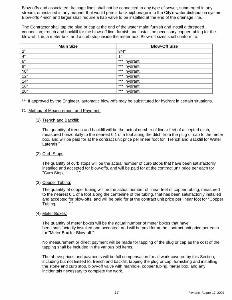
Blow-offs and associated drainage lines shall not be connected to any type of sewer, submerged in any stream, or installed in any manner that would permit back siphonage into the City’s water distribution system. Blow-offs 4-inch and larger shall require a flap valve to be installed at the end of the drainage line. The Contractor shall tap the plug or cap at the end of the water main; furnish and install a threaded connection; trench and backfill for the blow-off line; furnish and install the necessary copper tubing for the blow-off line, a meter box, and a curb stop inside the meter box. Blow-off sizes shall conform to:
Main Size Blow-Off Size
2” 3/4"
4" 1"
6" *** hydrant
8" *** hydrant
10” *** hydrant
12" *** hydrant
14" *** hydrant
16" *** hydrant
20" *** hydrant
*** If approved by the Engineer, automatic blow-offs may be substituted for hydrant in certain situations. C. Method of Measurement and Payment:
(1) Trench and Backfill:
The quantity of trench and backfill will be the actual number of linear feet of accepted ditch, measured horizontally to the nearest 0.1 of a foot along the ditch from the plug or cap to the meter box, and will be paid for at the contract unit price per linear foot for "Trench and Backfill for Water Laterals.”
(2) Curb Stops: The quantity of curb stops will be the actual number of curb stops that have been satisfactorily installed and accepted for blow-offs, and will be paid for at the contract unit price per each for "Curb Stop, _____”."
(3) Copper Tubing:
The quantity of copper tubing will be the actual number of linear feet of copper tubing, measured to the nearest 0.1 of a foot along the centerline of the tubing, that has been satisfactorily installed and accepted for blow-offs, and will be paid for at the contract unit price per linear foot for "Copper Tubing, _____”."
(4) Meter Boxes: The quantity of meter boxes will be the actual number of meter boxes that have been satisfactorily installed and accepted, and will be paid for at the contract unit price per each for "Meter Box for Blow-off.”
No measurement or direct payment will be made for tapping of the plug or cap as the cost of the tapping shall be included in the various bid items.
The above prices and payments will be full compensation for all work covered by this Section, including but not limited to: trench and backfill, tapping the plug or cap, furnishing and installing the stone and curb stop, blow-off valve with manhole, copper tubing, meter box, and any incidentals necessary to complete the work.

28 Revised: August 17, 2009
Payment will be made under: Trench and Backfill for Water Laterals LF Curb Stop, _____” EA Copper Tubing, _____” LF Meter Box for Blow-off EA
211 WATER SERVICE LATERALS
A. Description:
This Section consists of furnishing and installing water service laterals in an open cut trench or in unlined bores. B. Construction Requirements: Water service laterals shall be installed in accordance with Standard Drawing # 212 and # 213 in the “Standard Drawings for City Construction” manual, and these Specifications. The trench construction and backfill operations shall be performed in accordance with Section 203 of these Specifications. Prior to installing water laterals, the water main shall be thoroughly flushed using a flow velocity sufficient to scour the pipe interior. The Contractor shall trench and backfill or bore for the water lateral; tap the water main; furnish and install a corporation stop, copper tubing, meter setter, and a meter box. The threaded portion of the corporation stop shall be wrapped with Teflon tape before the stop is installed in the water main. Each meter setter shall be flushed briefly immediately after it has been installed. Bores shall be of adequate size to accommodate the lateral without causing an excessive void around the pipe. The face of the bore shall be a distance of five feet from the edge of pavement or back of curb on both sides of the roadway unless otherwise approved by the Engineer. Taps shall only be made after the water main is under pressure. No taps on dry mains will be allowed unless specific authorization is obtained from the Engineer. Taps shall be on an angle 45 degrees to a perpendicular through the centerline of the pipe. The maximum size of direct taps in water mains are shown below: The Contractor shall be equipped to make the above size taps on water mains. Tap sizes larger than the maximum tap size allowed will require a double strap service saddle. C. Method of Measurement and Payment:
(1) Trench and Backfill:
The quantity of trench and backfill will be the actual number of linear feet of accepted ditch, measured horizontally to the nearest 0.1 of a foot along the ditch from the water main to the meter box, and will be paid for at the contract unit price per linear foot for "Trench & Backfill for Water Laterals.” When a water and sewer lateral occupy the same trench, payment for “Trench and Backfill for Sewer Laterals shall be full compensation for both the water and sewer laterals.
Main Size Maximum Tap Size
4" 3/4"
6" 1"
8" 1"
12" 1 1/4"
16” and larger 2”

29 Revised: August 17, 2009
Payment will be made under: Trench and Backfill for Water Laterals LF
(2) Bores:
The quantity of bore will be the actual number of linear feet of accepted bore, measured horizontally to the nearest 0.1 of a foot along the bore from face of bore to face of bore, and will be paid for at the contract unit price per linear foot for "Bore for Water Laterals.” Where the water lateral jointly occupies a bore with a sewer lateral, payment for the sewer lateral bore shall cover both, as no separate payment will be made for the water lateral bore.
(3) Corporation Stops: The quantity of corporation stops will be the actual number of corporation stops that have been satisfactorily installed and accepted, and will be paid for at the contract unit price per each for “Corporation Stop, _____”."
(4) Copper Tubing:
The quantity of copper tubing will be the actual number of linear feet of copper tubing, measured to the nearest 0.1 of a foot along the centerline of the tubing, which has been satisfactorily installed and accepted, and will be paid for at the contract unit price per linear foot for "Copper Tubing, _____”."
(5) Meter Setter & Box:
The quantity of meter setters with associated meter boxes will be the actual number of setters with associated boxes that have been satisfactorily installed and accepted, and will be paid for at the contract unit price per each for "Meter Setter & Box, _____”." No measurement or direct payment will be made for tapping of the water main as the cost of the tapping shall be included in the various bid items.
The above prices and payments will be full compensation for all work covered by this Section, including but not limited to: trench and backfill or bore for water lateral, tapping the water main, furnishing and installing the stone and corporation stop, copper tubing, meter setter with associated meter box, and any incidentals necessary to complete the work. Payment will be made under: Trench & Backfill for Water Laterals LF Bore for Water Laterals LF Corporation Stop, _____” EA Copper Tubing, _____” LF Meter Setter and Box, _____” EA
212 ABANDON EXISTING WATER LINES:
A. Description:
This Section consists of abandoning water lines in-place by disconnecting and plugging at the main/tee as designated on the plans, or as directed by the Engineer. B. Construction Requirements: The Contractor shall provide equipment and personnel to locate and operate existing valves in order to obtain a proper close out on the existing water main. The Contractor shall disconnect and plug each water main at the existing tee.
30 Revised: August 17, 2009
The materials for abandonment of existing waterlines shall conform to the applicable Sections of these Specifications. The Contractor shall notify, in writing on forms provided by the City, all customers that will be affected by interruption of water service a minimum of twenty-four (24) hours in advance of the interruption of service. All water service lines to be abandoned shall be disconnected from the water main and shall have their ends crimped or plugged, as approved by the Engineer. This shall include removal of the service saddle or the corporation stop and installation of a full circle stainless steel repair band and stainless steel hardware. C. Method of Measurement and Payment: The quantity of Abandon __ inch Water Main will be the actual number per each that have been abandoned and accepted, and will be paid for at the contract unit price per each for "Abandon __ inch Water Main .” Abandonment of existing pipelines, larger than 2-inch diameter, in-place, shall include plugs with reaction
blocking.
The above price and payment will be full compensation for all work covered by this Section, including but not
limited to: furnishing labor, equipment, materials, excavation, removal, disposal, backfilling, compacting,
traffic control, turning water on and off, notifying customers, disconnect and plug at the main, provide
blocking, restore the area to its previous condition, and any other incidentals items that may be needed.
Payment will be made under:
Abandon __ inch Water Main EA
213 Abandon Valve Box:
A. Description:
This Section consists of abandoning valve boxes as indicated on the construction plans and as directed by
the Engineer.
B. Construction Requirements:
The Contractor shall remove the top of the valve box, and remove all debris, dirt, asphalt, stone, etc. from the
top of the box to the top of the valve. The valve box shall be filled with 3,000 psi concrete.
C. Method of Measurement and Payment:
The quantity of abandon valve boxes will be the actual number per each that have been abandoned and
accepted, and will be paid for at the contract unit price per each for “Abandon Valve Box.”
The above price and payment will be full compensation for all work covered by this Section, including but not
limited to: furnishing labor, equipment, traffic control, abandonment of existing valves and valve boxes,
including removal and disposal of the valve boxes, cleaning out box, removing top, and furnish and install
concrete.
Payment will be made under:
Abandon Valve Box EA
214 Abandon Meter Boxes:
A. Description:
This Section consists of abandoning meter boxes as indicated on the construction plans and as directed by
the Engineer.
B. Construction Requirements:

31 Revised: August 17, 2009
The abandoned meter box shall be removed in its entirety.
C. Method of Measurement and Payment:
The quantity of abandon meter boxes will be the actual number per each that have been abandoned and
accepted, and will be paid for at the contract unit price per each for “Abandon Meter Box.”
The above price and payment will be full compensation for all work covered by this Section, including but not
limited to: furnishing labor, equipment, traffic control, removal and disposal of meter box, compaction, backfill,
and restoring area to original condition.
Payment will be made under:
Abandon Meter Box EA
215 PRESSURE TESTING AND CHLORINATION OF WATER LINES
A. Pressure Testing:
The Contractor shall furnish all labor and equipment necessary to perform the pressure tests. The pressure test shall be performed by the Contractor and observed by the Engineer. The following prerequisite conditions shall have been met before any pressure testing begins:
(1) All hydrants are properly located, operable, plumb, and at correct elevation. (2) All valves are properly located, operable, and at correct elevation, with valve boxes or manholes
centered over wrench nuts, and top of box or manhole at correct elevation. (3) The water line or lines are properly vented where entrapped air is a consideration.
(4) The pipe shall be thoroughly flushed (full diameter) to remove any solids or contaminated material that
may have become lodged in the pipe. If no hydrant is installed at the end of the main, then a blow-off valve shall be provided large enough to develop a velocity of at least 2.5 feet per second in the main.
Unless modified in the project special provisions, the test pressure shall be 200 psi as measured at the lowest elevation of the line. The duration of the test shall be two hours and the test pressure shall be maintained by use of a by-pass pumping system. Allowable leakage per 1,000 linear feet of pipe per two hours shall be as indicated below:
Pipe Size (in) Allowable Leakage (Gallons)
4 0.73
6 1.11
8 1.47
10 1.84
12 2.21
14 2.57
16 2.94
20 3.68
24 4.41
30 5.52
36 6.62
48 8.83
Note: If pressure testing of the water line fails due to one or more leaking joints, those joints shall be cut out or removed from the pipe installation and closure shall be made with suitable lengths of ductile iron pipe and mechanical joint solid sleeves. Bell joint repair clamps are not permitted. B. Chlorination:
All water lines and appurtenances added to or replaced in the City of High Point water system shall be

32 Revised: August 17, 2009
properly chlorinated before being placed in service. The Inspector shall take the chlorination samples and deliver to the Ward Water Filtration Plant laboratory for approval. Any pipe subjected to contaminating materials shall be treated as directed by the engineer. Should such treatment fail to cleanse the pipe, the Contractor shall replace the pipe at no cost to the City. The Contractor shall perform the chlorination of a completed line in the following manner:
(1) Taps will be made at the control valve located in the upstream end of the line and at all extremities of the line. These taps shall be located in such a manner as to allow high-test hypochlorite (HTH) solution to be introduced into all parts of the line. (2) A water solution containing HTH (65%) available chlorine shall be introduced into the line by regulated pumping at the control-valve tap. The solution shall contain a concentration of HTH that will produce a minimum concentration of 50 ppm and a maximum concentration of 100 ppm total chlorine immediately after the introduction into the line has been completed.
The total pounds of calcium hypochlorite required to disinfect water mains with 100 ppm of chlorine are:
Pipe Size (in) 65% HTH (lbs per 1000 ft of line)
4 0.84
6 1.88
8 3.35
10 5.70
12 7.53
14 10.26
16 13.43
20 20.92
24 30.14
30 47.00
36 67.85
48 120.60
The HTH solution shall be circulated in the line by opening the control valve and systematically manipulating hydrants and taps at the line extremities. The HTH solution must be pumped into the line at a constant rate for each discharge rate in order that a uniform concentration will be maintained in the line. Water laterals shall be sterilized by the Contractor using methods acceptable to the Engineer. The Contractor shall bear the same responsibility for water laterals as he bears for water mains and appurtenances, including any costs for corrective measures needed to comply with the bacteriological requirements. The HTH Solution shall remain in the lines for a minimum of 24 hours. If directed by the Engineer the HTH solution shall remain in the lines longer than 24 hours. At the end of this period the free residual chlorine shall be a minimum of 10 ppm or the lines shall be rechlorinated. The Contractor shall exercise extreme caution at all times in order to prevent the HTH Solution from entering the City of High Point's existing water system. (3) Residual Chlorine Disposal:
The Contractor shall be responsible for reducing the amount of residual chlorine in the water through chemical dechlorination apparatus. (4) Dechlorination of Discharge Water:
The Contractor is to dechlorinate the water by use of apparatus that injects or mixes EPA approved

33 Revised: August 17, 2009
chemicals with the water to neutralize the chlorine before it is released to the ground (Pollard LPD250 Diffuser and Dechlorination System, the H20 Neutralizer manufactured by Measurement Technologies, Inc., equivalent). Residual chlorine levels shall be reduced and maintained to a maximum of 2.0 parts per million (2.0mg/l). The Contractor shall test the discharge at 15 minute intervals to insure that acceptable levels of neutralization are maintained. Discharge shall be stopped if chlorine levels exceed 2.0 parts per million. The dechlorination procedures shall be in accordance with manufacturer’s recommendations and as approved by the Engineer. Only in cases where this method is not practical for unique reasons would the City consider allowing the water to be released into a sanitary sewer. In those cases, the inspector will need to make a request at least 48 hours in advance in order for the City to determine the acceptability of the facility. This request would be made to the City’s dispatcher who would contact the necessary supervisor for evaluation. All costs incurred with these processes are to be considered incidental to other work being paid for under the various bid items in the contract.
C. Flushing and Bacteriological Sampling:
The Contractor may proceed with flushing of the lines after the timeline established above provided the free residual chlorine analysis is satisfactory. The flushing shall continue until a check shows that the lines contain only the normal chlorine residual. The project inspector shall collect water samples for bacteriological analysis after flushing of the line is complete. The Contractor shall furnish any reasonable amount of assistance that may be required by the Engineer to secure these samples. Bacteriological test results will be available 24 hours after the water samples have been submitted to the City’s Ward Water Filtration Plant Laboratory. If test results are unsatisfactory, the Contractor shall immediately rechlorinate the lines and proceed with such measures as are necessary to secure sterile lines. All laterals shall be rechlorinated during this process. At the satisfactory completion of the bacteriological requirements, the lines shall not be placed into service until the final approval is issued by NCDENR. All valves shall be fully opened, and the Engineer shall report each valve placed into service to the Public Services Department where a permanent record will be kept of the number of valve stem turns.

34 Revised: August 17, 2009
301 GENERAL DESCRIPTION This Section consists of those work common to sanitary sewer line construction. Construction operations that are unique to a particular sanitary sewer line will be covered in the contract "Special Provisions.” Operations that are common in the construction of both water and sanitary sewer lines are located in Division 4 of these Specifications. All work described herein is to be performed in accordance with the requirements in the drawings, Specifications, and the Contract documentation. 302 MATERIALS
A. Vitrified Clay Pipe for Gravity Sewer: Vitrified clay pipe shall be Extra Strength, designed and manufactured in accordance with ASTM C700. Pipe joints shall meet the requirements of ASTM C425.
B. Ductile Iron Pipe for Gravity Sewer: Ductile iron pipe for gravity sewer shall be designed for a minimum working pressure of 250 psi, and shall be manufactured in 18-foot or 20-foot lengths in accordance with ANSI A21.51. Pipe joints shall be push-on type as per ANSI A21.51, Section 51-2-6. The interior of the pipe shall be coated to a minimum dry thickness of 24 mils with an approved coal-tar epoxy having an epoxy resin content of thirty-five percent (35%) by weight in the dry film and a minimum solids content of seventy-four percent (74%) by volume. The exterior of the pipe coating shall be a minimum of 1 mil bituminous paint in according to ANSI/AWWA 151/A21.51 Section 51-8-1. All ductile iron sewer mains shall be class 51 unless otherwise approved by the Engineer. C. Pipe for Sewer Force Mains: (1) Polyvinyl Chloride (PVC) Force Main (4” to 16”):
Sanitary sewer force main pipe between four (4) inches and sixteen (16) inches in diameter shall be PVC pipe conforming to the requirements of AWWA C900 for 4-inch through 12-inch and AWWA C905 for 14-inch through 16-inch. All joints shall be integral elastomeric bell and spigot joints conforming to ASTM D3212. Gaskets shall conform to ASTM F477. PVC pipe diameter shall conform to the O.D. of ductile iron pipe. The type of PVC material, nominal pipe size, standard dimension ratio, and pressure rating shall not be less than pressure class 150. The standard dimension ratio shall not exceed 18. Markings on the pipe shall include the following: Nominal pipe size, type of plastic pipe material, SDR number, AWWA Designation with which the pipe complies, manufacturer’s name, and the pressure rating. (2) Ductile Iron (greater than 16” in diameter): Sanitary sewer force main pipe greater than sixteen (16) inches in diameter shall be ductile iron pipe designed in accordance with ANSI A21.50 for a working pressure of 350 psi. Pipe shall be manufactured in accordance with ANSI A21.51 in 18-foot or 20-foot lengths. Pipe joints shall be push-on type as per ANSI A21.51, Section 51-2-6. The interior of the pipe shall be coated to a minimum dry thickness of 24 mils with an approved coal-tar epoxy having an epoxy resin content of thirty-five
DIVISION 3: CONSTRUCTION OF SANITARY SEWER LINES

35 Revised: August 17, 2009
percent (35%) by weight in the dry film and a minimum solids content of seventy-four percent(74%) by volume. The exterior of the pipe coating shall be a minimum of 1 mil bituminous paint in according to ANSI/AWWA 151/A21.51 Section 51-8-1. All ductile iron sewer mains shall be class 51 unless otherwise approved by the Engineer.
D. SDR-26 PVC Sewer Pipe for Gravity Sewer: PVC sewer pipe shall conform to material requirements of ASTM D-3034, ASTM F-679, and ASTM D-1784. SDR-26 sewer mains shall meet all dimensional, chemical and physical requirements as outlined in ASTM D-3034 or F-679.
Pipe sizes eight inches (8”) through twenty-seven inches (27”) shall be bell and spigot type conforming to ASTM D3212 and/or Uni-Bell Uni-B-1.Gaskets shall be in accordance with ASTM F477. Solid wall PVC pipe shall not be used for sewers larger than 15 inches in diameter. E. Protection of Plastic Pipe Materials: Before, during, and after installation, plastic pipe and fittings shall be protected from exposure to sunlight and any environment that would result in damage to or deterioration of the material. Pipe shall be covered with opaque plastic film. Solvents, solvent compounds, lubricants and any similar materials required to install the plastic pipe shall be stored in accordance with the manufacturer's recommendations and shall be discarded if the storage period exceeds the recommended shelf life.
F. Manholes:
Manholes shall conform to the details and designations as shown and noted on the manhole Standards contained in the “Standard Drawings for City Construction” manual. Precast concrete manholes shall be manufactured in accordance with ASTM C478 and AASHTO M199. Joint surfaces for joints between bases, risers, and cones shall be manufactured to the joint surface design and tolerance requirements on ASTM C361. The maximum slope of the vertical surface shall be 2 degrees. The maximum annular space at the base of the joint shall be 0.10-inch. The minimum height of the joint shall be 2½-inches. Joint sealing material between manhole sections shall be rubber gasketed joints or butyl rubber. Rubber gasketed joints shall conform to ASTM C443 "Joints for Circular Concrete Sewer and Culvert Pipe, Using Rubber Gaskets.” Butyl rubber sealants shall conform to Federal Specifications SS-S-210A, AASHTO M-198, Type B-Butyl Rubber with a maximum of 1% volatile matter and suitable for application at temperatures between 10 and 100 degrees F. If butyl rubber joints are used, the surface of the joint receiving the butyl rubber shall be coated with an adhesive coating to assure that a seal is established between the rubber and the concrete.
Precast base sections shall have the base slab cast monolithically with the walls. Manhole inverts may be cast monolithically with the base section or be formed and cast into an existing base section. Openings shall provide clearances for pipe projecting a minimum of 2-inches inside the manhole. The trough shall be formed and finished to provide a consistent slope from the pipe inlet to the outlet. The minimum fall across the manhole shall be 1-inch per foot. The channel cross sectional profile shall be consistent and uniform from invert to invert. The bench shall be sloped to provide draining to the invert. No depressions, high spots, voids, chips, or fractures will be permitted along the trough. Manhole steps shall be provided in bases, risers, cones, and transitions. Steps are to be 16-inches on center. Secure steps to the wall with a compression fit in tapered holes or cast in place. Steps shall not be vibrated or driven into freshly cast concrete or grouted in place. Step pullout strength shall be a minimum of 2000 lb. when tested according to ASTM C478 (No. PS-1-PM, as manufactured by M. A. Industries, Inc., equivalent). Flexible watertight connector shall be used at pipe entrances to existing and new precast manhole structures. Flexible watertight connector shall conform to ASTM C923 and Standard Drawing # 306 in the “Standard Drawings for City Construction” manual. Flexible watertight connector’s shall be manufactured by Press Seal Gasket Corp (PSX and Cast a Seal 603/802), NPC Inc. (KOR-N-SEAL), or approved equivalent.

36 Revised: August 17, 2009
G. Combination Air Release Valves for Sewer Force Mains:
Air relief valves used in sewer force mains shall be designed to allow air to escape the pipeline when it is being filled, and when air accumulates during operation. Valves shall be made of iron with a screwed inlet connection, and have a 150 psi working pressure (APCO, equivalent). H. Tracer Wire: All underground non-metallic force main pipe shall be installed with a continuous uncoated number 10 gage copper wire tracer wire strapped to the top of the pipe with nylon cable straps at ten (10) foot spacing. The wire shall terminate above ground every 300 feet at every access point, manhole, and air release valve. The wire shall be of sufficient length to allow the wire to be uncoiled and extended one (1) foot above the finished grade. The tracer wire installation will be considered complete and acceptable for service when the Owner can trace the wire using the locating equipment. During installation, electrical conductivity shall be maintained between valves. If a wire is cut or otherwise requires splicing, the ends of the wire shall be bare, twisted together, and connected with an electrical twist cap. I. Main Line Valves for Sewer Force Mains: Valves 12-Inches and smaller shall be resilient wedge gate valves conforming to the applicable requirements of AWWA C509 Standards, with a working pressure of 250 psi, O-ring sealing, 2" square operating nut, open left and mechanical joint ends. Valves manufactured of ductile iron shall meet all applicable requirements of AWWA C515 with a working pressure of 250 psi. All interior and exterior ferrous metal surfaces shall be coated with a minimum of 8 mils of fusion-bonded coating meeting the requirements of AWWA C550. Valves may be used in sizes 4" thru 12" (Mueller, American Flow Control, M&H, Clow, Kennedy, U.S. Pipe, equivalent). Valves 24 inches and larger shall be butterfly valves, designed for underground or buried service applications. Butterfly valves shall conform fully with AWWA Standard C504 for class 150B, with a working pressure of 150 psi, unless specified otherwise in the special provisions, or on the plans. The valves shall have a 2” square operating nut - open left, horizontal shafts manufactured of stainless steel and the body manufactured of cast iron with mechanical joint ends (Mueller, Pratt, M&H, equivalent). Valve operator/actuator shall be for buried service and of the traveling nut or link and lever design with AWWA stops capable of absorbing 450 foot-pounds of input torque. Valves shall have resilient seating and the seat ring shall be manufactured of stainless steel. All internal parts shall be factory coated with a minimum of 8 mils of liquid or fusion bonded epoxy, AWWA approved for potable water. External iron surfaces shall be coated with a minimum of two coats of black asphaltic paint.
J. Concrete and Masonry: (1) Concrete:
Concrete shall conform to the requirements of Section 1000 of the NCDOT’s Standard Specifications for Roads and Structures, Latest Edition.
The classes of concrete for the different types of poured in place concrete work shall be as follows:
Type of Work Class of Concrete
Driveways, concrete encasements, blocking, manhole foundations A
Flat Work, Curb & Gutter, Trench concrete B
Class of Concrete Minimum Compressive Strength at 28 days, psi Maximum Slump, in.
A 3000 3.5
B 2500 2.5
37 Revised: August 17, 2009
(2) Masonry:
All masonry materials shall conform to the requirements of Section 1040 of the NCDOT’s Standard Specifications for Roads and Structures, Latest Edition.
K. Stone Aggregate: All stone aggregate shall conform to the requirements of Section 1005 of the NCDOT’s Standard Specifications for Roads and Structures, Latest Edition. Aggregate gradation shall conform to Table 1005-1 of the Standard Specifications.
L. Bituminous Concrete Plant Mixes:
All bituminous concrete plant mixes shall conform to the requirements of the applicable Sections of Division 6 of the NCDOT’s Standard Specifications for Roads and Structures, Latest Edition. M. Iron Castings:
Manhole rings and covers, valve boxes, grates, and other miscellaneous castings shall conform to the applicable details and dimensions shown in the “Standard Drawings for City Construction” manual and these Specifications.
N. Transition Couplings:
All transition couplings are to be Mueller, Maxi Fit, Fernco-Strong Back, Mission, Romac, Gladding-McBean Repair Couplings or pre-approved equal unless otherwise specified by the City of High Point.
303 SANITARY SEWER LINE CONSTRUCTION
A. Description:
This Section consists of furnishing and installing sewer pipe in an open cut trench. B. Construction Requirements:
The Contractor will be required to install ductile iron pipe, vitrified clay pipe, or SDR-26 PVC Pipe as designated on the drawings. Pipe installation shall conform to all applicable ASTM provisions for the installation of ductile iron pipe, vitrified clay pipe, and SDR-26 pipe, and these Specifications. Protect pipe during handling against impact shocks and free fall. Do not permit lifting hooks to come in contact with premolded joint surfaces. Handle pipe having premolded joint rings or attached couplings so that no weight, including the weight of the pipe itself, will bear on or be supported by the jointing material. Care shall be taken to avoid dragging the spigot ring on the ground or allowing it to be damaged by contact with crushed stone or other hard objects. All pipes shall be examined carefully for soundness and specification compliance immediately before installation. Defective pipe or pipe that does not comply with the Specifications shall be marked and held for inspection by the Engineer, who may prescribe corrective repairs or reject the pipe. Clean joint contact surfaces immediately prior to jointing. The Contractor shall use lubricants, primers, adhesives, and methods recommended by the pipe or joint manufacturer. Using offset reference stakes set by the approved layout, the Contractor shall lay all pipe straight between changes in alignment and at uniform grade between changes in grade unless directed otherwise by the Engineer. When jointed in the trench, the pipe shall form a true and smooth line. Keep trenches dry during pipe laying. Unless directed otherwise by the Engineer, start pipe laying at the lowest point and install the pipe so that the

38 Revised: August 17, 2009
spigot ends point in the direction of flow. C. Method of Measurement and Payment:
The quantity of sewer pipe will be measured horizontally, to the nearest 0.1 of a foot, along the centerline of the pipe from centerline of manhole to centerline of manhole, and will be paid for at the contract unit price per linear foot for "(Type of pipe) Sanitary Sewer Pipe, ____” that has been satisfactorily installed and accepted. The above price and payment will be full compensation for all work covered by this Section including but not limited to: furnishing, hauling, and installing all pipe, making all joint connections, and performing all leakage tests.
Payment will be made under:
(Type of pipe) Sanitary Sewer Pipe, ____” LF
304 TRENCH AND BACKFILL A. Description:
This Section consists of excavating, backfilling, compacting, and cleaning up a trench for sewer lines installation. B. Construction Requirements:
The trench shall be excavated to the centerline alignment shown in the drawings. The alignment will be referenced in the field by offset stakes set by the Contractor. The depth of the trench shall conform to the profile shown in the drawings. The depth will also be referenced in the field by the same offset stakes.
Trench width at the top of the pipe shall not exceed the nominal diameter of the pipe plus three feet without approval of the Engineer. Trench walls shall not be undercut. If the Contractor chooses to excavate past the maximum trench width, the Contractor will be responsible for all costs beyond the maximum trench width.
Trench sheeting, shoring, or bracing shall be used where shown in the drawings, specified in the Special Provisions, or as directed by the Engineer to: protect the utility under construction, allow construction to be performed according to drawings and specifications, or to prevent damage to property. The Contractor shall adhere to all OSHA requirements concerning trench sheeting, shoring, or bracing during all trench excavation. Where trench sheeting, shoring, or bracing is used, the trench width may be increased accordingly. Trench protection shall be left in place at least until the pipe has been laid and backfilled to a point two feet above the pipe. The removal of sheeting shall be done in such a manner as to minimize the loss of friction between the backfill and trench walls. Where directed by the Engineer the sheeting shall be cut off and left in place. Sheeting shall not be braced against the pipe or in any manner that will allow concentrated loads or horizontal thrusts to be transmitted to the pipe. Whenever a movable steel box is used in place of sheeting, care shall be taken to protect the integrity of the pipe bedding and to prevent the pipe from moving when the steel box is moved. The pipe must be secured to prevent longitudinal movement. Excavated material shall be placed in a manner that will not obstruct the work, endanger the work or otherwise cause a threat to the welfare of the public. Trench excavation shall be carried out in such a manner as to conform to the line and grade shown in the drawings; excavation shall proceed in advance of pipe laying only as far as the Engineer will permit. The trench shall be braced and drained in order that workers may work inside the trench safely and efficiently. Discharge from pumps shall be led to natural drainage channels, to drains, or to storm sewers. Erosion control shall be maintained when discharging water into natural drainage channels.
39 Revised: August 17, 2009
Trench width may vary with the depth of trench and nature of the excavated material, but in any case shall be of sufficient width to permit the pipe to be laid and jointed properly and the backfill to be placed and compacted properly. For payment purposes, the trench maximum trench width will be 3 feet plus the nominal diameter of the pipe without approval of the Engineer. Pipe foundation shall at all times be such that the pipe rests uniformly on the trench bottom. Bell holes shall be dug. No pipe will be accepted where the bells of the pipe are supporting the weight of the pipe. Should the trench pass over water or other previous excavation, the trench bottom shall be sufficiently compacted to provide support equal to that of the native soil. Care shall be taken to prevent damage to the existing installation. Any part of the trench excavated below grade shall be corrected with approved, compacted material before the pipe is laid. Where the subgrade is unstable or water is present in quantities sufficient to make uniform bedding of the pipe impossible, the Contractor shall stabilize the trench bottom with stabilization stone, as directed by the Engineer, and as described in Section 305, Trench Stabilization and Pipe Bedding. There are a number of different trench conditions that may be encountered on a project. The Proposal provides for crushed stone for trench stabilization and pipe bedding as shown on the plans or detailed in the special provisions. Provision is also made in the Proposal for replacement backfill material. Wherever, in the opinion of the Engineer, the existing soil is suitable for bedding purposes, it shall be used; where the existing soil is not suitable, the Engineer may direct that crushed stone or select material be used for bedding. Trench conditions will be the basis for deciding how to properly bed the pipe. Backfill material to a point one (1) foot above the pipe shall be select material. If this material is not available on the site, the Engineer may direct that replacement backfill material be brought in or that crushed stone be used for backfill. Trench conditions will be the basis for deciding how to backfill the pipe to the one-foot point. The following provisions shall apply for the bedding and backfilling of ductile iron pipe, SDR-26 PVC Pipe, or vitrified clay pipe. Backfill material to a point one (1) foot above the barrel of the pipe shall be selected materials free of large stones or clods larger than 1 ½ inches in diameter and shall be placed and compacted as follows:
(1) Subgrade to Springline of Pipe:
Material shall be hand placed and hand tamped under the lower haunches of the pipe and then brought to the springline of the pipe with either hand or power tamps. Care shall be taken to avoid damage to the pipe in the tamping operation.
(2) Springline to One Foot Above Pipe:
Care shall be exercised in tamping directly above the pipe to prevent damage to the pipe.
(3) One Foot Above Pipe to the Surface of the Ground:
Backfill material shall be placed and compacted or consolidated to produce a uniformly dense backfill load on the pipe and to minimize voids in the material. Rocks and boulders shall be excluded from backfill and no stone larger than 4 inches in diameter shall be used in the backfill. The Contractor shall furnish Class III or better "Embedment Material", at no additional cost to the City, at trench locations where Class IV materials are encountered. The Contractor shall also dispose of excess Class IV materials at no additional cost to the City. At trench locations where Class V materials are encountered the Contractor shall furnish Class III or better "Embedment Material" as directed by the Engineer. The Contractor will receive compensation for furnishing Class III or better "Embedment Material" at trench locations where Class V materials are encountered under the items of crushed stone for trench stabilization and pipe bedding or replacement backfill material as provided for in the Proposal. The final 8” lift in lawns shall be free of stones greater than one and a half (1.5) inches.

40 Revised: August 17, 2009
Deficiency of backfill material shall be supplied by the Contractor where this deficiency results from any cause other than rejection of unsuitable backfill material (other than rock) by the Engineer. In cases where the Engineer directs, the Contractor shall dispose of unsuitable backfill material and provide suitable backfill material. The conditions under which the Engineer will authorize payment for select backfill material are set forth in Section 407, Select Backfill Material. All trenches shall be completely backfilled at the end of each day's work, unless directed otherwise by the Engineer. No backfilling of frozen material will be allowed.
C. Method of Measurement and Payment:
The quantity of “Trench & Backfill ____’ Cut for ____” Sewer Lines” will be the actual number of linear feet of trench and backfill computed from the existing centerline profile to the pipe invert for the various cut depths, or as directed by the Engineer. The above price and payment will be full compensation for all work covered by this Section, including but not limited to: excavating a trench for sewer pipe and manholes, appurtenance sheeting, shoring or bracing the trench, preparing the trench bottom, backfilling and compacting the trench, disposing of excess excavation, and restoring the area to its previous condition. Payment will be made under:
Trench & Backfill ____’ Cut for ____” Sewer Lines LF
305 TRENCH STABILIZATION AND PIPE BEDDING
A. Description:
This Section consists of undercutting unstable trench bottoms and replacing the undercut material with clean # 57 stone. Also covered by this Section is the furnishing and placing clean # 57 stone for pipe bedding. Pipe bedding, laying conditions, and maximum depth of cover for ductile iron pipe shall conform to Standard Drawing # 233, SDR-26 PVC pipe shall conform to Standard Drawing # 322, and vitrified clay pipe shall conform to Standard Drawing # 323 in the “Standard Drawings for City Construction” manual. B. Construction Requirements:
Where the subgrade is found to be unstable or it includes ashes, cinders, refuse, organic material, or other unsuitable material, such material shall be removed to depth ordered by the Engineer, and replaced with an approved stabilization stone. The depth of crushed stone used for foundation and bedding shall depend upon the severity of the condition of the trench bottom soil or material. The amount of crushed stone to be used by the Contractor shall, in all cases, be designated by the Engineer. Carefully prepare bedding so that the pipe after installation will be true to line and grade. The placement and compaction of bedding stone beneath the pipe should be done in such a manner that provides a uniform and continuous support beneath the pipe at all points between bell holes or pipe joints. After each pipe has been brought to grade, aligned, and placed in final position, deposit and densify sufficient bedding material under the pipe haunches and on each side of the pipe to hold the pipe in proper position during subsequent pipe jointing, bedding, and backfilling operations. Bedding material shall be placed uniformly and simultaneously on each side of the pipe to prevent lateral displacement. C. Method of Measurement and Payment:
The stone will be measured by being weighed in trucks on approved platform scales or by other approved weighing devices. No deduction will be made for any moisture contained in the stone at the time of weighing. The Contractor shall exercise care in transporting, stockpiling, and placing the stabilization or bedding

41 Revised: August 17, 2009
stone. Stone that is wasted by the Contractor through improper procedures or negligence shall be deducted from payment quantities. The quantity of trench stabilization and pipe bedding stone will be paid for at the contract unit price per ton for “# 57 Stone for Trench Stabilization" and “# 57 Stone for Pipe Bedding" for the actual number of tons of stone which has been incorporated into the completed and accepted work. No measurement or direct payment will be made for undercutting trench bottoms, as the cost of undercutting shall be included in the price per ton bid for trench stabilization stone. The above prices and payments will be full compensation for all work covered by this Section, including but not limited to: undercutting trench bottoms, furnishing, hauling, any stockpiling, placing, and the tamping of crushed stone used for trench stabilization or pipe bedding.
Payment will be made under: # 57 Stone for Trench Stabilization TN # 57 Stone for Pipe Bedding TN
306 MANHOLE CONSTRUCTION
A. Description: This Section consists of furnishing and installing precast concrete manhole.
B. Construction Requirements:
All standard sewer manhole sections shall conform to Standard Drawing # 300, # 301, # 310, # 311, # 312, # 313, # 314, or # 315 in the “Standard Drawings for City Construction” manual depending on the size of sewer pipe to be installed, manhole type, and manhole location. All utility manhole ring and covers for roadway applications as shall conform to Standard Drawing # 307 in the “Standard Drawings for City Construction” manual, and shall have no more than two, four inch (4”) precast concrete grade rings. Manhole ring and covers shall be made of gray cast iron and shall conform to AASHTO M105 and ASTM A48, Class 35B (U.S. Foundry, Ring: USF 669, Cover: Type-KY, East Jordan Iron Works, Ring: V-1384-1, Cover: V-1384, or approved equivalent). All sanitary sewer outfalls manholes shall conform to Standard Drawing # 308 or # 309 in the “Standard Drawings for City Construction” manual. Outfall Manhole lockable ring and covers shall be made of gray cast iron and shall conform to AASHTO M105 and ASTM A48, Class 35B (Standard Drawing # 308: U.S. Foundry, Model 8020600 or East Jordan Iron Works, Model V1484-3 Frame with V1384GS Camlock Cover; Standard Drawing # 309: U.S. Foundry, Model 725, East Jordan Iron Works Model 2026ZVH Frame with 2027A1GS Camlock Cover, or approved equivalent). Manholes constructed as part of an Outfall shall have the cast iron ring and cover assembly anchored directly to the cone section. A bitumastic strip shall be provided between the frame and manhole cone section to reduce infiltration. The Contractor installing the manhole ring and cover and/or his representative shall be responsible for ensuring that these dimensional requirements are met. If the ring and cover do not conform to these dimensions, the Contractor will assume all liability and will remove and replace the ring and cover at no additional cost to the City. Manhole inverts shall conform to Standard Drawing # 304. Manholes with precast inverts may be used. Boots shall be required for all sewer services and mains entering the manhole. Where designated on the drawings, or directed by the Engineer, a manhole with an inside drop connection shall be constructed. The
42 Revised: August 17, 2009
drop connections shall be constructed in accordance with Standard Drawing # 313 in the “Standard Drawings for City Construction” manual. C. Method of Measurement:
(1) Manholes:
The quantity of manholes will be the actual number of manholes that are six feet or less in depth which have been furnished, satisfactorily installed, and accepted, and will be paid for at the contract unit price each for "Manhole, CHP Standard # ___".
The above price and payment will be full compensation for all work covered by the applicable provision of this Section including but not limited to: excavation, backfilling, compaction, furnishing and placing Clean # 57 stone, furnishing and installing precast concrete manhole with steps and ring and cover, furnishing and installing all flexible connectors, necessary hardware for pipe connections, constructing inverts, performing leakage tests, providing and installing vent pipe with screens in accordance with Standard # 310, and any incidentals necessary to complete the work. (Rock excavation and select backfill material will be paid for separately under the appropriate bid item.)
(2) Manholes with Drop Connections: The Director of Public Services must authorize the use of outside drop connections. The quantity of with manholes with drop connections will be the actual number of drop connections that have been furnished, satisfactorily installed, and accepted. The quantity of manholes with drop connections and constructing drop connections into existing Manholes will be paid for at the contract price each for "Manhole, CHP Standard # 300, with Drop Connection, Standard # ___". The above price and payment will be full compensation for all work covered by the applicable provisions of this Section including but not limited to: excavation, backfilling, and compaction, furnishing and placing # 57 stone, furnishing and installing precast concrete manhole with steps and ring and cover, furnishing and installing all flexible connectors, with any necessary hardware for pipe connection, constructing drop connection and inverts, performing leakage tests, and any incidentals necessary to complete the work. (Rock excavation and select backfill material will be paid for separately under the appropriate bid item.)
(3) Extra Depth for Manholes: The quantity of extra depth for manholes will be measured, to the nearest 0.1 of a foot, from the low point of the invert to the top of the casting ring. The quantity of extra depth for manholes will be the actual number of vertical feet of manhole over six feet in depth, that has been furnished, satisfactorily installed, and accepted and will be paid for at the contract unit price per linear foot for "Extra Depth for CHP Standard # ____ Manhole.” The above price and payment will be full compensation for all work necessary to furnish and install additional vertical depth over six feet in dimension for precast concrete manholes. Payment will be made under: Manhole, CHP Standard # ___ EA Manhole, CHP Standard # ___, with Drop Connection, Standard # ____ EA Extra Depth for CHP Standard # ____ Manhole LF

43 Revised: August 17, 2009
307 MANHOLE ADJUSTMENT RINGS:
Where denoted in the plans or as directed by the Engineer, the Contractor shall furnish and install manhole
adjustment rings. The manhole adjustment rings shall conform to Standard Drawing # 501.01 in the “Standard
Drawings for City Construction” manual.
Payment for furnishing and installing the manhole adjustment rings will be made at the contract unit price per each for “Manhole Adjustment Ring.” Such price and payment will be considered full compensation for all work to furnish and install the extension inserts and any incidentals necessary to complete the work.
308 INSTALLATION OF SEWER PIPE INTO EXISTING MASONRY MANHOLES The Contractor will be required to install sewer pipe into existing manholes at the locations shown or designated on the drawings. All proposed sewer lines that flow into the existing manhole shall have been installed, tested, and accepted prior to cutting into the existing manhole and installing the connecting section of sewer pipe. Unless designated otherwise in the Special Provisions, no direct payment will be made for installing sewer pipe into existing manholes as such work will be considered incidental to other work being paid for under the various bid items in the contract. The work will include but not be limited to: controlling the flowing sewage, excavation, cutting into the existing manhole, constructing inverts, grouting around the new pipe, constructing pipe plugs, backfilling, cleanup, and any incidentals necessary to complete the installation in a satisfactory manner. 309 CORING EXISTING PRECAST MANHOLES All proposed sanitary sewer mains and laterals that will tie into a precast concrete manhole shall be cored at the elevations shown in the drawings or as designated by the Engineer. The openings through the existing manhole walls shall be cored with a suitable coring machine. An approved watertight flexible coupling shall be used to make the connection between the pipe and manhole. No direct payment will be made for coring and for furnishing and installing watertight flexible couplings, as such work will be considered incidental to other work being paid for by the various items in the contract. 310 BUILD INVERT IN EXISTING MANHOLE
A. Description:
This Section consists of constructing new inverts in existing sanitary manholes at the location shown on the
construction plans and as directed by the Engineer.
B. Construction Requirements:
The existing invert shall be removed and the new invert shall be constructed in accordance with Standard
Drawing # 304 in the “Standard Drawings for City Construction” manual.
C. Method of Measurement and Payment:
The quantity of building inverts in existing manholes will be the actual number per each that have been
constructed and accepted, and will be paid for at the contract price per each for “Build invert in existing
manhole.”
The above price and payments will be full compensation for all work covered by this Section, including, but
not necessarily limited to: removing existing invert, plugging existing lines, providing materials and labor,
constructing the invert and any other work necessary to complete building inverts.
Payment will be made under:
Build Invert in Existing Manhole EA
44 Revised: August 17, 2009
311 CONVERT EXISTING MANHOLE TO DROP MANHOLE
A. Description:
This Section consists of converting existing manholes to drop manholes at the locations shown in the drawings or designated by the Engineer. B. Construction Requirements:
The drop connection shall be constructed in accordance with Standard Drawing # 313 or # 314 in the “Standard Drawings for City Construction” manual and the following provisions: The proposed openings through existing masonry manhole walls shall be made in a neat and workmanlike manner. Flexible couplings will not be required. Grout around the proposed pipes where they enter the masonry manhole using a suitable grout mixture approved by the Engineer. The proposed openings through existing precast concrete manhole walls shall be cored with a suitable coring machine. An approved watertight flexible coupling shall be used to make the connection between the pipe and manhole. C. Method of Measurement and Payment:
The quantity of convert existing manhole into drop manhole will be the actual number per each that have been constructed and accepted, and will be paid at the contract unit price per each for "Drop Connection into Existing Manhole, Standard # ___." The above price and payment will be full compensation to construct a drop connection into an existing manhole including but not limited to: excavation, backfilling, and compaction, cutting or coring openings through the existing manhole walls, furnishing and installing the watertight flexible couplings or grouting around the proposed pipes entering the manhole, constructing the drop connection and inverts as shown on Standard Drawing # 313, and any incidentals necessary to complete the work.
Payment will be made under:
Drop Connection into Existing Manhole, CHP Standard # ___ EA
312 SEWER LATERALS & APPURTENANCES
A. Description:
This Section consists of furnishing and installing new sewer laterals and appurtenances in an open cut trench or in unlined bores at locations shown on the plans and/or as directed by the Engineer. The materials for sewer laterals and appurtenances shall conform to Standard Drawing # 330 or Standard Drawing # 331 in the "Standard Drawings for City Construction manual and these Specifications. B. Construction Requirements:
The Contractor shall trench and backfill or bore for the sewer lateral, make the lateral connection to the sewer main, furnish and install the sewer lateral with plug, one-way clean-out, combination wyes & eighth bend with plug, and vertical pipe stack. The trench and backfill operations shall be performed in accordance with all applicable provisions of Section 304 of these Specifications. Bores shall be of adequate size to accommodate the lateral without causing an excessive void around the pipe. The face of the bore cut shall be a distance of five feet from the edge of pavement or back of curb on either side of the roadway unless otherwise approved by the Engineer.
45 Revised: August 17, 2009
C. Method of Measurement and Payment: (1) Trench and Backfill:
The quantity of trench and backfill will be the actual number of linear feet of accepted ditch, measured horizontally to the nearest 0.1 of a foot along the centerline of the pipe from the sewer main to the end of the sewer lateral, and will be paid for at the contract unit price per linear foot for "Trench & Backfill ___’ Cut for Sewer Laterals."
(2) Bores:
The quantity of bore will be the actual number of linear feet of accepted bore, measured horizontally to the nearest 0.1 of a foot along the bore from face of bore to face of bore, and will be paid for at the contract unit price per linear foot for "Bore for Sewer Laterals.”
(3) Sewer Laterals: The quantity of sewer laterals will be the actual number of linear feet of pipe, measured to the nearest 0.1 of a foot along the centerline of the pipe, which has been satisfactorily installed and accepted, and will be paid for at the contract unit price per linear foot for "Sewer Laterals, ___” (Material Type).” The above prices and payments will be full compensation for all work covered by this Section, including but not limited to: trench and backfill or bore for the sewer lateral, make the lateral connection to the sewer main, furnish and install materials for making the connection including but not limited to: lateral pipe, one-way clean-out, combination wyes & eighth bend with plug, long sweep combination, vertical pipe stack, and any incidentals necessary to complete the work. Payment will be made under: Trench & Backfill ___’ Cut for Sewer Laterals LF Bore for Sewer Laterals LF Sewer Laterals, ___” (Material Type) LF
313 SANITARY SEWER SERVICE (NEW & REHAB)
A. Connection to DIP & VCP Sanitary Mains:
All service laterals shall be service weight cast-iron soil pipe conforming to ASTM A74. Epoxy lined ductile iron sewer pipe, pressure class 350, may be required that have less than three feet of cover. Examples of compliant combination wyes and eighth bends, on which equivalence will be compared: (Charlotte Pipe Model SV-33, or approved equivalent).
B. Connection to SDR-26 Sewer Mains:
Schedule 40 PVC/DWV 1120 pipe, conforming to ASTM D1785, with a pressure rating of 220 psi shall be used on all PVC SDR-26 sanitary sewer mains. Schedule 40 PVC pipe and fittings shall meet the requirements of ASTM’s D1784, D2665, and D1785. Examples of compliant combination wyes and eight bends, on which equivalence will be compared: (Genova 72540- 4” one piece, Charlotte 501- 4” one piece, Charlotte 503- 6” two pieces, or approved equivalent). C. Sewer Air Relief Valve Corporation Stop on Force Mains: Sewer air relief valve corporation stops shall be equivalent to corporation stops used in water relief valve applications; see 208-F for Air Relief Valve Corporation Stops.

46 Revised: August 17, 2009
314 SEWER FORCE MAINS
A. Description:
This Section consists of furnishing and installing ductile iron pipe for sewer force mains in an open cut trench at the locations shown on the drawings, and performing the necessary pressure tests.
B. Construction Requirements:
The sewer force main installation shall conform to all applicable provisions of these Specifications and any Special Provisions. Concrete reaction blocking shall be placed at bends, tees, etc. in accordance with all applicable provisions of these Specifications. The Contractor shall furnish all labor and equipment necessary to perform the pressure tests. The pressure test shall be performed by the Contractor and shall be observed by the Engineer. The test pressure shall be 150 psi as measured at the lowest elevation of the line and the test pressure shall be maintained for two hours by use of a by-pass pumping system. Leakage allowed shall be as outlined in the Water & Sewer Section. C. Method of Measurement and Payment:
Measurement and payment for sewer force main pay items shall conform to the water line Section of these Specifications, and any applicable contract special provisions.
315 ABANDON EXISTING SANITARY SEWER LINES
A. Description:
This Section consists of abandoning designated sanitary sewer by disconnecting and plugging at the main as designated on the plans or as directed by the Engineer.
B. Construction Requirements:
The Contractor shall provide equipment and personnel to locate and abandon abandoning designated sanitary sewer by disconnecting and plugging at the main. The materials for abandonment of existing sanitary sewer lines shall conform to the applicable Sections of these Specifications. The Contractor shall notify, in writing on forms provided by the City, all customers that will be affected by interruption of sewer service a minimum of twenty-four (24) hours in advance of the interruption of service. All sewer service lines to be abandoned shall be disconnected from the main and shall have their ends plugged, as approved by the Engineer. This shall include removal of the service saddle and installation of a full circle stainless steel repair band and stainless steel hardware. C. Method of Measurement and Payment: The quantity of abandoning existing sanitary sewer main will be the actual number per each that have been
abandoned and accepted, and will be paid for at the contract unit price per each for “Abandoned __ ” Sanitary
Sewer.”
Such prices and payments will be full compensation for all work covered by this Section including, but not
necessarily limited to: excavation, removal, disposal, backfilling, compaction, and any other incidentals items
that may be needed.

47 Revised: August 17, 2009
Payment will be made under:
Abandoned __ ” Sanitary Sewer EA
316 ABANDONING EXISTING SANITARY SEWER MANHOLE
A. Description:
This Section consists of abandoning existing sanitary and storm sewer manholes as indicated on the plans or
as directed by the Engineer.
B. Construction Requirements:
All manholes to be abandoned shall have all connecting utility pipes plugged, and the top of each manhole
shall be removed to an elevation of three feet (3’) below the subgrade,
The Contractor shall backfill the area with clean #57 stone up to 4” or 8” below subgrade, and the remaining
portion shall be filled with 4” of concrete in non-roadway areas or 8” of concrete in roadways. The area shall be
compacted to a minimum 90% of the maximum dry density as determined by the AASHTO T99 Standard
Proctor-NCDOT modified.
The connecting utility pipes that do not require filling with cement grout shall be plugged in a manner
acceptable to the Engineer before the remaining manhole is filled with select earth material.
C. Method of Measurement and Payment:
The quantity of abandoning existing manholes will be the actual number of manholes per each that have been
abandoned and accepted, and will be paid for at the contract unit price per each.
Such price and payments will be full compensation for all work covered by this Section including, but not
necessarily limited to: furnishing labor, equipment, traffic control, excavating, plugging existing pipes,
backfilling, and returning area to its original condition.
Payment will be made under:
Abandoning Existing Manhole EA
317 PIPE PLUG
A. Description:
This Section consists of installing a permanent pipe plug for existing sanitary mains and manholes that will be
abandoned at various locations as shown on the plans and as directed by the Engineer.
B. Construction Requirements:
At the locations shown in the drawings or designated by the Engineer, the Contractor shall construct brick
masonry or concrete pipe plugs conforming to NCDOT Standard Drawing # 840.71.
Plug shall be installed only after the Contractor has verified that the existing sewer mains have been
abandoned and that all services have been tied over to the new system.
The Contractor shall plug the pipe by using bricks and mortar and sealing the end of the pipe with concrete.
C. Method of Measurement and Payment:
The quantity of plugs will be the actual number per each, for various sizes, which have been installed and
accepted, and will be paid for at the contract unit price per each for “Pipe Plug, NCDOT Standard # 840.71.
The above price and payments will be full compensation for all work covered by this Section including, but not
necessarily limited to: furnishing materials, installing permanent plugs, filling in abandoned invert, verifying
that all services have been tied over, and any other work necessary to complete the work.
48 Revised: August 17, 2009
Payment will be made under:
Pipe Plug, NCDOT Standard # 840.71 EA 318 ABANDON SEWER LATERAL
A. Description:
This Section consists of abandoning sewer service laterals at locations shown on the plans and as directed
by the Engineer.
B. Construction Requirements:
The abandonment of laterals shall include the removal, disposal, or salvage of castings, vertical pipe, and plugging the sewer lateral where indicated on the Drawings or as directed by the Engineer. Laterals to be abandoned on an active sewer main shall be disconnected and mechanically plugged inside the right of way and as directed by Engineer. C. Method of Measurement and Payment:
The measurement for abandoning laterals will be measured, to the nearest 0.1 of a foot along the centerline of the lateral pipe; regardless of pipe diameter or depth, and will be paid for at the contract unit price per linear foot for “Abandon Sewer Lateral.” Abandonment of cleanouts shall be considered incidental to the lateral and shall include all costs associated with plugging and restoration. The above price and payments will be full compensation for all work covered by this Section including, but not necessarily limited to: the excavation and removal of lateral and clean out, furnishing and installing an approved plug, backfill and compacting, restoring area to the original condition, and any other work necessary to complete the work. Payment will be made under: Abandon Sewer Lateral LF
319 VISUAL INSPECTION AND TESTING OF SEWER LINES
A. General:
The Contractor shall furnish all labor and equipment necessary to perform the leakage tests. The leakage test shall be performed by the Contractor and observed by the Engineer. Segments of the line shall be tested after they are completed, backfilled and compacted. The City will furnish all labor and equipment necessary to perform visual inspection of the pipeline and appurtenances. The Contractor shall furnish any reasonable amount of assistance that may be required by the Engineer to perform the visual inspections. Visual inspection of the pipeline and appurtenances shall be performed during all phases of the work and after they are completed, backfilled and compacted. The cost of additional testing due to pipe failures will be the Contractor’s responsibility. All defects in the pipeline and appurtenances shall be corrected by the Contractor at no additional costs to the City. B. Inspection for Defects:
The pipeline shall be visually inspected from each manhole by use of artificial light, reflecting sunlight, closed circuit television cameras, or other devices for visual inspection. All pipelines shall exhibit a fully circular pattern when viewed from one manhole to the following manhole. If the interior of the pipeline shows poor alignment, displaced or damaged pipe, or any other defect, the defects as designated by the Engineer shall be corrected by the Contractor at no additional cost to the City.

49 Revised: August 17, 2009
C. Test for Leakage:
All segments of the sewer line including services shall be tested for leakage. The standard method of testing pipelines for leakage shall be low-pressure air and deflection tests. The Contractor shall correct all visible leaks in pipes, manholes, and appurtenances. The City of High Point leakage test methods for sewer pipelines are as follows: (1) Low-Pressure Air Test:
The Contractor shall air test each section of the sewer main including services. The main and service lines shall be tested in accordance with ASTM C-828 or as directed by the Engineer. (2) Deflection Test: Deflection tests shall be performed on 100% of the PVC pipe installed. Maximum allowable deflection shall be 5% at any point and the Contractor shall perform the deflection test after a minimum of forty-five (45) days following installation. Deflection shall be measured by the Contractor with a "Go/No Go" gauge that is hand pulled through the pipe by means of a strong cord or cable furnished by the Contractor. Any section of pipe not meeting the 5% maximum deflection requirement shall be excavated, backfilled, recompacted, and tested until the pipe section meets the 5% deflection requirement and the City will charge the Contractor for additional testing. The Contractor shall conduct a deflection test on each section of the sewer main. The deflection test shall be performed per Uni-Bell Uni-B-6.
320 VACUUM TESTING OF MANHOLES All sanitary sewer manholes constructed by the Contractor shall be vacuum tested for leakage in the presence of a City Inspector. The vacuum test will not apply to any existing manholes that have been converted to drop manholes by the Contractor. The Contractor shall furnish all labor, equipment, and any appurtenant items necessary to satisfactorily perform the vacuum test. All testing equipment shall be approved for vacuum testing manholes. Each manhole shall be tested after assembly and prior to backfilling unless directed otherwise by the Engineer. All lifting holes and pipes entering the manhole shall be plugged with an approved non-shrink grout. The Contractor shall securely brace the plugs in order to keep them from being drawn into the manhole. The test head shall be placed at the inside of the top of the cone section of the manhole and the seal inflated in accordance with the manufacturer's recommendations. No one shall be inside the manhole during testing. A vacuum of 10-inches of mercury shall be drawn and the vacuum pump shut off. With the valves closed, the elapsed time for the vacuum to drop to 9-inches of mercury shall not be less than the times shown in the table below:
(Times shown are minimum elapsed times for a drop in vacuum of 1-inch of mercury). If the manhole fails the initial test, necessary repairs shall be made to the exterior of the manhole with an approved non-shrink grout while the vacuum is still being drawn. Re-testing shall proceed and continue until a satisfactory test is accomplished. No visible leaks shall be observed from inside the manhole. All temporary plugs and braces shall be removed upon completion of vacuum test.
Diameter of Manhole (in.)
Manhole Depth, X, (ft) 48 60 72
X ≤ 10 Time (S)
60 75 90
10 ≤ X ≤15 75 90 105
X ≥ 15 90 105 120

50 Revised: August 17, 2009
There will be no direct payment for the work covered by this Section as the cost will be incidental to other pay items in the contract. 321 VIDEO INSPECTION OF SEWER LINES: The Contractor will be responsible to perform a video inspection of the sewer line once it is completed and cleaned. Television inspection information will be provided to the City of High Point Public Services Department for all public mains and connecting services. The City of High Point will review the approved recorded information and contact the appropriate parties to confirm the results. The inspector will be provided a report with each section identified and linked to DVD disc with all inspection footage included for each section. Quality of video inspection will be to industry acceptable standards clearly showing any potential defects. There will be no direct payment made for T.V. inspection as the cost will be incidental to other pay items in the contract. Prior to being approved to perform any independent video inspection, the firm should show examples of their work, quality of video, and provide a print out of screen data (a previous project would be good). This should be submitted to City of High Point, Engineering Services Department, located at 211 S. Hamilton Street.
Approved “As-Built” plans will be required for TV inspection.
Sewer under pavement is not considered complete until any required pavement is in place and the manhole rims are adjusted to grade with the sewer line cleaned out.
All video shall be recorded on “DVD.”
Video taping of mains shall be done after any cleaning or jetting operation is complete and immediately after water has been introduced into the main.
Every foot of pipe shall be recorded with zero beginning at first manhole and ending with next manhole.
Laterals shall be recorded from the top of cleanout to the main. A minimum of five gallons of water shall be poured into the stack immediately before the lateral is recorded.
The camera should have the capabilities to viewing the pipe at 360 degrees with on screen print out of data.
A report form for every segment of line shall be submitted, this should include the firm submitting the report, date, project name, upstream and downstream invert elevations, manhole depths, length between manholes, pipe diameter and material type.
Any video inspection report that doesn’t clearly show the line and connecting service laterals and/or not meeting the above requirements will be rejected.
In the event that repairs are required, the repaired segment of line will need to be inspected by means of the video inspection process for final approval.
322 FORCE MAIN TESTING: After each section of line is completed, the Contractor shall subject that section to a hydrostatic test. Each section to be tested shall be slowly filled with water and air shall be carefully expelled from the line. A pressure equal to the rated working pressure of the pipe, not less than 150 psi shall be applied to the line at the test pump and shall be maintained for a minimum period of three consecutive hours. During the test, all pipe, fittings, valves, and joints shall be examined for defects. Leaking joints shall be watertight. No pipe installation will be accepted until the leakage evaluated at the working pressure of the pipe for three hours is less than the number of gallons per hour as determined by the formula on the next page:

51 Revised: August 17, 2009
A= Allowable gallons of leakage per hour L= Length of pipe being tested S= Nominal diameter of pipe in inches
No additional compensation will be made to the Contractor for repair of defects, and the removal or replacement of backfill material.
A= 10 gallons X (S) (L) 5,280 feet X 24 hours
52 Revised: August 17, 2009
401 GENERAL DESCRIPTION This Section consists of those work common to water and sanitary sewer line construction. Construction operations that are unique to a particular water or sanitary sewer line will be covered in the contract "Special Provisions.” All work described herein is to be performed in accordance with the requirements in the drawings, Specificatoins, and the Contract documentation. 402 MOBILIZATION
A. Description:
The work covered by this Section consists of work and operations necessary to mobilize personnel and equipment to the project site, establishment of all offices, buildings, and other facilities necessary to begin work on the project, and for all other fixed costs that may be reasonably charged to the initiation of a new project.
B. Basis of Payment:
The quantity of Mobilization will be paid for as contract lump sum price. Partial payments for mobilization will be made with the first and second partial pay estimates, and will be made at the rate of 50% of the lump sum price on each pay estimate provided the amount bid for mobilization does not exceed 5 percent of the total amount bid for the contract. Where the amount bid for the item of mobilization exceeds 5 percent of the total amount bid for the contract 2½ percent of the total amount bid will be paid on each of the first two partial pay estimates, and that portion exceeding 5 percent will be paid on the last partial pay estimate. The above price and payment will be full compensation for all work covered by this Section, including but not limited to: movement of personnel, equipment, supplies, and incidentals to the project site, establishment of offices, buildings, and other facilities necessary for work on the project, the removal and disbandment of those personnel, equipment, supplies, incidentals, or other facilities that were established for the prosecution of work on the project, and for all other work and operations that shall be performed for costs incurred prior to beginning work on the various items on the project site. Payment will be made under:
Mobilization LS
403 SUBSURFACE EXPLORATION
A. Description:
This Section consists of furnishing equipment and personnel to investigate actual subsurface conditions for utility lines and other underground systems to obtain information to complete the work. B. Construction Requirements:
The Contractor shall provide all necessary equipment and personnel to perform subsurface exploration at locations within the project as directed by the Engineer. C. Method of Measurement and Payment:
The quantity of subsurface exploration will be the number of hours, measured to the nearest 0.5 of an hour, that has been completed, and will be paid at the contract unit price per hour for "Subsurface Exploration.”
DIVISION 4: WORK COMMON TO WATER AND SEWER LINE CONSTRUCTION
53 Revised: August 17, 2009
The Contactor should not construe subsurface exploration as payment for work that would normally be a part of construction.
If the Engineer determines that a larger excavation is required to perform subsurface exploration under the asphalt pavement, the removal and replacement of roadway pavement shall be paid for separately under the bid items "Remove & Replace Roadway Pavement” and "Incidental ABC Stone Base,” respectively. The above price and payment will be full compensation for all work covered by this Section, including but not limited to: furnishing equipment, personnel, excavation, backfilling, pavement patch, traffic control, and any incidentals necessary to complete the work. Payment will be made under:
Subsurface Exploration HR
404 TRAFFIC CONTROL A. Description:
This Section consists of furnishing materials, erecting, maintaining, and removal of traffic control devices on the project. B. Construction Requirements:
The Contractor shall furnish, install, maintain, relocate, and remove traffic control devices in accordance with the MUTCD, NCDOT Construction and Maintenance Operation Supplement to the MUTCD, construction plans, specifications, and directed by the Engineer. All temporary traffic control devices furnished by the Contractor shall remain the property of the Contractor unless otherwise specified in the contract. The Contractor shall provide, erect, maintain, and remove “NO PARKING” signs no less than twenty-four (24) hours in advance along both sides of any road where parking would inhibit the Contractor’s operation. The “NO PARKING” signs shall be installed on portable barricades and shall be placed no more than 100 linear feet apart.
C. Method of Measurement and Payment:
There will be no measurement made for any temporary traffic control device used under this contract. The quantity of traffic control will be at a lump sum price as follows: An amount equal to twenty percent (20%) of the lump sum price for Traffic Control will be paid on the first partial payment estimate. Subsequent payments shall be equal to twenty percent (20%) of the lump sum price plus the percentage that the project is completed until the sum of all payments equals the contract lump sum price.
The quantity of traffic control will be paid for at the contract unit price per lump sum for "Traffic Control.” The above price and payment will be full compensation for all work covered by this Section, including but not limited to: furnishing materials, erecting, maintaining, replacing, and removal of traffic control devices. Payment will be made under:
Traffic Control LS
405 CONSTRUCTION STAKES, LINES & GRADE
A. Description: This Section requires the Contractor to provide all construction layouts, surveying, stakeout, and engineering
54 Revised: August 17, 2009
necessary for the proper control of construction operations in accordance with this provision, unless otherwise approved by the Engineer.
A. B. Construction Method: The City will furnish horizontal centerline control and establish elevation benchmarks. The location for these
control points and benchmarks will be shown in the plans. The Engineer will reference the centerline control points and the references furnished to the Contractor. The Contractor shall verify the validity of the references and benchmark elevations prior to beginning the construction layout. Any discrepancies noted shall be brought to the attention of the Engineer. Utilizing the benchmarks and horizontal control points established by the City, the Contractor shall lay out the work and shall be responsible for all measurements that may be required for the execution of the construction in conformity with the plans and specifications or authorized revisions thereto.
When Virtual Reference Station (VRS) methods are used to establish stakes, the system shall be localized to
the control provided by the City. The Contractor shall be responsible for the preservation of City furnished centerline control, references, and
benchmarks. The Contractor shall establish and identify clearing limits. The Contractor shall provide all additional stakes including but not limited, to centerline, Y-line, connections, ramps, loops, slope stakes, right-of-way markers, fine grade stakes, construction benchmarks, and other reference marks or points that may be necessary to provide alignments and grades for construction of all roadways, structures, and miscellaneous items.
The Contractor shall perform any staking or restaking as deemed necessary by the Engineer to ensure all
roadways, structures, and miscellaneous items are constructed in accordance with the established lines and grades. It shall be the responsibility of the Contractor to advise the Engineer of horizontal or vertical alignment revisions needed to establish smooth transitions to existing facilities. When requested by the Engineer, the Contractor shall check the accuracy of the stakeout and keep cost records to verify the cost of checking the stakeout. When the original stakeout is found to be correct, the City shall reimburse the Contractor, if requested, for the verified actual cost of checking the stakeout. Payment for such additional surveying will be limited to an amount that does not exceed that which would have been made had the additional surveying been performed under the provisions of the City of High Point force account work. The final determination of the amount to be paid will be that of the Engineer and his decision will be final. Where the original stakeout is found to be in error, the cost of checking and correcting the stakeout shall be at no cost to the City of High Point.
In addition, the Contractor shall stake these alignments as determined by the Engineer for estimating
quantities for payment. The Contractor shall set stakes to establish lines grades for subgrade, base, curb, and related items at intervals along the line of work not greater than fifty feet (50’). When the Engineer determines that horizontal or vertical alignments require the spacing of the stakes to be closer than fifty feet (50’) feet, the stakes shall be set accordingly. Grade stakes shall be set at intervals specified herein but at offsets determined by the Contractor to facilitate checking of all subgrade, base, curb, and pavement elevations including those in crossovers, intersections, and irregular shaped areas. The Contractor shall set slope stakes at all stations and half stations in accordance with the procedures established by the City.
Fine grade or other grade stakes required for the construction of the project shall be set as the work
progresses. Fine grade hubs (blue tops) shall be set on both sides of each roadbed with distances and grades referenced to either the finished centerline or edge of pavement grade, as appropriate. Structure construction stakes and other reference control marks shall be set at sufficiently frequent intervals
to ensure that all components for the structure are constructed in accordance with the lines and grades shown in the plans. The Contractor will be responsible for all structure alignment control, grade control, and all necessary calculations to establish and set these controls.
The Contractor shall make available to the Engineer all survey records made by his forces. The Engineer
reserves the right to check, correct where necessary, or require any layout work to be revised. Survey field notes, drawings, electronic data files, and other survey records shall be available to the Engineer upon request for review during the project, and all survey as-built data shall be submitted upon completion of the work. All inaccuracies in the construction stakeout shall be corrected by the Contractor prior to the

55 Revised: August 17, 2009
Contractor being permitted to perform the affected work. Consideration will not be given for any extension of contract time or additional compensation due to delays, corrective work, or additional work that may result from construction layout, surveying, and engineering required by this provision except when such delays, corrective work, or additional work is through no fault of the Contractor.
The Contractor shall provide drainage location stakes, a sketch of the drainage system, and grades and
elevations of the drainage system to the Engineer for review and approval prior to beginning work on a drainage system. In so doing, the Contractor will be responsible for investigating all existing and proposed utilities, all proposed utility construction, and existing drainage system; locating all utilities, all proposed utility construction, all existing drainage system; and considering their locations and elevations in the stakeout of the drainage system.
For the utility work to be performed under the contract, the Contractor shall provide utility construction stakes;
a sketch of the utility construction system; grades and elevations of the utility construction system; and elevations of the existing utilities, existing drainage system; and elevations of the existing utilities, existing drainage system, and proposed drainage system to the Engineer for review and approval prior to beginning work on a utility construction system. The Contractor will be responsible for investigating all utilities, all proposed drainage systems, and all existing drainage systems and considering their locations and elevations in the stakeout of the utility construction.
When the Contractor is required to perform additional investigative surveying, which in his opinion could not
have been reasonably anticipated and is not customary or inherent to the construction industry, he shall notify the Engineer in writing prior to beginning such additional surveying. The Contractor shall keep records to verify the cost of this investigative surveying. When the Engineer determines that the additional investigative surveying could not have been reasonably anticipated, the City shall reimburse the Contractor for the verified actual cost of performing the additional investigative survey. Payment for such additional surveying will be limited to an amount that does not exceed that which would have been made had the additional surveying been performed under the provision of the City of High Point force account work. The final determination of the amount to be paid will be made by the Engineer, and his determination will be final. When the Engineer determines that the Contractor could have reasonably anticipated the need to perform the investigative survey, or such survey is customary or inherent to the construction industry, such investigative survey shall be at no cost to the City as such cost shall be considered to be a part of the work required by the City.
The Contractor shall furnish personnel, working under the supervision of a Registered Professional Engineer
or Registered Land Surveyor, who are fully qualified and capable of establishing or reestablishing all line and grade points necessary to complete the work in accordance with plan dimensions and to the tolerance generally acceptable to the degree of precision in surveying required for the work being performed. The Contractor shall not engage the services of any person(s) employed by the City of High Point for the performance of any of the work covered by this item. All surveying equipment, stakes, and any material and equipment necessary to perform the work shall be furnished by the Contractor and shall be acceptable to the Engineer.
The Contractor is responsible to secure proper lines, grades, and dimensions in the completed work, and he
shall correct all errors caused by him at no cost to the City. Before the City accepts the work, the Contractor shall submit as-built drawing information including
calculations, survey field notes, drawings, and electronic data files to the Engineer upon completion of as-built drawings.
C. Method of Measurement and Payment:
The quantity of construction staking will be at a lump sum price as follows: An amount equal to twenty percent (20%) of the lump sum price for Construction Staking will be paid on the first partial payment estimate. Subsequent payments shall be equal to twenty percent (20%) of the lump sum price plus the percentage that the project is completed until the sum of all payments equals the contract lump sum price.
The quantity of construction staking will be paid for at the contract lump sum price for “Construction
Surveying.”
56 Revised: August 17, 2009
The above price and payments will be full compensation for all work covered by this section, including but not necessarily limited to: furnishing personnel, surveying equipment, stakes, sketches, supplying as-built information including calculations, data files, stakeout records, cut sheets, and any material and equipment necessary to perform the construction surveying.
Payment will be made under: Construction Surveying LS
406 ROCK EXCAVATION
A. Description:
This Section consists of blasting, excavating, removing and disposing of rock from water and sewer trenches. Rock is defined as solid, ledge rock that’s located in a water or sewer trench, which, in the opinion of the Engineer, cannot be removed practically without the use of drilling and blasting or special techniques such as drilling and wedging. Excavated boulders or rock fragments with a volume greater than ½ cubic yard may be classified as rock by the Engineer.
B. Construction Requirements:
Prior to performing any blasting operations, the Contractor must obtain a blasting permit from the City of High Point Fire Department and appropriate Government agency. The approval of the Engineer shall be obtained before any blasting of rock takes place. The Engineer may fix the hours of blasting if he deems it necessary.
All applicable Federal, State, and Local regulations pertaining to transporting, storing, and using explosives shall be met. The Contractor shall keep explosive materials that are on the job in specially constructed boxes with locks. Failure to comply with the Specification shall be grounds for suspension of blasting operations until full compliance is made. The Contractor shall take all necessary precautions to protect life and property while engaged in blasting operations. When there is a danger of rock or overburden being thrown by a blast, an approved type of blasting mat shall be used. The Engineer will approve the blasting mat for type of construction but not for adequacy. No blasting will be allowed unless a galvanometer is used to check cap circuits. When blasting takes place within 500 feet of a utility structure or property that could be damaged by vibration, concussion, or falling rock, the Contractor is required to keep a blasting log containing the following information: 1. Date of shot 6. Depth of overburden 2. Time of shot 7. Amount and type of explosive used in each hole 3. Foreman's name 8. Type of caps used 4. Number and depth of holes 9. Weather conditions 5. Name of person conducting blasting operation The blasting log shall be kept in an orderly manner and shall be available for inspection by the Engineer. Rock shall be excavated to the same limits as earth except that the trench shall be excavated 6 inches lower than the barrel of the pipe and bottom of the manhole, and outside diameter of manhole plus three feet. The trench bottom shall be brought to the proper grade with select material and compacted to the same density specified for backfill material. Where, in the opinion of the Engineer, blasting constitutes an unacceptable danger to utilities or property, means other than blasting may be required for removal of rock.

57 Revised: August 17, 2009
Rock excavated from the trench shall be disposed of in an approved waste area. Compliance with these Specifications does in no way relieve the Contractor of legal liabilities relative to blasting operations.
C. Blasting Requirements:
Prior to blasting operations, the Contractor shall submit qualifications for their blaster or blasting
subcontractor to the Engineer/Owner for approval, and provide proof of insurance for the blasting
subcontractor.
When a seismic monitoring subcontractor or a professional subcontractor are used to perform pre-blast, post-
blast, and damage analysis, the Contractor shall supply the qualifications of the monitoring firm to the
Engineer.
The Contractor shall provide their operating procedures for submitting blasting damages, handling claims and
any other pertinent information related to the blasting damage claim process to the Engineer/Owner.
The Contractor shall submit to the Engineer/Owner for approval a blasting plan a minimum of two (2) weeks
prior to blasting in the proximity of buildings, structures, and/or utilities.
Two (2) weeks prior to performing pre-blast surveys, the Contractor shall provide written notification to all
property owners within 500 feet of the blasting zone.
The written notification shall include:
Contractor’s name
Project name
State that they are working for the City of High Point
Define the pre-blast survey
Provide a contact name and number to call to set up an appointment
Provide any additional information
Prior to notifying the property owners, the Contractor shall submit a sample letter to the Owner for approval.
Additional notifications may be required for structures close to the blast or special conditions.
Two (2) weeks prior to any blasting, the Contractor shall notify all property owners within 500 feet of the
blasting zone of the intent to perform blasting within the area. The letter shall include the Contractor’s name,
project name, state that they are working for the City of High Point, the approximate date of blasting, explain
the warnings that will be used, and provide contact information in case of damage. Damage claim forms are
available from the owner. Additional notifications maybe required for structures close to the blast or special
conditions.
Prior to blasting, the Contractor shall perform pre-blast surveys for structures near the blast. Structures shall
include but not be limited to: houses, buildings, pools, roads, sidewalks, concrete structures, and exposed
utilities. The pre-blast survey shall contain a detailed inspection of the exterior and interior of the building
showing locations of all damages to the house and surrounding structures.
The pre-blast survey shall include photographic and written documentation, and shall be done in the
presence of the property owner. If a property owner refuses to allow a pre-blast survey, the Contractor shall
thoroughly document the refusal.
Danger Blasting Zone signs shall be installed along roads, public ways, near occupied buildings adjacent to
58 Revised: August 17, 2009
the blast area, and other locations deemed necessary to warn the public of the blasting. Depending on the
ignition devices used in the blasting, additional electronic device signs may be required.
The Contractor shall notify the Engineer and owner at least 24 hours in advance of the blasting. The owner or
their representative shall witness all blasting operations.
Blasting shall be performed Monday through Friday from 9:00 AM through 3:30 PM unless otherwise
approved by the Engineer.
The Contractor shall notify emergency services immediately prior to blasting.
When blasting in close proximity of utility lines, the Contractor shall contact the utility owner prior to blasting.
It is strongly encouraged that a representative for the utility owner be present during the blasting.
The Contractor shall monitor all blasting in proximity to structures with seismographs that measure ground
vibration and air shock. The number and location of the seismographs shall be approved by the Engineer. A
minimum of one seismograph shall be used.
Blasting Announcements:
Five minutes prior to blasting, the Contractor shall sound a series of long blasts on a horn and siren for 1
minute followed by an announcement over a loud speaker “Attention, Attention, we will be blasting in five
minutes” and repeat.
One minute prior to blasting, the Contractor shall sound a series of short blasts on a horn and siren followed
by an announcement over a loud speaker “Attention, Attention, we will be blasting in one minute” and repeat.
After the one-minute time and confirmation that the area is clear, the announcement of “Fire in the Hole” will
be made over the loud speaker and the blast shall be detonated.
After the shot is complete and the area has been determined to be safe, the Contractor shall sound a
prolonged blast on the horn and siren followed by the announcement over the loud speaker “All clear.”
A post-blast survey may be required if the blast exceeds established vibration parameters, there’s a report of
damage, or as directed by the Engineer. The post blast survey shall be similar to the pre-blast survey.
Should a claim for damages be submitted, a copy of the damage claim form should be immediately sent to
the Engineer.
All blasting shall be videotaped from the 5-minute warning through the “all clear” signal. The video camera
shall be placed on a tripod, located at a safe distance from the blast, so the entire blast may be seen. The
camera shall record the date, time, sound, and record video in a digital format on a mini-DVD tape, video
CD, or video DVD.
Each tape, CD, or DVD shall be in a case. Both the case and video media shall be labeled showing the job
name, date of the video, and location. An index shall be provided showing the sequence and location of each
shot on the video. Still pictures of before/after the shot may be submitted, but will not be used in place of the
video.
Once the blasting operations are complete, the Contractor shall deliver a copy of all pre-blast surveys,
blasting log, video of the shot, and post-blast surveys to the Engineer.
59 Revised: August 17, 2009
The Contractor shall immediately notify the Engineer of any damage claims and send a copy of the damage
claim form.
D. Method of Measurement and Payment:
The quantity of rock excavation at the contract unit price per cubic yard for "Rock Excavation in Trench” will
be the number of cubic yards of rock, measured in a rectangular prism along the vertical centerline of the
trench.
The maximum width of the prism shall be equal to the nominal diameter of the pipe plus three feet. The
height of the prism shall be the average height in feet of the rock profile as measured to the nearest 0.1 foot
from a point six inches below the pipe barrel, and 6 inches lower than the manhole to the top of the rock. The
length of the prism shall be the number of linear feet of trench rock measured for payment along the vertical
centerline of the trench.
Where rock is encountered in excavating for manholes, rock will be figured for the outside diameter of the
structure plus three feet (3').
The above price and payment will be full compensation for all work covered by this Section, including but not limited to: drilling, wedging, matting and blasting, excavating the rock, disposing of excavated rock, and any incidentals necessary to satisfactorily complete the work. Payment will be made under:
Rock Excavation in Trench CY
407 SELECT BACKFILL MATERIAL
A. Description:
This Section consists of providing select backfill material to backfill trench lines, undercut, manholes, and
drainage structures.
B. Construction Requirements:
Select backfill materials shall meet the requirements of Section 1016 of the Standard Specification for Roads
and Structures for the North Carolina Department of Transportation, January 2002 edition.
When the Engineer determines that the material excavated from the trench is unsuitable to be used as backfill material, the Contractor shall provide select backfill material that is approved by the Engineer.
When the Engineer determines that the material excavated from the trench is a suitable soil type for backfill material, but contains excessive moisture the following three conditions shall prevail:
(1) The Contractor shall reduce the moisture content of the material to an acceptable level by aerating the material adjacent to the excavated trench. No direct payment will be made for aerating the excavated material as such work will be considered incidental to other work being paid for by the various items in the contract. (2) Where the area available to aerate the excavated material is limited or insufficient, and the moisture content is above optimum for the type of soil, but compaction is attainable with extra compactive effort, the Contractor shall use extra compactive effort in obtaining the required soil density. No direct payment will be made for the extra compactive effort as such work will be considered incidental to other work being paid for by the various items in the contract. (3) Where the area available to aerate the excavated material is limited or insufficient, and the moisture content is above optimum for the type of soil, and satisfactory compaction is determined by the Engineer to be unattainable, the Engineer will authorize the Contractor to provide approved backfill material.
60 Revised: August 17, 2009
Where material suitable for backfilling has acquired excessive moisture after being excavated from the trench, the Contractor will not be compensated for providing approved backfill material.
C. Method of Measurement and Payment:
The quantity of Class I Select Backfill Material at the contract unit price per cubic yard for "Select Backfill Material” will be the actual number of cubic yards of select backfill material measured in a rectangular prism along the vertical centerline of the trench. The maximum width of the prism shall be equal to the nominal diameter of the pipe plus three feet. The height of the prism shall be the average height in feet measured to the nearest 0.1 foot from the bottom of the trench to the top of the trench less any pavement replacement structure. The length of the prism shall be the number of linear feet of replacement backfill material measured for payment along the vertical centerline of the trench. The Contractor shall adhere to all OSHA requirements concerning trench sheeting, shoring, or bracing during all trench excavation. No direct payment will be made for additional cubic yards of compacted material as may be necessary due to OSHA trenching requirements, as such work will be considered incidental to other work being paid for under the various items in the contract. The above price and payment will be full compensation for all work to provide select backfill material, including but not limited to: removing from the site and disposing of the unsuitable excavated material and furnishing, hauling, placing, compacting approved backfill material, and any incidentals necessary to satisfactorily complete the work. Payment will be made under:
Select Backfill Material CY
408 REMOVE AND REPLACE PAVEMENT FOR PIPES AND STRUCTURES A. Description: This Section consists of replacing a bituminous pavement structure in areas where the Contractor removed pavement for subsurface exploration and the installation or repair of pipelines and appurtenances. B. Construction Requirements: The pavement replacement structure shall be constructed in accordance with Standard Drawing # 500 in the "Standard Drawings for City Construction" manual and these Specifications. The Contractor shall trim or saw a neat edge along the pavement to be retained using methods approved by the Engineer. All pavement replacement shall be completed within 7 calendar days of backfilling or 500 linear feet of pipe installation. The materials and construction methods used for the pavement structure replacement shall meet all requirements of the NCDOT's Standard Specifications for Roads and Structures, Latest Edition. C. Method of Measurement and Payment:
The pavement replacement quantities will be computed in square yards using the actual trench width up to a maximum width equal to the nominal diameter of the pipe plus three feet, and will be paid for at the contract unit price per square yard for “Remove & Replace Roadway Pavement" or "Remove & Replace Asphalt Driveway." If, in the opinion of the Engineer, conditions beyond the Contractor's control require additional pavement replacement, a trench width greater than the maximum width equal to the nominal diameter of the pipe plus three feet will be used to compute pavement replacement quantities.

61 Revised: August 17, 2009
The above price and payment will be full compensation for all work covered by this Section including but not limited to: removing and disposing of the existing pavement, trimming or sawing a neat edge along the pavement to be retained, furnishing, hauling, placing, and compacting the bituminous materials, prime and tack coats, and any incidentals necessary to complete the work. The ABC stone will be paid for separately under the bid item for "Incidental ABC Stone Base.” No price adjustments will be made for Asphalt Binder for Plant Mix (liquid asphalt). Payment will be made under: Remove & Replace Roadway Pavement SY Remove & Replace Asphalt Driveway SY
409 REMOVE AND REPLACE CONCRETE FLATWORK
A. Description:
This Section consists of the removal and replacement of concrete sidewalks, driveways, and miscellaneous slabs that are removed for the installation of pipelines and appurtenances. B. Construction Requirements:
The concrete flatwork replacement shall be constructed in accordance with Standard Drawing # 500.01 in the “Standard Drawings for City Construction” Manual, and applicable provisions of Section 848 of the NCDOT's Standard Specifications for Roads and Structures, Latest Edition. The Contractor will be required to furnish a neat edge along the concrete pavement retained by sawing a neat line approximately two inches deep, with a concrete saw, before breaking the adjacent concrete pavement away. Concrete forms shall be constructed to shape, line, and dimension as indicated in the drawings or directed by the Engineer. The forms shall be braced and tied together to prevent displacement during the concrete pouring and finishing operations. The Contractor shall provide a finish on the replacement concrete that matches the adjacent concrete retained. C. Method of Measurement and Payment:
The concrete flatwork replacement quantities will be computed in square yards using the actual trench width up to a maximum width equal to the nominal diameter of the pipe plus three feet, and will be paid for at the contract price per square yard for "Remove & Replace ___” Concrete Flatwork.” If, in the opinion of the Engineer conditions beyond the Contractor's control require additional flatwork replacement, a trench width greater than the nominal diameter of the pipe plus three feet will be used to compute flatwork replacement quantities. The above price and payment will be full compensation for all work covered by this Section including but not limited to: removing and disposing of the existing concrete flatwork, sawing a neat edge along concrete to be retained, constructing forms, furnishing, hauling, placing, compacting, and finishing concrete, constructing expansion and control joints, and any incidentals necessary to complete the work. Payment will be made under: Remove & Replace ___” Concrete Flatwork SY
410 REMOVE AND REPLACE CONCRETE CURB AND GUTTER
A. Description:
This Section consists of of the removal and replacement of concrete curb and gutter at the locations shown
62 Revised: August 17, 2009
on the drawings, or designated by the Engineer. B. Construction Requirements:
After the installation of the pipelines, the Contractor shall replace the removed curb and gutter with new concrete curb and gutter. The new concrete curb and gutter shall be constructed in accordance with Standard Drawing # 502 in the “Standard Drawings for City Construction” Manual and Section 846 of the NCDOT's Standard Specifications for Roads and Structures, Latest Edition.
C. Method of Measurement and Payment:
Payment for removing and disposing of existing concrete curb and gutter and constructing new concrete curb and gutter will be made at the contract price per linear foot for "Remove & Replace 2'-6" Concrete Curb and Gutter.” The above prices and payments will be full compensation for all work of removing the existing curb and gutter and constructing new curb and gutter, including but not limited to: excavation and backfilling, furnishing and placing concrete, construction joints, and the satisfactorily disposal of removed curb and gutter. Payment will be made under: Remove & Replace 2'-6" Concrete Curb and Gutter LF
411 INCIDENTAL ABC STONE BASE
A. Description:
This Section consists of furnishing and placing a graded stone material for use in driveways, pavement cuts, temporary maintenance of traffic, and at locations directed by the Engineer. B. Construction Requirements:
The ABC stone shall meet the requirements of the Section 545 in the NCDOT's Standard Specifications for Roads and Structures, Latest Edition. The graded stone material shall be uniformly spread over the area required and then shaped and dressed to the satisfaction of the Engineer. The stone material shall be maintained until final acceptance of the individual project by reshaping and by addition of stone material when directed by the Engineer. C. Method of Measurement and Payment:
The stone will be measured by being weighed in trucks on approved platform scales or by other approved weighing devices. No deduction will be made for any moisture contained in the stone at the time of weighing. The quantity of incidental stone will be paid for at the contract unit price per ton for "Incidental ABC Stone Base.” which has been used as directed by the Engineer for driveways, pavement cuts, temporary maintenance of traffic, etc. The Contractor shall exercise care in transporting and placing the incidental stone. The Contractor shall keep the waste of stone within reasonable limits as determined by the Engineer. The City reserves the right to deduct for payment stone that has been wasted by the Contractor through improper procedures or negligence. The above price and payment will be full compensation for all work covered by this Section including but not limited to: furnishing, hauling, placing, compacting, spreading, shaping and reshaping, dressing, and maintaining the incidental ABC stone base. Payment will be made under: Incidental ABC Stone Base TN
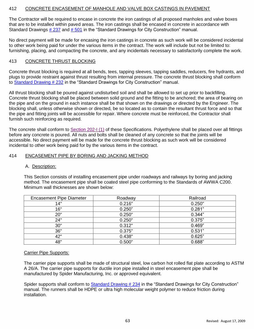
63 Revised: August 17, 2009
412 CONCRETE ENCASEMENT OF MANHOLE AND VALVE BOX CASTINGS IN PAVEMENT The Contractor will be required to encase in concrete the iron castings of all proposed manholes and valve boxes that are to be installed within paved areas. The iron castings shall be encased in concrete in accordance with Standard Drawings # 237 and # 501 in the “Standard Drawings for City Construction” manual. No direct payment will be made for encasing the iron castings in concrete as such work will be considered incidental to other work being paid for under the various items in the contract. The work will include but not be limited to: furnishing, placing, and compacting the concrete, and any incidentals necessary to satisfactorily complete the work. 413 CONCRETE THRUST BLOCKING Concrete thrust blocking is required at all bends, tees, tapping sleeves, tapping saddles, reducers, fire hydrants, and plugs to provide restraint against thrust resulting from internal pressure. The concrete thrust blocking shall conform to Standard Drawing # 232 in the “Standard Drawings for City Construction” manual. All thrust blocking shall be poured against undisturbed soil and shall be allowed to set up prior to backfilling. Concrete thrust blocking shall be placed between solid ground and the fitting to be anchored; the area of bearing on the pipe and on the ground in each instance shall be that shown on the drawings or directed by the Engineer. The blocking shall, unless otherwise shown or directed, be so located as to contain the resultant thrust force and so that the pipe and fitting joints will be accessible for repair. Where concrete must be reinforced, the Contractor shall furnish such reinforcing as required. The concrete shall conform to Section 202-I (1) of these Specifications. Polyethylene shall be placed over all fittings before any concrete is poured. All nuts and bolts shall be cleaned of any concrete so that the joints will be accessible. No direct payment will be made for the concrete thrust blocking as such work will be considered incidental to other work being paid for by the various items in the contract. 414 ENCASEMENT PIPE BY BORING AND JACKING METHOD
A. Description:
This Section consists of installing encasement pipe under roadways and railways by boring and jacking method. The encasement pipe shall be coated steel pipe conforming to the Standards of AWWA C200. Minimum wall thicknesses are shown below:
Encasement Pipe Diameter Roadway Railroad
14" 0.216" 0.250"
16" 0.250” 0.281”
20" 0.250" 0.344”
24" 0.250" 0.375”
30" 0.312" 0.469”
36" 0.375" 0.531”
42" 0.438" 0.625”
48" 0.500" 0.688”
Carrier Pipe Supports: The carrier pipe supports shall be made of structural steel, low carbon hot rolled flat plate according to ASTM A 26/A. The carrier pipe supports for ductile iron pipe installed in steel encasement pipe shall be manufactured by Spider Manufacturing, Inc. or approved equivalent. Spider supports shall conform to Standard Drawing # 234 in the “Standard Drawings for City Construction” manual. The runners shall be HDPE or ultra high molecular weight polymer to reduce friction during installation.

64 Revised: August 17, 2009
B. Construction Requirements:
The bore pit shall be no larger than that which is reasonably required to accommodate the boring and jacking operations, and shall be located at locations shown on the plans or as directed by the Engineer. When installing encasement pipe, the Contractor will be required to take all reasonable precautions to prevent damage to the roadbed above. Voids around the encasement pipe shall be kept to an absolute minimum. The Inspector shall have the authority to order boring discontinued where in his opinion damage to the roadway or railway appears likely. The Contractor shall take necessary measures to protect the roadbed before again commencing operations. Where excessive voids develop, such corrective action as is directed by the Engineer shall be taken. When the encasement pipe is to be installed through rock, the Contractor shall make the bore using the appropriate rock bit. Where encasement pipe is installed in State right-of-ways, the entire installation shall be as required by the NCDOT. Where encasement pipe is installed in Railroad right-of-ways, the entire installation shall be as required by the appropriate Railroad agency. Brick headers shall be constructed at each end of the encasement pipe in such a manner as to minimize shear on the carrier pipe. When directed by the Engineer a drain outlet shall be provided at the low end of the encasement pipe. The Contractor shall furnish and install carrier pipe supports as defined and installed per Section 414 of these Specifications, or as approved by the Engineer, on each pipe joint to keep the carrier pipe from floating or deflecting within the encasement pipe. No direct payment will be paid for these spacers as they are considered incidental to the work. C. Method of Measurement and Payment:
The quantity of encasement will be measured, to the nearest 0.1 of a foot from face of bore to face of bore for the encasement pipe that has been satisfactorily installed, and will be paid for at the contract unit price per linear foot for "Encasement by Boring and Jacking Method, ___”.” Payment will be made under: Encasement by Boring and Jacking Method, ___" LF
415 SERVICE SADDLES
A. Description:
This Section consists of installing service saddles on water and sewer lines.
(1) Water Mains:
All 1-1/2” and 2” water main taps will require a service saddle that conforms to Standard Drawing # 213 in the “Standard Drawings for City Construction” manual. Service saddles shall be made of ductile iron, and shall be a double strap design.
(2) Sewer Force Mains:
All 1-1/2” and 2” sewer force main taps will require a service saddle and air release valves. Service saddles shall be made of ductile iron, and shall be a double strap design. 3) Gravity Sewer Main: All gravity sewer taps will require a Romac Style “CB” sewer service saddle. Service saddles shall be made of ductile iron, and shall be an adjustable strap design.

65 Revised: August 17, 2009
B. Material Requirements: Ductile iron tapping saddles for water mains shall be tested and conform to all applicable standards of ANSI/AWWA C-800 and the saddle bodies shall be made of ductile iron, ASTM A395 alloy. Saddles shall be designed for a maximum working pressure of 500 psi shall be a double strap design. (Smith Blair Model 313, Mueller DR2A series, Ford F202 series, or approved equivalent). Tapping sleeve and valve installation shall conform to Section 209 of these Specifications.
C. Method of Measurement and Payment:
The quantity of service saddles will be the actual number of various sizes that have been installed and
accepted, and will be paid for at the contract unit price per each for “____ Inch x ____Inch Service Saddle.”
Payment will be made under:
____ Inch x ____Inch Service Saddle EA
416 CLEARING AND GRUBBING
A. Description:
This Section consists of cutting, removal, and satisfactory disposal of trees including the stump, undergrowth, and debris that is within the construction right-of-way. B. Construction Requirements:
The clearing and grubbing shall be performed at locations designated on the drawings and as directed by the Engineer. All brush, roots, stumps, tree laps, trees, undergrowth, and debris shall be disposed by the Contractor in approved disposal sites located away from the project. The Contractor shall conduct his operations in a manner to prevent limb, bark, or root injuries to trees, shrubs, or other types of vegetation that are to remain growing and also to prevent damage to adjacent property. The Contractor shall exercise extreme caution in order not to clear and grub areas outside of the construction right-of-way. Any areas of growth or individual trees which are to be preserved due to their desirability for landscape or erosion control purposes will be designated on the drawings or by the Engineer. The Contractor shall perform such erosion control work, temporary or permanent, as may be directed by the Engineer in order to satisfactorily minimize erosion resulting from the clearing and grubbing operations. The Contractor shall pay particular attention to environmentally sensitive areas. C. Method of Measurement and Payment:
Measurement for clearing and grubbing will be made horizontally for the actual number of acres within the construction right-of-way that have been satisfactorily cleared and grubbed, and will be paid for at the contract unit price per acre for "Clearing & Grubbing” The above price and payment will be full compensation for all work covered by this Section including but not limited to: the removal and disposal of all surface vegetation, the removal and disposal of all fences, steps, walls, footings, other foundation components, signs, junked vehicles, other rubble and debris, and the dressing up of all areas within the construction right-of-way. Payment will be made under:
Clearing & Grubbing AC
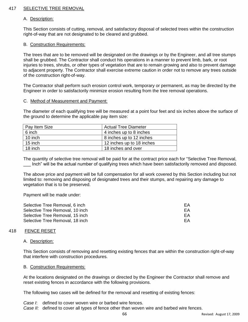
66 Revised: August 17, 2009
417 SELECTIVE TREE REMOVAL A. Description: This Section consists of cutting, removal, and satisfactory disposal of selected trees within the construction right-of-way that are not designated to be cleared and grubbed.
B. Construction Requirements: The trees that are to be removed will be designated on the drawings or by the Engineer, and all tree stumps shall be grubbed. The Contractor shall conduct his operations in a manner to prevent limb, bark, or root injuries to trees, shrubs, or other types of vegetation that are to remain growing and also to prevent damage to adjacent property. The Contractor shall exercise extreme caution in order not to remove any trees outside of the construction right-of-way. The Contractor shall perform such erosion control work, temporary or permanent, as may be directed by the Engineer in order to satisfactorily minimize erosion resulting from the tree removal operations. C. Method of Measurement and Payment:
The diameter of each qualifying tree will be measured at a point four feet and six inches above the surface of the ground to determine the applicable pay item size:
Pay Item Size Actual Tree Diameter
6 inch 4 inches up to 8 inches
10 inch 8 inches up to 12 inches
15 inch 12 inches up to 18 inches
18 inch 18 inches and over
The quantity of selective tree removal will be paid for at the contract price each for "Selective Tree Removal, ___ Inch” will be the actual number of qualifying trees which have been satisfactorily removed and disposed. The above price and payment will be full compensation for all work covered by this Section including but not limited to: removing and disposing of designated trees and their stumps, and repairing any damage to vegetation that is to be preserved. Payment will be made under: Selective Tree Removal, 6 inch EA Selective Tree Removal, 10 inch EA Selective Tree Removal, 15 inch EA Selective Tree Removal, 18 inch EA
418 FENCE RESET
A. Description:
This Section consists of removing and resetting existing fences that are within the construction right-of-way that interfere with construction procedures. B. Construction Requirements:
At the locations designated on the drawings or directed by the Engineer the Contractor shall remove and reset existing fences in accordance with the following provisions. The following two cases will be defined for the removal and resetting of existing fences:
Case I: defined to cover woven wire or barbed wire fences. Case II: defined to cover all types of fence other than woven wire and barbed wire fences.
67 Revised: August 17, 2009
The existing fence shall be removed and reset to the locations indicated on the drawings or directed by the Engineer. The fence, after resetting, shall be in a condition equal to or better than that existing before the fence was removed. The Contractor will be required to replace fence components that have been unnecessarily damaged by him. The Contractor shall maintain security of fenced areas that contain livestock during all phases of construction between the removal and resetting of the fence.
C. Method of Measurement and Payment:
The quantity for fence reset will be measured, to the nearest 0.1 of a foot along the fence from center of end post to center of end post for the length of fence that has been acceptably reset, and will be paid for at the contract unit price per linear foot for "Fence Reset, Case ___." The above price and payment will be full compensation for all work covered by this Section including but not limited to: removing, hauling, re-erecting the existing fence, and furnishing and installing any components unnecessarily damaged by the Contractor's forces. Payment will be made under: Fence Reset, Case I LF Fence Reset, Case II LF
419 REMOVE & RESET DRIVEWAY PIPE
A. Description:
This Section consists of removing and replacing existing driveway pipe that conflicts with the construction of water or sewer lines. B. Construction Requirements: The Contractor shall remove and stockpile existing driveway pipe that conflicts with the installation of the proposed pipeline or appurtenance. Immediately after the proposed pipe line or appurtenance has been installed, the Contractor shall replace the removed driveway pipe. The driveway pipe, after being replaced, shall be in a condition equal to or better than that existing before the pipe was removed. The Contractor will be required to replace, with new pipe, any of the existing driveway pipe unnecessarily damaged by him. When the Engineers determines that the existing driveway pipe is in such a poor condition that replacement would not be practicable or the pipe is of substandard material or size, the Engineer will authorize the use of new reinforced concrete pipe for replacement. The replacement pipe shall have a minimum diameter of 15 inches. The Contractor will be paid the actual invoice cost of the new pipe that was replaced. No direct payment, except actual pipe, will be made for any of the driveway pipe removal and replacement operations, as such work will be considered incidental to other work being paid for under the various bid items in the contract.
68 Revised: August 17, 2009
501 GENERAL DESCRIPTION The Contractor shall be required to take every reasonable precaution throughout the contract to prevent the erosion of soil and the sedimentation of streams, lakes, reservoirs, other water impoundments, ground surfaces, or other property as required by the Sedimentation Pollution Control Act of 1973 and the 1974 Amendments to the Act. Erosion and Sedimentation Control shall be performed in accordance with Division 16 of the NCDOT's Standard Specifications for Roads and Structures, Latest Edition, the North Carolina Erosion and Sedimentation Control Planning and Design Manual, Latest Edition, the approved plans, and the following provisions. Failure on the part of the Contractor to comply with the provisions of the approved Erosion Control Plan or to perform erosion control work as directed will result in the Engineer, Inspector, or NCDENR notifying the Contractor to comply with these provisions. If the Contractor fails to supply adequate forces and equipment to begin corrective erosion control work within 24 hours after receipt of notice, the Engineer may order all work on the job stopped and will proceed to have the work performed by others. No payment or pay item adjustments for major or minor pay items will be made to the Contractor for work performed by others. Any actual costs incurred by the City due to the failure of the Contractor to comply with these provisions will be borne by the Contractor. Such costs will include a twenty-five percent markup of the actual costs billed plus all civil penalties assessed for soil erosion and sedimentation control violations. Any costs incurred by the City for work performed by others as provided above in excess of the costs that would have been incurred had the work been performed by the Contractor will be deducted from the Contractor’s monies due. Temporary and permanent erosion control measures shall be as shown on the plans, as required by construction conditions, or as directed by the Engineer. All permanent erosion control work shall be incorporated into the work at the earliest practicable time. Temporary erosion control measures shall be coordinated with permanent erosion control measures and all other work on the project to assure economical, effective and continuous erosion control throughout the construction and post construction period and to minimize siltation of streams, lakes, reservoirs, other water impoundments, ground surface, or other property. Erosion control measures shall not be removed without NCDENR permission. The Contractor shall be responsible to develop and submit an erosion control plan to NCDENR for approval for all work outside of the construction limits including but not limited to: haul roads, equipment and material storage sites, borrow pit operations, and disposal of waste and debris. The Contractor shall restore the above areas to the satisfaction of the Engineer. The Contractor shall be responsible for all damages to public or private property arising out of his negligence in providing proper erosion control measures. No direct payment will be made for any erosion control measures outside of the construction right-of-way. 502 TIMELINE FOR SEEDING The Contractor shall provide proper ground cover to exposed areas within 15 working days following completion of any land-disturbing phase of construction. Permanent seeding and mulching or proper ground cover will be provided for all disturbed areas within 15 working days or 30 calendar days (whichever is shorter) following completion of construction activity. Deviations from this procedure shall be only with the written authorization of the Engineer. 503 TEMPORARY MULCH Temporary mulch may be used for the prevention of excessive soil erosion during construction operations where it is impossible or impractical to perform permanent seeding and mulching because of weather conditions. Stabilize any
DIVISION 5: EROSION AND SEDIMENTATION CONTROL
69 Revised: August 17, 2009
graded area where no active construction will take place for 21 days by temporary seeding and mulching. Temporary mulch may be straw, fiber mats, netting, bark, wood chips, or other suitable material acceptable to the Engineer and shall be reasonably clean and free of noxious weeds and deleterious material. Mulch shall be spread uniformly over the area by hand or by means of appropriate mechanical spreaders or blowers to obtain an application satisfactory to the Engineer. The Contractor shall apply a sufficient amount of asphalt or other type material to assure that the temporary mulch is properly held in place. 504 PERMANENT SEEDING & MULCHING Seeding and mulching shall conform to Standard Drawing # 612 in the "Standard Drawings for City Construction” manual, Division 16 of the NCDOT's Standard Specifications for Roads and Structures, Latest Edition, and the following provisions. The work includes seedbed preparation, liming, fertilizing, seeding and mulching of all disturbed areas.
A. Materials:
(1) Lime:
The lime shall be finely pelletized dolomotic agricultural limestone containing not less than ten percent
magnesium oxide.
(2) Fertilizer:
The fertilizer shall be standard commercial 10-10-10 analysis. All fertilizer shall be delivered in bags
bearing the manufacturer’s name, chemical analysis of the product, and the weight. If not used
immediately upon delivery, the fertilizer shall be stored in such a manner that will not allow it to harden
or destroy its effectiveness.
(3) Grass Seed:
Shall be an approved mixture based on regional and seasonal considerations. Purity of seed shall be
a minimum of ninety percent, and the germination shall be a minimum of eighty five percent. The seed
label shall be a “Certified Seed” label.
B. Seedbed Preparation:
If no soil test is performed, the application rate per acre shall be : 4000 pounds of limestone, 800 pounds of
superphosphate, and 1,000 pounds of 10-10-10 fertilizer. Lime, super phosphate, and fertilizer shall be
applied uniformly and mixed with the soil.
The preparation of seedbeds shall not be done when soil is frozen, extremely wet, or when the Engineer
determines it is an unfavorable working condition.
(1) Non-Lawn Areas:
All non-lawn areas shall be prepared by disking, cross-disking, harrowing, or other approved method
to produce a friable and thoroughly pulverized three inch deep seedbed. Remove weeds, rocks over
three inches in diameter, and any undesirable material which hinders future maintenance of areas
designated to be seeded.
(2) Lawn Areas:
All seeded areas subject to be mowed and maintained as lawn areas shall be prepared such that no secondary raking shall be necessary in order for a lawnmower to pass smoothly over the seeded area. All clods shall be broken up, and the upper four to six inches of soil shall be prepared into an
acceptable seedbed using a soil pulverizer or other approved method to produce a friable and
thoroughly pulverized seedbed.

70 Revised: August 17, 2009
Remove weeds, rocks over one and a half inches in diameter, and any undesirable material that
hinders lawn maintenance.
C. Seeding:
Once the seedbeds have been approved by the Engineer, the grass mixture shall be sowed at the appropriate rate that conforms to Standard Drawing # 612 in the "Standard Drawings for City Construction” manual. All seeded area shall be rolled or cultipacked to insure that the seed is worked into the soil to a depth of ½ inch. D. Mulch: Mulch shall be wheat straw, oat straw, peanut hay, or grass hay. Mulch shall be applied immediately after seeding and spread uniformly without clumps or bunches at a rate of 5,000 pounds per acre (approximately 133 bales per acre). Mulch shall be held in place by applying a sufficient amount of emulsion asphalt or approved binding material.
The rate of application for emulsion asphalt shall be 10 gallons per 1000 square feet. The Contractor shall use types RS or CRS emulsion asphalt in traffic areas.
505 PAYMENT FOR EROSION CONTROL
A. Temporary Silt Fence: Temporary Silt Fence shall conform to Standard Drawing #600 and #600.01 in the "Standard Drawings for City Construction manual. The Contractor shall not remove the silt fence until directed by NCDENR. The quantity of silt fence will be the actual number of linear feet of silt fence, measured to the nearest 0.1 of a foot, that has been satisfactorily installed at the locations shown on the drawings or asdirected by the Engineer, and will be made at the contract unit price per linear foot for “Temporary Silt Fence” and per each for “Stone Outlet for Silt Fence.” Such price and payment shall be full compensation for all labor, tools, equipment, materials, install stone outlets at low points and/or as directed by the Engineer, and incidentals necessary to furnish, install, and maintain a silt fence; remove and dispose of collected silt and surplus spoil, restore area to its original condition, and seed and mulch the resultant disturbed areas immediately behind the removal. Payment will be made under:
Temporary Silt Fence LF Stone Outlet for Silt Fence EA B. Temporary Mulch: The quantity of temporary mulch will be the number of acres, measured along the surface of the ground, over which temporary mulch has been placed as directed by the Engineer. No payment will be made for temporary mulch that has been required because of the Contractor's failure to perform work properly or to seed and mulch the work according to schedule. Payment at the contract price per acre for "Temporary Mulch" shall be full compensation for all labor, tools, equipment, and materials necessary to furnish and place temporary mulch for erosion control.
Payment will be made under: Temporary Mulch AC

71 Revised: August 17, 2009
C. Matting for Erosion Control: The description of work, placing of matting, method of measurement, and basis of payment shall conform to Section 1631 of the NCDOT's Standard Specifications for Roads and Structures, Latest Edition. Unless otherwise specified on the plans or directed by Engineer, the matting material used for erosion control shall be excelsior matting. The Contractor shall follow manufacturers recommended installation procedures and a copy of the installation instructions supplied to the engineer. Payment will be made under: Matting for Erosion Control SY D. Seeding and Mulching: The quantity of seeding and mulching will be the actual number of acres (square yards) of seeding and mulching, measured along the surface of the ground, which has been completed and accepted. Payment for "Seeding and Mulching" shall be full compensation for all work of seeding and mulching including but not limited to: furnishing and applying limestone, fertilizer, seed, mulch, asphalt, and other materials, cleanup of vegetation, stones, and other debris prior to seedbed preparation and mulching; seedbed preparation; and maintenance. Payment will be made under: Seeding and Mulching, Non-Lawn Areas AC Seeding and Mulching, Lawn Areas AC Seeding and Mulching, Non-Lawn Areas SY Seeding and Mulching, Lawn Areas SY E. Stone for Erosion Control: The description of work, material requirements, construction methods, method of measurement, and basis of payment shall conform fully to Section 1610 of the NCDOT's Standard Specifications for Roads and Structures, Latest Edition. Stone for erosion control shall be placed in locations as shown on the plans or as directed by the Engineer.
Payment will be made under:
Stone for Erosion Control, Class A TN Stone for Erosion Control, Class B TN #57 Stone for Erosion Control TN F. Plain Rip-Rap: The rip-rap material shall meet the requirements of Section 868 of the NCDOT's Standard Specifications for Roads and Structures, Latest Edition. Rip-rap used for erosion control measures will be paid for at the contract unit price per ton "Plain Rip-Rap, Class ___" and shall be full compensation for all work but is not limited to: all excavation, embankment preparation, backfilling, equipment, materials, and incidentals necessary to furnish, haul, and place rip-rap for erosion control. Payment will be made under: Plain Rip-Rap, Class I TN Plain Rip-Rap, Class II TN
72 Revised: August 17, 2009
G. Temporary Diversion Berm The construction and maintenance of the diversion berms shall conform to the details shown on the plans and as directed by the Engineer. All diversion berms will be removed after the site has been stabilized, and at the direction of NCDENR. The area shall be restored to its original grade and the resultant disturbed areas will be seeded and mulched immediately behind the grading operation. The measurement of temporary diversion berm will be the number of linear feet, measured along the surface of the ground, over which temporary mulch has been placed as directed by the Engineer, and will be paid at the contract unit price per each for “Temporary Diversion Berm.” Such price and payment shall be considered full compensation for all labor, equipment, stone, materials and incidentals necessary to construct, maintain and remove the temporary sediment basin for erosion control. Payment will be made as: Temporary Diversion Berm LF H. Temporary Sediment Trap The Contractor shall construct and maintain temporary sediment basins according to the dimensions shown on the plans or as directed by the Engineer. All temporary sediment basins will be removed after the site has been stabilized and at the direction of NCDENR. The area will be restored to its original grade and the resultant disturbed areas will be seeded and mulched immediately behind the grading operation. Payment for the work will be made at the contract unit price per each for “Temporary Sediment Trap.” Such price and payment shall be considered full compensation for all labor, equipment, fabric, stone, materials, and incidentals necessary to construct, maintain and remove the temporary sediment basin for erosion control. Payment will be made under: Temporary Sediment Trap EA I. Filter Fabric for Rip Rap: Filter fabric for rip rap used for erosion control measures will be paid for at the contract unit price per square yard for “Filter Fabric for Rip Rap” and shall be full compensation for all labor, equipment, materials and incidentals necessary to furnish, install, and remove and dispose of filter fabric for rip rap. Filter fabric for rip rap shall meet the requirements of Section 1056 of the NCDOT's Standard Specifications for Roads and Structures, Latest Edition. Payment will be made under: Filter Fabric for Rip-Rap SY J. Temporary Construction Entrance: The Contractor shall construct and maintain construction entrances at the locations shown on the plans or as designated by the Engineer. Construction entrances will be paid for at the contract unit price per each for “Temporary Construction Entrance that conforms to Standard Drawing # 605.01 for local in the "Standard Drawings for City Construction manual” or “Temporary Construction Entrance, NCDOT Std. # 1607.01” , and shall be full

73 Revised: August 17, 2009
compensation for all labor, equipment, materials and incidentals necessary to furnish, maintain, remove construction entrances, and return area to original condition. Temporary Construction Entrances will be removed after the site has been stabilized and at the direction of the Engineer. The area shall be restored to its original grade and the resultant disturbed areas will be seeded and mulched immediately behind the grading operation. The Engineer may require the removal of the stone or backfill for seeding purposes. Payment will be made under: Temporary Construction Entrance, CHP Std. # 602 for Local EA Temporary Construction Entrance, NCDOT Std. #1607.01 EA
K. Temporary Stream Crossing:
At the locations shown on the plans or as designated by the Engineer, the Contractor shall construct and maintain temporary stream crossings that conform to Standard Drawing # 605 and # 605.01 in the "Standard Drawings for City Construction manual.” Temporary stream crossing must be installed prior to allowing any access or haul activities across the creek. The Contractor will be responsible to maintain the crossing for the duration of the project until the Engineer approves the conversion to a permanent crossing. The Contractor will construct in a way as to limit siltation to the stream. If in the Engineer’s opinion the Contractor is not following installation guidelines or is performing work in a manner that may cause silting of the creek, the Engineer may halt the Contractor’s work in the area of the creek.
Payment for the work will be made at the contract unit price per each for “Temporary Stream Crossing, CHP STD. # ___.” Such price and payment shall be considered full compensation for all labor, equipment, fabric, stone, culverts, materials, and incidentals necessary to construct, maintain and remove the temporary creek crossing. Payment will be made under: Temporary Stream Crossing, CHP Std.# 605 EA
Temporary Stream Crossing, CHP Std.# 605.01 EA
L. Temporary Rock Silt Check: The temporary rock silt check dams shall be placed at locations shown on the plans and as directed by the Engineer. The Contractor shall construct and maintain temporary stream crossings that conform to NCDOT Std.# 1633.02. The Contractor will be responsible to remove the temporary stone ditch checks as the project is stabilized and as directed by NCDENR. Seeding and mulching of disturbed areas shall occur immediately upon removal of these items. All resultant disturbed areas will be seeded & mulched immediately upon removal. Payment will be made under:
Temporary Rock Silt Check Type “B”, NCDOT Std.# 1633.02 EA
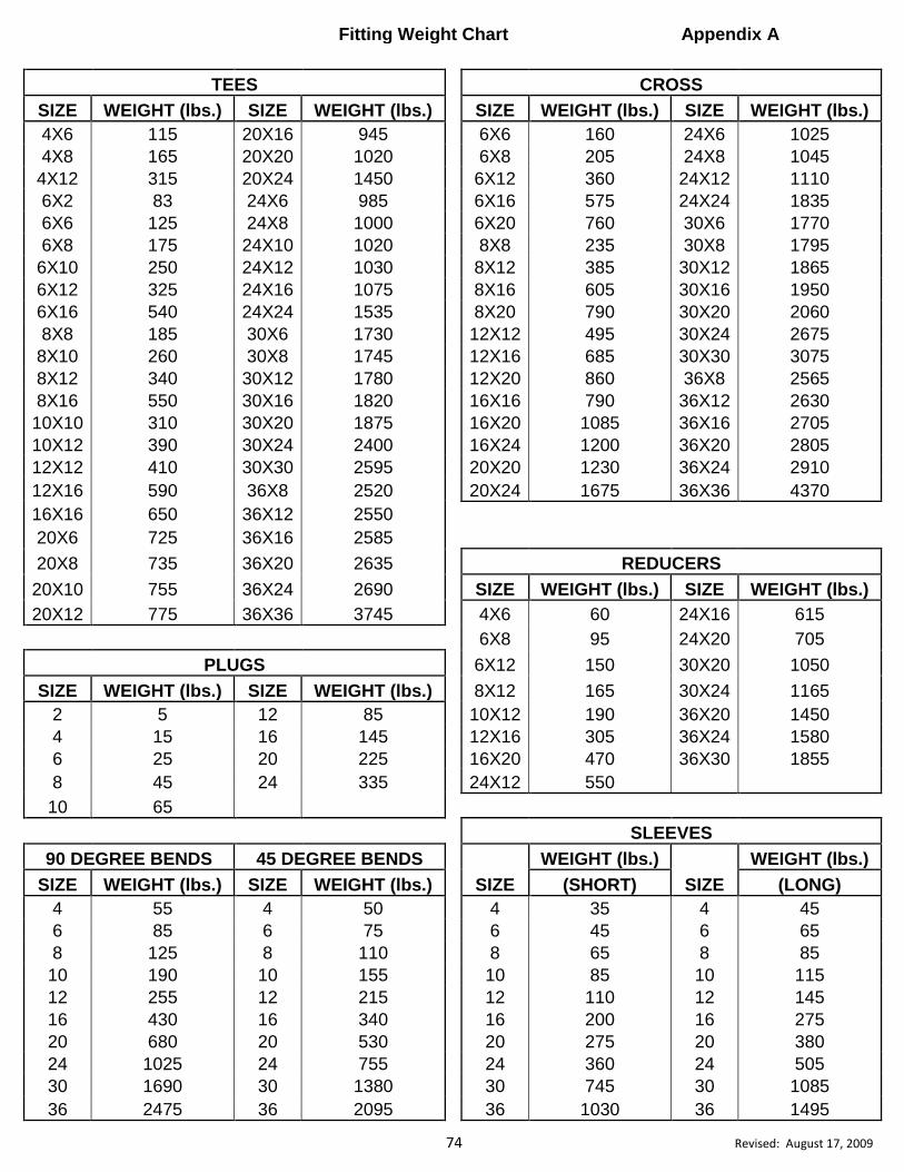
74 Revised: August 17, 2009
Fitting Weight Chart Appendix A
TEES
CROSS
SIZE WEIGHT (lbs.) SIZE WEIGHT (lbs.)
SIZE WEIGHT (lbs.) SIZE WEIGHT (lbs.)
4X6 115 20X16 945
6X6 160 24X6 1025
4X8 165 20X20 1020
6X8 205 24X8 1045
4X12 315 20X24 1450
6X12 360 24X12 1110
6X2 83 24X6 985
6X16 575 24X24 1835
6X6 125 24X8 1000
6X20 760 30X6 1770
6X8 175 24X10 1020
8X8 235 30X8 1795
6X10 250 24X12 1030
8X12 385 30X12 1865
6X12 325 24X16 1075
8X16 605 30X16 1950
6X16 540 24X24 1535
8X20 790 30X20 2060
8X8 185 30X6 1730
12X12 495 30X24 2675
8X10 260 30X8 1745
12X16 685 30X30 3075
8X12 340 30X12 1780
12X20 860 36X8 2565
8X16 550 30X16 1820
16X16 790 36X12 2630
10X10 310 30X20 1875
16X20 1085 36X16 2705
10X12 390 30X24 2400
16X24 1200 36X20 2805
12X12 410 30X30 2595
20X20 1230 36X24 2910
12X16 590 36X8 2520
20X24 1675 36X36 4370
16X16 650 36X12 2550 20X6 725 36X16 2585 20X8 735 36X20 2635
REDUCERS
20X10 755 36X24 2690
SIZE WEIGHT (lbs.) SIZE WEIGHT (lbs.)
20X12 775 36X36 3745
4X6 60 24X16 615
6X8 95 24X20 705
PLUGS
6X12 150 30X20 1050
SIZE WEIGHT (lbs.) SIZE WEIGHT (lbs.)
8X12 165 30X24 1165
2 5 12 85
10X12 190 36X20 1450
4 15 16 145
12X16 305 36X24 1580
6 25 20 225
16X20 470 36X30 1855
8 45 24 335
24X12 550
10 65
SLEEVES
90 DEGREE BENDS 45 DEGREE BENDS
WEIGHT (lbs.) WEIGHT (lbs.)
SIZE WEIGHT (lbs.) SIZE WEIGHT (lbs.)
SIZE (SHORT) SIZE (LONG)
4 55 4 50
4 35 4 45
6 85 6 75
6 45 6 65
8 125 8 110
8 65 8 85
10 190 10 155
10 85 10 115
12 255 12 215
12 110 12 145
16 430 16 340
16 200 16 275
20 680 20 530
20 275 20 380
24 1025 24 755
24 360 24 505
30 1690 30 1380
30 745 30 1085
36 2475 36 2095
36 1030 36 1495
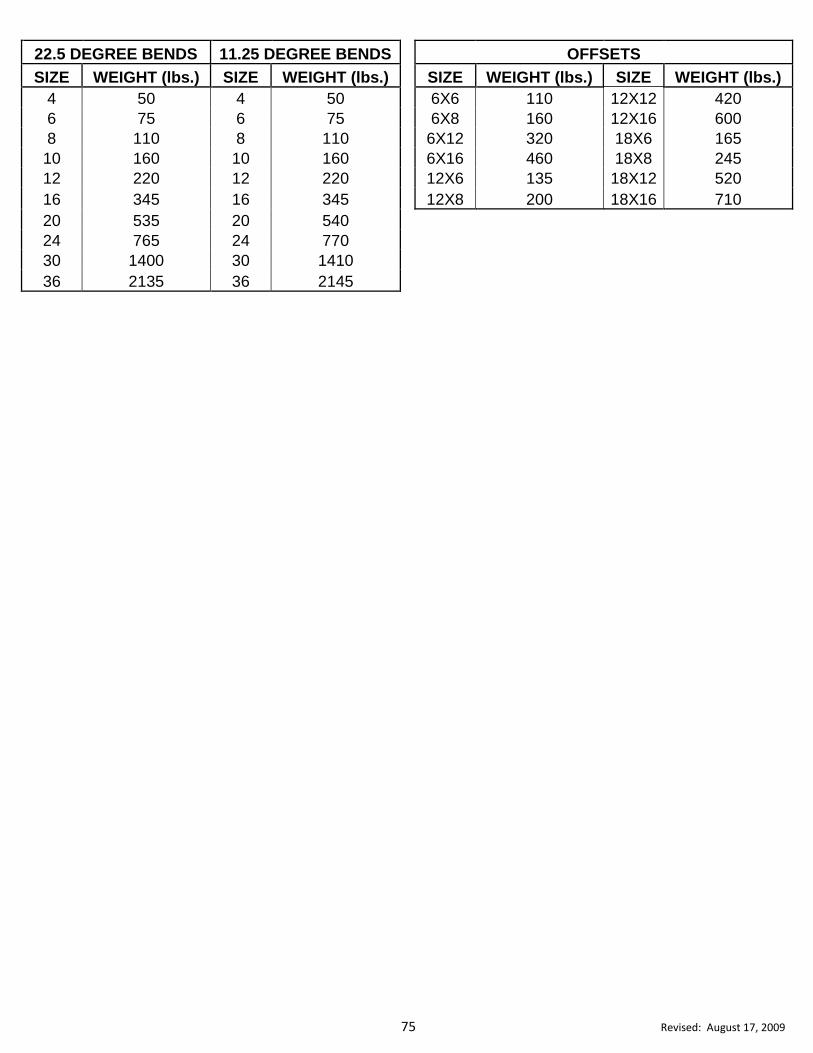
75 Revised: August 17, 2009
22.5 DEGREE BENDS 11.25 DEGREE BENDS
OFFSETS
SIZE WEIGHT (lbs.) SIZE WEIGHT (lbs.)
SIZE WEIGHT (lbs.) SIZE WEIGHT (lbs.)
4 50 4 50
6X6 110 12X12 420
6 75 6 75
6X8 160 12X16 600
8 110 8 110
6X12 320 18X6 165
10 160 10 160
6X16 460 18X8 245
12 220 12 220
12X6 135 18X12 520
16 345 16 345
12X8 200 18X16 710
20 535 20 540 24 765 24 770 30 1400 30 1410 36 2135 36 2145

76 Revised: August 17, 2009
abbreviations, 4 fertilizer, 69
air relief valves, 15,16,36 filter fabric, 72
alignment and grade, 21 final inspections, 13
bacteriological sampling, 33 fittings, 14
bedding stone, 20,40 weight chart, 74
bituminuos concrete plant mixes, 18,37 general material requirements, 4
blow-offs, 26 grass seed, 69
bore, 22,28,44 handling and storage, 21
burning restrictions, 12 hydrant, 16,25
carrier pipe supports, 63 hydrant operations, 8
check valves, 15 incidental abc stone base, 62
chlorination, 31 international home furnishings market, 12
clean-up, 12 inverts, 43
clearing and grubbing, 65 iron castings, 18,37
compaction requirements, 5 joint assembly, 22
concrete, 17,36 lime, 69
curb & gutter, remove & replace, 61 low-pressure air test, 49
driveway pipe, 67 mailboxes, 8
encasement of manhole and valve box castings in pavement, 63 maintenance of traffic, 7
flatwork, 61 major and minor contract pay items, 10
thrust blocking, 63 manholes, 35,42
construction conferences, 11 abandoning, 47
construction enterance, 72 adjustment ring, 43
contractor's representative, 10 build inverts, 43
control of material, 7 construction, 40
construction schedule, 10 convert exist manhole to drop manhole, 44
construction stakes, lines & grade, 53 coring existing precast manholes, 43
convert existing manhole to drop manhole, 44 drop connections, 42
copper pipe, 14 extra depth, 42
copper tubing, 27 inverts, 43
coring existing precast manholes, 43 installation of sewer pipe into existing manholes, 43
corporation stops, 18,29,45 ring adjustment,43
curb & gutter, remove & replace, 61 vacuum testing, 49
curb stops, 18,27 masonry, 17,36
customer service issues, 10 material, 14,34
dechlorination of discharge water, 32 matting for erosion control, 71
deflection test, 49 meter box, 17
driveway pipe, 67 abandon, 30
ductile iron pipe, 14,34 meter setters, 19
encasement pipe, 63 mobilization, 52
erosion control mulch, 69,70
payment for erosion control, 70 ncdot right of way, 8
permanent seeding & mulching, 71 night and weekend work, 12
stone for erosion control, 74 partial payment, 9
time line for ground cover, 68 pavement, remove & replace, 60
existing utilities, 8 pipe
fence reset, 66 copper, 14
DIVISION 6: INDEX

77 Revised: August 17, 2009
pipe (cont.) stone (cont.)
ductile iron, 14,34 aggregate, 17,37
PVC, 34 erosion control, class a, 71
vitrified clay, 34,47 erosion control, class b, 71
pipe plug, 49 incidental abc, 62
plastic pipe protection, 35 outlet for silt fence, 70
preconstruction conference,11 subcontractor payment, 9
pressure testing, 31 subsurface exploration, 52
quantities, 4 temporary diversion berm, 72
retainage, 9 temporary mulch, 68
residual chlorine disposal, 32 temporary rock silt check, 73
restoration of property, 7 temporary sediment trap, 75
retainer glands, 14 temporary silt fence, 70
rip-rap, 74 temporary stream crossing, 73
rock excavation, 56 thrust blocking, 64
safety and health regulations, 11 tracer wire, 36
sanitary sewer traffic control, 53
abandon, 46,48 transition couplings, 18,37
air relief valves, 36,50 trench and backfill, 19,38
construction, 37 trench stabilization, 20,40
deflection test, 49 vacuum testing, 49
force mains, 46,50 valve, 15,36
installation, 37 abandon, 30
laterals, 45,50 operation, 8
leakage test, 49 installation, 23
low-pressure air test, 49 valve box castings in pavement, 63
main line sewer valves, 36 vitrified clay pipe, 34
materials, 34 water lines
trench and backfill, 38 abandon, 29,30
trench stabilization, 40 air release valve, 15
video inspection, 50 bacteriological sampling, 33
visual inspection, 48 bore, 22
schedule of projects, 9 chlorination, 31
scope, 4 dechlorination of discharge water, 32
seed & mulch, 69,71 fittings, 14
seedbed preparation, 69 flushing, 33
seeding schedule, 69 installation, 21
seeding timeline, 68 laterals, 28
select backfill material, 59 materials, 14
selective tree removal, 66 pressure testing, 31
service line installation (new), 18 residual chlorine disposal, 32
service line installation (rehab), 18 tapping sleeve and valve with valve box, 16,25
service saddles, 64 tapping sleeve/saddle and valve, 16
silt fence, 70 trench and backfill, 19
stone trench stabilization, 20
#57 stone for erosion control, 71 valves, 15
#57 for trench stabilization, 20, 40